US6739433B1 - Tension member for an elevator - Google Patents
Tension member for an elevatorDownload PDFInfo
- Publication number
- US6739433B1 US6739433B1US09/218,990US21899098AUS6739433B1US 6739433 B1US6739433 B1US 6739433B1US 21899098 AUS21899098 AUS 21899098AUS 6739433 B1US6739433 B1US 6739433B1
- Authority
- US
- United States
- Prior art keywords
- tension member
- member according
- wires
- cords
- sheave
- Prior art date
- Legal status (The legal status is an assumption and is not a legal conclusion. Google has not performed a legal analysis and makes no representation as to the accuracy of the status listed.)
- Expired - Lifetime, expires
Links
Images


Classifications
- B—PERFORMING OPERATIONS; TRANSPORTING
- B66—HOISTING; LIFTING; HAULING
- B66B—ELEVATORS; ESCALATORS OR MOVING WALKWAYS
- B66B7/00—Other common features of elevators
- B66B7/06—Arrangements of ropes or cables
- B66B7/062—Belts
- D—TEXTILES; PAPER
- D07—ROPES; CABLES OTHER THAN ELECTRIC
- D07B—ROPES OR CABLES IN GENERAL
- D07B1/00—Constructional features of ropes or cables
- D07B1/16—Ropes or cables with an enveloping sheathing or inlays of rubber or plastics
- B—PERFORMING OPERATIONS; TRANSPORTING
- B66—HOISTING; LIFTING; HAULING
- B66B—ELEVATORS; ESCALATORS OR MOVING WALKWAYS
- B66B11/00—Main component parts of lifts in, or associated with, buildings or other structures
- B66B11/0035—Arrangement of driving gear, e.g. location or support
- B66B11/004—Arrangement of driving gear, e.g. location or support in the machine room
- B—PERFORMING OPERATIONS; TRANSPORTING
- B66—HOISTING; LIFTING; HAULING
- B66B—ELEVATORS; ESCALATORS OR MOVING WALKWAYS
- B66B11/00—Main component parts of lifts in, or associated with, buildings or other structures
- B66B11/04—Driving gear ; Details thereof, e.g. seals
- B66B11/08—Driving gear ; Details thereof, e.g. seals with hoisting rope or cable operated by frictional engagement with a winding drum or sheave
- B—PERFORMING OPERATIONS; TRANSPORTING
- B66—HOISTING; LIFTING; HAULING
- B66B—ELEVATORS; ESCALATORS OR MOVING WALKWAYS
- B66B15/00—Main component parts of mining-hoist winding devices
- B66B15/02—Rope or cable carriers
- B66B15/04—Friction sheaves; "Koepe" pulleys
- B—PERFORMING OPERATIONS; TRANSPORTING
- B66—HOISTING; LIFTING; HAULING
- B66B—ELEVATORS; ESCALATORS OR MOVING WALKWAYS
- B66B7/00—Other common features of elevators
- B66B7/06—Arrangements of ropes or cables
- B—PERFORMING OPERATIONS; TRANSPORTING
- B66—HOISTING; LIFTING; HAULING
- B66B—ELEVATORS; ESCALATORS OR MOVING WALKWAYS
- B66B9/00—Kinds or types of lifts in, or associated with, buildings or other structures
- D—TEXTILES; PAPER
- D07—ROPES; CABLES OTHER THAN ELECTRIC
- D07B—ROPES OR CABLES IN GENERAL
- D07B1/00—Constructional features of ropes or cables
- D07B1/06—Ropes or cables built-up from metal wires, e.g. of section wires around a hemp core
- D07B1/0673—Ropes or cables built-up from metal wires, e.g. of section wires around a hemp core having a rope configuration
- D—TEXTILES; PAPER
- D07—ROPES; CABLES OTHER THAN ELECTRIC
- D07B—ROPES OR CABLES IN GENERAL
- D07B1/00—Constructional features of ropes or cables
- D07B1/22—Flat or flat-sided ropes; Sets of ropes consisting of a series of parallel ropes
- D—TEXTILES; PAPER
- D07—ROPES; CABLES OTHER THAN ELECTRIC
- D07B—ROPES OR CABLES IN GENERAL
- D07B2201/00—Ropes or cables
- D07B2201/20—Rope or cable components
- D07B2201/2083—Jackets or coverings
- D07B2201/2087—Jackets or coverings being of the coated type
- D—TEXTILES; PAPER
- D07—ROPES; CABLES OTHER THAN ELECTRIC
- D07B—ROPES OR CABLES IN GENERAL
- D07B2205/00—Rope or cable materials
- D07B2205/20—Organic high polymers
- D07B2205/2064—Polyurethane resins
- D—TEXTILES; PAPER
- D07—ROPES; CABLES OTHER THAN ELECTRIC
- D07B—ROPES OR CABLES IN GENERAL
- D07B2401/00—Aspects related to the problem to be solved or advantage
- D07B2401/20—Aspects related to the problem to be solved or advantage related to ropes or cables
- D07B2401/205—Avoiding relative movement of components
- D—TEXTILES; PAPER
- D07—ROPES; CABLES OTHER THAN ELECTRIC
- D07B—ROPES OR CABLES IN GENERAL
- D07B2501/00—Application field
- D07B2501/20—Application field related to ropes or cables
- D07B2501/2007—Elevators
- Y—GENERAL TAGGING OF NEW TECHNOLOGICAL DEVELOPMENTS; GENERAL TAGGING OF CROSS-SECTIONAL TECHNOLOGIES SPANNING OVER SEVERAL SECTIONS OF THE IPC; TECHNICAL SUBJECTS COVERED BY FORMER USPC CROSS-REFERENCE ART COLLECTIONS [XRACs] AND DIGESTS
- Y10—TECHNICAL SUBJECTS COVERED BY FORMER USPC
- Y10S—TECHNICAL SUBJECTS COVERED BY FORMER USPC CROSS-REFERENCE ART COLLECTIONS [XRACs] AND DIGESTS
- Y10S254/00—Implements or apparatus for applying pushing or pulling force
- Y10S254/902—Either drum, pulley wheel element, or cable constructed from specific material
Definitions
- the present inventionrelates to elevator systems, and more particularly to tension members for such elevator systems.
- a conventional traction elevator systemincludes a car, a counterweight, two or more ropes interconnecting the car and counterweight, a traction sheave to move the ropes, and a machine to rotate the traction sheave.
- the ropesare formed from laid or twisted steel wire and the sheave is formed from cast iron.
- the machinemay be either a geared or gearless machine.
- a geared machinepermits the use of higher speed motor, which is more compact and less costly, but requires additional maintenance and space.
- Rope pressureis generated as the rope travels over the sheave and is directly proportional to the tension (F) in the rope and inversely proportional to the sheave diameter D and the rope diameter d (P rope ⁇ F/(Dd).
- shape of the sheave groovesincluding such traction enhancing techniques as undercutting the sheave grooves, further increases the maximum rope pressure to which the rope is subjected.
- a tension member for an elevatorhas an aspect ratio of greater than one, where aspect ratio is defined as the ratio of tension member width w to thickness t (Aspect Ratio ⁇ w/t).
- a principal feature of the present inventionis the flatness of the tension member.
- the increase in aspect ratioresults in a tension member that has an engagement surface, defined by the width dimension, that is optimized to distribute the rope pressure. Therefore, the maximum pressure is minimized within the tension member.
- the thickness of the tension membermay be reduced while maintaining a constant cross-sectional area of the tension member.
- the tension memberincludes a plurality of individual load carrying cords encased within a common layer of coating.
- the coating layerseparates the individual cords and defines an engagement surface for engaging a traction sheave.
- the rope pressuremay be distributed more uniformly throughout the tension member.
- the maximum rope pressureis significantly reduced as compared to a conventionally roped elevator having a similar load carrying capacity.
- the effective rope diameter ‘d’(measured in the bending direction) is reduced for the equivalent load bearing capacity. Therefore, smaller values for the sheave diameter ‘D’ may be attained without a reduction in the D/d ratio.
- minimizing the diameter D of the sheavepermits the use of less costly, more compact, high speed motors as the drive machine without the need for a gearbox.
- the individual cordsare formed from strands of metallic material.
- the acceptable traction sheave diametermay be further reduced while maintaining the maximum rope pressure within acceptable limits. As stated previously, smaller sheave diameters reduce the required torque of the machine driving the sheave and increase the rotational speed. Therefore, smaller and less costly machines may be used to drive the elevator system.
- a traction drive for an elevator systemincludes a tension member having an aspect ratio greater than one and a traction sheave having a traction surface configured to receive the tension member.
- the tension memberincludes an engagement surface defined by the width dimension of the tension member.
- the traction surface of the sheave and the engagement surfaceare complementarily contoured to provide traction and to guide the engagement between the tension member and the sheave.
- the traction driveincludes a plurality of tension members engaged with the sheave and the sheave includes a pair of rims disposed on opposite sides of the sheave and one or more dividers disposed between adjacent tension members. The pair of rims and dividers perform the function of guiding the tension member to prevent gross alignment problems in the event of slack rope conditions, etc.
- the traction surface of the sheaveis defined by a material that optimizes the traction forces between the sheave and the tension member and minimizes the wear of the tension member.
- the traction surfaceis integral to a sheave liner that is disposed on the sheave.
- the traction surfaceis defined by a coating layer that is bonded to the traction sheave.
- the traction sheaveis formed from the material that defines the traction surface.
- the tension membermay be useful and have benefits in elevator applications that do not use a traction sheave to drive the tension member, such as indirectly roped elevator systems, linear motor driven elevator systems, or self-propelled elevators having a counterweight.
- the reduced size of the sheavemay be useful in order to reduce space requirements for the elevator system.
- FIG. 1is perspective view of an elevator system having a traction drive according to the present invention
- FIG. 2is a sectional, side view of the traction drive, showing a tension member and a sheave;
- FIG. 3is a sectional, side view of an alternate embodiment showing a plurality of tension members
- FIG. 4is another alternate embodiment showing a traction sheave having an convex shape to center the tension member
- FIG. 5is a further alternate embodiment showing a traction sheave and tension member having complementary contours to enhance traction and to guide the engagement between the tension member and the sheave;
- FIG. 6is a magnified cross sectional view of a single cord of the invention having six strands twisted around a central stand;
- FIG. 7is a magnified cross sectional view of an alternate single cord of the invention.
- FIG. 8is a magnified cross sectional view of another alternate embodiment of the invention.
- FIG. 9is a schematic cross sectional view of a flat rope to illustrate various dimensional characteristics thereof.
- the elevator system 12includes a car 14 , a counterweight 16 , a traction drive 18 , and a machine 20 .
- the traction drive 18includes a tension member 22 , interconnecting the car 14 and counterweight 16 , and a traction sheave 24 .
- the tension member 22is engaged with the sheave 24 such that rotation of the sheave 24 moves the tension member 22 , and thereby the car 14 and counterweight 16 .
- the machine 20is engaged with the sheave 24 to rotate the sheave 24 .
- geared machine 20it should be noted that this configuration is for illustrative purposes only, and the present invention may be used with geared or gearless machines.
- the tension member 22 and sheave 24are illustrated in more detail in FIG. 2 .
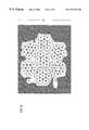
- the tension member 22is a single device that integrates a plurality of cords 26 within a common coating layer 28 .
- Each of the cords 26is formed from preferably seven twisted strands, each made up of seven twisted metallic wires.
- a high carbon steelis employed.
- the steelis preferably cold drawn and galvanized for the recognized properties of strength and corrosion resistance of such processes.
- the coating layeris preferably a polyurethane material which is ether based and includes a fire retardant composition.
- each strand 27 of a cord 26comprises seven wires with six of the wires 29 twisted around a center wire 31 .
- Each cord 26comprises one strand 27 a which is centrally located and six additional outer strands 27 b that are twisted around the central strand 27 a .
- the twisting pattern of the individual wires 29 that form the central strand 27 aare twisted in one direction around central wire 31 of central strand 27 a while the wires 29 of outer strands 27 b are twisted around the central wire 31 of the outer strands 27 b in the opposite direction.
- Outer strands 27 bare twisted around central strand 27 a in the same direction as the wires 29 are twisted around center wire 31 in strand 27 a .
- the individual strands in one embodimentcomprise the central wire 31 , in center strand 27 a , with the six twisted wires 29 twisting clockwise; the wires 29 in the outer strands 27 b twisting counterclockwise around their individual center wires 31 while at the cord 26 level the outer strands 27 b twist around the central strand 27 a in the clockwise direction.
- the directions of twistingimprove the characteristics of load sharing in all of the wires of the cord.
- wire 29 of a very small sizeEach wire 29 and 31 are less than 0.25 millimeters in diameter and preferably is in the range of about 0.10 millimeters to 0.20 millimeters in diameter. In a particular embodiment, the wires are of a diameter of 0.175 millimeters in diameter.
- the small sizes of the wires preferably employedcontribute to the benefit of the use of a sheave of smaller diameter. The smaller diameter wire can withstand the bending radius of a smaller diameter sheave (around 100 millimeters in diameter) without placing too much stress on the strands of the flat rope.
- the center wire 35 of the center strand 37 a of each cord 26employs a larger diameter.
- the center wire 35 of the center strand only of all cordswould be about 0.20-0.22 millimeters in diameter.
- the effect of such a center wire diameter changeis to reduce contact between wires 29 surrounding wire 35 as well as to reduce contact between strands 37 b which are twisted around strand 37 a .
- the diameter of cord 26will be slightly greater than the previous example of 1.6 millimeters.
- the concept of the second embodimentis expanded to further reduce wire-to-wire and strand-to-strand contact.
- Three distinct sizes of wiresare employed to construct the cords of the invention.
- the largest wireis the center wire 202 in the center strand 200 .
- the intermediate diameter wires 204are located around the center wire 202 of center strand 200 and therefore makeup a part of center strand 200 .
- This intermediate diameter wire 204is also the center wire 206 for all outer strands 210 .
- the smallest diameter wires employedare numbered 208 . These wrap each wire 206 in each outer strand 210 . All of the wires in the embodiment are still less than 0.25 mm in diameter.
- wires 202may be 0.21 mm; wires 204 may be 0.19 mm; wires 206 may be 0.19 mm; and wires 208 may be 0.175 mm.
- wires 204 and 206are of equivalent diameters and are numbered individually to provide locational information only. It is noted that the invention is not limited by wires 204 and 206 being identical in diameter. All of the diameters of wires provided are for example only and could be rearranged with the joining principle being that contact among the outer wires of the central strand is reduced; that contact among the outer wires of the outer strands is reduced and that contact among the outer strands is reduced. In the example provided, (only for purpose of example) the space obtained between the outer wires of outer strands is 0.014 mm.
- the cords 26are equal length, are approximately equally spaced widthwise within the coating layer 28 and are arranged linearly along the width dimension.
- the coating layer 28is formed from a polyurethane material, preferably a thermoplastic urethane, that is extruded onto and through the plurality of cords 26 in such a manner that each of the individual cords 26 is restrained against longitudinal movement relative to the other cords 26 .
- Transparent materialis an alternate embodiment which may be advantageous since it facilitates visual inspection of the flat rope. Structurally, of course, the color is irrelevant.
- Other materialsmay also be used for the coating layer 28 if they are sufficient to meet the required functions of the coating layer: traction, wear, transmission of traction loads to the cords 26 and resistance to environmental factors.
- thermoplastic urethaneif other materials are used which do not meet or exceed the mechanical properties of a thermoplastic urethane, then the additional benefit of the invention of dramatically reducing sheave diameter may not be fully achievable. With the thermoplastic urethane mechanical properties the sheave diameter is reducible to 100 millimeters or less.
- the coating layer 28defines an engagement surface 30 that is in contact with a corresponding surface of the traction sheave 24 .
- the tension member 22has a width w, measured laterally relative to the length of the tension member 22 , and a thickness t 1 , measured in the direction of bending of the tension member 22 about the sheave 24 .
- Each of the cords 26has a diameter d and are spaced apart by a distance s.
- An aspect ratio of onecorresponds to a circular cross-section, such as that common in conventional round ropes.
- the higher the aspect ratiothe more flat the tension member 22 is in cross-section.
- Flattening out the tension member 22minimizes the thickness t 1 and maximizes the width w of the tension member 22 without sacrificing cross-sectional area or load carrying capacity.
- This configurationresults in distributing the rope pressure across the width of the tension member 22 and reduces the maximum rope pressure relative to a round rope of comparable cross-sectional area and load carrying capacity. As shown in FIG.
- the aspect ratiois greater than five. Although shown as having an aspect ratio greater than five, it is believed that benefits will result from tension members having aspect ratios greater than one, and particularly for aspect ratios greater than two.
- the separation s between adjacent cords 26is dependant upon the materials and manufacturing processes used in the tension member 22 and the distribution of rope stress across the tension member 22 . For weight considerations, it is desirable to minimize the spacing s between adjacent cords 26 , thereby reducing the amount of coating material between the cords 26 . Taking into account rope stress distribution, however, may limit how close the cords 26 may be to each other in order to avoid excessive stress in the coating layer 28 between adjacent cords 26 . Based on these considerations, the spacing may be optimized for the particular load carrying requirements.
- the thickness t 2 of the coating layer 28is dependent upon the rope stress distribution and the wear characteristics of the coating layer 28 material. As before, it is desirable to avoid excessive stress in the coating layer 28 while providing sufficient material to maximize the expected life of the tension member 22 .
- the thickness t 3 of the coating layer 28is dependant upon the use of the tension member 22 . As illustrated in FIG. 1, the tension member 22 travels over a single sheave 24 and therefore the top surface 32 does not engage the sheave 24 . In this application, the thickness t 3 may be very thin, although it must be sufficient to withstand the strain as the tension member 22 travels over the sheave 24 . It may also be desirable to groove the tension member surface 32 to reduce tension in the thickness t 3 . On the other hand, a thickness t 3 equivalent to that of t 2 may be required if the tension member 22 is used in an elevator system that requires reverse bending of the tension member 22 about a second sheave. In this application, both the upper 32 and lower surface 30 of the tension member 22 is an engagement surface and subject to the same requirement of wear and stress.
- the diameter d of the individual cords 26 and the number of cords 26is dependent upon the specific application. It is desirable to maintain the thickness d as small as possible, as hereinbefore discussed, in order to maximize the flexibility and minimize the stress in the cords 26 .
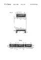
- the traction sheave 24includes a base 40 and a liner 42 .
- the base 40is formed from cast iron and includes a pair of rims 44 disposed on opposite sides of the sheave 24 to form a groove 46 .
- the liner 42includes a base 48 having a traction surface 50 and a pair of flanges 52 that are supported by the rims 44 of the sheave 24 .
- the liner 42is formed from a polyurethane material, such as that described in commonly owned U.S. Pat. No. 5,112,933, or any other suitable material providing the desired traction with the engagement surface 30 of the coating layer 28 and wear characteristics.
- the sheave liner 42wear rather than the sheave 24 or the tension member 22 due to the cost associated with replacing the tension member 22 or sheave 24 .
- the liner 42performs the function of a sacrificial layer in the traction drive 18 .
- the liner 42is retained, either by bonding or any other conventional method, within the groove 46 and defines the traction surface 50 for receiving the tension member 22 .
- the traction surface 50has a diameter D. Engagement between the traction surface 50 and the engagement surface 30 provides the traction for driving the elevator system 12 .
- the diameter of a sheave for use with the traction member described hereinaboveis dramatically reduced from prior art sheave diameters.
- sheaves to be employed with the flat rope of the inventionmay be reduced in diameter to 100 mm or less.
- a diameter reduction of the sheaveallows for the employment of a much smaller machine.
- machine sizesmay fall to 1 ⁇ 4 of their conventional size in for example low rise gearless applications for a typical 8 passenger duty elevators. This is because torque requirements would be cut to about 1 ⁇ 4 with a 100 mm sheave and the rpm of the motor would be increased. Cost for the machines indicated accordingly falls.
- the tension member 22may be used with a sheave not having a liner 42 .
- the liner 42may be replaced by coating the sheave with a layer of a selected material, such as polyurethane, or the sheave may be formed or molded from an appropriate synthetic material. These alternatives may prove cost effective if it is determined that, due to the diminished size of the sheave, it may be less expensive to simply replace the entire sheave rather than replacing sheave liners.
- the shape of the sheave 24 and liner 42defines a space 54 into which the tension member 22 is received.
- the rims 44 and the flanges 52 of the liner 42provide a boundary on the engagement between the tension member 22 and the sheave 24 and guide the engagement to avoid the tension member 22 becoming disengaged from the sheave 24 .
- FIG. 3An alternate embodiment of the traction drive 18 is illustrated in FIG. 3 .
- the traction drive 18includes three tension members 56 and a traction sheave 58 .
- Each of the tension members 56is similar in configuration to the tension member 22 described above with respect to FIGS. 1 and 2.
- the traction sheave 58includes a base 62 , a pair of rims 64 disposed on opposite side of the sheave 58 , a pair of dividers 66 , and three liners 68 .
- the dividers 66are laterally spaced from the rims 64 and from each other to define three grooves 70 that receive the liners 68 .
- each liner 68includes a base 72 that defines a traction surface 74 to receive one of the tension members 56 and a pair of flanges 76 that abut the rims 64 or dividers 66 . Also as in FIG. 2, the liner 42 is wide enough to allow a space 54 to exist between the edges of the tension member and the flanges 76 of the liner 42 .
- FIGS. 4 and 5illustrate Alternative construction for the traction drive 18 are illustrated in FIGS. 4 and 5.
- FIG. 4illustrates a sheave 86 having a convex shaped traction surface 88 .
- the shape of the traction surface 88urges the flat tension member 90 to remain centered during operation.
- FIG. 5illustrates a tension member 92 having a contoured engagement surface 94 that is defined by the encapsulated cords 96 .
- the traction sheave 98includes a liner 100 that has a traction surface 102 that is contoured to complement the contour of the tension member 92 .
- the complementary configurationprovides guidance to the tension member 92 during engagement and, in addition, increases the traction forces between the tension member 92 and the traction sheave 98 .
- tension members and traction drivesmay result in significant reductions in maximum rope pressure, with corresponding reductions in sheave diameter and torque requirements.
- the reduction in maximum rope pressureresults from the cross-sectional area of the tension member having an aspect ratio of greater than one.
- the calculation for approximate maximum rope pressureis determined as follows:
- the factor of (4/ ⁇ )results in an increase of at least 27% in maximum rope pressure, assuming that the diameters and tension levels are comparable. More significantly, the width w is much larger than the cord diameter d, which results in greatly reduced maximum rope pressure. If the conventional rope grooves are undercut, the maximum rope pressure is even greater and therefore greater relative reductions in the maximum rope pressure may be achieved using a flat tension member configuration.
- Another advantage of the tension member according to the present inventionis that the thickness t 1 of the tension member may be much smaller than the diameter d of equivalent load carrying capacity round ropes. This enhances the flexibility of the tension member as compared to conventional ropes.
Landscapes
- Engineering & Computer Science (AREA)
- Structural Engineering (AREA)
- Civil Engineering (AREA)
- Mechanical Engineering (AREA)
- Automation & Control Theory (AREA)
- Lift-Guide Devices, And Elevator Ropes And Cables (AREA)
- Cage And Drive Apparatuses For Elevators (AREA)
- Ropes Or Cables (AREA)
Abstract
Description
This is a continuation-in-part of U.S. Ser. No. 09/031,108 filed Feb. 26, 1998, now U.S. Pat. No. 6,401,871 the entirety of which is incorporated herein by reference.
The present invention relates to elevator systems, and more particularly to tension members for such elevator systems.
A conventional traction elevator system includes a car, a counterweight, two or more ropes interconnecting the car and counterweight, a traction sheave to move the ropes, and a machine to rotate the traction sheave. The ropes are formed from laid or twisted steel wire and the sheave is formed from cast iron. The machine may be either a geared or gearless machine. A geared machine permits the use of higher speed motor, which is more compact and less costly, but requires additional maintenance and space.
Although conventional round steel ropes and cast iron sheaves have proven very reliable and cost effective, there are limitations on their use. One such limitation is the traction forces between the ropes and the sheave. These traction forces may be enhanced by increasing the wrap angle of the ropes or by undercutting the grooves in the sheave. Both techniques reduce the durability of the ropes, however, as a result of the increased wear (wrap angle) or the increased rope pressure (undercutting). Another method to increase the traction forces is to use liners formed from a synthetic material in the grooves of the sheave. The liners increase the coefficient of friction between the ropes and sheave while at the same time minimizing the wear of the ropes and sheave.
Another limitation on the use of round steel ropes is the flexibility and fatigue characteristics of round steel wire ropes. Elevator safety codes today require that each steel rope have a minimum diameter d (dmin=8 mm for CEN; dmin=9.5 mm (⅜″) for ANSI) and that the D/d ratio for traction elevators be greater than or equal y (D/d≧40), where D is the diameter of the sheave. This results in the diameter D for the sheave being at least 320 mm (380 mm for ANSI). The larger the sheave diameter D, the greater torque required from the machine to drive the elevator system.
Another drawback of conventional round ropes is that the higher the rope pressure, the shorter the life of the rope. Rope pressure (Prope) is generated as the rope travels over the sheave and is directly proportional to the tension (F) in the rope and inversely proportional to the sheave diameter D and the rope diameter d (Prope˜F/(Dd). In addition, the shape of the sheave grooves, including such traction enhancing techniques as undercutting the sheave grooves, further increases the maximum rope pressure to which the rope is subjected.
The above art notwithstanding, scientists and engineers under the direction of Applicants' Assignee are working to develop more efficient and durable methods and apparatus to drive elevator systems.
According to the present invention, a tension member for an elevator has an aspect ratio of greater than one, where aspect ratio is defined as the ratio of tension member width w to thickness t (Aspect Ratio˜w/t).
A principal feature of the present invention is the flatness of the tension member. The increase in aspect ratio results in a tension member that has an engagement surface, defined by the width dimension, that is optimized to distribute the rope pressure. Therefore, the maximum pressure is minimized within the tension member. In addition, by increasing the aspect ratio relative to a round rope, which has an aspect ratio equal to one, the thickness of the tension member may be reduced while maintaining a constant cross-sectional area of the tension member.
According further to the present invention, the tension member includes a plurality of individual load carrying cords encased within a common layer of coating. The coating layer separates the individual cords and defines an engagement surface for engaging a traction sheave.
As a result of the configuration of the tension member, the rope pressure may be distributed more uniformly throughout the tension member. As a result, the maximum rope pressure is significantly reduced as compared to a conventionally roped elevator having a similar load carrying capacity. Furthermore, the effective rope diameter ‘d’ (measured in the bending direction) is reduced for the equivalent load bearing capacity. Therefore, smaller values for the sheave diameter ‘D’ may be attained without a reduction in the D/d ratio. In addition, minimizing the diameter D of the sheave permits the use of less costly, more compact, high speed motors as the drive machine without the need for a gearbox.
In a particular embodiment of the present invention, the individual cords are formed from strands of metallic material. By incorporating cords having the weight, strength, durability and, in particular, the flexibility characteristics of appropriately sized and constructed materials into the tension member of the present invention, the acceptable traction sheave diameter may be further reduced while maintaining the maximum rope pressure within acceptable limits. As stated previously, smaller sheave diameters reduce the required torque of the machine driving the sheave and increase the rotational speed. Therefore, smaller and less costly machines may be used to drive the elevator system.
In a further particular embodiment of the present invention, a traction drive for an elevator system includes a tension member having an aspect ratio greater than one and a traction sheave having a traction surface configured to receive the tension member. The tension member includes an engagement surface defined by the width dimension of the tension member. The traction surface of the sheave and the engagement surface are complementarily contoured to provide traction and to guide the engagement between the tension member and the sheave. In an alternate configuration, the traction drive includes a plurality of tension members engaged with the sheave and the sheave includes a pair of rims disposed on opposite sides of the sheave and one or more dividers disposed between adjacent tension members. The pair of rims and dividers perform the function of guiding the tension member to prevent gross alignment problems in the event of slack rope conditions, etc.
In a still further embodiment, the traction surface of the sheave is defined by a material that optimizes the traction forces between the sheave and the tension member and minimizes the wear of the tension member. In one configuration, the traction surface is integral to a sheave liner that is disposed on the sheave. In another configuration, the traction surface is defined by a coating layer that is bonded to the traction sheave. In a still further configuration, the traction sheave is formed from the material that defines the traction surface.
Although described herein as primarily a traction device for use in an elevator application having a traction sheave, the tension member may be useful and have benefits in elevator applications that do not use a traction sheave to drive the tension member, such as indirectly roped elevator systems, linear motor driven elevator systems, or self-propelled elevators having a counterweight. In these applications, the reduced size of the sheave may be useful in order to reduce space requirements for the elevator system. The foregoing and other objects, features and advantages of the present invention become more apparent in light of the following detailed description of the exemplary embodiments thereof, as illustrated in the accompanying drawings.
FIG. 1 is perspective view of an elevator system having a traction drive according to the present invention;
FIG. 2 is a sectional, side view of the traction drive, showing a tension member and a sheave;
FIG. 3 is a sectional, side view of an alternate embodiment showing a plurality of tension members;
FIG. 4 is another alternate embodiment showing a traction sheave having an convex shape to center the tension member;
FIG. 5 is a further alternate embodiment showing a traction sheave and tension member having complementary contours to enhance traction and to guide the engagement between the tension member and the sheave;
FIG. 6 is a magnified cross sectional view of a single cord of the invention having six strands twisted around a central stand;
FIG. 7 is a magnified cross sectional view of an alternate single cord of the invention;
FIG. 8 is a magnified cross sectional view of another alternate embodiment of the invention; and
FIG. 9 is a schematic cross sectional view of a flat rope to illustrate various dimensional characteristics thereof.
Illustrated in FIG. 1 is atraction elevator system 12. Theelevator system 12 includes acar 14, acounterweight 16, atraction drive 18, and amachine 20. The traction drive18 includes atension member 22, interconnecting thecar 14 andcounterweight 16, and atraction sheave 24. Thetension member 22 is engaged with thesheave 24 such that rotation of thesheave 24 moves thetension member 22, and thereby thecar 14 andcounterweight 16. Themachine 20 is engaged with thesheave 24 to rotate thesheave 24. Although shown as an gearedmachine 20, it should be noted that this configuration is for illustrative purposes only, and the present invention may be used with geared or gearless machines.
Thetension member 22 andsheave 24 are illustrated in more detail in FIG.2. Thetension member 22 is a single device that integrates a plurality ofcords 26 within acommon coating layer 28. Each of thecords 26 is formed from preferably seven twisted strands, each made up of seven twisted metallic wires. In a preferred embodiment of the invention a high carbon steel is employed. The steel is preferably cold drawn and galvanized for the recognized properties of strength and corrosion resistance of such processes. The coating layer is preferably a polyurethane material which is ether based and includes a fire retardant composition.
In a preferred embodiment, referring to FIG. 6, each strand27 of acord 26 comprises seven wires with six of thewires 29 twisted around acenter wire 31. Eachcord 26, comprises onestrand 27awhich is centrally located and six additionalouter strands 27bthat are twisted around thecentral strand 27a. Preferably, the twisting pattern of theindividual wires 29 that form thecentral strand 27aare twisted in one direction aroundcentral wire 31 ofcentral strand 27awhile thewires 29 ofouter strands 27bare twisted around thecentral wire 31 of theouter strands 27bin the opposite direction.Outer strands 27bare twisted aroundcentral strand 27ain the same direction as thewires 29 are twisted aroundcenter wire 31 instrand 27a. For example, the individual strands in one embodiment comprise thecentral wire 31, incenter strand 27a, with the sixtwisted wires 29 twisting clockwise; thewires 29 in theouter strands 27btwisting counterclockwise around theirindividual center wires 31 while at thecord 26 level theouter strands 27btwist around thecentral strand 27ain the clockwise direction. The directions of twisting improve the characteristics of load sharing in all of the wires of the cord.
It is important to the success of the invention to employwire 29 of a very small size. Eachwire small cords 26, preferably about 1.6 millimeters in total diameter in this particular embodiment of the invention, into the flat rope elastomer, the pressure on each cord is significantly diminished over prior art ropes. Cord pressure is decreased at least as n−½ with n being the number of parallel cords in the flat rope, for a given load and wire cross section.
In an alternate embodiment, referring to FIG. 7, thecenter wire 35 of thecenter strand 37aof eachcord 26 employs a larger diameter. For example, if thewires 29 of the previous embodiment (0.175 millimeters) are employed, thecenter wire 35 of the center strand only of all cords would be about 0.20-0.22 millimeters in diameter. The effect of such a center wire diameter change is to reduce contact betweenwires 29 surroundingwire 35 as well as to reduce contact betweenstrands 37bwhich are twisted aroundstrand 37a. In such an embodiment the diameter ofcord 26 will be slightly greater than the previous example of 1.6 millimeters.
In a third embodiment of the invention, referring to FIG. 8, the concept of the second embodiment is expanded to further reduce wire-to-wire and strand-to-strand contact. Three distinct sizes of wires are employed to construct the cords of the invention. In this embodiment the largest wire is thecenter wire 202 in thecenter strand 200. Theintermediate diameter wires 204 are located around thecenter wire 202 ofcenter strand 200 and therefore makeup a part ofcenter strand 200. Thisintermediate diameter wire 204 is also thecenter wire 206 for allouter strands 210. The smallest diameter wires employed are numbered208. These wrap eachwire 206 in eachouter strand 210. All of the wires in the embodiment are still less than 0.25 mm in diameter. In a representative embodiment,wires 202 may be 0.21 mm;wires 204 may be 0.19 mm;wires 206 may be 0.19 mm; andwires 208 may be 0.175 mm. It will be appreciated that in thisembodiment wires wires
Thecords 26 are equal length, are approximately equally spaced widthwise within thecoating layer 28 and are arranged linearly along the width dimension. Thecoating layer 28 is formed from a polyurethane material, preferably a thermoplastic urethane, that is extruded onto and through the plurality ofcords 26 in such a manner that each of theindividual cords 26 is restrained against longitudinal movement relative to theother cords 26. Transparent material is an alternate embodiment which may be advantageous since it facilitates visual inspection of the flat rope. Structurally, of course, the color is irrelevant. Other materials may also be used for thecoating layer 28 if they are sufficient to meet the required functions of the coating layer: traction, wear, transmission of traction loads to thecords 26 and resistance to environmental factors. It should further be understood that if other materials are used which do not meet or exceed the mechanical properties of a thermoplastic urethane, then the additional benefit of the invention of dramatically reducing sheave diameter may not be fully achievable. With the thermoplastic urethane mechanical properties the sheave diameter is reducible to 100 millimeters or less. Thecoating layer 28 defines anengagement surface 30 that is in contact with a corresponding surface of thetraction sheave 24.
As shown more clearly in FIG. 9, thetension member 22 has a width w, measured laterally relative to the length of thetension member 22, and a thickness t1, measured in the direction of bending of thetension member 22 about thesheave 24. Each of thecords 26 has a diameter d and are spaced apart by a distance s. In addition, the thickness of thecoating layer 28 between thecords 26 and theengagement surface 30 is defined as t2 and between thecords 26 and the opposite surface is defined as t3, such that t1=t2+t3+d.
The overall dimensions of thetension member 22 results in a cross-section having an aspect ratio of much greater than one, where aspect ratio is defined as the ratio of width w to thickness t1 or (Aspect Ratio=w/t1). An aspect ratio of one corresponds to a circular cross-section, such as that common in conventional round ropes. The higher the aspect ratio, the more flat thetension member 22 is in cross-section. Flattening out thetension member 22 minimizes the thickness t1 and maximizes the width w of thetension member 22 without sacrificing cross-sectional area or load carrying capacity. This configuration results in distributing the rope pressure across the width of thetension member 22 and reduces the maximum rope pressure relative to a round rope of comparable cross-sectional area and load carrying capacity. As shown in FIG. 2, for thetension member 22 having fiveindividual cords 26 disposed within thecoating layer 28, the aspect ratio is greater than five. Although shown as having an aspect ratio greater than five, it is believed that benefits will result from tension members having aspect ratios greater than one, and particularly for aspect ratios greater than two.
The separation s betweenadjacent cords 26 is dependant upon the materials and manufacturing processes used in thetension member 22 and the distribution of rope stress across thetension member 22. For weight considerations, it is desirable to minimize the spacing s betweenadjacent cords 26, thereby reducing the amount of coating material between thecords 26. Taking into account rope stress distribution, however, may limit how close thecords 26 may be to each other in order to avoid excessive stress in thecoating layer 28 betweenadjacent cords 26. Based on these considerations, the spacing may be optimized for the particular load carrying requirements.
The thickness t2 of thecoating layer 28 is dependent upon the rope stress distribution and the wear characteristics of thecoating layer 28 material. As before, it is desirable to avoid excessive stress in thecoating layer 28 while providing sufficient material to maximize the expected life of thetension member 22.
The thickness t3 of thecoating layer 28 is dependant upon the use of thetension member 22. As illustrated in FIG. 1, thetension member 22 travels over asingle sheave 24 and therefore thetop surface 32 does not engage thesheave 24. In this application, the thickness t3 may be very thin, although it must be sufficient to withstand the strain as thetension member 22 travels over thesheave 24. It may also be desirable to groove thetension member surface 32 to reduce tension in the thickness t3. On the other hand, a thickness t3 equivalent to that of t2 may be required if thetension member 22 is used in an elevator system that requires reverse bending of thetension member 22 about a second sheave. In this application, both the upper32 andlower surface 30 of thetension member 22 is an engagement surface and subject to the same requirement of wear and stress.
The diameter d of theindividual cords 26 and the number ofcords 26 is dependent upon the specific application. It is desirable to maintain the thickness d as small as possible, as hereinbefore discussed, in order to maximize the flexibility and minimize the stress in thecords 26.
Referring back to FIG. 2, thetraction sheave 24 includes abase 40 and aliner 42. Thebase 40 is formed from cast iron and includes a pair ofrims 44 disposed on opposite sides of thesheave 24 to form agroove 46. Theliner 42 includes a base48 having atraction surface 50 and a pair offlanges 52 that are supported by therims 44 of thesheave 24. Theliner 42 is formed from a polyurethane material, such as that described in commonly owned U.S. Pat. No. 5,112,933, or any other suitable material providing the desired traction with theengagement surface 30 of thecoating layer 28 and wear characteristics. Within thetraction drive 18, it is desired that thesheave liner 42 wear rather than thesheave 24 or thetension member 22 due to the cost associated with replacing thetension member 22 orsheave 24. As such, theliner 42 performs the function of a sacrificial layer in thetraction drive 18. Theliner 42 is retained, either by bonding or any other conventional method, within thegroove 46 and defines thetraction surface 50 for receiving thetension member 22. Thetraction surface 50 has a diameter D. Engagement between thetraction surface 50 and theengagement surface 30 provides the traction for driving theelevator system 12. The diameter of a sheave for use with the traction member described hereinabove is dramatically reduced from prior art sheave diameters. More particularly, sheaves to be employed with the flat rope of the invention may be reduced in diameter to 100 mm or less. As will be immediately recognized by those skilled in the art, such a diameter reduction of the sheave allows for the employment of a much smaller machine. In fact, machine sizes may fall to ¼ of their conventional size in for example low rise gearless applications for a typical 8 passenger duty elevators. This is because torque requirements would be cut to about ¼ with a 100 mm sheave and the rpm of the motor would be increased. Cost for the machines indicated accordingly falls.
Although illustrated as having aliner 42, it should be apparent to those skilled in the art that thetension member 22 may be used with a sheave not having aliner 42. As an alternative, theliner 42 may be replaced by coating the sheave with a layer of a selected material, such as polyurethane, or the sheave may be formed or molded from an appropriate synthetic material. These alternatives may prove cost effective if it is determined that, due to the diminished size of the sheave, it may be less expensive to simply replace the entire sheave rather than replacing sheave liners.
The shape of thesheave 24 andliner 42 defines aspace 54 into which thetension member 22 is received. Therims 44 and theflanges 52 of theliner 42 provide a boundary on the engagement between thetension member 22 and thesheave 24 and guide the engagement to avoid thetension member 22 becoming disengaged from thesheave 24.
An alternate embodiment of thetraction drive 18 is illustrated in FIG.3. In this embodiment, thetraction drive 18 includes three tension members56 and atraction sheave 58. Each of the tension members56 is similar in configuration to thetension member 22 described above with respect to FIGS. 1 and 2. Thetraction sheave 58 includes abase 62, a pair ofrims 64 disposed on opposite side of thesheave 58, a pair of dividers66, and threeliners 68. The dividers66 are laterally spaced from therims 64 and from each other to define threegrooves 70 that receive theliners 68. As with theliner 42 described with respect to FIG. 2, eachliner 68 includes a base72 that defines atraction surface 74 to receive one of the tension members56 and a pair offlanges 76 that abut therims 64 or dividers66. Also as in FIG. 2, theliner 42 is wide enough to allow aspace 54 to exist between the edges of the tension member and theflanges 76 of theliner 42.
Alternative construction for thetraction drive 18 are illustrated in FIGS. 4 and 5. FIG. 4 illustrates asheave 86 having a convex shapedtraction surface 88. The shape of thetraction surface 88 urges theflat tension member 90 to remain centered during operation. FIG. 5 illustrates atension member 92 having a contouredengagement surface 94 that is defined by the encapsulatedcords 96. Thetraction sheave 98 includes aliner 100 that has atraction surface 102 that is contoured to complement the contour of thetension member 92. The complementary configuration provides guidance to thetension member 92 during engagement and, in addition, increases the traction forces between thetension member 92 and thetraction sheave 98.
Use of tension members and traction drives according to the present invention may result in significant reductions in maximum rope pressure, with corresponding reductions in sheave diameter and torque requirements. The reduction in maximum rope pressure results from the cross-sectional area of the tension member having an aspect ratio of greater than one. The calculation for approximate maximum rope pressure (slightly higher due to discreteness of individual cords) is determined as follows:
Where F is the maximum tension in the tension member. For a round rope within a round groove, the calculation of maximum rope pressure is determined as follows:
The factor of (4/π) results in an increase of at least 27% in maximum rope pressure, assuming that the diameters and tension levels are comparable. More significantly, the width w is much larger than the cord diameter d, which results in greatly reduced maximum rope pressure. If the conventional rope grooves are undercut, the maximum rope pressure is even greater and therefore greater relative reductions in the maximum rope pressure may be achieved using a flat tension member configuration. Another advantage of the tension member according to the present invention is that the thickness t1 of the tension member may be much smaller than the diameter d of equivalent load carrying capacity round ropes. This enhances the flexibility of the tension member as compared to conventional ropes.
Although the invention has been shown and described with respect to exemplary embodiments thereof, it should be understood by those skilled in the art that various changes, omissions, and additions may be made thereto, without departing from the spirit and scope of the invention.
Claims (28)
1. A tension member for providing lifting force to a car of an elevator system, comprising:
a plurality of discrete cords, constructed from a plurality of individual wires, wherein all wires are less than 0.25 millimeters in diameter, said plurality of cords being arranged side-by-side;
a coating layer substantially enveloping said plurality of cords and having an aspect ratio defined as the ratio of width w relative to thickness t, greater than one.
2. A tension member according toclaim 1 wherein said plurality of wires are in a twisted pattern creating strands of several wires and a center wire.
3. A tension member according toclaim 2 wherein said several wires and said center wire is seven wires.
4. A tension member according toclaim 2 wherein said strand pattern is defined as said several wires twisted around said one center wire.
5. A tension member according toclaim 4 , wherein the coating layer is formed from an elastomer.
6. A tension member according toclaim 4 wherein said several wires is six wires.
7. A tension member according toclaim 4 wherein said plurality of cords are each in a pattern comprising several strands around a center strand.
8. A tension member according toclaim 7 wherein said plurality of cords each comprise seven strands.
9. A tension member according toclaim 7 wherein said cord pattern is several outer strands twisted around said center strand.
10. A tension member according toclaim 9 wherein said center strand comprises said several wires twisted around said one center wire in a first direction and said outer strands each comprise said several wires twisted around said one center wire in a second direction and said outer strands are twisted around said center strand in said first direction.
11. A tension member according toclaim 9 wherein said center wire in said center strand is of a larger diameter than all other wires in each cord of said plurality of cords.
12. A tension member according toclaim 9 wherein each said center wire of each strand is larger than all wires twisted therearound.
13. A tension member according toclaim 12 wherein said center wire of said center strand is larger than said center wire of each said outer strands.
14. A tension member according toclaim 9 wherein said cord pattern is six strands twisted around said center strand.
15. A tension member according toclaim 14 wherein said center wire of each strand is larger than all wires twisted therearound.
16. A tension member according toclaim 14 wherein said center wire of said center strand is larger than said center wire of each of said six strands.
17. A tension member according toclaim 1 wherein said wires diameters are less than 0.20 millimeters.
18. A tension member according toclaim 1 wherein said cords are arranged in spaced relation to each other.
19. A tension member according toclaim 1 wherein the aspect ratio is greater than or equal to two.
20. A tension member according toclaim 1 wherein said coating layer is an elastomer.
21. A tension member according toclaim 20 wherein said elastomer is a thermoplastic urethane.
22. A tension member according toclaim 21 wherein said urethane is transparent.
23. A tension member according toclaim 1 wherein said cords are steel.
24. A tension member according toclaim 1 , wherein the sheave includes an engagement surface, and wherein the engagement surface of the tension member is contoured to complement the engagement surface of the sheave.
25. A tension member according toclaim 1 wherein said coating layer defines a single engagement surface for the plurality of individual cords.
26. A tension member according toclaim 25 wherein said coating layer extends widthwise such that the engagement surface extends about the plurality of individual cords.
27. A tension member according toclaim 25 wherein said engagement surface is shaped by an outer contour of said plurality of cords.
28. A tension member according toclaim 25 , wherein said engagement surface is contoured to complement an engagement surface of a sheave.
Priority Applications (140)
| Application Number | Priority Date | Filing Date | Title |
|---|---|---|---|
| US09/218,990US6739433B1 (en) | 1998-02-26 | 1998-12-22 | Tension member for an elevator |
| JP2000533361AJP2002504472A (en) | 1998-02-26 | 1999-02-19 | Elevator device without machine room with elevator machine mounted in elevator car |
| PT99908282TPT1060305E (en) | 1998-02-26 | 1999-02-19 | ELEVATOR SYSTEMS |
| PCT/US1999/003658WO1999043885A1 (en) | 1998-02-26 | 1999-02-19 | Tension member for an elevator |
| DE29924762UDE29924762U1 (en) | 1998-02-26 | 1999-02-19 | Elevator system having drive motor located between elevator car and hoistway side wall |
| DE29924759UDE29924759U1 (en) | 1998-02-26 | 1999-02-19 | Elevator system having drive motor located between elevator car and hoistway side wall |
| KR1020007009389AKR20010041289A (en) | 1998-02-26 | 1999-02-19 | Elevator system with overhead drive motor |
| EP99907157AEP1028911B1 (en) | 1998-02-26 | 1999-02-19 | Flat cable connecting device |
| EP99907158AEP1064216A2 (en) | 1998-02-26 | 1999-02-19 | Dual sheave rope climber using flat flexible ropes |
| KR1020007009504AKR100607631B1 (en) | 1998-02-26 | 1999-02-19 | Tension member for an elevator |
| PT99908278TPT1056679E (en) | 1998-02-26 | 1999-02-19 | LIFTING SYSTEM WITHOUT HOUSE MACHINES WITH A LIFTING MACHINE MOUNTED IN A LIFT CABIN |
| ES07010560.6TES2502843T3 (en) | 1998-02-26 | 1999-02-19 | Elevator system that has the drive motor located at the bottom of the elevator shaft |
| ES06008461.3TES2527100T3 (en) | 1998-02-26 | 1999-02-19 | Elevator system with raised drive motor |
| PT99908296TPT1042209E (en) | 1998-02-26 | 1999-02-19 | LIFTING SYSTEM WHICH HAS THE DRIVE ENGINE LOCATED NEXT TO THE LIFT DOOR DOOR |
| ES99907157TES2267249T3 (en) | 1998-02-26 | 1999-02-19 | CONNECTION DEVICE OF A FLAT CABLE. |
| PCT/US1999/003643WO1999043590A1 (en) | 1998-02-26 | 1999-02-19 | Traction elevator system using a flexible, flat rope and a permanent magnet machine |
| KR1020007009386AKR20010041286A (en) | 1998-02-26 | 1999-02-19 | Dual sheave rope climber using flat flexible ropes |
| JP2000533617AJP4763127B2 (en) | 1998-02-26 | 1999-02-19 | Elevator tension member |
| EP07010560.6AEP1911715B1 (en) | 1998-02-26 | 1999-02-19 | Elevator system having drive motor located at the bottom portion of the hoistway |
| EP99908278AEP1056679B1 (en) | 1998-02-26 | 1999-02-19 | Machine-roomless elevator system with an elevator machine mounted on an elevator car |
| PT99908279TPT1056675E (en) | 1998-02-26 | 1999-02-19 | Elevator system having drive motor located between elevator car and hoistway sidewall |
| DE69941801TDE69941801D1 (en) | 1998-02-26 | 1999-02-19 | Belt lift with drive on the counterweight |
| BR9908304-3ABR9908304A (en) | 1998-02-26 | 1999-02-19 | Double pulley cable lift using flat flexible cables |
| EP05017479AEP1604938B1 (en) | 1998-02-26 | 1999-02-19 | Elevator system having drive motor located adjacent to hoistway door |
| JP2000533359AJP2002504471A (en) | 1998-02-26 | 1999-02-19 | Elevator system with overhead mounted drive motor |
| CNB998033626ACN1267604C (en) | 1998-02-26 | 1999-02-19 | Tensions, traction drives and pulleys and pulley bushings for elevators |
| EP99936066AEP1023236B2 (en) | 1998-02-26 | 1999-02-19 | Traction elevator system using a flexible, flat rope and a permanent magnet machine |
| PCT/US1999/003645WO1999043589A1 (en) | 1998-02-26 | 1999-02-19 | Elevator system having drive motor located between elevator car and hoistway sidewall |
| KR1020007009432AKR100567688B1 (en) | 1998-02-26 | 1999-02-19 | Belt climbing elevator with drive in counterweight |
| BR9908230-6ABR9908230A (en) | 1998-02-26 | 1999-02-19 | Elevator system with suspended drive motor |
| PT60084613TPT1676807E (en) | 1998-02-26 | 1999-02-19 | Elevator system with overhead drive motor |
| EP99936069AEP1097102A1 (en) | 1998-02-26 | 1999-02-19 | Belt-climbing elevator having drive in counterweight and common drive and suspension rope |
| DE69933107TDE69933107T2 (en) | 1998-02-26 | 1999-02-19 | CABLE CONNECTION ARRANGEMENT |
| ES06014420TES2458565T3 (en) | 1998-02-26 | 1999-02-19 | Cable connection device |
| ES99908279TES2272055T3 (en) | 1998-02-26 | 1999-02-19 | ELEVATOR SYSTEM THAT HAS THE DRIVE MOTOR SITUATED BETWEEN THE ELEVATOR HOOD AND THE SIDE WALL OF THE ELEVATOR BOX. |
| DE29924751UDE29924751U1 (en) | 1998-02-26 | 1999-02-19 | Flat flexible cable for hoisting an elevator |
| PCT/US1999/003646WO1999043600A1 (en) | 1998-02-26 | 1999-02-19 | Elevator system having drive motor located at the bottom portion of the hoistway |
| EP06008461.3AEP1676807B1 (en) | 1998-02-26 | 1999-02-19 | Elevator system with overhead drive motor |
| CN 99805444CN1299333A (en) | 1998-02-26 | 1999-02-19 | Belt-climbing elevator having drive in counterweight |
| PT99936068TPT1097101E (en) | 1998-02-26 | 1999-02-19 | Elevator system having drive motor located at the bottom portion of the hoistway |
| EP99908279AEP1056675B1 (en) | 1998-02-26 | 1999-02-19 | Elevator system having drive motor located between elevator car and hoistway sidewall |
| BR9908227-6ABR9908227A (en) | 1998-02-26 | 1999-02-19 | Belt lift with a drive counterweight |
| CNB998033642ACN1329273C (en) | 1998-02-26 | 1999-02-19 | Elevator system with overhead drive motor |
| PT99936066TPT1023236E (en) | 1998-02-26 | 1999-02-19 | A TRACCAO LIFTING SYSTEM USING A FLAT AND FLEXIBLE CABLE AND A PERMANENT IMA MACHINE |
| DE29924745UDE29924745U1 (en) | 1998-02-26 | 1999-02-19 | Directional match of flat ropes for elevators |
| DE29924747UDE29924747U1 (en) | 1998-02-26 | 1999-02-19 | Elevator system with drive motor between elevator car and elevator shaft side wall |
| PCT/US1999/003648WO1999043593A1 (en) | 1998-02-26 | 1999-02-19 | Elevator system with overhead drive motor |
| EP03024661.5AEP1391413B2 (en) | 1998-02-26 | 1999-02-19 | Traction elevator system using a flexible flat rope |
| HK02100741.0AHK1039105B (en) | 1998-02-26 | 1999-02-19 | Elevator system with overhead drive motor |
| PT99908277TPT1056676E (en) | 1998-02-26 | 1999-02-19 | Belt-climbing elevator having drive in counterweight |
| CNB998054437ACN100347068C (en) | 1998-02-26 | 1999-02-19 | Elevator system having drive motor located between elevator car and hoistway sidemall |
| PT99936067TPT1066213E (en) | 1998-02-26 | 1999-02-19 | LIFTING SYSTEM WITH HEIGHT MOUNTED DRIVE ENGINE |
| ES99908296TES2244176T3 (en) | 1998-02-26 | 1999-02-19 | ASCENT SYSTEM WITH DRIVE MOTOR LOCATED ADJACENT TO DOOR OF THE LIFT BOX. |
| CN 99803365CN1342130A (en) | 1998-02-26 | 1999-02-19 | Dual sheave rope climber using flat flexible ropes |
| PT99907157TPT1028911E (en) | 1998-02-26 | 1999-02-19 | Flat cable connecting device |
| ES99936066TES2211130T5 (en) | 1998-02-26 | 1999-02-19 | TRACTION ELEVATION SYSTEM THAT USES A FLEXIBLE AND FLAT CABLE, AND A PERMANENT MAGNET MACHINE. |
| BR9908303-5ABR9908303A (en) | 1998-02-26 | 1999-02-19 | Elevator system having a drive motor located between the elevator car and the side wall of the elevator shaft |
| PCT/US1999/003650WO1999043599A1 (en) | 1998-02-26 | 1999-02-19 | Drum drive elevator using flat belt |
| BR9908305-1ABR9908305A (en) | 1998-02-26 | 1999-02-19 | Elevator system without machine room with an elevator machine mounted on an elevator car |
| ES03024661TES2399413T5 (en) | 1998-02-26 | 1999-02-19 | Traction elevator system using a flat flexible cable |
| PCT/US1999/003649WO1999043601A2 (en) | 1998-02-26 | 1999-02-19 | Dual sheave rope climber using flat flexible ropes |
| DE69931764TDE69931764T2 (en) | 1998-02-26 | 1999-02-19 | LIFT SYSTEM WITH TOP DRIVE ENGINE |
| PCT/US1999/003642WO1999043591A1 (en) | 1998-02-26 | 1999-02-19 | Flat cable connecting device |
| DE69926988TDE69926988T2 (en) | 1998-02-26 | 1999-02-19 | Elevator system with drive adjacent to the shaft door |
| JP2000533367AJP2002504473A (en) | 1998-02-26 | 1999-02-19 | Double sheave rope type elevator system using flat flexible rope |
| ES99908277TES2315007T3 (en) | 1998-02-26 | 1999-02-19 | ELEVATION ELEVATOR BY BELT THAT HAS THE DRIVE UNIT IN THE COUNTERWEIGHT. |
| EP99908296AEP1042209B1 (en) | 1998-02-26 | 1999-02-19 | Elevator system having drive motor located adjacent to hoistway door |
| DE69933199.4TDE69933199C5 (en) | 1998-02-26 | 1999-02-19 | LIFT SYSTEM WITH AN ACTUATOR OPERATED BETWEEN THE LIFT CABIN AND THE BAY WALL |
| PT05017479TPT1604938E (en) | 1998-02-26 | 1999-02-19 | Elevator system having drive motor located adjacent to hoistway door |
| ES07008069TES2336495T3 (en) | 1998-02-26 | 1999-02-19 | ELEVATION ELEVATOR BY BELT THAT HAS THE DRIVE UNIT IN THE COUNTERWEIGHT. |
| EP06014420.1AEP1710194B1 (en) | 1998-02-26 | 1999-02-19 | Cable connecting device |
| DE29924761UDE29924761U1 (en) | 1998-02-26 | 1999-02-19 | Elevator system having drive motor located between elevator car and hoistway side wall |
| EP99936067AEP1066213B1 (en) | 1998-02-26 | 1999-02-19 | Elevator system with overhead drive motor |
| DE29924760UDE29924760U1 (en) | 1998-02-26 | 1999-02-19 | Elevator system having drive motor located between elevator car and hoistway side wall |
| JP2000533358AJP4380914B2 (en) | 1998-02-26 | 1999-02-19 | Belt lift type elevator with driving means inside the counterweight |
| ES99936067TES2262331T3 (en) | 1998-02-26 | 1999-02-19 | ELEVATOR SYSTEM WITH THE DRIVE MOTOR HIGH. |
| BRPI9908228-4ABR9908228B1 (en) | 1998-02-26 | 1999-02-19 | tensioning element for providing lifting force to a car from an elevator system, traction drive and pulley for an elevator system, and sheathing for a pulley of an elevator system. |
| PCT/US1999/003684WO1999043596A2 (en) | 1998-02-26 | 1999-02-19 | Elevator system having drive motor located adjacent to hoistway door |
| DE69936206TDE69936206T2 (en) | 1998-02-26 | 1999-02-19 | LIFT SYSTEM WITH LOWER PART OF BAY DRIVING DRIVE |
| DE69939773TDE69939773D1 (en) | 1998-02-26 | 1999-02-19 | BELT-LIFTING ELEVATOR WITH DRIVE IN COMPARED WAY |
| DE69914577.5TDE69914577C5 (en) | 1998-02-26 | 1999-02-19 | DISC DRIVING SYSTEM WITH FLEXIBLE FLAT ROPE AND PERMANENT MAGNETIC DRIVE |
| JP2000533355AJP2002504469A (en) | 1998-02-26 | 1999-02-19 | Elevator apparatus having a drive motor disposed between an elevator car and a hoistway side wall |
| PCT/US1999/003641WO1999043592A1 (en) | 1998-02-26 | 1999-02-19 | Belt-climbing elevator having drive in counterweight |
| ES99908278TES2196781T3 (en) | 1998-02-26 | 1999-02-19 | LIFTING SYSTEM WITHOUT QUARTER OF MACHINES WITH A LIFTING MACHINE MOUNTED ON A CABIN. |
| PCT/US1999/003647WO1999043602A1 (en) | 1998-02-26 | 1999-02-19 | Belt-climbing elevator having drive in counterweight and common drive and suspension rope |
| EP99936068AEP1097101B1 (en) | 1998-02-26 | 1999-02-19 | Elevator system having drive motor located at the bottom portion of the hoistway |
| EP07008069AEP1808399B1 (en) | 1998-02-26 | 1999-02-19 | Belt-climbing elevator having drive in counterweight |
| ES99936068TES2285850T3 (en) | 1998-02-26 | 1999-02-19 | ELEVATOR SYSTEM THAT HAS THE DRIVE MOTOR LOCATED IN THE BOTTOM OF THE ELEVATOR BOX. |
| CNB998033634ACN1329274C (en) | 1998-02-26 | 1999-02-19 | Machine-roomless elevator system with elevator machine mounted on elevator car |
| DE69929587.4TDE69929587T3 (en) | 1998-02-26 | 1999-02-19 | elevator system |
| ES99908282.9TES2252933T5 (en) | 1998-02-26 | 1999-02-19 | Elevator systems |
| EP99908277AEP1056676B1 (en) | 1998-02-26 | 1999-02-19 | Belt-climbing elevator having drive in counterweight |
| KR1020007009433AKR20010041323A (en) | 1998-02-26 | 1999-02-19 | Elevator system having drive motor located between elevator car and hoistway sidewall |
| EP99908282.9AEP1060305B2 (en) | 1998-02-26 | 1999-02-19 | Elevator Systems |
| DE69908908TDE69908908T2 (en) | 1998-02-26 | 1999-02-19 | MACHINE-FREE LIFTING SYSTEM WITH LIFT DRIVE IN THE LIFT CABIN |
| EP05026170AEP1640307A3 (en) | 1998-02-26 | 1999-02-19 | Tension member for an elevator |
| KR1020007009388AKR100619203B1 (en) | 1998-02-26 | 1999-02-19 | Machine-free elevator system with elevator mechanism mounted on the elevator car |
| PCT/US1999/003644WO1999043595A2 (en) | 1998-02-26 | 1999-02-19 | Machine-roomless elevator system with an elevator machine mounted on an elevator car |
| EP99909521AEP1042211A1 (en) | 1998-02-26 | 1999-02-19 | Drum drive elevator using flat belt |
| EP99908522AEP1042210B1 (en) | 1998-02-26 | 1999-02-26 | Traction elevator system having multiple machines |
| ES99908522TES2247785T3 (en) | 1998-02-26 | 1999-02-26 | ELEVATOR TRACTION SYSTEM WITH MULTIPLE MACHINES. |
| ES99909642TES2285833T3 (en) | 1998-02-26 | 1999-02-26 | ELEVATOR SYSTEM WITH COMPACT MACHINE ROOM. |
| TW088102949ATW458938B (en) | 1998-02-26 | 1999-02-26 | Tension member for an elevator |
| PT99909642TPT1037847E (en) | 1998-02-26 | 1999-02-26 | Elevator system with compact machineroom |
| PCT/US1999/004226WO1999043597A2 (en) | 1998-02-26 | 1999-02-26 | Elevator system with compact machineroom |
| DE69943323TDE69943323D1 (en) | 1998-02-26 | 1999-02-26 | Traction sheave elevator system with multiple drives |
| PCT/US1999/004225WO1999043598A2 (en) | 1998-02-26 | 1999-02-26 | Traction elevator system having multiple machines |
| EP99909642AEP1037847B1 (en) | 1998-02-26 | 1999-02-26 | Elevator system with compact machineroom |
| EP05014449AEP1591403B1 (en) | 1998-02-26 | 1999-02-26 | Traction elevator system having multiple machines |
| DE69936187TDE69936187T2 (en) | 1998-02-26 | 1999-02-26 | Elevator system with compact machine room |
| DE69927942TDE69927942T2 (en) | 1998-02-26 | 1999-02-26 | DISC DRIVE SYSTEM WITH MULTIPLE DRIVES |
| EP06003726.4AEP1671913A3 (en) | 1998-12-22 | 1999-08-23 | Tension member for an elevator |
| CNB998148644ACN1222656C (en) | 1998-12-22 | 1999-08-23 | Elevator tension member |
| PCT/US1999/019267WO2000037738A1 (en) | 1998-12-22 | 1999-08-23 | Tension member for an elevator |
| DE29924779UDE29924779U1 (en) | 1998-12-22 | 1999-08-23 | Tension member for providing lifting force to car of elevator system includes cords formed from metallic material encased within coating layer formed from non-metallic material |
| DE69931193TDE69931193T3 (en) | 1998-12-22 | 1999-08-23 | PERMANENT FOR AN ELEVATOR |
| DE29924776UDE29924776U1 (en) | 1998-12-22 | 1999-08-23 | Tension member for providing lifting force to car of elevator system includes cords formed from metallic material encased within coating layer formed from non-metallic material |
| ES99973489TES2262368T5 (en) | 1998-12-22 | 1999-08-23 | TENSION ELEMENT FOR AN ELEVATOR. |
| DE29924774UDE29924774U1 (en) | 1998-12-22 | 1999-08-23 | Tension member for providing lifting force to car of elevator system includes cords formed from metallic material encased within coating layer formed from non-metallic material |
| PT101852580TPT2284111E (en) | 1998-12-22 | 1999-08-23 | Tension member for an elevator |
| DE29924778UDE29924778U1 (en) | 1998-12-22 | 1999-08-23 | Tension member for providing lifting force to car of elevator system includes cords formed from metallic material encased within coating layer formed from non-metallic material |
| CNA200510091712XACN1762783A (en) | 1998-12-22 | 1999-08-23 | Elevator system |
| ES10185258TES2417004T3 (en) | 1998-12-22 | 1999-08-23 | Tension element for an elevator |
| JP2000589783AJP4913278B2 (en) | 1998-12-22 | 1999-08-23 | Elevator tension member |
| DE29924775UDE29924775U1 (en) | 1998-12-22 | 1999-08-23 | Tension member for providing lifting force to car of elevator system includes cords formed from metallic material encased within coating layer formed from non-metallic material |
| DE29924758UDE29924758U1 (en) | 1998-12-22 | 1999-08-23 | Tension member for providing lifting force to car of elevator system includes cords formed from metallic material encased within coating layer formed from non-metallic material |
| EP10185258.0AEP2284111B1 (en) | 1998-12-22 | 1999-08-23 | Tension member for an elevator |
| KR1020017007901AKR100635390B1 (en) | 1998-12-22 | 1999-08-23 | Tension member for elevator |
| PT99973489TPT1153167E (en) | 1998-12-22 | 1999-08-23 | TENSION ELEMENT FOR A LIFT |
| DE29924773UDE29924773U1 (en) | 1998-12-22 | 1999-08-23 | Tension member for providing lifting force to car of elevator system includes cords formed from metallic material encased within coating layer formed from non-metallic material |
| DE29924777UDE29924777U1 (en) | 1998-12-22 | 1999-08-23 | Tension member for providing lifting force to car of elevator system includes cords formed from metallic material encased within coating layer formed from non-metallic material |
| BRPI9916369-1ABR9916369B1 (en) | 1998-12-22 | 1999-08-23 | tension element for an elevator. |
| EP99973489AEP1153167B2 (en) | 1998-12-22 | 1999-08-23 | Tension member for an elevator |
| RU2001120699/02ARU2230143C2 (en) | 1998-12-22 | 1999-08-23 | Lifting system incorporating tension member and usage of tension member fo r transmitting of upward force to lifting system cabin |
| TW088115402ATW544435B (en) | 1998-12-22 | 1999-09-07 | Tension member for an elevator |
| US10/839,550US9352935B2 (en) | 1998-02-26 | 2004-05-05 | Tension member for an elevator |
| US11/981,346US20090107776A1 (en) | 1998-02-26 | 2007-10-31 | Tension member for an elevator |
| JP2011062578AJP5624921B2 (en) | 1998-02-26 | 2011-03-22 | Elevator tension member |
| JP2011221510AJP5519607B2 (en) | 1998-12-22 | 2011-10-06 | Elevator tension member |
| US15/584,450US20170362059A1 (en) | 1998-02-26 | 2017-05-02 | Tension member for an elevator |
Applications Claiming Priority (2)
| Application Number | Priority Date | Filing Date | Title |
|---|---|---|---|
| US09/031,108US6401871B2 (en) | 1998-02-26 | 1998-02-26 | Tension member for an elevator |
| US09/218,990US6739433B1 (en) | 1998-02-26 | 1998-12-22 | Tension member for an elevator |
Related Parent Applications (1)
| Application Number | Title | Priority Date | Filing Date |
|---|---|---|---|
| US09/031,108Continuation-In-PartUS6401871B2 (en) | 1997-03-27 | 1998-02-26 | Tension member for an elevator |
Related Child Applications (1)
| Application Number | Title | Priority Date | Filing Date |
|---|---|---|---|
| US10/839,550DivisionUS9352935B2 (en) | 1998-02-26 | 2004-05-05 | Tension member for an elevator |
Publications (1)
| Publication Number | Publication Date |
|---|---|
| US6739433B1true US6739433B1 (en) | 2004-05-25 |
Family
ID=21857692
Family Applications (7)
| Application Number | Title | Priority Date | Filing Date |
|---|---|---|---|
| US09/031,108Expired - LifetimeUS6401871B2 (en) | 1997-03-27 | 1998-02-26 | Tension member for an elevator |
| US09/218,990Expired - LifetimeUS6739433B1 (en) | 1998-02-26 | 1998-12-22 | Tension member for an elevator |
| US09/577,302Expired - LifetimeUS6390242B1 (en) | 1998-02-26 | 2000-05-24 | Elevator traction sheave liner |
| US09/577,558Expired - LifetimeUS6386324B1 (en) | 1998-02-26 | 2000-05-24 | Elevator traction sheave |
| US09/577,313Expired - LifetimeUS6364061B2 (en) | 1998-02-26 | 2000-05-24 | Tension member for an elevator |
| US11/981,346AbandonedUS20090107776A1 (en) | 1998-02-26 | 2007-10-31 | Tension member for an elevator |
| US15/584,450AbandonedUS20170362059A1 (en) | 1998-02-26 | 2017-05-02 | Tension member for an elevator |
Family Applications Before (1)
| Application Number | Title | Priority Date | Filing Date |
|---|---|---|---|
| US09/031,108Expired - LifetimeUS6401871B2 (en) | 1997-03-27 | 1998-02-26 | Tension member for an elevator |
Family Applications After (5)
| Application Number | Title | Priority Date | Filing Date |
|---|---|---|---|
| US09/577,302Expired - LifetimeUS6390242B1 (en) | 1998-02-26 | 2000-05-24 | Elevator traction sheave liner |
| US09/577,558Expired - LifetimeUS6386324B1 (en) | 1998-02-26 | 2000-05-24 | Elevator traction sheave |
| US09/577,313Expired - LifetimeUS6364061B2 (en) | 1998-02-26 | 2000-05-24 | Tension member for an elevator |
| US11/981,346AbandonedUS20090107776A1 (en) | 1998-02-26 | 2007-10-31 | Tension member for an elevator |
| US15/584,450AbandonedUS20170362059A1 (en) | 1998-02-26 | 2017-05-02 | Tension member for an elevator |
Country Status (9)
| Country | Link |
|---|---|
| US (7) | US6401871B2 (en) |
| EP (1) | EP1640307A3 (en) |
| JP (2) | JP4763127B2 (en) |
| KR (2) | KR20010041286A (en) |
| CN (1) | CN100564222C (en) |
| DE (1) | DE69943323D1 (en) |
| ES (2) | ES2366787T3 (en) |
| PT (1) | PT1037847E (en) |
| RU (1) | RU2211888C2 (en) |
Cited By (44)
| Publication number | Priority date | Publication date | Assignee | Title |
|---|---|---|---|---|
| US20030121729A1 (en)* | 2002-01-02 | 2003-07-03 | Guenther Heinz | Lift belt and system |
| US20040154875A1 (en)* | 2003-01-28 | 2004-08-12 | Bass Patrick M. | Elevator system and triangulated support structure for the same |
| US20040206579A1 (en)* | 1998-02-26 | 2004-10-21 | Baranda Pedro S. | Tension member for an elevator |
| US20050006180A1 (en)* | 2002-01-09 | 2005-01-13 | Jorma Mustalahti | Elevator |
| US20060137896A1 (en)* | 2002-09-25 | 2006-06-29 | O'donnell Hugh J | Elevator belt assembly with prestretched synthetic cords |
| US20080202864A1 (en)* | 2005-11-02 | 2008-08-28 | Robin Mihekun Miller | Elevator Load Bearing Assembly Including Different Sized Load Bearing Members |
| US20080226910A1 (en)* | 2005-09-13 | 2008-09-18 | O'donnell Hugh | Method of Making a Load Bearing Member for an Elevator System |
| DE102007021434A1 (en) | 2007-05-08 | 2008-11-20 | Contitech Antriebssysteme Gmbh | traction means |
| US20090107776A1 (en)* | 1998-02-26 | 2009-04-30 | Baranda Pedro S | Tension member for an elevator |
| DE102008037540A1 (en) | 2008-01-10 | 2009-07-16 | Contitech Antriebssysteme Gmbh | traction means |
| WO2010019150A1 (en) | 2008-08-15 | 2010-02-18 | Otis Elevator Company | Tension member and polymer jacket assembly including a geometry stabilizer in the jacket |
| WO2010019149A1 (en) | 2008-08-15 | 2010-02-18 | Otis Elevator Company | Cord and polymer jacket assembly having a friction stabilizer in the polymer jacket material |
| DE102008037537A1 (en) | 2008-11-10 | 2010-05-12 | Contitech Antriebssysteme Gmbh | Traction drive and elevator system with this traction drive |
| DE102008037536A1 (en) | 2008-11-10 | 2010-05-12 | Contitech Antriebssysteme Gmbh | Traction means, traction drive with this traction device and elevator system |
| DE102008037538A1 (en) | 2008-11-10 | 2010-05-12 | Contitech Antriebssysteme Gmbh | Traction system for an elevator installation |
| US20100236869A1 (en)* | 2007-09-27 | 2010-09-23 | Fargo Richard N | Elevator load bearing member |
| US20100243378A1 (en)* | 2007-10-17 | 2010-09-30 | Guntram Begle | Elevator having a suspension |
| US20110088981A1 (en)* | 2008-04-14 | 2011-04-21 | Franco Urbani | Method and device for producing a support belt for an elevator installation |
| US20110100759A1 (en)* | 2008-08-15 | 2011-05-05 | Xiaomei Yu | Cord and polymer jacket assembly having a flame retardant in the polymer jacket material |
| US20110259676A1 (en)* | 2008-12-23 | 2011-10-27 | Otis Elevator Company | Wear and friction control of metal rope and sheave interfaces |
| DE102010016872A1 (en) | 2010-05-11 | 2011-11-17 | Contitech Antriebssysteme Gmbh | Belt for drive technology, in particular belt-like tension element for elevator technology, with fire-retardant properties |
| RU2451776C1 (en)* | 2008-08-15 | 2012-05-27 | Отис Элевэйтор Компани | Module containing friction stabiliser and method of its production |
| RU2452679C1 (en)* | 2008-08-15 | 2012-06-10 | Отис Элевэйтор Компани | Module comprising geometrical size stabiliser, and method of its production |
| US20120211310A1 (en)* | 2009-10-14 | 2012-08-23 | Danilo Peric | Elevator system and load bearing member for such a system |
| US20130056305A1 (en)* | 2011-09-07 | 2013-03-07 | Jose Luis Blanco Sanchez | Elevator With Cogged Belt and Pulley and With Counterweight |
| WO2014063900A1 (en) | 2012-10-22 | 2014-05-01 | Nv Bekaert Sa | A belt for lifting |
| DE102012110769A1 (en) | 2012-11-09 | 2014-05-15 | Contitech Antriebssysteme Gmbh | Belt for drive technology, in particular belt-like tension element for elevator technology, with fire-retardant properties |
| US9315363B2 (en) | 2000-12-08 | 2016-04-19 | Kone Corporation | Elevator and elevator rope |
| US9315938B2 (en) | 2001-06-21 | 2016-04-19 | Kone Corporation | Elevator with hoisting and governor ropes |
| US9546076B2 (en) | 2011-09-15 | 2017-01-17 | Kone Corporation | Suspension arrangement and guide shoe arrangement for an elevator |
| US9550653B2 (en) | 2011-06-10 | 2017-01-24 | Otis Elevator Company | Elevator tension member |
| US9573792B2 (en) | 2001-06-21 | 2017-02-21 | Kone Corporation | Elevator |
| US9643817B2 (en) | 2011-05-18 | 2017-05-09 | Kone Corporation | Elevator arrangement |
| US9670035B2 (en) | 2012-07-18 | 2017-06-06 | Otis Elevator Company | Fire-retardant belt |
| US9676593B2 (en) | 2012-07-13 | 2017-06-13 | Otis Elevator Company | Belt including fibers |
| US9944493B2 (en) | 2010-04-22 | 2018-04-17 | Thyssenkrupp Elevator Ag | Elevator suspension and transmission strip |
| WO2019002163A1 (en) | 2017-06-27 | 2019-01-03 | Bekaert Advanced Cords Aalter Nv | Belt reinforced with steel strands |
| WO2019002162A1 (en) | 2017-06-27 | 2019-01-03 | Bekaert Advanced Cords Aalter Nv | A reinforcement strand for reinforcing a polymer article |
| WO2019081411A1 (en) | 2017-10-27 | 2019-05-02 | Bekaert Advanced Cords Aalter Nv | Steel cord for elastomer reinforcement |
| DE102018202454A1 (en) | 2018-02-19 | 2019-08-22 | Contitech Antriebssysteme Gmbh | Belt drive and pull or carrying strap for it |
| US10689516B2 (en) | 2017-04-20 | 2020-06-23 | Otis Elevator Company | Polymer jacket material blends with improved flame resistance |
| US11465885B2 (en)* | 2016-03-09 | 2022-10-11 | Otis Elevator Company | Reinforced fabric elevator belt with improved internal wear resistance |
| US11814788B2 (en) | 2019-04-08 | 2023-11-14 | Otis Elevator Company | Elevator load bearing member having a fabric structure |
| WO2025040771A1 (en) | 2023-08-24 | 2025-02-27 | Basf Se | Load bearing belt made from flame retardant thermoplastic polyurethane (tpu) |
Families Citing this family (106)
| Publication number | Priority date | Publication date | Assignee | Title |
|---|---|---|---|---|
| FI20021959A7 (en)* | 2002-11-04 | 2004-05-05 | Kone Corp | Elevator |
| FI119237B (en)* | 2003-01-31 | 2008-09-15 | Kone Corp | Elevator, method by which an elevator is formed and the use of a leveling device |
| US5649547A (en)* | 1994-03-24 | 1997-07-22 | Biopsys Medical, Inc. | Methods and devices for automated biopsy and collection of soft tissue |
| FI109468B (en) | 1998-11-05 | 2002-08-15 | Kone Corp | Traction sheave elevator |
| US6601828B2 (en)* | 2001-01-31 | 2003-08-05 | Otis Elevator Company | Elevator hoist machine and related assembly method |
| FI117433B (en)* | 2000-12-08 | 2006-10-13 | Kone Corp | Elevator and elevator drive wheel |
| FI117434B (en)* | 2000-12-08 | 2006-10-13 | Kone Corp | Elevator and elevator drive wheel |
| KR100525785B1 (en)* | 2001-06-15 | 2005-11-03 | 엘지전자 주식회사 | Filtering method for pixel of image |
| DE10392211T5 (en)* | 2002-01-16 | 2005-02-10 | Otis Elevator Co., Farmington | An elevator system construction comprising a belt assembly having a vibration and noise reducing groove configuration |
| DE50303576D1 (en)* | 2002-03-08 | 2006-07-06 | Peter Graebner | DRIVE PLATE FOR HIGH PERFORMANCE PACKAGES |
| US20040026676A1 (en)* | 2002-08-06 | 2004-02-12 | Smith Rory Stephen | Modular sheave assemblies |
| FR2843953B1 (en)* | 2002-08-28 | 2005-04-08 | Kley France | WINCH TYPE A CABESTAN |
| DE10240988B4 (en) | 2002-09-05 | 2014-02-27 | Inventio Ag | Elevator installation with a belt and pulley drive transmission arrangement |
| JP2004262651A (en)* | 2002-09-11 | 2004-09-24 | Inventio Ag | Elevator, maintenance method for elevator, method for updating elevator, and clamp device for elevator |
| MY134592A (en)* | 2002-10-17 | 2007-12-31 | Inventio Ag | Belt with an integrated monitoring mechanism |
| WO2004037702A1 (en)* | 2002-10-25 | 2004-05-06 | Mitsubishi Denki Kabushiki Kaisha | Rope for elevator |
| WO2004041699A1 (en)* | 2002-11-04 | 2004-05-21 | Kone Corporation | Elevator cable tensioning device |
| EP1561719B1 (en)* | 2002-11-12 | 2012-01-25 | Mitsubishi Denki Kabushiki Kaisha | Rope for elevator and elevator equipment |
| ZA200308847B (en) | 2002-12-04 | 2005-01-26 | Inventio Ag | Reinforced synthetic cable for lifts |
| CN100389056C (en)* | 2003-03-06 | 2008-05-21 | 因温特奥股份公司 | elevator |
| US7946390B2 (en)* | 2003-05-30 | 2011-05-24 | Otis Elevator Company | Tie-down compensation for an elevator system |
| JP4683863B2 (en)* | 2003-06-19 | 2011-05-18 | インベンテイオ・アクテイエンゲゼルシヤフト | Elevator for load transportation by movable traction means |
| DE10328486B4 (en)* | 2003-06-25 | 2007-03-01 | Eisenmann Maschinenbau Gmbh & Co. Kg | lifting device |
| FI119020B (en)* | 2003-11-24 | 2008-06-30 | Kone Corp | Elevator and method which prevents uncontrolled slack in the carrier line set and / or uncontrolled movement of the equalizer in an elevator |
| CN1902358B (en)* | 2003-12-05 | 2014-04-23 | 布鲁格电缆股份公司 | flexible traction member |
| DE502004000538D1 (en)* | 2004-01-06 | 2006-06-14 | Inventio Ag | elevator system |
| JP4895500B2 (en)* | 2004-01-07 | 2012-03-14 | インベンテイオ・アクテイエンゲゼルシヤフト | Elevator equipment drive device and method for replacing elevator equipment drive device |
| RU2266526C2 (en)* | 2004-01-30 | 2005-12-20 | Зиньковская Татьяна Михайловна | Planimeter |
| US7243870B2 (en)* | 2004-04-02 | 2007-07-17 | Pook Diemont & Ohl, Inc. | Portable studio hoist |
| ES2253981B1 (en)* | 2004-05-10 | 2007-06-16 | Orona, S. Coop. | CABLE AND TAPE FOR LIFT SPEED LIMITER AND ASSOCIATED PULLEYS. |
| US20050274101A1 (en)* | 2004-06-14 | 2005-12-15 | Chin-Fa Wang | Rope structure |
| US7806238B2 (en)* | 2004-07-12 | 2010-10-05 | Inventio Ag | Elevator and pulley assembly for use in an elevator |
| SG119287A1 (en)* | 2004-07-17 | 2006-02-28 | Inventio Ag | Elevator installation with flat-belt-type suspension means arranged in parallel |
| JP4861983B2 (en)* | 2004-08-04 | 2012-01-25 | オーチス エレベータ カンパニー | Sheaves used in elevator systems |
| JP4523364B2 (en)* | 2004-08-31 | 2010-08-11 | 株式会社日立製作所 | elevator |
| MY143607A (en)* | 2004-10-18 | 2011-06-15 | Inventio Ag | Lift comprising a flat-belt as a tractive element |
| CN101115631B (en)* | 2005-02-09 | 2011-06-08 | 奥蒂斯电梯公司 | Load bearing member for use in an elevator system and method of manufacturing the same |
| SG126045A1 (en)* | 2005-03-24 | 2006-10-30 | Inventio Ag | Elevator with vertical vibration compensation |
| US20060278861A1 (en)* | 2005-06-14 | 2006-12-14 | Wintech International Inc. | Barge Connector Winch |
| SG129351A1 (en)* | 2005-07-22 | 2007-02-26 | Inventio Ag | Lift installation with a support means end connection and a support means, and a method of fasteningan end of a support means in a lift installation |
| JP2007031148A (en)* | 2005-07-22 | 2007-02-08 | Inventio Ag | Support means end connection part for fastening end of support means in elevator device, elevator device having support means end connection part and method of fastening end of support means in elevator device |
| NO20063896L (en)* | 2005-09-20 | 2007-03-21 | Inventio Ag | Elevator system with drive belt pulley and flat belt bearing |
| SG131070A1 (en)* | 2005-10-04 | 2007-04-26 | Inventio Ag | Method of mounting a support means of a lift cage to a lift cage and to a lift shaft |
| US7478795B2 (en)* | 2006-03-21 | 2009-01-20 | W.W. Patterson Company | Marine winch with winch-line engaging roller |
| JPWO2007122702A1 (en)* | 2006-04-19 | 2009-08-27 | 三菱電機株式会社 | Elevator equipment |
| US7543800B2 (en)* | 2006-08-01 | 2009-06-09 | W.W. Patterson Company | Single stack manual marine winch |
| US7971856B2 (en)* | 2006-11-29 | 2011-07-05 | J.R. Clancy, Inc. | Drive rope and drive pulley |
| KR100887123B1 (en)* | 2007-01-23 | 2009-03-04 | 오티스 엘리베이터 컴파니 | Sheave for use in elevator systems |
| US7766307B2 (en)* | 2007-03-16 | 2010-08-03 | Mactaggart, Scott (Holdings) Limited | Cable handling device |
| RU2442739C2 (en)* | 2007-05-11 | 2012-02-20 | Отис Элевейтэ Кампэни | Way to install bearing unit of lift system and bearing unit of lift system |
| US20100084223A1 (en)* | 2007-05-11 | 2010-04-08 | Fargo Richard N | Elevator load bearing assembly having an initial factor of safety based upon a desired life of service |
| RU2459761C2 (en)* | 2007-09-27 | 2012-08-27 | Отис Элевейтэ Кампэни | Bearing element (version) and elevator |
| FI20090273A7 (en)* | 2009-01-15 | 2010-07-16 | Kone Corp | Elevator |
| GB2458001B (en) | 2008-01-18 | 2010-12-08 | Kone Corp | An elevator hoist rope, an elevator and method |
| ES2476260T3 (en) | 2008-11-14 | 2014-07-14 | Otis Elevator Company | Elevator belt and corresponding manufacturing procedure |
| FI125134B (en)* | 2010-04-12 | 2015-06-15 | Kone Corp | Elevator |
| ES2682205T3 (en)* | 2010-05-13 | 2018-09-19 | Otis Elevator Company | Method of manufacturing a woven fabric having a desired separation between tension members |
| CN103108824B (en)* | 2010-08-13 | 2015-11-25 | 奥的斯电梯公司 | Load bearing member with protective cladding and method thereof |
| JP5840762B2 (en)* | 2011-04-06 | 2016-01-06 | オーチス エレベータ カンパニーOtis Elevator Company | Elevator equipment including 4: 1 roping arrangement |
| FI123534B (en)* | 2012-02-13 | 2013-06-28 | Kone Corp | Rope for a lifting device, elevator and method for making a rope |
| JP5972451B2 (en)* | 2012-05-04 | 2016-08-17 | オーチス エレベータ カンパニーOtis Elevator Company | Method and apparatus for applying a substrate onto an elevator sheave |
| EP2749519B1 (en)* | 2012-12-27 | 2020-07-22 | KONE Corporation | Elevator with a non-metallic fibers belt-like ropes. |
| EP2767496B1 (en) | 2013-02-14 | 2017-03-29 | KONE Corporation | An elevator |
| CA2844269C (en)* | 2013-02-27 | 2022-08-23 | Jesse Urquhart | Replaceably lined cable guides and tensioning roller for drill line slip and cut operations on a drilling rig |
| FI125572B (en)* | 2013-03-11 | 2015-11-30 | Exel Composites Oyj | Process for producing flexible composite bands or cords |
| JP6002842B2 (en)* | 2013-05-28 | 2016-10-05 | 京セラドキュメントソリューションズ株式会社 | Drive mechanism with metal belt |
| JP5903412B2 (en)* | 2013-08-08 | 2016-04-13 | 京セラドキュメントソリューションズ株式会社 | Drive device |
| JP2015048178A (en)* | 2013-08-30 | 2015-03-16 | 東芝エレベータ株式会社 | Elevator apparatus |
| ES2609467T3 (en)* | 2013-10-10 | 2017-04-20 | Kone Corporation | Cable for a lifting and lifting device |
| EP2868613B1 (en)* | 2013-11-05 | 2019-05-15 | KONE Corporation | An elevator |
| EP2878563B1 (en)* | 2013-11-29 | 2017-03-22 | KONE Corporation | A rope terminal assembly and an elevator |
| EP2886500B1 (en)* | 2013-12-17 | 2021-06-16 | KONE Corporation | An elevator |
| TWM482583U (en)* | 2014-01-10 | 2014-07-21 | Yi-De Pan | Improved structure of cable guide device for crane |
| CN110654958B (en)* | 2014-03-06 | 2021-03-23 | 奥的斯电梯公司 | Fiber reinforced elevator belt and method of manufacture |
| DE102014206326A1 (en)* | 2014-04-02 | 2015-10-08 | Contitech Antriebssysteme Gmbh | Support means for a conveyor, in particular carrying strap for elevators |
| DE102014208223A1 (en)* | 2014-04-30 | 2015-11-05 | Contitech Antriebssysteme Gmbh | Drive or carrying strap with high tensile stiffness, especially for elevator technology |
| WO2016019135A1 (en) | 2014-07-31 | 2016-02-04 | Otis Elevator Company | Sheave for elevator system |
| EP3200937B1 (en)* | 2014-10-03 | 2019-11-06 | Flowserve Management Company | Non-metallic belt-driven crosshead drive system for hydraulic decoking and method for the operation thereof |
| CN104444729A (en)* | 2014-11-04 | 2015-03-25 | 黄立成 | Triune elevator traction system |
| WO2016138170A1 (en)* | 2015-02-24 | 2016-09-01 | Innovative Aftermarket Group | Glass break sensor system |
| US10556775B2 (en) | 2016-02-09 | 2020-02-11 | Otis Elevator Company | Surface construction of elevator belt |
| US10464249B2 (en) | 2016-07-22 | 2019-11-05 | Ehc Canada, Inc. | Articles having composite member for inhibiting longitudinal stretch |
| US10689230B2 (en)* | 2016-12-02 | 2020-06-23 | Otis Elevator Company | Elevator system suspension member termination with improved pressure distribution |
| US10205552B2 (en) | 2017-01-20 | 2019-02-12 | Cox Communications, Inc. | Optical communications module link, systems, and methods |
| US11502770B2 (en) | 2017-01-20 | 2022-11-15 | Cox Communications, Inc. | Optical communications module link extender, and related systems and methods |
| US10516922B2 (en) | 2017-01-20 | 2019-12-24 | Cox Communications, Inc. | Coherent gigabit ethernet and passive optical network coexistence in optical communications module link extender related systems and methods |
| US10189678B2 (en)* | 2017-04-11 | 2019-01-29 | Thyssenkrupp Elevator Ag | Elevator strip bonded end termination |
| US10669126B2 (en)* | 2017-08-28 | 2020-06-02 | Otis Elevator Company | Fiber belt for elevator system |
| US11111108B2 (en)* | 2018-05-04 | 2021-09-07 | Otis Elevator Company | Coated sheave |
| US11970368B2 (en)* | 2018-06-18 | 2024-04-30 | Otis Elevator Company | Elevator system belt |
| US10766746B2 (en) | 2018-08-17 | 2020-09-08 | Otis Elevator Company | Friction liner and traction sheave |
| US11492230B2 (en) | 2018-08-20 | 2022-11-08 | Otis Elevator Company | Sheave liner including wear indicators |
| CN109678035B (en)* | 2018-12-13 | 2021-01-08 | 中国矿业大学 | Multi-rope friction lifting ultra-deep large-tonnage lifting system and using method |
| US10993003B2 (en) | 2019-02-05 | 2021-04-27 | Cox Communications, Inc. | Forty channel optical communications module link extender related systems and methods |
| DE102019120992A1 (en)* | 2019-08-02 | 2021-02-04 | Hans Lutz Maschinenfabrik GmbH & Co. KG | LIFT WITH BELT PULLING DEVICE |
| US10999658B2 (en) | 2019-09-12 | 2021-05-04 | Cox Communications, Inc. | Optical communications module link extender backhaul systems and methods |
| US11317177B2 (en) | 2020-03-10 | 2022-04-26 | Cox Communications, Inc. | Optical communications module link extender, and related systems and methods |
| US11146350B1 (en) | 2020-11-17 | 2021-10-12 | Cox Communications, Inc. | C and L band optical communications module link extender, and related systems and methods |
| US11271670B1 (en) | 2020-11-17 | 2022-03-08 | Cox Communications, Inc. | C and L band optical communications module link extender, and related systems and methods |
| US11323788B1 (en) | 2021-02-12 | 2022-05-03 | Cox Communications, Inc. | Amplification module |
| US11689287B2 (en) | 2021-02-12 | 2023-06-27 | Cox Communications, Inc. | Optical communications module link extender including ethernet and PON amplification |
| US12199743B2 (en) | 2021-02-12 | 2025-01-14 | Cox Communications, Inc. | Optical communications module link extender including ethernet and PON amplification |
| US11523193B2 (en) | 2021-02-12 | 2022-12-06 | Cox Communications, Inc. | Optical communications module link extender including ethernet and PON amplification |
| DE102022210531A1 (en) | 2022-10-05 | 2024-04-11 | Contitech Antriebssysteme Gmbh | FIRE-RETARDANT LIFTING AGENTS WITH ANTISTATIC PROPERTIES |
| CN118666116A (en)* | 2023-03-16 | 2024-09-20 | 奥的斯电梯公司 | High-strength cable with improved detectability |
| KR102687299B1 (en)* | 2023-12-12 | 2024-07-19 | 김종열 | Winding wire cable for lifting equipment and lighting equipment to which it is applied |
Citations (35)
| Publication number | Priority date | Publication date | Assignee | Title |
|---|---|---|---|---|
| US975790A (en) | 1908-11-25 | 1910-11-15 | Charles O Pearson | Multiple metallic belt for traction-elevators. |
| US1011423A (en) | 1908-03-27 | 1911-12-12 | Otis Elevator Co | Belt-drive elevator. |
| US1035230A (en) | 1911-10-24 | 1912-08-13 | Charles O Pearson | Traction-elevator. |
| US1164115A (en) | 1909-01-21 | 1915-12-14 | Charles O Pearson | Traction-elevator. |
| US3395530A (en)* | 1964-08-20 | 1968-08-06 | British Ropes Ltd | Ropes, strands and cores |
| JPS4920811B1 (en)* | 1967-12-04 | 1974-05-28 | ||
| US3824777A (en)* | 1973-10-05 | 1974-07-23 | Amsted Ind Inc | Lubricated plastic impregnated wire rope |
| GB1362514A (en) | 1970-03-16 | 1974-08-07 | Teleflex Ltd | Winches |
| DE2333120A1 (en) | 1973-06-29 | 1975-01-23 | Rudolf Dr Ing Vogel | DRIVING AND / OR REVERSING ROLLERS FOR STEEL BELTS AS A CARRIER FOR TRANSPORT MEANS |
| GB1401197A (en) | 1971-07-22 | 1975-07-16 | Vogel R | Apparatus for lifting and or lowering loads |
| US3922841A (en)* | 1973-07-17 | 1975-12-02 | Sumitomo Electric Industries | Steel cord |
| US4050230A (en)* | 1975-02-24 | 1977-09-27 | Ube Nitto Kasei Co., Ltd. | Rope |
| US4202164A (en)* | 1978-11-06 | 1980-05-13 | Amsted Industries Incorporated | Lubricated plastic impregnated aramid fiber rope |
| US4344278A (en)* | 1980-05-30 | 1982-08-17 | Projected Lubricants, Inc. | Lubricated wire rope |
| US4388837A (en) | 1982-06-28 | 1983-06-21 | Bender Emil A | Positive engagement fail safe mechanism and lift belt construction for long stroke, well pumping unit |
| GB2134209A (en)* | 1982-12-30 | 1984-08-08 | Blacks Equip Ltd | Belts or ropes suitable for haulage and lifts |
| US4519262A (en) | 1983-04-29 | 1985-05-28 | Baker Oil Tools, Inc. | Positive engagement safety mechanism and lift belt construction for long stroke, well pumping unit |
| US4534163A (en)* | 1983-09-19 | 1985-08-13 | New England Ropes, Inc. | Rope or cable and method of making same |
| GB2162283A (en)* | 1984-07-26 | 1986-01-29 | Blacks Equip Ltd | Winding shaft for mine winders, hoists and lifts |
| US4570753A (en) | 1982-10-04 | 1986-02-18 | Mitsubishi Denki Kabushiki Kaisha | Elevator hoisting device |
| SU1216120A1 (en) | 1983-06-07 | 1986-03-07 | Краматорский Индустриальный Институт | Elevator drive |
| US4609181A (en)* | 1984-08-24 | 1986-09-02 | General Telephone Company Of The Northwest | Method of pulling optical fiber cable |
| US4947638A (en)* | 1988-12-16 | 1990-08-14 | Sumitomo Electric Industries, Ltd. | Steel cord for reinforcing rubber |
| US4947636A (en)* | 1989-02-13 | 1990-08-14 | The Goodyear Tire & Rubber Company | Metal wire cord for elastomer reinforcement |
| US5112933A (en) | 1991-04-16 | 1992-05-12 | Otis Elevator Company | Ether-based polyurethane elevator sheave liner-polyurethane-urea made from polyether urethane prepolymer chain extended with polyester/diamine blend |
| JPH0797165A (en) | 1993-09-29 | 1995-04-11 | Otis Elevator Co | Elevator |
| US5461850A (en)* | 1992-12-18 | 1995-10-31 | N.V. Bekaert S.A. | Multi-strand steel cord having a core and peripheral strands surrounding the core |
| US5526552A (en) | 1993-03-05 | 1996-06-18 | Inventio Ag | Cable end connection for a synthetic fiber cable |
| US5566786A (en) | 1994-03-02 | 1996-10-22 | Inventio Ag | Cable as suspension means for lifts |
| US5605035A (en)* | 1991-08-01 | 1997-02-25 | University Of Strathclyde | Rope with strain damage indicator |
| US5651245A (en)* | 1993-07-09 | 1997-07-29 | Trefileurope France | Lifting cable having metallic central core and hybrid outer strands |
| WO1998029326A1 (en) | 1996-12-30 | 1998-07-09 | Kone Corporation | Elevator rope arrangement |
| WO1998029327A1 (en) | 1996-12-30 | 1998-07-09 | Kone Corporation | Elevator rope arrangement |
| US5845396A (en) | 1996-12-17 | 1998-12-08 | Pacesetter, Inc. | Co-radial, multi-polar coiled cable lead and method for making the same |
| US5855254A (en) | 1994-08-29 | 1999-01-05 | Inventio Ag | Cable-clamping device for a synthetic fiber cable |
Family Cites Families (79)
| Publication number | Priority date | Publication date | Assignee | Title |
|---|---|---|---|---|
| US444447A (en)* | 1891-01-13 | Charles a | ||
| US582171A (en)* | 1897-05-11 | Winding apparatus | ||
| US1047330A (en)* | 1912-12-17 | Otis Elevator Co | Traction-elevator. | |
| USRE15737E (en)* | 1923-12-25 | Sheave | ||
| US1132769A (en)* | 1907-06-17 | 1915-03-23 | Otis Elevator Co | Traction-elevator. |
| US1477886A (en)* | 1918-08-28 | 1923-12-18 | Goodyear Tire & Rubber | Belt and the like |
| US1475250A (en)* | 1922-02-07 | 1923-11-27 | Otis Elevator Co | Interwoven flat-belt-drive apparatus |
| US1632512A (en)* | 1922-09-23 | 1927-06-14 | United Electric Company | Pulley |
| US1748100A (en)* | 1928-01-26 | 1930-02-25 | Edward S Avery | Coated pulley |
| US2017149A (en)* | 1931-08-08 | 1935-10-15 | Galloway Engineering Company L | Rope sheave |
| US2326670A (en)* | 1941-08-21 | 1943-08-10 | Jr Joseph C Patterson | Sheave and pressure rider |
| US2526324A (en)* | 1944-08-08 | 1950-10-17 | Lockheed Aircraft Corp | Power transmitting belt |
| US2625373A (en)* | 1948-10-25 | 1953-01-13 | Gerald R Hunt | Line holder for winches |
| US2685801A (en)* | 1952-02-28 | 1954-08-10 | Tishman David | Sheave tread |
| US3177733A (en)* | 1961-10-19 | 1965-04-13 | Takasago Gomu Kogyo Kabushikik | Belt transmission device |
| US3148710A (en)* | 1961-12-18 | 1964-09-15 | Us Rubber Co | Belting fabric |
| US3174585A (en)* | 1962-08-13 | 1965-03-23 | Otis Elevator Co | Elevator hoisting mechanism |
| US3279762A (en)* | 1964-03-11 | 1966-10-18 | Otis Elevator Co | Noise abating and traction improving elevator sheave |
| DE1497190B2 (en)* | 1965-10-23 | 1975-03-06 | Philips Patentverwaltung Gmbh, 2000 Hamburg | Electrostatic image development process using liquids |
| JPS4815497B1 (en)* | 1968-03-04 | 1973-05-15 | ||
| US3797806A (en)* | 1970-01-05 | 1974-03-19 | L Demmert | Seine-hauling block |
| HU172582B (en)* | 1971-03-11 | 1978-10-28 | Istvan Balint | Collecting control for elevators on semicondur devices |
| LU64779A1 (en)* | 1972-02-15 | 1972-07-04 | ||
| US3802589A (en)* | 1972-05-05 | 1974-04-09 | Clark Equipment Co | Dual extensible reach truck |
| US3910559A (en)* | 1973-10-10 | 1975-10-07 | Zinovy Avramovich Sapozhnikov | Arrangement for hoisting load |
| DE2455273C3 (en)* | 1974-11-22 | 1978-01-19 | Feiten & Guilleaume Carlswerk AG, 5000 Köln | Plastic crane rope |
| SU505764A1 (en)* | 1974-12-30 | 1976-03-05 | Всесоюзный научно-исследовательский институт организации и механизации шахтного строительства | Flat lifting rope |
| US3934482A (en)* | 1975-01-27 | 1976-01-27 | The United States Of America As Represented By The Secretary Of The Navy | Cable traction sheave |
| US4030569A (en)* | 1975-10-07 | 1977-06-21 | Westinghouse Electric Corporation | Traction elevator system having cable groove in drive sheave formed by spaced, elastically deflectable metallic ring members |
| US4013142A (en)* | 1975-10-07 | 1977-03-22 | Westinghouse Electric Corporation | Elevator system having a drive sheave with rigid but circumferentially compliant cable grooves |
| JPS5847976B2 (en)* | 1976-04-20 | 1983-10-26 | 石川 尭 | Improved string-like material and fire-resistant/insulating synthetic resin foam using the same |
| JPS593011B2 (en)* | 1978-05-23 | 1984-01-21 | 株式会社フジクラ | flat power supply cable |
| US4292723A (en)* | 1979-11-01 | 1981-10-06 | Cable Conveyor Systems, Inc. | Sheave and method of providing same |
| JPS56149979A (en)* | 1980-04-24 | 1981-11-20 | Tokyo Shibaura Electric Co | Elevator |
| JPS56150653A (en)* | 1980-04-25 | 1981-11-21 | Hitachi Ltd | Driving sheave |
| JPS57137285A (en)* | 1981-02-17 | 1982-08-24 | Mitsubishi Electric Corp | Hoisting device for elevator |
| US4402488A (en)* | 1981-11-13 | 1983-09-06 | Westinghouse Electric Corp. | Sheave |
| US4422286A (en)* | 1982-02-08 | 1983-12-27 | Amsted Industries Incorporated | Fiber reinforced plastic impregnated wire rope |
| JPS58140977U (en)* | 1982-03-15 | 1983-09-22 | 三菱電機株式会社 | Hoisting machine for elevator |
| US4724929A (en)* | 1982-08-04 | 1988-02-16 | Siecor Corporation | Elevator compensating cable |
| JPS5958261A (en)* | 1982-09-28 | 1984-04-03 | Hitachi Ltd | Driving sheave |
| US4445593A (en)* | 1982-10-15 | 1984-05-01 | Siecor Corporation | Flat type feeder cable |
| JPS59102780A (en)* | 1982-12-01 | 1984-06-13 | 三菱電機株式会社 | elevator equipment |
| US4807723A (en)* | 1983-10-17 | 1989-02-28 | Otis Elevator Company | Elevator roping arrangement |
| US4624097A (en)* | 1984-03-23 | 1986-11-25 | Greening Donald Co. Ltd. | Rope |
| US4589861A (en)* | 1984-05-22 | 1986-05-20 | Itek Graphix Corp. | Simple recording head drive having virtually zero backlash or slippage |
| DE3503214A1 (en)* | 1985-01-31 | 1986-08-07 | INA Wälzlager Schaeffler KG, 8522 Herzogenaurach | COMPONENT CONSTRUCTED FROM A POLYMER MATERIAL REINFORCED BY FIBER-SHAPED FILLERS |
| US4620615A (en)* | 1985-11-14 | 1986-11-04 | Westinghouse Electric Corp. | Elevator system |
| US4887656A (en)* | 1986-06-20 | 1989-12-19 | Germain Verbauwhede | Woven fabric with bias weft and tire reinforced by same |
| JPS6372440A (en)* | 1986-09-11 | 1988-04-02 | Nippon Isueede Kk | Manufacture of plural belt winding poly v-pulley with separation belt |
| JPS63246566A (en)* | 1987-03-31 | 1988-10-13 | Fuji Kiko Co Ltd | Pulley and manufacture thereof |
| SU1491804A1 (en)* | 1987-06-03 | 1989-07-07 | Институт Геотехнической Механики Ан Усср | Manual winch |
| FR2617204B1 (en)* | 1987-06-26 | 1989-10-27 | Staubli Sa Ets | DEVICE FOR COUPLING THE RAIL FRAMES TO THE TRANSMISSION ELEMENTS OF A MECHANICS FOR THE FORMATION OF A CROWD |
| JPH01150070A (en)* | 1987-12-04 | 1989-06-13 | Mitsubishi Electric Corp | Pulley and its manufacture |
| JP2614747B2 (en)* | 1988-06-10 | 1997-05-28 | 日本オーチス・エレベータ株式会社 | Elevator rope damping device |
| SU1625813A1 (en)* | 1988-07-13 | 1991-02-07 | Институт Геотехнической Механики Ан Усср | Rope pulley lining |
| JPH0642119Y2 (en)* | 1988-10-25 | 1994-11-02 | 日本メクトロン株式会社 | Flat belt |
| US5149057A (en)* | 1989-03-09 | 1992-09-22 | Baker Hughes Incorporated | Tape drive with self-expanding coils for sludge collector |
| US5129866A (en)* | 1989-05-22 | 1992-07-14 | Fenrir Ag | Method and device for producing endless drive belts |
| US5191920A (en)* | 1991-05-01 | 1993-03-09 | Mcgregor Harold R | Z-belt type lifting and stabilizing mechanism for vertical bag filling machines |
| JP3032351B2 (en)* | 1991-10-21 | 2000-04-17 | 旭化成工業株式会社 | Expanded pile with cloth cylinder |
| EP0633349B1 (en)* | 1991-12-27 | 1999-03-31 | Nippon Cable System Inc. | Rope for operating |
| FI96302C (en)* | 1992-04-14 | 1996-06-10 | Kone Oy | Traction sheave elevator |
| US5222919A (en)* | 1992-05-29 | 1993-06-29 | Calcomp Inc. | All plastic idler pulley assembly |
| JPH06129493A (en)* | 1992-10-21 | 1994-05-10 | Bando Chem Ind Ltd | High load transmission V-ribbed belt and method of manufacturing the same |
| FI94123C (en)* | 1993-06-28 | 1995-07-25 | Kone Oy | Traction sheave elevator |
| DE19515351A1 (en)* | 1994-05-04 | 1995-11-09 | Volkswagen Ag | Diverting roller for belt drive |
| JPH08121577A (en)* | 1994-10-24 | 1996-05-14 | Mitsubishi Electric Corp | Resin pulley device |
| US5610217A (en)* | 1994-10-31 | 1997-03-11 | The Gates Corporation | Ethylene-alpha-olefin belting |
| JPH0921084A (en)* | 1995-07-06 | 1997-01-21 | Yamamori Giken Kogyo Kk | Wire rope structure |
| US5792294A (en)* | 1995-11-16 | 1998-08-11 | Otis Elevator Company | Method of replacing sheave liner |
| JP3108361B2 (en)* | 1996-02-13 | 2000-11-13 | 三ツ星ベルト株式会社 | Flat belt |
| US5881843A (en)* | 1996-10-15 | 1999-03-16 | Otis Elevator Company | Synthetic non-metallic rope for an elevator |
| US6401871B2 (en)* | 1998-02-26 | 2002-06-11 | Otis Elevator Company | Tension member for an elevator |
| US5921352A (en)* | 1997-09-09 | 1999-07-13 | Otis Elevator Company | Device for enhancing elevator rope traction |
| US6138799A (en)* | 1998-09-30 | 2000-10-31 | Otis Elevator Company | Belt-climbing elevator having drive in counterweight |
| JP2002167137A (en)* | 2000-11-29 | 2002-06-11 | Toshiba Corp | elevator |
| FI117434B (en)* | 2000-12-08 | 2006-10-13 | Kone Corp | Elevator and elevator drive wheel |
| SK286814B6 (en)* | 2001-06-21 | 2009-06-05 | Kone Corporation | Elevator |
- 1998
- 1998-02-26USUS09/031,108patent/US6401871B2/ennot_activeExpired - Lifetime
- 1998-12-22USUS09/218,990patent/US6739433B1/ennot_activeExpired - Lifetime
- 1999
- 1999-02-19CNCNB2006100818947Apatent/CN100564222C/ennot_activeExpired - Lifetime
- 1999-02-19KRKR1020007009386Apatent/KR20010041286A/ennot_activeWithdrawn
- 1999-02-19ESES05017479Tpatent/ES2366787T3/ennot_activeExpired - Lifetime
- 1999-02-19KRKR1020007009504Apatent/KR100607631B1/ennot_activeExpired - Lifetime
- 1999-02-19RURU2000124665/02Apatent/RU2211888C2/enactive
- 1999-02-19JPJP2000533617Apatent/JP4763127B2/ennot_activeExpired - Lifetime
- 1999-02-19EPEP05026170Apatent/EP1640307A3/ennot_activeCeased
- 1999-02-26DEDE69943323Tpatent/DE69943323D1/ennot_activeExpired - Lifetime
- 1999-02-26ESES05014449Tpatent/ES2363977T3/ennot_activeExpired - Lifetime
- 1999-02-26PTPT99909642Tpatent/PT1037847E/enunknown
- 2000
- 2000-05-24USUS09/577,302patent/US6390242B1/ennot_activeExpired - Lifetime
- 2000-05-24USUS09/577,558patent/US6386324B1/ennot_activeExpired - Lifetime
- 2000-05-24USUS09/577,313patent/US6364061B2/ennot_activeExpired - Lifetime
- 2007
- 2007-10-31USUS11/981,346patent/US20090107776A1/ennot_activeAbandoned
- 2011
- 2011-03-22JPJP2011062578Apatent/JP5624921B2/ennot_activeExpired - Lifetime
- 2017
- 2017-05-02USUS15/584,450patent/US20170362059A1/ennot_activeAbandoned
Patent Citations (35)
| Publication number | Priority date | Publication date | Assignee | Title |
|---|---|---|---|---|
| US1011423A (en) | 1908-03-27 | 1911-12-12 | Otis Elevator Co | Belt-drive elevator. |
| US975790A (en) | 1908-11-25 | 1910-11-15 | Charles O Pearson | Multiple metallic belt for traction-elevators. |
| US1164115A (en) | 1909-01-21 | 1915-12-14 | Charles O Pearson | Traction-elevator. |
| US1035230A (en) | 1911-10-24 | 1912-08-13 | Charles O Pearson | Traction-elevator. |
| US3395530A (en)* | 1964-08-20 | 1968-08-06 | British Ropes Ltd | Ropes, strands and cores |
| JPS4920811B1 (en)* | 1967-12-04 | 1974-05-28 | ||
| GB1362514A (en) | 1970-03-16 | 1974-08-07 | Teleflex Ltd | Winches |
| GB1401197A (en) | 1971-07-22 | 1975-07-16 | Vogel R | Apparatus for lifting and or lowering loads |
| DE2333120A1 (en) | 1973-06-29 | 1975-01-23 | Rudolf Dr Ing Vogel | DRIVING AND / OR REVERSING ROLLERS FOR STEEL BELTS AS A CARRIER FOR TRANSPORT MEANS |
| US3922841A (en)* | 1973-07-17 | 1975-12-02 | Sumitomo Electric Industries | Steel cord |
| US3824777A (en)* | 1973-10-05 | 1974-07-23 | Amsted Ind Inc | Lubricated plastic impregnated wire rope |
| US4050230A (en)* | 1975-02-24 | 1977-09-27 | Ube Nitto Kasei Co., Ltd. | Rope |
| US4202164A (en)* | 1978-11-06 | 1980-05-13 | Amsted Industries Incorporated | Lubricated plastic impregnated aramid fiber rope |
| US4344278A (en)* | 1980-05-30 | 1982-08-17 | Projected Lubricants, Inc. | Lubricated wire rope |
| US4388837A (en) | 1982-06-28 | 1983-06-21 | Bender Emil A | Positive engagement fail safe mechanism and lift belt construction for long stroke, well pumping unit |
| US4570753A (en) | 1982-10-04 | 1986-02-18 | Mitsubishi Denki Kabushiki Kaisha | Elevator hoisting device |
| GB2134209A (en)* | 1982-12-30 | 1984-08-08 | Blacks Equip Ltd | Belts or ropes suitable for haulage and lifts |
| US4519262A (en) | 1983-04-29 | 1985-05-28 | Baker Oil Tools, Inc. | Positive engagement safety mechanism and lift belt construction for long stroke, well pumping unit |
| SU1216120A1 (en) | 1983-06-07 | 1986-03-07 | Краматорский Индустриальный Институт | Elevator drive |
| US4534163A (en)* | 1983-09-19 | 1985-08-13 | New England Ropes, Inc. | Rope or cable and method of making same |
| GB2162283A (en)* | 1984-07-26 | 1986-01-29 | Blacks Equip Ltd | Winding shaft for mine winders, hoists and lifts |
| US4609181A (en)* | 1984-08-24 | 1986-09-02 | General Telephone Company Of The Northwest | Method of pulling optical fiber cable |
| US4947638A (en)* | 1988-12-16 | 1990-08-14 | Sumitomo Electric Industries, Ltd. | Steel cord for reinforcing rubber |
| US4947636A (en)* | 1989-02-13 | 1990-08-14 | The Goodyear Tire & Rubber Company | Metal wire cord for elastomer reinforcement |
| US5112933A (en) | 1991-04-16 | 1992-05-12 | Otis Elevator Company | Ether-based polyurethane elevator sheave liner-polyurethane-urea made from polyether urethane prepolymer chain extended with polyester/diamine blend |
| US5605035A (en)* | 1991-08-01 | 1997-02-25 | University Of Strathclyde | Rope with strain damage indicator |
| US5461850A (en)* | 1992-12-18 | 1995-10-31 | N.V. Bekaert S.A. | Multi-strand steel cord having a core and peripheral strands surrounding the core |
| US5526552A (en) | 1993-03-05 | 1996-06-18 | Inventio Ag | Cable end connection for a synthetic fiber cable |
| US5651245A (en)* | 1993-07-09 | 1997-07-29 | Trefileurope France | Lifting cable having metallic central core and hybrid outer strands |
| JPH0797165A (en) | 1993-09-29 | 1995-04-11 | Otis Elevator Co | Elevator |
| US5566786A (en) | 1994-03-02 | 1996-10-22 | Inventio Ag | Cable as suspension means for lifts |
| US5855254A (en) | 1994-08-29 | 1999-01-05 | Inventio Ag | Cable-clamping device for a synthetic fiber cable |
| US5845396A (en) | 1996-12-17 | 1998-12-08 | Pacesetter, Inc. | Co-radial, multi-polar coiled cable lead and method for making the same |
| WO1998029326A1 (en) | 1996-12-30 | 1998-07-09 | Kone Corporation | Elevator rope arrangement |
| WO1998029327A1 (en) | 1996-12-30 | 1998-07-09 | Kone Corporation | Elevator rope arrangement |
Non-Patent Citations (2)
| Title |
|---|
| Hanover Fair 1998. |
| PCT Search Report for Ser. No. PCT/US99/03658 dated Jun. 23, 1999. |
Cited By (73)
| Publication number | Priority date | Publication date | Assignee | Title |
|---|---|---|---|---|
| US20090107776A1 (en)* | 1998-02-26 | 2009-04-30 | Baranda Pedro S | Tension member for an elevator |
| US20040206579A1 (en)* | 1998-02-26 | 2004-10-21 | Baranda Pedro S. | Tension member for an elevator |
| US9352935B2 (en) | 1998-02-26 | 2016-05-31 | Otis Elevator Company | Tension member for an elevator |
| US9315363B2 (en) | 2000-12-08 | 2016-04-19 | Kone Corporation | Elevator and elevator rope |
| US9315938B2 (en) | 2001-06-21 | 2016-04-19 | Kone Corporation | Elevator with hoisting and governor ropes |
| US9573792B2 (en) | 2001-06-21 | 2017-02-21 | Kone Corporation | Elevator |
| US20030121729A1 (en)* | 2002-01-02 | 2003-07-03 | Guenther Heinz | Lift belt and system |
| US20050006180A1 (en)* | 2002-01-09 | 2005-01-13 | Jorma Mustalahti | Elevator |
| US8556041B2 (en) | 2002-01-09 | 2013-10-15 | Kone Corporation | Elevator with traction sheave |
| US9446931B2 (en) | 2002-01-09 | 2016-09-20 | Kone Corporation | Elevator comprising traction sheave with specified diameter |
| US8100796B2 (en)* | 2002-09-25 | 2012-01-24 | Otis Elevator Company | Elevator belt assembly with prestretched cords |
| US20060137896A1 (en)* | 2002-09-25 | 2006-06-29 | O'donnell Hugh J | Elevator belt assembly with prestretched synthetic cords |
| US20040154875A1 (en)* | 2003-01-28 | 2004-08-12 | Bass Patrick M. | Elevator system and triangulated support structure for the same |
| US7261184B2 (en)* | 2003-01-28 | 2007-08-28 | Thyssen Elevator Capital Corp. | Elevator system and triangulated support structure for the same |
| US20080226910A1 (en)* | 2005-09-13 | 2008-09-18 | O'donnell Hugh | Method of Making a Load Bearing Member for an Elevator System |
| US8052820B2 (en)* | 2005-09-13 | 2011-11-08 | Otis Elevator Company | Method of making a load bearing member for an elevator system |
| US9725282B2 (en)* | 2005-11-02 | 2017-08-08 | Otis Elevator Company | Elevator load bearing assembly including different sized load bearing members |
| US20080202864A1 (en)* | 2005-11-02 | 2008-08-28 | Robin Mihekun Miller | Elevator Load Bearing Assembly Including Different Sized Load Bearing Members |
| US20100044158A1 (en)* | 2007-05-08 | 2010-02-25 | Contitech Antriebssysteme Gmbh. | Traction device |
| DE102007021434A1 (en) | 2007-05-08 | 2008-11-20 | Contitech Antriebssysteme Gmbh | traction means |
| DE102007021434B4 (en) | 2007-05-08 | 2018-10-18 | Contitech Antriebssysteme Gmbh | Aufzugsanlagenzugmittel |
| US8479888B2 (en) | 2007-05-08 | 2013-07-09 | Contitech Antriebssysteme Gmbh | Traction device |
| US20100236869A1 (en)* | 2007-09-27 | 2010-09-23 | Fargo Richard N | Elevator load bearing member |
| US9365395B2 (en) | 2007-09-27 | 2016-06-14 | Otis Elevator Company | Elevator load bearing member |
| US8556040B2 (en) | 2007-09-27 | 2013-10-15 | Otis Elevator Company | Elevator load bearing member |
| US9695014B2 (en) | 2007-10-17 | 2017-07-04 | Inventio Ag | Elevator having a suspension |
| US20100243378A1 (en)* | 2007-10-17 | 2010-09-30 | Guntram Begle | Elevator having a suspension |
| DE102008037540A1 (en) | 2008-01-10 | 2009-07-16 | Contitech Antriebssysteme Gmbh | traction means |
| US9050768B2 (en)* | 2008-04-14 | 2015-06-09 | Inventio Ag | Method and device for producing a support belt for an elevator installation |
| US20110088981A1 (en)* | 2008-04-14 | 2011-04-21 | Franco Urbani | Method and device for producing a support belt for an elevator installation |
| RU2452679C1 (en)* | 2008-08-15 | 2012-06-10 | Отис Элевэйтор Компани | Module comprising geometrical size stabiliser, and method of its production |
| WO2010019150A1 (en) | 2008-08-15 | 2010-02-18 | Otis Elevator Company | Tension member and polymer jacket assembly including a geometry stabilizer in the jacket |
| US8479887B2 (en) | 2008-08-15 | 2013-07-09 | Otis Elevator Company | Cord and polymer jacket assembly having a flame retardant in the polymer jacket material |
| WO2010019149A1 (en) | 2008-08-15 | 2010-02-18 | Otis Elevator Company | Cord and polymer jacket assembly having a friction stabilizer in the polymer jacket material |
| US10072162B2 (en) | 2008-08-15 | 2018-09-11 | Otis Elevator Company | Method of making a cord and polymer jacket assembly having a flame retardant in the polymer jacket material |
| EP2733259A2 (en) | 2008-08-15 | 2014-05-21 | Otis Elevator Company | Cord and Polymer Jacket Assembly having a Flame Retardant in the Polymer Jacket Material |
| EP2672003A2 (en) | 2008-08-15 | 2013-12-11 | Otis Elevator Company | Elevator load bearing member with a polymer jacket having a flame retardant in the polymer jacket material |
| US20110100759A1 (en)* | 2008-08-15 | 2011-05-05 | Xiaomei Yu | Cord and polymer jacket assembly having a flame retardant in the polymer jacket material |
| RU2451776C1 (en)* | 2008-08-15 | 2012-05-27 | Отис Элевэйтор Компани | Module containing friction stabiliser and method of its production |
| US20110226563A1 (en)* | 2008-11-10 | 2011-09-22 | Goeser Hubert | Traction device, traction system incorporating said traction device and an elevator arrangement incorporating said traction system |
| US8794387B2 (en) | 2008-11-10 | 2014-08-05 | Contitech Antriebssysteme Gmbh | Traction system and an elevator arrangement incorporating said traction system |
| DE102008037537B4 (en)* | 2008-11-10 | 2020-11-05 | Contitech Antriebssysteme Gmbh | Traction drive and elevator system with this traction drive |
| US8789658B2 (en) | 2008-11-10 | 2014-07-29 | Contitech Antriebssysteme Gmbh | Traction device, traction system incorporating said traction device and an elevator arrangement incorporating said traction system |
| US20110226562A1 (en)* | 2008-11-10 | 2011-09-22 | Goeser Hubert | Traction System and an Elevator Arrangement Incorporating Said Traction System |
| DE102008037538A1 (en) | 2008-11-10 | 2010-05-12 | Contitech Antriebssysteme Gmbh | Traction system for an elevator installation |
| DE102008037536A1 (en) | 2008-11-10 | 2010-05-12 | Contitech Antriebssysteme Gmbh | Traction means, traction drive with this traction device and elevator system |
| DE102008037537A1 (en) | 2008-11-10 | 2010-05-12 | Contitech Antriebssysteme Gmbh | Traction drive and elevator system with this traction drive |
| US20110259676A1 (en)* | 2008-12-23 | 2011-10-27 | Otis Elevator Company | Wear and friction control of metal rope and sheave interfaces |
| US20120211310A1 (en)* | 2009-10-14 | 2012-08-23 | Danilo Peric | Elevator system and load bearing member for such a system |
| US10737906B2 (en) | 2010-04-22 | 2020-08-11 | Thyssenkrupp Elevator Innovation And Operations Gmbh | Elevator suspension and transmission strip |
| US9944493B2 (en) | 2010-04-22 | 2018-04-17 | Thyssenkrupp Elevator Ag | Elevator suspension and transmission strip |
| WO2011141068A1 (en) | 2010-05-11 | 2011-11-17 | Contitech Antriebssysteme Gmbh | Belt for driving systems, in particular a belt-like tensile element for elevator systems, having fire-inhibiting properties |
| DE102010016872A1 (en) | 2010-05-11 | 2011-11-17 | Contitech Antriebssysteme Gmbh | Belt for drive technology, in particular belt-like tension element for elevator technology, with fire-retardant properties |
| US9643817B2 (en) | 2011-05-18 | 2017-05-09 | Kone Corporation | Elevator arrangement |
| US9550653B2 (en) | 2011-06-10 | 2017-01-24 | Otis Elevator Company | Elevator tension member |
| US20130056305A1 (en)* | 2011-09-07 | 2013-03-07 | Jose Luis Blanco Sanchez | Elevator With Cogged Belt and Pulley and With Counterweight |
| US9546076B2 (en) | 2011-09-15 | 2017-01-17 | Kone Corporation | Suspension arrangement and guide shoe arrangement for an elevator |
| US9676593B2 (en) | 2012-07-13 | 2017-06-13 | Otis Elevator Company | Belt including fibers |
| US10239731B2 (en) | 2012-07-13 | 2019-03-26 | Otis Elevator Company | Belt including fibers |
| US9670035B2 (en) | 2012-07-18 | 2017-06-06 | Otis Elevator Company | Fire-retardant belt |
| US10329121B2 (en) | 2012-07-18 | 2019-06-25 | Otis Elevator Company | Fire-retardant belt |
| WO2014063900A1 (en) | 2012-10-22 | 2014-05-01 | Nv Bekaert Sa | A belt for lifting |
| DE102012110769A1 (en) | 2012-11-09 | 2014-05-15 | Contitech Antriebssysteme Gmbh | Belt for drive technology, in particular belt-like tension element for elevator technology, with fire-retardant properties |
| US11465885B2 (en)* | 2016-03-09 | 2022-10-11 | Otis Elevator Company | Reinforced fabric elevator belt with improved internal wear resistance |
| US10689516B2 (en) | 2017-04-20 | 2020-06-23 | Otis Elevator Company | Polymer jacket material blends with improved flame resistance |
| WO2019002162A1 (en) | 2017-06-27 | 2019-01-03 | Bekaert Advanced Cords Aalter Nv | A reinforcement strand for reinforcing a polymer article |
| WO2019002163A1 (en) | 2017-06-27 | 2019-01-03 | Bekaert Advanced Cords Aalter Nv | Belt reinforced with steel strands |
| WO2019081411A1 (en) | 2017-10-27 | 2019-05-02 | Bekaert Advanced Cords Aalter Nv | Steel cord for elastomer reinforcement |
| US11280047B2 (en) | 2017-10-27 | 2022-03-22 | Bekaert Advanced Cords Aalter Nv | Steel cord for elastomer reinforcement |
| DE102018202454A1 (en) | 2018-02-19 | 2019-08-22 | Contitech Antriebssysteme Gmbh | Belt drive and pull or carrying strap for it |
| WO2019158271A1 (en) | 2018-02-19 | 2019-08-22 | Contitech Antriebssysteme Gmbh | Belt drive and pulling or supporting belt therefor |
| US11814788B2 (en) | 2019-04-08 | 2023-11-14 | Otis Elevator Company | Elevator load bearing member having a fabric structure |
| WO2025040771A1 (en) | 2023-08-24 | 2025-02-27 | Basf Se | Load bearing belt made from flame retardant thermoplastic polyurethane (tpu) |
Also Published As
| Publication number | Publication date |
|---|---|
| US20090107776A1 (en) | 2009-04-30 |
| DE69943323D1 (en) | 2011-05-12 |
| KR20010041379A (en) | 2001-05-15 |
| RU2211888C2 (en) | 2003-09-10 |
| EP1640307A3 (en) | 2008-12-03 |
| US6364061B2 (en) | 2002-04-02 |
| PT1037847E (en) | 2007-07-30 |
| ES2363977T3 (en) | 2011-08-22 |
| US20020000346A1 (en) | 2002-01-03 |
| CN1895984A (en) | 2007-01-17 |
| US20020000347A1 (en) | 2002-01-03 |
| JP2002505240A (en) | 2002-02-19 |
| CN100564222C (en) | 2009-12-02 |
| US6386324B1 (en) | 2002-05-14 |
| US6401871B2 (en) | 2002-06-11 |
| US20170362059A1 (en) | 2017-12-21 |
| JP4763127B2 (en) | 2011-08-31 |
| ES2366787T3 (en) | 2011-10-25 |
| KR100607631B1 (en) | 2006-08-02 |
| US6390242B1 (en) | 2002-05-21 |
| JP2011116567A (en) | 2011-06-16 |
| JP5624921B2 (en) | 2014-11-12 |
| EP1640307A2 (en) | 2006-03-29 |
| KR20010041286A (en) | 2001-05-15 |
Similar Documents
| Publication | Publication Date | Title |
|---|---|---|
| US6739433B1 (en) | Tension member for an elevator | |
| US9352935B2 (en) | Tension member for an elevator | |
| EP1153167B1 (en) | Tension member for an elevator | |
| US6295799B1 (en) | Tension member for an elevator | |
| JP5519607B2 (en) | Elevator tension member | |
| JP4832689B2 (en) | Elevator tension member | |
| US6672046B1 (en) | Tension member for an elevator | |
| JP5244275B2 (en) | Elevator apparatus tension member and method of forming tension member | |
| RU2230143C2 (en) | Lifting system incorporating tension member and usage of tension member fo r transmitting of upward force to lifting system cabin | |
| HK1174320B (en) | Hoist unit and load-bearing medium for such a unit |
Legal Events
| Date | Code | Title | Description |
|---|---|---|---|
| AS | Assignment | Owner name:OTIS ELEVATOR COMPANY, CONNECTICUT Free format text:ASSIGNMENT OF ASSIGNORS INTEREST;ASSIGNORS:BARANDA, PEDRO S.;MELLO, ARY O.;O'DONNELL, HUGH J.;REEL/FRAME:009981/0970;SIGNING DATES FROM 19990423 TO 19990506 | |
| STCF | Information on status: patent grant | Free format text:PATENTED CASE | |
| FPAY | Fee payment | Year of fee payment:4 | |
| RR | Request for reexamination filed | Effective date:20100922 | |
| FPAY | Fee payment | Year of fee payment:8 | |
| B1 | Reexamination certificate first reexamination | Free format text:CLAIMS 1, 10, 11, 18, 24, 25 AND 28 ARE DETERMINED TO BE PATENTABLE AS AMENDED.CLAIMS 2-9, 12-17, 19-23, 26 AND 27, DEPENDENT ON AN AMENDED CLAIM, ARE DETERMINED TO BE PATENTABLE.NEW CLAIMS 29-55 ARE ADDED AND DETERMINED TO BE PATENTABLE. | |
| FPAY | Fee payment | Year of fee payment:12 |