US6739212B2 - Adjustable pedal controller with obstruction detection - Google Patents
Adjustable pedal controller with obstruction detectionDownload PDFInfo
- Publication number
- US6739212B2 US6739212B2US09/748,666US74866600AUS6739212B2US 6739212 B2US6739212 B2US 6739212B2US 74866600 AUS74866600 AUS 74866600AUS 6739212 B2US6739212 B2US 6739212B2
- Authority
- US
- United States
- Prior art keywords
- lower arm
- drive screw
- drive
- carrier
- controller
- Prior art date
- Legal status (The legal status is an assumption and is not a legal conclusion. Google has not performed a legal analysis and makes no representation as to the accuracy of the status listed.)
- Expired - Fee Related
Links
Images


Classifications
- G—PHYSICS
- G05—CONTROLLING; REGULATING
- G05G—CONTROL DEVICES OR SYSTEMS INSOFAR AS CHARACTERISED BY MECHANICAL FEATURES ONLY
- G05G1/00—Controlling members, e.g. knobs or handles; Assemblies or arrangements thereof; Indicating position of controlling members
- G05G1/30—Controlling members actuated by foot
- G05G1/40—Controlling members actuated by foot adjustable
- G05G1/405—Controlling members actuated by foot adjustable infinitely adjustable
- B—PERFORMING OPERATIONS; TRANSPORTING
- B60—VEHICLES IN GENERAL
- B60K—ARRANGEMENT OR MOUNTING OF PROPULSION UNITS OR OF TRANSMISSIONS IN VEHICLES; ARRANGEMENT OR MOUNTING OF PLURAL DIVERSE PRIME-MOVERS IN VEHICLES; AUXILIARY DRIVES FOR VEHICLES; INSTRUMENTATION OR DASHBOARDS FOR VEHICLES; ARRANGEMENTS IN CONNECTION WITH COOLING, AIR INTAKE, GAS EXHAUST OR FUEL SUPPLY OF PROPULSION UNITS IN VEHICLES
- B60K26/00—Arrangement or mounting of propulsion-unit control devices in vehicles
- B60K26/02—Arrangement or mounting of propulsion-unit control devices in vehicles of initiating means or elements
- B—PERFORMING OPERATIONS; TRANSPORTING
- B60—VEHICLES IN GENERAL
- B60T—VEHICLE BRAKE CONTROL SYSTEMS OR PARTS THEREOF; BRAKE CONTROL SYSTEMS OR PARTS THEREOF, IN GENERAL; ARRANGEMENT OF BRAKING ELEMENTS ON VEHICLES IN GENERAL; PORTABLE DEVICES FOR PREVENTING UNWANTED MOVEMENT OF VEHICLES; VEHICLE MODIFICATIONS TO FACILITATE COOLING OF BRAKES
- B60T7/00—Brake-action initiating means
- B60T7/02—Brake-action initiating means for personal initiation
- B60T7/04—Brake-action initiating means for personal initiation foot actuated
- B60T7/042—Brake-action initiating means for personal initiation foot actuated by electrical means, e.g. using travel or force sensors
- Y—GENERAL TAGGING OF NEW TECHNOLOGICAL DEVELOPMENTS; GENERAL TAGGING OF CROSS-SECTIONAL TECHNOLOGIES SPANNING OVER SEVERAL SECTIONS OF THE IPC; TECHNICAL SUBJECTS COVERED BY FORMER USPC CROSS-REFERENCE ART COLLECTIONS [XRACs] AND DIGESTS
- Y10—TECHNICAL SUBJECTS COVERED BY FORMER USPC
- Y10T—TECHNICAL SUBJECTS COVERED BY FORMER US CLASSIFICATION
- Y10T74/00—Machine element or mechanism
- Y10T74/20—Control lever and linkage systems
- Y10T74/20528—Foot operated
- Y—GENERAL TAGGING OF NEW TECHNOLOGICAL DEVELOPMENTS; GENERAL TAGGING OF CROSS-SECTIONAL TECHNOLOGIES SPANNING OVER SEVERAL SECTIONS OF THE IPC; TECHNICAL SUBJECTS COVERED BY FORMER USPC CROSS-REFERENCE ART COLLECTIONS [XRACs] AND DIGESTS
- Y10—TECHNICAL SUBJECTS COVERED BY FORMER USPC
- Y10T—TECHNICAL SUBJECTS COVERED BY FORMER US CLASSIFICATION
- Y10T74/00—Machine element or mechanism
- Y10T74/20—Control lever and linkage systems
- Y10T74/20576—Elements
- Y10T74/20888—Pedals
Definitions
- the present inventiongenerally relates to improved adjustable pedal assemblies for motor vehicles and, more particularly, to control systems for adjusting control pedals to desired positions.
- Control pedalsare typically provided in a motor vehicle, such as an automobile, which are foot operated by the driver. Separate control pedals are provided for operating brakes and an engine throttle. When the motor vehicle has a manual transmission, a third control pedal is provided for operating a transmission clutch.
- a front seat of the motor vehicleis typically mounted on tracks so that the seat is forwardly and rearwardly adjustable along the tracks to a plurality of positions so that the driver can adjust the front seat to the most advantageous position for working the control pedals.
- This adjustment method of moving the front seat along the tracksgenerally fills the need to accommodate drivers of various size, but it raises several concerns. First, this adjustment method still may not accommodate all drivers due to very wide differences in anatomical dimensions of drivers. Second, the necessary position of the seat may be uncomfortable for some drivers. Therefore, it is desirable to have an additional or alternate adjustment method to accommodate drivers of various size.
- ETCelectronic throttle control
- a cable which is connected to an engine throttlefor example, or an electronic throttle control (ETC) where an electric signal is sent to the engine throttle which is proportional to the positioning of the pedal.
- ETC pedalswere adapted from fly-by-wire” aircraft pedals, and the ETC can be, for example, either a dual slope potentiometer where the electric signal is proportional to rotation of the pedal, or a linear variable displacement transducer (LVDT) where the electric signal is proportional to linear displacement of the pedal or a carrier operatively connected to the pedal.
- LVDTlinear variable displacement transducer
- a mounting frame or carrieris mounted in a base frame or support structure so that the carrier can be adjusted forward or rearward by operation of a screw device or drive assembly.
- Pedalsare pivotally connected directly to the multi-part carrier for pivotal movement relative to the carrier and are moved to various adjusted positions with the forward/rearward movement of the carrier relative to the support structure.
- Transducers or generator meansare mounted on the carrier and move with the carrier to the various adjusted positions. These transducers have outputs responsive to the pivotal movement of the pedals relative to the carrier which vary in magnitude in proportion to the extent of movement of the pedals relative to the carrier.
- the pedals connected to the carriercan have many different forms depending on the requirements of the particular motor vehicle such as, for example, in automobiles the pedal is typically in the form of a pedal arm extending from a pivot connection to a lower end having a pad.
- U.S. Pat. Nos. 5,632,183, 5,697,260, 5,722,302, 5,819,593, 5,937,707, and 5,964,125each disclose an example of an adjustable control pedal assembly.
- This control pedal assemblyincludes a hollow guide tube, a rotatable screw shaft coaxially extending within the guide tube, a nut in threaded engagement with the screw shaft and slidable within the guide tube, and a control pedal rigidly connected to the nut.
- the control pedalis moved forward and rearward when an electric motor rotates the screw shaft to translate the nut along the screw shaft within the guide tube.
- control pedal assemblymay adequately adjust the position of the control pedal to accommodate drivers of various size
- this control pedal assemblyis relatively complex and expensive to produce.
- the relatively high costis particularly due to the quantity of high-precision machined parts such as, for example, the guide tube and due to the quantity of welded joints.
- This control pedal assemblyincludes an upper arm having a single horizontal slot, a rotatable screw shaft attached to the upper arm and extending along the slot, a nut in threaded engagement with the screw shaft and having a pin slidable within the slot, and a control pedal rigidly connected to the nut.
- the control pedalis moved forward and rearward when an electric motor rotates the screw shaft to translate the nut along the screw shaft.
- this control pedal assemblymay adequately adjust the position of the control pedal to accommodate drivers of various size and is relatively inexpensive to produce
- this control pedalis relatively unstable and can have a relatively large amount of lash. That is, components of the control pedal are subject to vibration during regular operation of the motor vehicle causing the components to rub or strike together causing undesirable noise.
- adjustable pedal assembliesmay adequately adjust the position of control pedals, these systems often do not know the exact location of the control pedal and/or can cause injury or damage when the control pedals engage an obstruction. Accordingly, there is a need in the art for an adjustable pedal assembly which selectively adjusts the position of the control pedal to accommodate drivers of various size, is relatively simple and inexpensive to produce, is able reset in order to identify the exact position of the control pedal, is able to detect when an obstruction is engaged during movement of the control pedal, and/or is highly reliable to operate.
- an adjustable pedal assemblycomprises, in combination, a carrier, a lower arm supported by the carrier and operatively connected to the carrier for selected movement relative to the carrier, and a drive assembly operatively connected to the lower arm to selectively move the lower arm relative to the carrier.
- the drive assemblycomprises a drive screw connected to one of the lower arm and the carrier, a drive nut connected to the other of the lower arm and the carrier and cooperating with the drive screw such that the drive nut travels along the drive screw upon rotation of the drive screw, and an electric motor operatively connected to the drive screw to selectively rotate the drive screw.
- a sensoris provided which is adapted to detect motion information upon rotation of the drive screw.
- a controllerreceives the motion information and is adapted to activate the electric motor upon initialization of the controller to move the lower arm in a first direction until a first mechanical stop is engaged and establish a home stop position and to move the lower arm in the other direction opposite the first direction until a second mechanical stop is engaged and establish a travel stop position.
- the home stop position and the travel stop positionrepresent the mechanical limits of travel for the lower arm.
- an adjustable pedal assemblycomprises, in combination, a carrier, a lower arm supported by the carrier and operatively connected to the carrier for selected movement relative to the carrier, and a drive assembly operatively connected to the lower arm to selectively move the lower arm relative to the carrier.
- the drive assemblycomprises a drive screw connected to one of the lower arm and the carrier, a drive nut connected to the other of the lower arm and the carrier and cooperating with the drive screw such that the drive nut travels along the drive screw upon rotation of the drive screw, and an electric motor operatively connected to the drive screw to selectively rotate the drive screw.
- a sensoris provided which is adapted to detect motion information upon rotation of the drive screw.
- a controlleris adapted to selectively activate the electric motor to move the lower arm, to receive the motion information, and to determine stall conditions of the lower arm based on the motion information during movement of the lower arm.
- FIG. 1is a perspective view of an adjustable pedal assembly according to a preferred embodiment of the present invention
- FIG. 1Ais a schematic view of the adjustable pedal assembly of FIG. 1;
- FIG. 1Bis a schematic end view of a hall-effect switch and ring magnet of FIG. 1A;
- FIG. 1Cis a graph showing output of the hall-effect sensor of FIG. 1B over time
- FIG. 2is a left side elevational view of a first adjustable control pedal of the adjustable control pedal assembly of FIG. 1;
- FIG. 3is a rear elevational view of the first adjustable control pedal of FIG. 2;
- FIG. 4is an exploded elevational view of the adjustable control pedal of FIGS. 2 and 3;
- FIG. 5is an enlarged left perspective view of an upper portion of the adjustable control pedal of FIGS. 2 to 4 ;
- FIG. 6is an enlarged right side perspective view of an upper portion of the adjustable control pedal of FIGS. 2 to 5 ;
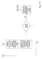
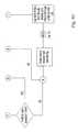
- FIGS. 7A-Cis a flowchart of a preferred initialization routine utilized by the controller of the adjustable pedal assembly of FIG. 1;
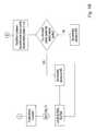
- FIGS. 8A-Cis a flowchart of a preferred main program loop utilized by the controller of the adjustable pedal assembly of FIG. 1;
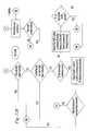
- FIGS. 9A-Bis a flowchart of a preferred memory button routine utilized by the controller of the adjustable pedal assembly of FIG. 1;
- FIGS. 10A-Bis a flowchart of a preferred find pedal hard stop routine utilized by the controller of the adjustable pedal assembly of FIG. 1;
- FIGS. 11A-Cis a flowchart of a preferred move pedal routine utilized by the controller of the adjustable pedal assembly of FIG. 1;
- FIGS. 12A-Bis a flowchart which is a continuation of the preferred move pedal routine of FIGS. 11A-C;
- FIGS. 13A-Bis a flowchart which is a continuation of the preferred move pedal routine of FIGS. 11A-C and 12 A-B.
- down or downwardrefers to a downward direction in the plane of the paper in FIGS. 2 and 3.
- fore or forwardrefers to a direction toward the front of the motor vehicle, that is, to the left in the plane of the paper in FIG. 2
- aft or rearwardrefers to a direction toward the rear of the motor vehicle, that is, to the right in the plane of the paper in FIG. 2 .
- FIG. 1shows an adjustable pedal assembly 10 for a motor vehicle, such as an automobile, according to a preferred embodiment of the present invention which has control pedals selectively adjustable to desired forward/rearward positions by an operator or driver of the motor vehicle. While the illustrated embodiments of the present invention are particularly adapted for use with an automobile, it is noted that the present invention can be utilized with any vehicle having at least one foot operated control pedal including trucks, buses, vans, recreational vehicles, earth moving equipment and the like, off road vehicles such as dune buggies and the like, air borne vehicles, and water borne vehicles.
- the illustrated adjustable pedal assembly 10includes first and second adjustable control pedals 12 a , 12 b and a control system 14 for selectively adjusting the position of the control pedals 12 a , 12 b .
- the control pedals 12 a , 12 bare adapted as brake and accelerator pedals respectively.
- the illustrated adjustable pedal assembly 10includes two control pedals 12 a , 12 b , it is noted that the adjustable pedal assembly 10 can have a single control pedal within the scope of the present invention such as, for example, a single control pedal adapted as a clutch, brake or accelerator pedal.
- the adjustable pedal assembly 10can have more than two control pedals 12 within the scope of the present invention such as, for example, three control pedals adapted as clutch, brake and accelerator pedals.
- the control pedals 12 a , 12 bare selectively adjustable by the motor vehicle operator in a forward/rearward direction as described in more detail hereinafter.
- the control pedals 10are preferably adjusted together simultaneously to maintain desired relationships between the control pedals such as, for example, “step over”, that is, the forward position of the accelerator pedal 12 b relative to the brake pedal, 12 a and “pedal angles”, that is, the orientation of the contact surfaces of the pedal pads. It is noted however, that individual adjustment of a single control pedal 12 a , 12 b is within the scope of the present invention.
- first control pedal 12 awhich is adapted as a brake pedal
- second control pedal 12 bwhich is adapted as an accelerator pedal
- suitable adjustable control pedals 12 a , 12 b adapted as both brake and accelerator pedalssee, for example, U.S. patent application Ser. No. 564,355, the disclosure of which is expressly incorporated herein in its entirety by reference.
- the first control pedal 12 aincludes an upper pedal arm or carrier 16 having first and second plates or members 18 , 20 , a lower pedal arm 22 supported by the upper pedal arm 16 and carrying a pad or pedal 24 for engagement by the foot of the motor vehicle operator, and a drive assembly 26 for moving of the lower pedal arm 22 relative to the upper pedal arm 16 to adjust the forward/rearward position of the pedal 24 .
- the upper pedal arm 16is sized and shaped for pivotal attachment to a mounting bracket 28 .
- the mounting bracket 28is adapted to rigidly attach the adjustable control pedal 12 to a firewall or other rigid structure of the motor vehicle in a known manner.
- the upper pedal arm 16is adapted for pivotal attachment to the mounting bracket 28 .
- the illustrated first and second members 18 , 20 of the upper pedal arm 16each have an opening 30 formed for cooperation with the mounting bracket 28 and an axle or pivot pin 32 .
- the upper pedal arm 16With the pivot pin 32 extending through the mounting bracket 28 and the openings 30 of the first and second members 18 , 20 , the upper pedal arm 16 is pivotable relative to the fixed mounting bracket 28 about a horizontally and laterally extending pivot axis 34 formed by the central axis of the pivot pin 32 .
- a spacer 36is preferably provided about the pivot pin 32 between the first and second members 18 , 20 to maintain a desired distance between the first and second members 18 , 20 .
- the illustrated first and second members 18 , 20 of the upper pedal arm 16are substantially identical and are rigidly connected together to pivot together about the pivot pin 32 in unison.
- the lower portion of the first and second members 18 , 20is adapted for supporting the lower pedal arm 22 and for selected fore and aft movement of the lower pedal arm 22 relative to the first and second members 18 , 20 along the lower portion as described in more detail hereinafter.
- the illustrated lower portionhas a pair of vertically spaced apart elongate openings or slots 38 , 40 formed therein which generally extend in a forward/rearward direction along the length of the lower portion.
- the illustrated slots 38 , 40are each substantially straight.
- the drive or lower slot 40is offset rearward of the guide or upper slot 38 but overlapping the upper slot 38 .
- the lower portionis substantially planar or flat at least in the areas adjacent the slots 38 , 40 and the slots 38 , 40 are open laterally through the entire thickness of the first and second members 18 , 20 .
- the slots 38 , 40are sized and shaped for cooperation with the lower pedal arm 22 for substantially linear forward/rearward movement of the pedal 24 relative the upper pedal arm 16 over a desired adjustment range, such as about three inches, as described in more detail hereinbelow. It is noted that the separate upper and lower slots 38 , 40 can alternatively be separate portions of a single slot such as a “C-shaped”, “S-shaped”, or other nonlinear slot.
- the upper pedal arm 16is operatively connected to a control device such as a clutch, brake or throttle such that pivotal movement of the upper pedal arm 16 about the pivot axis 34 operates the control device in a desired manner.
- the upper pedal arm 16can be connected to the control device by, for example, a push-pull or Bowden cable for mechanical actuation or by a sensor or electrical wire or cable for electronic actuation.
- the illustrated upper pedal arm 16is provided with a booster pin 42 for connection to the control device by a mechanical actuator.
- the illustrated upper pedal arm 16is also provided with a switch pin 44 for connection to a switch for indicator lights such as brake lights so that the indicator lights indicate actuation of the pedal, that is, pivotal movement about the pivot axis 34 , of the control pedal 12 by the operator.
- the upper and lower pedal arms 16 , 22are preferably formed of a suitable metal such as steel but one or both can alternatively be formed of other suitable materials such as, for example, plastics like NYLON, aluminum, or magnesium.
- the illustrated lower pedal arm 22is formed of an elongate plate oriented in a vertical plane substantially parallel to planes of the first and second members 18 , 20 .
- the upper end of the lower pedal arm 22is adapted for movement relative to the upper pedal arm 16 between first and second members 18 , 20 and along the upper and lower slots 38 , 40 .
- the upper end of the lower pedal arm 22is provided with upper and lower guide pins or blocks 48 , 50 laterally and horizontally extending therefrom to cooperate with the slots 38 , 40 of the first and second members 18 , 20 to form four sliding pin-and-slot connections for linearly moving the lower pedal arm 22 relative to the upper pedal arm 16 .
- the lower end of the lower pedal arm 22is sized and shaped to carry the rearward-facing pedal 24 .
- the pedal 24is adapted for depression by the driver of the motor vehicle to pivot the control pedal 12 about the pivot axis 34 to obtain a desired control input to the motor vehicle through the movement of the booster pin 42 .
- the pedal arm 22can be comprised of plastic or metal, and that the pedal arm 22 can be of unitary construction with the pedal or pad 24 or, alternatively, can have a pad support at its lower end to receive the pedal or pad 24 so that the pad 24 can be comprised of rubber or other suitable material for foot comfort.
- Bushings 52preferably encircle end portions of the guide pins 48 , 50 and extend within the slots 38 , 40 .
- the bushings 52are sized and shaped to closely conform with the guide pins 48 , 50 , particularly at the engagement surfaces contacting the edges of the slots 38 , 40 .
- the guide pins 48 , 50 and the bushings 52are sized and shaped so that there is very little or no vertical movement or “play” for the guide pins 48 , 50 within the slots 38 , 48 .
- Flanges of the bushings 52are preferably sized to extend between the lower pedal arm 22 and the first and second members 18 , 20 so that there is very little or no lateral movement or “play” for the lower pedal arm 22 between the first and second members 18 , 20 .
- the bushings 52are preferably formed of a suitable plastic or polymer material but can alternatively be any other type of suitable wear resistant and/or low friction material.
- the drive assembly 26includes a screw shaft or drive screw 54 , a drive screw attachment or housing 56 for securing the drive screw 54 to the upper pedal arm 16 , a drive nut 58 adapted for movement along the drive screw 54 in response to rotation of the drive screw 54 , an electric motor 60 for rotating the drive screw 54 , and a drive cable 62 for operatively connecting the electric motor 60 to the drive screw 54 and transmitting rotational motion and torque thereto.
- the drive screw 54is an elongate shaft having a threaded portion adapted for cooperation with the drive nut 58 .
- the drive screw 54is preferably formed of metal such as, for example, steel but can be alternately formed of a plastic resin such as, for example, NYLON.
- the forward end of the drive screw 54is journaled by the drive screw housing 56 for rotation of the drive screw 54 about its longitudinal axis by the electric motor 60 .
- the drive screw 54rearwardly extends from the drive screw housing 56 generally parallel to and adjacent the lower slots 38 in the first and second members 18 , 20 in a cantilevered fashion. Mounted in this manner, the drive screw 54 is generally horizontal.
- the illustrated drive screw 54is provided with a bushing 64 for connection to the housing 56 to form a relatively fixed rotating joint.
- the drive screw 56can alternatively be connected to the drive screw housing 56 with a self-aligning or freely pivoting rotating joint, that is, a joint which freely permits pivoting of the drive screw 54 relative to the drive screw housing 56 and the first and second members 18 , 20 about at least axes perpendicular to the drive screw rotational axis 66 .
- the self-aligning jointautomatically corrects misalignment of the drive screw 54 and/or the drive nut 58 .
- the self-aligning jointalso allows the lower slot 40 to be nonlinear when desired.
- the self aligning jointcan be, for example, a ball/socket type joint.
- the drive screw housing 56is sized and shaped for supporting the forward end of the drive screw 54 and attaching the drive screw 54 to the first and second members 18 , 20 .
- the drive screw housing 56is preferably molded of a suitable plastic material such as, for example, NYLON but can alternatively be formed of metal such as steel.
- the illustrated drive-screw housing 56is secured to the upper pedal arm 16 with a snap-fit connection. It is noted, however, that the drive screw housing 56 can be secured to the upper pedal arm 16 in other suitable manners such as, for example, welding, staking, or mechanical fasteners.
- the drive nut 58is adapted for axial movement along the drive screw 54 in response to rotation of the drive screw 54 .
- the drive nut 58is preferably molded of a suitable plastic material such as, for example, NYLON but can alternatively be formed of metal such as, for example steel.
- the illustrated drive nut 58is rigidly secured to the lower guide pin 50 .
- the lower guide pin 50can be alternatively connected to the drive nut 58 with a self-aligning or freely pivoting joint, that is, a joint which freely permits pivoting of the drive nut 58 relative to the lower guide pin 50 about at least axes perpendicular to the rotational axis 66 of the drive screw 54 .
- the self-aligning jointautomatically corrects misalignment of the drive nut 58 and/or the drive screw 54 .
- the self aligning jointcan be, for example, a ball/socket type joint.
- the electric motor 60can be of any suitable type and can be secured to the firewall or other suitable location such as, for example, the mounting bracket 28 .
- the drive cable 62is preferably a flexible push-pull-type or Bowden cable and connects the output shaft of the electric motor 60 and the forward end of the drive screw 54 so that rotation of the electric motor 60 rotates the drive screw 54 .
- the drive screw 54 and the electric motor 60can be alternatively connected with a rigid connection.
- suitable gearing 68is provided between the electric motor 60 and the drive screw 54 as necessary depending on the requirements of the adjustable pedal assembly 10 .
- the fixed portion or sheath of the drive cable 62is rigidly secured to the forward end of the drive screw housing 56 and a rotating portion or core of the drive cable 62 is operatively connected to the forward end of the drive screw 54 to rotate the drive screw 54 therewith.
- U.S. patent application Ser. No. 09/492,2308the disclosure of which is expressly incorporated herein in its entirety by reference, for a more detailed description of a suitable drive screw, housing, and/or cable support.
- U.S. patent application Ser. No. 09/642,975the disclosure of which is expressly incorporated herein in its entirety by reference, for a more detailed description of the control pedal 12 .
- the control system 14preferably includes a central processing unit (CPU) or controller 70 for operating the electric motor 60 , an operator interface 72 for exchanging information between the driver and the controller 70 , and at least one sensor 74 for detecting motion of the control pedals 12 a , 12 b and providing such motion information to the controller 70 .
- the control system 14forms a control loop wherein the controller 70 selectively activates and deactivates the electric motor 60 . When activated, the electric motor 60 rotates the drive screws 54 through the drive cables 62 . It is noted that while the drive screws 54 of the illustrated embodiment are connected to the electric motor 60 in parallel, they can alternatively be connected to the electric motor 60 in series.
- the sensor or sensors 74detect movement of the control pedals 12 a , 12 b and send(s) signals to the controller 70 which enables the controller 70 to deactivate the electric motor 60 when movement to a desired position has been obtained.
- the controller 70includes processing means and memory means which are adapted to control operation of the adjustable pedal assembly 10 as described in detail herein.
- the controller 70is preferably in communication with a motor vehicle control unit 76 through a local bus 78 of the motor vehicle or a direct connection so that motor vehicle information, such as ignition switch information, can be supplied to or examined by the controller 70 and status of the adjustable pedal assembly 10 can be supplied to or examined by the motor vehicle control unit 76 .
- motor vehicle informationsuch as ignition switch information
- the controllercan alternatively be the motor vehicle control unit 76 or a controller of another system of the motor vehicle such as, for example, a keyless entry system or a powered seat system.
- the illustrated operator interface 72includes a forward button or switch 80 , a reverse or rearward button or switch 82 , an indicator device 84 , and first and second memory buttons or switches 86 , 88 .
- the forward switch 80sends control signals to the controller 70 to move the control pedals 12 a , 12 b in a forward direction.
- the reverse switch 82sends control signals to the controller 70 to move the control pedals 12 a , 12 b in a rearward direction.
- the illustrated forward and rearward switches 80 , 82are a single rocker-type switch but can be other types of suitable switches such as, for example, push-button switches or toggle switches.
- the illustrated indicator device 84is an indicator or status light such as an LED which is selectively illuminated to convey information to the operator. It is noted that the indicator device 84 can alternatively be other suitable types of devices which can convey information such as, for example, an LED or LCD display.
- the memory switches 86 , 88send control signals to the controller 70 to move the control pedals 12 a , 12 b to preferred locations previously saved in memory of the controller 70 .
- the controller 70saves the current position in memory so that subsequent actuation of that memory switch 86 , 88 will send a control signal to the controller 70 to move the control pedals 12 a , 12 b to the current location.
- the indicator device 84acknowledges the saving of the current position by for example, blinking the indicator light for a predetermined period of time.
- the illustrated memory switches 86 , 88are a single push-button switches but can be other types of suitable switches such as, for example, toggle switches.
- the operator interface 72can also include other control switches when desired such as, for example, a lock out button or switch which when activated sends control signals to deactivate the system and prevent movement of the control pedals 12 a , 12 b and/or an override button or switch which when activated permits the control pedals 12 a , 12 b to be moved by the driver in a desired manner regardless of existing conditions.
- each control pedal 12 a , 12 bwith a sensor 74 to detect movement of the control pedals 12 a , 12 b and send signals relating to such movement information to the controller 70 .
- a single sensor 74 or more than two sensors 74can be utilized.
- the illustrated sensors 74are located adjacent the drive screws 54 and are adapted provide movement information, in the form of distance and speed information, to the controller 70 .
- the sensors 74are preferably hall-effect switches mounted adjacent ring magnets 90 .
- each ring magnet 90comprises a predetermined number of north and south poles such as, for example, a total of about 24 to 34 north and south poles.
- a ring magnet with any number of polescan be used.
- the ring magnet 90is mounted for rotation with the drive screw 54 so that the predetermined number of magnet poles pass the sensor 74 each revolution of the drive screw 54 .
- the sensor 74provides a square wave pulse stream to the controller 70 .
- the width of each pulseindicates the time one type of magnet pole was adjacent the sensor 74 and the width between pulses indicates the time the other type of magnet pole was adjacent the sensor. Therefore, width of the pulses and width between pulses proportionally decreases as rotational velocity of the drive screw 54 increases.
- Speedcan be determined by pulse width, width between pulses, or preferably by both pulse width and width between pulses.
- the distance the drive nut 58 , and thus the lower pedal arm 22 , travels with each rotation of the drive screw 54is preprogrammed in the controller 70 . Therefore, the controller 70 can determine both the location and speed of the lower pedal arms 22 from the movement information received from the sensors 74 . This motion information is used by the controller 70 in many ways as described in detail hereinbelow.
- the sensors 74can alternatively be position sensors such as, for example, a linear hall-effect sensor and/or a linear potentiometer.
- the sensors 74can also alternatively be a current shunt on the electric motor 60 providing motor commutator pulses to detect position or motor current. Therefore, it is noted that the sensors 74 can alternatively have other locations such as, for example, between the upper and lower pedal arms 16 , 22 and/or at the electric motor 60 .
- Other motion information sensors 74 and locations for the sensors 74will be apparent to those skilled in the art given the benefit of this disclosure.
- the motion information from the sensors 74can be utilized to automatically stop the control pedals 12 a , 12 b at ends of travel along the drive screw 54 .
- the controller 70is preferably adapted to stop the motor 60 when motion information indicates that the drive nut 58 has reached a predetermined end of travel along the drive screw 54 prior to engaging a “hard” or mechanical stop or abutment.
- the position of the “soft” or electronic stop points relative to the hard stop points at the end of travelare preferably preprogrammed or determined by the controller 70 .
- the controller 70determines that the control pedals 12 a , 12 b have reached the soft or electronic stop points, the controller 70 stops the motor 60 and thus movement of the drive nuts 58 along the drive screws 54 .
- Fore-aft movement of the lower pedal arms 16is electronically stopped without engaging mechanical stops and resulting stress on the motor 60 and mechanical components.
- a hard stopis engaged, the motor 60 stalls and current increases which may cause overheating of the motor 60 and a resulting shortened life of the motor 60 .
- the adjustable pedal assembly 10is preferably provided with hard stops for limiting travel of the drive nuts 58 beyond the soft stops for use in initializing or resetting the system 14 an use in the event of a failure of the soft stops.
- the hard stopsinclude the ends of the upper and lower slot 38 , 40 which form abutments which are engaged by the upper and lower guide pins 48 , 50 at the end of travel along the slots 38 , 40 to limit fore-aft movement of the lower arms 16 and axial movement of the drive nuts 58 .
- the motion information from the sensors 74can be utilized by the controller 70 to move the control pedals 12 a , 12 b to desired positions. Because each pulse of the sensor output indicates a predetermined distance traveled, the total number of pulses indicates the total distance traveled. Therefore, by setting a home position at zero pulses, every other position along the travel length can be defined by a number of pulses from the home position. The current position therefore can be identified by the controller 70 which keeps track of the cumulative effect of all of the pulses which have occurred since traveling from the home position. In the illustrated embodiment, the home or forward soft stop is set as zero pulses and the travel or rearward soft stop is set as the total number of pulses from the home soft stop. In this manner, the current position can be stored by storing the number of pulses that the current position is away from the home position.
- the motion information from the sensors 74can be utilized to detect an obstruction in the path of at least one of the control pedals 12 a , 12 b such as, for example, the operator's foot.
- a potential “pinch” situationis detected if signals from the sensors 74 to the controller 70 indicate that there is a stall condition, by change in speed, acceleration or the like, which indicates that an obstruction has been engaged by at least one of the control pedals 12 a , 12 b .
- the controller 70automatically stops the motor 60 and/or reverses direction of the movement for a predetermined distance or to the previous position to prevent injury to a person or damage to an object or the adjustable pedal assembly 10 .
- the controller 70places the system in fault mode.
- the indicator device 84identifies that the system 14 is in fault mode such as, for example, by blinking the indicator light.
- each pulse widthis a function of time (the width is the time to travel a predetermined distance)
- the pulse widths or velocity informationcan be utilized to detect a stalled or obstruction condition.
- a time or pulse widthis stored indicating a full speed pulse.
- the full speed pulseis determined each motion cycle to reduce the effect of long term degradations.
- each pulse widthis compared to the stored full speed pulse width to determine if a stalled condition is beginning to take place.
- an averaging algorithmis utilized wherein each pulse width (or some derivative of each pulse width) is compared to the sum of the stored full speed pulse width and a constant value.
- the constant valuecan be a fixed percentage, such as 50%, of the saved full speed pulse width.
- the fixed percentageis dependant on variables of the mechanical system and can be from about 10% to about 300%. Accordingly, each system must be tested to determine the optimum fixed percentage. If a measured pulse width is greater than the sum of the stored full speed pulse width and the constant value, there is an indication of a stall condition arising. Typically, more than one pulse width should indicate a stall condition arising before acting on the stalled condition depending on the desired sensitivity of the system 14 .
- the motion information from the sensors 74can be utilized to return the control pedals 12 a , 12 b to a stored preferred location (a stored number of pulses from the home position) when selected by the driver.
- the driveradjusts the control pedals 12 a , 12 b to a preferred location and engages one of the memory switches 86 , 88 for a predetermined period of time which is preferably verified by the indicator device 84 , such as by a flash of the indicator light, so that the preferred location is saved in memory.
- the controller 70automatically activates the motor 60 to rotate the drive screws 54 and move the control pedals 12 a , 12 b from the current position (a known number of pulses from the home position) to the saved position (a stored number of pulses from the home position).
- the controller 70automatically stops the motor 60 when the motion information from the sensors 74 that the necessary number of pulses, in the necessary direction, have occurred to reach the stored position.
- Each control pedal 12 a , 12 bpreferably includes a separate sensor 74 so that motion information is obtained regarding each of the drive screws 54 .
- the controller 70can identify when the control pedals 12 a , 12 b , are not moving in the same manner, that is maintaining the same relationship to each other.
- the controller 70deactivates the motor 60 if there is an indication that a predetermined relationship between two or more of the control pedals 12 a , 12 b is not maintained.
- the predetermined relationshipcan be the step over of the brake and accelerator pedals.
- the controller 70places the system in fault mode.
- the indicator device 84identifies that the system 14 is in fault mode such as, for example, by blinking the indicator light.
- the controller 70is preferably adapted to selectively trigger an initialization process to identify where the control pedals 12 a , 12 b are located. This initialization process can be utilized at start up after any loss of power, such as a battery change, and/or after a system shut down due to failure detection or fault mode.
- the controller 70activates the motor 60 to move the drive nuts 58 forward until they reach the forward or home hard stop.
- the controller 70then reverses the motor 60 to move the drive nuts 58 in a rearward direction until they reach the rearward or travel hard stop.
- the controller 70compares the distance between the located hard stops, or alternatively the determined soft stops, to determine if an artificial hard stop or obstruction was engaged.
- the controller 70sets the soft stops a predetermined distance from the located hard stops. If the distance is not adequate, that is it indicates an obstruction was engaged, the controller 70 places the system in fault mode.
- the indicator device 84identifies that the system 14 is in fault mode such as, for example, blinking the indicator light.
- the LEDcan blink at different rates depending on the type of failure such as, for example, a one second rate for a step over failure, a two second rate for an initialization failure, a 0.25 second rate for a temporary fault in the circuit such as an H-bridge.
- meansare provided for resetting or initializing the system 14 when in fault mode such as, for example, a reset switch.
- the reset or initialization processis triggered by engaging the forward switch 80 and each of the memory switches 86 , 88 simultaneously.
- FIGS. 7A-13Billustrate flow charts for preferred operation of the controller 70 .
- the initialization program loop or routineis best shown in FIGS. 7A-C.
- the controller 70runs a “find pedal hard stops routine” when the initialization process is triggered.
- the find pedal hard stops routineis described in more detail hereinbelow with regard to FIG. 10 . If the hard stops are not found, the system 14 is placed in fault mode and the LED light 84 is blinked at a predetermined rate such as two seconds on and two seconds off. If the hard stops are found, the soft stops are then determined by the controller 70 . Preferably, the home soft stop location is determined by adding a predetermined distance (predetermined number of pulses) from the home hard stop.
- the travel soft stopis determined by subtracting the home soft stop location (number of pulses from the home hard stop) from the from the travel hard stop location (number of pulses from the home hard stop). The distance between the travel and home soft spots is compared to a predetermined distance to determine if an artificial hard stop or obstacle was engaged. If an obstacle was engaged, the system 14 is placed in fault mode and the LED light 84 is blinked at a predetermined rate such as two seconds on and two seconds off. If an obstacle was not engaged, stored memory positions for the memory switches 86 , 88 are set to the home soft stop and the control pedals 12 a , 12 b are moved between the travel soft stop and the home soft stop.
- the system 14is placed in fault mode and the LED light 84 is blinked at a predetermined rate, such as two seconds on and two seconds off. If a stall or obstruction is not detected during this movement, the two pedal positions are set equal and the main program loop is initiated.
- the main program loopis best shown in FIGS. 8A-C.
- the controller 70checks for a step over fault condition (the two control pedals are no longer at equal positions). If a step over fault condition is determined, the system 14 is placed in fault and the LED light 84 is blinked at a predetermined rate such as one second on and one second off. If the user attempts to reset the system 14 , the initialization process of FIGS. 7A-C is initiated. If a step over fault condition is not detected, the controller 70 checks for an H-bridge or circuit fault condition.
- the system 14is placed in fault and the LED light 84 is blinked at a predetermined rate such as a quarter of a second on and a quarter of a second off.
- the controller 70continues to check if the condition remains and clears the fault state when the condition no longer exists. If a circuit fault condition is not detected and the forward switch 80 or the rearward switch 82 is pressed for at least a predetermined period of time, such as more than ten milliseconds, the move pedal routine (FIGS. 11A-C) is initiated after properly setting the direction to forward or rearward depending on which direction switch 80 , 82 was pressed.
- the memory button routine(FIGS. 9A-B) is initiated after properly setting the button number to 1 or 2 depending on which memory switch 86 , 88 was pressed. After completing the memory routine, the move pedal routine is initiated.
- the memory button program loop or routineis best shown in FIGS. 9A-B. If the memory switch 86 , 88 is released prior to a predetermined period of time, such as two seconds, memory movement is enabled. The controller 70 determines the difference between the current pedal position and the desired memory position (number of pulses). If the current pedal position is greater than the memory position, the movement direction is set to forward and the move pedal routine is initiated. If the current pedal position is less than the memory position, the movement direction is set to rearward and the move pedal routine is initiated.
- the current pedal position(number of pulses from the home position) is saved into the memory position of the memory switch 86 , 88 that was pressed by the operator and the LED 84 is blinked for a predetermined period of time such as 250 milliseconds.
- the find pedal hard stop program loop or routineis best shown in FIGS. 10A-B.
- the movement set pointthat is the current position, is set to zero and the movement direction is set to forward.
- the move pedal routineis initiated to move the control pedals 12 a , 12 b in the forward direction for a number of pulses which ensures that the forward hard stop will be engaged.
- the two pedal positionsare set to zero because they are at the home hard stop.
- the movement directionis set to rearward and the move pedal routine is initiated to move the control pedals 12 a , 12 b in the rearward direction for a number of pulses which ensures that the rearward hard stop will be engaged.
- the travel hard stopis set and the controller 70 returns to the initialization routine.
- the move pedal program loop or routineis best shown in FIGS. 11A-13B. Initially, previous and saved pulse width counts are set to zero.
- the hall-effect sensor 74 of the first control pedal 12 ais monitored to determine the state of the sensor pulses (high or low). Each time there is a transition in output from the sensor 74 , from either low to high or high to low, the pulse count indicating the current position of the first pedal 12 a is incremented or decremented depending on the direction of travel.
- the hall-effect sensor 74 of the second control pedal 12 bis monitored in the same manner.
- the controller 70can determine whether the pulse count indicating the current position is equal to the set point indicating a desired position. When a set point is reached, the movement is complete.
- the controller 70continuously checks for various conditions which indicate movement should be stopped. For example, the controller 70 determines if the home soft stop has been reached if travelling in the forward direction and if the travel soft stop has been reached in travelling in the rearward direction. If a soft stop is reached, movement is complete. The controller 70 also determines if a stall condition is present. If a stall condition is detected, movement is stopped and/or reversed. The controller 70 further determines if there is a step over error, that is the first and second control pedals 12 a , 12 b are not in the same current position. If there is a step-over error, movement is complete. The move routine continues to loop until the movement is complete or the direction switch 80 , 82 is released by the operator and the controller stops the motor 60 .
- rotation of the motor 60rotates the drive screw 54 through the drive cable 62 and causes the drive nut 58 to axially move along the drive screw 54 in the desired direction.
- the drive nut 58moves along the drive screw 54 because the drive nut 58 is held against rotation with the drive screw 54 by the lower guide pin 50 .
- the lower guide pin 50moves along the lower slots 40 because the lower guide pin 50 is secured to the drive nut 58 .
- the pedal 24travels in a substantially linear and horizontal path, that is, the pedal 24 moves in a forward/rearward direction and generally remains at the same height relative to the fixed mounting bracket 28 and the upper pedal arm 16 which does not move relative the mounting bracket 28 during adjustment of the pedal 24 .
- the lower pedal arm 22pivots as it moves so that the orientation of the pedal 24 slightly changes. This change in orientation of the pedal 24 is typically too small to be detected by the motor vehicle operator.
- the upper pedal arm 16remains in fixed position relative to the mounting bracket 28 .
- activation of the motor 60changes the position of the lower pedal arm 22 relative to the upper pedal arm 16 and the position of the pedal 24 relative to the motor vehicle operator but not the position of the upper pedal arm 16 relative to the mounting bracket 28 and therefore does not affect the connection of the upper pedal arm 16 to the control device of the motor vehicle through the booster pin 42 .
Landscapes
- Engineering & Computer Science (AREA)
- Transportation (AREA)
- Mechanical Engineering (AREA)
- Chemical & Material Sciences (AREA)
- Combustion & Propulsion (AREA)
- Physics & Mathematics (AREA)
- General Physics & Mathematics (AREA)
- Automation & Control Theory (AREA)
- Mechanical Control Devices (AREA)
- Auxiliary Drives, Propulsion Controls, And Safety Devices (AREA)
- Braking Elements And Transmission Devices (AREA)
Abstract
Description
Claims (12)
Priority Applications (3)
| Application Number | Priority Date | Filing Date | Title |
|---|---|---|---|
| US09/748,666US6739212B2 (en) | 2000-12-22 | 2000-12-22 | Adjustable pedal controller with obstruction detection |
| EP01650152AEP1217493A1 (en) | 2000-12-22 | 2001-12-18 | Adjustable pedal controller with obstruction detection |
| US10/759,994US7219575B2 (en) | 2000-12-22 | 2004-01-16 | Adjustable pedal controller with obstruction detection |
Applications Claiming Priority (1)
| Application Number | Priority Date | Filing Date | Title |
|---|---|---|---|
| US09/748,666US6739212B2 (en) | 2000-12-22 | 2000-12-22 | Adjustable pedal controller with obstruction detection |
Related Child Applications (1)
| Application Number | Title | Priority Date | Filing Date |
|---|---|---|---|
| US10/759,994Continuation-In-PartUS7219575B2 (en) | 2000-12-22 | 2004-01-16 | Adjustable pedal controller with obstruction detection |
Publications (2)
| Publication Number | Publication Date |
|---|---|
| US20020078782A1 US20020078782A1 (en) | 2002-06-27 |
| US6739212B2true US6739212B2 (en) | 2004-05-25 |
Family
ID=25010414
Family Applications (2)
| Application Number | Title | Priority Date | Filing Date |
|---|---|---|---|
| US09/748,666Expired - Fee RelatedUS6739212B2 (en) | 2000-12-22 | 2000-12-22 | Adjustable pedal controller with obstruction detection |
| US10/759,994Expired - Fee RelatedUS7219575B2 (en) | 2000-12-22 | 2004-01-16 | Adjustable pedal controller with obstruction detection |
Family Applications After (1)
| Application Number | Title | Priority Date | Filing Date |
|---|---|---|---|
| US10/759,994Expired - Fee RelatedUS7219575B2 (en) | 2000-12-22 | 2004-01-16 | Adjustable pedal controller with obstruction detection |
Country Status (2)
| Country | Link |
|---|---|
| US (2) | US6739212B2 (en) |
| EP (1) | EP1217493A1 (en) |
Cited By (12)
| Publication number | Priority date | Publication date | Assignee | Title |
|---|---|---|---|---|
| US20040200308A1 (en)* | 2000-12-22 | 2004-10-14 | Flynn Charles Lee | Adjustable pedal controller with obstruction detection |
| US20040244527A1 (en)* | 2003-06-09 | 2004-12-09 | Christopher Rixon | Direct drive adjustable pedal system with step-over control |
| US20050187688A1 (en)* | 2001-12-27 | 2005-08-25 | Lear Corporation | Method of detecting obstructions caused by motor-driven power windows and similar devices using fuzzy logic algorithms |
| US20060169092A1 (en)* | 2002-11-22 | 2006-08-03 | Jaume Prat Terradas | Adjustable pedal |
| US20070276582A1 (en)* | 2006-05-25 | 2007-11-29 | Bill Coughlin | Haptic apparatus and coaching method for improving vehicle fuel economy |
| US20080272765A1 (en)* | 2007-05-03 | 2008-11-06 | Agency For Defense Development | Brushless DC Motor Using Linear Hall-Effect Sensor And Realization Method Of Speed Signal Thereof |
| US20090025505A1 (en)* | 2007-07-24 | 2009-01-29 | Jason Allen Booher | Adjustable pedal system with ratio modifier |
| US20090043467A1 (en)* | 2007-08-09 | 2009-02-12 | Ford Global Technologies, Llc | Driver Advisory System for Fuel Economy Improvement of a Hybrid Electric Vehicle |
| US20090090061A1 (en)* | 2005-12-12 | 2009-04-09 | Jochen Held | Control system for controlling an adjusting device operated by electric motor in a motor vehicle |
| US20090112439A1 (en)* | 2007-10-30 | 2009-04-30 | Ford Global Technologies, Llc | System and method for obtaining an adjustable accelerator pedal response in a vehicle powertrain |
| US20100107804A1 (en)* | 2008-11-04 | 2010-05-06 | Tervol Stuart A | Fixed pedal assembly with multi-piece support bracket and captive pivot |
| US11009903B1 (en)* | 2020-02-12 | 2021-05-18 | Hyundai Motor Company | Foldable brake pedal apparatus for autonomous vehicle |
Families Citing this family (20)
| Publication number | Priority date | Publication date | Assignee | Title |
|---|---|---|---|---|
| US6293077B1 (en)* | 2000-05-02 | 2001-09-25 | Mtd Products Inc | Deck attachment and lift system |
| US6330838B1 (en)* | 2000-05-11 | 2001-12-18 | Teleflex Incorporated | Pedal assembly with non-contact pedal position sensor for generating a control signal |
| US6571660B2 (en)* | 2001-04-17 | 2003-06-03 | Delphi Technologies, Inc. | Adjustable pedal assembly |
| US6595082B2 (en)* | 2001-07-03 | 2003-07-22 | Delphi Technologies, Inc. | Adjustable pedal system with fail-safe device |
| US7191680B2 (en) | 2002-01-01 | 2007-03-20 | Drivesol Worldwide, Inc. | Stepping motor direct drive adjustable pedal assembly |
| US20030121354A1 (en) | 2002-01-01 | 2003-07-03 | Christopher Rixon | Stepping motor direct drive adjustable pedal assembly |
| EP1385077A1 (en)* | 2002-07-26 | 2004-01-28 | Dura Global Technologies, Inc. | Plastic adjustable accelerator pedal with internal drive mechanism |
| US7270028B2 (en) | 2004-02-03 | 2007-09-18 | Drivesol Worldwide, Inc. | Adjustable pedal assembly with step-over control |
| JP4401926B2 (en) | 2004-10-14 | 2010-01-20 | ヤマハ発動機株式会社 | Relative position detection control device and saddle riding type vehicle |
| JP4911889B2 (en)* | 2004-10-14 | 2012-04-04 | ヤマハ発動機株式会社 | Relative position detection device and saddle riding type vehicle |
| JP2006112879A (en)* | 2004-10-14 | 2006-04-27 | Yamaha Motor Co Ltd | Relative position detector and saddle ride type vehicle |
| MXPA06011291A (en)* | 2005-09-30 | 2007-06-08 | 9141 0720 Quebec Inc | Motorized closure operating device with electronic control system. |
| FR2930056A1 (en)* | 2008-04-15 | 2009-10-16 | Coutier Moulage Gen Ind | Pedal assembly for motor vehicle, has brake and accelerator pedals pivotably mounted around median axis and respectively situated at left and right sides of axis, where axis is oriented in inclined manner with reference to mounting position |
| CN102795107B (en)* | 2012-08-27 | 2015-08-26 | 珠海英搏尔电气有限公司 | Electronic throttle assembly |
| CN105083004A (en)* | 2014-05-06 | 2015-11-25 | 上海通用汽车有限公司 | Magneto-electric electronic throttle pedal assembly |
| CN104827901A (en)* | 2014-08-19 | 2015-08-12 | 北汽福田汽车股份有限公司 | Motor vehicle pedal and method for adjusting the same |
| US9454904B1 (en)* | 2015-03-16 | 2016-09-27 | Ford Global Technologies, Llc | Safety pedal obstruction and command intention detection |
| TWI663086B (en)* | 2018-06-20 | 2019-06-21 | 宏碁股份有限公司 | Braking system for autonomous car and setting method thereof |
| US20230406098A1 (en)* | 2022-06-20 | 2023-12-21 | Ford Global Technologies, Llc | Methods and apparatus for determining positions of a stowable pedal assembly |
| CN114954249A (en)* | 2022-06-29 | 2022-08-30 | 长城汽车股份有限公司 | Pedal control method and device, storage medium and vehicle |
Citations (47)
| Publication number | Priority date | Publication date | Assignee | Title |
|---|---|---|---|---|
| US3319487A (en) | 1964-01-09 | 1967-05-16 | Gen Motors Corp | Vehicle control pedals |
| US3511109A (en) | 1968-10-14 | 1970-05-12 | Gen Motors Corp | Adjustable control pedals |
| US3643525A (en) | 1970-05-26 | 1972-02-22 | Gen Motors Corp | Adjustable control pedals for vehicles |
| US3643524A (en) | 1970-05-26 | 1972-02-22 | Gen Motors Corp | Control pedals for vehicles |
| US3975972A (en) | 1975-04-16 | 1976-08-24 | Muhleck Earl M | Adjustable pedal construction |
| US4470570A (en) | 1982-09-29 | 1984-09-11 | The Boeing Company | Control assembly for aircraft |
| US4497399A (en) | 1982-12-03 | 1985-02-05 | General Motors Corporation | Adjusting mechanism for a manually operated clutch |
| US4683977A (en) | 1985-05-15 | 1987-08-04 | Thomas Murphy | Adjustable pedal assembly |
| US4779481A (en) | 1987-04-16 | 1988-10-25 | J. I. Case Company | Adjustable two-pedal swing control apparatus |
| US4870871A (en) | 1987-05-22 | 1989-10-03 | Wickes Manufacturing Company | Adjustable accelerator and brake pedal mechanism |
| US4875385A (en) | 1986-08-18 | 1989-10-24 | Sitrin Gabriel M | Control pedal apparatus for a motor vehicle |
| US4989474A (en) | 1986-08-18 | 1991-02-05 | Brecom Corporation | Control pedal apparatus for a motor vehicle |
| US5010782A (en) | 1988-07-28 | 1991-04-30 | Fuji Kiko Company, Ltd. | Position adjustable pedal assembly |
| US5056742A (en) | 1987-11-13 | 1991-10-15 | The Boeing Company | Modular rudder pedal and brake control assembly for aircraft |
| US5078024A (en) | 1986-08-18 | 1992-01-07 | Comfort Pedals Inc. | Control pedal apparatus for a motor vehicle |
| US5086663A (en) | 1989-07-28 | 1992-02-11 | Fuji Kiko Company, Limited | Adjustable pedal |
| US5351573A (en) | 1991-10-07 | 1994-10-04 | Cicotte Edmond B | Adjustable automobile pedal system |
| US5460061A (en) | 1993-09-17 | 1995-10-24 | Comfort Pedals, Inc. | Adjustable control pedal apparatus |
| US5497326A (en)* | 1994-08-03 | 1996-03-05 | The Cherry Corporation | Intelligent commutation pulse detection system to control electric D.C. motors used with automobile accessories |
| US5632183A (en) | 1995-08-09 | 1997-05-27 | Comfort Pedals, Inc. | Adjustable pedal assembly |
| US5697260A (en) | 1995-08-09 | 1997-12-16 | Teleflex Incorporated | Electronic adjustable pedal assembly |
| US5722302A (en) | 1995-08-09 | 1998-03-03 | Teleflex, Inc. | Adjustable pedal assembly |
| US5771752A (en) | 1991-10-07 | 1998-06-30 | Cicotte; Edmond B. | Adjustable automobile pedal system |
| US5819593A (en) | 1995-08-09 | 1998-10-13 | Comcorp Technologies, Inc. | Electronic adjustable pedal assembly |
| US5855143A (en) | 1997-11-25 | 1999-01-05 | Ford Global Technologies, Inc. | Adjustable pedal apparatus |
| US5861745A (en)* | 1995-09-29 | 1999-01-19 | Robert Bosch Gmbh | Measuring device for contactless determination of relative angular position with an improved linear range |
| US5884532A (en) | 1997-04-28 | 1999-03-23 | Tecnology Holding Company Ii | Adjustable pedal apparatus |
| US5901614A (en) | 1997-11-25 | 1999-05-11 | Ford Global Technologies, Inc. | Adjustable clutch pedal system |
| US5913946A (en) | 1997-11-25 | 1999-06-22 | Ford Global Technologies, Inc. | Adjustable accelerator pedal apparatus |
| US5927154A (en) | 1998-02-11 | 1999-07-27 | General Motors Corporation | Adjustable brake and clutch pedals |
| US5952801A (en) | 1992-04-22 | 1999-09-14 | Nartron Corporation | Power window or panel controller |
| US5994858A (en) | 1997-09-01 | 1999-11-30 | Alps Electric Co., Ltd. | Method and apparatus for detecting obstruction to powered window movement |
| US5996438A (en) | 1998-06-23 | 1999-12-07 | General Motors Corporation | Adjustable accelerator pedal |
| US6019015A (en) | 1998-02-11 | 2000-02-01 | General Motors Corporation | Adjustable accelerator pedal |
| US6051945A (en) | 1999-01-25 | 2000-04-18 | Honda Giken Kogyo Kabushiki Kaisha | Anti-pinch safety system for vehicle closure device |
| US6064165A (en) | 1992-04-22 | 2000-05-16 | Nartron Corporation | Power window or panel controller |
| US6070489A (en) | 1998-10-26 | 2000-06-06 | Teleflex Incorporated | Mounting assembly for an adjustable pedal |
| US6109241A (en) | 1999-01-26 | 2000-08-29 | Teleflex Incorporated | Adjustable pedal assembly with electronic throttle control |
| US6114820A (en) | 1998-03-13 | 2000-09-05 | Koito Manufacturing Co., Ltd. | Power window apparatus having safety unit |
| US6125583A (en) | 1997-08-13 | 2000-10-03 | Atoma International Inc. | Power sliding mini-van door |
| US6134492A (en) | 1995-06-07 | 2000-10-17 | Automotive Technologies International Inc. | Apparatus and method for adjusting pedals in a vehicle |
| US6151984A (en) | 1997-11-21 | 2000-11-28 | Teleflex Incorporated | Adjustable pedal assembly |
| US6151985A (en) | 1999-04-01 | 2000-11-28 | Daimlerchrysler Corporation | Adjustable pedal apparatus |
| US6151986A (en) | 1997-10-09 | 2000-11-28 | Ksr Industrial Corporation | Adjustable vehicle control pedals |
| US6247381B1 (en)* | 2000-01-27 | 2001-06-19 | Dura Global Technologies, Inc. | Adjustable brake, clutch and accelerator pedals |
| US6289761B1 (en)* | 2000-02-04 | 2001-09-18 | Dura Global Technologies, Inc. | Automatic adjustable brake, clutch and accelerator pedals |
| US6316897B1 (en)* | 2000-07-18 | 2001-11-13 | Ford Global Tech., Inc. | System for controlling adjustable pedals |
Family Cites Families (7)
| Publication number | Priority date | Publication date | Assignee | Title |
|---|---|---|---|---|
| US5263488A (en)* | 1992-10-05 | 1993-11-23 | Nicolet Instrument Corporation | Method and apparatus for localization of intracerebral sources of electrical activity |
| FR2739947B1 (en)* | 1995-10-17 | 1997-12-12 | Renault | MOTOR VEHICLE CRANKSET HAVING A DEVICE FOR ADJUSTING THE HEIGHT AND THE ORIENTATION OF THE PEDALS |
| US6766713B2 (en)* | 2000-01-27 | 2004-07-27 | Dura Global Technologies, Inc. | Control system for adjustable pedal assembly having individual motor drives |
| US6352007B1 (en)* | 2000-01-27 | 2002-03-05 | Dura Global Technologies | Control system for adjustable pedal assembly |
| US6367348B1 (en)* | 2000-05-01 | 2002-04-09 | Dura Global Technologies, Inc. | Adjustable brake, clutch and accelerator pedals |
| US6739212B2 (en)* | 2000-12-22 | 2004-05-25 | Dura Global Technologies, Inc. | Adjustable pedal controller with obstruction detection |
| US6933694B2 (en)* | 2003-11-24 | 2005-08-23 | Valeo Electrical Systems, Inc. | Control for electric motor in vehicles |
- 2000
- 2000-12-22USUS09/748,666patent/US6739212B2/ennot_activeExpired - Fee Related
- 2001
- 2001-12-18EPEP01650152Apatent/EP1217493A1/ennot_activeWithdrawn
- 2004
- 2004-01-16USUS10/759,994patent/US7219575B2/ennot_activeExpired - Fee Related
Patent Citations (52)
| Publication number | Priority date | Publication date | Assignee | Title |
|---|---|---|---|---|
| US3319487A (en) | 1964-01-09 | 1967-05-16 | Gen Motors Corp | Vehicle control pedals |
| US3511109A (en) | 1968-10-14 | 1970-05-12 | Gen Motors Corp | Adjustable control pedals |
| US3643525A (en) | 1970-05-26 | 1972-02-22 | Gen Motors Corp | Adjustable control pedals for vehicles |
| US3643524A (en) | 1970-05-26 | 1972-02-22 | Gen Motors Corp | Control pedals for vehicles |
| US3975972A (en) | 1975-04-16 | 1976-08-24 | Muhleck Earl M | Adjustable pedal construction |
| US4470570A (en) | 1982-09-29 | 1984-09-11 | The Boeing Company | Control assembly for aircraft |
| US4497399A (en) | 1982-12-03 | 1985-02-05 | General Motors Corporation | Adjusting mechanism for a manually operated clutch |
| US4683977A (en) | 1985-05-15 | 1987-08-04 | Thomas Murphy | Adjustable pedal assembly |
| US4989474A (en) | 1986-08-18 | 1991-02-05 | Brecom Corporation | Control pedal apparatus for a motor vehicle |
| US5078024A (en) | 1986-08-18 | 1992-01-07 | Comfort Pedals Inc. | Control pedal apparatus for a motor vehicle |
| US4875385A (en) | 1986-08-18 | 1989-10-24 | Sitrin Gabriel M | Control pedal apparatus for a motor vehicle |
| US4779481A (en) | 1987-04-16 | 1988-10-25 | J. I. Case Company | Adjustable two-pedal swing control apparatus |
| US4870871A (en) | 1987-05-22 | 1989-10-03 | Wickes Manufacturing Company | Adjustable accelerator and brake pedal mechanism |
| US5056742A (en) | 1987-11-13 | 1991-10-15 | The Boeing Company | Modular rudder pedal and brake control assembly for aircraft |
| US5010782A (en) | 1988-07-28 | 1991-04-30 | Fuji Kiko Company, Ltd. | Position adjustable pedal assembly |
| US5086663A (en) | 1989-07-28 | 1992-02-11 | Fuji Kiko Company, Limited | Adjustable pedal |
| US5351573A (en) | 1991-10-07 | 1994-10-04 | Cicotte Edmond B | Adjustable automobile pedal system |
| US5823064A (en) | 1991-10-07 | 1998-10-20 | Cicotte; Edmond B. | Adjustable automobile pedal system |
| US5771752A (en) | 1991-10-07 | 1998-06-30 | Cicotte; Edmond B. | Adjustable automobile pedal system |
| US6064165A (en) | 1992-04-22 | 2000-05-16 | Nartron Corporation | Power window or panel controller |
| US5952801A (en) | 1992-04-22 | 1999-09-14 | Nartron Corporation | Power window or panel controller |
| US5460061A (en) | 1993-09-17 | 1995-10-24 | Comfort Pedals, Inc. | Adjustable control pedal apparatus |
| US5497326A (en)* | 1994-08-03 | 1996-03-05 | The Cherry Corporation | Intelligent commutation pulse detection system to control electric D.C. motors used with automobile accessories |
| US6134492A (en) | 1995-06-07 | 2000-10-17 | Automotive Technologies International Inc. | Apparatus and method for adjusting pedals in a vehicle |
| US5722302A (en) | 1995-08-09 | 1998-03-03 | Teleflex, Inc. | Adjustable pedal assembly |
| US6298745B1 (en)* | 1995-08-09 | 2001-10-09 | Comfort Pedals, Inc. | Adjustable pedal assembly |
| US5819593A (en) | 1995-08-09 | 1998-10-13 | Comcorp Technologies, Inc. | Electronic adjustable pedal assembly |
| US5890399A (en) | 1995-08-09 | 1999-04-06 | Technology Holding Company Ii | Adjustable pedal assembly |
| US5697260A (en) | 1995-08-09 | 1997-12-16 | Teleflex Incorporated | Electronic adjustable pedal assembly |
| US5632183A (en) | 1995-08-09 | 1997-05-27 | Comfort Pedals, Inc. | Adjustable pedal assembly |
| US5964125A (en) | 1995-08-09 | 1999-10-12 | Teleflex Incorporated | Electric adjustable pedal assembly |
| US5937707A (en) | 1995-08-09 | 1999-08-17 | Technology Holding Company Ii | Vehicle pedal assembly including a hysteresis feedback device |
| US5861745A (en)* | 1995-09-29 | 1999-01-19 | Robert Bosch Gmbh | Measuring device for contactless determination of relative angular position with an improved linear range |
| US5884532A (en) | 1997-04-28 | 1999-03-23 | Tecnology Holding Company Ii | Adjustable pedal apparatus |
| US6125583A (en) | 1997-08-13 | 2000-10-03 | Atoma International Inc. | Power sliding mini-van door |
| US5994858A (en) | 1997-09-01 | 1999-11-30 | Alps Electric Co., Ltd. | Method and apparatus for detecting obstruction to powered window movement |
| US6151986A (en) | 1997-10-09 | 2000-11-28 | Ksr Industrial Corporation | Adjustable vehicle control pedals |
| US6151984A (en) | 1997-11-21 | 2000-11-28 | Teleflex Incorporated | Adjustable pedal assembly |
| US5913946A (en) | 1997-11-25 | 1999-06-22 | Ford Global Technologies, Inc. | Adjustable accelerator pedal apparatus |
| US5855143A (en) | 1997-11-25 | 1999-01-05 | Ford Global Technologies, Inc. | Adjustable pedal apparatus |
| US5901614A (en) | 1997-11-25 | 1999-05-11 | Ford Global Technologies, Inc. | Adjustable clutch pedal system |
| US6019015A (en) | 1998-02-11 | 2000-02-01 | General Motors Corporation | Adjustable accelerator pedal |
| US5927154A (en) | 1998-02-11 | 1999-07-27 | General Motors Corporation | Adjustable brake and clutch pedals |
| US6114820A (en) | 1998-03-13 | 2000-09-05 | Koito Manufacturing Co., Ltd. | Power window apparatus having safety unit |
| US5996438A (en) | 1998-06-23 | 1999-12-07 | General Motors Corporation | Adjustable accelerator pedal |
| US6070489A (en) | 1998-10-26 | 2000-06-06 | Teleflex Incorporated | Mounting assembly for an adjustable pedal |
| US6051945A (en) | 1999-01-25 | 2000-04-18 | Honda Giken Kogyo Kabushiki Kaisha | Anti-pinch safety system for vehicle closure device |
| US6109241A (en) | 1999-01-26 | 2000-08-29 | Teleflex Incorporated | Adjustable pedal assembly with electronic throttle control |
| US6151985A (en) | 1999-04-01 | 2000-11-28 | Daimlerchrysler Corporation | Adjustable pedal apparatus |
| US6247381B1 (en)* | 2000-01-27 | 2001-06-19 | Dura Global Technologies, Inc. | Adjustable brake, clutch and accelerator pedals |
| US6289761B1 (en)* | 2000-02-04 | 2001-09-18 | Dura Global Technologies, Inc. | Automatic adjustable brake, clutch and accelerator pedals |
| US6316897B1 (en)* | 2000-07-18 | 2001-11-13 | Ford Global Tech., Inc. | System for controlling adjustable pedals |
Cited By (22)
| Publication number | Priority date | Publication date | Assignee | Title |
|---|---|---|---|---|
| US7219575B2 (en)* | 2000-12-22 | 2007-05-22 | Dura Global Technologies, Inc. | Adjustable pedal controller with obstruction detection |
| US20040200308A1 (en)* | 2000-12-22 | 2004-10-14 | Flynn Charles Lee | Adjustable pedal controller with obstruction detection |
| US20050187688A1 (en)* | 2001-12-27 | 2005-08-25 | Lear Corporation | Method of detecting obstructions caused by motor-driven power windows and similar devices using fuzzy logic algorithms |
| US7359783B2 (en)* | 2001-12-27 | 2008-04-15 | Lear Corp. | Method of detecting obstructions caused by motor-driven power windows and similar devices using fuzzy logic algorithms |
| US20060169092A1 (en)* | 2002-11-22 | 2006-08-03 | Jaume Prat Terradas | Adjustable pedal |
| US20040244527A1 (en)* | 2003-06-09 | 2004-12-09 | Christopher Rixon | Direct drive adjustable pedal system with step-over control |
| US20090090061A1 (en)* | 2005-12-12 | 2009-04-09 | Jochen Held | Control system for controlling an adjusting device operated by electric motor in a motor vehicle |
| US7843153B2 (en)* | 2005-12-12 | 2010-11-30 | Brose Fahrzeugteile Gmbh & Co Kg, Coburg | Control system for controlling an adjusting device operated by electric motor in a motor vehicle |
| US20070276582A1 (en)* | 2006-05-25 | 2007-11-29 | Bill Coughlin | Haptic apparatus and coaching method for improving vehicle fuel economy |
| US8290697B2 (en) | 2006-05-25 | 2012-10-16 | Ford Global Technologies Llc | Haptic apparatus and coaching method for improving vehicle fuel economy |
| US7603228B2 (en) | 2006-05-25 | 2009-10-13 | Ford Global Technologies, Llc | Haptic apparatus and coaching method for improving vehicle fuel economy |
| US20100030458A1 (en)* | 2006-05-25 | 2010-02-04 | Ford Global Technologies, Llc | Haptic Apparatus and Coaching Method for Improving Vehicle Fuel Economy |
| US7800325B2 (en)* | 2007-05-03 | 2010-09-21 | Agency For Defense Development | Brushless DC motor using linear hall-effect sensor and realization method of speed signal thereof |
| US20080272765A1 (en)* | 2007-05-03 | 2008-11-06 | Agency For Defense Development | Brushless DC Motor Using Linear Hall-Effect Sensor And Realization Method Of Speed Signal Thereof |
| US20090025505A1 (en)* | 2007-07-24 | 2009-01-29 | Jason Allen Booher | Adjustable pedal system with ratio modifier |
| US7568406B2 (en) | 2007-07-24 | 2009-08-04 | Dura Global Technologies, Inc. | Adjustable pedal system with ratio modifier |
| US8108136B2 (en) | 2007-08-09 | 2012-01-31 | Ford Global Technologies, Llc. | Driver advisory system for fuel economy improvement of a hybrid electric vehicle |
| US20090043467A1 (en)* | 2007-08-09 | 2009-02-12 | Ford Global Technologies, Llc | Driver Advisory System for Fuel Economy Improvement of a Hybrid Electric Vehicle |
| US20090112439A1 (en)* | 2007-10-30 | 2009-04-30 | Ford Global Technologies, Llc | System and method for obtaining an adjustable accelerator pedal response in a vehicle powertrain |
| US9726088B2 (en) | 2007-10-30 | 2017-08-08 | Ford Global Technologies, Llc | System and method for obtaining an adjustable accelerator pedal response in a vehicle powertrain |
| US20100107804A1 (en)* | 2008-11-04 | 2010-05-06 | Tervol Stuart A | Fixed pedal assembly with multi-piece support bracket and captive pivot |
| US11009903B1 (en)* | 2020-02-12 | 2021-05-18 | Hyundai Motor Company | Foldable brake pedal apparatus for autonomous vehicle |
Also Published As
| Publication number | Publication date |
|---|---|
| US7219575B2 (en) | 2007-05-22 |
| EP1217493A1 (en) | 2002-06-26 |
| US20020078782A1 (en) | 2002-06-27 |
| US20040200308A1 (en) | 2004-10-14 |
Similar Documents
| Publication | Publication Date | Title |
|---|---|---|
| US6739212B2 (en) | Adjustable pedal controller with obstruction detection | |
| US6352007B1 (en) | Control system for adjustable pedal assembly | |
| US6840130B2 (en) | Adjustable brake, clutch and accelerator pedals | |
| US6758115B2 (en) | Adjustable brake, clutch and accelerator pedals | |
| US6516683B2 (en) | Electric adjustable pedal system with mechanical active lock-up | |
| US6289761B1 (en) | Automatic adjustable brake, clutch and accelerator pedals | |
| US6766713B2 (en) | Control system for adjustable pedal assembly having individual motor drives | |
| US11079789B2 (en) | Pedal assembly for autonomous vehicles | |
| US5890399A (en) | Adjustable pedal assembly | |
| US6247381B1 (en) | Adjustable brake, clutch and accelerator pedals | |
| US7568406B2 (en) | Adjustable pedal system with ratio modifier | |
| US6389927B1 (en) | Adjustable control vehicle pedal | |
| US6370983B1 (en) | Angle detecting device | |
| US20040129508A1 (en) | Cable tension sensing device | |
| US6609438B1 (en) | Electric adjustable pedal system with two-piece upper arm | |
| US7832305B2 (en) | Adjustable pedal system with low brake ratio change | |
| US6925904B2 (en) | Adjustable pedal mechanism with tapered rivet for automatic gap and wear protection | |
| US7140270B2 (en) | Adjustable pedal system having a slot-link mechanism | |
| US6598495B2 (en) | Plastic adjustable accelerator pedal with internal drive mechanism | |
| US20060037426A1 (en) | Motion transmitting remote control with conduit connection verification | |
| JP2001171524A (en) | Operating device for electric vehicle | |
| US20050103150A1 (en) | Adjustable pedal assembly with interlock switch |
Legal Events
| Date | Code | Title | Description |
|---|---|---|---|
| AS | Assignment | Owner name:DURA GLOBAL TECHNOLOGIES, INC., MICHIGAN Free format text:ASSIGNMENT OF ASSIGNORS INTEREST;ASSIGNOR:FLYNN, CHARLES LEE;REEL/FRAME:011419/0106 Effective date:20001222 | |
| AS | Assignment | Owner name:BANK OF AMERICA, N.A., AS COLLATERAL AGENT,WISCONS Free format text:SECURITY AGREEMENT;ASSIGNOR:DURA GLOBAL TECHNOLOGIES, INC.;REEL/FRAME:016026/0033 Effective date:20050503 Owner name:BANK OF AMERICA, N.A., AS COLLATERAL AGENT, WISCON Free format text:SECURITY AGREEMENT;ASSIGNOR:DURA GLOBAL TECHNOLOGIES, INC.;REEL/FRAME:016026/0033 Effective date:20050503 | |
| AS | Assignment | Owner name:WILMINGTON TRUST COMPANY, AS COLLATERAL AGENT,DELA Free format text:SECURITY AGREEMENT;ASSIGNOR:DURA GLOBAL TECHNOLOGIES, INC.;REEL/FRAME:016377/0466 Effective date:20050628 Owner name:WILMINGTON TRUST COMPANY, AS COLLATERAL AGENT, DEL Free format text:SECURITY AGREEMENT;ASSIGNOR:DURA GLOBAL TECHNOLOGIES, INC.;REEL/FRAME:016377/0466 Effective date:20050628 | |
| REMI | Maintenance fee reminder mailed | ||
| FPAY | Fee payment | Year of fee payment:4 | |
| SULP | Surcharge for late payment | ||
| AS | Assignment | Owner name:DURA OPERATING CORP., MICHIGAN Free format text:TERMINATION AND RELEASE;ASSIGNOR:GOLDMAN SACHS CREDIT PARTNERS, L.P., AS COLLATERAL AGRENT;REEL/FRAME:020478/0674 Effective date:20080130 Owner name:UNIVERSAL TOOL & STAMPING COMPANY, INC., MICHIGAN Free format text:TERMINATION AND RELEASE;ASSIGNOR:GOLDMAN SACHS CREDIT PARTNERS, L.P., AS COLLATERAL AGRENT;REEL/FRAME:020478/0674 Effective date:20080130 Owner name:DURA AUTOMOTIVE SYSTEMS CABLE OPERATIONS, INC., MI Free format text:TERMINATION AND RELEASE;ASSIGNOR:GOLDMAN SACHS CREDIT PARTNERS, L.P., AS COLLATERAL AGRENT;REEL/FRAME:020478/0674 Effective date:20080130 Owner name:DURA GLOBAL TECHNOLOGIES, INC., MICHIGAN Free format text:TERMINATION AND RELEASE;ASSIGNOR:GOLDMAN SACHS CREDIT PARTNERS, L.P., AS COLLATERAL AGRENT;REEL/FRAME:020478/0674 Effective date:20080130 Owner name:ATWOOD MOBILE PRODUCTS, INC., MICHIGAN Free format text:TERMINATION AND RELEASE;ASSIGNOR:GOLDMAN SACHS CREDIT PARTNERS, L.P., AS COLLATERAL AGRENT;REEL/FRAME:020478/0674 Effective date:20080130 Owner name:DURA AUTOMOTIVE SYSTEMS, INC., MICHIGAN Free format text:TERMINATION AND RELEASE;ASSIGNOR:GOLDMAN SACHS CREDIT PARTNERS, L.P., AS COLLATERAL AGRENT;REEL/FRAME:020478/0674 Effective date:20080130 Owner name:DURA OPERATING CORP.,MICHIGAN Free format text:TERMINATION AND RELEASE;ASSIGNOR:GOLDMAN SACHS CREDIT PARTNERS, L.P., AS COLLATERAL AGRENT;REEL/FRAME:020478/0674 Effective date:20080130 Owner name:UNIVERSAL TOOL & STAMPING COMPANY, INC.,MICHIGAN Free format text:TERMINATION AND RELEASE;ASSIGNOR:GOLDMAN SACHS CREDIT PARTNERS, L.P., AS COLLATERAL AGRENT;REEL/FRAME:020478/0674 Effective date:20080130 Owner name:DURA AUTOMOTIVE SYSTEMS CABLE OPERATIONS, INC.,MIC Free format text:TERMINATION AND RELEASE;ASSIGNOR:GOLDMAN SACHS CREDIT PARTNERS, L.P., AS COLLATERAL AGRENT;REEL/FRAME:020478/0674 Effective date:20080130 Owner name:DURA GLOBAL TECHNOLOGIES, INC.,MICHIGAN Free format text:TERMINATION AND RELEASE;ASSIGNOR:GOLDMAN SACHS CREDIT PARTNERS, L.P., AS COLLATERAL AGRENT;REEL/FRAME:020478/0674 Effective date:20080130 Owner name:ATWOOD MOBILE PRODUCTS, INC.,MICHIGAN Free format text:TERMINATION AND RELEASE;ASSIGNOR:GOLDMAN SACHS CREDIT PARTNERS, L.P., AS COLLATERAL AGRENT;REEL/FRAME:020478/0674 Effective date:20080130 Owner name:DURA AUTOMOTIVE SYSTEMS, INC.,MICHIGAN Free format text:TERMINATION AND RELEASE;ASSIGNOR:GOLDMAN SACHS CREDIT PARTNERS, L.P., AS COLLATERAL AGRENT;REEL/FRAME:020478/0674 Effective date:20080130 | |
| AS | Assignment | Owner name:DURA GLOBAL TECHNOLOGIES, INC., MICHIGAN Free format text:BANKRUPTCY COURT ORDER RELEASING SECURITY INTEREST AT REEL/FRAME NO. 16377/0466;ASSIGNOR:WILMINGTON TRUST COMPANY;REEL/FRAME:021165/0636 Effective date:20080513 Owner name:DURA GLOBAL TECHNOLOGIES, INC.,MICHIGAN Free format text:BANKRUPTCY COURT ORDER RELEASING SECURITY INTEREST AT REEL/FRAME NO. 16377/0466;ASSIGNOR:WILMINGTON TRUST COMPANY;REEL/FRAME:021165/0636 Effective date:20080513 Owner name:DURA GLOBAL TECHNOLOGIES, INC., MICHIGAN Free format text:BANKRUPTCY COURT ORDER RELEASING SECURITY INTEREST AT REEL/FRAME NO. 16026/0033;ASSIGNOR:BANK OF AMERICA, N.A.;REEL/FRAME:021158/0744 Effective date:20080513 Owner name:DURA GLOBAL TECHNOLOGIES, INC.,MICHIGAN Free format text:BANKRUPTCY COURT ORDER RELEASING SECURITY INTEREST AT REEL/FRAME NO. 16026/0033;ASSIGNOR:BANK OF AMERICA, N.A.;REEL/FRAME:021158/0744 Effective date:20080513 | |
| AS | Assignment | Owner name:WILMINGTON TRUST COMPANY, AS SECOND LIEN COLLATERA Free format text:SECOND LIEN PATENT SECURITY AGREEMENT;ASSIGNOR:DURA GLOBAL TECHNOLOGIES, INC.;REEL/FRAME:021590/0917 Effective date:20080627 | |
| AS | Assignment | Owner name:GENERAL ELECTRIC CAPITAL CORPORATION, AS AGENT, IL Free format text:SECURITY AGREEMENT;ASSIGNORS:DURA GLOBAL TECHNOLOGIES, INC.;ATWOOD MOBILE PRODUCTS, INC. (AN ILLINOIS CORPORATION);DURA OPERATING CORP. (A DELAWARE CORPORATION);AND OTHERS;REEL/FRAME:022482/0336 Effective date:20080627 Owner name:GENERAL ELECTRIC CAPITAL CORPORATION, AS AGENT,ILL Free format text:SECURITY AGREEMENT;ASSIGNORS:DURA GLOBAL TECHNOLOGIES, INC.;ATWOOD MOBILE PRODUCTS, INC. (AN ILLINOIS CORPORATION);DURA OPERATING CORP. (A DELAWARE CORPORATION);AND OTHERS;REEL/FRAME:022482/0336 Effective date:20080627 | |
| AS | Assignment | Owner name:DURA GLOBAL TECHNOLOGIES, INC.,MICHIGAN Free format text:RELEASE OF SECURITY INTEREST IN PATENTS AS RECORDE;ASSIGNOR:GENERAL ELECTRIC CAPITAL CORPORATION, AS COLLATERAL AGENT;REEL/FRAME:023963/0961 Effective date:20100107 Owner name:ATWOOD MOBILE PRODUCTS, INC.,MICHIGAN Free format text:RELEASE OF SECURITY INTEREST IN PATENTS AS RECORDE;ASSIGNOR:GENERAL ELECTRIC CAPITAL CORPORATION, AS COLLATERAL AGENT;REEL/FRAME:023963/0961 Effective date:20100107 Owner name:DURA AUTOMOTIVE SYSTEMS CABLE OPERATIONS, INC.,MIC Free format text:RELEASE OF SECURITY INTEREST IN PATENTS AS RECORDE;ASSIGNOR:GENERAL ELECTRIC CAPITAL CORPORATION, AS COLLATERAL AGENT;REEL/FRAME:023963/0961 Effective date:20100107 Owner name:DURA OPERATING CORP.,MICHIGAN Free format text:RELEASE OF SECURITY INTEREST IN PATENTS AS RECORDE;ASSIGNOR:GENERAL ELECTRIC CAPITAL CORPORATION, AS COLLATERAL AGENT;REEL/FRAME:023963/0961 Effective date:20100107 Owner name:WACHOVIA CAPITAL FINANCE CORPORATION (CENTRAL),ILL Free format text:SECURITY AGREEMENT;ASSIGNOR:DURA GLOBAL TECHNOLOGIES, INC.;REEL/FRAME:023957/0946 Effective date:20100121 Owner name:WACHOVIA CAPITAL FINANCE CORPORATION (CENTRAL), IL Free format text:SECURITY AGREEMENT;ASSIGNOR:DURA GLOBAL TECHNOLOGIES, INC.;REEL/FRAME:023957/0946 Effective date:20100121 Owner name:DURA GLOBAL TECHNOLOGIES, INC., MICHIGAN Free format text:RELEASE OF SECURITY INTEREST IN PATENTS AS RECORDE;ASSIGNOR:GENERAL ELECTRIC CAPITAL CORPORATION, AS COLLATERAL AGENT;REEL/FRAME:023963/0961 Effective date:20100107 Owner name:ATWOOD MOBILE PRODUCTS, INC., MICHIGAN Free format text:RELEASE OF SECURITY INTEREST IN PATENTS AS RECORDE;ASSIGNOR:GENERAL ELECTRIC CAPITAL CORPORATION, AS COLLATERAL AGENT;REEL/FRAME:023963/0961 Effective date:20100107 Owner name:DURA AUTOMOTIVE SYSTEMS CABLE OPERATIONS, INC., MI Free format text:RELEASE OF SECURITY INTEREST IN PATENTS AS RECORDE;ASSIGNOR:GENERAL ELECTRIC CAPITAL CORPORATION, AS COLLATERAL AGENT;REEL/FRAME:023963/0961 Effective date:20100107 Owner name:DURA OPERATING CORP., MICHIGAN Free format text:RELEASE OF SECURITY INTEREST IN PATENTS AS RECORDE;ASSIGNOR:GENERAL ELECTRIC CAPITAL CORPORATION, AS COLLATERAL AGENT;REEL/FRAME:023963/0961 Effective date:20100107 | |
| AS | Assignment | Owner name:DURA GLOBAL TECHNOLOGIES, INC.,MICHIGAN Free format text:RELEASE BY SECURED PARTY;ASSIGNOR:WILMINGTON TRUST COMPANY;REEL/FRAME:023915/0548 Effective date:20100121 Owner name:ATWOOD MOBILE PRODUCTS, INC.,MICHIGAN Free format text:RELEASE BY SECURED PARTY;ASSIGNOR:WILMINGTON TRUST COMPANY;REEL/FRAME:023915/0548 Effective date:20100121 Owner name:DURA AUTOMOTIVE SYSTEMS CABLE OPERATIONS, INC.,MIC Free format text:RELEASE BY SECURED PARTY;ASSIGNOR:WILMINGTON TRUST COMPANY;REEL/FRAME:023915/0548 Effective date:20100121 Owner name:DURA OPERATING CORP.,MICHIGAN Free format text:RELEASE BY SECURED PARTY;ASSIGNOR:WILMINGTON TRUST COMPANY;REEL/FRAME:023915/0548 Effective date:20100121 Owner name:DURA GLOBAL TECHNOLOGIES, INC., MICHIGAN Free format text:RELEASE BY SECURED PARTY;ASSIGNOR:WILMINGTON TRUST COMPANY;REEL/FRAME:023915/0548 Effective date:20100121 Owner name:ATWOOD MOBILE PRODUCTS, INC., MICHIGAN Free format text:RELEASE BY SECURED PARTY;ASSIGNOR:WILMINGTON TRUST COMPANY;REEL/FRAME:023915/0548 Effective date:20100121 Owner name:DURA AUTOMOTIVE SYSTEMS CABLE OPERATIONS, INC., MI Free format text:RELEASE BY SECURED PARTY;ASSIGNOR:WILMINGTON TRUST COMPANY;REEL/FRAME:023915/0548 Effective date:20100121 Owner name:DURA OPERATING CORP., MICHIGAN Free format text:RELEASE BY SECURED PARTY;ASSIGNOR:WILMINGTON TRUST COMPANY;REEL/FRAME:023915/0548 Effective date:20100121 | |
| AS | Assignment | Owner name:PATRIARCH PARTNERS AGENCY SERVICES, LLC,NEW YORK Free format text:SECURITY AGREEMENT;ASSIGNORS:DURA OPERATING CORP.;ATWOOD MOBILE PRODUCTS, INC.;DURA AUTOMOTIVE SYSTEMS, INC.;AND OTHERS;REEL/FRAME:024055/0001 Effective date:20100121 Owner name:PATRIARCH PARTNERS AGENCY SERVICES, LLC, NEW YORK Free format text:SECURITY AGREEMENT;ASSIGNORS:DURA OPERATING CORP.;ATWOOD MOBILE PRODUCTS, INC.;DURA AUTOMOTIVE SYSTEMS, INC.;AND OTHERS;REEL/FRAME:024055/0001 Effective date:20100121 | |
| AS | Assignment | Owner name:DEUTSCHE BANK TRUST COMPANY AMERICAS,NEW YORK Free format text:SECURITY AGREEMENT;ASSIGNORS:DURA OPERATING CORP.;ATWOOD MOBILE PRODUCTS, INC.;DURA AUTOMOTIVE SYSTEMS, INC.;AND OTHERS;REEL/FRAME:024195/0001 Effective date:20100121 Owner name:DEUTSCHE BANK TRUST COMPANY AMERICAS, NEW YORK Free format text:SECURITY AGREEMENT;ASSIGNORS:DURA OPERATING CORP.;ATWOOD MOBILE PRODUCTS, INC.;DURA AUTOMOTIVE SYSTEMS, INC.;AND OTHERS;REEL/FRAME:024195/0001 Effective date:20100121 | |
| AS | Assignment | Owner name:WILMINGTON TRUST (LONDON) LIMITED,UNITED KINGDOM Free format text:SECURITY AGREEMENT;ASSIGNORS:DURA OPERATING CORP.;ATWOOD MOBILE PRODUCTS, INC.;DURA AUTOMOTIVE SYSTEMS, INC.;AND OTHERS;REEL/FRAME:024244/0282 Effective date:20100121 Owner name:WILMINGTON TRUST (LONDON) LIMITED, UNITED KINGDOM Free format text:SECURITY AGREEMENT;ASSIGNORS:DURA OPERATING CORP.;ATWOOD MOBILE PRODUCTS, INC.;DURA AUTOMOTIVE SYSTEMS, INC.;AND OTHERS;REEL/FRAME:024244/0282 Effective date:20100121 | |
| FPAY | Fee payment | Year of fee payment:8 | |
| REMI | Maintenance fee reminder mailed | ||
| LAPS | Lapse for failure to pay maintenance fees | ||
| STCH | Information on status: patent discontinuation | Free format text:PATENT EXPIRED DUE TO NONPAYMENT OF MAINTENANCE FEES UNDER 37 CFR 1.362 | |
| FP | Lapsed due to failure to pay maintenance fee | Effective date:20160525 |