US6739068B1 - Pliers with jaw spacing and load measuring readings - Google Patents
Pliers with jaw spacing and load measuring readingsDownload PDFInfo
- Publication number
- US6739068B1 US6739068B1US10/336,677US33667703AUS6739068B1US 6739068 B1US6739068 B1US 6739068B1US 33667703 AUS33667703 AUS 33667703AUS 6739068 B1US6739068 B1US 6739068B1
- Authority
- US
- United States
- Prior art keywords
- handles
- jaws
- pliers
- movement
- handle
- Prior art date
- Legal status (The legal status is an assumption and is not a legal conclusion. Google has not performed a legal analysis and makes no representation as to the accuracy of the status listed.)
- Expired - Lifetime
Links
- 239000003550markerSubstances0.000claimsdescription15
- 238000004519manufacturing processMethods0.000claims3
- 239000012858resilient materialSubstances0.000claims2
- 239000000463materialSubstances0.000description4
- 238000005259measurementMethods0.000description4
- 238000000034methodMethods0.000description4
- 230000006835compressionEffects0.000description3
- 238000007906compressionMethods0.000description3
- 229910000639Spring steelInorganic materials0.000description1
- 238000005452bendingMethods0.000description1
- 238000001514detection methodMethods0.000description1
- 239000012634fragmentSubstances0.000description1
- 230000002441reversible effectEffects0.000description1
- 238000000926separation methodMethods0.000description1
Images


Classifications
- A—HUMAN NECESSITIES
- A61—MEDICAL OR VETERINARY SCIENCE; HYGIENE
- A61B—DIAGNOSIS; SURGERY; IDENTIFICATION
- A61B17/00—Surgical instruments, devices or methods
- A61B17/28—Surgical forceps
- A61B17/2804—Surgical forceps with two or more pivotal connections
- A—HUMAN NECESSITIES
- A61—MEDICAL OR VETERINARY SCIENCE; HYGIENE
- A61B—DIAGNOSIS; SURGERY; IDENTIFICATION
- A61B17/00—Surgical instruments, devices or methods
- A61B17/02—Surgical instruments, devices or methods for holding wounds open, e.g. retractors; Tractors
- A61B17/025—Joint distractors
- A—HUMAN NECESSITIES
- A61—MEDICAL OR VETERINARY SCIENCE; HYGIENE
- A61B—DIAGNOSIS; SURGERY; IDENTIFICATION
- A61B17/00—Surgical instruments, devices or methods
- A61B17/28—Surgical forceps
- A61B17/2812—Surgical forceps with a single pivotal connection
- A—HUMAN NECESSITIES
- A61—MEDICAL OR VETERINARY SCIENCE; HYGIENE
- A61B—DIAGNOSIS; SURGERY; IDENTIFICATION
- A61B17/00—Surgical instruments, devices or methods
- A61B17/02—Surgical instruments, devices or methods for holding wounds open, e.g. retractors; Tractors
- A61B17/025—Joint distractors
- A61B2017/0256—Joint distractors for the spine
- A—HUMAN NECESSITIES
- A61—MEDICAL OR VETERINARY SCIENCE; HYGIENE
- A61B—DIAGNOSIS; SURGERY; IDENTIFICATION
- A61B90/00—Instruments, implements or accessories specially adapted for surgery or diagnosis and not covered by any of the groups A61B1/00 - A61B50/00, e.g. for luxation treatment or for protecting wound edges
- A61B90/06—Measuring instruments not otherwise provided for
- A61B2090/061—Measuring instruments not otherwise provided for for measuring dimensions, e.g. length
- A—HUMAN NECESSITIES
- A61—MEDICAL OR VETERINARY SCIENCE; HYGIENE
- A61B—DIAGNOSIS; SURGERY; IDENTIFICATION
- A61B90/00—Instruments, implements or accessories specially adapted for surgery or diagnosis and not covered by any of the groups A61B1/00 - A61B50/00, e.g. for luxation treatment or for protecting wound edges
- A61B90/06—Measuring instruments not otherwise provided for
- A61B2090/064—Measuring instruments not otherwise provided for for measuring force, pressure or mechanical tension
Definitions
- This inventionrelates to pliers with jaw spacing and load measuring readings, including a method of applying forces, and, more particularly, it relates to an instrument having jaws for gripping a workpiece and for measuring the gripping distance between the jaws and for measuring the force applied to the workpiece.
- the prior artis already aware of instruments, like pliers-type instruments with pivotal handles and jaws, for manipulating a workpiece. Those instruments also include means for detecting the amount of pivoting between the handles when the jaws are in contact with the workpiece, and the instruments can detect the distance between the gripping locations on the workpiece. That can be a caliper-type instrument.
- the prior artalso has arrangements of instrument handles which are resilient, or which have a resilient portion or addition, all for applying a force on the jaws through the resilient portion.
- the present inventionimproves upon the prior art by providing an instrument with jaws and pivotal handles wherein the amount of handle pivot, when in contact with the work piece, can be read, and thus the distance between the contacts on the workpiece, and the amount of the forces applied to the workpiece, can be measured. With the detection of the applied forces, only continuous squeezing of the handles is required to produce the application of the desired forces, and this instrument will reveal the amount of those forces at various and selected stage, of force application.
- This instrumentis capable of applying and measuring various forces and not just one force which is applied by the fixed structural nature of the prior art instruments.
- this instrumentin medical practice, such as in spine manipulation where force and measurement on vertebrae are required, this instrument will reveal the dimension on the spine and also the forces being applied to the spine. This all occurs with the need of only one gripping position on the handles and with the need of only continuous squeezing or pivoting of those handles.
- the indicator, markers, scales, and pointersare arranged to be visible, and thus readable, from one viewing location or perspective, so the user need not strain nor move to read all the measurements.
- the user's grip on the handlesneed not be released nor even moved from its normal squeezing location on the handles in order to view the readings.
- the aforementionedis accomplished with an instrument which can have parallel action jaws and which can be arranged for either compression or distraction action on the workpiece.
- the distractioncan be employed on the spine for moving the vertebrae apart while applying only a specific and accurate distraction force of separation, and while the instrument displays the measurement of the changing distraction forces.
- the readingsare accurate because the length of the torque arm on each of the jaws is always constant, regardless of the location of the contact of the jaws with the workpiece, and the parallel linkage assembly provides for, and does not alter, that constant torque arm length. That constancy also pertains to the method.
- the instrumentcan have a spring for urging the handles apart and against the squeezing forces being applied, and it can have a threaded member for threadedly actuating the handles relative to each other to squeeze the handles for establishing the pivot action of the handles and securing them and the jaws at any selected pivoted position. Further, there is provision for restricting the pointer indicator for aligning it at a zero setting and thereby automatically achieving desired calibration of the instrument before using it.
- a parallel linkage assemblyis employed to achieve consistent readings by avoiding a torquing action applied to the workpiece by the pivoting handles. That is, the leverage of the pivoting is not effective beyond a set location on the instrument, and that is the location where parallel linkage may be connected in the instrument.
- FIG. 1is a perspective view of an embodiment of this invention.
- FIG. 2is a perspective view similar to FIG. 1 but with the instrument in an operating open position.
- FIG. 3is an enlarged perspective view of a portion of FIG. 1 .
- FIG. 4is a perspective view similar to FIG. 1 but with the instrument in an open operating position and with parts removed.
- FIG. 5is an enlarged perspective view of a portion of FIG. 1 .
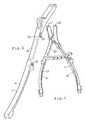
- FIG. 6is a perspective view of a fragment of FIG. 2, with parts added thereto.
- a parallel linkage assembly 16which is connected with, and is an extension of, the jaws 13 and 14 .
- the jaws proper 13 and 14have connecting posts 17 and 18 , and the assembly 16 is pivotally connected at the posts 17 and 18 through two links 19 and 21 .
- Two other links 22 and 23pivotally and slidably connect to the links 19 and 21 and are pivoted together at 24 .
- Links 23 and 24are pivoted to the respective links 19 and 21 , such as at 26 , and they also are slidably connected to the links 19 and 21 , such as at the slots 27 , to thereby maintain the links 13 and 14 in parallel relationship to each other throughout all degrees of movement of the jaws 13 and 14 as induced by the pivot action of the handles 10 and 11 .
- the links 19 and 21each have a recess 28 for full reception of the links 22 and 23 in the closed position, such as in FIG. 1 .
- the aforementioned arrangementis for distraction, and thus the workpiece, which is not shown but could be vertebrae, can be contacted by blades 29 removably attached to the extending ends of the links 19 and 21 .
- the blades 29are reversible in their mounting, and they have a snap-in connection at 30 so they can be reversed, and they are shown with an offset finger, such as disclosed in U.S. patent application Ser. No. 09/796,410, filed Mar. 2, 2002, and now U.S. Pat. No. 6,551,316, issued Apr. 22, 2003. Equal and directly opposed forces can be applied to the vertebrae, as desired.
- the instrumentcould also be used without the parallel linkage assembly 16 , such as arranged in FIG. 4 . Further it could be arranged with the jaws crossing over each other at the pivot 12 so that the jaws move toward each other upon squeezing the handles 10 and 11 . As such, it is then a compression instrument akin to the action of pliers.
- the first reading to appear, in response to squeezing the handles 10 and 11is the jaw spacing reading. That reading is on the scale 31 which is affixed to the handle 10 by a screws 32 and the scale 31 has an arcuate shape extending over the handle 11 when the instrument is in the maximum opening of the handles, as seen in FIG. 1 .
- scale 31has a face 34 on the convex arcuate extent, and the scale 31 carries indicia, such as the sequential numbers shown to be from “5” to “30”. In the handle wide open position, the reading at “5” aligns with a marker M affixed to the handle 11 .
- Both the scale 31 and the marker Mwill move in an arc upon initial pivoting of the handles 10 and 11 about the pivot axis 12 , thus the indicia on the scale 31 and the marker M will always be contiguous to each other for an accurate reading of the amount of pivot of the handles. That gives information about the amount of the spacing between the jaws 13 and 14 .
- the readingWith the jaws closed, as in FIGS. 1 and 3, the reading will be on the indicia “5” to reveal that the jaws are indeed closed in contact with each other and there is no space between the jaws 13 and 14 .
- Utilizing “5” etc. for the indiciais arbitrary and different indicia could be used, but scale graduation is significant to show the relative amount of jaw spacing.
- the marker Mwill pivotally move with the pivotal movement of the handle 11 . Later in this description and later in handle movement, it will be seen to be different from that.
- Two springs 36are respectively anchored on the handles 10 and 11 , and they contact each other at 37 .
- the springs 36therefore yielding urge the handles 10 and 11 away from each other, and to the jaw-closed position.
- the force of the springs 36is overcome by the user squeezing the handles 10 and 11 toward each other to open the jaws, as desired.
- Different spring openerscould be substituted.
- the jaw spacingcan be used to reveal the amount of space between two workpieces, or parts thereof, such as workpieces which might be in contact with the blades 29 in the distraction mode of the pliers, which is the mode shown herein.
- the plierscan be used on the workpiece in the nature of a caliper to measure a distance on the workpiece. The higher the aligned reading on the scale by the marker M the greater the spacing between the jaws.
- the handles 10 and 11have grip portions 41 along the lengths thereof which are rearward and approximately one-half the total length of the handles 10 and 11 , as best seen in the modified form in FIG. 4 .
- the scale 31 and marker Mare approximately at the intersection of the handle halves which are 41 and 42 .
- the grips 41have an abutment 43 which blocks the user's hand from obscuring the user's view of the scale 31 and marker M when the hand is gripping the grips 41 .
- the handlesare of rigid material, except as described later, so they can pivot in response to being squeezed together and forced apart by springs 36 .
- FIG. 2Another way of pivoting the handles 10 and 11 together, and then holding them at that pivoted position, is with a threaded rod 44 which is pivotally attached to the handle 11 at pin 46 and the rod 44 extends through handle 10 , such as seen in FIG. 2.
- a knob 47is threaded onto the rod 44 and the knob 47 can be positioned to abut the handle 10 and thereby secure the spacing of the handles 10 and 11 relative to each other and against the force of the springs 36 which urge the handles apart.
- the knob 47 and rod 44can be employed to threadedly move the knob along the rod and thereby force on the handles 10 and 11 to create the handle pivoting, as desired.
- the jaws 19 and 21When the jaws 19 and 21 , having thereon any attachments for contacting a workpiece, such as attachments 29 and such as in the cited patent above, engage the workpiece, they basically have no further movement. That is, they abut the workpiece, and that can be when the pliers is arranged for either mode of compression or distraction, per the cited patent and the description herein. In either mode, the handles will always be squeezed together to apply the force on the workpiece, and the jaws 19 and 21 will move either toward or away from each other.
- the handle 11is constructed to have a resilient length for its inner portion or approximate half the length of the handle 11 as seen at 49 .
- the handle 11has a rigid length 51 extending from the pivot 12 , and that length 51 is connected with the resilient length 49 which is connected with the grip 41 of the handle 11 .
- the handle 11is continuous from its extent from the pivot 12 to the pivot 46 , but the length 49 is resilient.
- the portion 49can be of a spring steel material, or any other material that provides the resilience desired herein.
- the length 49is sufficiently firm to pivot with the pivoting handle 11 until resistance is presented by the workpiece. Therefore, there is an accurate showing on the scale 52 of the amount of pivot of the handles relative to workpiece contact, and that amount of pivot is shown on the scale 31 .
- the workpiecewill present a resistance to further movement of jaw 16 and that is when further squeezing on the handles 10 and 11 will cause the resilient portion to flex in proportion to the force being applied by squeezing or threadedly forcing on the handles, and that flexing is in accord with the force applied to the workpiece.
- the workpiecemay either move or remain in position of initial contact, depending on its own sturdiness.
- An elongated pointer 53is attached to the handle rigid portion 51 and extends to the scale 52 where it terminates in an arrowhead 54 .
- the pointer 53always extends in only one direction of from the portion 51 in that it always retains its pointing direction off portion 51 as shown in the drawings, it does not deviate from that shown pointed direction relative to portion 51 .
- FIG. 3shows that the pointer 53 is nested in a recess defined by two spaced-apart shoulders 56 , so the pointer 53 cannot pivot or otherwise move relative to the handle portion 51 .
- a screw 57holds the pointer down into the recess defined by the two shoulders 56 .
- the marker Mis on the extending end or arrowhead 54 of the pointer 53 , so it too remains in its shown and set position throughout the operation of this instrument.
- the material 49can flex to move the scale 52 relative to the stationary pointer 54 . That is, the scale 52 will show the measurement of the flexing force, per the indicia “0” to “4” to reveal to the user the amount of force that is being applied to the workpiece.
- the handle 11has the scale 52 and the pointer 53 , along with a resilience that allows bending of the handle, to reveal a reading regarding the force being applied to the workpiece. Under additional force, the handle 11 bends from the position shown in the drawings. Upon release of the pivoting force, the handle returns to the position shown, which is a zero position. Throughout, the pointer always remains set in its shown position.
- this instrumentcould be where the workpiece has two separated portions, such as with vertebrae, and the distraction mode will detect the spacing between the two adjacent vertebrae, on the scale 31 , and then it will also detect the amount of force applied when the handles are pivoted until the resilient portion 49 becomes active, as shown on the scale 52 .
Landscapes
- Health & Medical Sciences (AREA)
- Surgery (AREA)
- Life Sciences & Earth Sciences (AREA)
- Biomedical Technology (AREA)
- Nuclear Medicine, Radiotherapy & Molecular Imaging (AREA)
- Engineering & Computer Science (AREA)
- Heart & Thoracic Surgery (AREA)
- Medical Informatics (AREA)
- Molecular Biology (AREA)
- Animal Behavior & Ethology (AREA)
- General Health & Medical Sciences (AREA)
- Public Health (AREA)
- Veterinary Medicine (AREA)
- Ophthalmology & Optometry (AREA)
- Dental Tools And Instruments Or Auxiliary Dental Instruments (AREA)
Abstract
Description
Claims (23)
Priority Applications (1)
| Application Number | Priority Date | Filing Date | Title |
|---|---|---|---|
| US10/336,677US6739068B1 (en) | 2003-01-06 | 2003-01-06 | Pliers with jaw spacing and load measuring readings |
Applications Claiming Priority (1)
| Application Number | Priority Date | Filing Date | Title |
|---|---|---|---|
| US10/336,677US6739068B1 (en) | 2003-01-06 | 2003-01-06 | Pliers with jaw spacing and load measuring readings |
Publications (1)
| Publication Number | Publication Date |
|---|---|
| US6739068B1true US6739068B1 (en) | 2004-05-25 |
Family
ID=32312336
Family Applications (1)
| Application Number | Title | Priority Date | Filing Date |
|---|---|---|---|
| US10/336,677Expired - LifetimeUS6739068B1 (en) | 2003-01-06 | 2003-01-06 | Pliers with jaw spacing and load measuring readings |
Country Status (1)
| Country | Link |
|---|---|
| US (1) | US6739068B1 (en) |
Cited By (91)
| Publication number | Priority date | Publication date | Assignee | Title |
|---|---|---|---|---|
| US20060074432A1 (en)* | 2004-10-06 | 2006-04-06 | Depuy Spine, Inc. | Modular medical tool and connector |
| US20060074431A1 (en)* | 2004-09-28 | 2006-04-06 | Depuy Spine, Inc. | Disc distraction instrument and measuring device |
| EP1652479A1 (en)* | 2004-10-27 | 2006-05-03 | BrainLAB AG | Spine distractor with markers |
| US20060149278A1 (en)* | 2004-11-24 | 2006-07-06 | Abdou Amy M | Devices and methods for inter-vertebral orthopedic device placement |
| US20060235427A1 (en)* | 2005-04-14 | 2006-10-19 | Thomas Bradley G | Multi-function orthopedic instrument |
| US20060247648A1 (en)* | 2005-04-29 | 2006-11-02 | Sdgi Holdings, Inc. | Surgical instrument and method |
| US20060247668A1 (en)* | 2005-04-28 | 2006-11-02 | Park Kee B | Surgical tool |
| WO2006014384A3 (en)* | 2004-07-02 | 2006-12-21 | Hfsc Co | Compressor-distractor |
| US20070093828A1 (en)* | 2005-10-07 | 2007-04-26 | Abdou M S | Devices and methods for inter-vertebral orthopedic device placement |
| US20070157484A1 (en)* | 2006-01-09 | 2007-07-12 | Grubler Michael J | Nut/bolt measuring device |
| US20070173855A1 (en)* | 2006-01-17 | 2007-07-26 | Sdgi Holdings, Inc. | Devices and methods for spacing of vertebral members over multiple levels |
| US20080027438A1 (en)* | 2006-07-27 | 2008-01-31 | Abdou M S | Devices and methods for the minimally invasive treatment of spinal stenosis |
| US20090056160A1 (en)* | 2007-09-04 | 2009-03-05 | Bobby Hu | Caliper |
| US20090198240A1 (en)* | 2008-01-31 | 2009-08-06 | Kaufman David L | Femoral Tibial Spreader with Tensor Measurement |
| EP1901654A4 (en)* | 2005-07-12 | 2009-09-16 | Kyphon Inc | MEASURING INSTRUMENT FOR PERCUTANEOUS OPERATIONS |
| US20100016906A1 (en)* | 2008-07-21 | 2010-01-21 | Abdou M Samy | Device and method to access the anterior column of the spine |
| US20100069929A1 (en)* | 2004-05-03 | 2010-03-18 | Abdou M S | Devices and methods for the preservation of spinal prosthesis function |
| US20100106250A1 (en)* | 2004-08-23 | 2010-04-29 | Abdou M Samy | Bone fixation and fusion device |
| US20100211177A1 (en)* | 2004-10-05 | 2010-08-19 | Abdou M Samy | Devices and methods for inter-vertebral orthopedic device placement |
| US20100328098A1 (en)* | 2009-06-30 | 2010-12-30 | Orthosensor | System and method for integrated antenna in a sensing module for measurement of the muscular-skeletal system |
| CN101940481A (en)* | 2010-09-09 | 2011-01-12 | 成都春江科技有限公司 | Parallel surgical spreader |
| US20110119946A1 (en)* | 2009-11-24 | 2011-05-26 | Leo Duarte | Digital sizing tool |
| US20110153024A1 (en)* | 2009-12-17 | 2011-06-23 | Zimmer, Inc. | Modular elbow prosthesis |
| EP1974771A4 (en)* | 2006-01-18 | 2011-12-21 | Chongqing Haifu Hifu Tech Co | Ultrasonic treatment clamp |
| US8202299B2 (en)* | 2008-03-19 | 2012-06-19 | Collabcom II, LLC | Interspinous implant, tools and methods of implanting |
| US8516884B2 (en) | 2010-06-29 | 2013-08-27 | Orthosensor Inc. | Shielded prosthetic component |
| US8539830B2 (en) | 2010-06-29 | 2013-09-24 | Orthosensor Inc. | High precision sensing for parameter measurement of bone density |
| US8661893B2 (en) | 2010-06-29 | 2014-03-04 | Orthosensor Inc. | Prosthetic component having a compliant surface |
| US8679186B2 (en) | 2010-06-29 | 2014-03-25 | Ortho Sensor Inc. | Hermetically sealed prosthetic component and method therefor |
| US8690888B2 (en) | 2011-09-23 | 2014-04-08 | Orthosensor Inc. | Modular active spine tool for measuring vertebral load and position of load |
| US8696756B2 (en) | 2010-06-29 | 2014-04-15 | Orthosensor Inc. | Muscular-skeletal force, pressure, and load measurement system and method |
| US8701484B2 (en) | 2010-06-29 | 2014-04-22 | Orthosensor Inc. | Small form factor medical sensor structure and method therefor |
| US8707782B2 (en) | 2009-06-30 | 2014-04-29 | Orthosensor Inc | Prosthetic component for monitoring synovial fluid and method |
| US8714009B2 (en) | 2010-06-29 | 2014-05-06 | Orthosensor Inc. | Shielded capacitor sensor system for medical applications and method |
| US8720270B2 (en) | 2010-06-29 | 2014-05-13 | Ortho Sensor Inc. | Prosthetic component for monitoring joint health |
| US8746062B2 (en) | 2010-06-29 | 2014-06-10 | Orthosensor Inc. | Medical measurement system and method |
| US8777953B1 (en) | 2010-10-06 | 2014-07-15 | Greatbatch Ltd. | Rocker mechanism |
| US20140214043A1 (en)* | 2013-01-31 | 2014-07-31 | Warsaw Orthopedic, Inc. | Surgical spacer instrument and method |
| US8795335B1 (en) | 2009-11-06 | 2014-08-05 | Samy Abdou | Spinal fixation devices and methods of use |
| US8826733B2 (en) | 2009-06-30 | 2014-09-09 | Orthosensor Inc | Sensored prosthetic component and method |
| WO2014153525A3 (en)* | 2013-03-21 | 2014-11-13 | Old Dominion University Research Foundation, | Device for detection of internal body force on an implanted bar |
| US8936647B2 (en) | 2012-06-22 | 2015-01-20 | Zimmer, Inc. | Elbow prosthesis |
| US8939030B2 (en) | 2010-06-29 | 2015-01-27 | Orthosensor Inc | Edge-detect receiver for orthopedic parameter sensing |
| US8945133B2 (en) | 2011-09-23 | 2015-02-03 | Orthosensor Inc | Spinal distraction tool for load and position measurement |
| US8951258B2 (en) | 2013-03-01 | 2015-02-10 | Warsaw Orthopedic, Inc. | Spinal correction system and method |
| EP2775952A4 (en)* | 2011-11-08 | 2015-08-12 | Olympus Corp | Medical treatment tool and manipulator including the same |
| US9161717B2 (en) | 2011-09-23 | 2015-10-20 | Orthosensor Inc. | Orthopedic insert measuring system having a sealed cavity |
| US9168073B2 (en) | 2013-03-15 | 2015-10-27 | DePuy Synthes Products, Inc. | Spinous process fixator |
| US9259172B2 (en) | 2013-03-18 | 2016-02-16 | Orthosensor Inc. | Method of providing feedback to an orthopedic alignment system |
| US9259179B2 (en) | 2012-02-27 | 2016-02-16 | Orthosensor Inc. | Prosthetic knee joint measurement system including energy harvesting and method therefor |
| US9271675B2 (en) | 2012-02-27 | 2016-03-01 | Orthosensor Inc. | Muscular-skeletal joint stability detection and method therefor |
| US9414940B2 (en) | 2011-09-23 | 2016-08-16 | Orthosensor Inc. | Sensored head for a measurement tool for the muscular-skeletal system |
| CN105943219A (en)* | 2016-05-16 | 2016-09-21 | 河北医科大学第三医院 | Calcaneus bone fracture compression restoration device |
| US9462964B2 (en) | 2011-09-23 | 2016-10-11 | Orthosensor Inc | Small form factor muscular-skeletal parameter measurement system |
| USRE46261E1 (en)* | 2007-12-19 | 2017-01-03 | DePuy Synthes Products, Inc. | Instruments for expandable corpectomy spinal fusion cage |
| US9622701B2 (en) | 2012-02-27 | 2017-04-18 | Orthosensor Inc | Muscular-skeletal joint stability detection and method therefor |
| TWI586331B (en)* | 2014-02-14 | 2017-06-11 | 蘇峻良 | Foreskin force shape variable measuring device and measuring method |
| US9757051B2 (en) | 2012-11-09 | 2017-09-12 | Orthosensor Inc. | Muscular-skeletal tracking system and method |
| US9839390B2 (en) | 2009-06-30 | 2017-12-12 | Orthosensor Inc. | Prosthetic component having a compliant surface |
| US9839374B2 (en) | 2011-09-23 | 2017-12-12 | Orthosensor Inc. | System and method for vertebral load and location sensing |
| US9844335B2 (en) | 2012-02-27 | 2017-12-19 | Orthosensor Inc | Measurement device for the muscular-skeletal system having load distribution plates |
| US9907579B2 (en) | 2008-08-13 | 2018-03-06 | DePuy Synthes Products, Inc. | Interspinous spacer assembly |
| US9937062B2 (en) | 2011-09-23 | 2018-04-10 | Orthosensor Inc | Device and method for enabling an orthopedic tool for parameter measurement |
| US10004449B2 (en) | 2012-02-27 | 2018-06-26 | Orthosensor Inc. | Measurement device for the muscular-skeletal system having alignment features |
| US10201374B2 (en) | 2012-06-22 | 2019-02-12 | Zimmer, Inc. | Assembly tool for a prosthesis |
| US10307893B2 (en) | 2015-12-14 | 2019-06-04 | Dimide, Inc. | Clamping apparatus and method |
| TWI665433B (en)* | 2018-12-03 | 2019-07-11 | 中國鋼鐵股份有限公司 | Water pipe clamp performance test system and test method |
| US10398477B2 (en)* | 2006-04-03 | 2019-09-03 | Ib Medical, Llc | Static compression device |
| US10426460B2 (en) | 2016-07-05 | 2019-10-01 | Mortise Medical, LLC | Compression and tension instruments and methods of use to reinforce ligaments |
| US10543107B2 (en) | 2009-12-07 | 2020-01-28 | Samy Abdou | Devices and methods for minimally invasive spinal stabilization and instrumentation |
| US10548740B1 (en) | 2016-10-25 | 2020-02-04 | Samy Abdou | Devices and methods for vertebral bone realignment |
| US10575961B1 (en) | 2011-09-23 | 2020-03-03 | Samy Abdou | Spinal fixation devices and methods of use |
| US10695105B2 (en) | 2012-08-28 | 2020-06-30 | Samy Abdou | Spinal fixation devices and methods of use |
| US10736672B2 (en) | 2017-05-25 | 2020-08-11 | Warsaw Orthopedic, Inc. | Spinal implant system and method |
| US10842432B2 (en) | 2017-09-14 | 2020-11-24 | Orthosensor Inc. | Medial-lateral insert sensing system with common module and method therefor |
| US10857003B1 (en) | 2015-10-14 | 2020-12-08 | Samy Abdou | Devices and methods for vertebral stabilization |
| US10973648B1 (en) | 2016-10-25 | 2021-04-13 | Samy Abdou | Devices and methods for vertebral bone realignment |
| US11006982B2 (en) | 2012-02-22 | 2021-05-18 | Samy Abdou | Spinous process fixation devices and methods of use |
| US11173040B2 (en) | 2012-10-22 | 2021-11-16 | Cogent Spine, LLC | Devices and methods for spinal stabilization and instrumentation |
| US11179248B2 (en) | 2018-10-02 | 2021-11-23 | Samy Abdou | Devices and methods for spinal implantation |
| US20220167999A1 (en) | 2018-12-13 | 2022-06-02 | Paragon 28, Inc. | Alignment instruments and methods for use in total ankle replacement |
| US11382671B2 (en) | 2019-06-25 | 2022-07-12 | Warsaw Orthopedic, Inc. | Surgical instrument and method |
| US11399949B2 (en) | 2018-12-13 | 2022-08-02 | Paragon 28, Inc. | Total ankle replacement trial and preparation systems, guides, instruments and related methods |
| US11419595B2 (en)* | 2017-05-19 | 2022-08-23 | Paradigm Spine, Llc | Interspinous, interlaminar space expander and measurement instrument |
| US11464522B2 (en)* | 2018-12-13 | 2022-10-11 | Paragon 28, Inc. | Distractors having attachable paddles, impaction devices, and methods for use in total ankle replacement |
| US11793424B2 (en) | 2013-03-18 | 2023-10-24 | Orthosensor, Inc. | Kinetic assessment and alignment of the muscular-skeletal system and method therefor |
| US11812978B2 (en) | 2019-10-15 | 2023-11-14 | Orthosensor Inc. | Knee balancing system using patient specific instruments |
| CN118697474A (en)* | 2024-09-02 | 2024-09-27 | 北京维卓致远医疗科技股份有限公司 | A tracer fixing fixture for surgical navigation |
| US12133804B2 (en) | 2018-12-13 | 2024-11-05 | Paragon 28, Inc. | Total ankle replacement surgical method |
| US12156664B2 (en) | 2018-12-13 | 2024-12-03 | Paragon 28, Inc. | Resection guides, sweeping reamers, and methods for use in total ankle replacement |
| US12239550B2 (en) | 2018-12-13 | 2025-03-04 | Paragon 28, Inc. | Joint replacement alignment guides, systems and methods of use and assembly |
Citations (37)
| Publication number | Priority date | Publication date | Assignee | Title |
|---|---|---|---|---|
| US466986A (en) | 1892-01-12 | Calipers for bracelets | ||
| US1528273A (en) | 1921-06-17 | 1925-03-03 | Shwed David | Measuring device |
| US1626540A (en) | 1924-06-18 | 1927-04-26 | Kimura Lawrence Yasukichi | Pivoted-type compass |
| US2112873A (en) | 1936-11-07 | 1938-04-05 | Wright Jerauld | Tool |
| US2125945A (en) | 1937-12-21 | 1938-08-09 | Walter H Montgomery | Torque indication wrench |
| US2396619A (en) | 1944-01-10 | 1946-03-12 | White S Dental Mfg Co | Orthodontic implement |
| US2591360A (en) | 1948-12-30 | 1952-04-01 | Joseph D Keenan | Handle means for simultaneous operation of double-ended pliers |
| US2888825A (en) | 1955-11-14 | 1959-06-02 | Joseph M Krafft | Device for determining axial force exerted by a screw from torque measurements |
| US3140546A (en) | 1962-07-05 | 1964-07-14 | Lloyd Cleveland Bartlett | Skin fold caliper |
| US3140715A (en) | 1960-09-29 | 1964-07-14 | American Hospital Supply Corp | Forceps |
| US3391573A (en) | 1966-04-04 | 1968-07-09 | John B. Hiller | Torque wrench indicator and compensator |
| US3559515A (en) | 1967-12-20 | 1971-02-02 | Aircraft Specialties Inc | Self gripping needle-nose plier |
| US3740779A (en) | 1971-11-26 | 1973-06-26 | Leveen H | Surgical device |
| US4050464A (en) | 1975-04-28 | 1977-09-27 | Downs Surgical Limited | Surgical cable tensioning instrument |
| US4127112A (en) | 1977-04-06 | 1978-11-28 | American Hospital Supply Corp. | Skin fold caliper |
| US4184259A (en) | 1977-06-13 | 1980-01-22 | Sosnay Alan J | Orthodontic tool for placing twists in arch wires |
| US4226025A (en) | 1979-03-05 | 1980-10-07 | Wheeler Michael R | Surgical caliper |
| US4312363A (en) | 1980-02-26 | 1982-01-26 | Senco Products, Inc. | Surgical tissue thickness measuring instrument |
| US4432376A (en)* | 1980-01-30 | 1984-02-21 | Huszar Gabor B | Method for determining the extensibility of selected non-excised tissue of the uterine cervix, ear or skin |
| US4633587A (en) | 1984-06-16 | 1987-01-06 | Wilkinson Sword Limited Of Sword House | Spring-biased garden pruners |
| US4843721A (en) | 1987-05-22 | 1989-07-04 | Enerwest, Inc. | Measuring device |
| US4898161A (en)* | 1986-12-05 | 1990-02-06 | S+G Implants Gmbh | Forceps for pushing apart vertebrae |
| US5070623A (en) | 1990-05-02 | 1991-12-10 | Zimmer, Inc. | Prosthetic gauge |
| US5116340A (en) | 1989-01-26 | 1992-05-26 | Songer Robert J | Surgical securance apparatus |
| US5156161A (en) | 1991-08-02 | 1992-10-20 | Lollar John A | Skinfold caliper for body fat measurement |
| US5183055A (en) | 1991-12-27 | 1993-02-02 | Seager Stephen W J | Device for obtaining testicular or penile size and volume measurements |
| US5297538A (en)* | 1992-04-10 | 1994-03-29 | Daniel Elie C | Surgical retractor/compressor |
| US5336228A (en) | 1992-01-14 | 1994-08-09 | Cholhan Hilary J | Cervical manipulator forceps |
| US5381799A (en) | 1994-01-14 | 1995-01-17 | The Procter & Gamble Company | Inexpensive and easy to use mechanically operated bite force gauge |
| US5433015A (en)* | 1993-07-15 | 1995-07-18 | Societe Nationale D'etude Et De Construction De Moteurs D'aviation "Snecma" | Tool for measuring a clamping force exerted by a movable spindle of a length measuring instrument |
| US5597305A (en) | 1995-06-12 | 1997-01-28 | Ray, Sr.; Charles M. | Dental wrench |
| US5658295A (en) | 1996-06-03 | 1997-08-19 | Krementsov; Yury | Instrument for measuring dilatation of cervix uteri |
| US6048322A (en) | 1998-04-15 | 2000-04-11 | Kushida; Clete | Morphometric measurement tool |
| US6102909A (en)* | 1997-08-26 | 2000-08-15 | Ethicon, Inc. | Scissorlike electrosurgical cutting instrument |
| US6263770B1 (en) | 1998-02-27 | 2001-07-24 | Bost Garnache Industries | Tool comprising a damping and/or opening spring |
| US6551316B1 (en)* | 2001-03-02 | 2003-04-22 | Beere Precision Medical Instruments, Inc. | Selective compression and distraction instrument |
| US6553685B2 (en)* | 2000-07-26 | 2003-04-29 | Mitutoyo Corporation | Measuring instruments |
- 2003
- 2003-01-06USUS10/336,677patent/US6739068B1/ennot_activeExpired - Lifetime
Patent Citations (37)
| Publication number | Priority date | Publication date | Assignee | Title |
|---|---|---|---|---|
| US466986A (en) | 1892-01-12 | Calipers for bracelets | ||
| US1528273A (en) | 1921-06-17 | 1925-03-03 | Shwed David | Measuring device |
| US1626540A (en) | 1924-06-18 | 1927-04-26 | Kimura Lawrence Yasukichi | Pivoted-type compass |
| US2112873A (en) | 1936-11-07 | 1938-04-05 | Wright Jerauld | Tool |
| US2125945A (en) | 1937-12-21 | 1938-08-09 | Walter H Montgomery | Torque indication wrench |
| US2396619A (en) | 1944-01-10 | 1946-03-12 | White S Dental Mfg Co | Orthodontic implement |
| US2591360A (en) | 1948-12-30 | 1952-04-01 | Joseph D Keenan | Handle means for simultaneous operation of double-ended pliers |
| US2888825A (en) | 1955-11-14 | 1959-06-02 | Joseph M Krafft | Device for determining axial force exerted by a screw from torque measurements |
| US3140715A (en) | 1960-09-29 | 1964-07-14 | American Hospital Supply Corp | Forceps |
| US3140546A (en) | 1962-07-05 | 1964-07-14 | Lloyd Cleveland Bartlett | Skin fold caliper |
| US3391573A (en) | 1966-04-04 | 1968-07-09 | John B. Hiller | Torque wrench indicator and compensator |
| US3559515A (en) | 1967-12-20 | 1971-02-02 | Aircraft Specialties Inc | Self gripping needle-nose plier |
| US3740779A (en) | 1971-11-26 | 1973-06-26 | Leveen H | Surgical device |
| US4050464A (en) | 1975-04-28 | 1977-09-27 | Downs Surgical Limited | Surgical cable tensioning instrument |
| US4127112A (en) | 1977-04-06 | 1978-11-28 | American Hospital Supply Corp. | Skin fold caliper |
| US4184259A (en) | 1977-06-13 | 1980-01-22 | Sosnay Alan J | Orthodontic tool for placing twists in arch wires |
| US4226025A (en) | 1979-03-05 | 1980-10-07 | Wheeler Michael R | Surgical caliper |
| US4432376A (en)* | 1980-01-30 | 1984-02-21 | Huszar Gabor B | Method for determining the extensibility of selected non-excised tissue of the uterine cervix, ear or skin |
| US4312363A (en) | 1980-02-26 | 1982-01-26 | Senco Products, Inc. | Surgical tissue thickness measuring instrument |
| US4633587A (en) | 1984-06-16 | 1987-01-06 | Wilkinson Sword Limited Of Sword House | Spring-biased garden pruners |
| US4898161A (en)* | 1986-12-05 | 1990-02-06 | S+G Implants Gmbh | Forceps for pushing apart vertebrae |
| US4843721A (en) | 1987-05-22 | 1989-07-04 | Enerwest, Inc. | Measuring device |
| US5116340A (en) | 1989-01-26 | 1992-05-26 | Songer Robert J | Surgical securance apparatus |
| US5070623A (en) | 1990-05-02 | 1991-12-10 | Zimmer, Inc. | Prosthetic gauge |
| US5156161A (en) | 1991-08-02 | 1992-10-20 | Lollar John A | Skinfold caliper for body fat measurement |
| US5183055A (en) | 1991-12-27 | 1993-02-02 | Seager Stephen W J | Device for obtaining testicular or penile size and volume measurements |
| US5336228A (en) | 1992-01-14 | 1994-08-09 | Cholhan Hilary J | Cervical manipulator forceps |
| US5297538A (en)* | 1992-04-10 | 1994-03-29 | Daniel Elie C | Surgical retractor/compressor |
| US5433015A (en)* | 1993-07-15 | 1995-07-18 | Societe Nationale D'etude Et De Construction De Moteurs D'aviation "Snecma" | Tool for measuring a clamping force exerted by a movable spindle of a length measuring instrument |
| US5381799A (en) | 1994-01-14 | 1995-01-17 | The Procter & Gamble Company | Inexpensive and easy to use mechanically operated bite force gauge |
| US5597305A (en) | 1995-06-12 | 1997-01-28 | Ray, Sr.; Charles M. | Dental wrench |
| US5658295A (en) | 1996-06-03 | 1997-08-19 | Krementsov; Yury | Instrument for measuring dilatation of cervix uteri |
| US6102909A (en)* | 1997-08-26 | 2000-08-15 | Ethicon, Inc. | Scissorlike electrosurgical cutting instrument |
| US6263770B1 (en) | 1998-02-27 | 2001-07-24 | Bost Garnache Industries | Tool comprising a damping and/or opening spring |
| US6048322A (en) | 1998-04-15 | 2000-04-11 | Kushida; Clete | Morphometric measurement tool |
| US6553685B2 (en)* | 2000-07-26 | 2003-04-29 | Mitutoyo Corporation | Measuring instruments |
| US6551316B1 (en)* | 2001-03-02 | 2003-04-22 | Beere Precision Medical Instruments, Inc. | Selective compression and distraction instrument |
Cited By (183)
| Publication number | Priority date | Publication date | Assignee | Title |
|---|---|---|---|---|
| US20100069929A1 (en)* | 2004-05-03 | 2010-03-18 | Abdou M S | Devices and methods for the preservation of spinal prosthesis function |
| US8753348B2 (en) | 2004-07-02 | 2014-06-17 | DePuy Synthes Products, LLC | Compressor-distractor |
| US20140243903A1 (en)* | 2004-07-02 | 2014-08-28 | DePuy Synthes Products, LLC | Compressor-distractor |
| KR101189728B1 (en) | 2004-07-02 | 2012-10-11 | 신세스 게엠바하 | Compressor-distractor |
| JP4809834B2 (en)* | 2004-07-02 | 2011-11-09 | ジンテス ゲゼルシャフト ミット ベシュレンクテル ハフツング | Compression / distraction device |
| CN100542496C (en)* | 2004-07-02 | 2009-09-23 | 芯赛斯公司 | Compressor-retractor |
| WO2006014384A3 (en)* | 2004-07-02 | 2006-12-21 | Hfsc Co | Compressor-distractor |
| JP2008504935A (en)* | 2004-07-02 | 2008-02-21 | ジンテス ゲゼルシャフト ミット ベシュレンクテル ハフツング | Compression / distraction device |
| US9351773B2 (en)* | 2004-07-02 | 2016-05-31 | DePuy Synthes Products, Inc. | Compressor-distractor |
| US10470892B2 (en) | 2004-08-23 | 2019-11-12 | Samy Abdou | Bone fixation and fusion device |
| US9060873B2 (en) | 2004-08-23 | 2015-06-23 | M. Samy Abdou | Bone fixation and fusion device |
| US20100106250A1 (en)* | 2004-08-23 | 2010-04-29 | Abdou M Samy | Bone fixation and fusion device |
| US20060074431A1 (en)* | 2004-09-28 | 2006-04-06 | Depuy Spine, Inc. | Disc distraction instrument and measuring device |
| US8673013B2 (en) | 2004-10-05 | 2014-03-18 | Samy Abdou | Devices and methods for inter-vertebral orthopedic device placement |
| US20100211177A1 (en)* | 2004-10-05 | 2010-08-19 | Abdou M Samy | Devices and methods for inter-vertebral orthopedic device placement |
| US8292896B2 (en) | 2004-10-05 | 2012-10-23 | Abdou M Samy | Devices and methods for inter-vertebral orthopedic device placement |
| US20060074432A1 (en)* | 2004-10-06 | 2006-04-06 | Depuy Spine, Inc. | Modular medical tool and connector |
| US8979857B2 (en)* | 2004-10-06 | 2015-03-17 | DePuy Synthes Products, LLC | Modular medical tool and connector |
| US8043295B2 (en) | 2004-10-27 | 2011-10-25 | Brainlab Ag | Vertebral spreading instrument comprising markers |
| EP1652479A1 (en)* | 2004-10-27 | 2006-05-03 | BrainLAB AG | Spine distractor with markers |
| US20060264963A1 (en)* | 2004-10-27 | 2006-11-23 | Peter Reed | Vertebral spreading instrument comprising markers |
| US11992423B2 (en) | 2004-11-24 | 2024-05-28 | Samy Abdou | Devices and methods for inter-vertebral orthopedic device placement |
| US10188529B2 (en) | 2004-11-24 | 2019-01-29 | Samy Abdou | Devices and methods for inter-vertebral orthopedic device placement |
| US8172855B2 (en) | 2004-11-24 | 2012-05-08 | Abdou M S | Devices and methods for inter-vertebral orthopedic device placement |
| US8974461B2 (en) | 2004-11-24 | 2015-03-10 | M. Samy Abdou | Devices and methods for inter-vertebral orthopedic device placement |
| EP1814474A4 (en)* | 2004-11-24 | 2008-12-10 | Samy M Abdou | Devices and methods for inter-vertebral orthopedic device placement |
| US11096799B2 (en) | 2004-11-24 | 2021-08-24 | Samy Abdou | Devices and methods for inter-vertebral orthopedic device placement |
| US10918498B2 (en) | 2004-11-24 | 2021-02-16 | Samy Abdou | Devices and methods for inter-vertebral orthopedic device placement |
| US20060149278A1 (en)* | 2004-11-24 | 2006-07-06 | Abdou Amy M | Devices and methods for inter-vertebral orthopedic device placement |
| US8668699B2 (en)* | 2005-04-14 | 2014-03-11 | Warsaw Orthopedic, Inc. | Multi-function orthopedic instrument |
| WO2007027209A1 (en)* | 2005-04-14 | 2007-03-08 | Warsaw Orthopedic, Inc. | Multi-function orthopedic instrument |
| US20060235427A1 (en)* | 2005-04-14 | 2006-10-19 | Thomas Bradley G | Multi-function orthopedic instrument |
| US20060247668A1 (en)* | 2005-04-28 | 2006-11-02 | Park Kee B | Surgical tool |
| US20060247648A1 (en)* | 2005-04-29 | 2006-11-02 | Sdgi Holdings, Inc. | Surgical instrument and method |
| US7615052B2 (en)* | 2005-04-29 | 2009-11-10 | Warsaw Orthopedic, Inc. | Surgical instrument and method |
| EP1901654A4 (en)* | 2005-07-12 | 2009-09-16 | Kyphon Inc | MEASURING INSTRUMENT FOR PERCUTANEOUS OPERATIONS |
| US20070093828A1 (en)* | 2005-10-07 | 2007-04-26 | Abdou M S | Devices and methods for inter-vertebral orthopedic device placement |
| US8870920B2 (en) | 2005-10-07 | 2014-10-28 | M. Samy Abdou | Devices and methods for inter-vertebral orthopedic device placement |
| US20070157484A1 (en)* | 2006-01-09 | 2007-07-12 | Grubler Michael J | Nut/bolt measuring device |
| US20070173855A1 (en)* | 2006-01-17 | 2007-07-26 | Sdgi Holdings, Inc. | Devices and methods for spacing of vertebral members over multiple levels |
| EP1974771A4 (en)* | 2006-01-18 | 2011-12-21 | Chongqing Haifu Hifu Tech Co | Ultrasonic treatment clamp |
| US10398477B2 (en)* | 2006-04-03 | 2019-09-03 | Ib Medical, Llc | Static compression device |
| US8303630B2 (en) | 2006-07-27 | 2012-11-06 | Samy Abdou | Devices and methods for the minimally invasive treatment of spinal stenosis |
| US20080027438A1 (en)* | 2006-07-27 | 2008-01-31 | Abdou M S | Devices and methods for the minimally invasive treatment of spinal stenosis |
| US20090056160A1 (en)* | 2007-09-04 | 2009-03-05 | Bobby Hu | Caliper |
| US7509754B2 (en)* | 2007-09-04 | 2009-03-31 | Bobby Hu | Caliper |
| USRE46261E1 (en)* | 2007-12-19 | 2017-01-03 | DePuy Synthes Products, Inc. | Instruments for expandable corpectomy spinal fusion cage |
| US8162951B2 (en)* | 2008-01-31 | 2012-04-24 | Innomed, Inc. | Femoral tibial spreader with tensor measurement |
| US20090198240A1 (en)* | 2008-01-31 | 2009-08-06 | Kaufman David L | Femoral Tibial Spreader with Tensor Measurement |
| US8721688B1 (en) | 2008-03-19 | 2014-05-13 | Collabcom II, LLC | Interspinous implant, tools and methods of implanting |
| US8202299B2 (en)* | 2008-03-19 | 2012-06-19 | Collabcom II, LLC | Interspinous implant, tools and methods of implanting |
| US20100016906A1 (en)* | 2008-07-21 | 2010-01-21 | Abdou M Samy | Device and method to access the anterior column of the spine |
| US9907579B2 (en) | 2008-08-13 | 2018-03-06 | DePuy Synthes Products, Inc. | Interspinous spacer assembly |
| US9943265B2 (en) | 2009-06-30 | 2018-04-17 | Orthosensor Inc. | Integrated sensor for medical applications |
| US9289163B2 (en) | 2009-06-30 | 2016-03-22 | Orthosensor Inc. | Prosthetic component for monitoring synovial fluid and method |
| US9345492B2 (en) | 2009-06-30 | 2016-05-24 | Orthosensor Inc. | Shielded capacitor sensor system for medical applications and method |
| US9345449B2 (en) | 2009-06-30 | 2016-05-24 | Orthosensor Inc | Prosthetic component for monitoring joint health |
| US8707782B2 (en) | 2009-06-30 | 2014-04-29 | Orthosensor Inc | Prosthetic component for monitoring synovial fluid and method |
| US9226694B2 (en) | 2009-06-30 | 2016-01-05 | Orthosensor Inc | Small form factor medical sensor structure and method therefor |
| US9839390B2 (en) | 2009-06-30 | 2017-12-12 | Orthosensor Inc. | Prosthetic component having a compliant surface |
| US9358136B2 (en) | 2009-06-30 | 2016-06-07 | Orthosensor Inc. | Shielded capacitor sensor system for medical applications and method |
| US20100328098A1 (en)* | 2009-06-30 | 2010-12-30 | Orthosensor | System and method for integrated antenna in a sensing module for measurement of the muscular-skeletal system |
| US8826733B2 (en) | 2009-06-30 | 2014-09-09 | Orthosensor Inc | Sensored prosthetic component and method |
| US9119733B2 (en) | 2009-06-30 | 2015-09-01 | Orthosensor Inc. | Shielded prosthetic component |
| US9357964B2 (en) | 2009-06-30 | 2016-06-07 | Orthosensor Inc. | Hermetically sealed prosthetic component and method therefor |
| US9492115B2 (en) | 2009-06-30 | 2016-11-15 | Orthosensor Inc. | Sensored prosthetic component and method |
| US9492116B2 (en) | 2009-06-30 | 2016-11-15 | Orthosensor Inc. | Prosthetic knee joint measurement system including energy harvesting and method therefor |
| US9402583B2 (en) | 2009-06-30 | 2016-08-02 | Orthosensor Inc. | Orthopedic screw for measuring a parameter of the muscular-skeletal system |
| US8689647B2 (en) | 2009-06-30 | 2014-04-08 | Orthosensor Inc. | Sensing module having a piezo-resistive sensor for orthopedic load sensing insert device |
| US9375239B2 (en) | 2009-11-06 | 2016-06-28 | Samy Abdou | Spinal fixation devices and methods of use |
| US8795335B1 (en) | 2009-11-06 | 2014-08-05 | Samy Abdou | Spinal fixation devices and methods of use |
| US8024869B2 (en)* | 2009-11-24 | 2011-09-27 | Leo Duarte | Digital sizing tool |
| US20110119946A1 (en)* | 2009-11-24 | 2011-05-26 | Leo Duarte | Digital sizing tool |
| US10543107B2 (en) | 2009-12-07 | 2020-01-28 | Samy Abdou | Devices and methods for minimally invasive spinal stabilization and instrumentation |
| US10857004B2 (en) | 2009-12-07 | 2020-12-08 | Samy Abdou | Devices and methods for minimally invasive spinal stabilization and instrumentation |
| US10945861B2 (en) | 2009-12-07 | 2021-03-16 | Samy Abdou | Devices and methods for minimally invasive spinal stabilization and instrumentation |
| US11918486B2 (en) | 2009-12-07 | 2024-03-05 | Samy Abdou | Devices and methods for minimally invasive spinal stabilization and instrumentation |
| US10610380B2 (en) | 2009-12-07 | 2020-04-07 | Samy Abdou | Devices and methods for minimally invasive spinal stabilization and instrumentation |
| US8968411B2 (en) | 2009-12-17 | 2015-03-03 | Zimmer, Inc. | Modular elbow prosthesis |
| US20110153024A1 (en)* | 2009-12-17 | 2011-06-23 | Zimmer, Inc. | Modular elbow prosthesis |
| US8679186B2 (en) | 2010-06-29 | 2014-03-25 | Ortho Sensor Inc. | Hermetically sealed prosthetic component and method therefor |
| US8939030B2 (en) | 2010-06-29 | 2015-01-27 | Orthosensor Inc | Edge-detect receiver for orthopedic parameter sensing |
| US8714009B2 (en) | 2010-06-29 | 2014-05-06 | Orthosensor Inc. | Shielded capacitor sensor system for medical applications and method |
| US8746062B2 (en) | 2010-06-29 | 2014-06-10 | Orthosensor Inc. | Medical measurement system and method |
| US8516884B2 (en) | 2010-06-29 | 2013-08-27 | Orthosensor Inc. | Shielded prosthetic component |
| US8701484B2 (en) | 2010-06-29 | 2014-04-22 | Orthosensor Inc. | Small form factor medical sensor structure and method therefor |
| US8696756B2 (en) | 2010-06-29 | 2014-04-15 | Orthosensor Inc. | Muscular-skeletal force, pressure, and load measurement system and method |
| US8720270B2 (en) | 2010-06-29 | 2014-05-13 | Ortho Sensor Inc. | Prosthetic component for monitoring joint health |
| US8661893B2 (en) | 2010-06-29 | 2014-03-04 | Orthosensor Inc. | Prosthetic component having a compliant surface |
| US8539830B2 (en) | 2010-06-29 | 2013-09-24 | Orthosensor Inc. | High precision sensing for parameter measurement of bone density |
| CN101940481A (en)* | 2010-09-09 | 2011-01-12 | 成都春江科技有限公司 | Parallel surgical spreader |
| US8777953B1 (en) | 2010-10-06 | 2014-07-15 | Greatbatch Ltd. | Rocker mechanism |
| US8777877B2 (en) | 2011-09-23 | 2014-07-15 | Orthosensor Inc. | Spine tool for measuring vertebral load and position of load |
| US8945133B2 (en) | 2011-09-23 | 2015-02-03 | Orthosensor Inc | Spinal distraction tool for load and position measurement |
| US12167973B2 (en) | 2011-09-23 | 2024-12-17 | Samy Abdou | Spinal fixation devices and methods of use |
| US9462964B2 (en) | 2011-09-23 | 2016-10-11 | Orthosensor Inc | Small form factor muscular-skeletal parameter measurement system |
| US10575961B1 (en) | 2011-09-23 | 2020-03-03 | Samy Abdou | Spinal fixation devices and methods of use |
| US11517449B2 (en) | 2011-09-23 | 2022-12-06 | Samy Abdou | Spinal fixation devices and methods of use |
| US9414940B2 (en) | 2011-09-23 | 2016-08-16 | Orthosensor Inc. | Sensored head for a measurement tool for the muscular-skeletal system |
| US8690888B2 (en) | 2011-09-23 | 2014-04-08 | Orthosensor Inc. | Modular active spine tool for measuring vertebral load and position of load |
| US11324608B2 (en) | 2011-09-23 | 2022-05-10 | Samy Abdou | Spinal fixation devices and methods of use |
| US9161717B2 (en) | 2011-09-23 | 2015-10-20 | Orthosensor Inc. | Orthopedic insert measuring system having a sealed cavity |
| US9937062B2 (en) | 2011-09-23 | 2018-04-10 | Orthosensor Inc | Device and method for enabling an orthopedic tool for parameter measurement |
| US8784339B2 (en) | 2011-09-23 | 2014-07-22 | Orthosensor Inc | Spinal instrument for measuring load and position of load |
| US9839374B2 (en) | 2011-09-23 | 2017-12-12 | Orthosensor Inc. | System and method for vertebral load and location sensing |
| EP2775952A4 (en)* | 2011-11-08 | 2015-08-12 | Olympus Corp | Medical treatment tool and manipulator including the same |
| US11839413B2 (en) | 2012-02-22 | 2023-12-12 | Samy Abdou | Spinous process fixation devices and methods of use |
| US11006982B2 (en) | 2012-02-22 | 2021-05-18 | Samy Abdou | Spinous process fixation devices and methods of use |
| US9271675B2 (en) | 2012-02-27 | 2016-03-01 | Orthosensor Inc. | Muscular-skeletal joint stability detection and method therefor |
| US10004449B2 (en) | 2012-02-27 | 2018-06-26 | Orthosensor Inc. | Measurement device for the muscular-skeletal system having alignment features |
| US9844335B2 (en) | 2012-02-27 | 2017-12-19 | Orthosensor Inc | Measurement device for the muscular-skeletal system having load distribution plates |
| US9622701B2 (en) | 2012-02-27 | 2017-04-18 | Orthosensor Inc | Muscular-skeletal joint stability detection and method therefor |
| US10219741B2 (en) | 2012-02-27 | 2019-03-05 | Orthosensor Inc. | Muscular-skeletal joint stability detection and method therefor |
| US9259179B2 (en) | 2012-02-27 | 2016-02-16 | Orthosensor Inc. | Prosthetic knee joint measurement system including energy harvesting and method therefor |
| US10195040B2 (en) | 2012-06-22 | 2019-02-05 | Zimmer, Inc. | Elbow prosthesis |
| US10201374B2 (en) | 2012-06-22 | 2019-02-12 | Zimmer, Inc. | Assembly tool for a prosthesis |
| US8936647B2 (en) | 2012-06-22 | 2015-01-20 | Zimmer, Inc. | Elbow prosthesis |
| US9474616B2 (en) | 2012-06-22 | 2016-10-25 | Zimmer, Inc. | Elbow prosthesis |
| US10695105B2 (en) | 2012-08-28 | 2020-06-30 | Samy Abdou | Spinal fixation devices and methods of use |
| US11559336B2 (en) | 2012-08-28 | 2023-01-24 | Samy Abdou | Spinal fixation devices and methods of use |
| US11918483B2 (en) | 2012-10-22 | 2024-03-05 | Cogent Spine Llc | Devices and methods for spinal stabilization and instrumentation |
| US11173040B2 (en) | 2012-10-22 | 2021-11-16 | Cogent Spine, LLC | Devices and methods for spinal stabilization and instrumentation |
| US9757051B2 (en) | 2012-11-09 | 2017-09-12 | Orthosensor Inc. | Muscular-skeletal tracking system and method |
| US20140214043A1 (en)* | 2013-01-31 | 2014-07-31 | Warsaw Orthopedic, Inc. | Surgical spacer instrument and method |
| US8951258B2 (en) | 2013-03-01 | 2015-02-10 | Warsaw Orthopedic, Inc. | Spinal correction system and method |
| US9168073B2 (en) | 2013-03-15 | 2015-10-27 | DePuy Synthes Products, Inc. | Spinous process fixator |
| US9820678B2 (en) | 2013-03-18 | 2017-11-21 | Orthosensor Inc | Kinetic assessment and alignment of the muscular-skeletal system and method therefor |
| US11793424B2 (en) | 2013-03-18 | 2023-10-24 | Orthosensor, Inc. | Kinetic assessment and alignment of the muscular-skeletal system and method therefor |
| US9265447B2 (en) | 2013-03-18 | 2016-02-23 | Orthosensor Inc. | System for surgical information and feedback display |
| US9339212B2 (en) | 2013-03-18 | 2016-05-17 | Orthosensor Inc | Bone cutting system for alignment relative to a mechanical axis |
| US9259172B2 (en) | 2013-03-18 | 2016-02-16 | Orthosensor Inc. | Method of providing feedback to an orthopedic alignment system |
| US9408557B2 (en) | 2013-03-18 | 2016-08-09 | Orthosensor Inc. | System and method to change a contact point of the muscular-skeletal system |
| US10335055B2 (en) | 2013-03-18 | 2019-07-02 | Orthosensor Inc. | Kinetic assessment and alignment of the muscular-skeletal system and method therefor |
| US9642676B2 (en) | 2013-03-18 | 2017-05-09 | Orthosensor Inc | System and method for measuring slope or tilt of a bone cut on the muscular-skeletal system |
| US9456769B2 (en) | 2013-03-18 | 2016-10-04 | Orthosensor Inc. | Method to measure medial-lateral offset relative to a mechanical axis |
| US9492238B2 (en) | 2013-03-18 | 2016-11-15 | Orthosensor Inc | System and method for measuring muscular-skeletal alignment to a mechanical axis |
| US9936898B2 (en) | 2013-03-18 | 2018-04-10 | Orthosensor Inc. | Reference position tool for the muscular-skeletal system and method therefor |
| US9566020B2 (en) | 2013-03-18 | 2017-02-14 | Orthosensor Inc | System and method for assessing, measuring, and correcting an anterior-posterior bone cut |
| US11109777B2 (en) | 2013-03-18 | 2021-09-07 | Orthosensor, Inc. | Kinetic assessment and alignment of the muscular-skeletal system and method therefor |
| US9615887B2 (en) | 2013-03-18 | 2017-04-11 | Orthosensor Inc. | Bone cutting system for the leg and method therefor |
| WO2014153525A3 (en)* | 2013-03-21 | 2014-11-13 | Old Dominion University Research Foundation, | Device for detection of internal body force on an implanted bar |
| TWI586331B (en)* | 2014-02-14 | 2017-06-11 | 蘇峻良 | Foreskin force shape variable measuring device and measuring method |
| US10857003B1 (en) | 2015-10-14 | 2020-12-08 | Samy Abdou | Devices and methods for vertebral stabilization |
| US11246718B2 (en) | 2015-10-14 | 2022-02-15 | Samy Abdou | Devices and methods for vertebral stabilization |
| US10307893B2 (en) | 2015-12-14 | 2019-06-04 | Dimide, Inc. | Clamping apparatus and method |
| CN105943219A (en)* | 2016-05-16 | 2016-09-21 | 河北医科大学第三医院 | Calcaneus bone fracture compression restoration device |
| US12343002B2 (en) | 2016-07-05 | 2025-07-01 | Crossroads Extremity Systems, Llc | Extra joint stabilization construct |
| US10842480B2 (en) | 2016-07-05 | 2020-11-24 | Crossroads Extremity Systems, Llc | Multiple suture threader and methods of use |
| US12042138B2 (en) | 2016-07-05 | 2024-07-23 | Crossroads Extremity Systems, Llc | Multiple suture threader and methods of use |
| US11234688B2 (en) | 2016-07-05 | 2022-02-01 | Crossroads Extremity Systems, Llc | Compression and tension instruments and methods of use to reinforce ligaments |
| US11241225B2 (en) | 2016-07-05 | 2022-02-08 | Crossroads Extremity Systems, Llc | Extra joint stabilization construct |
| US12357295B2 (en) | 2016-07-05 | 2025-07-15 | Crossroads Extremity Systems, Llc | Compression and tension instruments and methods of use to reinforce ligaments |
| US10426460B2 (en) | 2016-07-05 | 2019-10-01 | Mortise Medical, LLC | Compression and tension instruments and methods of use to reinforce ligaments |
| US11937801B2 (en) | 2016-07-05 | 2024-03-26 | Crossroads Extremity Systems, Llc | Intra joint stabilization construct |
| US10682131B2 (en) | 2016-07-05 | 2020-06-16 | Crossroads Extremity Systems, Llc | Intra joint stabilization construct |
| US10426459B2 (en) | 2016-07-05 | 2019-10-01 | Mortise Medical, LLC | Extra joint stabilization construct |
| US11259935B1 (en) | 2016-10-25 | 2022-03-01 | Samy Abdou | Devices and methods for vertebral bone realignment |
| US11058548B1 (en) | 2016-10-25 | 2021-07-13 | Samy Abdou | Devices and methods for vertebral bone realignment |
| US10744000B1 (en) | 2016-10-25 | 2020-08-18 | Samy Abdou | Devices and methods for vertebral bone realignment |
| US10548740B1 (en) | 2016-10-25 | 2020-02-04 | Samy Abdou | Devices and methods for vertebral bone realignment |
| US11752008B1 (en) | 2016-10-25 | 2023-09-12 | Samy Abdou | Devices and methods for vertebral bone realignment |
| US10973648B1 (en) | 2016-10-25 | 2021-04-13 | Samy Abdou | Devices and methods for vertebral bone realignment |
| US11419595B2 (en)* | 2017-05-19 | 2022-08-23 | Paradigm Spine, Llc | Interspinous, interlaminar space expander and measurement instrument |
| US10736672B2 (en) | 2017-05-25 | 2020-08-11 | Warsaw Orthopedic, Inc. | Spinal implant system and method |
| US10893955B2 (en) | 2017-09-14 | 2021-01-19 | Orthosensor Inc. | Non-symmetrical insert sensing system and method therefor |
| US11534316B2 (en) | 2017-09-14 | 2022-12-27 | Orthosensor Inc. | Insert sensing system with medial-lateral shims and method therefor |
| US10842432B2 (en) | 2017-09-14 | 2020-11-24 | Orthosensor Inc. | Medial-lateral insert sensing system with common module and method therefor |
| US11179248B2 (en) | 2018-10-02 | 2021-11-23 | Samy Abdou | Devices and methods for spinal implantation |
| TWI665433B (en)* | 2018-12-03 | 2019-07-11 | 中國鋼鐵股份有限公司 | Water pipe clamp performance test system and test method |
| US20220167999A1 (en) | 2018-12-13 | 2022-06-02 | Paragon 28, Inc. | Alignment instruments and methods for use in total ankle replacement |
| US12156664B2 (en) | 2018-12-13 | 2024-12-03 | Paragon 28, Inc. | Resection guides, sweeping reamers, and methods for use in total ankle replacement |
| US12427030B2 (en) | 2018-12-13 | 2025-09-30 | Paragon 28, Inc. | Total ankle replacement trial and preparation systems, guides, instruments and related methods |
| US11464522B2 (en)* | 2018-12-13 | 2022-10-11 | Paragon 28, Inc. | Distractors having attachable paddles, impaction devices, and methods for use in total ankle replacement |
| US11571311B2 (en) | 2018-12-13 | 2023-02-07 | Paragon 28, Inc. | Total ankle replacement trial and preparation systems |
| US11399949B2 (en) | 2018-12-13 | 2022-08-02 | Paragon 28, Inc. | Total ankle replacement trial and preparation systems, guides, instruments and related methods |
| US12133804B2 (en) | 2018-12-13 | 2024-11-05 | Paragon 28, Inc. | Total ankle replacement surgical method |
| US11871943B2 (en) | 2018-12-13 | 2024-01-16 | Paragon 28, Inc. | Alignment instruments and methods for use in total ankle replacement |
| US20230034355A1 (en)* | 2018-12-13 | 2023-02-02 | Paragon 28, Inc. | Distractors having attachable paddles, impaction devices, and methods for use in total ankle replacement |
| US12239550B2 (en) | 2018-12-13 | 2025-03-04 | Paragon 28, Inc. | Joint replacement alignment guides, systems and methods of use and assembly |
| US12303138B2 (en)* | 2018-12-13 | 2025-05-20 | Paragon 28, Inc. | Distractors having attachable paddles, impaction devices, and methods for use in total ankle replacement |
| US11382671B2 (en) | 2019-06-25 | 2022-07-12 | Warsaw Orthopedic, Inc. | Surgical instrument and method |
| US11812978B2 (en) | 2019-10-15 | 2023-11-14 | Orthosensor Inc. | Knee balancing system using patient specific instruments |
| CN118697474A (en)* | 2024-09-02 | 2024-09-27 | 北京维卓致远医疗科技股份有限公司 | A tracer fixing fixture for surgical navigation |
Similar Documents
| Publication | Publication Date | Title |
|---|---|---|
| US6739068B1 (en) | Pliers with jaw spacing and load measuring readings | |
| US20070157484A1 (en) | Nut/bolt measuring device | |
| US7275336B2 (en) | Distance measuring instrument for pedicle screws | |
| CN103852199B (en) | For arranging the system and method for measurement power threshold value in power sensing slide calliper rule | |
| US5291901A (en) | Device for measuring angular movement of vertebrae | |
| US7942085B2 (en) | Double-fulcrum torque wrench | |
| US5156161A (en) | Skinfold caliper for body fat measurement | |
| CN105043182B (en) | Slide calliper rule power indicator with tactile or audio feedback | |
| EP2011442A1 (en) | Pliers for separating two adjacent bone segments | |
| US9679499B2 (en) | Systems and methods for sensing hand motion by measuring remote displacement | |
| US7509754B2 (en) | Caliper | |
| CN108309380A (en) | A kind of knee space dilator | |
| US6073360A (en) | Instrument mount with spring-loaded clamp | |
| US7096731B1 (en) | Finger gripping force measuring device | |
| US2563881A (en) | Tensiometer | |
| CN201079942Y (en) | Hydraulic Digital Torque Wrench | |
| IT202000012106A1 (en) | CALIBRATION DEVICE FOR TORQUE TOOLS | |
| CN100509296C (en) | Double-fulcrum torque wrench | |
| CN215739361U (en) | Pressure clamp capable of measuring clamping force | |
| US5184407A (en) | Combination tool and tape for measuring circumference of flexible tubing | |
| CN210408492U (en) | Double-joint opening forceps with pressure display device | |
| US3391573A (en) | Torque wrench indicator and compensator | |
| EP1839813A2 (en) | Adjustable spanner with electronic strain gauge function | |
| JP3004750U (en) | Dimension measuring instrument | |
| EP0243434B1 (en) | Fabric measuring device |
Legal Events
| Date | Code | Title | Description |
|---|---|---|---|
| AS | Assignment | Owner name:PILLING WECK INCORPORATED, PENNSYLVANIA Free format text:ASSIGNMENT OF ASSIGNORS INTEREST;ASSIGNOR:RINNER, JAMES A.;REEL/FRAME:014753/0497 Effective date:20031016 | |
| STCF | Information on status: patent grant | Free format text:PATENTED CASE | |
| AS | Assignment | Owner name:TECHNOLOGY HOLDING COMPANY II, DELAWARE Free format text:ASSIGNMENT OF ASSIGNORS INTEREST;ASSIGNOR:PILLING WECK INCORPORATED;REEL/FRAME:017388/0861 Effective date:20041207 | |
| FPAY | Fee payment | Year of fee payment:4 | |
| REMI | Maintenance fee reminder mailed | ||
| FPAY | Fee payment | Year of fee payment:8 | |
| AS | Assignment | Owner name:TECOMET, INC., MASSACHUSETTS Free format text:ASSIGNMENT OF ASSIGNORS INTEREST;ASSIGNOR:TECHNOLOGY HOLDING COMPANY II;REEL/FRAME:028804/0227 Effective date:20120816 Owner name:GCI CAPITAL MARKETS LLC, AS ADMINISTRATIVE AGENT, Free format text:SECURITY AGREEMENT;ASSIGNOR:TECOMET INC.;REEL/FRAME:028802/0169 Effective date:20120816 | |
| AS | Assignment | Owner name:TECOMET INC., MASSACHUSETTS Free format text:RELEASE BY SECURED PARTY;ASSIGNOR:GCI CAPITAL MARKETS LLC, AS ADMINISTRATIVE AGENT;REEL/FRAME:031824/0044 Effective date:20131219 Owner name:GENERAL ELECTRIC CAPITAL CORPORATION, AS ADMINISTR Free format text:SECURITY AGREEMENT;ASSIGNOR:TECOMET INC.;REEL/FRAME:031865/0176 Effective date:20131219 | |
| AS | Assignment | Owner name:SOLAR CAPITAL LTD., NEW YORK Free format text:SECURITY AGREEMENT;ASSIGNOR:TECOMET INC.;REEL/FRAME:031866/0654 Effective date:20131219 | |
| AS | Assignment | Owner name:TECOMET INC., MASSACHUSETTS Free format text:RELEASE BY SECURED PARTY;ASSIGNOR:GENERAL ELECTRIC CAPITAL CORPORATION, AS ADMINISTRATIVE AGENT;REEL/FRAME:034539/0600 Effective date:20141205 Owner name:TECOMET INC., MASSACHUSETTS Free format text:RELEASE BY SECURED PARTY;ASSIGNOR:SOLAR CAPITAL, LTD, AS ADMINISTRATIVE AGENT;REEL/FRAME:034539/0659 Effective date:20141205 | |
| AS | Assignment | Owner name:CREDIT SUISSE AG, CAYMAN ISLANDS BRANCH, AS AGENT, Free format text:SECOND LIEN INTELLECTUAL PROPERTY SECURITY AGREEMENT;ASSIGNOR:TECOMET INC.;REEL/FRAME:034545/0037 Effective date:20141205 Owner name:CREDIT SUISSE AG, CAYMAN ISLANDS BRANCH, AS AGENT, Free format text:FIRST LIEN INTELLECTUAL PROPERTY SECURITY AGREEMENT;ASSIGNOR:TECOMET INC.;REEL/FRAME:034545/0001 Effective date:20141205 | |
| FPAY | Fee payment | Year of fee payment:12 | |
| AS | Assignment | Owner name:WELLS FARGO BANK, NATIONAL ASSOCIATION, AS ADMINIS Free format text:SECURITY INTEREST;ASSIGNORS:TECOMET INC.;SYMMETRY MEDICAL INC.;SYMMETRY MEDICAL MANUFACTURING INC.;REEL/FRAME:042380/0915 Effective date:20170501 Owner name:WELLS FARGO BANK, NATIONAL ASSOCIATION, AS ADMINISTRATIVE AGENT, CALIFORNIA Free format text:SECURITY INTEREST;ASSIGNORS:TECOMET INC.;SYMMETRY MEDICAL INC.;SYMMETRY MEDICAL MANUFACTURING INC.;REEL/FRAME:042380/0915 Effective date:20170501 | |
| AS | Assignment | Owner name:JEFFERIES FINANCE LLC, AS COLLATERAL AGENT, NEW YO Free format text:SECURITY AGREEMENT;ASSIGNORS:TECOMET INC.;SYMMETRY MEDICAL MANUFACTURING INC.;SYMMETRY MEDICAL INC.;REEL/FRAME:042386/0154 Effective date:20170501 Owner name:SYMMETRY MEDICAL INC., NEW YORK Free format text:RELEASE OF SECOND LIEN SECURITY INTEREST;ASSIGNOR:CREDIT SUISSE AG, CAYMAN ISLANDS BRANCH;REEL/FRAME:042386/0407 Effective date:20170501 Owner name:MOUNTAINSIDE MEDICAL COLORADO, LLC, COLORADO Free format text:RELEASE OF SECOND LIEN SECURITY INTEREST;ASSIGNOR:CREDIT SUISSE AG, CAYMAN ISLANDS BRANCH;REEL/FRAME:042386/0407 Effective date:20170501 Owner name:NEIPAL ENTERPRISES, INC., COLORADO Free format text:RELEASE OF SECOND LIEN SECURITY INTEREST;ASSIGNOR:CREDIT SUISSE AG, CAYMAN ISLANDS BRANCH;REEL/FRAME:042386/0407 Effective date:20170501 Owner name:SYMMETRY MEDICAL INC., NEW YORK Free format text:RELEASE OF FIRST LIEN SECURITY INTEREST;ASSIGNOR:CREDIT SUISSE AG, CAYMAN ISIANDS BRANCH;REEL/FRAME:042386/0363 Effective date:20170501 Owner name:SYMMETRY MEDICAL MANUFACTURING INC., NEW HAMPSHIRE Free format text:RELEASE OF SECOND LIEN SECURITY INTEREST;ASSIGNOR:CREDIT SUISSE AG, CAYMAN ISLANDS BRANCH;REEL/FRAME:042386/0407 Effective date:20170501 Owner name:SYMMETRY MEDICAL MANUFACTURING INC., NEW HAMPSHIRE Free format text:RELEASE OF FIRST LIEN SECURITY INTEREST;ASSIGNOR:CREDIT SUISSE AG, CAYMAN ISIANDS BRANCH;REEL/FRAME:042386/0363 Effective date:20170501 Owner name:NEIPAL ENTERPRISES, INC., COLORADO Free format text:RELEASE OF FIRST LIEN SECURITY INTEREST;ASSIGNOR:CREDIT SUISSE AG, CAYMAN ISIANDS BRANCH;REEL/FRAME:042386/0363 Effective date:20170501 Owner name:TECOMET INC., MASSACHUSETTS Free format text:RELEASE OF FIRST LIEN SECURITY INTEREST;ASSIGNOR:CREDIT SUISSE AG, CAYMAN ISIANDS BRANCH;REEL/FRAME:042386/0363 Effective date:20170501 Owner name:TECOMET INC., MASSACHUSETTS Free format text:RELEASE OF SECOND LIEN SECURITY INTEREST;ASSIGNOR:CREDIT SUISSE AG, CAYMAN ISLANDS BRANCH;REEL/FRAME:042386/0407 Effective date:20170501 Owner name:MOUNTAINSIDE MEDICAL COLORADO, LLC, COLORADO Free format text:RELEASE OF FIRST LIEN SECURITY INTEREST;ASSIGNOR:CREDIT SUISSE AG, CAYMAN ISIANDS BRANCH;REEL/FRAME:042386/0363 Effective date:20170501 Owner name:JEFFERIES FINANCE LLC, AS COLLATERAL AGENT, NEW YORK Free format text:SECURITY AGREEMENT;ASSIGNORS:TECOMET INC.;SYMMETRY MEDICAL MANUFACTURING INC.;SYMMETRY MEDICAL INC.;REEL/FRAME:042386/0154 Effective date:20170501 | |
| AS | Assignment | Owner name:SYMMETRY MEDICAL INC., INDIANA Free format text:RELEASE BY SECURED PARTY;ASSIGNOR:WELLS FARGO BANK, NATIONAL ASSOCIATION, AS ADMINISTRATIVE AGENT;REEL/FRAME:064239/0266 Effective date:20230707 Owner name:SYMMETRY MEDICAL MANUFACTURING INC., INDIANA Free format text:RELEASE BY SECURED PARTY;ASSIGNOR:WELLS FARGO BANK, NATIONAL ASSOCIATION, AS ADMINISTRATIVE AGENT;REEL/FRAME:064239/0266 Effective date:20230707 Owner name:TECOMET INC., MASSACHUSETTS Free format text:RELEASE BY SECURED PARTY;ASSIGNOR:WELLS FARGO BANK, NATIONAL ASSOCIATION, AS ADMINISTRATIVE AGENT;REEL/FRAME:064239/0266 Effective date:20230707 Owner name:SYMMETRY MEDICAL INC., INDIANA Free format text:RELEASE BY SECURED PARTY;ASSIGNOR:JEFFERIES FINANCE LLC, AS COLLATERAL AGENT;REEL/FRAME:064239/0203 Effective date:20230707 Owner name:SYMMETRY MEDICAL MANUFACTURING INC., INDIANA Free format text:RELEASE BY SECURED PARTY;ASSIGNOR:JEFFERIES FINANCE LLC, AS COLLATERAL AGENT;REEL/FRAME:064239/0203 Effective date:20230707 Owner name:TECOMET INC., MASSACHUSETTS Free format text:RELEASE BY SECURED PARTY;ASSIGNOR:JEFFERIES FINANCE LLC, AS COLLATERAL AGENT;REEL/FRAME:064239/0203 Effective date:20230707 |