US6736457B2 - Continuous seat adjustment mechanism - Google Patents
Continuous seat adjustment mechanismDownload PDFInfo
- Publication number
- US6736457B2 US6736457B2US10/165,144US16514402AUS6736457B2US 6736457 B2US6736457 B2US 6736457B2US 16514402 AUS16514402 AUS 16514402AUS 6736457 B2US6736457 B2US 6736457B2
- Authority
- US
- United States
- Prior art keywords
- jaws
- inner track
- pair
- track
- orientation
- Prior art date
- Legal status (The legal status is an assumption and is not a legal conclusion. Google has not performed a legal analysis and makes no representation as to the accuracy of the status listed.)
- Expired - Fee Related
Links
- 230000007246mechanismEffects0.000titledescription20
- 230000013011matingEffects0.000claimsdescription4
- 238000010276constructionMethods0.000description2
- 238000004519manufacturing processMethods0.000description2
- 238000012986modificationMethods0.000description2
- 230000004048modificationEffects0.000description2
- 230000035939shockEffects0.000description2
- 230000001010compromised effectEffects0.000description1
- 230000007812deficiencyEffects0.000description1
- 238000000034methodMethods0.000description1
- 230000000452restraining effectEffects0.000description1
Images


Classifications
- B—PERFORMING OPERATIONS; TRANSPORTING
- B60—VEHICLES IN GENERAL
- B60N—SEATS SPECIALLY ADAPTED FOR VEHICLES; VEHICLE PASSENGER ACCOMMODATION NOT OTHERWISE PROVIDED FOR
- B60N2/00—Seats specially adapted for vehicles; Arrangement or mounting of seats in vehicles
- B60N2/24—Seats specially adapted for vehicles; Arrangement or mounting of seats in vehicles for particular purposes or particular vehicles
- B60N2/42—Seats specially adapted for vehicles; Arrangement or mounting of seats in vehicles for particular purposes or particular vehicles the seat constructed to protect the occupant from the effect of abnormal g-forces, e.g. crash or safety seats
- B60N2/43—Safety locks
- B—PERFORMING OPERATIONS; TRANSPORTING
- B60—VEHICLES IN GENERAL
- B60N—SEATS SPECIALLY ADAPTED FOR VEHICLES; VEHICLE PASSENGER ACCOMMODATION NOT OTHERWISE PROVIDED FOR
- B60N2/00—Seats specially adapted for vehicles; Arrangement or mounting of seats in vehicles
- B60N2/02—Seats specially adapted for vehicles; Arrangement or mounting of seats in vehicles the seat or part thereof being movable, e.g. adjustable
- B60N2/04—Seats specially adapted for vehicles; Arrangement or mounting of seats in vehicles the seat or part thereof being movable, e.g. adjustable the whole seat being movable
- B60N2/06—Seats specially adapted for vehicles; Arrangement or mounting of seats in vehicles the seat or part thereof being movable, e.g. adjustable the whole seat being movable slidable
- B60N2/07—Slide construction
- B60N2/0702—Slide construction characterised by its cross-section
- B—PERFORMING OPERATIONS; TRANSPORTING
- B60—VEHICLES IN GENERAL
- B60N—SEATS SPECIALLY ADAPTED FOR VEHICLES; VEHICLE PASSENGER ACCOMMODATION NOT OTHERWISE PROVIDED FOR
- B60N2/00—Seats specially adapted for vehicles; Arrangement or mounting of seats in vehicles
- B60N2/02—Seats specially adapted for vehicles; Arrangement or mounting of seats in vehicles the seat or part thereof being movable, e.g. adjustable
- B60N2/04—Seats specially adapted for vehicles; Arrangement or mounting of seats in vehicles the seat or part thereof being movable, e.g. adjustable the whole seat being movable
- B60N2/06—Seats specially adapted for vehicles; Arrangement or mounting of seats in vehicles the seat or part thereof being movable, e.g. adjustable the whole seat being movable slidable
- B60N2/08—Seats specially adapted for vehicles; Arrangement or mounting of seats in vehicles the seat or part thereof being movable, e.g. adjustable the whole seat being movable slidable characterised by the locking device
- B60N2/0881—Activation of the latches by the control mechanism
- B60N2/0887—Activation of the latches by the control mechanism with synchronised movements
- B—PERFORMING OPERATIONS; TRANSPORTING
- B60—VEHICLES IN GENERAL
- B60N—SEATS SPECIALLY ADAPTED FOR VEHICLES; VEHICLE PASSENGER ACCOMMODATION NOT OTHERWISE PROVIDED FOR
- B60N2/00—Seats specially adapted for vehicles; Arrangement or mounting of seats in vehicles
- B60N2/24—Seats specially adapted for vehicles; Arrangement or mounting of seats in vehicles for particular purposes or particular vehicles
- B60N2/42—Seats specially adapted for vehicles; Arrangement or mounting of seats in vehicles for particular purposes or particular vehicles the seat constructed to protect the occupant from the effect of abnormal g-forces, e.g. crash or safety seats
- B60N2/427—Seats or parts thereof displaced during a crash
- B60N2/42709—Seats or parts thereof displaced during a crash involving residual deformation or fracture of the structure
- B—PERFORMING OPERATIONS; TRANSPORTING
- B60—VEHICLES IN GENERAL
- B60N—SEATS SPECIALLY ADAPTED FOR VEHICLES; VEHICLE PASSENGER ACCOMMODATION NOT OTHERWISE PROVIDED FOR
- B60N2/00—Seats specially adapted for vehicles; Arrangement or mounting of seats in vehicles
- B60N2/90—Details or parts not otherwise provided for
- B60N2/919—Positioning and locking mechanisms
- B60N2/929—Positioning and locking mechanisms linear
Definitions
- This inventionrelates to seating devices.
- the present inventionrelates to seating devices incorporating continuous adjustment or movement.
- the present inventionconcerns vehicular seating devices.
- Movable seatsparticularly those provided in vehicles such as automobiles, have requirements for safety purposes, e.g., they must lock firmly in a selected position. Also, the mechanism must be sufficiently robust to withstand forces generated in an accident or at least meet the criteria imposed on manufacturers.
- this requirementis achieved by making the seat movable between specific steps or positions.
- this movementis provided by a movable rod interlocking in one of a series of linearly displaced holes, a detent type arrangement, etc.
- current track mechanismshave an inboard and an outboard side, which provide for seat adjustment and have to be locked on both sides for structural integrity. Due to structural flexibility, the inboard and outboard sides do not move precisely in tandem. Because the adjustment increment is discrete, it is possible that when one side is in a locked position the other side may be in an unlocked position. While the seat, as such, may feel locked, structural integrity is compromised because only one side is locked.
- Another object of the present inventionis to provide new and improved continuous seat adjustment apparatus that is rugged and can withstand vehicle impact shocks.
- Another object of the present inventionis to provide new and improved continuous seat adjustment apparatus that is used to mount a seat in a vehicle.
- Still another object of the present inventionis to provide new and improved continuous seat adjustment apparatus, capable of continuous adjustment or movement anywhere between a maximum and a minimum position.
- Yet another object of the present inventionis to provide new and improved continuous seat adjustment apparatus that is simple and inexpensive to manufacture and easy to assemble.
- continuous seat adjustment apparatusfor use in conjunction with a seating device including a track assembly having an inner track and an outer track longitudinally movable on the inner track.
- the apparatusincludes a pair of opposed jaws constructed to be mounted on the outer track for pivotal movement between first and second orientations.
- Each of the jawshas an opening defined therethrough formed to receive the inner track therein.
- the jawsfrictionally engage the inner track in the first orientation to substantially prevent longitudinal movement along the inner track and release the inner track in the second orientation to allow continuous longitudinal movement along the inner track.
- a spring deviceis affixed to the pair of opposed jaws to provide a bias on the jaws tending to move the jaws into the first orientation.
- An adjustment memberis affixed to one of the jaws for moving the jaws against the spring bias from the first orientation to the second orientation to allow free continuous longitudinal adjustment of the seat.
- continuous seat adjustment apparatusused in conjunction with a seating device including a track assembly having first and second spaced apart inner tracks and first and second spaced apart outer tracks longitudinally movable on the first and second inner tracks, respectively.
- the apparatusincludes first and second substantially similar adjustment devices.
- the first adjustment deviceis associated with the first inner track and the first outer track and the second adjustment device is associated with the second inner track and the second outer track.
- Each of the adjustment devicesincludes a pair of opposed jaws mounted on the associated outer track for pivotal movement between first and second orientations.
- Each of the jaws of the pairhas an opening defined therethrough with the associated inner track longitudinally extending therethrough.
- the jawsfrictionally engage the associated inner track in the first orientation to substantially prevent longitudinal movement along the associated inner track and the jaws release the associated inner track in the second orientation to allow continuous longitudinal movement or adjustment along the associated inner track.
- a spring deviceis affixed to the pair of jaws to provide a bias on the pair of jaws tending to move the pair of jaws into the first orientation.
- An adjustment memberis affixed to one of the jaws of each of the first and second pairs of jaws for moving the first and second pairs of jaws against the spring bias from the first orientation to the second orientation so that the seat is freely adjustable in a longitudinal direction along the inner tracks.
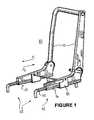
- FIG. 1is a perspective view of a seat frame including continuous seat adjustment apparatus according to the present invention
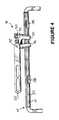
- FIG. 2is an enlarged side perspective view of the continuous seat adjustment apparatus of FIG. 1 with portions of the frame removed;
- FIG. 3is a side perspective view of the continuous seat adjustment apparatus of FIG. 2 with further portions of the frame removed to show internal construction;
- FIG. 4is an enlarged side view of the continuous seat adjustment apparatus of FIG. 3;
- FIG. 5is a perspective view of the continuous seat adjustment apparatus of FIG. 4, portions thereof removed;
- FIG. 6is a greatly enlarged side view of a portion of the continuous seat adjustment apparatus of FIG. 4;
- FIG. 7is a perspective view of the portion of the continuous seat adjustment apparatus of FIG. 6;
- FIG. 8is an exploded view in perspective of the portion of the continuous seat adjustment apparatus of FIG. 7;
- FIG. 9is a further exploded view in perspective of the portion of the continuous seat adjustment apparatus of FIG. 7 .
- FIG. 10is another embodiment of the portion of the continuous seat adjustment apparatus.
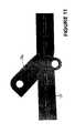
- FIGS. 11-14show views of a jaw actually deforming or denting an inner track upon a large force during a crash.
- FIG. 1illustrates a seat frame 10 of a seat mechanism for use in vehicles or the like.
- Seat frame 10includes a seat back 11 and a seat supporting track assembly 12 .
- Track assembly 12has an inboard portion 13 and an outboard portion 14 .
- Outboard portion 14includes an inner track 15 and an outer track 16 .
- Outer track 16is constructed to be reciprocally movable along inner track 15 by employing continuous seat adjustment mechanism 18 . Reciprocal movement of outer track 16 and the use of adjustment mechanism 18 in combination with track assembly 12 permits continuous adjustment of seat back 11 and outer track 16 along inner track 15 , as will be explained in more detail presently.
- outer track 16includes a housing 19 that ride on and encloses a substantial portion of inner track 15 for relative longitudinal movements therealong.
- a rear portion 20 of housing 19is constructed to have seat back 11 pivotally mounted thereon. The mounting of seat back 11 will not be explained in detail herein since a variety of apparatus and methods can be used.
- a latch mechanismas disclosed in a co-pending patent application entitled ADJUSTABLE SUPPORT APPARATUS AND ARCHITECTURE FOR ADJUSTING SUPPORT APPARATUS, Ser. No. 09/092,675, herein incorporated by reference, is employed.
- Housing 19also includes a transversely enlarged portion 21 enclosing adjustment mechanism 18 , with an adjustment lever 22 positioned on the outside of portion 21 for easy access.
- each of the inner tracks 15 and outer tracks 16(for both inboard portion 13 and outboard portion 14 ) are formed with arcuate shaped longitudinally extending grooves 27 in both of the opposed vertical surfaces.
- Ball bearingsare mounted on carriages 28 , positioned so as to ride in grooves 27 for smooth longitudinal movement of outer tracks 16 along inner tracks 15 .
- Adjustment mechanism 18is affixed to housing 19 by means of a bolt 30 , which in this embodiment is formed to receive a spring locking clip 31 on each end.
- Bolt 30holds housing 19 fixedly engaged with adjustment mechanism 18 for longitudinal movement therewith.
- a connecting rod 32extends between adjustment mechanisms 18 on inboard portion 13 and outboard portion 14 and is engaged with adjustment lever 22 . Connecting rod 32 is mounted to further aid in holding housing 19 fixedly engaged with adjustment mechanism 18 .
- Mechanism 18includes a pair of opposed jaws 35 and 36 having openings 37 and 38 therethrough, respectively, for receiving inner track 15 .
- Jaw 35is pivotally mounted in housing 19 by bolt 30 and jaw 36 is pivotally mounted in housing 19 by connecting rod 32 .
- connecting rod 32is constructed with a generally rectangular (or elliptical) shape.
- an opening 39 through the upper end of jaw 36is formed to mate with connecting rod 32 so as to rotate jaw 36 when connecting rod 32 is rotated by movement of adjustment lever 22 .
- Jaws 35 and 36are mounted in a spaced apart relationship and the lower ends are biased toward each other by means of a tension spring 40 . While a specific spring is illustrated in this embodiment for providing the desired bias, it will be understood by those skilled in the art that a variety of different spring devices could be used. Openings 37 and 38 through jaws 35 and 36 are shaped to allow easy sliding movement of adjustment mechanism 18 along inner track 15 when jaws 35 and 36 are rotated into a substantially parallel orientation by upward rotation of adjustment lever 22 . To this end a mechanical stop 42 is affixed to an inner surface of jaw 36 . As jaw 36 is rotated by upward movement of adjustment lever 22 , stop 42 comes into contact with bolt 30 and limits the relative rotation to a parallel position.
- spring 40biases the lower ends of jaws 35 and 36 together so that inner track 15 is pinched tightly or frictionally engaged in openings 37 and 38 to prevent relative movement between inner track 15 and adjustment mechanism 18 .
- the frictional engagement between either jaw 35 or jaw 36 and inner track 15will increase as forces attempt to move adjustment mechanism 18 (seat frame 10 ) in either direction along inner track 15 .
- a force F 1is applied to seat frame 10 in a forward direction (see FIG. 1 )
- jaw 36will be forced into tighter frictional engagement with inner track 15 to prevent forward longitudinal movement of seat frame 10 .
- a force F 2is applied to seat frame 10 in a rearward direction (see FIG.
- jaw 35will be forced into tighter frictional engagement with inner track 15 to prevent rearward longitudinal movement of seat frame 10 .
- the forces F 1 or F 2can be large enough to cause jaw 36 or jaw 35 to actually deform or dent inner track 15 (see FIGS. 11 through 14 ). In these instances the deformation of inner track 15 further aids in preventing longitudinal movement of seat frame 10 .
- Adjustment mechanism 18can be easily operated to continuously adjust the longitudinal position of a seat anywhere between a maximum and a minimum position so as to achieve an optimum position for each user.
- adjustment mechanism 18is relatively easy and simple to manufacture and assemble.
- the new and improved continuous seat adjustment apparatusis rugged and can withstand vehicle impact shocks, and absorb some of the impact energy while restraining the occupant longitudinally.
Landscapes
- Engineering & Computer Science (AREA)
- Aviation & Aerospace Engineering (AREA)
- Transportation (AREA)
- Mechanical Engineering (AREA)
- Seats For Vehicles (AREA)
Abstract
Description
Claims (14)
Priority Applications (4)
| Application Number | Priority Date | Filing Date | Title |
|---|---|---|---|
| US10/165,144US6736457B2 (en) | 2002-06-07 | 2002-06-07 | Continuous seat adjustment mechanism |
| PCT/US2003/018244WO2003103452A1 (en) | 2002-06-07 | 2003-06-09 | Continuous seat adjustment mechanism |
| AU2003273593AAU2003273593A1 (en) | 2002-06-07 | 2003-06-09 | Continuous seat adjustment mechanism |
| EP03741904AEP1530437A4 (en) | 2002-06-07 | 2003-06-09 | Continuous seat adjustment mechanism |
Applications Claiming Priority (1)
| Application Number | Priority Date | Filing Date | Title |
|---|---|---|---|
| US10/165,144US6736457B2 (en) | 2002-06-07 | 2002-06-07 | Continuous seat adjustment mechanism |
Publications (2)
| Publication Number | Publication Date |
|---|---|
| US20030227207A1 US20030227207A1 (en) | 2003-12-11 |
| US6736457B2true US6736457B2 (en) | 2004-05-18 |
Family
ID=29710372
Family Applications (1)
| Application Number | Title | Priority Date | Filing Date |
|---|---|---|---|
| US10/165,144Expired - Fee RelatedUS6736457B2 (en) | 2002-06-07 | 2002-06-07 | Continuous seat adjustment mechanism |
Country Status (4)
| Country | Link |
|---|---|
| US (1) | US6736457B2 (en) |
| EP (1) | EP1530437A4 (en) |
| AU (1) | AU2003273593A1 (en) |
| WO (1) | WO2003103452A1 (en) |
Cited By (7)
| Publication number | Priority date | Publication date | Assignee | Title |
|---|---|---|---|---|
| US20040245744A1 (en)* | 2003-02-10 | 2004-12-09 | Andrew Emang | Adjustable vehicle |
| WO2007138550A3 (en)* | 2006-05-30 | 2008-03-27 | Leonid Veinberg | Mechanism for infinite step-less linear adjustment based on self-wedging principle |
| US20080231102A1 (en)* | 2007-03-20 | 2008-09-25 | Elio Paul A | Seat track assembly with load pins |
| US20080238124A1 (en)* | 2007-03-26 | 2008-10-02 | Ami Industries, Inc. | Seat track locking mechanism |
| US8534758B2 (en) | 2010-09-13 | 2013-09-17 | Tropitone Furniture Co., Inc. | Reclinable seating apparatus and method |
| US9717340B2 (en) | 2010-09-13 | 2017-08-01 | Tropitone Furniture Co., Inc. | Adjustable seating and furniture |
| US10843605B2 (en) | 2018-05-10 | 2020-11-24 | Dorel Juvenile Group, Inc. | Headrest-height adjuster for juvenile seat |
Families Citing this family (5)
| Publication number | Priority date | Publication date | Assignee | Title |
|---|---|---|---|---|
| FR3124130B1 (en) | 2021-06-21 | 2025-07-11 | Faurecia Sieges Dautomobile | continuously adjustable slide locking system |
| FR3136713B1 (en) | 2022-06-16 | 2024-06-28 | Faurecia Sieges Dautomobile | locking system of a continuously adjustable slide |
| FR3138366A1 (en) | 2022-07-26 | 2024-02-02 | Faurecia Sièges d'Automobile | locking system of a continuously adjustable slide |
| FR3151547B1 (en) | 2023-07-27 | 2025-07-18 | Faurecia Sieges Dautomobile | Continuously adjustable slide locking system |
| FR3160363A1 (en) | 2024-03-21 | 2025-09-26 | Faurecia Sièges d'Automobile | Continuously adjustable slide locking system |
Citations (13)
| Publication number | Priority date | Publication date | Assignee | Title |
|---|---|---|---|---|
| US2292718A (en) | 1939-05-15 | 1942-08-11 | Ryerson & Haynes Inc | Seat adjustment structure |
| US3507472A (en)* | 1967-05-16 | 1970-04-21 | Howell Ind Inc | Seat mounting with telescopically arranged slide means |
| US4154422A (en) | 1976-12-29 | 1979-05-15 | Keiper Automobiltechnik Gmbh & Co Kg | Adjustable and automatically locking motor-vehicle seat mounting assembly |
| US4381096A (en) | 1980-07-30 | 1983-04-26 | Rockwell International Corporation | Seat positioner |
| US4565344A (en) | 1983-12-06 | 1986-01-21 | Tachikawa Spring Co. Ltd. | Seat adjustment device for a vehicle seat |
| US5481941A (en) | 1994-08-19 | 1996-01-09 | Bertrand Faure Ltd. | Infinitely adjustable track locking mechanism |
| US5596910A (en) | 1994-01-05 | 1997-01-28 | C. Rob. Hammerstein Gmbh | Stepless locking device for an adjustable seat of a vehicle |
| US6070938A (en)* | 1998-06-05 | 2000-06-06 | Elio Engineering Inc. | Adjustable support apparatus and architecture for adjusting support apparatus |
| US6086154A (en) | 1998-03-31 | 2000-07-11 | Dura Automotive Systems, Inc. | Infinitely adjustable seat track assembly |
| US6312052B1 (en) | 1999-01-25 | 2001-11-06 | Elio Engineering Inc. | Adjustment mechanism |
| US6318696B1 (en) | 1999-11-08 | 2001-11-20 | Dura Global Technologies | Seat track locking mechanism with infinite adjustment |
| US6334600B1 (en) | 1999-06-07 | 2002-01-01 | Delta Tooling Co., Ltd. | Stepless slide adjuster having a safety lock |
| US6357814B1 (en) | 1997-12-22 | 2002-03-19 | Bertrand Faure Equipements Sa | Vehicle seat assembly comprising a removable seat assembled on guide rails |
Family Cites Families (4)
| Publication number | Priority date | Publication date | Assignee | Title |
|---|---|---|---|---|
| GB1032551A (en)* | 1961-08-25 | 1966-06-08 | Wilmot Breeden Ltd | Improvements in or relating to lockable adjustment means |
| US4387926A (en)* | 1981-06-26 | 1983-06-14 | Rockwell International Corporation | Seat positioner |
| US4441381A (en)* | 1982-09-30 | 1984-04-10 | General Engineering & Manufacturing Corp. | Locking and positioning apparatus for reclining seats |
| US5727847A (en)* | 1996-03-01 | 1998-03-17 | Maple Automotive Innovations, Inc. | Linear actuator |
- 2002
- 2002-06-07USUS10/165,144patent/US6736457B2/ennot_activeExpired - Fee Related
- 2003
- 2003-06-09AUAU2003273593Apatent/AU2003273593A1/ennot_activeAbandoned
- 2003-06-09WOPCT/US2003/018244patent/WO2003103452A1/ennot_activeApplication Discontinuation
- 2003-06-09EPEP03741904Apatent/EP1530437A4/ennot_activeWithdrawn
Patent Citations (13)
| Publication number | Priority date | Publication date | Assignee | Title |
|---|---|---|---|---|
| US2292718A (en) | 1939-05-15 | 1942-08-11 | Ryerson & Haynes Inc | Seat adjustment structure |
| US3507472A (en)* | 1967-05-16 | 1970-04-21 | Howell Ind Inc | Seat mounting with telescopically arranged slide means |
| US4154422A (en) | 1976-12-29 | 1979-05-15 | Keiper Automobiltechnik Gmbh & Co Kg | Adjustable and automatically locking motor-vehicle seat mounting assembly |
| US4381096A (en) | 1980-07-30 | 1983-04-26 | Rockwell International Corporation | Seat positioner |
| US4565344A (en) | 1983-12-06 | 1986-01-21 | Tachikawa Spring Co. Ltd. | Seat adjustment device for a vehicle seat |
| US5596910A (en) | 1994-01-05 | 1997-01-28 | C. Rob. Hammerstein Gmbh | Stepless locking device for an adjustable seat of a vehicle |
| US5481941A (en) | 1994-08-19 | 1996-01-09 | Bertrand Faure Ltd. | Infinitely adjustable track locking mechanism |
| US6357814B1 (en) | 1997-12-22 | 2002-03-19 | Bertrand Faure Equipements Sa | Vehicle seat assembly comprising a removable seat assembled on guide rails |
| US6086154A (en) | 1998-03-31 | 2000-07-11 | Dura Automotive Systems, Inc. | Infinitely adjustable seat track assembly |
| US6070938A (en)* | 1998-06-05 | 2000-06-06 | Elio Engineering Inc. | Adjustable support apparatus and architecture for adjusting support apparatus |
| US6312052B1 (en) | 1999-01-25 | 2001-11-06 | Elio Engineering Inc. | Adjustment mechanism |
| US6334600B1 (en) | 1999-06-07 | 2002-01-01 | Delta Tooling Co., Ltd. | Stepless slide adjuster having a safety lock |
| US6318696B1 (en) | 1999-11-08 | 2001-11-20 | Dura Global Technologies | Seat track locking mechanism with infinite adjustment |
Cited By (12)
| Publication number | Priority date | Publication date | Assignee | Title |
|---|---|---|---|---|
| US20040245744A1 (en)* | 2003-02-10 | 2004-12-09 | Andrew Emang | Adjustable vehicle |
| WO2007138550A3 (en)* | 2006-05-30 | 2008-03-27 | Leonid Veinberg | Mechanism for infinite step-less linear adjustment based on self-wedging principle |
| US20080231102A1 (en)* | 2007-03-20 | 2008-09-25 | Elio Paul A | Seat track assembly with load pins |
| US20080238124A1 (en)* | 2007-03-26 | 2008-10-02 | Ami Industries, Inc. | Seat track locking mechanism |
| US7887020B2 (en) | 2007-03-26 | 2011-02-15 | Ami Industries, Inc. | Seat track locking mechanism |
| US8534758B2 (en) | 2010-09-13 | 2013-09-17 | Tropitone Furniture Co., Inc. | Reclinable seating apparatus and method |
| US8690247B2 (en) | 2010-09-13 | 2014-04-08 | Tropitone Furniture Co., Inc. | Reclinable seating apparatus and method |
| US9084488B2 (en) | 2010-09-13 | 2015-07-21 | Tropitone Furniture Co., Inc. | Reclinable seating apparatus and method |
| US9226581B2 (en) | 2010-09-13 | 2016-01-05 | Tropitone Furniture Co., Inc. | Reclinable seating apparatus and method |
| US9717340B2 (en) | 2010-09-13 | 2017-08-01 | Tropitone Furniture Co., Inc. | Adjustable seating and furniture |
| US9743772B2 (en) | 2010-09-13 | 2017-08-29 | Tropitone Furniture Co., Inc. | Adjustable seating and furniture |
| US10843605B2 (en) | 2018-05-10 | 2020-11-24 | Dorel Juvenile Group, Inc. | Headrest-height adjuster for juvenile seat |
Also Published As
| Publication number | Publication date |
|---|---|
| AU2003273593A1 (en) | 2003-12-22 |
| EP1530437A4 (en) | 2009-11-25 |
| US20030227207A1 (en) | 2003-12-11 |
| WO2003103452A1 (en) | 2003-12-18 |
| EP1530437A1 (en) | 2005-05-18 |
Similar Documents
| Publication | Publication Date | Title |
|---|---|---|
| US10500987B2 (en) | Seat-track assembly | |
| US6736457B2 (en) | Continuous seat adjustment mechanism | |
| EP2768696B1 (en) | Seat-track assembly | |
| KR100512889B1 (en) | Locking device of seat-track for vehicles | |
| KR960012613B1 (en) | Infant safety seats for cars | |
| US7191995B2 (en) | Seat slide mechanism for vehicles | |
| EP2206624B1 (en) | Seat apparatus for vehicle | |
| US4068887A (en) | Seat mountings | |
| US7665704B2 (en) | Seat rail apparatus | |
| EP1757484A3 (en) | Child car seat | |
| GB2138670A (en) | Seat belt anchor assembly | |
| JP2609425B2 (en) | Rotatable seat belt buckle mounting bracket for automotive seat adjuster | |
| EP0791500A2 (en) | Infant seat for vehicles | |
| US7497474B2 (en) | Cross-car adjustable strap buckle | |
| JP2838103B2 (en) | Car seat adjuster | |
| WO2002029271A2 (en) | Cone recliner/clutch mechanism | |
| US5083735A (en) | Vehicle seat | |
| US6805394B2 (en) | Locking mechanism for a seat frame | |
| KR200494121Y1 (en) | Three point safety belt converting apparatus | |
| JPH068761A (en) | Seat structure | |
| KR0117125Y1 (en) | Headrest height control device of a car | |
| KR200324044Y1 (en) | Locking device of seat-track for vehicles | |
| JPS6231314Y2 (en) | ||
| JPH064743Y2 (en) | Seat structure with reclining device | |
| US20240336172A1 (en) | Shoulder strap retainer for car seat |
Legal Events
| Date | Code | Title | Description |
|---|---|---|---|
| AS | Assignment | Owner name:ELIO ENGINEERING, INC., ARIZONA Free format text:ASSIGNMENT OF ASSIGNORS INTEREST;ASSIGNORS:ELIO, PAUL;SANKARANARAYANAN, HARIHARAN K.;GLASPIE, ROBERT E.;REEL/FRAME:012993/0581 Effective date:20020531 | |
| FEPP | Fee payment procedure | Free format text:PAT HOLDER NO LONGER CLAIMS SMALL ENTITY STATUS, ENTITY STATUS SET TO UNDISCOUNTED (ORIGINAL EVENT CODE: STOL); ENTITY STATUS OF PATENT OWNER: LARGE ENTITY | |
| REFU | Refund | Free format text:REFUND - SURCHARGE, PETITION TO ACCEPT PYMT AFTER EXP, UNINTENTIONAL (ORIGINAL EVENT CODE: R2551); ENTITY STATUS OF PATENT OWNER: LARGE ENTITY | |
| FPAY | Fee payment | Year of fee payment:4 | |
| AS | Assignment | Owner name:ESG - ACCURIDE, LLC., ARIZONA Free format text:ASSIGNMENT OF ASSIGNORS INTEREST;ASSIGNOR:ELIO ENGINEERING, INC.;REEL/FRAME:019690/0307 Effective date:20061229 | |
| AS | Assignment | Owner name:ELIO ENGINEERING, INC., DBA ESG ENGINEERING, ARIZO Free format text:ASSIGNMENT OF ASSIGNORS INTEREST;ASSIGNOR:ESG - ACCURIDE, LLC;REEL/FRAME:025768/0304 Effective date:20110124 Owner name:ACCURIDE CORPORATION, INDIANA Free format text:SECURITY AGREEMENT;ASSIGNOR:ELIO ENGINEERING, INC., DBA ESG ENGINEERING;REEL/FRAME:025765/0603 Effective date:20110124 | |
| REMI | Maintenance fee reminder mailed | ||
| FPAY | Fee payment | Year of fee payment:8 | |
| SULP | Surcharge for late payment | Year of fee payment:7 | |
| REMI | Maintenance fee reminder mailed | ||
| LAPS | Lapse for failure to pay maintenance fees | ||
| STCH | Information on status: patent discontinuation | Free format text:PATENT EXPIRED DUE TO NONPAYMENT OF MAINTENANCE FEES UNDER 37 CFR 1.362 | |
| FP | Lapsed due to failure to pay maintenance fee | Effective date:20160518 |