US6735811B2 - Cleaning liquid dispensing system for a hard floor surface cleaner - Google Patents
Cleaning liquid dispensing system for a hard floor surface cleanerDownload PDFInfo
- Publication number
- US6735811B2 US6735811B2US10/143,582US14358202AUS6735811B2US 6735811 B2US6735811 B2US 6735811B2US 14358202 AUS14358202 AUS 14358202AUS 6735811 B2US6735811 B2US 6735811B2
- Authority
- US
- United States
- Prior art keywords
- cleaning liquid
- cleaner
- flow
- cleaning
- floor surface
- Prior art date
- Legal status (The legal status is an assumption and is not a legal conclusion. Google has not performed a legal analysis and makes no representation as to the accuracy of the status listed.)
- Expired - Lifetime
Links
Images


Classifications
- A—HUMAN NECESSITIES
- A47—FURNITURE; DOMESTIC ARTICLES OR APPLIANCES; COFFEE MILLS; SPICE MILLS; SUCTION CLEANERS IN GENERAL
- A47L—DOMESTIC WASHING OR CLEANING; SUCTION CLEANERS IN GENERAL
- A47L11/00—Machines for cleaning floors, carpets, furniture, walls, or wall coverings
- A47L11/29—Floor-scrubbing machines characterised by means for taking-up dirty liquid
- A47L11/30—Floor-scrubbing machines characterised by means for taking-up dirty liquid by suction
- A—HUMAN NECESSITIES
- A47—FURNITURE; DOMESTIC ARTICLES OR APPLIANCES; COFFEE MILLS; SPICE MILLS; SUCTION CLEANERS IN GENERAL
- A47L—DOMESTIC WASHING OR CLEANING; SUCTION CLEANERS IN GENERAL
- A47L11/00—Machines for cleaning floors, carpets, furniture, walls, or wall coverings
- A47L11/02—Floor surfacing or polishing machines
- A47L11/03—Floor surfacing or polishing machines characterised by having provisions for supplying cleaning or polishing agents
- A—HUMAN NECESSITIES
- A47—FURNITURE; DOMESTIC ARTICLES OR APPLIANCES; COFFEE MILLS; SPICE MILLS; SUCTION CLEANERS IN GENERAL
- A47L—DOMESTIC WASHING OR CLEANING; SUCTION CLEANERS IN GENERAL
- A47L11/00—Machines for cleaning floors, carpets, furniture, walls, or wall coverings
- A47L11/29—Floor-scrubbing machines characterised by means for taking-up dirty liquid
- A—HUMAN NECESSITIES
- A47—FURNITURE; DOMESTIC ARTICLES OR APPLIANCES; COFFEE MILLS; SPICE MILLS; SUCTION CLEANERS IN GENERAL
- A47L—DOMESTIC WASHING OR CLEANING; SUCTION CLEANERS IN GENERAL
- A47L11/00—Machines for cleaning floors, carpets, furniture, walls, or wall coverings
- A47L11/40—Parts or details of machines not provided for in groups A47L11/02 - A47L11/38, or not restricted to one of these groups, e.g. handles, arrangements of switches, skirts, buffers, levers
- A47L11/4011—Regulation of the cleaning machine by electric means; Control systems and remote control systems therefor
- A—HUMAN NECESSITIES
- A47—FURNITURE; DOMESTIC ARTICLES OR APPLIANCES; COFFEE MILLS; SPICE MILLS; SUCTION CLEANERS IN GENERAL
- A47L—DOMESTIC WASHING OR CLEANING; SUCTION CLEANERS IN GENERAL
- A47L11/00—Machines for cleaning floors, carpets, furniture, walls, or wall coverings
- A47L11/40—Parts or details of machines not provided for in groups A47L11/02 - A47L11/38, or not restricted to one of these groups, e.g. handles, arrangements of switches, skirts, buffers, levers
- A47L11/4013—Contaminants collecting devices, i.e. hoppers, tanks or the like
- A47L11/4016—Contaminants collecting devices, i.e. hoppers, tanks or the like specially adapted for collecting fluids
- A—HUMAN NECESSITIES
- A47—FURNITURE; DOMESTIC ARTICLES OR APPLIANCES; COFFEE MILLS; SPICE MILLS; SUCTION CLEANERS IN GENERAL
- A47L—DOMESTIC WASHING OR CLEANING; SUCTION CLEANERS IN GENERAL
- A47L11/00—Machines for cleaning floors, carpets, furniture, walls, or wall coverings
- A47L11/40—Parts or details of machines not provided for in groups A47L11/02 - A47L11/38, or not restricted to one of these groups, e.g. handles, arrangements of switches, skirts, buffers, levers
- A47L11/4036—Parts or details of the surface treating tools
- A47L11/4038—Disk shaped surface treating tools
- A—HUMAN NECESSITIES
- A47—FURNITURE; DOMESTIC ARTICLES OR APPLIANCES; COFFEE MILLS; SPICE MILLS; SUCTION CLEANERS IN GENERAL
- A47L—DOMESTIC WASHING OR CLEANING; SUCTION CLEANERS IN GENERAL
- A47L11/00—Machines for cleaning floors, carpets, furniture, walls, or wall coverings
- A47L11/40—Parts or details of machines not provided for in groups A47L11/02 - A47L11/38, or not restricted to one of these groups, e.g. handles, arrangements of switches, skirts, buffers, levers
- A47L11/4036—Parts or details of the surface treating tools
- A47L11/4044—Vacuuming or pick-up tools; Squeegees
- A—HUMAN NECESSITIES
- A47—FURNITURE; DOMESTIC ARTICLES OR APPLIANCES; COFFEE MILLS; SPICE MILLS; SUCTION CLEANERS IN GENERAL
- A47L—DOMESTIC WASHING OR CLEANING; SUCTION CLEANERS IN GENERAL
- A47L11/00—Machines for cleaning floors, carpets, furniture, walls, or wall coverings
- A47L11/40—Parts or details of machines not provided for in groups A47L11/02 - A47L11/38, or not restricted to one of these groups, e.g. handles, arrangements of switches, skirts, buffers, levers
- A47L11/408—Means for supplying cleaning or surface treating agents
- A47L11/4083—Liquid supply reservoirs; Preparation of the agents, e.g. mixing devices
- A—HUMAN NECESSITIES
- A47—FURNITURE; DOMESTIC ARTICLES OR APPLIANCES; COFFEE MILLS; SPICE MILLS; SUCTION CLEANERS IN GENERAL
- A47L—DOMESTIC WASHING OR CLEANING; SUCTION CLEANERS IN GENERAL
- A47L11/00—Machines for cleaning floors, carpets, furniture, walls, or wall coverings
- A47L11/40—Parts or details of machines not provided for in groups A47L11/02 - A47L11/38, or not restricted to one of these groups, e.g. handles, arrangements of switches, skirts, buffers, levers
- A47L11/408—Means for supplying cleaning or surface treating agents
- A47L11/4088—Supply pumps; Spraying devices; Supply conduits
- B—PERFORMING OPERATIONS; TRANSPORTING
- B01—PHYSICAL OR CHEMICAL PROCESSES OR APPARATUS IN GENERAL
- B01F—MIXING, e.g. DISSOLVING, EMULSIFYING OR DISPERSING
- B01F23/00—Mixing according to the phases to be mixed, e.g. dispersing or emulsifying
- B01F23/20—Mixing gases with liquids
- B01F23/29—Mixing systems, i.e. flow charts or diagrams
- B01F23/291—Mixing systems, i.e. flow charts or diagrams for obtaining foams or aerosols
- B—PERFORMING OPERATIONS; TRANSPORTING
- B01—PHYSICAL OR CHEMICAL PROCESSES OR APPARATUS IN GENERAL
- B01J—CHEMICAL OR PHYSICAL PROCESSES, e.g. CATALYSIS OR COLLOID CHEMISTRY; THEIR RELEVANT APPARATUS
- B01J13/00—Colloid chemistry, e.g. the production of colloidal materials or their solutions, not otherwise provided for; Making microcapsules or microballoons
- B01J13/0095—Preparation of aerosols
Definitions
- the present inventionrelates generally to mobile hard floor surface cleaners and, more particularly, to a controlled cleaning liquid dispensing system for use in a hard floor surface cleaner.
- Hard floor surface cleanersare widely used to clean the floors of industrial and commercial buildings. They range in size from a small model that is controlled by an operator walking behind and may clean a path ranging from 15 inches to 36 inches wide, to a large model that is controlled by an operator riding on the machine and can clean a path as wide as 5 feet.
- These hard floor cleanersinclude motorized drive wheels, a solution tank to hold a cleaning solution and a recovery tank to hold soiled cleaning solution recovered from the floor being scrubbed.
- the cleaning solution from the solution tankis applied to the hard floor surface adjacent a scrub head.
- the scrub headgenerally contains one or more motorized scrubbing brushes attached either in front of, under, or behind the vehicle. These scrubbing brushes typically rotate to provide the desired scrubbing action.
- the soiled cleaning solutionis then recovered using a solution recovery system, which returns the soiled cleaning solution to the recovery tank.
- the cleaning solutionis typically gravity fed to the scrub head at a rate that varies in response to the volume of cleaning solution contained in the solution tank. As the volume of cleaning solution contained in the solution tank decreases, the rate at which the cleaning solution is fed to the scrub head decreases.
- a typical hard floor cleaner having a 32 inch wide scrubbing swathapplies the cleaning solution to the hard floor surface at a rate that varies from between approximately 1.0 gallons per minute (GPM) when the solution tank is full to a rate of 0.5 GPM when the tank contains a low volume of cleaning solution.
- GPMgallons per minute
- the high volume flow rate of cleaning solutionis generally desired to provide complete wetting of the floor being cleaned.
- the lack of control of the volume flow rate of the cleaning solutionresults in an excessive amount of cleaning solution being distributed to the floor, when, for example, the solution tank is full.
- the high volume flow rate of the cleaning solution of prior art hard floor surface cleanersalso results in extended downtime.
- the long downtime periodsare generally due to the numerous disposals of soiled cleaning solution and refills of cleaning solution that must be performed for a given job.
- the disposal of the soiled cleaning solutionmay require special handling and/or additional costs to ensure that it is disposed of properly.
- the large volumes of cleaning solution that are used by prior art hard floor surface cleanersreduce the efficiency at which a cleaning job can be performed.
- the present inventionis directed to a cleaning liquid dispensing system for use in a mobile hard floor surface cleaner that provides a substantially constant flow of cleaning liquid that can be provided to the scrubbing components of the cleaner. This results in more efficient use of the cleaning liquid, longer operational runtimes and shorter downtime.
- the cleaning liquid dispensing systemincludes fluid conduit in fluid communication with a supply of cleaning liquid, a pump, and a flow restriction member.
- the pumpis adapted to drive a flow of the cleaning liquid through the conduit.
- the flow restriction membergenerates a pressure drop in the conduit, thereby restricting the flow of the cleaning liquid therethrough.
- FIGS. 1 and 2are simplified side elevation views of hard floor surface cleaners in accordance with various embodiments of the present invention.
- FIG. 3is a schematic diagram illustrating a cleaning liquid dispensing system in accordance with embodiments of the invention.
- FIG. 4is a front elevation view of a cleaning liquid dispensing system in accordance with an embodiment of the invention.
- FIG. 5is a schematic diagram of a flow restriction member in accordance with an embodiment of the invention.
- FIG. 6is a front elevation view of a hard floor surface cleaner in accordance with embodiments of the invention.
- FIG. 7is a detailed front elevation view of a cleaning liquid aeration system in accordance with an embodiment of the invention.
- FIG. 8is a front elevation view of the hard floor surface cleaner in accordance with embodiments of the invention.
- FIG. 9is a detailed front elevation view of a portion of a scrub head in accordance with an embodiment of the invention.
- FIG. 10is a cross-sectional view of a recovery system in accordance with various embodiments of the invention.
- FIG. 11is a front elevation view of a hard floor surface cleaner in accordance with an embodiment of the invention.
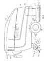
- FIG. 1illustrates a hard floor surface cleaner 10 in which embodiments of the present invention can be used.
- the illustrated cleaner 10is a walk-behind cleaner used to clean hard floor surfaces, such as concrete, tile, vinyl, terrazzo, etc.
- cleaner 10can be a ride-on or towed-behind cleaner performing a scrubbing operation as described herein.
- Cleaner 10may include electrical motors powered through an on-board power source, such as batteries, or through an electrical cord. Alternatively, an internal combustion engine system could be used either alone, or in combination with, the electric motors.
- Cleaner 10generally includes a recovery tank 12 and a lid 14 .
- Lid 14is attached along one side of the recovery tank 12 by hinges (not shown) so that lid 14 can be pivoted up to provide access to the interior of tank 12 .
- Cleaner 10also includes a tank 18 for containing cleaning liquid or a primary cleaning liquid component that is applied to the hard floor surface during cleaning operations.
- a scrub head 20includes a scrubbing member 22 , shrouds 24 , and a scrubbing member drive 26 .
- Scrubbing member 22may be one or more brushes, such as bristle brushes, pad scrubbers, or other hard floor surface scrubbing elements.
- Drive 26includes one or more electric motors to rotate the scrubbing member 22 .
- Scrubbing member 22may be a disc-type scrub brush rotating about a generally vertical axis of rotation relative to the hard floor surface.
- scrubbing member 22may be a cylindrical-type scrub brush rotating about a generally horizontal axis of rotation relative to the hard floor surface.
- Drive 26may also oscillate scrubbing member 22 .
- Scrub head 20is attached to cleaner 10 such that scrub head 20 can be moved between a lowered cleaning position and a raised travelling position.
- a machine frame 27supports recovery tank 12 on wheels 28 and castors 29 . Details of the frame are shown and described in U.S. Pat. No. 5,611,105, the disclosure of which is incorporated herein by reference. Wheels 28 are preferably driven by a motor and transaxle assembly shown schematically at 30 .
- the rear of the framecarries a linkage 31 to which a fluid recovery device 32 is attached.
- the fluid recovery device 32includes a vacuum squeegee 34 and vacuum communication with an inlet chamber in recovery tank 12 through a hose 36 .
- the bottom of the inlet chamberis provided with a drain 40 with a drain hose 42 connected to it.
- FIG. 2illustrates hard floor surface cleaner 10 utilizing an alternative soiled solution recovery device 32 .
- the soiled solution recovery device 32includes a non-vacuumized mechanical device for lifting the soiled solution away from the floor surface and conveying the soiled solution toward a collection tank or receptacle 44 .
- the non-vacuumized mechanical deviceincludes a plurality of wiping medium such as pliable material elements 46 which are rotated into contact with the floor surface to engage and lift the soiled solution from the floor surface.
- the pliable material elements 46may be of an absorbent material.
- the pliable material elements 46convey the solution to the collection receptacle 44 .
- Solution captured on the pliable elements 46may be removed via a mechanical action, such as through a shearing device or a squeezing device.
- the mechanical action used to remove soiled solution from the pliable material elements 46is a scraper bar 48 which engages the pliable material elements 46 to release the soiled solution.
- Alternative mechanical devices, structures, or systemsmay be used to convey the soiled solution from the floor surface toward a collection receptacle.
- Cleaner 10can include a battery compartment 50 in which batteries 52 reside as shown in FIG. 1 . Batteries 52 provide power to drive motors 26 , vacuum fan 54 , and other electrical components of cleaner 10 . Vacuum fan 54 is mounted in the lid 14 . A control unit 56 mounted on the rear of the body of cleaner 10 includes steering control handles 58 and operating controls and gages for cleaner 10 . Additional aspects of automatic hard floor surface cleaners are disclosed in U.S. Pat. Nos. 5,483,718; 5,515,568; and 5,566,422, each of which are incorporated herein by reference.
- the present inventionis directed to a cleaning liquid dispensing system 60 for use in a hard floor surface cleaner, such as cleaner 10 , that can provide a near constant flow of cleaning liquid to scrub head 20 or other cleaner component.
- the cleaning liquid dispensing system 60generally includes fluid conduit 62 and fluid communication with a supply of cleaning liquid 64 , a pump 66 , and a flow restriction member 68 , as shown in the schematic diagram of FIG. 3 and in the front elevation view in FIG. 4 .
- Pump 66is configured to drive a flow of cleaning liquid from supply 64 through conduit 62 .
- Flow restriction member 68is configured to generate a pressure drop in conduit 62 to thereby restrict the flow of cleaning liquid therethrough.
- a controlled output flow 70 of cleaning liquidthat can be provided to a cleaning liquid distributor 71 that directs the flow of cleaning liquid to a hard floor surface, or other cleaner component.
- a solenoid actuated on/off valve 72can be installed to open and close the fluid flow path of conduit 62 .
- the output flow 70is preferably maintained at a substantially constant low volume flow rate that is desired for the cleaning operation.
- This near constant low flow rate of the output flow 70 of cleaning liquidprovides significant improvements over the prior art gravity-fed fluid dispensing systems.
- the prior art cleaners that have a varying flow rate of cleaning liquidmust be configured to ensure that the minimum flow rate of cleaning liquid meets a desired flow rate of cleaning liquid that is necessary to perform the cleaning operation. Unfortunately, this results in much higher flow rates and, possibly, much lower flow rates then designed.
- the cleaning liquid dispensing system 60 of the present inventionmaintains a constant flow rate in accordance with what is desired for the cleaning operation.
- the prior art cleanerwhen the required flow rate of cleaning liquid is 0.5 GPM, the prior art cleaner will have a flow rate that varies from substantially greater than 0.5 GPM down to 0.5 GPM, whereas the cleaning liquid dispensing system 60 of the present invention provides a constant flow of 0.5 GPM or less as desired.
- the output flow 70is preferably limited by flow restriction member 68 to approximately 0.2 GPM. This leads to longer operational runtimes shorter downtime, and faster floor cleaning operations. Furthermore, cleaning liquid expenses are also reduced since less is used for a given job. Also, this reduction in cleaning liquid reduces time spent disposing liquid waste and refilling the cleaner with cleaning liquid. Other advantages, such as faster floor drying, can also be realized by hard floor surface cleaners utilizing cleaning liquid dispensing system 60 of the present invention, further improving the efficiency of floor cleaning operations.
- cleaning liquid 64is a mixture of a primary cleaning component and a cleaning chemical or agent, which can be stored, for example in tank 18 , shown in FIG. 2 .
- the primary cleaning componentis preferably water.
- the cleaning agentpreferably includes an anionic surfactant, a non-anionic surfactant, a cationic surfactant, or a combination thereof.
- a particularly preferred surfactantis DeTeric CP-Na-38 manufactured by DeForest Enterprises, Inc. of Boca Raton, Fla.
- a particularly preferred surfactant concentration of the cleaning liquidis approximately 0.1% of the primary cleaning liquid component.
- Alternative cleaning liquidsmay include one or more surfactants, builders, solvents, or other components.
- the supply of cleaning liquidis formed as a combination of separate supplies of cleaning agent 74 and the primary cleaning liquid component 76 as indicated schematically in FIG. 3 .
- the cleaning agentis preferably provided in concentrated form from supply 74 , which could be a disposable cartridge.
- the supply of cleaning agent 74is fluidically coupled to a chemical dispenser 77 , which provides a predetermined volume flow rate, preferably 0.1% of the primary cleaning component, of cleaning agent to a fluid mixing member 78 .
- the supply of primary cleaning liquid component 76could be stored, for example, in tank 18 , and is fluidically coupled to fluid mixing member 78 .
- Fluid mixing member 78combines the cleaning agent from chemical dispenser 77 and the primary cleaning liquid component to form the cleaning liquid 64 .
- cleaning liquid dispensing system 60can be positioned to control the flow of the primary cleaning liquid component, as indicated by dashed box 60 ′ of FIG. 3 . It should be understood that multiple cleaning liquid dispensing systems 60 can be employed to provide the desired fluid flow control in cleaner 10 .
- Pump 66is generally positioned in line with fluid conduit 62 and includes an outlet 80 , shown in FIG. 4, that is maintained at a high pressure
- the output flow 70 of cleaning liquidis provided through outlet 80 and through conduit 62 .
- the pressure at outlet 80is held substantially constant at approximately 40 pounds per square inch (psi).
- pump 66is a diaphragm pump, such as diaphragm pump model number 8006-543-250 manufactured by Shur Flo of Garden Grove, Calif.
- Flow restriction member 68is generally positioned in line with conduit 62 and the flow of cleaning liquid.
- Flow restriction member 68includes an upstream high pressure side 82 and a downstream low pressure side 84 as shown in FIG. 4 .
- the pressure drop across flow restriction member 68 between high pressure side 82 and low pressure side 84restricts the flow rate of the cleaning liquid through conduit 62 to provide the desired output flow 70 .
- Multiple flow restriction members 68can be employed to provide the desired pressure drop in conduit 62 and volume flow rate of flow 70 .
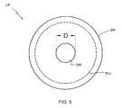
- flow restriction member 68is a metering orifice or orifice plate 86 , shown schematically in FIG. 5 .
- Orifice plate 86includes an orifice 88 through which the output flow 70 of cleaning liquid flows.
- Plate 86is installed in conduit 62 , the inner diameter of which is indicated by dashed line 90 , such that output flow 70 of cleaning liquid is forced to flow through orifice 88 . This produces the pressure drop as described above and restricts the output flow 70 to the desired flow rate.
- orifice 88 of orifice plate 86has a diameter D of approximately 0.03 inch to provide the desired output flow of 0.2 GPM when the pressure of outlet 80 of pump 66 is at 40 psi.
- a suitable metering orifice or orifice plate 86is part number CP 4916-40 manufactured by Spraying Systems Co. of Wheaton, Ill.
- Other orifice plates or metering orifice configurationsare possible as well, such as by providing multiple orifices in the plate 86 or other flow restriction configurations.
- the pressure at output 80can be varied depending upon the velocity of cleaner 10 .
- the pressure at outlet 80can be reduced to lower the output flow 70 of cleaning liquid and, thus, the volume of cleaning liquid that is applied to the hard floor surface.
- the pressure at outlet 80can be increased to increase the output flow of cleaning liquid 70 to maintain the desired distribution of cleaning liquid to the hard floor surface.
- the cleaning liquidcan be aerated to create a foam-like aerated cleaning liquid that is delivered to the hard floor surface and utilized in the scrubbing process.
- the foam-like aerated cleaning liquidfacilitates an efficient wetting of the floor surface.
- the preferred surfactant mentioned abovecan be used without additional additives to provide the desired foaming of the cleaning liquid.
- the cleaning operation of this embodiment of the inventioninvolves aerating the cleaning liquid into a foam-like aerated cleaning liquid (foamed cleaning liquid), applying the foamed cleaning liquid to the hard floor surface, working the foamed cleaning liquid with the scrub head 20 , and substantially de-aerating the foamed cleaning liquid prior to recovering the soiled cleaning liquid with the recovery system.
- de-aeration of the aerated cleaning liquidis rapidly achieved during contact with scrubbing member 22 . As a result, relatively little foam is transferred into the recovery tank 12 by the recovery system.
- a cleaning liquid aerator for generating the foamed cleaning liquid for application to the hard floor surface during a scrubbing processis generally indicated at 90 .
- Aerator 90may include a variety of foam generation devices, including but not limited to, pressurized air and/or pressurized liquid systems, agitation systems, etc.
- aerator 90is disposed on the housing above scrubbing head 20 and includes an air system 92 for pressurizing air that is mixed with the flow 70 of cleaning liquid from dispensing system 60 in a first fluid mixing member 96 . The mixed air and cleaning liquid can then be provided to a second fluid mixing member 98 for further mixing.
- a fluid distributor 71directs the foamed aerated cleaning liquid generated by the mixing members 96 and 98 to the hard floor surface or other component of cleaner 10 .
- the volume flow rate of the foamed aerated cleaning liquid delivered through fluid distributor 71is substantially controlled by the volume flow rate of flow 70 of cleaning liquid and, thus, the cleaning liquid dispensing system 60 .
- the air system 92 for generating and conveying pressurized airincludes an air pump 100 , a check valve 102 , and associated fluid conduit sections 104 and 108 .
- Suitable types of air pumps 100include piston, diaphragm or rotary vane pumps.
- One preferred air pump 100is a piston pump model number 22D1180-206-1002 manufactured by Gast Manufacturing, Inc., of Benton Harbor, Mich.
- Check valve 102is provided for back flow prevention of cleaning liquid into the air pump 100 .
- Check valvescan also be positioned in line with dispersing system 60 to prevent the back flow of fluid therethrough.
- the pressure at the output of air pump 100is greater than that at low pressure side 84 of flow restriction member 68 , such as approximately 40 psi.
- the first mixing element 96receives pressurized air from the air pump 100 via conduit section 108 and pressurized cleaning solution from cleaning liquid dispensing system 60 via conduit section 110 .
- the first mixing element 96(Y-coupling), has a pair of inlet ports 112 and 114 and an outlet port 116 through which the mixture is discharged.
- First mixing element 96may be alternatively configured, but should include at least a pair of inlet ports for pressurized air and pressurized cleaning liquid and an outlet port for discharging the mixture.
- First mixing element 96may be defined as a passive mixing element.
- An alternative first mixing elementmay include active mixing devices, such as energized impeller.
- valve 72controls the flow of mixture to the second mixing element 98 via conduit section 120 .
- valve 72is operable between an open position in which solution is permitted to flow out of the first mixing element 96 and a closed position in which solution flow is blocked.
- Alternative valvesmay be used to control the flow of fluid within the system, such as a variable output valve or other suitable component
- the second mixing element 98receives and further mixes the pressurized air and cleaning liquid from the first mixing element 96 .
- Second mixing element 98can be a passive element including a relatively rigid receiver 122 having an inlet port 124 and an outlet port 126 .
- a diffusion medium 128is contained within the receiver 122 .
- the diffusion medium 108is capable of producing foam by shearing action, air entrainment or a combination of both.
- the diffusion medium 128includes a plurality of SCOTCH-BRITE brand copper pads, manufactured by Minnesota Mining and Manufacturing Company of St. Paul, Minn.
- Alternative diffusion mediamay also be practicable, including but not limited to glass beads, foams, and other porous substrates.
- the length and diameter of the receiver 122 as well as structure of the diffusion medium 128are sized so as to maintain the operating pressure of the foaming system 90 at a desired level.
- the diffusion medium 128 and receiver 122 sizeaffect the quality of the foam generated in the second mixing element 98 . More particularly, using coarser diffusion medium 128 allows for easier passage of the foam through the receiver 122 since there are fewer contact, or blocking, points between medium 128 in the receiver 122 . However, the coarser diffusion medium also results in larger foam bubbles. By using a sufficiently long receiver 122 with an appropriate diffusion medium 128 , large foam bubbles formed near the upstream end of the receiver 122 will break down into more desirable smaller bubbles prior to reaching the downstream end of the receiver 122 . As an example, the receiver 122 of the illustrated embodiment is about 9 inches long and has an inner diameter of approximately 2 inches.
- the receiver 122may be provided at an incline relative to the ground surface so that inlet port 124 is at a slightly lower elevation than outlet port 126 . By so providing the inlet port 124 above the outlet port, the amount of aerated cleaning liquid delivered to the scrub brushes 22 after the solenoid valve 72 has closed may be minimized.
- Various modifications and adaptations to the aerator 90may be practicable.
- the foamed cleaning liquidis discharged from the second mixing element 98 and directed toward the fluid distributor 71 via conduit section 130 .
- Flow within conduit 130is separated by a T-coupling 132 into conduits 134 and 136 of fluid distributor 71 .
- the outlet of conduit sections 134 and 136are provided above associated scrubbing member 22 .
- flow from conduits 134 and 136exits near the center of the scrubbing members 22 to deliver cleaning fluid into an annular trough 138 in the pad driver hub 140 .
- a series of holes 142 in the bottom of trough 122 138pass the foamed cleaning liquid down to the central region of the scrubbing member 22 .
- the foamed cleaning liquid(or non-foamed cleaning liquid) is centrifuged out under the scrubbing member 22 in contact with the hard floor surface.
- Alternative approaches to aerated cleaning liquid deliverywould be appreciated by those skilled in the relevant arts.
- a foam control switch 144shown in FIG. 1, is electrically connected to the air compressor 92 , cleaning liquid pump 66 , and solenoid valve 72 for controlling operation of the aerator system 90 .
- the foam control switch 144may include a manual switch mounted on the control panel.
- Hard floor surface cleaner 10generates a relatively wet foam as compared to carpet cleaners to provide the desired wetting of the hard floor surface.
- a foam's “dryness”may be defined in relation to this volumetric expansion ratio.
- a “dry” foamhas a higher expansion ratio as compared to a “wet” foam.
- High-expansion foams used in presently available types of carpet cleaning machinesare actually relatively “dry” as the ratio of air to water is high. Dry foams are used in carpet cleaning to facilitate quick drying of the cleaned carpet.
- a “wet” foamis not typically used in carpet cleaning devices as these foams can cause excessive wetting of the carpet which may lead long drying times and mold development.
- the ratio of volumes between the cleaning liquid (non-aerated) and the foamed cleaning liquidis approximately 1:8.
- 0.15 gallons of cleaning liquidis aerated to occupy 1.25 gallons.
- Other volume ratioswould yield acceptable scrubbing results.
- the foamed cleaning liquidis dispensed by fluid distributor 71 through conduit sections 134 and 136 at the front of the chassis and the scrubbing media 22 engage the foamed cleaning liquid and hard floor surface.
- the foamed cleaning liquidpermits an efficient wetting of the hard floor surface, even at dramatically reduced cleaning liquid flow rates (e.g. 0.26 GPM).
- the process of mechanically working the foam with the scrubbing medium 22results in substantial defoaming or de-aeration (up to 95% reduction in volume) of the foamed cleaning liquid prior to soiled solution recovery.
- prior art devices using known chemical detergentsmay create additional foam by the brush action, necessitating defoaming devices as mentioned herein.
- a soiled solution of cleaning liquid and soilis developed by the interaction of the scrubbing medium 22 in contact with the foamed cleaning liquid and the hard floor surface.
- the soiled solutionincludes partially de-aerated cleaning liquid and soil released from the hard floor surface.
- the soiled solutionis recovered from the hard floor surface by recovery system 32 and conveyed to recovery tank 12 .
- the recovered soiled solutionmay be treated to reduce foam using various defoaming techniques, including an addition of defoaming chemical to the recovery tank 12 .
- the soiled solutionis substantially defoamed during the scrubbing process.
- the above referenced particular surfactantbeneficially yields a foamed cleaning solution which rapidly de-aerates after contact with the rotating scrub brushes 22 . As a result, in a preferred embodiment no additional defoaming devices or chemicals are required.
- the scrubber 10may include a defoaming device or system to reduce the volume of the collected soiled solution.
- the defoaming device or systemmay be part of the soiled solution collection and handling device 32 or may be disposed in relation to the soiled solution tank 12 .
- the defoaming device or systemmay include a chemical defoaming system for applying a defoaming chemical to collected foam.
- the defoaming devicemay include an acoustic and/or mechanical defoaming device.
- FIG. 10is a cross sectional view taken through the recovery tank 12 , vacuum conduit 36 , and vacuum squeegee 34 , which illustrates a defoaming device 146 in accordance with an embodiment of the invention.
- Defoaming device 146may be a selective device finding applicability in high foam situations. Foamed liquid lifted from the squeegee 34 through vacuum conduit 36 is passed by the defoaming device 146 containing a defoaming chemical 148 .
- the defoaming device 146is a passive device allowing the chemical 148 to passively interact with the recovered foam.
- the defoaming device 146may have a porous or perforated element for promoting contact between the defoaming chemical or defoamant 148 and the recovered foam.
- a porous or perforated elementfor promoting contact between the defoaming chemical or defoamant 148 and the recovered foam.
- One particular defoamant which may be usedis FOAM-OUTTM manufactured by LaPorte Water Technologies, Inc., of Alpharetta, Ga. Alternative defoaming devices or defoamants may also be practicable.
- Defoaming device 150is a radiant heating element disposed above the soiled solution in the recovery tank 12 .
- Radiant heating element 150may be an electric heating element powered by the batteries 52 (FIG. 1 ), or may be powered by another heat source, such as propane or recovered heat from an IC engine.
- Radiant heating element 150functions to de-aerate foam within the solution tank 12 via a thermal process.
- One or more radiant heating elements 150may be utilized in embodiments of the present invention.
- foam generation systemsmay be practicable.
- a compressed air and pressurized cleaning liquid processis utilized.
- Other means for generating the foam-like aerated cleaning liquidmay be utilized.
- aeration systemutilizes an agitation process.
- the agitation processuses a mechanical device, such as a rotating impeller, to engage and entrain air within a solution.
- a mechanical devicesuch as a rotating impeller
- U.S. Pat. Nos. 3,761,987 and 3,931,662each disclose an agitation-type foam generator, the disclosures of which are incorporated by reference herein.
- a chemical dispenser 77can include devices or systems for providing, distributing, releasing, injecting, conveying, and/or dosing a chemical (typically a surfactant) or chemicals into a primary cleaning liquid component, such as water, to create the cleaning liquid.
- a chemicaltypically a surfactant
- the chemicalis preferably in a concentrated form.
- Chemical dispenser 77may include active and/or passive elements. A passive element chemical dispenser is illustrated in FIG. 8, wherein the cleaning agent 74 is permitted to diffuse through a porous medium 154 and into conduit 120 .
- An active chemical dispenser 77is illustrated in FIG. 11, wherein the cleaning agent 74 is pumped through one or more conduits 156 , 158 , 160 for mixing with the primary cleaning liquid component.
- chemical dispenser 77may dispense the cleaning agent to a water tank 162 via conduit 156 for mixing with a predetermined volume of water, such as during refilling.
- chemical dispenser 77may dispense the cleaning agent via lines 158 and/or 160 for mixing within the associated conduits to generate the cleaning liquid.
- Yet another aspect of the chemical dispenser 77includes the provision of a removable cartridge 164 containing the cleaning agent 74 and/or other chemicals.
- the term “cartridge” as used hereinis broadly meant to include structures for holding a chemical, including but not limited to sealed or unsealed tanks, bottles, vessels, bladders, and other containers.
- the cartridge 164may be specifically adapted to engage a retaining structure 166 on the machine 10 .
- a variety of cartridges 164 and retaining structures 166would be appreciated by those skilled in the relevant arts.
- chemical 76can be configured to switch between multiple chemical cartridges 164 to provide quick cleaning agent changes during operation of cleaner 10 . Each cartridge can have a different cleaning agent and/or chemical contained therein.
- a first chemical cartridge 164may include a surfactant and other chemicals (such as disinfectants, solvents, alkaline builders, etc.) specifically adapted for a heavily soiled surface, with a second chemical cartridge 164 being adapted for lightly soiled surface.
- a surfactant and other chemicalssuch as disinfectants, solvents, alkaline builders, etc.
- Fluid distribution of the aerated cleaning liquidmay include alternative structures.
- the aerated or non-aerated cleaning liquidmay be sprayed on the hard floor surface or scrubbing medium 22 or both.
- the aerated or non-aerated cleaning liquidmay be delivered through the scrubbing medium 22 , such as via apertures in the scrubbing medium 22 , and/or applied directly to the floor surface in front of scrubbing medium 22 .
- Distribution of aerated and non-aerated cleaning liquidmay include a selective application to the hard floor surface, the brushes, or both. Alternative distribution systems may be appreciated by those skilled in the relevant art.
Landscapes
- Chemical & Material Sciences (AREA)
- Dispersion Chemistry (AREA)
- Chemical Kinetics & Catalysis (AREA)
- Organic Chemistry (AREA)
- Cleaning By Liquid Or Steam (AREA)
Abstract
Description
Claims (59)
Priority Applications (8)
| Application Number | Priority Date | Filing Date | Title |
|---|---|---|---|
| US10/143,582US6735811B2 (en) | 2001-07-30 | 2002-05-09 | Cleaning liquid dispensing system for a hard floor surface cleaner |
| PCT/US2002/023769WO2003011100A1 (en) | 2001-07-30 | 2002-07-26 | Cleaning liquid dispensing system for a hard floor surface cleaner |
| US10/653,347US20040040102A1 (en) | 2001-07-30 | 2003-09-02 | Foamed cleaning liquid dispensing system |
| US10/749,129US20040221407A1 (en) | 2001-07-30 | 2003-12-30 | Cleaning liquid dispensing system |
| US11/125,764US20050217062A1 (en) | 2001-07-30 | 2005-05-10 | Air purging of a liquid dispensing system of a surface cleaner |
| US11/211,987US7172658B2 (en) | 2001-07-30 | 2005-08-25 | Cleaning liquid dispensing in a mobile hard surface cleaner |
| US11/331,845US8051861B2 (en) | 2001-07-30 | 2006-01-13 | Cleaning system utilizing purified water |
| US11/637,234US20070180645A1 (en) | 2001-07-30 | 2006-12-11 | Cleaning liquid dispensing in a mobile hard surface cleaner |
Applications Claiming Priority (3)
| Application Number | Priority Date | Filing Date | Title |
|---|---|---|---|
| US30877301P | 2001-07-30 | 2001-07-30 | |
| US10/026,411US6585827B2 (en) | 2001-07-30 | 2001-12-21 | Apparatus and method of use for cleaning a hard floor surface utilizing an aerated cleaning liquid |
| US10/143,582US6735811B2 (en) | 2001-07-30 | 2002-05-09 | Cleaning liquid dispensing system for a hard floor surface cleaner |
Related Parent Applications (1)
| Application Number | Title | Priority Date | Filing Date |
|---|---|---|---|
| US10/026,411Continuation-In-PartUS6585827B2 (en) | 2001-07-30 | 2001-12-21 | Apparatus and method of use for cleaning a hard floor surface utilizing an aerated cleaning liquid |
Related Child Applications (2)
| Application Number | Title | Priority Date | Filing Date |
|---|---|---|---|
| US10/152,537Continuation-In-PartUS6671925B2 (en) | 2001-07-30 | 2002-05-21 | Chemical dispenser for a hard floor surface cleaner |
| US10/653,347Continuation-In-PartUS20040040102A1 (en) | 2001-07-30 | 2003-09-02 | Foamed cleaning liquid dispensing system |
Publications (2)
| Publication Number | Publication Date |
|---|---|
| US20030019069A1 US20030019069A1 (en) | 2003-01-30 |
| US6735811B2true US6735811B2 (en) | 2004-05-18 |
Family
ID=27362762
Family Applications (1)
| Application Number | Title | Priority Date | Filing Date |
|---|---|---|---|
| US10/143,582Expired - LifetimeUS6735811B2 (en) | 2001-07-30 | 2002-05-09 | Cleaning liquid dispensing system for a hard floor surface cleaner |
Country Status (2)
| Country | Link |
|---|---|
| US (1) | US6735811B2 (en) |
| WO (1) | WO2003011100A1 (en) |
Cited By (65)
| Publication number | Priority date | Publication date | Assignee | Title |
|---|---|---|---|---|
| US20030019071A1 (en)* | 2001-07-30 | 2003-01-30 | Field Bruce F | Cleaner cartridge |
| US20040040102A1 (en)* | 2001-07-30 | 2004-03-04 | Tennant Company | Foamed cleaning liquid dispensing system |
| US20040187895A1 (en)* | 2001-07-30 | 2004-09-30 | Tennant Company | Chemical dispensing method for a hard surface cleaner |
| US20040226578A1 (en)* | 2003-05-14 | 2004-11-18 | Michael Guest | Priming pump for multi-functional cleaning machine |
| US20040226584A1 (en)* | 2003-05-14 | 2004-11-18 | Michael Guest | Multifunctional surface cleaning machine and method of using the same |
| US20050022844A1 (en)* | 2003-07-30 | 2005-02-03 | Tennant Company | Ultraviolet sanitation device |
| US20050132527A1 (en)* | 2003-05-14 | 2005-06-23 | Roger Pedlar | Apparatus for floor cleaning and treatment |
| US20060064844A1 (en)* | 2003-05-14 | 2006-03-30 | Venard Daniel C | Floating deck for use with a floor cleaning apparatus |
| US20060137127A1 (en)* | 2001-07-30 | 2006-06-29 | Field Bruce F | Cleaning system utilizing purified water |
| US20060185113A1 (en)* | 2005-02-22 | 2006-08-24 | Royal Appliance Manufacturing Company | High pressure extractor |
| US20060236494A1 (en)* | 2005-04-07 | 2006-10-26 | Tennant Company | Hard and soft floor surface cleaner |
| US7199711B2 (en) | 2004-11-12 | 2007-04-03 | Tennant Company | Mobile floor cleaner data communication |
| US20070089251A1 (en)* | 2005-10-21 | 2007-04-26 | Tennant Company | Floor cleaner scrub head having a movable disc scrub member |
| US20070192973A1 (en)* | 2006-02-17 | 2007-08-23 | Alto U.S. Inc. | Floor maintenance machine |
| US20080127445A1 (en)* | 2005-02-18 | 2008-06-05 | Irobot Corporation | Autonomous surface cleaning robot for wet cleaning |
| US7389156B2 (en) | 2005-02-18 | 2008-06-17 | Irobot Corporation | Autonomous surface cleaning robot for wet and dry cleaning |
| US7448114B2 (en) | 2005-05-05 | 2008-11-11 | Tennant Company | Floor sweeping and scrubbing machine |
| US7620476B2 (en) | 2005-02-18 | 2009-11-17 | Irobot Corporation | Autonomous surface cleaning robot for dry cleaning |
| US7761954B2 (en) | 2005-02-18 | 2010-07-27 | Irobot Corporation | Autonomous surface cleaning robot for wet and dry cleaning |
| US20110023248A1 (en)* | 2009-07-29 | 2011-02-03 | Karcher North America, Inc. | Selectively Adjustable Steering Mechanism for Use on a Floor Cleaning Machine |
| US8028365B2 (en) | 2003-09-02 | 2011-10-04 | Tennant Company | Hard and soft floor cleaning tool and machine |
| USD654234S1 (en) | 2010-12-08 | 2012-02-14 | Karcher North America, Inc. | Vacuum bag |
| US8380350B2 (en) | 2005-12-02 | 2013-02-19 | Irobot Corporation | Autonomous coverage robot navigation system |
| US8438695B2 (en) | 2007-05-09 | 2013-05-14 | Irobot Corporation | Autonomous coverage robot sensing |
| US8456125B2 (en) | 2004-01-28 | 2013-06-04 | Irobot Corporation | Debris sensor for cleaning apparatus |
| US8474090B2 (en) | 2002-01-03 | 2013-07-02 | Irobot Corporation | Autonomous floor-cleaning robot |
| WO2013158209A1 (en)* | 2012-04-20 | 2013-10-24 | Nordson Corporation | Cleaning devices and methods for a fluid dispensing cartridge |
| USD693529S1 (en) | 2012-09-10 | 2013-11-12 | Karcher North America, Inc. | Floor cleaning device |
| US8761931B2 (en) | 2005-12-02 | 2014-06-24 | Irobot Corporation | Robot system |
| US8887340B2 (en) | 2003-05-14 | 2014-11-18 | Kärcher North America, Inc. | Floor cleaning apparatus |
| US8930023B2 (en) | 2009-11-06 | 2015-01-06 | Irobot Corporation | Localization by learning of wave-signal distributions |
| US8950038B2 (en) | 2005-12-02 | 2015-02-10 | Irobot Corporation | Modular robot |
| US8972052B2 (en) | 2004-07-07 | 2015-03-03 | Irobot Corporation | Celestial navigation system for an autonomous vehicle |
| US8978190B2 (en) | 2011-06-28 | 2015-03-17 | Karcher North America, Inc. | Removable pad for interconnection to a high-speed driver system |
| US8978196B2 (en) | 2005-12-02 | 2015-03-17 | Irobot Corporation | Coverage robot mobility |
| US9104204B2 (en) | 2001-06-12 | 2015-08-11 | Irobot Corporation | Method and system for multi-mode coverage for an autonomous robot |
| US9215957B2 (en) | 2004-01-21 | 2015-12-22 | Irobot Corporation | Autonomous robot auto-docking and energy management systems and methods |
| US9229454B1 (en) | 2004-07-07 | 2016-01-05 | Irobot Corporation | Autonomous mobile robot system |
| US9317038B2 (en) | 2006-05-31 | 2016-04-19 | Irobot Corporation | Detecting robot stasis |
| US9446521B2 (en) | 2000-01-24 | 2016-09-20 | Irobot Corporation | Obstacle following sensor scheme for a mobile robot |
| US9486924B2 (en) | 2004-06-24 | 2016-11-08 | Irobot Corporation | Remote control scheduler and method for autonomous robotic device |
| US9492048B2 (en) | 2006-05-19 | 2016-11-15 | Irobot Corporation | Removing debris from cleaning robots |
| US9582005B2 (en) | 2001-01-24 | 2017-02-28 | Irobot Corporation | Robot confinement |
| US9949608B2 (en) | 2002-09-13 | 2018-04-24 | Irobot Corporation | Navigational control system for a robotic device |
| US20180221920A1 (en)* | 2017-02-09 | 2018-08-09 | Kärcher North America, Inc. | Floor cleaning device with disinfection capabilities |
| US10189614B2 (en) | 2013-03-15 | 2019-01-29 | Bissell Homecare, Inc. | Container and cap assembly |
| US20190150690A1 (en)* | 2016-10-20 | 2019-05-23 | Kärcher North America, Inc. | Automatic flushing of interim nozzle on a cleaning machine |
| USD907868S1 (en) | 2019-01-24 | 2021-01-12 | Karcher North America, Inc. | Floor cleaner |
| US20210127937A1 (en)* | 2019-11-05 | 2021-05-06 | Jacob T. Weil | Floor cleaning machine with solid chemical delivery system |
| US11634314B1 (en) | 2022-11-17 | 2023-04-25 | Sharkninja Operating Llc | Dosing accuracy |
| US11647860B1 (en) | 2022-05-13 | 2023-05-16 | Sharkninja Operating Llc | Flavored beverage carbonation system |
| US11738988B1 (en) | 2022-11-17 | 2023-08-29 | Sharkninja Operating Llc | Ingredient container valve control |
| US11745996B1 (en) | 2022-11-17 | 2023-09-05 | Sharkninja Operating Llc | Ingredient containers for use with beverage dispensers |
| US11751585B1 (en) | 2022-05-13 | 2023-09-12 | Sharkninja Operating Llc | Flavored beverage carbonation system |
| US11871867B1 (en) | 2023-03-22 | 2024-01-16 | Sharkninja Operating Llc | Additive container with bottom cover |
| US11925287B1 (en) | 2023-03-22 | 2024-03-12 | Sharkninja Operating Llc | Additive container with inlet tube |
| US12011129B1 (en) | 2023-01-20 | 2024-06-18 | Sharkninja Operating Llc | Extraction cleaner |
| US12070181B2 (en) | 2017-05-04 | 2024-08-27 | Alfred Kärcher SE & Co. KG | Floor cleaning appliance and method for cleaning a floor surface |
| US12084334B2 (en) | 2022-11-17 | 2024-09-10 | Sharkninja Operating Llc | Ingredient container |
| US12096880B2 (en) | 2022-05-13 | 2024-09-24 | Sharkninja Operating Llc | Flavorant for beverage carbonation system |
| US12103840B2 (en) | 2022-11-17 | 2024-10-01 | Sharkninja Operating Llc | Ingredient container with sealing valve |
| US12116257B1 (en) | 2023-03-22 | 2024-10-15 | Sharkninja Operating Llc | Adapter for beverage dispenser |
| US12213617B2 (en) | 2022-05-13 | 2025-02-04 | Sharkninja Operating Llc | Flavored beverage carbonation process |
| USD1091308S1 (en) | 2022-12-23 | 2025-09-02 | Sharkninja Operating Llc | Ingredient container |
| USD1092208S1 (en) | 2022-12-23 | 2025-09-09 | Sharkninja Operating Llc | Cap of ingredient container |
Families Citing this family (7)
| Publication number | Priority date | Publication date | Assignee | Title |
|---|---|---|---|---|
| US7363680B2 (en)* | 2003-10-15 | 2008-04-29 | Nilfisk-Advance, Inc. | Floor-cleaning machine with manual adjustment for two distinct and repeatable fluid flow rates |
| USD533320S1 (en)* | 2004-11-11 | 2006-12-05 | Castle Rock Industries, Inc. | Floor treatment device |
| CN108024680B (en)* | 2016-08-30 | 2021-01-15 | 深圳市智意科技有限公司 | Sewage tank sealing structure |
| CA3056245A1 (en)* | 2017-03-22 | 2018-09-27 | Jonathan BALLESTEROS | Low-flow fluid delivery system and low-flow devices therefor |
| US11357379B2 (en)* | 2018-05-09 | 2022-06-14 | Nilfisk A/S | Fluid manifolds for floor cleaning machine |
| US12414667B2 (en)* | 2020-03-16 | 2025-09-16 | Tennant Company | Application of cleaning solution on a surface maintenance machine |
| CN116602590A (en)* | 2023-06-14 | 2023-08-18 | 北京顺造科技有限公司 | Control method of surface cleaning equipment |
Citations (69)
| Publication number | Priority date | Publication date | Assignee | Title |
|---|---|---|---|---|
| US2563151A (en) | 1944-07-24 | 1951-08-07 | Bjorksten Johan | Machine for cleaning solid articles |
| US2731659A (en) | 1952-12-08 | 1956-01-24 | Coplen George | Floor scrubbing machine |
| US2993494A (en) | 1959-01-07 | 1961-07-25 | Separator Ab | Apparatus for cleaning machine parts and the like |
| US3037887A (en) | 1959-05-04 | 1962-06-05 | Dow Chemical Co | Foam cleaning of surfaces |
| US3078190A (en) | 1958-12-12 | 1963-02-19 | Henkel & Cie Gmbh | Process for foam-cleaning metal surfaces |
| US3162427A (en) | 1961-12-07 | 1964-12-22 | Russell A Knudson | Means for cleaning dairy barn vacuum lines |
| US3212762A (en) | 1960-05-23 | 1965-10-19 | Dow Chemical Co | Foam generator |
| US3231134A (en) | 1961-09-01 | 1966-01-25 | Lorant Joseph John | Spraying liquids |
| US3392418A (en) | 1966-08-08 | 1968-07-16 | Von Schrader Mfg Company | Dry foam type carpet shampooing machine |
| US3436262A (en) | 1964-09-25 | 1969-04-01 | Dow Chemical Co | Cleaning by foam contact,and foam regeneration method |
| US3453678A (en) | 1967-07-13 | 1969-07-08 | Mgs Inc | Foam generating mechanism for dust control |
| US3490948A (en) | 1966-11-17 | 1970-01-20 | Grace W R & Co | Method of applying noxious cleaning chemicals |
| US3535162A (en) | 1969-01-27 | 1970-10-20 | Atomic Energy Authority Uk | Cleansing of components contaminated with alkali metals |
| US3549420A (en) | 1967-11-09 | 1970-12-22 | Purex Corp Ltd | Method for cleaning process equipment |
| US3655096A (en) | 1969-10-22 | 1972-04-11 | Pillsbury Co | Container for diluting and dispensing material |
| US3676889A (en) | 1969-03-06 | 1972-07-18 | William Joel Reginald Edlin | Cleaning apparatus for floor coverings |
| US3761987A (en) | 1971-05-28 | 1973-10-02 | J Nayfa | Floor surface cleaning and polishing machine |
| US3774262A (en) | 1970-04-03 | 1973-11-27 | Carpetech Corp | Portable vacuum carpet and upholstery cleaning apparatus |
| US3789449A (en) | 1972-06-21 | 1974-02-05 | Scott & Fetzer Co | Hard surface floor cleaner |
| US3823727A (en) | 1971-06-24 | 1974-07-16 | Applied Chem Pty Ltd | Foaming system and improved foaming device |
| US3940826A (en) | 1973-10-12 | 1976-03-02 | Clarke-Gravely Corporation | Portable surface cleaner |
| US4061001A (en) | 1975-05-24 | 1977-12-06 | Hoechst Aktiengesellschaft | Device for the application of foam on textile webs |
| US4107075A (en) | 1974-12-09 | 1978-08-15 | Fritz Kramer | Apparatus for spraying plastic foam |
| US4133773A (en) | 1977-07-28 | 1979-01-09 | The Dow Chemical Company | Apparatus for making foamed cleaning solutions and method of operation |
| US4167799A (en) | 1978-05-10 | 1979-09-18 | Webb Charles F | Carpet cleaning machine |
| US4167798A (en) | 1976-09-24 | 1979-09-18 | Gerhard Klugl | Cleaning apparatus for textiles |
| US4191590A (en) | 1977-04-25 | 1980-03-04 | The John J. Sundheim Family Estate | Method and apparatus for cleaning carpets and surfaces using cleaning fluid |
| US4369544A (en) | 1980-01-14 | 1983-01-25 | Novum In Elettrodomestica Srl | Machine to wash surfaces |
| US4393538A (en) | 1979-09-06 | 1983-07-19 | Tennant Company | Scrubber with foam and spray suppressor |
| US4413769A (en) | 1982-09-07 | 1983-11-08 | Container Corporation Of America | Carton with internal partition |
| US4419141A (en) | 1982-04-05 | 1983-12-06 | Weyerhaeuser Company | Cleaning labyrinthine system with foamed solvent and pulsed gas |
| US4429432A (en) | 1981-05-26 | 1984-02-07 | Servicemaster Industries, Inc. | Sanitizer attachment for a mobile floor cleaner |
| US4511486A (en) | 1981-11-02 | 1985-04-16 | Richardson-Vicks Inc. | Method of cleaning dentures using aerated foams |
| US4570856A (en) | 1984-03-02 | 1986-02-18 | Regina Corporation | Liquid and detergent mixing chamber and valves |
| US4595420A (en) | 1984-10-29 | 1986-06-17 | Williams Iii Robert C | Method and apparatus for cleaning and maintaining carpet |
| US4667364A (en) | 1984-08-28 | 1987-05-26 | Internationale Octrooi Maatschappij "Octropa" B.V. | Floor-cleaning machine |
| US4676287A (en) | 1984-03-02 | 1987-06-30 | The Regina Company Inc. | Cartridge and docking port for a cleaning device |
| US4676926A (en) | 1984-07-11 | 1987-06-30 | Laboratorium Prof. Dr. Rudolf Berthold | Method of regulating the quality of a foam when it exits from a foam conveyor line |
| US4780243A (en) | 1986-05-19 | 1988-10-25 | Halliburton Company | Dry sand foam generator |
| US4819676A (en) | 1986-01-16 | 1989-04-11 | Tennant Company | Combination sweeping and scrubbing system and method |
| US4822431A (en) | 1985-01-03 | 1989-04-18 | Tennant Company | Machine and method for preparing a concrete surface for coating |
| US4849027A (en) | 1987-04-16 | 1989-07-18 | Simmons Bobby G | Method for recycling foamed solvents |
| US4881288A (en) | 1988-07-13 | 1989-11-21 | Tennant Trend Inc. | Center feed dispenser for cleaning solution |
| US4974618A (en) | 1983-08-31 | 1990-12-04 | Duraclean International, Inc. | Apparatus and method for fabric cleaning with foam |
| US5031837A (en) | 1990-01-02 | 1991-07-16 | Raindrip, Inc. | Drip irrigator |
| US5060342A (en) | 1987-07-10 | 1991-10-29 | Vax Appliances Limited | Cleaning head |
| US5133107A (en) | 1990-07-04 | 1992-07-28 | Macdonald Donald A | Foam type carpet cleaner |
| US5213120A (en) | 1992-04-24 | 1993-05-25 | Dickson Michael A | Method and apparatus for generating foam within a pipe |
| US5383605A (en) | 1992-12-10 | 1995-01-24 | Hydro-Chem Systems, Inc. | Radio controlled spraying device |
| DE4413783A1 (en) | 1993-09-01 | 1995-03-02 | Henkel Ecolab Gmbh & Co Ohg | Mobile floor cleaning device |
| WO1995009557A1 (en) | 1993-10-04 | 1995-04-13 | Kurt Zachhuber | Multi-purpose floor-treatment machine |
| US5462607A (en) | 1994-04-15 | 1995-10-31 | United Laboratories, Inc. | Method of cleaning using a foamed liquid |
| US5509972A (en) | 1994-06-27 | 1996-04-23 | Akazawa; Yasumasa | Air-conditioner cleaning method |
| US5566422A (en) | 1995-01-13 | 1996-10-22 | Tennant Company | Tank configuration for a small floor scrubber |
| EP0744148A2 (en) | 1991-07-26 | 1996-11-27 | Hoover Limited | Cleaning apparatus |
| US5593091A (en) | 1994-11-07 | 1997-01-14 | Harris Research, Inc. | Dual solution application system |
| US5649643A (en) | 1994-07-18 | 1997-07-22 | Daniel Barnabas Harasty | Flexible container having a retractable dispenser |
| US5813086A (en) | 1995-10-23 | 1998-09-29 | Oyodo Komatsu Co., Ltd | Carpet cleaner and method for cleaning carpets |
| US5853814A (en) | 1995-11-20 | 1998-12-29 | E. I. Du Pont De Nemours And Company | Process for foam treating pile fabrics |
| US5871152A (en) | 1997-07-31 | 1999-02-16 | Saney; Bahman B. | Remote controlled carpet cleaner |
| JPH11216092A (en) | 1998-01-30 | 1999-08-10 | Amano Corp | Automatic defoamer supply device for washing machine |
| WO2000035333A1 (en) | 1998-12-16 | 2000-06-22 | E.I. Du Pont De Nemours And Company | Floor cleaning apparatus having a foam distributing device therein |
| US6090217A (en) | 1998-12-09 | 2000-07-18 | Kittle; Paul A. | Surface treatment of semiconductor substrates |
| EP1044645A2 (en) | 1999-04-15 | 2000-10-18 | Alto U.S. Inc. | Liquid extraction machine and method for cleaning floor surfaces |
| US6209756B1 (en) | 1998-09-04 | 2001-04-03 | Diversey Lever, Inc. | Container and combination package comprising such container and a cover |
| US6276613B1 (en) | 1999-02-22 | 2001-08-21 | Alto Us, Inc. | Chemical foaming system for floor cleaning machine |
| WO2002005047A1 (en) | 2000-07-08 | 2002-01-17 | Henkel Ecolab Gmbh & Co. Ohg | Method and unit for cleaning and/or disinfecting hard surfaces by means of a foam |
| WO2002006435A1 (en) | 2000-07-14 | 2002-01-24 | Reckitt Benckiser Inc. | Carpet cleaners |
| US6418586B2 (en) | 2000-02-02 | 2002-07-16 | Alto U.S., Inc. | Liquid extraction machine |
- 2002
- 2002-05-09USUS10/143,582patent/US6735811B2/ennot_activeExpired - Lifetime
- 2002-07-26WOPCT/US2002/023769patent/WO2003011100A1/ennot_activeApplication Discontinuation
Patent Citations (71)
| Publication number | Priority date | Publication date | Assignee | Title |
|---|---|---|---|---|
| US2563151A (en) | 1944-07-24 | 1951-08-07 | Bjorksten Johan | Machine for cleaning solid articles |
| US2731659A (en) | 1952-12-08 | 1956-01-24 | Coplen George | Floor scrubbing machine |
| US3078190A (en) | 1958-12-12 | 1963-02-19 | Henkel & Cie Gmbh | Process for foam-cleaning metal surfaces |
| US2993494A (en) | 1959-01-07 | 1961-07-25 | Separator Ab | Apparatus for cleaning machine parts and the like |
| US3037887A (en) | 1959-05-04 | 1962-06-05 | Dow Chemical Co | Foam cleaning of surfaces |
| US3212762A (en) | 1960-05-23 | 1965-10-19 | Dow Chemical Co | Foam generator |
| US3231134A (en) | 1961-09-01 | 1966-01-25 | Lorant Joseph John | Spraying liquids |
| US3162427A (en) | 1961-12-07 | 1964-12-22 | Russell A Knudson | Means for cleaning dairy barn vacuum lines |
| US3436262A (en) | 1964-09-25 | 1969-04-01 | Dow Chemical Co | Cleaning by foam contact,and foam regeneration method |
| US3392418A (en) | 1966-08-08 | 1968-07-16 | Von Schrader Mfg Company | Dry foam type carpet shampooing machine |
| US3490948A (en) | 1966-11-17 | 1970-01-20 | Grace W R & Co | Method of applying noxious cleaning chemicals |
| US3453678A (en) | 1967-07-13 | 1969-07-08 | Mgs Inc | Foam generating mechanism for dust control |
| US3549420A (en) | 1967-11-09 | 1970-12-22 | Purex Corp Ltd | Method for cleaning process equipment |
| US3535162A (en) | 1969-01-27 | 1970-10-20 | Atomic Energy Authority Uk | Cleansing of components contaminated with alkali metals |
| US3676889A (en) | 1969-03-06 | 1972-07-18 | William Joel Reginald Edlin | Cleaning apparatus for floor coverings |
| US3655096A (en) | 1969-10-22 | 1972-04-11 | Pillsbury Co | Container for diluting and dispensing material |
| US3774262A (en) | 1970-04-03 | 1973-11-27 | Carpetech Corp | Portable vacuum carpet and upholstery cleaning apparatus |
| US3761987A (en) | 1971-05-28 | 1973-10-02 | J Nayfa | Floor surface cleaning and polishing machine |
| US3931662A (en) | 1971-05-28 | 1976-01-13 | Nayfa James E | Floor cleaning machine with vacuum pickup |
| US4000536A (en) | 1971-05-28 | 1977-01-04 | Nayfa James E | Floor cleaning machine with foam dispensing system |
| US3823727A (en) | 1971-06-24 | 1974-07-16 | Applied Chem Pty Ltd | Foaming system and improved foaming device |
| US3789449A (en) | 1972-06-21 | 1974-02-05 | Scott & Fetzer Co | Hard surface floor cleaner |
| US3940826A (en) | 1973-10-12 | 1976-03-02 | Clarke-Gravely Corporation | Portable surface cleaner |
| US4107075A (en) | 1974-12-09 | 1978-08-15 | Fritz Kramer | Apparatus for spraying plastic foam |
| US4061001A (en) | 1975-05-24 | 1977-12-06 | Hoechst Aktiengesellschaft | Device for the application of foam on textile webs |
| US4167798A (en) | 1976-09-24 | 1979-09-18 | Gerhard Klugl | Cleaning apparatus for textiles |
| US4191590A (en) | 1977-04-25 | 1980-03-04 | The John J. Sundheim Family Estate | Method and apparatus for cleaning carpets and surfaces using cleaning fluid |
| US4133773A (en) | 1977-07-28 | 1979-01-09 | The Dow Chemical Company | Apparatus for making foamed cleaning solutions and method of operation |
| US4167799A (en) | 1978-05-10 | 1979-09-18 | Webb Charles F | Carpet cleaning machine |
| US4393538A (en) | 1979-09-06 | 1983-07-19 | Tennant Company | Scrubber with foam and spray suppressor |
| US4369544A (en) | 1980-01-14 | 1983-01-25 | Novum In Elettrodomestica Srl | Machine to wash surfaces |
| US4429432A (en) | 1981-05-26 | 1984-02-07 | Servicemaster Industries, Inc. | Sanitizer attachment for a mobile floor cleaner |
| US4511486A (en) | 1981-11-02 | 1985-04-16 | Richardson-Vicks Inc. | Method of cleaning dentures using aerated foams |
| US4419141A (en) | 1982-04-05 | 1983-12-06 | Weyerhaeuser Company | Cleaning labyrinthine system with foamed solvent and pulsed gas |
| US4413769A (en) | 1982-09-07 | 1983-11-08 | Container Corporation Of America | Carton with internal partition |
| US4974618A (en) | 1983-08-31 | 1990-12-04 | Duraclean International, Inc. | Apparatus and method for fabric cleaning with foam |
| US4570856A (en) | 1984-03-02 | 1986-02-18 | Regina Corporation | Liquid and detergent mixing chamber and valves |
| US4676287A (en) | 1984-03-02 | 1987-06-30 | The Regina Company Inc. | Cartridge and docking port for a cleaning device |
| US4676926A (en) | 1984-07-11 | 1987-06-30 | Laboratorium Prof. Dr. Rudolf Berthold | Method of regulating the quality of a foam when it exits from a foam conveyor line |
| US4667364A (en) | 1984-08-28 | 1987-05-26 | Internationale Octrooi Maatschappij "Octropa" B.V. | Floor-cleaning machine |
| US4595420A (en) | 1984-10-29 | 1986-06-17 | Williams Iii Robert C | Method and apparatus for cleaning and maintaining carpet |
| US4822431A (en) | 1985-01-03 | 1989-04-18 | Tennant Company | Machine and method for preparing a concrete surface for coating |
| US4819676A (en) | 1986-01-16 | 1989-04-11 | Tennant Company | Combination sweeping and scrubbing system and method |
| US4780243A (en) | 1986-05-19 | 1988-10-25 | Halliburton Company | Dry sand foam generator |
| US4849027A (en) | 1987-04-16 | 1989-07-18 | Simmons Bobby G | Method for recycling foamed solvents |
| US5060342A (en) | 1987-07-10 | 1991-10-29 | Vax Appliances Limited | Cleaning head |
| US4881288A (en) | 1988-07-13 | 1989-11-21 | Tennant Trend Inc. | Center feed dispenser for cleaning solution |
| US5031837A (en) | 1990-01-02 | 1991-07-16 | Raindrip, Inc. | Drip irrigator |
| US5133107A (en) | 1990-07-04 | 1992-07-28 | Macdonald Donald A | Foam type carpet cleaner |
| EP0744148A2 (en) | 1991-07-26 | 1996-11-27 | Hoover Limited | Cleaning apparatus |
| US5213120A (en) | 1992-04-24 | 1993-05-25 | Dickson Michael A | Method and apparatus for generating foam within a pipe |
| US5383605A (en) | 1992-12-10 | 1995-01-24 | Hydro-Chem Systems, Inc. | Radio controlled spraying device |
| DE4413783A1 (en) | 1993-09-01 | 1995-03-02 | Henkel Ecolab Gmbh & Co Ohg | Mobile floor cleaning device |
| WO1995009557A1 (en) | 1993-10-04 | 1995-04-13 | Kurt Zachhuber | Multi-purpose floor-treatment machine |
| US5462607A (en) | 1994-04-15 | 1995-10-31 | United Laboratories, Inc. | Method of cleaning using a foamed liquid |
| US5509972A (en) | 1994-06-27 | 1996-04-23 | Akazawa; Yasumasa | Air-conditioner cleaning method |
| US5649643A (en) | 1994-07-18 | 1997-07-22 | Daniel Barnabas Harasty | Flexible container having a retractable dispenser |
| US5593091A (en) | 1994-11-07 | 1997-01-14 | Harris Research, Inc. | Dual solution application system |
| US5566422A (en) | 1995-01-13 | 1996-10-22 | Tennant Company | Tank configuration for a small floor scrubber |
| US5813086A (en) | 1995-10-23 | 1998-09-29 | Oyodo Komatsu Co., Ltd | Carpet cleaner and method for cleaning carpets |
| US5853814A (en) | 1995-11-20 | 1998-12-29 | E. I. Du Pont De Nemours And Company | Process for foam treating pile fabrics |
| US5871152A (en) | 1997-07-31 | 1999-02-16 | Saney; Bahman B. | Remote controlled carpet cleaner |
| JPH11216092A (en) | 1998-01-30 | 1999-08-10 | Amano Corp | Automatic defoamer supply device for washing machine |
| US6209756B1 (en) | 1998-09-04 | 2001-04-03 | Diversey Lever, Inc. | Container and combination package comprising such container and a cover |
| US6090217A (en) | 1998-12-09 | 2000-07-18 | Kittle; Paul A. | Surface treatment of semiconductor substrates |
| WO2000035333A1 (en) | 1998-12-16 | 2000-06-22 | E.I. Du Pont De Nemours And Company | Floor cleaning apparatus having a foam distributing device therein |
| US6276613B1 (en) | 1999-02-22 | 2001-08-21 | Alto Us, Inc. | Chemical foaming system for floor cleaning machine |
| EP1044645A2 (en) | 1999-04-15 | 2000-10-18 | Alto U.S. Inc. | Liquid extraction machine and method for cleaning floor surfaces |
| US6418586B2 (en) | 2000-02-02 | 2002-07-16 | Alto U.S., Inc. | Liquid extraction machine |
| WO2002005047A1 (en) | 2000-07-08 | 2002-01-17 | Henkel Ecolab Gmbh & Co. Ohg | Method and unit for cleaning and/or disinfecting hard surfaces by means of a foam |
| WO2002006435A1 (en) | 2000-07-14 | 2002-01-24 | Reckitt Benckiser Inc. | Carpet cleaners |
Non-Patent Citations (4)
| Title |
|---|
| Discover Magazine, Jun. 2002, "Does the Universe Exist if We Don't Observe It?", including cover, Table of Contents, and pp. 26 and 27. |
| International Search Report from International Application No. PCT/GB 02/23758 filed Jul. 26, 2002 (date of report Nov. 14, 2002. |
| International Search Report from International Application No. PCT/US 02/19367, filed Jun. 17, 2002, dated Dec. 12, 2002. |
| International Search Report from the European Patent Office for International Application No. PCT/US 02/23823, dated Mar. 13, 2003. |
Cited By (125)
| Publication number | Priority date | Publication date | Assignee | Title |
|---|---|---|---|---|
| US9446521B2 (en) | 2000-01-24 | 2016-09-20 | Irobot Corporation | Obstacle following sensor scheme for a mobile robot |
| US9144361B2 (en) | 2000-04-04 | 2015-09-29 | Irobot Corporation | Debris sensor for cleaning apparatus |
| US9622635B2 (en) | 2001-01-24 | 2017-04-18 | Irobot Corporation | Autonomous floor-cleaning robot |
| US9582005B2 (en) | 2001-01-24 | 2017-02-28 | Irobot Corporation | Robot confinement |
| US9038233B2 (en) | 2001-01-24 | 2015-05-26 | Irobot Corporation | Autonomous floor-cleaning robot |
| US9104204B2 (en) | 2001-06-12 | 2015-08-11 | Irobot Corporation | Method and system for multi-mode coverage for an autonomous robot |
| US20030019071A1 (en)* | 2001-07-30 | 2003-01-30 | Field Bruce F | Cleaner cartridge |
| US20060032519A1 (en)* | 2001-07-30 | 2006-02-16 | Tennant Company | Cleaning liquid dispensing in a mobile hard surface cleaner |
| US7172658B2 (en) | 2001-07-30 | 2007-02-06 | Tennant Company | Cleaning liquid dispensing in a mobile hard surface cleaner |
| US8051861B2 (en) | 2001-07-30 | 2011-11-08 | Tennant Company | Cleaning system utilizing purified water |
| US7051399B2 (en) | 2001-07-30 | 2006-05-30 | Tennant Company | Cleaner cartridge |
| US20060137127A1 (en)* | 2001-07-30 | 2006-06-29 | Field Bruce F | Cleaning system utilizing purified water |
| US20040187895A1 (en)* | 2001-07-30 | 2004-09-30 | Tennant Company | Chemical dispensing method for a hard surface cleaner |
| US20040040102A1 (en)* | 2001-07-30 | 2004-03-04 | Tennant Company | Foamed cleaning liquid dispensing system |
| US8474090B2 (en) | 2002-01-03 | 2013-07-02 | Irobot Corporation | Autonomous floor-cleaning robot |
| US9949608B2 (en) | 2002-09-13 | 2018-04-24 | Irobot Corporation | Navigational control system for a robotic device |
| US20060124770A1 (en)* | 2003-05-14 | 2006-06-15 | Castle Rock Industries, Inc. | Spray nozzle and mixing block |
| US8528142B1 (en) | 2003-05-14 | 2013-09-10 | Karcher North America, Inc. | Floor treatment apparatus |
| US9757005B2 (en) | 2003-05-14 | 2017-09-12 | Kärcher North America, Inc. | Floor treatment apparatus |
| US9730566B2 (en) | 2003-05-14 | 2017-08-15 | Kärcher North America, Inc. | Floor treatment apparatus |
| US10555657B2 (en) | 2003-05-14 | 2020-02-11 | Kärcher North America, Inc. | Floor treatment apparatus |
| US20060156498A1 (en)* | 2003-05-14 | 2006-07-20 | Castle Rock Industries, Inc. | Floor cleaning and treatment apparatus |
| US7406739B2 (en) | 2003-05-14 | 2008-08-05 | Karcher Floor Care, Inc | Grout tool for use with an all surface cleaning apparatus |
| US9510721B2 (en) | 2003-05-14 | 2016-12-06 | Karcher North America, Inc. | Floor cleaning apparatus |
| US7533435B2 (en) | 2003-05-14 | 2009-05-19 | Karcher North America, Inc. | Floor treatment apparatus |
| US20060037171A1 (en)* | 2003-05-14 | 2006-02-23 | Michael Guest | Grout tool for use with an all surface cleaning apparatus |
| US9451861B2 (en) | 2003-05-14 | 2016-09-27 | Kärcher North America, Inc. | Floor treatment apparatus |
| US8887340B2 (en) | 2003-05-14 | 2014-11-18 | Kärcher North America, Inc. | Floor cleaning apparatus |
| US20040226578A1 (en)* | 2003-05-14 | 2004-11-18 | Michael Guest | Priming pump for multi-functional cleaning machine |
| US20040226584A1 (en)* | 2003-05-14 | 2004-11-18 | Michael Guest | Multifunctional surface cleaning machine and method of using the same |
| US8438685B2 (en) | 2003-05-14 | 2013-05-14 | Karcher North America, Inc. | Floor treatment apparatus |
| US9015887B1 (en) | 2003-05-14 | 2015-04-28 | Kärcher North America, Inc. | Floor treatment apparatus |
| US20050132527A1 (en)* | 2003-05-14 | 2005-06-23 | Roger Pedlar | Apparatus for floor cleaning and treatment |
| US20060064844A1 (en)* | 2003-05-14 | 2006-03-30 | Venard Daniel C | Floating deck for use with a floor cleaning apparatus |
| US9192276B2 (en) | 2003-05-14 | 2015-11-24 | Karcher North America, Inc. | Floor cleaning apparatus |
| US8245345B2 (en) | 2003-05-14 | 2012-08-21 | Karcher North America, Inc. | Floor treatment apparatus |
| US20050022844A1 (en)* | 2003-07-30 | 2005-02-03 | Tennant Company | Ultraviolet sanitation device |
| US8029739B2 (en) | 2003-07-30 | 2011-10-04 | Tennant Company | Ultraviolet sanitation device |
| US8028365B2 (en) | 2003-09-02 | 2011-10-04 | Tennant Company | Hard and soft floor cleaning tool and machine |
| US9215957B2 (en) | 2004-01-21 | 2015-12-22 | Irobot Corporation | Autonomous robot auto-docking and energy management systems and methods |
| US8456125B2 (en) | 2004-01-28 | 2013-06-04 | Irobot Corporation | Debris sensor for cleaning apparatus |
| US9486924B2 (en) | 2004-06-24 | 2016-11-08 | Irobot Corporation | Remote control scheduler and method for autonomous robotic device |
| US8972052B2 (en) | 2004-07-07 | 2015-03-03 | Irobot Corporation | Celestial navigation system for an autonomous vehicle |
| US9223749B2 (en) | 2004-07-07 | 2015-12-29 | Irobot Corporation | Celestial navigation system for an autonomous vehicle |
| US9229454B1 (en) | 2004-07-07 | 2016-01-05 | Irobot Corporation | Autonomous mobile robot system |
| US7199711B2 (en) | 2004-11-12 | 2007-04-03 | Tennant Company | Mobile floor cleaner data communication |
| US8966707B2 (en) | 2005-02-18 | 2015-03-03 | Irobot Corporation | Autonomous surface cleaning robot for dry cleaning |
| US8855813B2 (en) | 2005-02-18 | 2014-10-07 | Irobot Corporation | Autonomous surface cleaning robot for wet and dry cleaning |
| US8392021B2 (en) | 2005-02-18 | 2013-03-05 | Irobot Corporation | Autonomous surface cleaning robot for wet cleaning |
| US10470629B2 (en) | 2005-02-18 | 2019-11-12 | Irobot Corporation | Autonomous surface cleaning robot for dry cleaning |
| US8670866B2 (en) | 2005-02-18 | 2014-03-11 | Irobot Corporation | Autonomous surface cleaning robot for wet and dry cleaning |
| US8985127B2 (en) | 2005-02-18 | 2015-03-24 | Irobot Corporation | Autonomous surface cleaning robot for wet cleaning |
| US8739355B2 (en) | 2005-02-18 | 2014-06-03 | Irobot Corporation | Autonomous surface cleaning robot for dry cleaning |
| US20080127445A1 (en)* | 2005-02-18 | 2008-06-05 | Irobot Corporation | Autonomous surface cleaning robot for wet cleaning |
| US7761954B2 (en) | 2005-02-18 | 2010-07-27 | Irobot Corporation | Autonomous surface cleaning robot for wet and dry cleaning |
| US8774966B2 (en) | 2005-02-18 | 2014-07-08 | Irobot Corporation | Autonomous surface cleaning robot for wet and dry cleaning |
| US8782848B2 (en) | 2005-02-18 | 2014-07-22 | Irobot Corporation | Autonomous surface cleaning robot for dry cleaning |
| US8382906B2 (en) | 2005-02-18 | 2013-02-26 | Irobot Corporation | Autonomous surface cleaning robot for wet cleaning |
| US7389156B2 (en) | 2005-02-18 | 2008-06-17 | Irobot Corporation | Autonomous surface cleaning robot for wet and dry cleaning |
| US9445702B2 (en) | 2005-02-18 | 2016-09-20 | Irobot Corporation | Autonomous surface cleaning robot for wet and dry cleaning |
| US7620476B2 (en) | 2005-02-18 | 2009-11-17 | Irobot Corporation | Autonomous surface cleaning robot for dry cleaning |
| US8387193B2 (en) | 2005-02-18 | 2013-03-05 | Irobot Corporation | Autonomous surface cleaning robot for wet and dry cleaning |
| US8769763B2 (en)* | 2005-02-22 | 2014-07-08 | Techtronic Floor Care Technology Limited | High pressure extractor |
| US20060185113A1 (en)* | 2005-02-22 | 2006-08-24 | Royal Appliance Manufacturing Company | High pressure extractor |
| US20060236494A1 (en)* | 2005-04-07 | 2006-10-26 | Tennant Company | Hard and soft floor surface cleaner |
| US7665174B2 (en) | 2005-05-05 | 2010-02-23 | Tennant Company | Cleaning head for use in a floor cleaning machine |
| US7448114B2 (en) | 2005-05-05 | 2008-11-11 | Tennant Company | Floor sweeping and scrubbing machine |
| US20070089251A1 (en)* | 2005-10-21 | 2007-04-26 | Tennant Company | Floor cleaner scrub head having a movable disc scrub member |
| US8584294B2 (en) | 2005-10-21 | 2013-11-19 | Tennant Company | Floor cleaner scrub head having a movable disc scrub member |
| US9599990B2 (en) | 2005-12-02 | 2017-03-21 | Irobot Corporation | Robot system |
| US8380350B2 (en) | 2005-12-02 | 2013-02-19 | Irobot Corporation | Autonomous coverage robot navigation system |
| US8761931B2 (en) | 2005-12-02 | 2014-06-24 | Irobot Corporation | Robot system |
| US8950038B2 (en) | 2005-12-02 | 2015-02-10 | Irobot Corporation | Modular robot |
| US8978196B2 (en) | 2005-12-02 | 2015-03-17 | Irobot Corporation | Coverage robot mobility |
| US10524629B2 (en) | 2005-12-02 | 2020-01-07 | Irobot Corporation | Modular Robot |
| US9392920B2 (en) | 2005-12-02 | 2016-07-19 | Irobot Corporation | Robot system |
| US20070192973A1 (en)* | 2006-02-17 | 2007-08-23 | Alto U.S. Inc. | Floor maintenance machine |
| US20100018990A1 (en)* | 2006-02-17 | 2010-01-28 | Alto U.S. Inc. | Floor maintenance machine |
| US7827645B2 (en) | 2006-02-17 | 2010-11-09 | Alto U.S. Inc. | Floor maintenance machine |
| US8551262B2 (en) | 2006-02-17 | 2013-10-08 | Nilfisk-Advance, Inc. | Floor maintenance machine |
| US9955841B2 (en) | 2006-05-19 | 2018-05-01 | Irobot Corporation | Removing debris from cleaning robots |
| US9492048B2 (en) | 2006-05-19 | 2016-11-15 | Irobot Corporation | Removing debris from cleaning robots |
| US10244915B2 (en) | 2006-05-19 | 2019-04-02 | Irobot Corporation | Coverage robots and associated cleaning bins |
| US9317038B2 (en) | 2006-05-31 | 2016-04-19 | Irobot Corporation | Detecting robot stasis |
| US8438695B2 (en) | 2007-05-09 | 2013-05-14 | Irobot Corporation | Autonomous coverage robot sensing |
| US8726454B2 (en) | 2007-05-09 | 2014-05-20 | Irobot Corporation | Autonomous coverage robot |
| US11498438B2 (en) | 2007-05-09 | 2022-11-15 | Irobot Corporation | Autonomous coverage robot |
| US11072250B2 (en) | 2007-05-09 | 2021-07-27 | Irobot Corporation | Autonomous coverage robot sensing |
| US10299652B2 (en) | 2007-05-09 | 2019-05-28 | Irobot Corporation | Autonomous coverage robot |
| US20110023248A1 (en)* | 2009-07-29 | 2011-02-03 | Karcher North America, Inc. | Selectively Adjustable Steering Mechanism for Use on a Floor Cleaning Machine |
| US8302240B2 (en) | 2009-07-29 | 2012-11-06 | Karcher North America, Inc. | Selectively adjustable steering mechanism for use on a floor cleaning machine |
| US8930023B2 (en) | 2009-11-06 | 2015-01-06 | Irobot Corporation | Localization by learning of wave-signal distributions |
| USD654234S1 (en) | 2010-12-08 | 2012-02-14 | Karcher North America, Inc. | Vacuum bag |
| US8978190B2 (en) | 2011-06-28 | 2015-03-17 | Karcher North America, Inc. | Removable pad for interconnection to a high-speed driver system |
| WO2013158209A1 (en)* | 2012-04-20 | 2013-10-24 | Nordson Corporation | Cleaning devices and methods for a fluid dispensing cartridge |
| USD693529S1 (en) | 2012-09-10 | 2013-11-12 | Karcher North America, Inc. | Floor cleaning device |
| US10647481B2 (en) | 2013-03-15 | 2020-05-12 | Bissell Inc. | Container and cap assembly |
| US10894639B2 (en) | 2013-03-15 | 2021-01-19 | Bissell Inc. | Container and cap assembly |
| US10189614B2 (en) | 2013-03-15 | 2019-01-29 | Bissell Homecare, Inc. | Container and cap assembly |
| US20190150690A1 (en)* | 2016-10-20 | 2019-05-23 | Kärcher North America, Inc. | Automatic flushing of interim nozzle on a cleaning machine |
| US20180221920A1 (en)* | 2017-02-09 | 2018-08-09 | Kärcher North America, Inc. | Floor cleaning device with disinfection capabilities |
| US10814358B2 (en)* | 2017-02-09 | 2020-10-27 | Karcher North America, Inc. | Floor cleaning device with disinfection capabilities |
| US12070181B2 (en) | 2017-05-04 | 2024-08-27 | Alfred Kärcher SE & Co. KG | Floor cleaning appliance and method for cleaning a floor surface |
| USD907868S1 (en) | 2019-01-24 | 2021-01-12 | Karcher North America, Inc. | Floor cleaner |
| US20210127937A1 (en)* | 2019-11-05 | 2021-05-06 | Jacob T. Weil | Floor cleaning machine with solid chemical delivery system |
| US11744427B2 (en)* | 2019-11-05 | 2023-09-05 | Betco Corporation | Floor cleaning machine with solid chemical delivery system |
| US12213617B2 (en) | 2022-05-13 | 2025-02-04 | Sharkninja Operating Llc | Flavored beverage carbonation process |
| US11647860B1 (en) | 2022-05-13 | 2023-05-16 | Sharkninja Operating Llc | Flavored beverage carbonation system |
| US12096880B2 (en) | 2022-05-13 | 2024-09-24 | Sharkninja Operating Llc | Flavorant for beverage carbonation system |
| US11751585B1 (en) | 2022-05-13 | 2023-09-12 | Sharkninja Operating Llc | Flavored beverage carbonation system |
| US12103840B2 (en) | 2022-11-17 | 2024-10-01 | Sharkninja Operating Llc | Ingredient container with sealing valve |
| US11634314B1 (en) | 2022-11-17 | 2023-04-25 | Sharkninja Operating Llc | Dosing accuracy |
| US12006202B1 (en) | 2022-11-17 | 2024-06-11 | Sharkninja Operating Llc | Ingredient container valve control |
| US12410048B2 (en) | 2022-11-17 | 2025-09-09 | Sharkninja Operating Llc | Ingredient container |
| US12122661B2 (en) | 2022-11-17 | 2024-10-22 | Sharkninja Operating Llc | Ingredient container valve control |
| US12084334B2 (en) | 2022-11-17 | 2024-09-10 | Sharkninja Operating Llc | Ingredient container |
| US11745996B1 (en) | 2022-11-17 | 2023-09-05 | Sharkninja Operating Llc | Ingredient containers for use with beverage dispensers |
| US11738988B1 (en) | 2022-11-17 | 2023-08-29 | Sharkninja Operating Llc | Ingredient container valve control |
| USD1091308S1 (en) | 2022-12-23 | 2025-09-02 | Sharkninja Operating Llc | Ingredient container |
| USD1092208S1 (en) | 2022-12-23 | 2025-09-09 | Sharkninja Operating Llc | Cap of ingredient container |
| US12336682B2 (en) | 2023-01-20 | 2025-06-24 | Sharkninja Operating Llc | Extraction cleaner |
| US12011129B1 (en) | 2023-01-20 | 2024-06-18 | Sharkninja Operating Llc | Extraction cleaner |
| US12116257B1 (en) | 2023-03-22 | 2024-10-15 | Sharkninja Operating Llc | Adapter for beverage dispenser |
| US11871867B1 (en) | 2023-03-22 | 2024-01-16 | Sharkninja Operating Llc | Additive container with bottom cover |
| US11925287B1 (en) | 2023-03-22 | 2024-03-12 | Sharkninja Operating Llc | Additive container with inlet tube |
Also Published As
| Publication number | Publication date |
|---|---|
| WO2003011100A1 (en) | 2003-02-13 |
| US20030019069A1 (en) | 2003-01-30 |
Similar Documents
| Publication | Publication Date | Title |
|---|---|---|
| US6735811B2 (en) | Cleaning liquid dispensing system for a hard floor surface cleaner | |
| US7172658B2 (en) | Cleaning liquid dispensing in a mobile hard surface cleaner | |
| US6705332B2 (en) | Hard floor surface cleaner utilizing an aerated cleaning liquid | |
| US7051399B2 (en) | Cleaner cartridge | |
| AU2002319714A1 (en) | Cleaner cartridge | |
| US6662600B1 (en) | Foamed cleaning liquid dispensing system | |
| JP2005523041A5 (en) | ||
| US20040040102A1 (en) | Foamed cleaning liquid dispensing system | |
| US20040221407A1 (en) | Cleaning liquid dispensing system | |
| US20050217062A1 (en) | Air purging of a liquid dispensing system of a surface cleaner | |
| US20030217421A1 (en) | Foam generating system with a substantially constant foam delivery rate | |
| EP1595486A2 (en) | The air purging of a liquid dispensing system of a surface cleaner |
Legal Events
| Date | Code | Title | Description |
|---|---|---|---|
| AS | Assignment | Owner name:TENNANT COMPANY, MINNESOTA Free format text:ASSIGNMENT OF ASSIGNORS INTEREST;ASSIGNORS:FIELD, BRUCE F.;KRUEGER, JOSEPH K.;CHRISTENSEN, BRYAN;AND OTHERS;REEL/FRAME:012899/0646 Effective date:20020509 | |
| STCF | Information on status: patent grant | Free format text:PATENTED CASE | |
| FPAY | Fee payment | Year of fee payment:4 | |
| REMI | Maintenance fee reminder mailed | ||
| AS | Assignment | Owner name:JPMORGAN CHASE BANK, NATIONAL ASSOCIATION, AS COLL Free format text:SECURITY AGREEMENT;ASSIGNOR:TENNANT COMPANY;REEL/FRAME:022408/0546 Effective date:20090304 | |
| FPAY | Fee payment | Year of fee payment:8 | |
| AS | Assignment | Owner name:TENNANT COMPANY, MINNESOTA Free format text:RELEASE BY SECURED PARTY;ASSIGNOR:JPMORGAN CHASE BANK, NATIONAL ASSOCIATION;REEL/FRAME:034837/0525 Effective date:20141202 | |
| FPAY | Fee payment | Year of fee payment:12 | |
| AS | Assignment | Owner name:JPMORGAN CHASE BANK, N.A., AS ADMINISTRATIVE AGENT Free format text:SECURITY INTEREST;ASSIGNOR:TENNANT COMPANY;REEL/FRAME:042188/0659 Effective date:20170404 Owner name:JPMORGAN CHASE BANK, N.A., AS ADMINISTRATIVE AGENT, ILLINOIS Free format text:SECURITY INTEREST;ASSIGNOR:TENNANT COMPANY;REEL/FRAME:042188/0659 Effective date:20170404 |