US6735776B1 - Motion picture editing and distribution - Google Patents
Motion picture editing and distributionDownload PDFInfo
- Publication number
- US6735776B1 US6735776B1US09/241,945US24194599AUS6735776B1US 6735776 B1US6735776 B1US 6735776B1US 24194599 AUS24194599 AUS 24194599AUS 6735776 B1US6735776 B1US 6735776B1
- Authority
- US
- United States
- Prior art keywords
- signals
- information
- receiving
- receiving locations
- motion picture
- Prior art date
- Legal status (The legal status is an assumption and is not a legal conclusion. Google has not performed a legal analysis and makes no representation as to the accuracy of the status listed.)
- Expired - Lifetime
Links
- 238000009826distributionMethods0.000titleclaimsabstractdescription33
- 238000013475authorizationMethods0.000claimsabstractdescription4
- 238000000034methodMethods0.000claimsdescription25
- 238000003860storageMethods0.000claimsdescription24
- 230000005540biological transmissionEffects0.000claimsdescription8
- 238000003780insertionMethods0.000claimsdescription7
- 230000037431insertionEffects0.000claimsdescription7
- 238000001514detection methodMethods0.000claimsdescription4
- 230000000694effectsEffects0.000claimsdescription4
- 238000004519manufacturing processMethods0.000description8
- 230000008569processEffects0.000description5
- 230000006835compressionEffects0.000description3
- 238000007906compressionMethods0.000description3
- 238000010586diagramMethods0.000description3
- 238000006243chemical reactionMethods0.000description2
- 238000012937correctionMethods0.000description2
- 230000002354daily effectEffects0.000description2
- 238000012986modificationMethods0.000description2
- 230000004048modificationEffects0.000description2
- 238000012545processingMethods0.000description2
- 230000009471actionEffects0.000description1
- 230000003213activating effectEffects0.000description1
- 238000007792additionMethods0.000description1
- 230000004075alterationEffects0.000description1
- 238000004891communicationMethods0.000description1
- 238000005520cutting processMethods0.000description1
- 230000006378damageEffects0.000description1
- 238000013500data storageMethods0.000description1
- 238000005516engineering processMethods0.000description1
- 230000003287optical effectEffects0.000description1
- 230000008054signal transmissionEffects0.000description1
- 238000012546transferMethods0.000description1
Images


Classifications
- H—ELECTRICITY
- H04—ELECTRIC COMMUNICATION TECHNIQUE
- H04N—PICTORIAL COMMUNICATION, e.g. TELEVISION
- H04N21/00—Selective content distribution, e.g. interactive television or video on demand [VOD]
- H04N21/20—Servers specifically adapted for the distribution of content, e.g. VOD servers; Operations thereof
- H04N21/23—Processing of content or additional data; Elementary server operations; Server middleware
- H04N21/238—Interfacing the downstream path of the transmission network, e.g. adapting the transmission rate of a video stream to network bandwidth; Processing of multiplex streams
- H04N21/2389—Multiplex stream processing, e.g. multiplex stream encrypting
- H04N21/23892—Multiplex stream processing, e.g. multiplex stream encrypting involving embedding information at multiplex stream level, e.g. embedding a watermark at packet level
- H—ELECTRICITY
- H04—ELECTRIC COMMUNICATION TECHNIQUE
- H04N—PICTORIAL COMMUNICATION, e.g. TELEVISION
- H04N21/00—Selective content distribution, e.g. interactive television or video on demand [VOD]
- H04N21/40—Client devices specifically adapted for the reception of or interaction with content, e.g. set-top-box [STB]; Operations thereof
- H04N21/41—Structure of client; Structure of client peripherals
- H04N21/414—Specialised client platforms, e.g. receiver in car or embedded in a mobile appliance
- H04N21/41415—Specialised client platforms, e.g. receiver in car or embedded in a mobile appliance involving a public display, viewable by several users in a public space outside their home, e.g. movie theatre, information kiosk
- H—ELECTRICITY
- H04—ELECTRIC COMMUNICATION TECHNIQUE
- H04N—PICTORIAL COMMUNICATION, e.g. TELEVISION
- H04N21/00—Selective content distribution, e.g. interactive television or video on demand [VOD]
- H04N21/40—Client devices specifically adapted for the reception of or interaction with content, e.g. set-top-box [STB]; Operations thereof
- H04N21/43—Processing of content or additional data, e.g. demultiplexing additional data from a digital video stream; Elementary client operations, e.g. monitoring of home network or synchronising decoder's clock; Client middleware
- H04N21/442—Monitoring of processes or resources, e.g. detecting the failure of a recording device, monitoring the downstream bandwidth, the number of times a movie has been viewed, the storage space available from the internal hard disk
- H04N21/44204—Monitoring of content usage, e.g. the number of times a movie has been viewed, copied or the amount which has been watched
- H—ELECTRICITY
- H04—ELECTRIC COMMUNICATION TECHNIQUE
- H04N—PICTORIAL COMMUNICATION, e.g. TELEVISION
- H04N21/00—Selective content distribution, e.g. interactive television or video on demand [VOD]
- H04N21/60—Network structure or processes for video distribution between server and client or between remote clients; Control signalling between clients, server and network components; Transmission of management data between server and client, e.g. sending from server to client commands for recording incoming content stream; Communication details between server and client
- H04N21/63—Control signaling related to video distribution between client, server and network components; Network processes for video distribution between server and clients or between remote clients, e.g. transmitting basic layer and enhancement layers over different transmission paths, setting up a peer-to-peer communication via Internet between remote STB's; Communication protocols; Addressing
- H04N21/633—Control signals issued by server directed to the network components or client
- H04N21/6332—Control signals issued by server directed to the network components or client directed to client
- H04N21/6334—Control signals issued by server directed to the network components or client directed to client for authorisation, e.g. by transmitting a key
- H—ELECTRICITY
- H04—ELECTRIC COMMUNICATION TECHNIQUE
- H04N—PICTORIAL COMMUNICATION, e.g. TELEVISION
- H04N21/00—Selective content distribution, e.g. interactive television or video on demand [VOD]
- H04N21/60—Network structure or processes for video distribution between server and client or between remote clients; Control signalling between clients, server and network components; Transmission of management data between server and client, e.g. sending from server to client commands for recording incoming content stream; Communication details between server and client
- H04N21/65—Transmission of management data between client and server
- H04N21/654—Transmission by server directed to the client
- H04N21/6543—Transmission by server directed to the client for forcing some client operations, e.g. recording
- H—ELECTRICITY
- H04—ELECTRIC COMMUNICATION TECHNIQUE
- H04N—PICTORIAL COMMUNICATION, e.g. TELEVISION
- H04N21/00—Selective content distribution, e.g. interactive television or video on demand [VOD]
- H04N21/60—Network structure or processes for video distribution between server and client or between remote clients; Control signalling between clients, server and network components; Transmission of management data between server and client, e.g. sending from server to client commands for recording incoming content stream; Communication details between server and client
- H04N21/65—Transmission of management data between client and server
- H04N21/658—Transmission by the client directed to the server
- H04N21/6582—Data stored in the client, e.g. viewing habits, hardware capabilities, credit card number
- H—ELECTRICITY
- H04—ELECTRIC COMMUNICATION TECHNIQUE
- H04N—PICTORIAL COMMUNICATION, e.g. TELEVISION
- H04N21/00—Selective content distribution, e.g. interactive television or video on demand [VOD]
- H04N21/80—Generation or processing of content or additional data by content creator independently of the distribution process; Content per se
- H04N21/81—Monomedia components thereof
- H04N21/812—Monomedia components thereof involving advertisement data
- H—ELECTRICITY
- H04—ELECTRIC COMMUNICATION TECHNIQUE
- H04N—PICTORIAL COMMUNICATION, e.g. TELEVISION
- H04N21/00—Selective content distribution, e.g. interactive television or video on demand [VOD]
- H04N21/80—Generation or processing of content or additional data by content creator independently of the distribution process; Content per se
- H04N21/83—Generation or processing of protective or descriptive data associated with content; Content structuring
- H04N21/835—Generation of protective data, e.g. certificates
- H04N21/8352—Generation of protective data, e.g. certificates involving content or source identification data, e.g. Unique Material Identifier [UMID]
- H—ELECTRICITY
- H04—ELECTRIC COMMUNICATION TECHNIQUE
- H04N—PICTORIAL COMMUNICATION, e.g. TELEVISION
- H04N21/00—Selective content distribution, e.g. interactive television or video on demand [VOD]
- H04N21/80—Generation or processing of content or additional data by content creator independently of the distribution process; Content per se
- H04N21/83—Generation or processing of protective or descriptive data associated with content; Content structuring
- H04N21/835—Generation of protective data, e.g. certificates
- H04N21/8355—Generation of protective data, e.g. certificates involving usage data, e.g. number of copies or viewings allowed
- H—ELECTRICITY
- H04—ELECTRIC COMMUNICATION TECHNIQUE
- H04N—PICTORIAL COMMUNICATION, e.g. TELEVISION
- H04N7/00—Television systems
- H04N7/025—Systems for the transmission of digital non-picture data, e.g. of text during the active part of a television frame
- H—ELECTRICITY
- H04—ELECTRIC COMMUNICATION TECHNIQUE
- H04N—PICTORIAL COMMUNICATION, e.g. TELEVISION
- H04N7/00—Television systems
- H04N7/08—Systems for the simultaneous or sequential transmission of more than one television signal, e.g. additional information signals, the signals occupying wholly or partially the same frequency band, e.g. by time division
Definitions
- This inventionrelates to the editing and the distribution of motion pictures.
- the foregoing objectsare met by the provision of a motion picture distribution system in which motion pictures are distributed in the form of digital video signals, rather than film.
- the digital signals representing the motion pictureare encrypted and transmitted to at least one satellite and broadcast to a number of theaters or other receiving locations which are authorized to receive the signals and display the motion picture.
- the signalsare stored in digital storage media at each receiving location, and later are displayed for an audience, preferably by means of a projection television system with a large screen.
- code-bearing coded information signal areasare inserted into the video signals forming the active picture areas and are transmitted with the motion picture signals.
- These information-bearing areaspreferably are comprised of several lines of information recorded in the margins of the active picture area where they cannot be seen when the pictures are displayed.
- These coded areascontain information such as an identification of a motion picture, and identification of receiving locations authorized to receive and display the motion picture.
- the coded areas or iconsalso can contain various other information useful in the controlling of the display of the films, such as the number of times the recipient is authorized to display the motion picture, the time during which display is permitted, the location of areas in which local ads are to be inserted, together with activating signals to activate local ad insertion equipment, and the identification of previews of coming attractions or other short topics specifically selected by the customer at the receiving location, and other information which enables the distributor of the motion picture to control its distribution and playing.
- meansare provided for transmitting back to the distributor the identification of each picture played, the number of times and times of day at which it has been played, the box office receipts for the display of the picture, concession returns, and other such commercial information, so that the compensation due the distributor can be determined.
- the foregoing objectivesare met by the conversion of motion picture film into video signals by means such as a telecine, and the insertion of the information-bearing areas or icons in the active picture areas of the video signals.
- the iconsthen are used in the electronic editing process.
- the information contained in the iconsincludes editing information such as SMPTE time codes, scene and “take” numbers, production information such as the “best take”; location of the shoot; camera number, and identity of the crew, and other information often noted by production assistants during the filming of the motion picture.
- Edge codespreferably are recorded onto the motion picture film itself by recording such codes outside of the image areas of the film. This can be done either by the manufacturer of the film when it is being made, or by the motion picture camera during filming. Then, as a preliminary step to editing, the coded images recorded in the margins of the film are decoded, converted into video signals and inserted into the video signals produced by the telecine so as to be located in the periphery of the video pictures.
- the information recorded in the coded area or iconsthen is read by a code reader and is utilized either by displaying it for editing operators to use in making their editing decisions, or in other ways to assist in editing.
- the edited video signalsare either stored in a digital video signal storage device, such as a large capacity magnetic disc file, or it is converted to analog video tape, or converted to motion picture film.
- FIG. 1is a schematic perspective view of a motion picture distribution system constructed in accordance with the present invention
- FIG. 2is a schematic side elevation view of a motion picture theater in which a motion picture distributed by means of the system shown in FIG. 1 is displayed to an audience;
- FIG. 3is a schematic top plan view of a motion picture complex with a plurality of separate theaters used to display pictures distributed by means of the system shown in FIG. 1;
- FIG. 4is a schematic, partially perspective view of another version of the distribution system illustrated in FIGS. 1 and 2;
- FIG. 5is a schematic block diagram of a motion picture editing system constructed in accordance with the present invention.
- FIG. 6is a schematic view showing sequential video pictures with coded areas at the edges, as they are produced in accordance with the present invention.
- FIG. 7is a partially schematic exploded view, greatly enlarged, of a coded area or icon constructed in accordance with the present invention.
- FIG. 8is an unexploded view of a coded area or icon incorporating code elements such as those shown in FIG. 7;
- FIG. 9is a top plan view of a strip of motion picture film modified in accordance with the present invention.
- FIG. 10is a schematic block diagram of a portion of a modification of the editing system shown in FIG. 5;
- FIG. 11is a graph illustrating a feature of the invention.
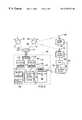
- FIG. 1shows a motion picture distribution system 20 constructed in accordance with the present invention.
- the system 20includes at least one uplink facility 22 with a dish antenna 24 which transmits encrypted video signals in digital form to a geosynchronous communications satellite 26 positioned in a relatively stationary position over a selected spot on the earth.
- the satellite 26has a plurality of transponders each of which can broadcast a separate signal to be received by ground stations.
- the system 20includes a plurality of receiving locations or theaters 28 , 30 and 32 , each having at least one dish receiving antenna 29 , 31 or 33 for receiving video signals from the satellite 26 .
- FIG. 2shows a theater 40 in which motion pictures transmitted by satellite are displayed.
- Two dish-shaped receiving antennas 42 and 44are mounted on the roof 41 of the theater. Multiple antennas are provided in order to enable the simultaneous receipt of signals from different satellites located at various positions above the earth.
- Signals received from satellitesare fed to a controller and icon decoding unit 48 and a video signal storage unit 50 , such as a magnetic disc file with relatively large storage capacity.
- the storage capacity of the unit 50may have to be in excess of one terabyte; that is, in excess of one million megabytes.
- the theater 40has rows of seats 56 secured to a sloping floor 57 , a front door 66 , and a conventional projectionist's booth 58 .
- a projection television system 52is provided.
- itis of a conventional three-tube rear-projection type which projects picture images onto the rear of a screen 54 which displays the pictures on the front surface of the screen where they can be seen by patrons of the theater sitting in the seats 56 .
- Control of the display of the motion pictureis provided from the a projectionist's booth 58 , which has a window 60 , a control panel 122 and a seat 64 for the operator.
- a front projection TV system 68can be used. Preferably, it is hung from the ceiling of the theater and projects images indicated at 70 onto the front of the projection screen 54 .
- projection TV systemscan be used to display the pictures to an audience.
- Flat panel and other equivalent display technologyalso can be used.
- FIG. 3is a top plan view of a typical multiplex theater complex 80 having a central building with seven separate theaters extending outwardly radially from the center of the complex. These theaters are labeled, respectively, # 1 , # 2 , # 3 , # 4 , # 5 , # 6 , and # 7 .
- a single antenna group and a single storage facility 86are provided for storing motion picture video images for the entire complex, and the video signals are conveyed by fiber-optic cables 84 to the individual theaters from the storage facility.
- a concession area for the complexis shown at 82 .
- the transmission of signals from a single receiving and storage facility to nearby display sites such as the theaters in the complex 80can save on equipment costs, if the distances the signals must travel to the nearby display sites is not too great.
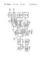
- FIG. 4illustrates the electrical equipment of the distribution system 20 shown in FIG. 1 in somewhat greater detail, and with some variations.
- Eachhas a transmitting antenna dish 24 or 100 for beaming video signals up to the satellite 26 .
- Each of the antennas 42 and 44can receive multiple signals such as those indicated at 92 and 94 simultaneously from different transponders in the satellite 26 .
- the antenna dish 44is aimed in a direction opposite to that in which the dish 42 is aimed so as to receive signals from another satellite 90 , which receives uplinked video signals from another uplink facility, as indicated at 96 .
- the signals received by the dish antennas 42 and 44are delivered to an RF switch 106 which conducts the signals to one of two receivers 108 and 110 which receives signals from one of the transponders in the satellite and sends it to a decryption unit 112 or 114 , which decrypts the encrypted signals received from the satellites.
- the decrypted signalsare sent to the controller and icon decoding unit 48 . That unit then stores the motion picture signals in the storage unit 50 .
- Additional receivers and decryption unitscan be provided to enable the receipt of additional signals.
- the operators at the receiving locationkeep track of box office and concession stand receipts during the display of each motion picture.
- This informationis input by means of an input device 122 such as a personal computer to the controller 48 . That information, together with the information regarding the identity, times of play, etc. of the motion pictures, is transmitted periodically by means of a modem 124 over telephone lines 126 to a remote business office 102 of the distributor or other entity entitled to receive the information.
- the video signalscan be transmitted by cable or other land transmission means to the local theater or other display location.
- the video signalsare encoded with code areas or icons which can take a wide variety of forms. A preferred form is shown in FIGS. 7 and 8.
- code areas or icons 160 and 161 shown in FIGS. 7 and 8are the same in principle as those disclosed in my U.S. Pat. Nos. 5,450,134 and 5,557,334, the disclosures of which hereby are incorporated herein by reference.
- the code areas or icons 160 and 161are formed in the active picture area of the video signals. That is, the icons are formed in the video picture formed by the signals.
- the iconspreferably are located in the margins of the picture so that they are hidden from the view of users of ordinary television receivers because they are outside of the “safe title border” and “safe action border” of the typical television picture. In general, such locations are preferred for use in motion picture distribution, but are less important in editing, where the general public does not see the video pictures.
- the icon indicated generally at 160is divided into three sections; the top section consisting of the contiguous horizontal line segments 162 and 164 , a middle section consisting of four horizontal line segments 166 , 168 , 170 and 172 ; and a bottom section consisting of horizontal line segments 182 and 184 .
- These sectionsare shown separated from. one another by a substantial distance for the sake of greater clarity in the drawings. Actually, they usually will be abutting one another as shown in FIG. 8 .
- the icon 160has a height of eight horizontal lines of the video picture and a width of one microsecond.
- the top and bottom sections of the iconare synchronizing signals.
- the upper line segment 162is white and the lower 164 is black.
- the upper line segment 182is white and the lower segment is 184 is black.
- the synchronizing signalsare used to indicate the icon boundaries to the system for detecting the icons.
- the particular pattern used to create synchronizationcan be varied, as desired.
- the detection of first a white line segment 162 or 182 and then a black line segment 164 or 184locates the beginning and end of the icon.
- the middle section of the iconis divided vertically into four different columns of line segments 174 , 176 , 178 and 180 . Each of the columns is 250 nano seconds wide. This creates sixteen individual code elements such as elements 186 and 188 in the resulting areas.
- Each of the separate code elementscan be given one of eight or more different predetermined luminance levels so as to provide an 8-bit code for each element.
- the area 188is white, whereas the area 186 has one of the eight different gray scale levels shown in FIG. 11 of the drawings. These gray scale levels are given the numbers 0 , 256 , 258 , 260 , 262 , 264 , 268 and 270 .
- the code element 189is all black, which corresponds to zero luminance, and white is at maximum luminance value of 100 IRE.
- the curve 254is a straight line variation with time which is used simply to exhibit the different luminance levels that each of the code elements can have.
- the code elementscan use other color variations as well to even further increase the data storage capacity of the icons.
- variations in hue or saturationcan be used as code variables.
- FIG. 8shows an icon 161 as it might appear using nothing but black and white for the code elements.
- the area 192 of the iconis entirely black, whereas the areas 194 , 196 , 198 and 200 are white.
- FIG. 6is a schematic diagram illustrating the desired locations of code areas or icons relative to the active picture areas of pictures which would be seen on video receivers by the viewer. Three different pictures 142 , 144 and 146 in a program are shown. The active picture area for each is shown at 130 .
- Icons 132 , 134 , 140 , 150 , 152 and 154are located in the left and right hand margins outside of the visible area 142 of the first picture, but within the active picture area.
- Icons 132 , 134 , 140 , 150 , 152 and 154are icons which are recorded for every video frame. These icons carry information which is useful in identifying the motion picture, and other information which applies to every frame of the video program.
- buttons 136 and 138 , and 156 and 158do not appear adjacent every frame, but are used to identify locations at which certain events should occur, or to give information which is useful for editing such as cut points, scene changes, and similar information which does not apply to every frame in the motion picture.
- the information which preferably is provided by recording icons in the video signals to be transmittedincludes the identification of the motion picture, usually by title as well as a serial number.
- the serial numberis used, preferably, because titles of motion pictures sometimes tend to be confusingly similar or identical with one another, and in order to distinguish different versions of the same film from one another. For example, serial numbers can distinguish between R rated and G rated versions of a motion picture film.
- the identification of authorized receiving locationsis also included in the icon-encoded information. This list will be used to enable the authorized receiving locations to decrypt the encrypted video signals.
- motion picturestypically contain national advertising which the theater is obliged to show along with the feature film. Also, space usually is desired by the local theater operator for local advertising.
- the iconsare used to identify the insertion locations for local advertising. This is done by marking the location of the start of the insertion, as well as the end point by means of suitably coded icons. These icons can be used by automatic icon readers in the theater to trigger a separate video source to start it in playing the local ad. The icon identifying the end of the insertion area turns off the separate video source and prevents the local ad from encroaching into program material.
- buttonsOther information encoded in the icons is that which identifies previews of coming attractions which have been selected by the local theater to be displayed. Typically, many previews will be transmitted with the program material, and each theater selects the previews it wants in advance. The icons identify which of the previews is to be displayed by the theater.
- the information stored with the help of the iconsalso can include stop and start signals for the storage device 50 . This will start the storage device 50 upon receipt of the coded signals, and stop and turn it off when storage is complete.
- Other information encoded in the iconscan include signals erasing the program from the storage device 50 when the theater has displayed the motion picture the authorized number of times, or when the time of authorization is up, thus preventing unauthorized displays of the motion picture.
- encoding schemesFor distribution purposes a number of different encoding methods can be used.
- the “IMPEG” encoding schemeis preferred.
- a high quality version of that encoding schemeis preferred so as to give the highest quality motion pictures.
- the video signals representing the motion picturesmay need enhancement to add resolution to the pictures. This increases the amount of data to be stored in the unit 50 .
- Compressionalso is preferred before encryption of the signals to be transmitted. This will reduce the time of transmission and transmission and storage costs.
- Also stored by way of iconsis a specific code number to be read from the video signals and transmitted with reports sent by modem to the distributor when reporting the displays of the motion picture. This minimizes the chances of fraud in that, if the reports which are sent do not have the special code number, it will be apparent that the information has not been obtained by detecting icons embedded in the motion picture video signals, and that the information is not necessarily valid.
- Motion picture distribution by the encryption of the video signals, and their transmission via satellite, rather than by delivering film copiesincreases security and reduces the likelihood of pirate copies being made.
- the encryption methods usedare like those used in bank transactions, and are secure against all but the most massive code-breaking attempts.
- the satelliteshould have wide-band high-powered digital transponders such as those now used by the Direct TV Company to enable home owners to use relatively small dish antennas to receive television programs from satellites.
- wide-band high-powered digital transponderssuch as those now used by the Direct TV Company to enable home owners to use relatively small dish antennas to receive television programs from satellites.
- the iconsalso can be used to automatically trigger the operation of the modem to transmit information regarding the playing of the motion picture to the distributor, once for every play of the motion picture.
- the editing system of the present inventionis illustrated schematically in FIG. 5 .
- motion picturesare filmed, usually on 35 millimeter motion picture film, at various locations.
- the film reels 222 which are exposed during each day, called “dailies,”are sent to a post-production facility 225 , as indicated at 224 .
- the dailiesare converted from film to video signals by means of a film-to-video converter such as a telecine 216 .
- the video signals producedare in digital form.
- iconsare inserted into the video signals crated in the telecine by means of an icon generator 214 .
- an icon generator 214advantageously can be of the type described in my above-identified patents.
- the icons which are appliedadd specific information to the video signals which is useful in editing the film.
- informationincludes SMPTE time code signals, scene and take numbers, and additional information which typically might be recorded by production personnel on a shoot.
- Such informationcan include his or her opinion of which of several “takes” is the best; the location at which the film is shot; the camera number from which the film is shot; and the identification of the crew members involved in the shoot. All or some of this information is useful to film editors in deciding which takes should be selected, where to make cuts and insertions, fade or dissolves and where to insert special effects etc.
- the time codescan be converted to icons by a code converter, and the other information can be input to the icon generator by means of a personal computer, for example.
- the video signals containing the iconsthen are sent to an editing system 220 , either directly or by way of video cassettes 232 .
- the editing system 220is conventional, except for its inclusion of a icon decoder 230 , which is described in the above-identified patents, and means 234 to display the information derived from the icons.
- enhancement signals from an enhancement generator 228are added, if needed to enhance the resolution of the video signals for satellite transmission in the distribution system and method described above, or for other purposes.
- the editor or editorsuse the information provided by the icons in the same way that they use similar information provided in the past.
- the resulting signalsare sent to further stations in the post production facility at which sound dubbing, special effects, sound scoring, color correction, etc. are performed.
- the digital signalscan be stored in a digital storage unit 240 .
- the digital signalscan be converted to analog form and stored on video tape by means of a VTR 242 .
- the signalscan be recorded in film form by use of conventional digital video-to-film converter 238 .
- the video signals from the digital store 240are processed in order to prepare them for transmission.
- an icon erasing circuit 244which preferably is a programmed keying amplifier programmed to replace each of the icons with video signals matching the surrounding signals so as to give the picture the same appearance as if the icons had never been inserted. Then, new icons needed to control the distribution and play of the motion pictures are added by means of another icon generator 246 .
- the signalsare compressed by means of conventional compression means 248 , and are encrypted by use of an encryption device 250 and sent to the uplink facility 252 . Then, the motion picture is distributed in the manner described above.
- edge codesit is desirable to have available to the editor of the motion picture the edge codes from the motion picture film. In prior editing systems, the edge codes often are not available.
- iconsare applied to the motion picture film 202 by means of an icon printer 226 , shown in FIG. 5 .
- the printeroperates either during the process of making the film and is used by the film maker, or the icons are applied by means of specially adapted 35 millimeter cameras which are used to film the pictures.
- the iconsare recorded as shown in FIG. 9 of the drawings.
- the icons 210are recorded in the space between the image areas 204 and 206 and the film's sprocket holes 208 .
- FIG. 10shows the additional equipment used for this purpose.
- An icon reader 212reads the icons from the motion picture film and sends corresponding signals to the telecine 216 . These signals are combined with those from the icon generator 214 . All of the icons are inserted into the video signals in the locations such as those indicated in FIG. 6 between successive frames of the video pictures. Then the video signals are sent to a cropping device 218 which eliminates all images extending along the top and bottom edges of the pictures. Editing then proceeds as described above.
- the present inventionhas significant advantages.
- the iconsbecause they appear in the active picture area of the video signals instead of the vertical interval, are not easily or frequently destroyed, altered or lost.
- the present inventionprovides more reliable information for editing purposes.
- the iconsare recorded in the active picture areas of the video signals transmitted, rather than the vertical interval as in the past, the video signals can be distributed much more reliably signals recorded in the vertical interval are subject to alteration or destruction due to compression, encryption, standards conversion, or other processing of the video signals. Such is not the case with the icons. Furthermore, because of encryption of all of the signals in the active picture area, it is extremely difficult for unauthorized persons to gain access to the icons or to the signals themselves, without authorization.
- motion picturesis intended to include not only feature films, but various commercials, previews, short features or other short subjects.
- editingis intended to include not only the cutting, positioning and arrangement of various segments of the motion picture, but also sound dubbing, “opticals”, special effects, additions, color correction and other post-production processing steps to prepare the motion picture for distribution.
Landscapes
- Engineering & Computer Science (AREA)
- Multimedia (AREA)
- Signal Processing (AREA)
- Computer Security & Cryptography (AREA)
- Databases & Information Systems (AREA)
- Computer Networks & Wireless Communication (AREA)
- Business, Economics & Management (AREA)
- Marketing (AREA)
- Television Signal Processing For Recording (AREA)
Abstract
Description
Claims (19)
Priority Applications (2)
| Application Number | Priority Date | Filing Date | Title |
|---|---|---|---|
| US09/241,945US6735776B1 (en) | 1999-02-01 | 1999-02-01 | Motion picture editing and distribution |
| US10/842,091US20040213544A1 (en) | 1999-02-01 | 2004-05-10 | Motion picture editing and distribution |
Applications Claiming Priority (1)
| Application Number | Priority Date | Filing Date | Title |
|---|---|---|---|
| US09/241,945US6735776B1 (en) | 1999-02-01 | 1999-02-01 | Motion picture editing and distribution |
Related Child Applications (1)
| Application Number | Title | Priority Date | Filing Date |
|---|---|---|---|
| US10/842,091DivisionUS20040213544A1 (en) | 1999-02-01 | 2004-05-10 | Motion picture editing and distribution |
Publications (1)
| Publication Number | Publication Date |
|---|---|
| US6735776B1true US6735776B1 (en) | 2004-05-11 |
Family
ID=32228684
Family Applications (2)
| Application Number | Title | Priority Date | Filing Date |
|---|---|---|---|
| US09/241,945Expired - LifetimeUS6735776B1 (en) | 1999-02-01 | 1999-02-01 | Motion picture editing and distribution |
| US10/842,091AbandonedUS20040213544A1 (en) | 1999-02-01 | 2004-05-10 | Motion picture editing and distribution |
Family Applications After (1)
| Application Number | Title | Priority Date | Filing Date |
|---|---|---|---|
| US10/842,091AbandonedUS20040213544A1 (en) | 1999-02-01 | 2004-05-10 | Motion picture editing and distribution |
Country Status (1)
| Country | Link |
|---|---|
| US (2) | US6735776B1 (en) |
Cited By (19)
| Publication number | Priority date | Publication date | Assignee | Title |
|---|---|---|---|---|
| US20020062481A1 (en)* | 2000-02-25 | 2002-05-23 | Malcolm Slaney | Method and system for selecting advertisements |
| US20020145678A1 (en)* | 2001-02-28 | 2002-10-10 | Nec Corporation | Video processing device, video display device and video processing method therefor and program thereof |
| US20030005449A1 (en)* | 2001-06-29 | 2003-01-02 | Mckenna Lee R. | System and method for content delivery to lodging entertainment systems |
| US20040049292A1 (en)* | 2002-09-09 | 2004-03-11 | Weigand Gilbert G. | Post-production processing |
| US20040181807A1 (en)* | 2003-03-11 | 2004-09-16 | Theiste Christopher H. | System and method for scheduling digital cinema content |
| US20040216163A1 (en)* | 2003-04-25 | 2004-10-28 | Shawn Whitcomb | System and method for digital content management and distribution of content streams within a theatre environment |
| US20060015464A1 (en)* | 2004-07-16 | 2006-01-19 | Dewolde Jeffrey H | Program encoding and counterfeit tracking system and method |
| US6993245B1 (en)* | 1999-11-18 | 2006-01-31 | Vulcan Patents Llc | Iterative, maximally probable, batch-mode commercial detection for audiovisual content |
| US7197071B1 (en) | 2002-09-09 | 2007-03-27 | Warner Bros. Entertainment Inc. | Film resource manager |
| US20070277220A1 (en)* | 2006-01-26 | 2007-11-29 | Sony Corporation | Scheme for use with client device interface in system for providing dailies and edited video to users |
| US20080028318A1 (en)* | 2006-01-26 | 2008-01-31 | Sony Corporation | Method and system for providing dailies and edited video to users |
| US20090175589A1 (en)* | 2008-01-07 | 2009-07-09 | Black Mariah, Inc. | Editing digital film |
| US20090207998A1 (en)* | 2008-01-07 | 2009-08-20 | Angus Wall | Determining unique material identifier numbers using checksum values |
| US20090210902A1 (en)* | 2000-02-25 | 2009-08-20 | Malcolm Slaney | Targeted television content display |
| US7661116B2 (en) | 2000-02-25 | 2010-02-09 | Vulcan Patents Llc | Auction for targeted content |
| US7716710B1 (en)* | 2007-05-14 | 2010-05-11 | Sprint Spectrum L.P. | Managed cooperative downloading of digital cinema content |
| USRE45406E1 (en)* | 2003-09-08 | 2015-03-03 | Deluxe Laboratories, Inc. | Program encoding and counterfeit tracking system and method |
| US8988578B2 (en) | 2012-02-03 | 2015-03-24 | Honeywell International Inc. | Mobile computing device with improved image preview functionality |
| US9195958B2 (en) | 2003-08-14 | 2015-11-24 | Regal Cinemedia Corporation | System and method for selling presentation times in a digital media stream |
Families Citing this family (2)
| Publication number | Priority date | Publication date | Assignee | Title |
|---|---|---|---|---|
| JP5877038B2 (en)* | 2010-11-19 | 2016-03-02 | 富士フイルム株式会社 | PROJECT DISPLAY METHOD AND DEVICE FOR PROJECTING IMAGE, FILM FOR PREPARATION, METHOD AND DEVICE FOR PRODUCING THE SAME, PROJECT METHOD FOR PROJECTING PROJECT IMAGE, PROGRAM, AND MOVIE SYSTEM |
| US9313242B2 (en)* | 2012-08-21 | 2016-04-12 | Skybox Imaging, Inc. | Multi-resolution pyramid for georeferenced video |
Citations (19)
| Publication number | Priority date | Publication date | Assignee | Title |
|---|---|---|---|---|
| US3848082A (en) | 1973-01-16 | 1974-11-12 | Atlantic Res Corp | System for transmitting and utilizing supplemental data via television systems |
| US3900887A (en) | 1973-01-18 | 1975-08-19 | Nippon Steel Corp | Method of simultaneous multiplex recording of picture and data and of regenerating such record and apparatus therefor |
| US4230990A (en) | 1979-03-16 | 1980-10-28 | Lert John G Jr | Broadcast program identification method and system |
| US4368486A (en) | 1980-03-04 | 1983-01-11 | Etablissement Public De Diffusion Dit "Telediffusion De France" | Television system using a marking code superimposed on the picture |
| GB2132812A (en)* | 1982-11-25 | 1984-07-11 | Sony Corp | Video theatre systems |
| US4805020A (en) | 1983-03-21 | 1989-02-14 | Greenberg Burton L | Television program transmission verification method and apparatus |
| US4807031A (en) | 1987-10-20 | 1989-02-21 | Interactive Systems, Incorporated | Interactive video method and apparatus |
| US4846693A (en) | 1987-01-08 | 1989-07-11 | Smith Engineering | Video based instructional and entertainment system using animated figure |
| US4855827A (en) | 1987-07-21 | 1989-08-08 | Worlds Of Wonder, Inc. | Method of providing identification, other digital data and multiple audio tracks in video systems |
| US4857999A (en) | 1988-12-20 | 1989-08-15 | Peac Media Research, Inc. | Video monitoring system |
| US4931871A (en) | 1988-06-14 | 1990-06-05 | Kramer Robert A | Method of and system for identification and verification of broadcasted program segments |
| US5019899A (en) | 1988-11-01 | 1991-05-28 | Control Data Corporation | Electronic data encoding and recognition system |
| US5063523A (en) | 1989-11-16 | 1991-11-05 | Racal Data Communications Inc. | Network management system with event rule handling |
| US5063493A (en) | 1989-05-22 | 1991-11-05 | Somar Corporation | Method of preparing broadcast sequence control data and apparatus for implementing said method |
| US5099319A (en) | 1989-10-23 | 1992-03-24 | Esch Arthur G | Video information delivery method and apparatus |
| US5450134A (en) | 1993-01-12 | 1995-09-12 | Visual Automation Systems, Inc. | Video facility management system for encoding and decoding video signals to facilitate identification of the video signals |
| US5557334A (en) | 1993-01-12 | 1996-09-17 | Visual Automation Systems, Inc. | Apparatus for tracking the flow of video signals by incorporating patterns of machine readable signals which will appear at predetermined locations of a television picture |
| US5960081A (en)* | 1997-06-05 | 1999-09-28 | Cray Research, Inc. | Embedding a digital signature in a video sequence |
| US6169877B1 (en)* | 1995-08-04 | 2001-01-02 | Telecom Italia S.P.A. | High density TV motion picture distribution network |
Family Cites Families (7)
| Publication number | Priority date | Publication date | Assignee | Title |
|---|---|---|---|---|
| US4783699A (en)* | 1985-07-31 | 1988-11-08 | Depaul Albert D | Apparatus and method for transmitting information by modulated video signal |
| GB8817979D0 (en)* | 1988-07-28 | 1988-09-01 | British Broadcasting Corp | Application of spectrum folding bandwidth reduction to pal ntsc & secam |
| US5091938B1 (en)* | 1990-08-06 | 1997-02-04 | Nippon Denki Home Electronics | Digital data cryptographic system |
| MY108367A (en)* | 1991-09-30 | 1996-09-30 | Thomson Consumer Electronics S A | Method and apparatus for secure transmisson of video signals. |
| US5841512A (en)* | 1996-02-27 | 1998-11-24 | Goodhill; Dean Kenneth | Methods of previewing and editing motion pictures |
| US5862299A (en)* | 1996-06-19 | 1999-01-19 | Sony Corporation | Conditional access system for local storage device |
| US6141530A (en)* | 1998-06-15 | 2000-10-31 | Digital Electronic Cinema, Inc. | System and method for digital electronic cinema delivery |
- 1999
- 1999-02-01USUS09/241,945patent/US6735776B1/ennot_activeExpired - Lifetime
- 2004
- 2004-05-10USUS10/842,091patent/US20040213544A1/ennot_activeAbandoned
Patent Citations (20)
| Publication number | Priority date | Publication date | Assignee | Title |
|---|---|---|---|---|
| US3848082A (en) | 1973-01-16 | 1974-11-12 | Atlantic Res Corp | System for transmitting and utilizing supplemental data via television systems |
| US3900887A (en) | 1973-01-18 | 1975-08-19 | Nippon Steel Corp | Method of simultaneous multiplex recording of picture and data and of regenerating such record and apparatus therefor |
| US4230990A (en) | 1979-03-16 | 1980-10-28 | Lert John G Jr | Broadcast program identification method and system |
| US4230990C1 (en) | 1979-03-16 | 2002-04-09 | John G Lert Jr | Broadcast program identification method and system |
| US4368486A (en) | 1980-03-04 | 1983-01-11 | Etablissement Public De Diffusion Dit "Telediffusion De France" | Television system using a marking code superimposed on the picture |
| GB2132812A (en)* | 1982-11-25 | 1984-07-11 | Sony Corp | Video theatre systems |
| US4805020A (en) | 1983-03-21 | 1989-02-14 | Greenberg Burton L | Television program transmission verification method and apparatus |
| US4846693A (en) | 1987-01-08 | 1989-07-11 | Smith Engineering | Video based instructional and entertainment system using animated figure |
| US4855827A (en) | 1987-07-21 | 1989-08-08 | Worlds Of Wonder, Inc. | Method of providing identification, other digital data and multiple audio tracks in video systems |
| US4807031A (en) | 1987-10-20 | 1989-02-21 | Interactive Systems, Incorporated | Interactive video method and apparatus |
| US4931871A (en) | 1988-06-14 | 1990-06-05 | Kramer Robert A | Method of and system for identification and verification of broadcasted program segments |
| US5019899A (en) | 1988-11-01 | 1991-05-28 | Control Data Corporation | Electronic data encoding and recognition system |
| US4857999A (en) | 1988-12-20 | 1989-08-15 | Peac Media Research, Inc. | Video monitoring system |
| US5063493A (en) | 1989-05-22 | 1991-11-05 | Somar Corporation | Method of preparing broadcast sequence control data and apparatus for implementing said method |
| US5099319A (en) | 1989-10-23 | 1992-03-24 | Esch Arthur G | Video information delivery method and apparatus |
| US5063523A (en) | 1989-11-16 | 1991-11-05 | Racal Data Communications Inc. | Network management system with event rule handling |
| US5450134A (en) | 1993-01-12 | 1995-09-12 | Visual Automation Systems, Inc. | Video facility management system for encoding and decoding video signals to facilitate identification of the video signals |
| US5557334A (en) | 1993-01-12 | 1996-09-17 | Visual Automation Systems, Inc. | Apparatus for tracking the flow of video signals by incorporating patterns of machine readable signals which will appear at predetermined locations of a television picture |
| US6169877B1 (en)* | 1995-08-04 | 2001-01-02 | Telecom Italia S.P.A. | High density TV motion picture distribution network |
| US5960081A (en)* | 1997-06-05 | 1999-09-28 | Cray Research, Inc. | Embedding a digital signature in a video sequence |
Cited By (42)
| Publication number | Priority date | Publication date | Assignee | Title |
|---|---|---|---|---|
| US6993245B1 (en)* | 1999-11-18 | 2006-01-31 | Vulcan Patents Llc | Iterative, maximally probable, batch-mode commercial detection for audiovisual content |
| US7778519B2 (en) | 1999-11-18 | 2010-08-17 | Interval Licensing Llc | Iterative, maximally probable, batch-mode commercial detection for audiovisual content |
| US8995820B2 (en) | 1999-11-18 | 2015-03-31 | Interval Licensing Llc | Iterative, maximally probable, batch-mode commercial detection for audiovisual content |
| US8630536B2 (en) | 1999-11-18 | 2014-01-14 | Interval Licensing Llc | Iterative, maximally probable, batch-mode commercial detection for audiovisual content |
| US20100281499A1 (en)* | 1999-11-18 | 2010-11-04 | Harville Michael L | Iterative, maximally probable, batch-mode commercial detection for audiovisual content |
| US8724967B2 (en) | 1999-11-18 | 2014-05-13 | Interval Licensing Llc | Iterative, maximally probable, batch-mode commercial detection for audiovisual content |
| US20020062481A1 (en)* | 2000-02-25 | 2002-05-23 | Malcolm Slaney | Method and system for selecting advertisements |
| US8522274B2 (en) | 2000-02-25 | 2013-08-27 | Interval Licensing Llc | System and method for selecting advertisements |
| US7661116B2 (en) | 2000-02-25 | 2010-02-09 | Vulcan Patents Llc | Auction for targeted content |
| US20100242063A1 (en)* | 2000-02-25 | 2010-09-23 | Vulcan Patents Llc | System and method for selecting advertisements |
| US8910199B2 (en) | 2000-02-25 | 2014-12-09 | Interval Licensing Llc | Targeted television content display |
| US8930990B2 (en) | 2000-02-25 | 2015-01-06 | Interval Licensing Llc | System and method for selecting advertisements |
| US8185923B2 (en) | 2000-02-25 | 2012-05-22 | Interval Licensing Llc | System and method for selecting advertisements |
| US20090210902A1 (en)* | 2000-02-25 | 2009-08-20 | Malcolm Slaney | Targeted television content display |
| US20020145678A1 (en)* | 2001-02-28 | 2002-10-10 | Nec Corporation | Video processing device, video display device and video processing method therefor and program thereof |
| US7705919B2 (en)* | 2001-02-28 | 2010-04-27 | Nec Corporation | Video processing device, video display device and video processing method therefor and program thereof |
| US7895630B2 (en)* | 2001-06-29 | 2011-02-22 | Lodgenet Interactive Corporation | System and method for content delivery to lodging entertainment systems |
| US20030005449A1 (en)* | 2001-06-29 | 2003-01-02 | Mckenna Lee R. | System and method for content delivery to lodging entertainment systems |
| US7376183B2 (en)* | 2002-09-09 | 2008-05-20 | Warner Bros. Entertainment, Inc. | Post-production processing |
| US7639740B2 (en) | 2002-09-09 | 2009-12-29 | Aol Llc | Film resource manager |
| US7379215B1 (en) | 2002-09-09 | 2008-05-27 | Warner Bros. Entertainment, Inc. | Parallel scanning and processing system |
| US7197071B1 (en) | 2002-09-09 | 2007-03-27 | Warner Bros. Entertainment Inc. | Film resource manager |
| US20040049292A1 (en)* | 2002-09-09 | 2004-03-11 | Weigand Gilbert G. | Post-production processing |
| US20040181807A1 (en)* | 2003-03-11 | 2004-09-16 | Theiste Christopher H. | System and method for scheduling digital cinema content |
| WO2004097555A3 (en)* | 2003-04-25 | 2005-06-09 | American Multi Cinema Inc | System and method for digital content management and distribution of content streams within a theatre environment |
| US20040216163A1 (en)* | 2003-04-25 | 2004-10-28 | Shawn Whitcomb | System and method for digital content management and distribution of content streams within a theatre environment |
| US9195958B2 (en) | 2003-08-14 | 2015-11-24 | Regal Cinemedia Corporation | System and method for selling presentation times in a digital media stream |
| USRE45406E1 (en)* | 2003-09-08 | 2015-03-03 | Deluxe Laboratories, Inc. | Program encoding and counterfeit tracking system and method |
| US7818257B2 (en)* | 2004-07-16 | 2010-10-19 | Deluxe Laboratories, Inc. | Program encoding and counterfeit tracking system and method |
| USRE46918E1 (en)* | 2004-07-16 | 2018-06-26 | Deluxe Laboratories Llc | Program encoding and counterfeit tracking system and method |
| US20060015464A1 (en)* | 2004-07-16 | 2006-01-19 | Dewolde Jeffrey H | Program encoding and counterfeit tracking system and method |
| US20070277220A1 (en)* | 2006-01-26 | 2007-11-29 | Sony Corporation | Scheme for use with client device interface in system for providing dailies and edited video to users |
| US8166501B2 (en) | 2006-01-26 | 2012-04-24 | Sony Corporation | Scheme for use with client device interface in system for providing dailies and edited video to users |
| US9196304B2 (en) | 2006-01-26 | 2015-11-24 | Sony Corporation | Method and system for providing dailies and edited video to users |
| US20080028318A1 (en)* | 2006-01-26 | 2008-01-31 | Sony Corporation | Method and system for providing dailies and edited video to users |
| US7996876B1 (en) | 2007-05-14 | 2011-08-09 | Sprint Spectrum L.P. | Managed cooperative downloading of digital cinema content |
| US7716710B1 (en)* | 2007-05-14 | 2010-05-11 | Sprint Spectrum L.P. | Managed cooperative downloading of digital cinema content |
| US8463109B2 (en) | 2008-01-07 | 2013-06-11 | Black Mariah, Inc. | Editing digital film |
| US20090207998A1 (en)* | 2008-01-07 | 2009-08-20 | Angus Wall | Determining unique material identifier numbers using checksum values |
| US20090175589A1 (en)* | 2008-01-07 | 2009-07-09 | Black Mariah, Inc. | Editing digital film |
| US9627002B2 (en) | 2008-01-07 | 2017-04-18 | Black Mariah, Inc. | Editing digital film |
| US8988578B2 (en) | 2012-02-03 | 2015-03-24 | Honeywell International Inc. | Mobile computing device with improved image preview functionality |
Also Published As
| Publication number | Publication date |
|---|---|
| US20040213544A1 (en) | 2004-10-28 |
Similar Documents
| Publication | Publication Date | Title |
|---|---|---|
| US6735776B1 (en) | Motion picture editing and distribution | |
| KR100354055B1 (en) | License and control system and method of electronic bulletin board system | |
| US8719878B2 (en) | Video distribution system | |
| JP5490846B2 (en) | Apparatus and method for distributing high-quality image and high-quality audio programs to remote locations | |
| RU2257015C2 (en) | Device and method for encoding and storing digital images and sound signals | |
| DE69736353T2 (en) | SYSTEM WITH CONDITIONAL ACCESS TO A LOCAL STORAGE DEVICE | |
| US20060195548A1 (en) | Video distribution system | |
| US8094876B2 (en) | Personalized marking for protecting digital audiovisual streams | |
| US20020056118A1 (en) | Video and music distribution system | |
| EP1175095A2 (en) | Video on demand pay per view services with unmodified conditional access functionality | |
| JP2004535730A (en) | Device and method for installing decryption key | |
| CN1541478A (en) | Automatic Commercial Skip Business | |
| RU2257686C2 (en) | Device and method for decoding digital signals of image and sound | |
| US4628359A (en) | Memory selecting system for scrambled television receiver | |
| AU781360B2 (en) | Video and music distribution systems | |
| Acheson et al. | Trade policy responses to new technology in the film and television industry | |
| WO2007054659A2 (en) | Layered information technology | |
| JP2002215831A (en) | Electronic cinema system and ticketing device | |
| CZ20004131A3 (en) | A method and apparatus for distributing digitized image information to presentation sites and apparatus for transmitting images representing data |
Legal Events
| Date | Code | Title | Description |
|---|---|---|---|
| STCF | Information on status: patent grant | Free format text:PATENTED CASE | |
| AS | Assignment | Owner name:LEGATE, KIM, CALIFORNIA Free format text:ASSIGNMENT OF ASSIGNORS INTEREST;ASSIGNOR:VISUAL AUTOMATION SYSTEMS, INC.;REEL/FRAME:019658/0798 Effective date:20070802 | |
| FPAY | Fee payment | Year of fee payment:4 | |
| AS | Assignment | Owner name:XL TRANSISTORS LIMITED LIABILITY COMPANY, DELAWARE Free format text:ASSIGNMENT OF ASSIGNORS INTEREST;ASSIGNOR:LEGATE, KIM;REEL/FRAME:019872/0779 Effective date:20070828 | |
| FEPP | Fee payment procedure | Free format text:PAT HOLDER NO LONGER CLAIMS SMALL ENTITY STATUS, ENTITY STATUS SET TO UNDISCOUNTED (ORIGINAL EVENT CODE: STOL); ENTITY STATUS OF PATENT OWNER: LARGE ENTITY | |
| FEPP | Fee payment procedure | Free format text:PAYER NUMBER DE-ASSIGNED (ORIGINAL EVENT CODE: RMPN); ENTITY STATUS OF PATENT OWNER: LARGE ENTITY Free format text:PAYOR NUMBER ASSIGNED (ORIGINAL EVENT CODE: ASPN); ENTITY STATUS OF PATENT OWNER: LARGE ENTITY | |
| FPAY | Fee payment | Year of fee payment:8 | |
| AS | Assignment | Owner name:MINERAL LASSEN LLC, NEVADA Free format text:MERGER;ASSIGNOR:XL TRANSISTORS LIMITED LIABILITY COMPANY;REEL/FRAME:036580/0774 Effective date:20150811 | |
| FPAY | Fee payment | Year of fee payment:12 |