US6735154B2 - Device and method for detecting cartridge readiness to load in a data storage system - Google Patents
Device and method for detecting cartridge readiness to load in a data storage systemDownload PDFInfo
- Publication number
- US6735154B2 US6735154B2US09/946,071US94607101AUS6735154B2US 6735154 B2US6735154 B2US 6735154B2US 94607101 AUS94607101 AUS 94607101AUS 6735154 B2US6735154 B2US 6735154B2
- Authority
- US
- United States
- Prior art keywords
- light
- data storage
- storage system
- data
- cartridge
- Prior art date
- Legal status (The legal status is an assumption and is not a legal conclusion. Google has not performed a legal analysis and makes no representation as to the accuracy of the status listed.)
- Expired - Fee Related, expires
Links
- 238000013500data storageMethods0.000titleclaimsabstractdescription72
- 238000000034methodMethods0.000titleclaimsdescription9
- 230000004044responseEffects0.000claimsabstractdescription18
- 230000003287optical effectEffects0.000claimsdescription4
- 230000003213activating effectEffects0.000claims2
- 230000007246mechanismEffects0.000description11
- 238000012986modificationMethods0.000description3
- 230000004048modificationEffects0.000description3
- 230000008569processEffects0.000description3
- 230000009471actionEffects0.000description2
- 239000000463materialSubstances0.000description2
- 239000002184metalSubstances0.000description2
- 241000016649Copaifera officinalisSpecies0.000description1
- 239000004859CopalSubstances0.000description1
- 239000000853adhesiveSubstances0.000description1
- 230000001070adhesive effectEffects0.000description1
- 230000000694effectsEffects0.000description1
- 230000000977initiatory effectEffects0.000description1
- 238000004519manufacturing processMethods0.000description1
- 230000000717retained effectEffects0.000description1
- 230000005236sound signalEffects0.000description1
Images


Classifications
- G—PHYSICS
- G11—INFORMATION STORAGE
- G11B—INFORMATION STORAGE BASED ON RELATIVE MOVEMENT BETWEEN RECORD CARRIER AND TRANSDUCER
- G11B17/00—Guiding record carriers not specifically of filamentary or web form, or of supports therefor
- G11B17/02—Details
- G11B17/04—Feeding or guiding single record carrier to or from transducer unit
- G11B17/041—Feeding or guiding single record carrier to or from transducer unit specially adapted for discs contained within cartridges
- G11B17/043—Direct insertion, i.e. without external loading means
- G11B17/0438—Direct insertion, i.e. without external loading means with mechanism for subsequent vertical movement of the disc and opening mechanism of the cartridge shutter
- G—PHYSICS
- G11—INFORMATION STORAGE
- G11B—INFORMATION STORAGE BASED ON RELATIVE MOVEMENT BETWEEN RECORD CARRIER AND TRANSDUCER
- G11B17/00—Guiding record carriers not specifically of filamentary or web form, or of supports therefor
- G11B17/02—Details
- G11B17/04—Feeding or guiding single record carrier to or from transducer unit
- G11B17/0401—Details
- G11B17/0405—Closing mechanism, e.g. door
- G11B17/0407—Closing mechanism, e.g. door controlling the loading of the record carrier
Definitions
- Data storage systemsi.e., disk drives
- coded video signals, audio signals, or other information signalsare typically recorded on a disk.
- a diskmay be mounted within a cartridge.
- the components of a typical data storage systeminclude a housing with an opening through which the user inserts the cartridge.
- This housingaccommodates, among other items, the mechanical and electrical subsystems for loading, reading from, writing to, and unloading the disk cartridge.
- These mechanical and electrical subsystemsare typically controlled by the data processing system (e.g., a computer) to which the data storage system is connected.
- the disk cartridgemay include a shutter that is normally closed.
- the cartridge shuttermay have one or more locking tabs associated with it.
- the corresponding data storage systemmay include a mechanism for opening the shutter on the cartridge as the cartridge is pushed into the system. As the cartridge is inserted further into the data storage system, the mechanism opens the shutter to partially expose the disk contained therein. This permits a hub of the disk to be loaded onto a spindle of a motor mounted to a base of the data storage system. The disk, when rotated by the motor, permits a read-write head to access all portions of the disk.
- a conventional disk loading and unloading system that uses disk cartridgesis typically capable of automatically transporting a disk cartridge from a receiving port onto the spindle. When the disk is no longer needed, a conventional disk loading and unloading system automatically unloads the disk from the spindle.
- a device for loading and unloading of the diskis generally constructed so that during disk loading the disk is moved horizontally, parallel to the base, towards the spindle. When the disk has been positioned above the spindle, the disk is lowered vertically onto the spindle. A spindle magnet attracts the disk hub fixed to the center of the media, thereby clamping the disk in a rotatable condition for read-write operations.
- a data storage systemhaving a base, a motor mounted to the base, and a device for detecting the presence of a data cartridge in the data storage system.
- the deviceis operatively coupled to the motor and generates a signal when the device detects the presence of the data cartridge in the data storage system.
- the motoractivates in response to generation of the signal. The motor, when activated, moves the data cartridge within the data storage system to an operational position where data may be read from or written to the data cartridge.
- the deviceincludes a light sensor and a light generator.
- the light sensoris positioned to receive light generated by the light generator.
- the light sensorgenerates the signal in response to an interruption of the light received by the sensor.
- the devicemay further include an opaque shield directly or indirectly connected to the base. This shield is movable. More particularly, the shield is movable between first and second positions. When the shield is in the first position, the sensor receives light from the light generator. In contrast, the shield blocks or interrupts the light received by the sensor when the shield is in the second position.
- the cartridgemay directly or indirectly engage and move the shield from the first position to the second position.
- FIG. 1is a perspective view of an exemplary data cartridge and an exemplary data storage system employing the present invention
- FIG. 2 ais a perspective view of the system shown in FIG. 1 with its cover removed to expose several exemplary components;
- FIG. 2 bis a top view of the system shown in FIG. 2 a;
- FIG. 3is a top view of the system shown in FIG. 2 b with a data cartridge received therein;
- FIG. 4is a perspective view of the cartridge shown in FIGS. 1 and 3;
- FIG. 5 ais a top view of the cartridge shown in FIG. 4 with the shutter open;
- FIG. 5 bis a cross-sectional view of the cartridge shown in FIG. 5 a taken along line AA thereof;
- FIG. 6 ais a perspective view of the system shown in FIG. 2 a with several components removed to illustrate several underlying exemplary components;
- FIGS. 6 b and 6 care top views of the system shown in FIG. 6 a;
- FIG. 7is an exploded, perspective view of a mechanism for loading a cartridge into an operational position
- FIG. 8is a perspective view of the mechanism shown in FIG. 7 while a cartridge is being inserted therein;
- FIG. 9is a perspective view of the mechanism shown in FIG. 7 with a cartridge fully inserted therein;
- FIG. 10is a perspective view of a load motor for loading a cartridge into the operational position, and;
- FIG. 11is a cross sectional view of the system shown in FIG. 3 taken along line BB thereof.
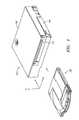
- FIG. 1is a perspective view of an exemplary data storage system 100 and an exemplary data cartridge 102 .
- Data storage systemsare often referred to as disk drives. This description will hereinafter refer to data storage system 100 as “system 100 .”
- System 100is configured to receive and to read/write data to data cartridge 102 .
- the figures of this detailed descriptionuse like reference numerals to designate like components.
- System 100includes a base 104 to which all other system 100 components are mounted, a cover 106 , and a door 110 .
- Door 110is rotatable between open and closed positions to allow manual loading or unloading of a data cartridge 102 into or out of system 100 . It is noted that two components may be directly mounted, coupled, connected or indirectly mounted, coupled, connected via one or more intermediate components.
- System 100may take form in various sizes.
- the height of system 100 measured in the z directionmay be as small as 10 mm
- the width of system 100 measured in the x directionmay be as small as 10 mm
- the length of system 100 measured in the y directionmay be as small as 45 mm. Smaller sizes of system 100 are limited only by the ability to manufacture smaller components thereof.
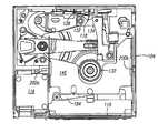
- FIGS. 2 a and 2 bare perspective and top views, respectively, of the system 100 shown in FIG. 1 with cover 106 removed to expose several exemplary components.
- exemplary internal components of system 100include a tray 112 into which data cartridge 102 (not shown in FIGS. 2 a and 2 b ) is received, a load motor 114 , and a spindle motor 116 (partially shown in FIG. 2 a , but not shown in FIG. 2 b ).
- FIG. 3shows a top view of the system 100 of FIG. 2 b with data cartridge 102 received in tray 112 .
- Load motor 114 and tray 112are two components of a mechanism for moving cartridge 102 onto spindle motor 116 after cartridge 102 is manually inserted in tray 112 .
- FIG. 4is a perspective view of data cartridge 102 shown in FIGS. 1 and 3.
- Data cartridge 102includes a cartridge shell 120 , a top sliding shutter 122 , and a bottom-sliding shutter 124 .
- the top and bottom sliding shutters 122 and 124are capable of independently sliding between open and closed states.
- shutter 122is shown closed.
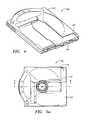
- FIG. 5 ais a top view of data cartridge 102 shown in FIG. 4 with top sliding shutter 122 in the open state to expose data storage disk 126 .
- cylinder 130 of spindle motor 116(FIG. 2) can engage and rotate data storage disk 126 while data is written thereto or read therefrom.
- FIG. 5 bis a cross-sectional view of the data cartridge 102 shown in FIG. 5 a taken along line AA thereof. As seen in FIG. 5 b , data storage disk 126 can rotate freely within cartridge shell 120 .
- Data storage disk 126 in data cartridge 102may take form in the optical data storage disk described in application Ser. No. 09/854,333 filed May 11, 2001, entitled Optical Data Storage With Enhanced Contrast.
- FIG. 6 ais a perspective view of system 100 shown in FIG. 2 a with tray 112 removed to expose several exemplary components.
- FIGS. 6 b and 6 care top views of system 100 shown in FIG. 6 a .
- FIGS. 6 a - 6 cshow a shield or flag 118 mounted to base 104 via flag spring 128 .
- the combination of flag 118 and flag spring 128need not be mounted to base 104 as shown in FIGS. 6 a - 6 c .
- the flag and flag springmay be mounted to the tray. The remaining description will presume that flag 118 and flag spring 128 are mounted to base 104 as shown in FIGS. 6 a - 6 c.
- Flag 118may be formed from an opaque material.
- flag spring 128is formed from a metal or other flexible material and includes first and second ends. The first end of flag spring 128 may be fixedly connected to base 104 using, for example, an adhesive or a weld. The second end of flag spring 128 is connected to flag 118 .
- flag 118 and flag spring 128are formed from the same piece of flat metal such that flag 118 is integrally connected to flag spring 128 .
- flag 118is movable between beam interruption and beam allowance positions.
- FIGS. 6 a and 6 bshow flag 118 in the beam interruption position
- FIG. 6 cshows flag 118 in the beam allowance position.
- Flag 118is biased to the beam allowance position by flag spring 128 .
- FIGS. 6 a - 6 balso show a light-generating device such as a light emitting diode (LED) 132 and a light sensor 134 mounted to base 104 via a printed circuit board (not shown).
- LED 132when active, generates a light beam between LED 132 and light sensor 134 .
- Light sensor 134when active, generates a signal in response to receiving the light beam generated by LED 132 or in response to an interruption of the light beam generated by LED 132 . The remaining description will presume that light sensor 134 generates a signal in response to an interruption of a light beam generated by LED 132 .
- Flag 118is movable between the beam-interruption position and the beam allowance position.
- flag 118In the beam-interruption position, as shown in FIGS. 6 a and 6 b , flag 118 is positioned between LED 132 and light sensor 134 so that flag 118 interrupts the beam of light received by sensor 134 . In other words, flag 118 shields sensor 134 from receiving light from LED 132 when flag 118 is in the beam-interruption position.
- flag 118In the beam allowance position, as shown in FIG. 6 c , flag 118 is removed from between LED 132 and light sensor 134 so that light sensor 134 may receive the light beam generated by LED 132 .
- Flag 118is normally in the beam allowance position. As will be more fully described below, flag 118 is moved from its beam allowance position to its beam-interruption position when data cartridge 102 is fully inserted into tray 112 . In one embodiment, cartridge 102 directly or indirectly engages and moves flag 118 into its beam-interruption position when cartridge 102 is inserted into tray 112 . The remaining description will presume that cartridge 102 indirectly engages and moves flag 118 into its beam-interruption position when cartridge 102 is inserted into tray 112 . When cartridge 102 is removed from tray 112 , flag spring 128 returns flag 118 to its beam allowance position shown in FIG. 6 c.
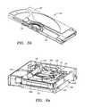
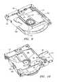
- FIG. 7is an exploded view of several components used in loading cartridge 102 into its operating position.
- FIG. 7shows tray 112 along with a picker arm 140 , a picker arm spring 142 , a picker arm pin 144 , and a cam plate 146 .
- FIG. 7shows these components isolated from base 104 .
- Tray 112is shown from below its normal position on base 104 (FIG. 2 a ).
- Tray 112includes an aperture 148 through which a portion of flag 118 (FIGS. 6 a - 6 c ) extends when flag 118 is biased to its beam allowance position.
- FIG. 8shows picker arm 140 rotatably mounted within tray 112 .
- FIG. 8also shows data cartridge 102 being inserted into tray 112 .
- Picker arm 140rotates about picker arm pin 144 between cartridge-loaded and cartridge-unloaded positions.
- Picker arm spring 142biases picker arm 140 to the cartridge-unloaded position.
- cam pins 150 a and 150 bare along the side edges of tray 112 .
- cam pins 150 a and 150 binteract with cam plate slots 196 a and 196 b of cam plate 146 (FIG. 7) and base slots 200 a and 200 b of base 104 (FIGS. 6 a - 6 c ) to move tray 112 , and data cartridge 102 loaded therein, to its operating position where data can be read from or written to data storage disk 126 of the data cartridge 102 .
- picker arm 140is in the cartridge-unloaded position and flag 118 is in the beam allowance position.
- a hook 152 at the end of picker arm 140engages bottom sliding shutter 124 of data cartridge 102 when data cartridge 102 is first inserted in tray 112 .
- picker arm 140rotates about picker arm pin 144 to slide shutter 124 to its open position thereby exposing data storage disk 126 .
- Eventually picker arm 140rotates about picker arm pin 144 and engages flag 118 (FIGS. 6 a - 6 c ) extending through aperture 148 .
- picker arm 144moves to its cartridge-loaded position, picker arm 144 pushes flag 118 to its beam-interruption position between sensor 234 and LED 132 (FIGS. 6 a and 6 b ).
- FIG. 9shows data cartridge 102 fully loaded into tray 112 .
- picker arm 140is in the cartridge-loaded position, and flag 118 has been pushed backward to its beam-interruption position (FIGS. 6 a and 6 c ).
- flag 118interrupts the beam of light between LED 132 and light sensor 134 .
- light sensor 134generates a beam interruption signal.
- the beam interruption signalis provided to drive electronics (not shown) on the printed circuit board. The beam interruption signal informs drive electronics that data cartridge 102 is fully loaded in tray 112 and ready to be moved into the operational position.
- the drive electronicsIn response to the beam interruption signal, the drive electronics generates a load-cartridge signal that activates load motor 114 shown in FIG. 10 .
- FIG. 10also shows load motor 114 coupled to cam plate 146 via lever arm 184 .
- Load motor 114can be a miniature permanent magnet DC motor manufactured by Copal of Japan (model LA8-388). The components of FIG. 10 are shown from below there normal position.
- a drive pin 162 of motor 114engages lever arm 184 by means of a cutout 186 in lever arm 184 .
- lever arm 184Welded to lever arm 184 is a pivot pin 190 that fits into a hole in base 104 (not shown in FIG. 10 ).
- load motor 114When load motor 114 is activated, load motor 114 moves drive pin 162 linearly along a lead screw 188 via a linkage more fully described in application Ser. No. 60/265,830, filed Jan. 31, 2001, and entitled Cartridge Loading Mechanism for Data Storage Disk.
- lever arm 184rotates about pivot pin 190 .
- a pin 192is connected to cam plate 146 (FIG. 7) and extends through an opening of lever arm 184 at the end opposite cutout 186 .
- Cam plate 146fits around tray 112 , with the cam pins 150 a and 150 b of tray 112 inserted into angled cam slots 190 a and 190 b , respectively, of cam plate 146 .
- pins 150 a and 150 balso fit into base slots 200 a and 200 b , respectively, of base 104 .
- cam plate slots 196 a and 196 bare angled, this has the effect of lowering tray 112 .
- tray 112is lowered, data cartridge 102 is moved into the operating position.
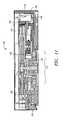
- FIG. 11is a cross-sectional view taken along line BB of FIG. 3 .
- FIG. 11shows data cartridge 102 in the operating position.
- flag 118is moved into the beam interruption position when cartridge 102 is fully inserted into tray 112 . Only after cartridge 102 is fully inserted into tray 112 will cartridge 102 be moved into the operating position.
- a timing delaymay be imposed on the initiation of the load process after flag 118 has been moved into the beam-interruption position. This delay can be used to assure that flag 118 is stationary and that the beam has been interrupted continuously for a specified amount of time. In this manner, load process reliability may be improved.
- disk 126 of cartridge 102engages cylinder 130 of spindle motor 116 .
- FIG. 11also shows flag 118 in its beam-interruption position. Flag 118 should remain in its beam-interruption position as cartridge 102 is moved into its operating position.
- load motor 114stalls and is then turned off.
- a host systeme.g., a consumer product like a digital camera, an e-book, etc.
- the system 100issues an eject command through an electronic interface to system 100
- a status checkis performed by the system 100 electronics to determine whether all write operations are complete. If a write operation is still in process, the electronics of system 100 issue a busy status indication back to the electronics of the host system through the electronic interface.
- the spindle motoris stopped and only then is the load/eject motor 114 powered in a polarity opposite from that used in the load sequence by the drive electronics (not shown).
- load motor 114is again activated to move pin 162 from the forward to the rear position.
- thiscauses cam plate 146 to move from its rear to its forward position, and by the reverse of the operation described above, tray 112 is lifted thereby removing cartridge 102 from its operating position.
- picker arm 140swings forward, partially ejecting data cartridge 102 from system 100 .
- Cartridge 102may inadvertently move from its fully loaded position in tray 112 after generation of the load cartridge signal. If data cartridge 102 is not fully loaded in tray 112 while motor 114 lowers tray 112 to its operational position, damage may result to motor 114 , tray 112 , data cartridge 102 , or other components of system 100 . To avoid this, in one embodiment load motor 114 operates to lower tray 112 only if data cartridge 102 is fully loaded in tray 112 so that flag 118 interrupts the light beam between LED 132 and light sensor 134 . If data cartridge 102 moves from its fully loaded position in tray 112 after motor 114 is activated by system electronics, flag 118 moves from its beam interruption position, thereby reestablishing the light beam between LED 132 and light sensor 134 . When the light beam is reestablished in this situation, drive electronics suspend or reverse operation of load motor 114 to avoid damaging motor 114 , tray 112 , data cartridge 102 , or other components of system 100 .
Landscapes
- Feeding And Guiding Record Carriers (AREA)
Abstract
Description
Claims (18)
Priority Applications (1)
| Application Number | Priority Date | Filing Date | Title |
|---|---|---|---|
| US09/946,071US6735154B2 (en) | 2001-01-31 | 2001-09-04 | Device and method for detecting cartridge readiness to load in a data storage system |
Applications Claiming Priority (2)
| Application Number | Priority Date | Filing Date | Title |
|---|---|---|---|
| US26583001P | 2001-01-31 | 2001-01-31 | |
| US09/946,071US6735154B2 (en) | 2001-01-31 | 2001-09-04 | Device and method for detecting cartridge readiness to load in a data storage system |
Publications (2)
| Publication Number | Publication Date |
|---|---|
| US20020101794A1 US20020101794A1 (en) | 2002-08-01 |
| US6735154B2true US6735154B2 (en) | 2004-05-11 |
Family
ID=26951444
Family Applications (1)
| Application Number | Title | Priority Date | Filing Date |
|---|---|---|---|
| US09/946,071Expired - Fee RelatedUS6735154B2 (en) | 2001-01-31 | 2001-09-04 | Device and method for detecting cartridge readiness to load in a data storage system |
Country Status (1)
| Country | Link |
|---|---|
| US (1) | US6735154B2 (en) |
Cited By (1)
| Publication number | Priority date | Publication date | Assignee | Title |
|---|---|---|---|---|
| US20020131196A1 (en)* | 2001-03-15 | 2002-09-19 | Fuji Photo Film Co., Ltd. | Disk cartridge |
Citations (26)
| Publication number | Priority date | Publication date | Assignee | Title |
|---|---|---|---|---|
| US4456935A (en) | 1980-07-29 | 1984-06-26 | Budapesti Radiotechnikai Gyar | Information recording apparatus with a disc loaded in a cassette |
| US4627039A (en) | 1983-12-23 | 1986-12-02 | Magnetic Peripherals Inc. | Head positioning servo system for optical recording with coarse and fine control |
| US4750065A (en) | 1985-10-05 | 1988-06-07 | Sony Corporation | Cartridge loading mechanism for magnetic disk drive |
| US4866693A (en) | 1986-06-13 | 1989-09-12 | Kabushiki Kaisha Toshiba | Information processing apparatus |
| US5182742A (en) | 1990-07-10 | 1993-01-26 | Sony Corporation | Recording and/or reproducing apparatus with a disc cartridge temperature sensor |
| US5202861A (en) | 1990-11-29 | 1993-04-13 | Nec Corporation | Magneto-optical disk drive having a mechanism for moving a bias magnetic field coil |
| US5485330A (en) | 1991-12-27 | 1996-01-16 | Teac Corp. | Device for loading and ejecting recording medium requiring pushing of recording medium for ejecting the medium |
| US5485329A (en) | 1993-06-01 | 1996-01-16 | Samsung Electronics Co., Ltd. | Device for inserting/extracting a disk cartridge with locking mechanism |
| US5703857A (en) | 1994-08-25 | 1997-12-30 | Discovision Associates | Cartridge-loading apparatus with improved cartridge receiver |
| US5748577A (en) | 1993-03-23 | 1998-05-05 | Nakamichi Corporation | Device for playing back disks |
| US5768241A (en)* | 1993-11-06 | 1998-06-16 | Asahi Kogaku Kogyo Kabushiki Kaisha | Shutter operating mechanism for magneto-optical disk drive |
| US5781364A (en) | 1993-02-05 | 1998-07-14 | Mitsubishi Denki Kabushiki Kaisha | Coarse and fine head positioning apparatus which uses a slipable shaft in a motor |
| US5920442A (en) | 1996-05-17 | 1999-07-06 | Sharp Kabushiki Kaisha | Cassette loading device |
| US5959956A (en) | 1995-06-15 | 1999-09-28 | Asahi Kogaku Kogyo Kabushiki Kaisha | Loading drive mechanism for disk drive |
| US6078563A (en) | 1995-09-21 | 2000-06-20 | Matsushita Electric Industrial Co., Ltd. | Disk cartridge capable of taking out a disk |
| US6118618A (en)* | 1994-11-18 | 2000-09-12 | Sony Corporation | Disk cartridge loading device for recording and/or reproducing apparatus |
| US6182899B1 (en) | 1997-09-02 | 2001-02-06 | U.S. Philips Corporation | Loading mechanism for loading and/or unloading at least one memory card into/from an electronic apparatus |
| US6262959B1 (en) | 1996-10-02 | 2001-07-17 | Sony Corporation | Disc cartridge |
| US6272093B1 (en) | 1997-05-08 | 2001-08-07 | Matsushita Electric Industrial Co., Ltd. | Disk loading device and disk adaptor |
| US6314076B1 (en)* | 1995-02-06 | 2001-11-06 | Sony Corporation | Optical pickup device in recording and/reproducing apparatus |
| US6396794B1 (en) | 1996-10-04 | 2002-05-28 | Sony Corporation | Disc recording and/or reproducing devices with disc exchanging function |
| US6404720B1 (en) | 1999-03-19 | 2002-06-11 | Sony Corporation | Disk drive |
| US6445532B1 (en) | 2000-06-07 | 2002-09-03 | Plasmon Ide, Inc. | Import/export element with lead screw and ramp for rotation |
| US6469865B1 (en) | 1999-11-16 | 2002-10-22 | Matsushita Electric Industrial Co., Ltd. | Disk apparatus |
| US6512731B1 (en)* | 1998-12-23 | 2003-01-28 | Samsung Electronics Co., Ltd. | Optical recording/reproducing apparatus and method for using various sizes, and types of recording/reproducing mediums therein |
| US6538971B2 (en)* | 1997-12-23 | 2003-03-25 | Samsung Electronics Co., Ltd. | Optical information recording/reproducing apparatus and method for using both disc cartridges holding 8cm and 12cm disc |
- 2001
- 2001-09-04USUS09/946,071patent/US6735154B2/ennot_activeExpired - Fee Related
Patent Citations (28)
| Publication number | Priority date | Publication date | Assignee | Title |
|---|---|---|---|---|
| US4456935A (en) | 1980-07-29 | 1984-06-26 | Budapesti Radiotechnikai Gyar | Information recording apparatus with a disc loaded in a cassette |
| US4627039A (en) | 1983-12-23 | 1986-12-02 | Magnetic Peripherals Inc. | Head positioning servo system for optical recording with coarse and fine control |
| US4750065A (en) | 1985-10-05 | 1988-06-07 | Sony Corporation | Cartridge loading mechanism for magnetic disk drive |
| US4866693A (en) | 1986-06-13 | 1989-09-12 | Kabushiki Kaisha Toshiba | Information processing apparatus |
| US5182742B1 (en) | 1990-07-10 | 1996-01-16 | Sony Corp | Recording and/or reproducing apparatus with a disc cartridge temperature sensor |
| US5182742A (en) | 1990-07-10 | 1993-01-26 | Sony Corporation | Recording and/or reproducing apparatus with a disc cartridge temperature sensor |
| US5202861A (en) | 1990-11-29 | 1993-04-13 | Nec Corporation | Magneto-optical disk drive having a mechanism for moving a bias magnetic field coil |
| US5485330A (en) | 1991-12-27 | 1996-01-16 | Teac Corp. | Device for loading and ejecting recording medium requiring pushing of recording medium for ejecting the medium |
| US5781364A (en) | 1993-02-05 | 1998-07-14 | Mitsubishi Denki Kabushiki Kaisha | Coarse and fine head positioning apparatus which uses a slipable shaft in a motor |
| US5748577A (en) | 1993-03-23 | 1998-05-05 | Nakamichi Corporation | Device for playing back disks |
| US5485329A (en) | 1993-06-01 | 1996-01-16 | Samsung Electronics Co., Ltd. | Device for inserting/extracting a disk cartridge with locking mechanism |
| US5768241A (en)* | 1993-11-06 | 1998-06-16 | Asahi Kogaku Kogyo Kabushiki Kaisha | Shutter operating mechanism for magneto-optical disk drive |
| US5703857A (en) | 1994-08-25 | 1997-12-30 | Discovision Associates | Cartridge-loading apparatus with improved cartridge receiver |
| US5724331A (en) | 1994-08-25 | 1998-03-03 | Discovision Associates | Disk drive system having improved cartridge-loading apparatus including direct drive gear train and methods for making and operating same |
| US6118618A (en)* | 1994-11-18 | 2000-09-12 | Sony Corporation | Disk cartridge loading device for recording and/or reproducing apparatus |
| US6314076B1 (en)* | 1995-02-06 | 2001-11-06 | Sony Corporation | Optical pickup device in recording and/reproducing apparatus |
| US5959956A (en) | 1995-06-15 | 1999-09-28 | Asahi Kogaku Kogyo Kabushiki Kaisha | Loading drive mechanism for disk drive |
| US6078563A (en) | 1995-09-21 | 2000-06-20 | Matsushita Electric Industrial Co., Ltd. | Disk cartridge capable of taking out a disk |
| US5920442A (en) | 1996-05-17 | 1999-07-06 | Sharp Kabushiki Kaisha | Cassette loading device |
| US6262959B1 (en) | 1996-10-02 | 2001-07-17 | Sony Corporation | Disc cartridge |
| US6396794B1 (en) | 1996-10-04 | 2002-05-28 | Sony Corporation | Disc recording and/or reproducing devices with disc exchanging function |
| US6272093B1 (en) | 1997-05-08 | 2001-08-07 | Matsushita Electric Industrial Co., Ltd. | Disk loading device and disk adaptor |
| US6182899B1 (en) | 1997-09-02 | 2001-02-06 | U.S. Philips Corporation | Loading mechanism for loading and/or unloading at least one memory card into/from an electronic apparatus |
| US6538971B2 (en)* | 1997-12-23 | 2003-03-25 | Samsung Electronics Co., Ltd. | Optical information recording/reproducing apparatus and method for using both disc cartridges holding 8cm and 12cm disc |
| US6512731B1 (en)* | 1998-12-23 | 2003-01-28 | Samsung Electronics Co., Ltd. | Optical recording/reproducing apparatus and method for using various sizes, and types of recording/reproducing mediums therein |
| US6404720B1 (en) | 1999-03-19 | 2002-06-11 | Sony Corporation | Disk drive |
| US6469865B1 (en) | 1999-11-16 | 2002-10-22 | Matsushita Electric Industrial Co., Ltd. | Disk apparatus |
| US6445532B1 (en) | 2000-06-07 | 2002-09-03 | Plasmon Ide, Inc. | Import/export element with lead screw and ramp for rotation |
Cited By (2)
| Publication number | Priority date | Publication date | Assignee | Title |
|---|---|---|---|---|
| US20020131196A1 (en)* | 2001-03-15 | 2002-09-19 | Fuji Photo Film Co., Ltd. | Disk cartridge |
| US6880167B2 (en)* | 2001-03-15 | 2005-04-12 | Fuji Photo Film Co., Ltd. | Disk cartridge for engaging with a sensor member of a drive device |
Also Published As
| Publication number | Publication date |
|---|---|
| US20020101794A1 (en) | 2002-08-01 |
Similar Documents
| Publication | Publication Date | Title |
|---|---|---|
| US6473261B1 (en) | Cartridge overinsertion protection for cartridge library | |
| US6945488B2 (en) | Magnetic tape drive apparatus | |
| US5612831A (en) | Removeable media drive unit with loader interlock to indicate presence of object | |
| US6735154B2 (en) | Device and method for detecting cartridge readiness to load in a data storage system | |
| US6466396B1 (en) | Cartridge library | |
| US6043954A (en) | Cartridge load and eject mechanism for a removable cartridge drive | |
| US6462900B1 (en) | Cartridge picker robot with ribbon cable for cartridge library | |
| EP0899730B1 (en) | Cartridge retention mechanism for a removable cartridge drive | |
| US6813144B2 (en) | Apparatus where media having different configurations are installed | |
| US5543993A (en) | Door opening mechanism for magnetic tape cartridge with tension control | |
| JP2003123433A (en) | Recording tape cartridge | |
| US6707638B2 (en) | Slider impedance mechanism to prevent cartridge ejection during operation | |
| US6229440B1 (en) | Cartridge drive door system | |
| JP3987542B2 (en) | Medium input device | |
| US5894377A (en) | Tray loading cartridge tape drive for different sized cartridges | |
| JP3024481B2 (en) | Disk unit | |
| WO2002061745A3 (en) | Data cartridge load/unload mechanism for disk drive | |
| JP4301109B2 (en) | Dust-proof mechanism of optical disk device | |
| US6466399B1 (en) | Cartridge latch and release system | |
| US7184243B2 (en) | Cartridge loading mechanism | |
| JPH02161664A (en) | Disk device | |
| JP2506571Y2 (en) | Cleaning Cartridge | |
| JPH02162566A (en) | Disk device | |
| JPH0633589Y2 (en) | Disk drive | |
| JPH05258431A (en) | Cartridge library device |
Legal Events
| Date | Code | Title | Description |
|---|---|---|---|
| AS | Assignment | Owner name:DATAPLAY, INC., COLORADO Free format text:ASSIGNMENT OF ASSIGNORS INTEREST;ASSIGNOR:NOWELL, SHANE G.;REEL/FRAME:012163/0856 Effective date:20010803 | |
| AS | Assignment | Owner name:DPHI ACQUISITIONS, INC., COLORADO Free format text:ASSIGNMENT OF ASSIGNORS INTEREST;ASSIGNORS:SILICON VALLEY BANK;GATX VENTURES, INC. ('GATX');SEQUEL ENTREPRENEURS' FUND II, L.P.;REEL/FRAME:014922/0216 Effective date:20030305 Owner name:SEQUEL ENTERPRENEURS' FUND II, L.P., COLORADO Free format text:ASSIGNMENT OF ASSIGNORS INTEREST;ASSIGNOR:DATAPLAY, INC.;REEL/FRAME:014922/0280 Effective date:20030304 Owner name:GATX VENTRUES, INC. ("GATX"), CALIFORNIA Free format text:ASSIGNMENT OF ASSIGNORS INTEREST;ASSIGNOR:DATAPLAY, INC.;REEL/FRAME:014922/0280 Effective date:20030304 Owner name:SILICON VALLEY BANK, CALIFORNIA Free format text:ASSIGNMENT OF ASSIGNORS INTEREST;ASSIGNOR:DATAPLAY, INC.;REEL/FRAME:014922/0280 Effective date:20030304 | |
| REMI | Maintenance fee reminder mailed | ||
| FPAY | Fee payment | Year of fee payment:4 | |
| SULP | Surcharge for late payment | ||
| REMI | Maintenance fee reminder mailed | ||
| FPAY | Fee payment | Year of fee payment:8 | |
| SULP | Surcharge for late payment | Year of fee payment:7 | |
| REMI | Maintenance fee reminder mailed | ||
| LAPS | Lapse for failure to pay maintenance fees | ||
| STCH | Information on status: patent discontinuation | Free format text:PATENT EXPIRED DUE TO NONPAYMENT OF MAINTENANCE FEES UNDER 37 CFR 1.362 | |
| FP | Lapsed due to failure to pay maintenance fee | Effective date:20160511 |