US6733523B2 - Implantable vascular graft - Google Patents
Implantable vascular graftDownload PDFInfo
- Publication number
- US6733523B2 US6733523B2US09/891,620US89162001AUS6733523B2US 6733523 B2US6733523 B2US 6733523B2US 89162001 AUS89162001 AUS 89162001AUS 6733523 B2US6733523 B2US 6733523B2
- Authority
- US
- United States
- Prior art keywords
- tubular
- proximal
- segment
- graft
- distal
- Prior art date
- Legal status (The legal status is an assumption and is not a legal conclusion. Google has not performed a legal analysis and makes no representation as to the accuracy of the status listed.)
- Expired - Lifetime
Links
- 230000002792vascularEffects0.000titleclaimsabstractdescription30
- 230000033001locomotionEffects0.000claimsabstractdescription8
- 229920001343polytetrafluoroethylenePolymers0.000claimsdescription11
- 239000004810polytetrafluoroethyleneSubstances0.000claimsdescription11
- 230000002829reductive effectEffects0.000claimsdescription8
- 238000002513implantationMethods0.000claimsdescription6
- 238000005452bendingMethods0.000claimsdescription4
- 230000000670limiting effectEffects0.000claimsdescription4
- 208000002223abdominal aortic aneurysmDiseases0.000abstractdescription13
- 208000007474aortic aneurysmDiseases0.000abstractdescription9
- 230000005012migrationEffects0.000abstractdescription9
- 238000013508migrationMethods0.000abstractdescription9
- 208000001750EndoleakDiseases0.000abstractdescription3
- 210000000709aortaAnatomy0.000description38
- 206010002329AneurysmDiseases0.000description28
- 210000002254renal arteryAnatomy0.000description21
- 230000004323axial lengthEffects0.000description16
- 239000000463materialSubstances0.000description16
- 238000013461designMethods0.000description13
- 238000000034methodMethods0.000description13
- 238000001356surgical procedureMethods0.000description13
- 238000007906compressionMethods0.000description11
- 230000006835compressionEffects0.000description11
- 230000010412perfusionEffects0.000description11
- 210000001367arteryAnatomy0.000description10
- 210000003090iliac arteryAnatomy0.000description10
- 230000003447ipsilateral effectEffects0.000description9
- 230000036961partial effectEffects0.000description9
- 230000003187abdominal effectEffects0.000description8
- 210000000702aorta abdominalAnatomy0.000description8
- 210000003484anatomyAnatomy0.000description6
- 238000004873anchoringMethods0.000description6
- 239000004744fabricSubstances0.000description6
- 238000005096rolling processMethods0.000description6
- 229920004934Dacron®Polymers0.000description4
- 208000007536ThrombosisDiseases0.000description4
- 210000001015abdomenAnatomy0.000description4
- 229910045601alloyInorganic materials0.000description4
- 239000000956alloySubstances0.000description4
- 230000000295complement effectEffects0.000description4
- 210000003414extremityAnatomy0.000description4
- 210000002216heartAnatomy0.000description4
- PXHVJJICTQNCMI-UHFFFAOYSA-NNickelChemical compound[Ni]PXHVJJICTQNCMI-UHFFFAOYSA-N0.000description3
- 239000000853adhesiveSubstances0.000description3
- 230000001070adhesive effectEffects0.000description3
- 210000000038chestAnatomy0.000description3
- 229910052751metalInorganic materials0.000description3
- 239000002184metalSubstances0.000description3
- 238000012986modificationMethods0.000description3
- 230000004048modificationEffects0.000description3
- 229920000728polyesterPolymers0.000description3
- 239000005020polyethylene terephthalateSubstances0.000description3
- 230000000452restraining effectEffects0.000description3
- 238000005476solderingMethods0.000description3
- JOYRKODLDBILNP-UHFFFAOYSA-NEthyl urethaneChemical compoundCCOC(N)=OJOYRKODLDBILNP-UHFFFAOYSA-N0.000description2
- 229920006362Teflon®Polymers0.000description2
- 238000004026adhesive bondingMethods0.000description2
- 238000013459approachMethods0.000description2
- 230000008901benefitEffects0.000description2
- 239000008280bloodSubstances0.000description2
- 210000004369bloodAnatomy0.000description2
- 230000017531blood circulationEffects0.000description2
- 238000000576coating methodMethods0.000description2
- 238000010276constructionMethods0.000description2
- 238000009826distributionMethods0.000description2
- 229940079593drugDrugs0.000description2
- 239000003814drugSubstances0.000description2
- 230000003511endothelial effectEffects0.000description2
- 238000001125extrusionMethods0.000description2
- 230000012010growthEffects0.000description2
- 238000011065in-situ storageMethods0.000description2
- 208000017169kidney diseaseDiseases0.000description2
- 210000004185liverAnatomy0.000description2
- 210000004072lungAnatomy0.000description2
- 238000004519manufacturing processMethods0.000description2
- 239000003550markerSubstances0.000description2
- 239000011159matrix materialSubstances0.000description2
- 229910052759nickelInorganic materials0.000description2
- 230000000704physical effectEffects0.000description2
- 230000008439repair processEffects0.000description2
- 238000004904shorteningMethods0.000description2
- 230000002381testicularEffects0.000description2
- 208000017667Chronic DiseaseDiseases0.000description1
- 208000034657ConvalescenceDiseases0.000description1
- 229910000599Cr alloyInorganic materials0.000description1
- 208000008952Iliac AneurysmDiseases0.000description1
- 229910001182Mo alloyInorganic materials0.000description1
- 239000004677NylonSubstances0.000description1
- 239000004698PolyethyleneSubstances0.000description1
- 239000004809TeflonSubstances0.000description1
- RTAQQCXQSZGOHL-UHFFFAOYSA-NTitaniumChemical compound[Ti]RTAQQCXQSZGOHL-UHFFFAOYSA-N0.000description1
- 210000000683abdominal cavityAnatomy0.000description1
- 210000003815abdominal wallAnatomy0.000description1
- 230000002159abnormal effectEffects0.000description1
- 230000004308accommodationEffects0.000description1
- 230000003466anti-cipated effectEffects0.000description1
- 230000005540biological transmissionEffects0.000description1
- 210000004204blood vesselAnatomy0.000description1
- 238000005219brazingMethods0.000description1
- 230000010261cell growthEffects0.000description1
- 229910052804chromiumInorganic materials0.000description1
- OGSYQYXYGXIQFH-UHFFFAOYSA-Nchromium molybdenum nickelChemical compound[Cr].[Ni].[Mo]OGSYQYXYGXIQFH-UHFFFAOYSA-N0.000description1
- 239000011248coating agentSubstances0.000description1
- 229940039231contrast mediaDrugs0.000description1
- 239000002872contrast mediaSubstances0.000description1
- 230000003247decreasing effectEffects0.000description1
- 230000010339dilationEffects0.000description1
- 238000007598dipping methodMethods0.000description1
- 229910000701elgiloys (Co-Cr-Ni Alloy)Inorganic materials0.000description1
- 210000002889endothelial cellAnatomy0.000description1
- 210000001105femoral arteryAnatomy0.000description1
- 239000000835fiberSubstances0.000description1
- 238000007667floatingMethods0.000description1
- 230000002439hemostatic effectEffects0.000description1
- 230000002706hydrostatic effectEffects0.000description1
- 238000001802infusionMethods0.000description1
- 210000000936intestineAnatomy0.000description1
- 210000003734kidneyAnatomy0.000description1
- 210000005240left ventricleAnatomy0.000description1
- 238000012423maintenanceMethods0.000description1
- 230000014759maintenance of locationEffects0.000description1
- 230000007246mechanismEffects0.000description1
- 150000002739metalsChemical class0.000description1
- 239000000203mixtureSubstances0.000description1
- 229910052750molybdenumInorganic materials0.000description1
- 238000012544monitoring processMethods0.000description1
- 229910001000nickel titaniumInorganic materials0.000description1
- HLXZNVUGXRDIFK-UHFFFAOYSA-Nnickel titaniumChemical compound[Ti].[Ti].[Ti].[Ti].[Ti].[Ti].[Ti].[Ti].[Ti].[Ti].[Ti].[Ni].[Ni].[Ni].[Ni].[Ni].[Ni].[Ni].[Ni].[Ni].[Ni].[Ni].[Ni].[Ni].[Ni]HLXZNVUGXRDIFK-UHFFFAOYSA-N0.000description1
- 229920001778nylonPolymers0.000description1
- 210000000056organAnatomy0.000description1
- 210000004197pelvisAnatomy0.000description1
- 229920009441perflouroethylene propylenePolymers0.000description1
- 210000004303peritoneumAnatomy0.000description1
- 230000035699permeabilityEffects0.000description1
- 229920000139polyethylene terephthalatePolymers0.000description1
- 239000011148porous materialSubstances0.000description1
- 230000000750progressive effectEffects0.000description1
- 210000003689pubic boneAnatomy0.000description1
- 238000011084recoveryMethods0.000description1
- 230000009467reductionEffects0.000description1
- 230000002441reversible effectEffects0.000description1
- 238000007789sealingMethods0.000description1
- 210000002151serous membraneAnatomy0.000description1
- 238000007493shaping processMethods0.000description1
- 229910000679solderInorganic materials0.000description1
- 125000006850spacer groupChemical group0.000description1
- 238000005507sprayingMethods0.000description1
- 239000010935stainless steelSubstances0.000description1
- 229910001220stainless steelInorganic materials0.000description1
- 238000006467substitution reactionMethods0.000description1
- 238000011477surgical interventionMethods0.000description1
- 230000004083survival effectEffects0.000description1
- 230000009885systemic effectEffects0.000description1
- 229910052715tantalumInorganic materials0.000description1
- GUVRBAGPIYLISA-UHFFFAOYSA-Ntantalum atomChemical compound[Ta]GUVRBAGPIYLISA-UHFFFAOYSA-N0.000description1
- 239000004753textileSubstances0.000description1
- 238000002560therapeutic procedureMethods0.000description1
- 210000001042thoracic arteryAnatomy0.000description1
- 210000000115thoracic cavityAnatomy0.000description1
- 210000001519tissueAnatomy0.000description1
- 229910052719titaniumInorganic materials0.000description1
- 239000010936titaniumSubstances0.000description1
- 229910052721tungstenInorganic materials0.000description1
- 238000011144upstream manufacturingMethods0.000description1
- 238000007631vascular surgeryMethods0.000description1
- XLYOFNOQVPJJNP-UHFFFAOYSA-NwaterSubstancesOXLYOFNOQVPJJNP-UHFFFAOYSA-N0.000description1
- 238000004804windingMethods0.000description1
Images


Classifications
- A—HUMAN NECESSITIES
- A61—MEDICAL OR VETERINARY SCIENCE; HYGIENE
- A61F—FILTERS IMPLANTABLE INTO BLOOD VESSELS; PROSTHESES; DEVICES PROVIDING PATENCY TO, OR PREVENTING COLLAPSING OF, TUBULAR STRUCTURES OF THE BODY, e.g. STENTS; ORTHOPAEDIC, NURSING OR CONTRACEPTIVE DEVICES; FOMENTATION; TREATMENT OR PROTECTION OF EYES OR EARS; BANDAGES, DRESSINGS OR ABSORBENT PADS; FIRST-AID KITS
- A61F2/00—Filters implantable into blood vessels; Prostheses, i.e. artificial substitutes or replacements for parts of the body; Appliances for connecting them with the body; Devices providing patency to, or preventing collapsing of, tubular structures of the body, e.g. stents
- A61F2/82—Devices providing patency to, or preventing collapsing of, tubular structures of the body, e.g. stents
- A61F2/86—Stents in a form characterised by the wire-like elements; Stents in the form characterised by a net-like or mesh-like structure
- A61F2/90—Stents in a form characterised by the wire-like elements; Stents in the form characterised by a net-like or mesh-like structure characterised by a net-like or mesh-like structure
- A—HUMAN NECESSITIES
- A61—MEDICAL OR VETERINARY SCIENCE; HYGIENE
- A61F—FILTERS IMPLANTABLE INTO BLOOD VESSELS; PROSTHESES; DEVICES PROVIDING PATENCY TO, OR PREVENTING COLLAPSING OF, TUBULAR STRUCTURES OF THE BODY, e.g. STENTS; ORTHOPAEDIC, NURSING OR CONTRACEPTIVE DEVICES; FOMENTATION; TREATMENT OR PROTECTION OF EYES OR EARS; BANDAGES, DRESSINGS OR ABSORBENT PADS; FIRST-AID KITS
- A61F2/00—Filters implantable into blood vessels; Prostheses, i.e. artificial substitutes or replacements for parts of the body; Appliances for connecting them with the body; Devices providing patency to, or preventing collapsing of, tubular structures of the body, e.g. stents
- A61F2/02—Prostheses implantable into the body
- A61F2/04—Hollow or tubular parts of organs, e.g. bladders, tracheae, bronchi or bile ducts
- A61F2/06—Blood vessels
- A61F2/07—Stent-grafts
- A—HUMAN NECESSITIES
- A61—MEDICAL OR VETERINARY SCIENCE; HYGIENE
- A61F—FILTERS IMPLANTABLE INTO BLOOD VESSELS; PROSTHESES; DEVICES PROVIDING PATENCY TO, OR PREVENTING COLLAPSING OF, TUBULAR STRUCTURES OF THE BODY, e.g. STENTS; ORTHOPAEDIC, NURSING OR CONTRACEPTIVE DEVICES; FOMENTATION; TREATMENT OR PROTECTION OF EYES OR EARS; BANDAGES, DRESSINGS OR ABSORBENT PADS; FIRST-AID KITS
- A61F2/00—Filters implantable into blood vessels; Prostheses, i.e. artificial substitutes or replacements for parts of the body; Appliances for connecting them with the body; Devices providing patency to, or preventing collapsing of, tubular structures of the body, e.g. stents
- A61F2/82—Devices providing patency to, or preventing collapsing of, tubular structures of the body, e.g. stents
- A61F2/856—Single tubular stent with a side portal passage
- A—HUMAN NECESSITIES
- A61—MEDICAL OR VETERINARY SCIENCE; HYGIENE
- A61F—FILTERS IMPLANTABLE INTO BLOOD VESSELS; PROSTHESES; DEVICES PROVIDING PATENCY TO, OR PREVENTING COLLAPSING OF, TUBULAR STRUCTURES OF THE BODY, e.g. STENTS; ORTHOPAEDIC, NURSING OR CONTRACEPTIVE DEVICES; FOMENTATION; TREATMENT OR PROTECTION OF EYES OR EARS; BANDAGES, DRESSINGS OR ABSORBENT PADS; FIRST-AID KITS
- A61F2/00—Filters implantable into blood vessels; Prostheses, i.e. artificial substitutes or replacements for parts of the body; Appliances for connecting them with the body; Devices providing patency to, or preventing collapsing of, tubular structures of the body, e.g. stents
- A61F2/95—Instruments specially adapted for placement or removal of stents or stent-grafts
- A61F2/954—Instruments specially adapted for placement or removal of stents or stent-grafts for placing stents or stent-grafts in a bifurcation
- A—HUMAN NECESSITIES
- A61—MEDICAL OR VETERINARY SCIENCE; HYGIENE
- A61F—FILTERS IMPLANTABLE INTO BLOOD VESSELS; PROSTHESES; DEVICES PROVIDING PATENCY TO, OR PREVENTING COLLAPSING OF, TUBULAR STRUCTURES OF THE BODY, e.g. STENTS; ORTHOPAEDIC, NURSING OR CONTRACEPTIVE DEVICES; FOMENTATION; TREATMENT OR PROTECTION OF EYES OR EARS; BANDAGES, DRESSINGS OR ABSORBENT PADS; FIRST-AID KITS
- A61F2/00—Filters implantable into blood vessels; Prostheses, i.e. artificial substitutes or replacements for parts of the body; Appliances for connecting them with the body; Devices providing patency to, or preventing collapsing of, tubular structures of the body, e.g. stents
- A61F2/82—Devices providing patency to, or preventing collapsing of, tubular structures of the body, e.g. stents
- A61F2/86—Stents in a form characterised by the wire-like elements; Stents in the form characterised by a net-like or mesh-like structure
- A61F2/89—Stents in a form characterised by the wire-like elements; Stents in the form characterised by a net-like or mesh-like structure the wire-like elements comprising two or more adjacent rings flexibly connected by separate members
- A—HUMAN NECESSITIES
- A61—MEDICAL OR VETERINARY SCIENCE; HYGIENE
- A61F—FILTERS IMPLANTABLE INTO BLOOD VESSELS; PROSTHESES; DEVICES PROVIDING PATENCY TO, OR PREVENTING COLLAPSING OF, TUBULAR STRUCTURES OF THE BODY, e.g. STENTS; ORTHOPAEDIC, NURSING OR CONTRACEPTIVE DEVICES; FOMENTATION; TREATMENT OR PROTECTION OF EYES OR EARS; BANDAGES, DRESSINGS OR ABSORBENT PADS; FIRST-AID KITS
- A61F2/00—Filters implantable into blood vessels; Prostheses, i.e. artificial substitutes or replacements for parts of the body; Appliances for connecting them with the body; Devices providing patency to, or preventing collapsing of, tubular structures of the body, e.g. stents
- A61F2/95—Instruments specially adapted for placement or removal of stents or stent-grafts
- A61F2/958—Inflatable balloons for placing stents or stent-grafts
- A—HUMAN NECESSITIES
- A61—MEDICAL OR VETERINARY SCIENCE; HYGIENE
- A61F—FILTERS IMPLANTABLE INTO BLOOD VESSELS; PROSTHESES; DEVICES PROVIDING PATENCY TO, OR PREVENTING COLLAPSING OF, TUBULAR STRUCTURES OF THE BODY, e.g. STENTS; ORTHOPAEDIC, NURSING OR CONTRACEPTIVE DEVICES; FOMENTATION; TREATMENT OR PROTECTION OF EYES OR EARS; BANDAGES, DRESSINGS OR ABSORBENT PADS; FIRST-AID KITS
- A61F2/00—Filters implantable into blood vessels; Prostheses, i.e. artificial substitutes or replacements for parts of the body; Appliances for connecting them with the body; Devices providing patency to, or preventing collapsing of, tubular structures of the body, e.g. stents
- A61F2/02—Prostheses implantable into the body
- A61F2/04—Hollow or tubular parts of organs, e.g. bladders, tracheae, bronchi or bile ducts
- A61F2/06—Blood vessels
- A61F2002/065—Y-shaped blood vessels
- A61F2002/067—Y-shaped blood vessels modular
- A—HUMAN NECESSITIES
- A61—MEDICAL OR VETERINARY SCIENCE; HYGIENE
- A61F—FILTERS IMPLANTABLE INTO BLOOD VESSELS; PROSTHESES; DEVICES PROVIDING PATENCY TO, OR PREVENTING COLLAPSING OF, TUBULAR STRUCTURES OF THE BODY, e.g. STENTS; ORTHOPAEDIC, NURSING OR CONTRACEPTIVE DEVICES; FOMENTATION; TREATMENT OR PROTECTION OF EYES OR EARS; BANDAGES, DRESSINGS OR ABSORBENT PADS; FIRST-AID KITS
- A61F2/00—Filters implantable into blood vessels; Prostheses, i.e. artificial substitutes or replacements for parts of the body; Appliances for connecting them with the body; Devices providing patency to, or preventing collapsing of, tubular structures of the body, e.g. stents
- A61F2/02—Prostheses implantable into the body
- A61F2/04—Hollow or tubular parts of organs, e.g. bladders, tracheae, bronchi or bile ducts
- A61F2/06—Blood vessels
- A61F2/07—Stent-grafts
- A61F2002/072—Encapsulated stents, e.g. wire or whole stent embedded in lining
- A—HUMAN NECESSITIES
- A61—MEDICAL OR VETERINARY SCIENCE; HYGIENE
- A61F—FILTERS IMPLANTABLE INTO BLOOD VESSELS; PROSTHESES; DEVICES PROVIDING PATENCY TO, OR PREVENTING COLLAPSING OF, TUBULAR STRUCTURES OF THE BODY, e.g. STENTS; ORTHOPAEDIC, NURSING OR CONTRACEPTIVE DEVICES; FOMENTATION; TREATMENT OR PROTECTION OF EYES OR EARS; BANDAGES, DRESSINGS OR ABSORBENT PADS; FIRST-AID KITS
- A61F2/00—Filters implantable into blood vessels; Prostheses, i.e. artificial substitutes or replacements for parts of the body; Appliances for connecting them with the body; Devices providing patency to, or preventing collapsing of, tubular structures of the body, e.g. stents
- A61F2/02—Prostheses implantable into the body
- A61F2/04—Hollow or tubular parts of organs, e.g. bladders, tracheae, bronchi or bile ducts
- A61F2/06—Blood vessels
- A61F2/07—Stent-grafts
- A61F2002/075—Stent-grafts the stent being loosely attached to the graft material, e.g. by stitching
- A—HUMAN NECESSITIES
- A61—MEDICAL OR VETERINARY SCIENCE; HYGIENE
- A61F—FILTERS IMPLANTABLE INTO BLOOD VESSELS; PROSTHESES; DEVICES PROVIDING PATENCY TO, OR PREVENTING COLLAPSING OF, TUBULAR STRUCTURES OF THE BODY, e.g. STENTS; ORTHOPAEDIC, NURSING OR CONTRACEPTIVE DEVICES; FOMENTATION; TREATMENT OR PROTECTION OF EYES OR EARS; BANDAGES, DRESSINGS OR ABSORBENT PADS; FIRST-AID KITS
- A61F2220/00—Fixations or connections for prostheses classified in groups A61F2/00 - A61F2/26 or A61F2/82 or A61F9/00 or A61F11/00 or subgroups thereof
- A61F2220/0008—Fixation appliances for connecting prostheses to the body
- A61F2220/0016—Fixation appliances for connecting prostheses to the body with sharp anchoring protrusions, e.g. barbs, pins, spikes
- A—HUMAN NECESSITIES
- A61—MEDICAL OR VETERINARY SCIENCE; HYGIENE
- A61F—FILTERS IMPLANTABLE INTO BLOOD VESSELS; PROSTHESES; DEVICES PROVIDING PATENCY TO, OR PREVENTING COLLAPSING OF, TUBULAR STRUCTURES OF THE BODY, e.g. STENTS; ORTHOPAEDIC, NURSING OR CONTRACEPTIVE DEVICES; FOMENTATION; TREATMENT OR PROTECTION OF EYES OR EARS; BANDAGES, DRESSINGS OR ABSORBENT PADS; FIRST-AID KITS
- A61F2220/00—Fixations or connections for prostheses classified in groups A61F2/00 - A61F2/26 or A61F2/82 or A61F9/00 or A61F11/00 or subgroups thereof
- A61F2220/0025—Connections or couplings between prosthetic parts, e.g. between modular parts; Connecting elements
- A61F2220/005—Connections or couplings between prosthetic parts, e.g. between modular parts; Connecting elements using adhesives
- A—HUMAN NECESSITIES
- A61—MEDICAL OR VETERINARY SCIENCE; HYGIENE
- A61F—FILTERS IMPLANTABLE INTO BLOOD VESSELS; PROSTHESES; DEVICES PROVIDING PATENCY TO, OR PREVENTING COLLAPSING OF, TUBULAR STRUCTURES OF THE BODY, e.g. STENTS; ORTHOPAEDIC, NURSING OR CONTRACEPTIVE DEVICES; FOMENTATION; TREATMENT OR PROTECTION OF EYES OR EARS; BANDAGES, DRESSINGS OR ABSORBENT PADS; FIRST-AID KITS
- A61F2220/00—Fixations or connections for prostheses classified in groups A61F2/00 - A61F2/26 or A61F2/82 or A61F9/00 or A61F11/00 or subgroups thereof
- A61F2220/0025—Connections or couplings between prosthetic parts, e.g. between modular parts; Connecting elements
- A61F2220/0058—Connections or couplings between prosthetic parts, e.g. between modular parts; Connecting elements soldered or brazed or welded
- A—HUMAN NECESSITIES
- A61—MEDICAL OR VETERINARY SCIENCE; HYGIENE
- A61F—FILTERS IMPLANTABLE INTO BLOOD VESSELS; PROSTHESES; DEVICES PROVIDING PATENCY TO, OR PREVENTING COLLAPSING OF, TUBULAR STRUCTURES OF THE BODY, e.g. STENTS; ORTHOPAEDIC, NURSING OR CONTRACEPTIVE DEVICES; FOMENTATION; TREATMENT OR PROTECTION OF EYES OR EARS; BANDAGES, DRESSINGS OR ABSORBENT PADS; FIRST-AID KITS
- A61F2220/00—Fixations or connections for prostheses classified in groups A61F2/00 - A61F2/26 or A61F2/82 or A61F9/00 or A61F11/00 or subgroups thereof
- A61F2220/0025—Connections or couplings between prosthetic parts, e.g. between modular parts; Connecting elements
- A61F2220/0075—Connections or couplings between prosthetic parts, e.g. between modular parts; Connecting elements sutured, ligatured or stitched, retained or tied with a rope, string, thread, wire or cable
- A—HUMAN NECESSITIES
- A61—MEDICAL OR VETERINARY SCIENCE; HYGIENE
- A61F—FILTERS IMPLANTABLE INTO BLOOD VESSELS; PROSTHESES; DEVICES PROVIDING PATENCY TO, OR PREVENTING COLLAPSING OF, TUBULAR STRUCTURES OF THE BODY, e.g. STENTS; ORTHOPAEDIC, NURSING OR CONTRACEPTIVE DEVICES; FOMENTATION; TREATMENT OR PROTECTION OF EYES OR EARS; BANDAGES, DRESSINGS OR ABSORBENT PADS; FIRST-AID KITS
- A61F2220/00—Fixations or connections for prostheses classified in groups A61F2/00 - A61F2/26 or A61F2/82 or A61F9/00 or A61F11/00 or subgroups thereof
- A61F2220/0025—Connections or couplings between prosthetic parts, e.g. between modular parts; Connecting elements
- A61F2220/0083—Connections or couplings between prosthetic parts, e.g. between modular parts; Connecting elements using hook and loop-type fasteners
- A—HUMAN NECESSITIES
- A61—MEDICAL OR VETERINARY SCIENCE; HYGIENE
- A61F—FILTERS IMPLANTABLE INTO BLOOD VESSELS; PROSTHESES; DEVICES PROVIDING PATENCY TO, OR PREVENTING COLLAPSING OF, TUBULAR STRUCTURES OF THE BODY, e.g. STENTS; ORTHOPAEDIC, NURSING OR CONTRACEPTIVE DEVICES; FOMENTATION; TREATMENT OR PROTECTION OF EYES OR EARS; BANDAGES, DRESSINGS OR ABSORBENT PADS; FIRST-AID KITS
- A61F2250/00—Special features of prostheses classified in groups A61F2/00 - A61F2/26 or A61F2/82 or A61F9/00 or A61F11/00 or subgroups thereof
- A61F2250/0014—Special features of prostheses classified in groups A61F2/00 - A61F2/26 or A61F2/82 or A61F9/00 or A61F11/00 or subgroups thereof having different values of a given property or geometrical feature, e.g. mechanical property or material property, at different locations within the same prosthesis
- A61F2250/0039—Special features of prostheses classified in groups A61F2/00 - A61F2/26 or A61F2/82 or A61F9/00 or A61F11/00 or subgroups thereof having different values of a given property or geometrical feature, e.g. mechanical property or material property, at different locations within the same prosthesis differing in diameter
Definitions
- the present inventionrelates to an endoluminal vascular prosthesis, and in particular, to a self-expanding bifurcated prosthesis for use in the treatment of abdominal aortic aneurysms.
- An abdominal aortic aneurysmis a sac caused by an abnormal dilation of the wall of the aorta, a major artery of the body, as it passes through the abdomen.
- the abdomenis that portion of the body which lies between the thorax and the pelvis. It contains a cavity, known as the abdominal cavity, separated by the diaphragm from the thoracic cavity and lined with a serous membrane, the peritoneum.
- the aortais the main trunk, or artery, from which the systemic arterial system proceeds. It arises from the left ventricle of the heart, passes upward, bends over and passes down through the thorax and through the abdomen to about the level of the fourth lumbar vertebra, where it divides into the two common iliac arteries.
- the aneurysmusually arises in the infrarenal portion of the diseased aorta, for example, below the kidneys. When left untreated, the aneurysm may eventually cause rupture of the sac with ensuing fatal hemorrhaging in a very short time. High mortality associated with the rupture led initially to transabdominal surgical repair of abdominal aortic aneurysms. Surgery involving the abdominal wall, however, is a major undertaking with associated high risks.
- a prosthetic devicewhich typically is a synthetic tube, or graft, usually fabricated of Polyester, Urethane, DACRON®, TEFLON®, or other suitable material.
- aortaTo perform the surgical procedure requires exposure of the aorta through an abdominal incision which can extend from the rib cage to the pubis.
- the aortamust be closed both above and below the aneurysm, so that the aneurysm can then be opened and the thrombus, or blood clot, and arteriosclerotic debris removed.
- Small arterial branches from the back wall of the aortaare tied off.
- the DACRON® tube, or graft, of approximately the same size of the normal aortais sutured in place, thereby replacing the aneurysm. Blood flow is then reestablished through the graft. It is necessary to move the intestines in order to get to the back wall of the abdomen prior to clamping off the aorta.
- the survival rate of treated patientsis markedly higher than if the surgery is performed after the aneurysm ruptures, although the mortality rate is still quite high. If the surgery is performed prior to the aneurysm rupturing, the mortality rate is typically slightly less than 10%. Conventional surgery performed after the rupture of the aneurysm is significantly higher, one study reporting a mortality rate of 66.5%. Although abdominal aortic aneurysms can be detected from routine examinations, the patient does not experience any pain from the condition. Thus, if the patient is not receiving routine examinations, it is possible that the aneurysm will progress to the rupture stage, wherein the mortality rates are significantly higher.
- Disadvantages associated with the conventional, prior art surgery, in addition to the high mortality rateinclude the extended recovery period associated with such surgery; difficulties in suturing the graft, or tube, to the aorta; the loss of the existing aorta wall and thrombosis to support and reinforce the graft; the unsuitability of the surgery for many patients having abdominal aortic aneurysms; and the problems associated with performing the surgery on an emergency basis after the aneurysm has ruptured.
- a patientcan expect to spend from one to two weeks in the hospital after the surgery, a major portion of which is spent in the intensive care unit, and a convalescence period at home from two to three months, particularly if the patient has other illnesses such as heart, lung, liver, and/or kidney disease, in which case the hospital stay is also lengthened.
- the graftmust be secured, or sutured, to the remaining portion of the aorta, which may be difficult to perform because of the thrombosis present on the remaining portion of the aorta.
- the remaining portion of the aorta wallis frequently friable, or easily crumbled.
- Parodi, et al.provide one of the first clinical descriptions of this therapy. Parodi, J. C., et al., “Transfemoral Intraluminal Graft Implantation for Abdominal Aortic Aneurysms,” 5 Annals of Vascular Surgery 491 (1991). Endovascular grafting involves the transluminal placement of a prosthetic arterial graft within the lumen of the artery.
- transluminally implantable prosthesesadapted for use in the abdominal aorta comprise a tubular wire cage surrounded by a tubular PTFE or Dacron sleeve. Both balloon expandable and self expandable support structures have been proposed. Endovascular grafts adapted to treat both straight segment and bifurcation aneurysms have also been proposed.
- the tubular prosthesiscan be self expanded at the site to treat the abdominal aortic aneurysm, and exhibits flexibility to accommodate nonlinear anatomies and normal anatomical movement.
- an endoluminal prosthesishaving an endoskeleton for supporting tubular polymeric sleeve, and a partial exoskeleton for positioning at the anatomically proximal end, to minimize migration and risks of endoleaks.
- the prosthesiscomprises at least one elongate flexible wire, formed into a plurality of axially adjacent tubular segments spaced along an axis.
- Each tubular segmentcomprises a zig-zag section of wire, having a plurality of proximal bends and distal bends. At least one of the plurality of proximal bends and plurality of distal bends have loops thereon.
- a tubular polymeric sleeveis carried by the prosthesis.
- the prosthesisis radially compressible into a first, reduced cross sectional configuration for implantation into a body lumen, and self expandable to a second, enlarged cross sectional configuration at a treatment site in a body lumen.
- At least a first portion of wire in one tubular segmentis positioned on a radially outwardly facing surface of the sleeve.
- a radially inwardly facing surface of the sleeveis in contact with a second portion of wire.
- the prosthesiscomprises at least six proximal bends on a distal segment, and at least three of the proximal bends reside on the outside of the tubular sleeve and the remainder of the proximal bends are positioned on the inside of the tubular sleeve. At least about 30%, and generally from about 40% to about 70% of the proximal bends on a distal segment reside on the outside of the tubular sleeve.
- distalrefers to catheter distal which is the same as anatomically proximal.
- the proximal bends on the inside of the tubular sleeveare connected to distal bends on a proximally adjacent segment inside of the tubular sleeve.
- a tubular wire support for a bifurcated endoluminal prosthesiscomprising a main body support structure having a proximal end, a distal end and a central lumen extending along a longitudinal axis therethrough.
- a first branch support structurehaving a proximal end, a distal end and a central lumen therethrough, is provided such that the distal end of the first branch structure is connected to the proximal end of the main body support structure.
- a second branch support structurehaving a proximal end, a distal end and a central lumen extending therethrough is provided, such that the distal end of the second branch support structure is connected to the proximal end of the main body support structure.
- a plurality of radially outwardly extending barbs or treadsare provided on the main body, integrally formed on the wire support.
- the main body support structure and first and second branch support structuresare preferably self expandable from a radially collapsed state to a radially expanded state.
- the wire in each support structureis formed into a plurality of segments, each segment comprising a series of proximal bends, a series of distal bends, and a series of struts connecting the proximal and distal bends.
- the barbsmay be formed by bending at least one of the proximal or distal bends such that it inclines radially outwardly from the longitudinal axis of the corresponding support structure.
- the anchorscomprise a plurality of distal bends on the main body support structure, to provide anchoring at the anatomically proximal end of the implanted tubular wire support.
- a tubular wire supportfor combination with a sheath to produce a flexible bifurcated endoluminal prosthesis.
- the wire supportcomprises a main body support structure having a proximal end, a distal end and a central lumen extending therethrough, the support structure comprising at least a first and second axially adjacent tubular segments. Each segment comprises a plurality of wall struts connected by proximal and distal bends.
- a first branch support structurehaving a proximal end, a distal end and a central lumen therethrough is connected to the main body support structure.
- a second branch support structurehaving a proximal end, a distal end and a central lumen extending therethrough, is connected to the main body support structure.
- At least two sliding linksare provided in between the first and second segments on the main body support structure and at least one lock is provided on a wall strut for limiting axial movement of a sliding link along that strut.
- the lockcomprises a loop formed into the strut, for limiting the effective length of travel of the sliding link along that strut. At least about 30%, and in some devices at least 50%, and in other devices 100% of the links in between the first and second segments are provided with a sliding link configuration. At least about 30%, and in some applications at least about 50% of the sliding links are provided with a lock on the corresponding strut.
- a flexible self expandable graftcomprising a tubular main body support structure, having a proximal end and a distal end.
- the tubular bodycomprises at least a first tubular segment attached to a second tubular segment.
- a tubular polymeric sleevesurrounds at least a portion of the graft.
- Each of the first and second tubular segmentscomprise a plurality of proximal bends and distal bends connected by struts, surrounding a longitudinal axis such that a first strut is on a first side of the axis and a second strut is on a second side of the axis opposing the first side.
- the first strutis shorter than the second strut.
- at least two or three or four or more adjacent segmentsare provided with a shorter strut or struts on a first side of the axis compared to the corresponding strut or struts on the second side of the axis, to facilitate curvature of the graft.
- FIG. 1is a schematic representation of a straight segment vascular prosthesis in accordance with the present invention, positioned within a symmetric abdominal aortic aneurysm.
- FIG. 2is an exploded view of an endoluminal vascular prosthesis in accordance with the present invention, showing a self expandable wire support structure separated from an outer tubular sleeve.
- FIG. 3is a plan view of a formed wire useful for rolling about an axis into a multi-segment support structure in accordance with the present invention.
- FIG. 4is an enlarged detail view of a portion of the formed wire illustrated in FIG. 3 .
- FIG. 5is a schematic view of a portion of a wire cage wall, illustrating folded link connections between adjacent apexes.
- FIG. 6is an exploded view of two opposing apexes dimensioned for one embodiment of the folded link connection of the present invention.
- FIG. 7is an enlarged view of a folded link, taken along the lines 7 — 7 in FIG. 5 .
- FIG. 8is a cross-sectional view taken along the line 8 — 8 in FIG. 7 .
- FIGS. 6A, 7 A, 8 A, 7 B, 8 B, 7 C, and 7 Dillustrate alternate embodiments of a folded link constructed from an opposing apex pair.
- FIG. 9is a partial view of a junction between two adjacent tubular segments, illustrating oppositely oriented folded links in accordance with the present invention.
- FIG. 10is a cross-section taken along the line 10 — 10 in FIG. 9 .
- FIG. 11is a schematic view of a portion of a wall of a graft, laid out flat, illustrating an alternating folded link pattern.
- FIG. 12is a wall pattern as in FIG. 11, illustrating a multi-zone folded link pattern.
- FIGS. 12A through 12Cillustrate an alternate wall pattern, which permits axially staggered links between adjacent graft segments.
- FIG. 13is a schematic illustration of a straight segment delivery catheter in accordance with the present invention, positioned within an abdominal aortic aneurysm.
- FIG. 14is an illustration as in FIG. 13, with the straight segment endoluminal prosthesis partially deployed from the delivery catheter.
- FIG. 15is a schematic representation of the abdominal aortic anatomy, with an endoluminal vascular prostheses of the present invention positioned within each of the right renal artery and the right common iliac.
- FIG. 16is a schematic representation of a straight segment graft in accordance with a further embodiment of the present invention, with side openings to permit renal perfusion.
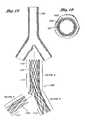
- FIG. 17is a schematic representation of a bifurcated vascular prosthesis in accordance with the present invention, positioned at the bifurcation between the abdominal aorta and the right and left common iliac arteries.
- FIG. 18is a cross-sectional view of the implanted graft taken along the lines 18 — 18 of FIG. 17 .
- FIG. 19is an exploded view of the bifurcated vascular prosthesis in accordance with the present invention, showing a two-part self expandable wire support structure separated from an outer tubular sleeve.
- FIG. 20is a plan view of formed wire useful for rolling about an axis into an aortic trunk segment and a first iliac branch segment support structure in accordance with the present invention.
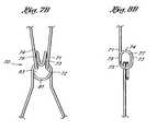
- FIG. 21is a schematic representation of another embodiment of the wire support structure for the bifurcated vascular prosthesis of the present invention, showing a main body support structure and separate branch support structures.
- FIG. 22is a schematic representation of the three-part wire support structure as in FIG. 21, illustrating the sliding articulation between the branch supports and the main body support.
- FIG. 23is a plan view of formed wire useful for rolling about an axis to form a branch support structure in accordance with the three-part support embodiment of the present invention shown in FIG. 21 .
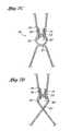
- FIGS. 24A, 24 B and 24 Care enlargements of the apexes delineated by lines A, B and C, respectively, in FIG. 23 .
- FIG. 25is side elevational cross-section of a bifurcation graft delivery catheter in accordance with the present invention.
- FIG. 26is an enlargement of the portion delineated by the line 26 — 26 in FIG. 25 .
- FIG. 27is a cross-section taken along the line 27 — 27 in FIG. 26 .
- FIG. 28is a cross-section taken along the line 28 — 28 in FIG. 26 .
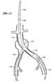
- FIG. 29is a schematic representation of a bifurcated graft deployment catheter of the present invention, positioned within the ipsilateral iliac and the aorta, with the contralateral guidewire positioned within the contralateral iliac.
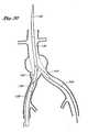
- FIG. 30is a schematic representation as in FIG. 29, with the outer sheath proximally retracted and the compressed iliac branches of the graft moving into position within the iliac arteries.
- FIG. 31is a schematic representation as in FIG. 30, with the compressed iliac branches of the graft within the iliac arteries, and the main aortic trunk of the graft deployed within the aorta.
- FIG. 32is a schematic representation as in FIG. 31, with the contralateral iliac branch of the graft deployed.
- FIG. 33is a schematic representation as in FIG. 32, following deployment of the ipsilateral branch of the graft.
- FIG. 34 ais a side elevational view of a flexible straight graft in accordance with the present invention.
- FIG. 34 bis a detail view of a sliding link in the embodiment of FIG. 34 a.
- FIG. 34 cis a side elevational view of the graft of FIG. 34 a, having a radius of curvature.
- FIG. 34 dis a detail view as in FIG. 34 b, illustrating a lock for limiting axial compression of the sliding link.
- FIG. 35 ais a side elevational view of a bifurcated graft which includes sliding links in accordance with the present invention.
- FIG. 35 bis a detail view of a sliding link in a proximal portion of the graft of FIG. 35 a.
- FIG. 35 cis a detail view of a folded link utilized in an intermediate zone of the graft of FIG. 35 a.
- FIG. 35 dis a detail view of a sliding link utilized in the iliac branches of the graft of FIG. 35 a.
- FIG. 36is a side elevational view of a tapered bifurcated graft in accordance with the present invention.
- FIG. 37is a schematic side elevational view of a graft having short graft sections on one side to facilitate a curve.
- FIG. 38 aillustrates a bifurcation or straight segment graft having a plurality of proximal barbs.
- FIG. 38 bis a detailed view of a barb of the type illustrated in FIG. 38 a.
- FIG. 38 cis an alternate barb configuration.
- FIG. 39 ais a fractional side elevational view of a graft assembly having a partial exoskeleton.
- FIG. 39 bis a partial side elevational view of an alternate exoskeleton configuration.
- FIG. 39 cis a partial side elevational view of a second alternate partial exoskeleton configuration.
- FIG. 1there is disclosed a schematic representation of the abdominal part of the aorta and its principal branches.
- the abdominal aorta 30is characterized by a right renal artery 32 and left renal artery 34 .
- the large terminal branches of the aortaare the right and left common iliac arteries 36 and 38 .
- Additional vesselse.g., second lumbar, testicular, inferior mesenteric, middle sacral
- a generally symmetrical aneurysm 40is illustrated in the infrarenal portion of the diseased aorta.
- An expanded straight segment endoluminal vascular prosthesis 42in accordance with the present invention, is illustrated spanning the aneurysm 40 .
- the endoluminal vascular prosthesis 42includes a polymeric sleeve 44 and a tubular wire support 46 , which are illustrated in situ in FIG. 1 .
- the sleeve 44 and wire support 46are more readily visualized in the exploded view shown in FIG. 2 .
- the endoluminal prosthesis 42 illustrated and described hereindepicts an embodiment in which the polymeric sleeve 44 is situated concentrically outside of the tubular wire support 46 .
- other embodimentsmay include a sleeve situated instead concentrically inside the wire support or on both of the inside and the outside of the wire support.
- the wire supportmay be embedded within a polymeric matrix which makes up the sleeve.
- the sleeve 44may be attached to the wire support by any of a variety of means, including laser bonding, adhesives, clips, sutures, dipping or spraying or others, depending upon the composition of the sleeve 44 and overall graft design.
- the polymeric sleeve 44may be formed from any of a variety of synthetic polymeric materials, or combinations thereof, including PTFE, PE, PET, Urethane, Dacron, nylon, polyester or woven textiles.
- the sleeve materialexhibits relatively low inherent elasticity, or low elasticity out to the intended enlarged diameter of the wire cage 46 .
- the sleeve materialpreferably has a thin profile, such as no larger than about 0.002 inches to about 0.005 inches.
- the material of sleeve 44is sufficiently porous to permit ingrowth of endothelial cells, thereby providing more secure anchorage of the prosthesis and potentially reducing flow resistance, sheer forces, and leakage of blood around the prosthesis.
- Porosity in polymeric sleeve materialsmay be estimated by measuring water permeability as a function of hydrostatic pressure, which will preferably range from about 3 to 6 psi.
- the porosity characteristics of the polymeric sleeve 44may be either homogeneous throughout the axial length of the prosthesis 42 , or may vary according to the axial position along the prosthesis 42 . For example, referring to FIGS. 1 and 2, different physical properties will be called upon at different axial positions along the prosthesis 42 in use. At least a proximal portion 55 and a distal portion 59 of the prosthesis 42 will seat against the native vessel wall, proximally and distally of the aneurysm. In these proximal and distal portions, the prosthesis preferably encourages endothelial growth, or, at least, permits endothelial growth to infiltrate portions of the prosthesis in order to enhance anchoring and minimize leakage.
- a central portion 57 of the prosthesisspans the aneurysm, and anchoring is less of an issue. Instead, maximizing lumen diameter and minimizing blood flow through the prosthesis wall become primary objectives.
- the polymeric sleeve 44may either be nonporous, or provided with pores of relatively lower porosity
- a multi-zoned prosthesis 42may also be provided in accordance with the present invention by positioning a tubular sleeve 44 on a central portion 57 of the prosthesis, such that it spans the aneurysm to be treated, but leaving a proximal attachment zone 55 and a distal attachment zone 59 of the prosthesis 42 having exposed wires from the wire support 46 .
- the exposed wires 46are positioned in contact with the vessel wall both proximally and distally of the aneurysm, such that the wire, over time, may become embedded in cell growth on the interior surface of the vessel wall.
- the sleeve 44 and/or the wire support 46is tapered, having a relatively larger expanded diameter at the proximal end 50 compared to the distal end 52 . See, e.g., FIG. 36, discussed below.
- the tapered designmay allow the prosthesis to conform better to the natural decreasing distal cross-section of the vessel, to reduce the risk of graft migration and potentially create better flow dynamics.
- the cage 46can be provided with a proximal zone 55 and distal zone 59 that have a larger average expanded diameter than the central zone 57 , as illustrated in FIG. 2 . This configuration may desirably resist migration of the prosthesis within the vessel and reduce leakage around the ends of the prosthesis.
- the tubular wire support 46may be formed from a continuous single length of round or flattened wire. Alternatively, two or more wire lengths can be secured together to produce the wire support 46 .
- the wire support 46is preferably formed in a plurality of discrete tubular segments 54 , connected together and oriented about a common axis. Each pair of adjacent segments 54 is connected by a connector 66 as illustrated in FIG. 3 .
- the connectors 66collectively produce a generally axially extending backbone which adds axial strength to the prosthesis 42 . Adjacent segments can be connected both by the backbone, as well as the interlocking junction disclosed below. Additional structures, including circumferentially extending sutures, solder joints, and wire loops may also be used.
- Each segment 54though joined to adjacent segments, may be independently engineered to yield desired parameters.
- Each segmentmay range in axial length from about 0.3 to about 5 cm, and may be a uniform or non-uniform length around its circumference, such as to facilitate curvature as is discussed below. Generally, the shorter their length the greater the radial strength.
- An endoluminal prosthesismay include from about 1 to about 50 segments, preferably from about 3 to about 10 segments.
- a short graft patchin accordance with the invention, may comprise only 2 segments and span a total of 2 to 3 cm, a complete graft may comprise 4 or more segments and span the entire aortic aneurysm.
- further flexibilitycan be achieved through adjustments in the number, angle, or configuration of the wire bends associated with the tubular support. See, eg., FIGS. 34 and 35, discussed below.
- different zonescan be provided with a different radial expansion force, such as ranging from about 0.2 lbs. to about 0.8 lbs.
- the proximal zone 55is provided with a greater radial force than the central zone 57 and/or distal zone 59 .
- the greater radial forcecan be provided in any of a variety of manners discussed elsewhere herein, such as through the use of an additional one or two or three or more proximal bends 60 , distal bends 62 and wall sections 64 compared to a reference segment 54 in the central zone 57 or distal zone 59 .
- additional spring forcecan be achieved in the proximal zone 55 through the use of the same number of proximal bends 60 as in the rest of the prosthesis, but with a heavier gauge wire.
- the wiremay be made from any of a variety of different alloys, such as elgiloy, nitinol or MP35N, or other alloys which include nickel, titanium, tantalum, or stainless steel, high Co-Cr alloys or other temperature sensitive materials.
- elgiloy, nitinol or MP35Nor other alloys which include nickel, titanium, tantalum, or stainless steel, high Co-Cr alloys or other temperature sensitive materials.
- an alloycomprising Ni 15%, Co 40%, Cr 20%, Mo 7% and balance Fe may be used.
- the tensile strength of suitable wireis generally above about 300 Ksi and often between about 300 and about 340 Ksi for many embodiments.
- a Chromium-Nickel-Molybdenum alloysuch as that marketed under the name Conichrom (Fort Wayne Metals, Ind.) has a tensile strength ranging from 300 to 320 K psi, elongation of 3.5-4.0%.
- the wiremay be treated with a plasma coating and be provided with or without additional coatings such as PTFE, Teflon, Perlyne and drugs.
- radial strengthmeasured at 50% of the collapsed profile, preferably ranges from about 0.2 lb. to 0.8 lb., and generally from about 0.4 lb. to about 0.5 lb. or more.
- Preferred wire diameters in accordance with the present inventionrange from about 0.004 inches to about 0.020 inches. More preferably, the wire diameters range from about 0.006 inches to about 0.018 inches. In general, the greater the wire diameter, the greater the radial strength for a given wire layout.
- the wire gaugecan be varied depending upon the application of the finished graft, in combination with/or separate from variation in other design parameters (such as the number of struts, or proximal bends 60 and distal bends 62 per segment), as will be discussed.
- a wire diameter of approximately 0.018 inchesmay be useful in a graft having four segments each having 2.5 cm length per segment, each segment having six struts intended for use in the aorta, while a smaller diameter such as 0.006 inches might be useful for a 0.5 cm segment graft having 5 struts per segment intended for the iliac artery.
- the length of cage 42could be as long as about 28 cm.
- the wire diameteris tapered from the proximal to distal ends.
- the wire diametermay be tapered incrementally or stepped down, or stepped up, depending on differing radial strength requirements along the length of the graft for each particular clinical application.
- the wirehas a cross-section of about 0.018 inches in the proximal zone 55 and the wire tapers down to a diameter of about 0.006 inches in the distal zone 59 of the graft 42 . End point dimensions and rates of taper can be varied widely, within the spirit of the present invention, depending upon the desired clinical performance.
- FIG. 3there is illustrated a plan view of a single formed wire used for rolling about a longitudinal axis to produce a four segment straight tubular wire support.
- the formed wireexhibits distinct segments, each corresponding to an individual tubular segment 54 in the tubular support (see FIGS. 1 and 2 ).
- Each segmenthas a repeating pattern of proximal bends 60 connected to corresponding distal bends 62 by wall sections 64 which extend in a generally zig-zag configuration when the segment 54 is radially expanded.
- Each segment 54is connected to the adjacent segment 54 through a connector 66 , except at the terminal ends of the graft.
- the connector 66 in the illustrated embodimentcomprises two wall or strut sections 64 which connect a proximal bend 60 on a first segment 54 with a distal bend 62 on a second, adjacent segment 54 .
- the connector 66may additionally be provided with a connector bend 68 , which may be used to impart increased radial strength to the graft and/or provide a tie site for a circumferentially extending suture.
- a proximal bend 60comprises about a 180 degree arc, having a radial diameter of (w) (Ranging from 0.070 to 0.009 inches), depending on wire diameter followed by a relatively short length of parallel wire spanning an axial distance of d 1 .
- the parallel wiresthereafter diverge outwardly from one another and form the strut sections 64 , or the proximal half of a connector 66 .
- the wireforms a distal bend 62 , preferably having identical characteristics as the proximal bend 60 , except being concave in the opposite direction.
- the axial direction component of the distance between the apices of the corresponding proximal and distal bends 60 , 62 on a given strut section 64is referred to as (d) and represents the axial length of that segment.
- the total expanded angle defined by the bend 60 and the divergent strut sections 64is represented by ⁇ . Upon compression to a collapsed state, such as when the graft is within the deployment catheter, the angle ⁇ is reduced to ⁇ ′.
- ⁇is generally within the range of from about 35° to about 45° for a six apex section having an axial length of about 1.5 cm or 2 cm and a diameter of about 25 mm or 28 mm .
- the expanded circumferential distance between any two adjacent distal bends 62 (or proximal bends 60 )is defined as (s).
- the diameter W of each proximal bend 60 or distal bend 62is within the range of from about 0.009 inches to about 0.070 inches depending upon the wire diameter.
- Diameter Wis preferably as small as possible for a given wire diameter and wire characteristics. As will be appreciated by those of skill in the art, as the distance W is reduced to approach two times the cross-section of the wire, the bend 60 or 62 will exceed the elastic limit of the wire, and radial strength of the finished segment will be lost. Determination of a minimum value for W, in the context of a particular wire diameter and wire material, can be readily determined through routine experimentation by those of skill in the art.
- the sum of the distances (s) in a plane transverse to the longitudinal axis of the finished graftwill correspond to the circumference of the finished graft cage in that plane.
- the number of proximal bends 60 or distal bends 62is directly related to the distance (s) in the corresponding plane.
- the finished graft in any single transverse planewill have from about 3 to about 10 (s) dimensions, preferably from about 4 to about 8 (s) dimensions and, more preferably, about 5 or 6 (s) dimensions for an aortic application.
- Each (s) dimensioncorresponds to the distance between any two adjacent bends 60 — 60 or 62 — 62 as will be apparent from the discussion herein.
- Each segment 54can thus be visualized as a series of triangles extending circumferentially around the axis of the graft, defined by a proximal bend 60 and two distal bends 62 or the reverse.
- wis about 2.0 mm ⁇ 1 mm for a 0.018 inch wire diameter.
- D 1is about 3 mm ⁇ 1 mm, and d is about 20 mm ⁇ 1 mm.
- Specific dimensions for all of the foregoing variablescan be varied considerably, depending upon the desired wire configuration, in view of the disclosure herein.
- one or more apexes 76is provided with an elongated axial length d 2 , which permits the apex 76 to be wrapped around a corresponding portion 78 such as an apex of the adjacent segment to provide an interlocking link 70 between two axially adjacent cage segments.
- d 1is generally within the range of from about 1 mm to about 4 mm and d 2 is within the range of from about 5 mm to about 9 mm.
- a longer d 2 dimensionpermits accommodation for greater axial travel of apex 78 with respect to 76 , as will be discussed, thereby permitting greater lateral flexibility of the graft.
- W 1is within the range of from about 3 mm to about 5 mm, and W 2 is sufficiently less than W 1 that the apex 76 can fit within the apex 78 .
- Any of a wide variety of specific apex configurations and dimensionscan be utilized, as will be apparent to those of skill in the art in view of the disclosure herein. Regardless of the specific dimensions, the end of the apex 76 is advanced through the apex 78 , and folded back upon its self to hook the apex 78 therein to provide a link 70 in accordance with the present invention.
- the resulting link 70(see FIGS. 7 and 8) comprises a wall portion 71 extending in a first direction, substantially parallel to the axis of the graft, and a transverse portion 72 extending transverse to the axis of the graft.
- a return portion 73extends generally in the opposite direction from the wall portion 71 to create a generally “U” shaped hook.
- a closing portion 74is also provided, to minimize the risk of excessive axial compression of the wire cage.
- the forgoing structureproduces a functionally closed aperture 77 , which receives the interlocking section 75 of the adjacent graft segment. Alternatively, see FIG. 10 .
- the aperture 77preferably has a width (as viewed in FIG. 8) in the radial graft direction of substantially equal to the radial direction dimension of the interlocking section 75 .
- the interlocking section 75as well as the locking portion 71 and return portion 73 can be flattened in the radial direction, to minimize the transverse cross-section of the link 70 .
- the aperture 77is preferably greater than the axial direction dimension of the interlocking section 75 , to accommodate some axial movement of each adjoining tubular segment of the graft.
- the axial length of the aperture 77is at least about 2 times, and preferably at least about 3 or 4 times the cross-section of the interlocking section 75 .
- the optimum axial length of the aperture 77can be determined through routine experimentation by one of skill in the art in view of the intended clinical performance, taking into account the number of links 70 per transverse plane as well as the desired curvature of the finished graft.
- FIGS. 6A, 7 A and 8 Aillustrate an alternate configuration for the moveable link 70 . With this configuration, the radial expansion force will be higher.
- FIGS. 7B and 8Billustrate another alternate configuration. This linkage has a better resistance to axial compression and disengagement.
- the apexextends beyond closing portion 74 and into an axial portion 79 which extends generally parallel to the longitudinal axis of the graft. Provision of an axial extension 79 provides a more secure enclosure for the aperture 77 as will be apparent to those of skill in the art.
- the embodiments of FIG. 7B and 8Balso illustrate an enclosed aperture 83 on the opposing apex. The aperture 83 is formed by wrapping the apex in at least one complete revolution so that a generally circumferentially extending portion 81 is provided.
- Circumferential portion 81provides a stop, to limit axial compressibility of the graft.
- the closed aperture 83can be formed by winding the wire of the apex about a mandrel either in the direction illustrated in FIG. 7B, or the direction illustrated in FIG. 7 C.
- the embodiment of FIG. 7Cadvantageously provided only a single wire thickness through the aperture 77 , thereby minimizing the wall thickness of the graft. This is accomplished by moving the crossover point outside of the aperture 77 , as will be apparent from FIG. 7 C.
- link 70 in accordance with the present inventionis preferably formed integrally with the wire which forms the cage of the endovascular prosthesis.
- link 70may be constructed from a separate material which is secured to the wire cage such as by soldering, suture, wrapping or the like.
- the axial direction of the link 70may also be varied, depending upon the desired performance characteristics of the graft.
- the distal tips 76 of each link 70may all face the same direction, such as proximal or distal with respect to the graft. See, for example, FIG. 5 .
- one or more links in a given transverse plane of apexesmay face in a proximal direction, and one or more links in the same transverse plane may face in the opposite direction. See, for example, FIG. 9 .
- At least one and preferably at least two links 70are provided per transverse plane separating adjacent graft segments.
- preferably at least two or three and in one embodiment all six opposing apex pairsare provided with a link 70 . See FIG. 5 .
- each opposing apex pair between adjacent tubular segmentscan be provided with a link 70 . See FIG. 5 .
- interlocking links 70may be spaced circumferentially apart around the graft wall such as by positioning them at every second or third opposing apex pair.
- the distribution of the links 70may also be varied along the axial length of the graft.
- a first zone at a proximal end of the graft and a second zone at a distal end of the graftmay be provided with a relatively larger number of links 70 than a third zone in the central portion of the graft.
- the transverse apex plane between the first and second tubular segments at the proximal end of the graftmay be provided with a link 70 at each opposing apex pair.
- each opposing pair of apexesis provided with a link 70 .
- the central transverse apex planethree of the six apex pairs are provided with a links 70 , spaced apart at approximately 120°. Substantially equal circumferential spacing of the link 70 is preferred, to provide relatively uniform resistance to bending regardless of graft position.
- the distal transverse apex planemay also be provided with a link 70 at each opposing apex pair.
- interlocking link 70 in accordance with the present inventioncan be readily adapted to both the straight segment grafts as discussed above, as well as to the bifurcated grafts discussed below.
- the interlocking link 70can be utilized to connect any of a number of independent graft segments in axial alignment to produce either a straight segment or a bifurcation graft.
- the interlocking link 70may be utilized as the sole means of securing adjacent segments to each other, or may be supplemented by additional attachment structures such as metal loops, sutures, welds and others which are well understood in the art.
- FIGS. 12A through 12Cthere is illustrated a further wire layout which allows a smaller collapsed profile for the vascular graft.
- the embodiment of FIGS. 12A through 12Cpermits a series of links 70 A and 70 B to be staggered axially from one another as seen in FIG. 12A and 12B. In this manner, adjacent links 70 do not lie in the same transverse plane, and permit a tighter nesting of the collapsed wire cage.
- at least a first group of links 70 Ais offset axially from a second group of links 70 B.
- a first group of every other apex 70 Amay be positioned slightly proximally of a second group of every other apex 70 B. Referring to FIG. 12C, this may be accomplished by extending an apex 76 A by a d 3 distance which is at least about 1.2 times and as large as 1.5 times or 2 times or more the distance d 2 .
- the corresponding apexes 78 and 78 Aare similarly staggered axially, to produce the staggered interface between adjacent graft segments illustrated in FIG. 12 A.
- a loop apexis illustrated in FIG.
- any of the alternate apexes illustrated hereincan be utilized in the staggered apex embodiment of the invention.
- the zig-zag pattern produced by axially offset links 70 A and 70 Bcan reside in a pair of parallel transverse planes extending generally between adjacent segments of the graft.
- the zig-zag relationship between adjacent links 70 A and 70 Bcan spiral around the circumference of a graft in a helical pattern, as will be understood by those of skill in the art in view of the disclosure herein.
- the precise axial offset between adjacent staggered links 70 A and 70 Bcan be optimized by one of ordinary skill in the art through routine experimentation, taking into account the desired physical properties and collapsed profile of the graft.
- a delivery catheter 80having a dilator tip 82 , is advanced along guidewire 84 until the (anatomically) proximal end 50 of the collapsed endoluminal vascular prosthesis 88 is positioned between the renal arteries 32 and 34 and the aneurysm 40 .
- the collapsed prosthesis in accordance with the present inventionhas a diameter in the range of about 2 to about 10 mm. Generally, the diameter of the collapsed prosthesis is in the range of about 3 to 6 mm (12 to 18 French).
- the delivery catheter including the prosthesiswill be 16 F, or 15 F or 14 F or smaller.
- the prosthesis 88is maintained in its collapsed configuration by the restraining walls of the tubular delivery catheter 80 , such that removal of this restraint would allow the prosthesis to self expand.
- Radiopaque marker materialmay be incorporated into the delivery catheter 80 , and/or the prosthesis 88 , at least at both the proximal and distal ends, to facilitate monitoring of prosthesis position.
- the dilator tip 82is bonded to an internal catheter core 92 , as illustrated in FIG. 14, so that the internal catheter core 92 and the partially expanded prosthesis 88 are revealed as the outer sheath of the delivery catheter 80 is retracted.
- the collapsed prosthesis 88remains substantially fixed axially relative to the internal catheter core 92 and consequently, self-expands at a predetermined vascular site as illustrated in FIG. 14 .
- the expanded endoluminal vascular prosthesis 88has radially self-expanded to a diameter anywhere in the range of about 20 to 40 mm, corresponding to expansion ratios of about 1:2 to 1:20.
- the expansion ratiosrange from about 1:4 to 1:8, more preferably from about 1:4 to 1:6.
- the prosthesis 88may be maintained in its collapsed configuration by a restraining lace, which may be woven through the prosthesis or wrapped around the outside of the prosthesis in the collapsed reduced diameter. Following placement of the prosthesis at the treatment site, the lace can be proximally retracted from the prosthesis thereby releasing it to self expand at the treatment site.
- the lacemay comprise any of a variety of materials, such as sutures, strips of PTFE, FEP, polyester fiber, and others as will be apparent to those of skill in the art in view of the disclosure herein.
- the restraining lacemay extend proximally through a lumen in the delivery catheter or outside of the catheter to a proximal control.
- the controlmay be a pull tab or ring, rotatable reel, slider switch or other structure for permitting proximal retraction of the lace.
- the lacemay extend continuously throughout the length of the catheter, or may be joined to another axially moveable element such as a pull wire.
- the expanded diameter of the graft in accordance with the present inventioncan be any diameter useful for the intended lumen or hollow organ in which the graft is to be deployed.
- the expanded sizewill be within the range of from about 10 to about 40 mm.
- Abdominal aortic applicationswill generally require a graft having an expanded diameter within the range of from about 20 to about 28 mm, and, for example, a graft on the order of about 45 mm may be useful in the thoracic artery.
- the foregoing dimensionsrefer to the expanded size of the graft in an unconstrained configuration, such as on the table.
- the graftwill be positioned within an artery having a slightly smaller interior cross-section than the expanded size of the graft. This enables the graft to maintain a slight positive pressure against the wall of the artery, to assist in retention of the graft during the period of time prior to endothelialization of the polymeric sleeve 44 .
- radial force exerted by the proximal segment 94 of the prosthesis against the walls of the aorta 30provides a seal against the leakage of blood around the vascular prosthesis and tends to prevent axial migration of the deployed prosthesis.
- this radial forcecan be modified as required through manipulation of various design parameters, including the axial length of the segment and the bend configurations.
- radial tensioncan be enhanced at the proximal, upstream end by increasing the wire gauge in the proximal zone. Wire diameter may range from about 0.001 to 0.01 inches in the distal region to a range of from about 0.01 to 0.03 inches in the proximal region.
- An alternative embodiment of the wire layout which would cause the radial tension to progressively decrease from the proximal segments to the distal segmentsinvolves a progressive or step-wise decrease in the wire gauge throughout the entire wire support, from about 0.01 to 0.03 inches at the proximal end to about 0.002 to 0.01 inches at the distal end.
- Such an embodimentmay be used to create a tapered prosthesis.
- the wire gaugemay be thicker at both the proximal and distal ends, in order to insure greater radial tension and thus, sealing capacity.
- the wire gauge in the proximal and distal segmentsmay about 0.01 to 0.03 inches, whereas the intervening segments may be constructed of thinner wire, in the range of about 0.001 to 0.01 inches.
- FIG. 15there is illustrated two alternative deployment sites for the endoluminal vascular prosthesis 42 of the present invention.
- an aneurysm 33is illustrated in the right renal artery 32 .
- An expanded endoluminal vascular prosthesis 42is illustrated spanning that aneurysm 33 .
- an aneurysm 37 of the right common iliac 36is shown, with a prosthesis 42 deployed to span the iliac aneurysm 37 .
- the endovascular prosthesis 96is provided with a wire cage 46 having six axially aligned segments 54 .
- the endovascular prosthesis 96may be provided with anywhere from about 2 to about 10 or more axially spaced or adjacent segments 54 , depending upon the clinical performance objectives of the particular embodiment.
- the wire support 46is provided with a tubular polymeric sleeve 44 as has been discussed. In the present embodiment, however, one or more lateral perfusion ports or openings are provided in the polymeric sleeve 44 , such as a right renal artery perfusion port 98 and a left renal artery perfusion port 100 as illustrated.
- Perfusion ports in the polymeric sleeve 44may be desirable in embodiments of the endovascular prosthesis 96 in a variety of clinical contexts.
- FIGS. 1 and 16illustrate a generally symmetrical aneurysm 40 positioned within a linear infrarenal portion of the abdominal aorta, spaced axially apart both from bilaterally symmetrical right and left renal arteries and bilaterally symmetrical right and left common iliacs
- both the position and symmetry of the aneurysm 40 as well as the layout of the abdominal aortic architecturemay differ significantly from patient to patient.
- the endovascular prosthesis 96may need to extend across one or both of the renal arteries in order to adequately anchor the endovascular prosthesis 96 and/or span the aneurysm 40 .
- the provision of one or more lateral perfusion ports or zonesenables the endovascular prosthesis 96 to span the renal arteries while permitting perfusion therethrough, thereby preventing “stent jailing” of the renals.
- Lateral perfusion through the endovascular prosthesis 96may also be provided, if desired, for a variety of other arteries including the second lumbar, testicular, inferior mesenteric, middle sacral, and alike as will be well understood to those of skill in the art.
- the endovascular prosthesis 96is preferably provided with at least one, and preferably two or more radiopaque markers, to facilitate proper positioning of the prosthesis 96 within the artery.
- the prosthesis 96should be properly aligned both axially and rotationally, thereby requiring the ability to visualize both the axial and rotational position of the device.
- the rotational orientation of the graftmay be coordinated with an indexed marker on the proximal end of the catheter, so that the catheter may be rotated and determined by an external indicium of rotational orientation to be appropriately aligned with the right and left renal arteries.
- the polymeric sleeve 44extends across the aneurysm 40 , but terminates in the infrarenal zone.
- a proximal zone 55 on the prosthesis 96comprises a wire cage 46 but no polymeric sleeve 44 .
- the prosthesis 96still accomplishes the anchoring function across the renal 25 arteries, yet does not materially interfere with renal perfusion.
- the polymeric sleeve 44may cover anywhere from about 50% to about 100% of the axial length of the prosthesis 96 depending upon the desired length of uncovered wire cage 46 such as for anchoring and/or lateral perfusion purposes.
- a two part polymeric sleeve 44is provided.
- a first distal partspans the aneurysm 40 , and has a proximal end which terminates distally of the renal arteries.
- a second, proximal part of the polymeric sleeve 44is carried by the proximal portion of the wire cage 46 which is positioned superiorly of the renal arteries. This leaves an annular lateral flow path through the side wall of the vascular prosthesis 96 , which can be axially aligned with the renal arteries, without regard to rotational orientation.
- the axial length of the gap between the proximal and distal segments of polymeric sleeve 44can be adjusted, depending upon the anticipated cross-sectional size of the ostium of the renal artery, as well as the potential axial misalignment between the right and left renal arteries.
- the right renal artery 32 and left renal artery 34are illustrated in FIG. 16 as being concentrically disposed on opposite sides of the abdominal aorta, the take off point for the right or left renal arteries from the abdominal aorta may be spaced apart along the abdominal aorta as will be familiar to those of skill in the art.
- the diameter of the ostium of the renal artery measured in the axial direction along the abdominal aortafalls within the range of from about 7 mm to about 20 mm for a typical adult patient.
- Embodiments of the present inventioncan be constructed having a 16 French or 15 French or 14 French or smaller profile (e.g. 3-4 mm) thereby enabling placement of the endoluminal vascular prosthesis of the present invention by way of a percutaneous procedure.
- the endoluminal vascular prosthesis of the present inventiondoes not require a post implantation balloon dilatation, can be constructed to have minimal axial shrinkage upon radial expansion.
- FIG. 17there is disclosed a schematic representation of the abdominal part of the aorta and its principal branches as in FIG. 1 .
- An expanded bifurcated endoluminal vascular prosthesis 102in accordance with the present invention, is illustrated spanning the aneurysms 103 , 104 and 105 .
- the endoluminal vascular prosthesis 102includes a polymeric sleeve 106 and a tubular wire support 107 , which are illustrated in situ in FIG. 17 .
- the sleeve 106 and wire support 107are more readily visualized in the exploded view shown in FIG. 19 .
- the endoluminal prosthesis 102 illustrated and described hereindepicts an embodiment in which the polymeric sleeve 106 is situated concentrically outside of the tubular wire support 107 .
- other embodimentsmay include a sleeve situated instead concentrically inside the wire support or on both of the inside and the outside of the wire support.
- the wire supportmay be embedded within a polymeric matrix which makes up the sleeve. Regardless of whether the sleeve 106 is inside or outside the wire support 107 , the sleeve may be attached to the wire support by any of a variety of means, as has been previously discussed.
- the tubular wire support 107comprises a primary component 108 for traversing the aorta and a first iliac, and a branch component 109 for extending into the second iliac.
- the primary component 108may be formed from a continuous single length of wire, throughout both the aorta trunk portion and the iliac branch portion. See FIGS. 19 and 20.
- each iliac branch componentcan be formed separately from the aorta trunk portion. Construction of the graft from a three part cage conveniently facilitates the use of different gauge wire in the different components (e.g. 14 gauge main trunk and 10 gauge branch components).
- the wire support 107is preferably formed in a plurality of discrete segments, connected together and oriented about a common axis.
- Section Acorresponds to the aorta trunk portion of the primary component 108 , and includes segments 1 - 5 .
- Segments 6 - 8correspond to the iliac branch portion of the primary component 108 .
- each of the components of the tubular wire support 107can be varied considerably in diameter, length, and expansion coefficient, depending upon the intended application.
- the aorta trunk portion (section A) of primary component 108will have a length within the range of from about 5 cm to about 12 cm, and, typically within the range of from about 9 cm to about 10 cm.
- the unconstrained outside expanded diameter of the section A portion of the primary component 108will typically be within the range of from about 20 mm to about 40 mm.
- the unconstrained expanded outside diameter of the section A portion of primary component 108can be constant or substantially constant throughout the length of section A, or can be tapered from a relatively larger diameter at the proximal end to a relatively smaller diameter at the bifurcation.
- the diameter of the distal end of section Awill be on the order of no more than about 95% and, preferably, no more than about 85% of the diameter of the proximal end of section A.
- Section C lengthwill generally be within the range of from about 1 cm to about 5 cm, and section C diameter will typically be within the range of from about 10 mm to about 20 mm.
- the wire cage 107is dividable into a proximal zone 110 , a central zone 111 and a distal zone 112 .
- the wire cage 107can be configured to taper from a relatively larger diameter in the proximal zone 110 to a relatively smaller diameter in the distal zone 112 .
- the wire cage 107can have a transitional tapered and or stepped diameter within a given zone.
- FIG. 20there is illustrated a plan view of the single formed wire used for rolling about a longitudinal axis to produce a primary segment 108 having a five segment aorta section and a three segment iliac section.
- the formed wireexhibits distinct segments, each corresponding to an individual tubular segment in the tubular support. Additional details of the wire cage layout and construction can be found in U.S. Pat. No. 6,077,296 entitled Endoluminal Vascular Prosthesis, filed Mar. 4, 1998, the disclosure of which is incorporated in its entirety herein by reference.
- Each segmenthas a repeating pattern of proximal bends 60 connected to corresponding distal bends 62 by wall sections 64 which extend in a generally zig-zag configuration when the segment is radially expanded, as has been discussed in connection with FIG. 3 .
- Each segmentis connected to the adjacent segment through a connector 66 , and one or more links 70 as has been discussed in connection with FIGS. 5-12.
- the connector 66 in the illustrated embodimentcomprises two wall sections 64 which connect a proximal bend 60 on a first segment with a distal bend 62 on a second, adjacent segment.
- the connector 66may additionally be provided with a connector bend 68 , which may be used to impart increased radial strength to the graft and/or provide a tie site for a circumferentially extending suture.
- section Ais intended for deployment within the aorta whereas section B is intended to be deployed within a first iliac.
- section Bwill preferably have a smaller expanded diameter than section A. This may be accomplished by providing fewer proximal and distal bends 60 , 62 per segment in section B or in other manners as will be apparent to those of skill in the art in view of the disclosure herein.
- section Bhas one fewer proximal bend 60 per segment than does each segment in section A. This facilitates wrapping of the wire into a tubular prosthesis cage such as that illustrated in FIG. 19, so that the iliac branch has a smaller diameter than the aorta branch.
- the second branchis preferably formed from a section of wire in accordance with the general principles discussed above, and in a manner that produces a similarly dimensioned wire cage as that produced by section B.
- the second iliac branch (section C)may be attached at the bifurcation to section A and/or section B in any of a variety of manners, to provide a secure junction therebetween.
- one or two of the proximal bends 60 on section Cwill be secured to the corresponding distal bends 62 on the distal most segment of section A.
- Attachmentmay be accomplished such as through the use of a circumferentially threaded suture, through links 70 as has been discussed previously, through soldering or other attachment means.
- the attachment meanswill be influenced by the desirable flexibility of the graft at the bifurcation, which will in turn be influenced by the method of deployment of the vascular graft as will be apparent to those of skill in the art in view of the disclosure herein.
- the tubular wire supportcomprises a main body, or aortic trunk portion 200 and right 202 and left 204 iliac branch portions.
- Right and left designationscorrespond to the anatomic designations of right and left common iliac arteries.
- the proximal end 206 of the aortic trunk portion 200has apexes 211 - 216 adapted for connection with the complementary apexes on the distal ends 208 and 210 of the right 202 and left 204 iliac branch portions, respectively.
- Complementary pairing of apexesis indicated by the shared numbers, wherein the right branch portion apexes are designated by (R) and the left branch portion apexes are designated by (L).
- Rright branch portion apexes
- Lleft branch portion apexes
- Each of the portionsmay be formed from a continuous single length of wire. See FIG. 23 .
- the central or medial apex 213 in the foreground (anterior) of the aortic trunk portion 200is linked with 213 (R) on the right iliac portion 202 and 213 (L) on the left iliac portion 204 .
- the central apex 214 in the background (posterior)is linked with 214 (R) on the right iliac portion 202 and 214 (L) on the left iliac portion 204 .
- Each of these linkageshas two iliac apexes joined with one aortic branch apex.
- the linkage configurationsmay be of any of the variety described above in FIG. 7A-D.
- the medial most apexes 218 (R) and (L) of the iliac branch portions 202 and 204are linked together, without direct connection with the aortic truck portion 200 .
- the medial apexes 213 and 214function as pivot points about which the right and left iliac branches 202 , 204 can pivot to accommodate unique anatomies.
- the right and left iliac branches 202 , 204are illustrated at an angle of about 45° to each other, they are articulable through at least an angle of about 90° and preferably at least about 120°.
- the illustrated embodimentallows articulation through about 180° while maintaining patency of the central lumen.
- the apexes 213 and 214can be displaced proximally from the transverse plane which roughly contains apexes 211 , 212 , 215 and 216 by a minor adjustment to the fixture about which the wire is formed.
- Advancing the pivot point proximally relative to the lateral apexesopens the unbiased angle between the iliac branches 202 and 204 .
- the pivot pointis formed by a moveable link between an eye on apex 213 and two apexes 213 R and 213 L folded therethrough.
- the diameter of the eye at apex 213may be slightly larger than the diameter of the eye on other apexes throughout the graft.
- the diameter of the eye at apex 213 in one embodiment made from 0.014′′ diameter wireis about 0.059′′, compared to a diameter of about 0.020′′ for eyes elsewhere in the graft.
- pivot points 213 , 214in the illustrated embodiment are on the medial plane, they may be moved laterally such as, for example, to the axis of each of the iliac branches.
- each iliac branchwill have an anterior and a posterior pivot link on or about its longitudinal axis, for a total of four unique pivot links at the bifurcation.
- the pivot pointscan be moved as far as to lateral apexes 211 and 216 .
- Other variationswill be apparent to those of skill in the art in view of the disclosure herein.
- the remaining links between the aorta trunk portion 200 and the iliac branches 202 , 204preferably permit axial compression and expansion.
- at least one and preferably several links lateral to the pivot point in the illustrated embodimentpermit axial compression or shortening of the graft to accommodate lateral pivoting of the iliac branch.
- any links medial of the pivot pointpreferably permit axial elongation to accommodate lateral rotation of the branch. In this manner, the desired range of rotation of the iliac branches may be accomplished with minimal deformation of the wire, and with patency of the graft optimized throughout the angular range of motion.
- the lateral linkages, 211 and 212 for the right iliac, and 215 and 216 for the left iliacmay be different from the previously described apex-to-apex linkage configurations.
- the lateral linkagesare preferably slidable linkages, wherein a loop formed at the distal end of the iliac apex slidably engages a strut of the corresponding aortic truck portion.
- the loop and strut orientationmay be reversed, as will be apparent to those of skill in the art. Interlocking “elbows” without any distinct loop may also be used.
- Such an axially compressible linkage on the lateral margins of the assembled wire support structureallow the iliac branch portions much greater lateral flexibility, thereby facilitating placement in patients who often exhibit a variety of iliac branch asymmetries and different angles of divergence from the aortic trunk.
- FIG. 23there is illustrated a plan view of a single formed wire used for rolling about a longitudinal axis to produce a four segment straight tubular wire support for an iliac limb.
- the formed wireexhibits distinct segments, each corresponding to an individual tubular segment in the tubular supports 202 or 204 (See FIG. 21 ).
- the distal segment Iis adapted to articulate with the aortic trunk portion 200 and the adjacent iliac limb portion.
- the distal segment (I)has two apexes (e.g. corresponding to 211 and 212 on the right iliac portion 202 in FIG. 21) which form a loop adapted to slidably engage a strut in the lateral wall of the aortic portion.
- articulating loops (A)are enlarged in FIG. 24 A.
- the loopsare preferably looped around a strut on the corresponding apex of the proximal aortic segment to provide a sliding linkage.
- the apex 218is proximally displaced relative to the other four apexes in the distal segment (I).
- Apex 218(R or L) is designed to link with the complementary 218 apex on the other iliac branch portion (See FIG. 22 ).
- the apex 218 in the illustrated embodimentis formed adjacent or near an intersegment connector 66 , which extends proximally from the distal segment.
- the other apexes on the distal segment (I) of an iliac limbare designed to link with a loop on the corresponding apex of the proximal aortic segment. Because many variations of this linkage are consistent with the present invention (See FIGS. 7 A-D), the form of the corresponding apexes may vary.
- the apexes (B)form a narrow U-shape, having an inside diameter of about 0.019 inches in an embodiment made from 0.012 inch Conichrome wire (tensile strength 300 ksi minimum) as illustrated in FIG. 24 B.
- the U-shaped, elongated axial portion of the apex shown in FIG. 24Bpermits the apex to be wrapped through and around a corresponding loop apex of the proximal aortic segment. This type of linkage is discussed in greater detail above in connection with FIGS. 5 and 6.
- the wire support illustrated in FIGS. 21 and 22comprises a main body support structure formed from one or more lengths of wire and having a proximal end, a distal end and a central lumen extending along a longitudinal axis.
- the wire supportalso comprises a first branch support structure formed from one or more lengths of wire and having a proximal end, a distal end and a central lumen therethrough.
- the first branch support structureis pivotably connected to the proximal end of the main body support structure.
- the tubular wire supportfurther comprises a second branch support structure formed from one or more lengths of wire and having a proximal end, a distal end and a central lumen extending therethrough.
- the distal end of the second branch support structureis pivotably connected to the proximal end of the main body support structure.
- first and second branch structuresmay be joined together by a flexible linkage, formed for example between apexes 218 (R) and 218 (L) in FIG. 21 .
- a flexible linkageformed for example between apexes 218 (R) and 218 (L) in FIG. 21 .
- the first and second branch support structurescan hinge laterally outward from the longitudinal axis without compromising the volume of the lumen.
- the branchesmay enjoy a wide range of lateral movement, thereby accommodating a variety of patient and vessel heterogeneity.
- Additional corresponding apexes between the main trunk and each iliac branchmay also be connected, or may be free floating within the outer polymeric sleeve.
- Axially compressible lateral linkagesdiscussed above and illustrated in FIG. 22, may optionally be added.
- proximal apexes (C) of the iliac limb portionsare adapted to link with the distal apexes of the next segment.
- These proximal apexespreferably form loops, such as those illustrated in FIG. 24C, wherein the elongated axial portions of the corresponding proximal apex in the adjacent segment can wrap around the loop, thereby providing flexibility of the graft, as discussed above for FIGS. 5 and 6.
- the wiremay be made from any of a variety of different alloys and wire diameters or non-round cross-sections, as has been discussed.
- the wire gaugeremains substantially constant throughout section A of the primary component 49 and steps down to a second, smaller cross-section throughout section B of primary component 108 .
- a wire diameter of approximately 0.018 inchesmay be useful in the aorta trunk portion of a graft having five segments each having 2.0 cm length per segment, each segment having six struts intended for use in the aorta, while a smaller diameter such as 0.012 inches might be useful for segments of the graft having 6 struts per segment intended for the iliac artery.
- the wire diametermay be tapered throughout from the proximal to distal ends of the section A and/or section B portions of the primary component 108 .
- the wire diametermay be tapered incremental or stepped down, or stepped up, depending on the radial strength requirements of each particular clinical application.
- the wirehas a cross-section of about 0.018 inches in the proximal zone 110 and the wire tapers down regularly or in one or more steps to a diameter of about 0.012 inches in the distal zone 112 of the graft 102 . End point dimensions and rates of taper can be varied widely, within the spirit of the present invention, depending upon the desired clinical performance.
- the diameter of the wire in the iliac branchesis no more than about 80% of the diameter of the wire in the aortic trunk. This permits increased flexibility of the graft in the region of the iliac branches, which has been determined by the present inventors to be clinically desirable.
- the collapsed prosthesis in accordance with the present inventionhas a diameter in the range of about 2 to about 10 mm.
- the maximum diameter of the collapsed prosthesisis in the range of about 3 to 6 mm (12 to 18 French).
- Some embodiments of the delivery catheter including the prosthesiswill be in the range of from 18 to 20 or 21 French; other embodiments will be as low as 19 F, 16 F, 14 F, or smaller.
- the expanded endoluminal vascular prosthesishas radially self-expanded to a diameter anywhere in the range of about 20 to 40 mm, corresponding to expansion ratios of about 1:2 to 1:20.
- the expansion ratiosrange from about 1:4 to 1:8, more preferably from about 1:4 to 1:6.
- the self expandable bifurcation graft of the present inventioncan be deployed at a treatment site in accordance with any of a variety of techniques as will be apparent to those of skill in the art.
- One such techniqueis disclosed in copending patent application Ser. No. 08/802,478 entitled Bifurcated Vascular Graft and Method and Apparatus for Deploying Same, filed Feb. 20, 1997, the disclosure of which is incorporated in its entirety herein by reference.
- FIG. 25A partial cross-sectional side elevational view of one deployment apparatus 120 in accordance with the present invention is shown in FIG. 25 .
- the deployment apparatus 120comprises an elongate flexible multicomponent tubular body 122 having a proximal end 124 and a distal end 126 .
- the tubular body 122 and other components of this systemcan be manufactured in accordance with any of a variety of techniques well known in the catheter manufacturing field. Suitable materials and dimensions can be readily selected taking into account the natural anatomical dimensions in the iliacs and aorta, together with the dimensions of the desired percutaneous access site.
- the elongate flexible tubular body 122comprises an outer sheath 128 which is axially movably positioned upon an intermediate tube 130 .
- a central tubular core 132is axially movably positioned within the intermediate tube 130 .
- the outer tubular sheathcomprises extruded PTFE, having an outside diameter of about 0.250′′ and an inside diameter of about 0.230′′.
- the tubular sheath 128is provided at its proximal end with a manifold 134 , having a hemostatic valve 136 thereon and access ports such as for the infusion of drugs or contrast media as will be understood by those of skill in the art.
- the outer tubular sheath 128has an axial length within the range of from about 40′′ to about 55′′, and, in one embodiment of the deployment device 120 having an overall length of 110 cm, the axial length of the outer tubular sheath 128 is about 52 cm and the outside diameter is no more than about 0.250′′. Thus, the distal end of the tubular sheath 128 is located at least about 16 cm proximally of the distal end 126 of the deployment catheter 120 in stent loaded configuration.
- proximal retraction of the outer sheath 128 with respect to the intermediate tube 130will expose the compressed iliac branches of the graft, as will be discussed in more detail below.
- a distal segment of the deployment catheter 120comprises an outer tubular housing 138 , which terminates distally in an elongate flexible tapered distal tip 140 .
- the distal housing 138 and tip 140are axially immovably connected to the central core 132 at a connection 142 .
- the distal tip 140preferably tapers from an outside diameter of about 0.225′′ at its proximal end to an outside diameter of about 0.070′′ at the distal end thereof.
- the overall length of the distal tip 140 in one embodiment of the deployment catheter 120is about 3′′. However, the length and rate of taper of the distal tip 140 can be varied depending upon the desired trackability and flexibility characteristics.
- the distal end of the housing 138is secured to the proximal end of the distal tip 140 such as by thermal bonding, adhesive bonding, and/or any of a variety of other securing techniques known in the art.
- the proximal end of distal tip 140is preferably also directly or indirectly connected to the central core 132 such as by a friction fit and/or adhesive bonding.
- the central core 132preferably comprises a length of hypodermic needle tubing.
- the hypodermic needle tubingmay extend throughout the length catheter to the proximal end thereof, or may be secured to the distal end of a proximal extrusion as illustrated for example in FIG. 22.
- a central guidewire lumen 144extends throughout the length of the tubular central core 132 , having a distal exit port 146 and a proximal access port 148 as will be understood by those of skill in the art.
- a bifurcated endoluminal graft 150is illustrated in a compressed configuration within the deployment catheter 120 .
- the graft 150comprises a distal aortic section 152 , a proximal ipsilateral iliac portion 154 , and a proximal contralateral iliac portion 156 .
- the aortic trunk portion 152 of the graft 150is contained within the tubular housing 138 . Distal axial advancement of the central tubular core 132 will cause the distal tip 140 and housing 138 to advance distally with respect to the graft 150 , thereby permitting the aortic trunk portion 152 of the graft 150 to expand to its larger, unconstrained diameter.
- Distal travel of the graft 150is prevented by a distal stop 158 which is axially immovably connected to the intermediate tube 130 .
- Distal stop 158may comprise any of a variety of structures, such as an annular flange or component which is adhered to, bonded to or integrally formed with a tubular extension 160 of the intermediate tube 132 .
- Tubular extension 160is axially movably positioned over the hypotube central core 132 .
- the tubular extension 160extends axially throughout the length of the graft 150 .
- a step 159axially immovably connects the tubular extension 160 to the intermediate tube 130 .
- the step 159provides a proximal stop surface to prevent proximal travel of the graft 150 on the catheter 120 .
- the function of step 159can be accomplished through any of a variety of structures as will be apparent to those of skill in the art in view of the disclosure herein.
- the step 159may comprise an annular ring or spacer which receives the tubular extension 160 at a central aperture therethrough, and fits within the distal end of the intermediate tube 130 .
- the intermediate tube 130can be reduced in diameter through a generally conical section or shoulder to the diameter of tubular extension 160 .
- Proximal retraction of the outer sheath 128will release the iliac branches 154 and 156 of the graft 150 .
- the iliac branches 154 and 156will remain compressed, within a first (ipsilateral) tubular sheath 162 and a second (contralateral) tubular sheath 164 .
- the first tubular sheath 162is configured to restrain the ipsilateral branch of the graft 150 in the constrained configuration, for implantation at the treatment site.
- the first tubular sheath 162is adapted to be axially proximally removed from the iliac branch, thereby permitting the branch to expand to its implanted configuration.
- the first tubular sheath 162comprises a thin walled PTFE extrusion having an outside diameter of about 0.215′′ and an axial length of about 7.5 cm.
- a proximal end of the tubular sheath 162is necked down such as by heat shrinking to secure the first tubular sheath 162 to the tubular extension 160 .
- proximal withdrawal of the intermediate tube 130will in turn proximally advance the first tubular sheath 162 relative to the graft 150 , thereby deploying the self expandable iliac branch of the graft 150 .
- the second tubular sheath 164is secured to the contralateral guidewire 166 , which extends outside of the tubular body 122 at a point 168 , such as may be conveniently provided at the junction between the outer tubular sheath 128 and the distal housing 138 .
- the second tubular sheath 164is adapted to restrain the contralateral branch of the graft 150 in the reduced profile.
- the second tubular sheath 164has an outside diameter of about 0.215′′ and an axial length of about 7.5 cm.
- the second tubular sheath 164can have a significantly smaller cross-section than the first tubular sheath 162 , due to the presence of the tubular core 132 and intermediate tube 130 within the first iliac branch 154 .
- the second tubular sheath 164is secured at its proximal end to a distal end of the contralateral guidewire 166 .
- Thismay be accomplished through any of a variety of securing techniques, such as heat shrinking, adhesives, mechanical interfit and the like.
- the guidewireis provided with a knot or other diameter enlarging structure to provide an interference fit with the proximal end of the second tubular sheath 156 , and the proximal end of the second tubular sheath 156 is heat shrunk and/or bonded in the area of the knot to provide a secure connection.
- the contralateral guidewire 166can comprise any of a variety of structures, including polymeric monofilament materials, braided or woven materials, metal ribbon or wire, or conventional guidewires as are well known in the art.
- the free end of the contralateral guidewire 166is percutaneously inserted into the arterial system, such as at a first puncture in a femoral artery.
- the contralateral guidewireis advanced through the corresponding iliac towards the aorta, and crossed over into the contralateral iliac in accordance with cross over techniques which are well known in the art.
- the contralateral guidewireis then advanced distally down the contralateral iliac where it exits the body at a second percutaneous puncture site.
- the deployment catheter 120is thereafter percutaneously inserted into the first puncture, and advanced along a guidewire (e.g. 0.035 inch) through the ipsilateral iliac and into the aorta.
- a guidewiree.g. 0.035 inch
- slack produced in the contralateral guidewire 166is taken up by proximally withdrawing the guidewire 166 from the second percutaneous access site.
- the deployment catheter 120is positioned in the manner generally illustrated in FIG. 29 .
- the outer sheath 128is proximally withdrawn while maintaining the axial position of the overall deployment catheter 120 , thereby releasing the first and second iliac branches of the graft 150 .
- Proximal advancement of the deployment catheter 120 and contralateral guidewire 166can then be accomplished, to position the iliac branches of the graft 150 within the iliac arteries as illustrated.
- the central core 132is distally advanced thereby distally advancing the distal housing 138 as has been discussed.
- the contralateral guidewire 166is thereafter proximally withdrawn, thereby by proximally withdrawing the second sheath 164 from the contralateral iliac branch 156 of the graft 150 .
- the contralateral branch 156 of the graft 150thereafter self expands to fit within the iliac artery.
- the guidewire 166 and sheath 164may thereafter be proximally withdrawn and removed from the patient, by way of the second percutaneous access site.
- the deployment catheter 120may be proximally withdrawn to release the ipsilateral branch 154 of the graft 150 from the first tubular sheath 162 as shown in FIG. 33 .
- a central lumen through the aortic trunk 152 and ipsilateral branch 154is sufficiently large to permit proximal retraction of the deployment catheter 120 through the deployed bifurcated graft 150 .
- the deployment catheter 120may thereafter be proximally withdrawn from the patient by way of the first percutaneous access site.
- the wire cagemay be flexed around a bend by allowing axial compression on an inside radius 227 compared to an outside radius 229 , as seen in FIG. 34 c.
- Axial compression on the inside radius 227is enabled by the provision of a plurality of sliding links 220 , one embodiment of which is illustrated in FIG. 34 b.
- the sliding link 220enables the connection between a proximal bend 60 and a corresponding distal bend 62 to be compressible in the axial direction while maintaining the radial strength and radial expandability of the graft.
- proximal bend 60is looping the proximal bend 60 around a wall section 64 which extends between a distal bend 62 and proximal bend 60 on a proximally adjacent segment of the graft.
- the proximal bend 60is formed into a closed loop to form an aperture 61 for slidably entrapping the corresponding wall section 64 .
- proximal and distalmay be interchangeable when used, for example, to describe the relative position of the complementary sliding link structures on a graft.
- proximal and distal designationsare used sometimes herein with respect to the deployment catheter or deployment catheter direction, and other times in their anatomical sense with respect to the heart. The particular usage of these terms will be apparent to those of skill in the art in the context in which they are used herein.
- a flexible straight grafthaving a proximal end 50 , and a distal end 52 .
- the graftcomprises a plurality of segments, such as a first segment 230 , a second segment 232 , a third segment 234 , and a fourth segment 236 .
- the adjacent segmentscan be formed separately or formed integrally such as from a single length of wire. All of the dimensions, materials and other design specifications which have been disclosed previously herein for both straight and bifurcated grafts may be provided with the sliding link design, and will therefore not be repeated.
- the sliding link 220is preferably provided on each of the connections between any two adjacent segments in a graft at which flexibility is desired, to permit the desired flexibility of the graft.
- each of the connections between first segment 230 and second segment 232may be provided with a sliding link 220 .
- the connections between the intermediate segments 232 and 234may be provided with either sliding links 220 or nonsliding links as have been disclosed elsewhere herein.
- the connections between the third segment 234 and fourth segment 236may be provided with sliding links 220 .
- the sliding link 220may slide along the wall section 64 all the way to the proximal bend 60 .
- This range of motionmay permit an undesirable degree of graft shortening or other disadvantages, and may not be necessary to achieve the radius of curvature likely to be encountered in the normal range of anatomical variation.
- the axial travel of the sliding link 220 along the wall section 64may be limited by the provision of a limit or lock 221 .
- the lock 221 in the illustrated embodimentcomprises a loop 223 of the wire from which wall section 64 is formed.
- the lock 221may be provided anywhere between the distal bend 62 and the proximal bend 60 , along the length of the wall section 64 , depending upon the desired range of travel.
- the length of the wall section 64 in between the distal bend 62 and the lock 221provides an axial compression range for the associated sliding link 220 .
- the permitted range of travel for sliding link 220may be varied depending upon the location of the sliding link 220 on the graft, and depending upon the desired radius of curvature for the graft in the implanted orientation.
- the lock 221may be formed as a single or double loop of the wire 64 .
- the lock 221may be separately formed and attached to the wall section 64 such as by soldering, brazing, adhesives, or by tying one or more knots in a suture or other material.
- a sliding link lock 221may be provided for each sliding link 220 in a graft, or for only select sliding links 220 , depending upon the desired clinical performance.
- FIGS. 35 a - 35 dthere is illustrated an embodiment of a bifurcation graft of the present invention in which sliding links 220 are utilized to increase the lateral flexibility of the proximal and distal ends of the graft, while axially noncompressible links are utilized for the central trunk of the graft.
- the bifurcation graftextends between a proximal end 50 and a distal end 52 .
- a proximal zone 55which may comprise two or three or more adjacent segments, the connections between each proximal bend 60 and corresponding distal bend 62 is in the form of a sliding link 220 . See FIG. 35 b.
- axially noncompressible linksare provided such as those disclosed elsewhere herein. See FIG. 35 c.
- the distal zone 59 of the graftwhich, in the context of a bifurcation graft, includes a portion or all of the right and left iliac branches, comprises sliding links 220 . See FIG. 35 d.
- This assemblyallows the maintenance of a certain axial (column strength) integrity while permitting the proximal end 50 and distal end 52 to adapt to curved or otherwise unusual anatomy.
- Sliding links 220may alternatively be used throughout the length of the graft, or only at the connection of the proximal-most segment and/or the distal-most segment of the graft.
- FIG. 36there is illustrated a tapered graft design.
- This designis illustrated in the context of a bifurcation graft, although it can be readily adapted for use on a straight segment graft such as that illustrated in FIG. 1 . It may be readily applied to any of the bifurcation grafts disclosed herein, including, for example, those of FIGS. 17-22.
- an aortic trunk 222is connected to or formed with a right iliac branch 224 and a left iliac branch 226 . At least a portion of the aortic trunk 222 is tapered from a larger unconstrained expanded diameter at the proximal end 50 to a smaller unconstrained expanded diameter at the bifurcation into right iliac 224 and left iliac 226 .
- FIG. 36illustrates a relatively uniform taper throughout the length of the aortic trunk portion 222
- a nonuniform tapermay also be utilized.
- the first segment 230 and second segment 232may be provided with a taper while the third segment 234 , fourth segment, and fifth segment 238 may be relatively nontapered. Any of a wide variety of alternate configurations may be devised, depending upon the desired clinical performance and intended anatomy.
- the first segment 230is provided with 10 proximal bends 60 .
- the fifth segment 238is provided with six proximal bends 60 .
- the reduction in proximal bends 60 , and thus diameter of the aortic trunk portion 222 , from the first segment 230 to the fifth or other last segment 238may be such that the number of proximal bends 60 in the last segment 238 is anywhere from about 40% to about 100% of the number of proximal bends 60 in the first segment 230 .
- the last segment 238has anywhere from about 50% to about 80% and, in certain embodiments, about 60% of the number of proximal bends 60 in the first segment 230 .
- the foregoing structuremay be provided in any of a variety of expanded diameters.
- the maximum expanded diameter of the first segment 230is preferably at least about 25 mm, and in many embodiments, at least about 30 mm. In one embodiment, the expanded diameter of the first segment 230 is at least about 34 mm.
- the expanded diameter of the graft at the bifurcationis generally within the range of from about 22 mm to about 28 mm, and, in one embodiment, is no more than about 25 mm.
- the tapered expanded diameter configurationmay be achieved by shaping the PTFE graft into a tapered configuration which constrains expansion of the wire cage.
- each segment of the wire cagemay have the same number of proximal bends 60 .
- the constraint imposed by the PTFE sleevemay produce an unnecessary and potentially undesirable bunching of the zig-zag portions of the wire frame, particularly in the area of the last segment 238 .
- a graft 250which includes a feature which may be added onto any of the embodiments disclosed previously herein, to facilitate curvature of the graft.
- the precurved graft 250may be straightened for mounting on the deployment catheter, but is configured in a manner that facilitates curvature as deployed.
- the precurved graft 250includes a plurality of segments 256 as has been discussed previously. Each segment 256 comprises a plurality of proximal bends 60 and distal bends 62 separated by wall sections 64 . In previous embodiments, the axial length of the wall sections 64 within a given segment 256 have been generally the same. In the embodiment of FIG. 37, however, at least one wall section 64 b in a given segment 256 has a shorter length than at least one wall section 64 a on the same segment 256 . In a graft segment 256 having, for example, 12 wall sections 64 , generally from about 2 to about 6 wall sections 64 b will have a shorter length than the remainder of the wall sections 64 in that segment 256 .
- the wall sections 64 b having the shorter lengthwill limit elongation of the graft.
- the opposing wall sections 64 a having a longer lengthwill allow a plurality of sliding links to extend the length of the graft thereby enabling a curve, as illustrated, having a concave side 252 and a convex side 254 .
- the overall curvature of the graft 250is approximately 90°.
- grafts or graft sectionsmay range from linear, to curved as much as 90° or 120° or more, including as much as 180° such as for use in exotic anatomies. This may be accomplished by providing sliding links on either or both of the convex side 254 and concave side 252 of the graft 250 .
- sliding linksare provided on the convex side 254 and axially fixed links are provided on the concave side 252 . This minimizes intrusion of the wire cage into the central lumen on the concave side 252 of the graft 250 , which may otherwise occur upon axial compression of the graft on the concave side 252 .
- a variety of modificationsmay be added to any of the grafts disclosed previously herein to increase resistance to migration and/or endoleaks, such as at the anatomically proximal end of the implanted graft.
- a graft 42is illustrated having a plurality of proximal bends 60 on the anatomically proximal end (distal device end) of the graft 42 .
- One or more of the proximal bends 60is provided with a radially outwardly inclined barb 260 for increasing resistance to migration of the graft 42 within the vessel.
- proximal bends 60preferably at least two, and in some embodiments as many as four or six or all eight of the proximal bends 60 is provided with a barb 260 .
- proximal bends 60 or associated strutswill be provided with a barb or tread 260 .
- each barb 260is integrally formed with the support structure of the graft 42 , such as by forming the barb 260 as a part of the wire cage. This eliminates the need for a separately attached component, which may become disengaged and/or increases the complexity of the manufacturing process.
- the barb 260may be formed by bending the proximal bend 60 radially outwardly at a bend point 262 .
- the radial outwardly most tip of the barb 260may be formed with or without a loop or eye as has been discussed.
- the bend 262may be formed to cause the barb 260 to extend outwardly at an angle with respect to the longitudinal axis of the graft.
- the anglemay range, in an unconstrained form, from anywhere within the range of from about 10° to about 160° from the longitudinal axis. In the illustrated embodiment, the bend 262 produces an angle of approximately 90°.
- the barbs 260may be offset from each other or staggered with respect to the longitudinal axis of the graft 42 , to minimize the collapsed profile of the graft 42 when loaded on the deployment catheter. Staggering of the barbs 260 may be accomplished by positioning the barbs 260 such that no two barbs 260 are axially aligned in a single transverse plane upon collapse of the graft 42 . Alternatively, the barbs 260 may be alternated between a first transverse plane and a second transverse plane or a first, a second, and a third transverse plane as will be apparent to those of skill in the art in view of the disclosure herein.
- a similar staggeringmay be accomplished with respect to the plurality of links 258 in-between any adjacent segments in the graft, in any of the embodiments disclosed herein. This is illustrated in FIG. 38 a in a stagger pattern such that about half of the links 258 in a given joint between adjacent graft segments reside in a first transverse plane and the other half reside in a second transverse plane. This permits a tighter nesting or lower crossing profile for the collapsed graft. This feature is independent of the barbs 260 , and either or both feature may be incorporated into any of the preceding embodiments.
- a modified barb 260is illustrated in FIG. 38 c.
- a portion of the wall sections 264are bent in a first, radially inwardly inclined direction and then provided with a second bend to direct the tip of the barb 260 in a radially outwardly inclined direction.
- Other barb configurationscan be readily achieved, as will be apparent to those of skill in the art in view of the disclosure herein.
- FIGS. 39 a-cA further feature of the present invention which may be provided on any of the embodiments discussed previously herein is illustrated in FIGS. 39 a-c.
- an exoskeleton 264is provided at some point on the radially outwardly facing surface of the graft fabric, to facilitate endothelialization or other biological encorporation mechanism for providing resistance to migration of the implanted graft.
- the exoskeleton 264is particularly useful in an embodiment wherein the fabric of the graft resists or does not permit tissue ingrowth.
- each proximal bend 60 at the anatomically proximal end of the graftis connected by a generally V- or U-shaped partial exoskeleton segment 266 .
- the exoskeleton segment 266may extend beyond the end of the fabric, or may be folded back on top of the fabric as illustrated in FIG. 39 a .
- Each exoskeleton segment 266terminates proximally in a bend 268 which may or may not include a loop or eye as has been discussed.
- the axial distance along the graft between the proximal bend 60 and adjacent exoskeleton bend 268may be varied, depending upon the desired clinical performance. Generally, that axial distance is within the range of from about 1.5 cm to about 2.5 cm.
- the plurality of bends 268may be offset in the axial direction from a common transverse plane, to reduce the collapsed crossing profile of the graft as has been discussed.
- One or two or more of the bends 268may be inclined radially outwardly and/or biased radially outwardly to resist migration.
- a partial exoskeleton 264may also be accomplished by leaving one or more adjacent apexes between adjacent graft segments unconnected from each other, and sliding the fabric of the graft beneath the unattached graft apex. This is illustrated, for example, in FIG. 39 b.
- alternating distal bends 62 from the anatomically proximal-most graft segmentremain on the outside of the graft fabric, while the remaining half of the distal bends 62 of the proximal-most graft segment remain connected to corresponding proximal bends 60 on the second to last graft segment.
- the unattached proximal bends 60may reside as illustrated in FIG. 39 b, or it may be extended all the way to or near the proximal end of the graft, such as illustrated in FIG. 39 c.
Landscapes
- Health & Medical Sciences (AREA)
- Engineering & Computer Science (AREA)
- Biomedical Technology (AREA)
- Heart & Thoracic Surgery (AREA)
- Oral & Maxillofacial Surgery (AREA)
- Transplantation (AREA)
- Cardiology (AREA)
- Vascular Medicine (AREA)
- Life Sciences & Earth Sciences (AREA)
- Animal Behavior & Ethology (AREA)
- General Health & Medical Sciences (AREA)
- Public Health (AREA)
- Veterinary Medicine (AREA)
- Pulmonology (AREA)
- Gastroenterology & Hepatology (AREA)
- Prostheses (AREA)
Abstract
Description
Claims (35)
Priority Applications (11)
| Application Number | Priority Date | Filing Date | Title |
|---|---|---|---|
| US09/891,620US6733523B2 (en) | 1998-12-11 | 2001-06-26 | Implantable vascular graft |
| DE60140888TDE60140888D1 (en) | 2000-11-15 | 2001-11-08 | Implantierbare gefässprothese |
| JP2002542266AJP4196673B2 (en) | 2000-11-15 | 2001-11-08 | Tubular wire support |
| EP01990900AEP1333787B1 (en) | 2000-11-15 | 2001-11-08 | Implantable vascular graft |
| PCT/US2001/047028WO2002039888A2 (en) | 2000-11-15 | 2001-11-08 | Implantable vascular graft |
| AU2002230661AAU2002230661A1 (en) | 2000-11-15 | 2001-11-08 | Implantable vascular graft |
| AT01990900TATE452612T1 (en) | 2000-11-15 | 2001-11-08 | IMPLANTABLE VASCULAR PROSTHESIS |
| US10/764,991US20040230295A1 (en) | 1998-12-11 | 2004-01-26 | Implantable vascular graft |
| US11/764,715US20070299497A1 (en) | 1998-12-11 | 2007-06-18 | Implantable vascular graft |
| US12/860,280US20100318174A1 (en) | 1998-12-11 | 2010-08-20 | Implantable vascular graft |
| US12/860,310US20100318181A1 (en) | 1998-12-11 | 2010-08-20 | Implantable vascular graft |
Applications Claiming Priority (4)
| Application Number | Priority Date | Filing Date | Title |
|---|---|---|---|
| US09/210,280US6187036B1 (en) | 1998-12-11 | 1998-12-11 | Endoluminal vascular prosthesis |
| US09/251,363US6197049B1 (en) | 1999-02-17 | 1999-02-17 | Articulating bifurcation graft |
| US09/728,582US20010025195A1 (en) | 1998-12-11 | 2000-12-01 | Flexible vascular graft |
| US09/891,620US6733523B2 (en) | 1998-12-11 | 2001-06-26 | Implantable vascular graft |
Related Parent Applications (1)
| Application Number | Title | Priority Date | Filing Date |
|---|---|---|---|
| US09/728,582Continuation-In-PartUS20010025195A1 (en) | 1998-12-11 | 2000-12-01 | Flexible vascular graft |
Related Child Applications (1)
| Application Number | Title | Priority Date | Filing Date |
|---|---|---|---|
| US10/764,991ContinuationUS20040230295A1 (en) | 1998-12-11 | 2004-01-26 | Implantable vascular graft |
Publications (2)
| Publication Number | Publication Date |
|---|---|
| US20020052644A1 US20020052644A1 (en) | 2002-05-02 |
| US6733523B2true US6733523B2 (en) | 2004-05-11 |
Family
ID=27395477
Family Applications (2)
| Application Number | Title | Priority Date | Filing Date |
|---|---|---|---|
| US09/891,620Expired - LifetimeUS6733523B2 (en) | 1998-12-11 | 2001-06-26 | Implantable vascular graft |
| US10/764,991AbandonedUS20040230295A1 (en) | 1998-12-11 | 2004-01-26 | Implantable vascular graft |
Family Applications After (1)
| Application Number | Title | Priority Date | Filing Date |
|---|---|---|---|
| US10/764,991AbandonedUS20040230295A1 (en) | 1998-12-11 | 2004-01-26 | Implantable vascular graft |
Country Status (1)
| Country | Link |
|---|---|
| US (2) | US6733523B2 (en) |
Cited By (99)
| Publication number | Priority date | Publication date | Assignee | Title |
|---|---|---|---|---|
| US20020165602A1 (en)* | 1998-06-19 | 2002-11-07 | Douglas Myles S. | Self expanding bifurcated endovascular prosthesis |
| US20040049266A1 (en)* | 2002-09-11 | 2004-03-11 | Anduiza James Peter | Percutaneously deliverable heart valve |
| US20040116996A1 (en)* | 2001-04-18 | 2004-06-17 | Lutz Freitag | Removable essentially cylindrical implants |
| US20040186377A1 (en)* | 2003-03-17 | 2004-09-23 | Sheng-Ping Zhong | Medical devices |
| US20040193254A1 (en)* | 2003-01-14 | 2004-09-30 | Greenberg Roy K. | Branched vessel endoluminal device |
| US20040230295A1 (en)* | 1998-12-11 | 2004-11-18 | Shaolian Samuel M. | Implantable vascular graft |
| US20050033406A1 (en)* | 2003-07-15 | 2005-02-10 | Barnhart William H. | Branch vessel stent and graft |
| US20050096726A1 (en)* | 2000-05-30 | 2005-05-05 | Jacques Sequin | Noncylindrical stent deployment system for treating vascular bifurcations |
| US20050149166A1 (en)* | 2003-11-08 | 2005-07-07 | Schaeffer Darin G. | Branch vessel prosthesis with anchoring device and method |
| US20050222669A1 (en)* | 2004-03-31 | 2005-10-06 | Purdy James D | Fenestrated intraluminal stent system |
| US20050228480A1 (en)* | 2004-04-08 | 2005-10-13 | Douglas Myles S | Endolumenal vascular prosthesis with neointima inhibiting polymeric sleeve |
| US20060271164A1 (en)* | 1998-12-11 | 2006-11-30 | Shaolian Samuel M | Implantable vascular graft |
| US20060271163A1 (en)* | 1998-03-04 | 2006-11-30 | Shokoohi Mehrdad M | Endoluminal vascular prosthesis |
| US20070100430A1 (en)* | 2004-03-30 | 2007-05-03 | Leon Rudakov | Medical device |
| US20070173929A1 (en)* | 2006-01-24 | 2007-07-26 | Boucher Donald D | Percutaneous endoprosthesis using suprarenal fixation and barbed anchors |
| US20070239195A1 (en)* | 2004-05-18 | 2007-10-11 | Nocca David J | Adjustable Prosthetic Band |
| US20070250154A1 (en)* | 2006-04-19 | 2007-10-25 | William A. Cook Australia Pty Ltd. | Twin bifurcated stent graft |
| US7407509B2 (en) | 2003-01-14 | 2008-08-05 | The Cleveland Clinic Foundation | Branched vessel endoluminal device with fenestration |
| US20090043377A1 (en)* | 2003-01-14 | 2009-02-12 | The Cleveland Clinic Foundation | Branched Vessel Endoluminal Device |
| US7527644B2 (en) | 2002-11-05 | 2009-05-05 | Alveolus Inc. | Stent with geometry determinated functionality and method of making the same |
| US7547321B2 (en) | 2001-07-26 | 2009-06-16 | Alveolus Inc. | Removable stent and method of using the same |
| US20090222078A1 (en)* | 2007-12-21 | 2009-09-03 | Greenberg Roy K | Prosthesis for Implantation in Aorta and Method of Using Same |
| US7604660B2 (en) | 2003-05-01 | 2009-10-20 | Merit Medical Systems, Inc. | Bifurcated medical appliance delivery apparatus and method |
| US7608099B2 (en) | 2002-10-26 | 2009-10-27 | Merit Medical Systems Inc. | Medical appliance delivery apparatus and method of use |
| US20090306768A1 (en)* | 2006-07-28 | 2009-12-10 | Cardiaq Valve Technologies, Inc. | Percutaneous valve prosthesis and system and method for implanting same |
| US7637942B2 (en) | 2002-11-05 | 2009-12-29 | Merit Medical Systems, Inc. | Coated stent with geometry determinated functionality and method of making the same |
| US7637934B2 (en) | 2003-03-31 | 2009-12-29 | Merit Medical Systems, Inc. | Medical appliance optical delivery and deployment apparatus and method |
| US20100063575A1 (en)* | 2007-03-05 | 2010-03-11 | Alon Shalev | Multi-component expandable supportive bifurcated endoluminal grafts and methods for using same |
| US7763063B2 (en) | 2003-09-03 | 2010-07-27 | Bolton Medical, Inc. | Self-aligning stent graft delivery system, kit, and method |
| US20100198333A1 (en)* | 2009-01-31 | 2010-08-05 | Macatangay Edwin E | Preform for and an endoluminal prosthesis |
| US20100318181A1 (en)* | 1998-12-11 | 2010-12-16 | Endologix, Inc. | Implantable vascular graft |
| US7875068B2 (en) | 2002-11-05 | 2011-01-25 | Merit Medical Systems, Inc. | Removable biliary stent |
| US7959671B2 (en) | 2002-11-05 | 2011-06-14 | Merit Medical Systems, Inc. | Differential covering and coating methods |
| US8007605B2 (en) | 2003-09-03 | 2011-08-30 | Bolton Medical, Inc. | Method of forming a non-circular stent |
| US20110218617A1 (en)* | 2010-03-02 | 2011-09-08 | Endologix, Inc. | Endoluminal vascular prosthesis |
| US8034100B2 (en) | 1999-03-11 | 2011-10-11 | Endologix, Inc. | Graft deployment system |
| US8062345B2 (en) | 2003-09-03 | 2011-11-22 | Bolton Medical, Inc. | Delivery systems for delivering and deploying stent grafts |
| US8118856B2 (en) | 2009-07-27 | 2012-02-21 | Endologix, Inc. | Stent graft |
| US8147535B2 (en) | 1998-12-11 | 2012-04-03 | Endologix, Inc. | Bifurcation graft deployment catheter |
| US8167925B2 (en) | 1999-03-11 | 2012-05-01 | Endologix, Inc. | Single puncture bifurcation graft deployment system |
| US8216295B2 (en) | 2008-07-01 | 2012-07-10 | Endologix, Inc. | Catheter system and methods of using same |
| US8231667B2 (en) | 2002-11-08 | 2012-07-31 | Jacques Séguin | Endoprosthesis for vascular bifurcation |
| US8236040B2 (en) | 2008-04-11 | 2012-08-07 | Endologix, Inc. | Bifurcated graft deployment systems and methods |
| US8491646B2 (en) | 2009-07-15 | 2013-07-23 | Endologix, Inc. | Stent graft |
| US8500792B2 (en) | 2003-09-03 | 2013-08-06 | Bolton Medical, Inc. | Dual capture device for stent graft delivery system and method for capturing a stent graft |
| US8523931B2 (en) | 2007-01-12 | 2013-09-03 | Endologix, Inc. | Dual concentric guidewire and methods of bifurcated graft deployment |
| US8728143B2 (en) | 1996-06-06 | 2014-05-20 | Biosensors International Group, Ltd. | Endoprosthesis deployment system for treating vascular bifurcations |
| US8808350B2 (en) | 2011-03-01 | 2014-08-19 | Endologix, Inc. | Catheter system and methods of using same |
| US8894702B2 (en) | 2008-09-29 | 2014-11-25 | Cardiaq Valve Technologies, Inc. | Replacement heart valve and method |
| US8911455B2 (en) | 2008-10-01 | 2014-12-16 | Cardiaq Valve Technologies, Inc. | Delivery system for vascular implant |
| US8945202B2 (en) | 2009-04-28 | 2015-02-03 | Endologix, Inc. | Fenestrated prosthesis |
| US8998970B2 (en) | 2012-04-12 | 2015-04-07 | Bolton Medical, Inc. | Vascular prosthetic delivery device and method of use |
| US9023100B2 (en) | 2009-09-29 | 2015-05-05 | Cardiaq Valve Technologies, Inc. | Replacement heart valves, delivery devices and methods |
| US9101506B2 (en) | 2009-03-13 | 2015-08-11 | Bolton Medical, Inc. | System and method for deploying an endoluminal prosthesis at a surgical site |
| US9101457B2 (en) | 2009-12-08 | 2015-08-11 | Endospan Ltd. | Endovascular stent-graft system with fenestrated and crossing stent-grafts |
| US9101501B2 (en) | 1996-06-06 | 2015-08-11 | Biosensors International Group, Ltd. | Bifurcation stent and method of positioning in a body lumen |
| US9254209B2 (en) | 2011-07-07 | 2016-02-09 | Endospan Ltd. | Stent fixation with reduced plastic deformation |
| US9314327B2 (en) | 2008-12-17 | 2016-04-19 | Cook Medical Technologies Llc | Tapered stent and flexible prosthesis |
| US9333073B2 (en) | 2009-04-15 | 2016-05-10 | Edwards Lifesciences Cardiaq Llc | Vascular implant and delivery method |
| US9358141B2 (en) | 2004-03-31 | 2016-06-07 | Cook Medical Technologies Llc | Stent deployment device |
| US9364314B2 (en) | 2008-06-30 | 2016-06-14 | Bolton Medical, Inc. | Abdominal aortic aneurysms: systems and methods of use |
| US9393100B2 (en) | 2010-11-17 | 2016-07-19 | Endologix, Inc. | Devices and methods to treat vascular dissections |
| US9427339B2 (en) | 2011-10-30 | 2016-08-30 | Endospan Ltd. | Triple-collar stent-graft |
| US9433518B2 (en) | 2004-03-31 | 2016-09-06 | Merlin Md Pte. Ltd. | Medical device |
| US9433514B2 (en) | 2005-11-10 | 2016-09-06 | Edwards Lifesciences Cardiaq Llc | Method of securing a prosthesis |
| US9439751B2 (en) | 2013-03-15 | 2016-09-13 | Bolton Medical, Inc. | Hemostasis valve and delivery systems |
| US9480560B2 (en) | 2009-09-29 | 2016-11-01 | Edwards Lifesciences Cardiaq Llc | Method of securing an intralumenal frame assembly |
| US9554897B2 (en) | 2011-04-28 | 2017-01-31 | Neovasc Tiara Inc. | Methods and apparatus for engaging a valve prosthesis with tissue |
| US9572665B2 (en) | 2013-04-04 | 2017-02-21 | Neovasc Tiara Inc. | Methods and apparatus for delivering a prosthetic valve to a beating heart |
| US9579103B2 (en) | 2009-05-01 | 2017-02-28 | Endologix, Inc. | Percutaneous method and device to treat dissections |
| US9597204B2 (en) | 2011-12-04 | 2017-03-21 | Endospan Ltd. | Branched stent-graft system |
| US9681951B2 (en) | 2013-03-14 | 2017-06-20 | Edwards Lifesciences Cardiaq Llc | Prosthesis with outer skirt and anchors |
| US9713529B2 (en) | 2011-04-28 | 2017-07-25 | Neovasc Tiara Inc. | Sequentially deployed transcatheter mitral valve prosthesis |
| US9724083B2 (en) | 2013-07-26 | 2017-08-08 | Edwards Lifesciences Cardiaq Llc | Systems and methods for sealing openings in an anatomical wall |
| US9730791B2 (en) | 2013-03-14 | 2017-08-15 | Edwards Lifesciences Cardiaq Llc | Prosthesis for atraumatically grasping intralumenal tissue and methods of delivery |
| US9770329B2 (en) | 2010-05-05 | 2017-09-26 | Neovasc Tiara Inc. | Transcatheter mitral valve prosthesis |
| US9770350B2 (en) | 2012-05-15 | 2017-09-26 | Endospan Ltd. | Stent-graft with fixation elements that are radially confined for delivery |
| US9839510B2 (en) | 2011-08-28 | 2017-12-12 | Endospan Ltd. | Stent-grafts with post-deployment variable radial displacement |
| US9877857B2 (en) | 2003-09-03 | 2018-01-30 | Bolton Medical, Inc. | Sheath capture device for stent graft delivery system and method for operating same |
| US9918825B2 (en) | 2009-06-23 | 2018-03-20 | Endospan Ltd. | Vascular prosthesis for treating aneurysms |
| US9925031B2 (en) | 2009-12-28 | 2018-03-27 | Cook Medical Technologies Llc | Endoluminal device with kink-resistant regions |
| US10016275B2 (en) | 2012-05-30 | 2018-07-10 | Neovasc Tiara Inc. | Methods and apparatus for loading a prosthesis onto a delivery system |
| US10245166B2 (en) | 2008-02-22 | 2019-04-02 | Endologix, Inc. | Apparatus and method of placement of a graft or graft system |
| US10271974B2 (en) | 2011-06-24 | 2019-04-30 | Cook Medical Technologies Llc | Helical stent |
| US10470871B2 (en) | 2001-12-20 | 2019-11-12 | Trivascular, Inc. | Advanced endovascular graft |
| US10485684B2 (en) | 2014-12-18 | 2019-11-26 | Endospan Ltd. | Endovascular stent-graft with fatigue-resistant lateral tube |
| US10583002B2 (en) | 2013-03-11 | 2020-03-10 | Neovasc Tiara Inc. | Prosthetic valve with anti-pivoting mechanism |
| US10603197B2 (en) | 2013-11-19 | 2020-03-31 | Endospan Ltd. | Stent system with radial-expansion locking |
| US10646365B2 (en) | 2003-09-03 | 2020-05-12 | Bolton Medical, Inc. | Delivery system and method for self-centering a proximal end of a stent graft |
| US10772717B2 (en) | 2009-05-01 | 2020-09-15 | Endologix, Inc. | Percutaneous method and device to treat dissections |
| US10987208B2 (en) | 2012-04-06 | 2021-04-27 | Merlin Md Pte Ltd. | Devices and methods for treating an aneurysm |
| US11071620B2 (en) | 2015-07-22 | 2021-07-27 | Confluent Medical Technologies, Inc. | Graft dimpling to improve crimp profile and reduce delivery forces |
| US20210282926A1 (en)* | 2016-02-23 | 2021-09-16 | Abbott Cardiovascular Systems Inc. | Bifurcated tubular graft for treating tricuspid regurgitation |
| US11129737B2 (en) | 2015-06-30 | 2021-09-28 | Endologix Llc | Locking assembly for coupling guidewire to delivery system |
| US11259945B2 (en) | 2003-09-03 | 2022-03-01 | Bolton Medical, Inc. | Dual capture device for stent graft delivery system and method for capturing a stent graft |
| US11406518B2 (en) | 2010-11-02 | 2022-08-09 | Endologix Llc | Apparatus and method of placement of a graft or graft system |
| US11596537B2 (en) | 2003-09-03 | 2023-03-07 | Bolton Medical, Inc. | Delivery system and method for self-centering a proximal end of a stent graft |
| US12161545B1 (en)* | 2023-02-06 | 2024-12-10 | Sbr Innovations, Llc | Modular aortic stent-graft with branch extensions and endovascular method of repairing an aortic aneurysm with a modular stent-graft |
| US12409055B2 (en) | 2020-06-24 | 2025-09-09 | Bolton Medical, Inc. | Anti-backspin component for vascular prosthesis delivery device |
Families Citing this family (67)
| Publication number | Priority date | Publication date | Assignee | Title |
|---|---|---|---|---|
| US7329268B2 (en) | 2002-07-02 | 2008-02-12 | Warsaw Orthopedic, Inc. | Expandable percutaneous sheath |
| US7691140B2 (en)* | 2003-05-12 | 2010-04-06 | Cook Incorporated | Anastomosis device for vascular access |
| JP2007535342A (en) | 2004-03-11 | 2007-12-06 | パーキュテイニアス カルディオバスキュラー ソリューションズ ピー・ティー・ワイ リミテッド | Percutaneous prosthetic heart valve |
| GB0417078D0 (en)* | 2004-07-30 | 2004-09-01 | Angiomed Ag | Flexible implant |
| GB0419954D0 (en) | 2004-09-08 | 2004-10-13 | Advotek Medical Devices Ltd | System for directing therapy |
| EP1655001A1 (en)* | 2004-11-08 | 2006-05-10 | Inderbitzi, Rolf, Dr. med. | Vascular prosthesis with attachment means and connecting means |
| US8864819B2 (en)* | 2004-12-17 | 2014-10-21 | Cook Medical Technologies Llc | Stented side branch graft |
| US7766959B2 (en)* | 2005-03-25 | 2010-08-03 | Scimed Life Systems, Inc. | Variable length endovascular graft prosthesis adapted to prevent endoleaks |
| CN2817768Y (en)* | 2005-05-24 | 2006-09-20 | 微创医疗器械(上海)有限公司 | Tectorium stand and host cage section thereof |
| JP2009508592A (en)* | 2005-09-15 | 2009-03-05 | カペラ・インコーポレイテッド | Split type device for inlet protection |
| US20070061003A1 (en)* | 2005-09-15 | 2007-03-15 | Cappella, Inc. | Segmented ostial protection device |
| WO2007084537A2 (en)* | 2006-01-18 | 2007-07-26 | William A. Cook Australia Pty. Ltd. | Self expanding stent |
| US7909863B2 (en)* | 2006-02-27 | 2011-03-22 | Cook Incorporated | Retention of exposed stent loops |
| US20090254103A1 (en)* | 2006-03-29 | 2009-10-08 | Deutsch Harvey L | Method and device for cavity obliteration |
| US20130190676A1 (en) | 2006-04-20 | 2013-07-25 | Limflow Gmbh | Devices and methods for fluid flow through body passages |
| ATE461675T1 (en)* | 2006-10-24 | 2010-04-15 | Cook Inc | STENT ELEMENT |
| US8663309B2 (en) | 2007-09-26 | 2014-03-04 | Trivascular, Inc. | Asymmetric stent apparatus and method |
| US8226701B2 (en) | 2007-09-26 | 2012-07-24 | Trivascular, Inc. | Stent and delivery system for deployment thereof |
| US8066755B2 (en)* | 2007-09-26 | 2011-11-29 | Trivascular, Inc. | System and method of pivoted stent deployment |
| US10159557B2 (en) | 2007-10-04 | 2018-12-25 | Trivascular, Inc. | Modular vascular graft for low profile percutaneous delivery |
| US8083789B2 (en) | 2007-11-16 | 2011-12-27 | Trivascular, Inc. | Securement assembly and method for expandable endovascular device |
| US8328861B2 (en) | 2007-11-16 | 2012-12-11 | Trivascular, Inc. | Delivery system and method for bifurcated graft |
| CA3010828A1 (en) | 2008-01-17 | 2009-07-23 | Boston Scientific Scimed, Inc. | Stent with anti-migration feature |
| US20090276040A1 (en) | 2008-05-01 | 2009-11-05 | Edwards Lifesciences Corporation | Device and method for replacing mitral valve |
| EP2416746B1 (en) | 2009-04-10 | 2017-06-21 | Covidien LP | Implants having high fatigue resistance |
| NZ596179A (en) | 2009-04-29 | 2014-05-30 | Cleveland Clinic Foundation | Apparatus and method for replacing a diseased cardiac valve |
| CN102740807B (en) | 2009-11-30 | 2015-11-25 | 恩多斯潘有限公司 | Multi-component stent-graft system for implantation into vessels with multiple branches |
| US8449599B2 (en) | 2009-12-04 | 2013-05-28 | Edwards Lifesciences Corporation | Prosthetic valve for replacing mitral valve |
| WO2011136963A1 (en)* | 2010-04-30 | 2011-11-03 | Boston Scientific Scimed, Inc. | Duodenal metabolic stent |
| WO2011163275A2 (en) | 2010-06-21 | 2011-12-29 | Cardiaq Valve Technologies, Inc. | Replacement heart valve |
| US8992595B2 (en) | 2012-04-04 | 2015-03-31 | Trivascular, Inc. | Durable stent graft with tapered struts and stable delivery methods and devices |
| US9498363B2 (en) | 2012-04-06 | 2016-11-22 | Trivascular, Inc. | Delivery catheter for endovascular device |
| US9439763B2 (en) | 2013-02-04 | 2016-09-13 | Edwards Lifesciences Corporation | Prosthetic valve for replacing mitral valve |
| CA2898879C (en) | 2013-03-08 | 2023-05-02 | Limflow Gmbh | Methods and systems for providing or maintaining fluid flow through body passages |
| US10835367B2 (en) | 2013-03-08 | 2020-11-17 | Limflow Gmbh | Devices for fluid flow through body passages |
| US9668892B2 (en) | 2013-03-11 | 2017-06-06 | Endospan Ltd. | Multi-component stent-graft system for aortic dissections |
| US20140277427A1 (en) | 2013-03-14 | 2014-09-18 | Cardiaq Valve Technologies, Inc. | Prosthesis for atraumatically grasping intralumenal tissue and methods of delivery |
| EP3107497B1 (en) | 2014-02-21 | 2020-07-22 | Edwards Lifesciences CardiAQ LLC | Delivery device for controlled deployment of a replacement valve |
| EP4470506A3 (en) | 2014-05-19 | 2025-01-08 | Edwards Lifesciences CardiAQ LLC | Replacement mitral valve with annular flap |
| US9532870B2 (en) | 2014-06-06 | 2017-01-03 | Edwards Lifesciences Corporation | Prosthetic valve for replacing a mitral valve |
| US9545263B2 (en) | 2014-06-19 | 2017-01-17 | Limflow Gmbh | Devices and methods for treating lower extremity vasculature |
| KR20170066470A (en) | 2014-09-28 | 2017-06-14 | 카디오키네틱스 인크. | Apparatuses for treating cardiac dysfunction |
| US10531951B2 (en) | 2014-11-26 | 2020-01-14 | Edwards Lifesciences Corporation | Transcatheter prosthetic heart valve and delivery system |
| WO2016153918A1 (en) | 2015-03-20 | 2016-09-29 | Cardiokinetix, Inc. | Systems and methods for delivering an implantable device |
| US10441416B2 (en) | 2015-04-21 | 2019-10-15 | Edwards Lifesciences Corporation | Percutaneous mitral valve replacement device |
| US10376363B2 (en) | 2015-04-30 | 2019-08-13 | Edwards Lifesciences Cardiaq Llc | Replacement mitral valve, delivery system for replacement mitral valve and methods of use |
| CA2990872C (en) | 2015-06-22 | 2022-03-22 | Edwards Lifescience Cardiaq Llc | Actively controllable heart valve implant and methods of controlling same |
| US10092400B2 (en) | 2015-06-23 | 2018-10-09 | Edwards Lifesciences Cardiaq Llc | Systems and methods for anchoring and sealing a prosthetic heart valve |
| US10575951B2 (en) | 2015-08-26 | 2020-03-03 | Edwards Lifesciences Cardiaq Llc | Delivery device and methods of use for transapical delivery of replacement mitral valve |
| US10117744B2 (en) | 2015-08-26 | 2018-11-06 | Edwards Lifesciences Cardiaq Llc | Replacement heart valves and methods of delivery |
| US10350066B2 (en) | 2015-08-28 | 2019-07-16 | Edwards Lifesciences Cardiaq Llc | Steerable delivery system for replacement mitral valve and methods of use |
| WO2017081679A1 (en) | 2015-11-12 | 2017-05-18 | Endospan Ltd. | Stent-grafts systems with skirt |
| USD815744S1 (en) | 2016-04-28 | 2018-04-17 | Edwards Lifesciences Cardiaq Llc | Valve frame for a delivery system |
| US10350062B2 (en) | 2016-07-21 | 2019-07-16 | Edwards Lifesciences Corporation | Replacement heart valve prosthesis |
| US10646340B2 (en) | 2016-08-19 | 2020-05-12 | Edwards Lifesciences Corporation | Steerable delivery system for replacement mitral valve |
| WO2018039631A1 (en) | 2016-08-26 | 2018-03-01 | Edwards Lifesciences Corporation | Multi-portion replacement heat valve prosthesis |
| US10758348B2 (en) | 2016-11-02 | 2020-09-01 | Edwards Lifesciences Corporation | Supra and sub-annular mitral valve delivery system |
| EP3609415B1 (en) | 2017-04-10 | 2023-08-23 | LimFlow GmbH | Devices for treating lower extremity vasculature |
| EP4112009A1 (en) | 2017-07-06 | 2023-01-04 | Edwards Lifesciences Corporation | Steerable rail delivery system |
| WO2019128703A1 (en)* | 2017-12-27 | 2019-07-04 | 先健科技(深圳)有限公司 | Covered stent |
| CN117481869A (en) | 2018-01-25 | 2024-02-02 | 爱德华兹生命科学公司 | Delivery system for assisting in recapture and repositioning of replacement valves after deployment |
| US11051934B2 (en) | 2018-02-28 | 2021-07-06 | Edwards Lifesciences Corporation | Prosthetic mitral valve with improved anchors and seal |
| SG11202102500UA (en) | 2018-10-09 | 2021-04-29 | Limflow Gmbh | Devices and methods for catheter alignment |
| FI3941392T3 (en) | 2019-03-20 | 2025-07-28 | Inqb8 Medical Tech Llc | Aortic dissection implant |
| ES2982566T3 (en) | 2019-04-23 | 2024-10-16 | Edwards Lifesciences Corp | Motorized implant delivery system |
| EP4051174A4 (en) | 2019-11-01 | 2023-11-22 | LimFlow GmbH | Devices and methods for increasing blood perfusion to a distal extremity |
| EP4247297A1 (en) | 2020-12-18 | 2023-09-27 | Edwards Lifesciences Corporation | Storage jar assembly for aprosthetic heart valve |
Citations (175)
| Publication number | Priority date | Publication date | Assignee | Title |
|---|---|---|---|---|
| US519928A (en) | 1894-05-15 | Wire fence | ||
| US1065935A (en) | 1911-03-09 | 1913-07-01 | Simmons Mfg Co | Wire bed-bottom fabric. |
| US2127903A (en) | 1936-05-05 | 1938-08-23 | Davis & Geck Inc | Tube for surgical purposes and method of preparing and using the same |
| US2437542A (en) | 1944-05-05 | 1948-03-09 | American Catheter Corp | Catheter-type instrument |
| US2845959A (en) | 1956-03-26 | 1958-08-05 | John B Sidebotham | Bifurcated textile tubes and method of weaving the same |
| US2990605A (en) | 1957-01-30 | 1961-07-04 | Demsyk Paul | Method of forming artificial vascular members |
| US3029819A (en) | 1959-07-30 | 1962-04-17 | J L Mcatee | Artery graft and method of producing artery grafts |
| US3096560A (en) | 1958-11-21 | 1963-07-09 | William J Liebig | Process for synthetic vascular implants |
| US3805301A (en) | 1972-07-28 | 1974-04-23 | Meadox Medicals Inc | Tubular grafts having indicia thereon |
| US4497074A (en) | 1976-04-05 | 1985-02-05 | Agence National De Valorisation De La Recherche (Anvar) | Organ prostheses |
| US4501263A (en) | 1982-03-31 | 1985-02-26 | Harbuck Stanley C | Method for reducing hypertension of a liver |
| US4503568A (en) | 1981-11-25 | 1985-03-12 | New England Deaconess Hospital | Small diameter vascular bypass and method |
| US4592754A (en) | 1983-09-09 | 1986-06-03 | Gupte Pradeep M | Surgical prosthetic vessel graft and catheter combination and method |
| US4617932A (en) | 1984-04-25 | 1986-10-21 | Elliot Kornberg | Device and method for performing an intraluminal abdominal aortic aneurysm repair |
| US4816028A (en) | 1987-07-01 | 1989-03-28 | Indu Kapadia | Woven vascular graft |
| US4840940A (en) | 1987-10-21 | 1989-06-20 | Sottiurai Vikrom S | Method for reducing the occurrence of distal anastomotic intimal hyperplasia using fractionated heparin |
| US4856516A (en) | 1989-01-09 | 1989-08-15 | Cordis Corporation | Endovascular stent apparatus and method |
| US4878906A (en) | 1986-03-25 | 1989-11-07 | Servetus Partnership | Endoprosthesis for repairing a damaged vessel |
| US4907336A (en) | 1987-03-13 | 1990-03-13 | Cook Incorporated | Method of making an endovascular stent and delivery system |
| US4922905A (en) | 1985-11-30 | 1990-05-08 | Strecker Ernst P | Dilatation catheter |
| US4981478A (en) | 1988-09-06 | 1991-01-01 | Advanced Cardiovascular Systems | Composite vascular catheter |
| US4994071A (en) | 1989-05-22 | 1991-02-19 | Cordis Corporation | Bifurcating stent apparatus and method |
| US5019090A (en) | 1988-09-01 | 1991-05-28 | Corvita Corporation | Radially expandable endoprosthesis and the like |
| EP0177330B1 (en) | 1984-10-01 | 1991-06-19 | Cook Incorporated | Percutaneous endovascular stent |
| US5064435A (en) | 1990-06-28 | 1991-11-12 | Schneider (Usa) Inc. | Self-expanding prosthesis having stable axial length |
| US5078726A (en) | 1989-02-01 | 1992-01-07 | Kreamer Jeffry W | Graft stent and method of repairing blood vessels |
| US5104399A (en) | 1986-12-10 | 1992-04-14 | Endovascular Technologies, Inc. | Artificial graft and implantation method |
| US5108424A (en) | 1984-01-30 | 1992-04-28 | Meadox Medicals, Inc. | Collagen-impregnated dacron graft |
| US5123917A (en) | 1990-04-27 | 1992-06-23 | Lee Peter Y | Expandable intraluminal vascular graft |
| US5133732A (en)* | 1987-10-19 | 1992-07-28 | Medtronic, Inc. | Intravascular stent |
| US5135536A (en) | 1991-02-05 | 1992-08-04 | Cordis Corporation | Endovascular stent and method |
| US5156619A (en) | 1990-06-15 | 1992-10-20 | Ehrenfeld William K | Flanged end-to-side vascular graft |
| US5178634A (en) | 1989-03-31 | 1993-01-12 | Wilson Ramos Martinez | Aortic valved tubes for human implants |
| US5197976A (en) | 1991-09-16 | 1993-03-30 | Atrium Medical Corporation | Manually separable multi-lumen vascular graft |
| US5201757A (en) | 1992-04-03 | 1993-04-13 | Schneider (Usa) Inc. | Medial region deployment of radially self-expanding stents |
| US5256141A (en) | 1992-12-22 | 1993-10-26 | Nelson Gencheff | Biological material deployment method and apparatus |
| US5275622A (en) | 1983-12-09 | 1994-01-04 | Harrison Medical Technologies, Inc. | Endovascular grafting apparatus, system and method and devices for use therewith |
| US5282824A (en) | 1990-10-09 | 1994-02-01 | Cook, Incorporated | Percutaneous stent assembly |
| US5304200A (en) | 1991-05-29 | 1994-04-19 | Cordis Corporation | Welded radially expandable endoprosthesis and the like |
| EP0596145A1 (en) | 1992-10-31 | 1994-05-11 | Schneider (Europe) Ag | Disposition for implanting a self-expanding endoprothesis |
| US5314472A (en) | 1991-10-01 | 1994-05-24 | Cook Incorporated | Vascular stent |
| US5314444A (en) | 1987-03-13 | 1994-05-24 | Cook Incorporated | Endovascular stent and delivery system |
| US5316023A (en) | 1992-01-08 | 1994-05-31 | Expandable Grafts Partnership | Method for bilateral intra-aortic bypass |
| US5320602A (en) | 1993-05-14 | 1994-06-14 | Wilson-Cook Medical, Inc. | Peel-away endoscopic retrograde cholangio pancreatography catheter and a method for using the same |
| US5330500A (en) | 1990-10-18 | 1994-07-19 | Song Ho Y | Self-expanding endovascular stent with silicone coating |
| US5342387A (en) | 1992-06-18 | 1994-08-30 | American Biomed, Inc. | Artificial support for a blood vessel |
| US5354308A (en) | 1992-05-01 | 1994-10-11 | Beth Israel Hospital Association | Metal wire stent |
| EP0621015A1 (en) | 1993-04-23 | 1994-10-26 | Schneider (Europe) Ag | Stent with a covering layer of elastic material and methods for applying the layer on the stent |
| US5360443A (en) | 1990-06-11 | 1994-11-01 | Barone Hector D | Aortic graft for repairing an abdominal aortic aneurysm |
| US5366504A (en) | 1992-05-20 | 1994-11-22 | Boston Scientific Corporation | Tubular medical prosthesis |
| US5370683A (en) | 1992-03-25 | 1994-12-06 | Cook Incorporated | Vascular stent |
| US5387235A (en) | 1991-10-25 | 1995-02-07 | Cook Incorporated | Expandable transluminal graft prosthesis for repair of aneurysm |
| US5397355A (en) | 1994-07-19 | 1995-03-14 | Stentco, Inc. | Intraluminal stent |
| US5405377A (en) | 1992-02-21 | 1995-04-11 | Endotech Ltd. | Intraluminal stent |
| US5423886A (en) | 1987-05-11 | 1995-06-13 | Sorin Biomedica S.P.A. | Cyclically deformable haemocompatible and biocompatible devices coated with biocompatible carbonaceous material |
| US5425765A (en) | 1993-06-25 | 1995-06-20 | Tiefenbrun; Jonathan | Surgical bypass method |
| EP0659389A1 (en) | 1993-10-20 | 1995-06-28 | Schneider (Europe) Ag | Endoprothese |
| US5443498A (en) | 1991-10-01 | 1995-08-22 | Cook Incorporated | Vascular stent and method of making and implanting a vacsular stent |
| US5443500A (en) | 1989-01-26 | 1995-08-22 | Advanced Cardiovascular Systems, Inc. | Intravascular stent |
| US5456713A (en) | 1991-10-25 | 1995-10-10 | Cook Incorporated | Expandable transluminal graft prosthesis for repairs of aneurysm and method for implanting |
| US5458615A (en) | 1993-07-06 | 1995-10-17 | Advanced Cardiovascular Systems, Inc. | Stent delivery system |
| US5462530A (en) | 1992-04-09 | 1995-10-31 | Jang; G. David | Intravascular catheter with bailout feature |
| US5464450A (en) | 1991-10-04 | 1995-11-07 | Scimed Lifesystems Inc. | Biodegradable drug delivery vascular stent |
| US5489295A (en) | 1991-04-11 | 1996-02-06 | Endovascular Technologies, Inc. | Endovascular graft having bifurcation and apparatus and method for deploying the same |
| US5496365A (en) | 1992-07-02 | 1996-03-05 | Sgro; Jean-Claude | Autoexpandable vascular endoprosthesis |
| US5507767A (en) | 1992-01-15 | 1996-04-16 | Cook Incorporated | Spiral stent |
| US5507771A (en) | 1992-06-15 | 1996-04-16 | Cook Incorporated | Stent assembly |
| US5522881A (en) | 1994-06-28 | 1996-06-04 | Meadox Medicals, Inc. | Implantable tubular prosthesis having integral cuffs |
| US5522883A (en) | 1995-02-17 | 1996-06-04 | Meadox Medicals, Inc. | Endoprosthesis stent/graft deployment system |
| US5545211A (en) | 1993-09-27 | 1996-08-13 | Sooho Medi-Tech Co., Ltd. | Stent for expanding a lumen |
| US5554118A (en) | 1991-05-24 | 1996-09-10 | Jang; G. David | Universal mode vascular catheter system |
| US5554181A (en) | 1994-05-04 | 1996-09-10 | Regents Of The University Of Minnesota | Stent |
| US5562726A (en) | 1991-10-25 | 1996-10-08 | Cook Incorporated | Expandable transluminal graft prosthesis for repair of aneurysm and method for implanting |
| US5562728A (en) | 1983-12-09 | 1996-10-08 | Endovascular Tech Inc | Endovascular grafting apparatus, system and method and devices for use therewith |
| US5571173A (en) | 1990-06-11 | 1996-11-05 | Parodi; Juan C. | Graft to repair a body passageway |
| EP0740928A2 (en) | 1995-04-12 | 1996-11-06 | Corvita Europe | Self-expanding stent for introducing a medical device in a body cavity and manufacturing process |
| US5575816A (en) | 1994-08-12 | 1996-11-19 | Meadox Medicals, Inc. | High strength and high density intraluminal wire stent |
| US5575818A (en) | 1995-02-14 | 1996-11-19 | Corvita Corporation | Endovascular stent with locking ring |
| EP0747020A2 (en) | 1995-06-07 | 1996-12-11 | Cook Incorporated | Improved barb and expandable transluminal graft prothesis for repair of aneurysm |
| US5591198A (en) | 1995-04-27 | 1997-01-07 | Medtronic, Inc. | Multiple sinusoidal wave configuration stent |
| US5591197A (en) | 1995-03-14 | 1997-01-07 | Advanced Cardiovascular Systems, Inc. | Expandable stent forming projecting barbs and method for deploying |
| US5591230A (en) | 1994-09-07 | 1997-01-07 | Global Therapeutics, Inc. | Radially expandable stent |
| US5593417A (en) | 1995-11-27 | 1997-01-14 | Rhodes; Valentine J. | Intravascular stent with secure mounting means |
| US5609627A (en) | 1994-02-09 | 1997-03-11 | Boston Scientific Technology, Inc. | Method for delivering a bifurcated endoluminal prosthesis |
| US5609628A (en) | 1995-04-20 | 1997-03-11 | Keranen; Victor J. | Intravascular graft and catheter |
| US5628783A (en) | 1991-04-11 | 1997-05-13 | Endovascular Technologies, Inc. | Bifurcated multicapsule intraluminal grafting system and method |
| US5628788A (en) | 1995-11-07 | 1997-05-13 | Corvita Corporation | Self-expanding endoluminal stent-graft |
| US5630829A (en) | 1994-12-09 | 1997-05-20 | Intervascular, Inc. | High hoop strength intraluminal stent |
| US5632772A (en) | 1993-10-21 | 1997-05-27 | Corvita Corporation | Expandable supportive branched endoluminal grafts |
| EP0775470A1 (en) | 1995-11-14 | 1997-05-28 | Schneider (Europe) Ag | Stent delivery device and method for manufacturing a stent delivery device |
| US5639278A (en) | 1993-10-21 | 1997-06-17 | Corvita Corporation | Expandable supportive bifurcated endoluminal grafts |
| US5641373A (en) | 1995-04-17 | 1997-06-24 | Baxter International Inc. | Method of manufacturing a radially-enlargeable PTFE tape-reinforced vascular graft |
| US5643339A (en) | 1992-08-06 | 1997-07-01 | William Cook Europe A/S | Prosthetic device for sustaining a blood-vessel or hollow organ lumen |
| US5647857A (en) | 1995-03-16 | 1997-07-15 | Endotex Interventional Systems, Inc. | Protective intraluminal sheath |
| US5653743A (en) | 1994-09-09 | 1997-08-05 | Martin; Eric C. | Hypogastric artery bifurcation graft and method of implantation |
| US5653746A (en) | 1994-03-08 | 1997-08-05 | Meadox Medicals, Inc. | Radially expandable tubular prosthesis |
| US5653747A (en) | 1992-12-21 | 1997-08-05 | Corvita Corporation | Luminal graft endoprostheses and manufacture thereof |
| US5662614A (en) | 1995-05-09 | 1997-09-02 | Edoga; John K. | Balloon expandable universal access sheath |
| US5662703A (en) | 1995-04-14 | 1997-09-02 | Schneider (Usa) Inc. | Rolling membrane stent delivery device |
| US5662728A (en) | 1992-12-31 | 1997-09-02 | Hoechst Celanese Corporation | Particulate filter structure |
| US5665117A (en) | 1995-11-27 | 1997-09-09 | Rhodes; Valentine J. | Endovascular prosthesis with improved sealing means for aneurysmal arterial disease and method of use |
| US5665115A (en) | 1992-02-21 | 1997-09-09 | Boston Scientific Technology, Inc. | Intraluminal stent |
| US5669880A (en) | 1993-08-24 | 1997-09-23 | Cordis Corporation | Stent delivery system |
| US5669924A (en) | 1995-10-26 | 1997-09-23 | Shaknovich; Alexander | Y-shuttle stent assembly for bifurcating vessels and method of using the same |
| US5674241A (en) | 1995-02-22 | 1997-10-07 | Menlo Care, Inc. | Covered expanding mesh stent |
| US5676696A (en) | 1995-02-24 | 1997-10-14 | Intervascular, Inc. | Modular bifurcated intraluminal grafts and methods for delivering and assembling same |
| US5676697A (en) | 1996-07-29 | 1997-10-14 | Cardiovascular Dynamics, Inc. | Two-piece, bifurcated intraluminal graft for repair of aneurysm |
| US5679400A (en) | 1993-04-26 | 1997-10-21 | Medtronic, Inc. | Intravascular stent and method |
| US5683451A (en) | 1994-06-08 | 1997-11-04 | Cardiovascular Concepts, Inc. | Apparatus and methods for deployment release of intraluminal prostheses |
| US5690644A (en) | 1992-12-30 | 1997-11-25 | Schneider (Usa) Inc. | Apparatus for deploying body implantable stent |
| US5693066A (en) | 1995-12-21 | 1997-12-02 | Medtronic, Inc. | Stent mounting and transfer device and method |
| US5693084A (en) | 1991-10-25 | 1997-12-02 | Cook Incorporated | Expandable transluminal graft prosthesis for repair of aneurysm |
| US5693088A (en) | 1993-11-08 | 1997-12-02 | Lazarus; Harrison M. | Intraluminal vascular graft |
| US5695516A (en) | 1996-02-21 | 1997-12-09 | Iso Stent, Inc. | Longitudinally elongating balloon expandable stent |
| US5695517A (en) | 1994-02-10 | 1997-12-09 | Endovascular Systems, Inc. | Method and apparatus for forming an endoluminal bifurcated graft |
| US5697948A (en) | 1994-05-13 | 1997-12-16 | Endovascular Systems, Inc. | Device for delivering and deploying intraluminal devices |
| US5716393A (en) | 1994-05-26 | 1998-02-10 | Angiomed Gmbh & Co. Medizintechnik Kg | Stent with an end of greater diameter than its main body |
| US5718973A (en) | 1993-08-18 | 1998-02-17 | W. L. Gore & Associates, Inc. | Tubular intraluminal graft |
| US5723004A (en) | 1993-10-21 | 1998-03-03 | Corvita Corporation | Expandable supportive endoluminal grafts |
| US5733325A (en) | 1993-11-04 | 1998-03-31 | C. R. Bard, Inc. | Non-migrating vascular prosthesis and minimally invasive placement system |
| US5746766A (en) | 1995-05-09 | 1998-05-05 | Edoga; John K. | Surgical stent |
| US5749880A (en) | 1995-03-10 | 1998-05-12 | Impra, Inc. | Endoluminal encapsulated stent and methods of manufacture and endoluminal delivery |
| US5755771A (en) | 1994-11-03 | 1998-05-26 | Divysio Solutions Ulc | Expandable stent and method of delivery of same |
| US5755770A (en) | 1995-01-31 | 1998-05-26 | Boston Scientific Corporatiion | Endovascular aortic graft |
| US5769887A (en) | 1994-11-09 | 1998-06-23 | Endotex Interventional Systems, Inc. | Delivery catheter and graft for aneurysm repair |
| US5782909A (en) | 1993-08-05 | 1998-07-21 | Endovascular Technologies, Inc. | Multicapsule intraluminal grafting system and method |
| US5810836A (en) | 1996-03-04 | 1998-09-22 | Myocardial Stents, Inc. | Device and method for trans myocardial revascularization (TMR) |
| US5824053A (en) | 1997-03-18 | 1998-10-20 | Endotex Interventional Systems, Inc. | Helical mesh endoprosthesis and methods of use |
| US5824037A (en) | 1995-10-03 | 1998-10-20 | Medtronic, Inc. | Modular intraluminal prostheses construction and methods |
| US5843160A (en) | 1996-04-01 | 1998-12-01 | Rhodes; Valentine J. | Prostheses for aneurysmal and/or occlusive disease at a bifurcation in a vessel, duct, or lumen |
| US5843167A (en) | 1993-04-22 | 1998-12-01 | C. R. Bard, Inc. | Method and apparatus for recapture of hooked endoprosthesis |
| US5843164A (en) | 1994-11-15 | 1998-12-01 | Advanced Carrdiovascular Systems, Inc. | Intraluminal stent for attaching a graft |
| EP0880948A1 (en)* | 1997-05-27 | 1998-12-02 | Schneider (Usa) Inc. | Stent and stent-graft for treating branched vessels |
| US5851228A (en) | 1995-06-01 | 1998-12-22 | Meadox Medicals, Inc. | Implantable intraluminal prosthesis |
| ES1038606Y (en) | 1997-10-28 | 1999-01-01 | Costilla Garcia Serafin Marcos | FORKED SELF-EXPANDING PROSTHESIS CONVEYOR EQUIPMENT. |
| US5855599A (en) | 1997-09-02 | 1999-01-05 | Sitek, Inc. | Silicon micro machined occlusion implant |
| US5860998A (en) | 1996-11-25 | 1999-01-19 | C. R. Bard, Inc. | Deployment device for tubular expandable prosthesis |
| US5868783A (en) | 1997-04-16 | 1999-02-09 | Numed, Inc. | Intravascular stent with limited axial shrinkage |
| US5879366A (en) | 1996-12-20 | 1999-03-09 | W.L. Gore & Associates, Inc. | Self-expanding defect closure device and method of making and using |
| US5879321A (en) | 1997-01-22 | 1999-03-09 | The University Of Kentucky Research Foundation | Portocaval-right atrial shunt |
| EP0904745A2 (en) | 1997-09-24 | 1999-03-31 | Arterial Vascular Engineering, Inc. | Endolumenal prosthesis and method of use in bifurcation regions of body lumens |
| US5893887A (en) | 1997-10-14 | 1999-04-13 | Iowa-India Investments Company Limited | Stent for positioning at junction of bifurcated blood vessel and method of making |
| US5906640A (en) | 1994-11-03 | 1999-05-25 | Divysio Solutions Ulc | Bifurcated stent and method for the manufacture and delivery of same |
| US5919225A (en)* | 1994-09-08 | 1999-07-06 | Gore Enterprise Holdings, Inc. | Procedures for introducing stents and stent-grafts |
| US5925075A (en)* | 1993-08-18 | 1999-07-20 | W. L. Gore & Associates, Inc. | Intraluminal stent graft |
| US5928279A (en) | 1996-07-03 | 1999-07-27 | Baxter International Inc. | Stented, radially expandable, tubular PTFE grafts |
| US5961548A (en) | 1997-11-18 | 1999-10-05 | Shmulewitz; Ascher | Bifurcated two-part graft and methods of implantation |
| US6004348A (en) | 1995-03-10 | 1999-12-21 | Impra, Inc. | Endoluminal encapsulated stent and methods of manufacture and endoluminal delivery |
| US6004347A (en) | 1993-04-22 | 1999-12-21 | C. R. Bard, Inc. | Non-migrating vascular prosthesis and minimally invasive placement system therefor |
| US6017363A (en) | 1997-09-22 | 2000-01-25 | Cordis Corporation | Bifurcated axially flexible stent |
| US6027811A (en) | 1993-08-18 | 2000-02-22 | W. L. Gore & Associates, Inc. | Thin-wall intraluminal graft |
| US6027779A (en) | 1993-08-18 | 2000-02-22 | W. L. Gore & Associates, Inc. | Thin-wall polytetrafluoroethylene tube |
| US6030415A (en) | 1997-01-29 | 2000-02-29 | Endovascular Technologies, Inc. | Bell-bottom modular stent-graft |
| US6039749A (en) | 1994-02-10 | 2000-03-21 | Endovascular Systems, Inc. | Method and apparatus for deploying non-circular stents and graftstent complexes |
| US6039755A (en) | 1997-02-05 | 2000-03-21 | Impra, Inc., A Division Of C.R. Bard, Inc. | Radially expandable tubular polytetrafluoroethylene grafts and method of making same |
| US6051020A (en) | 1994-02-09 | 2000-04-18 | Boston Scientific Technology, Inc. | Bifurcated endoluminal prosthesis |
| US6070589A (en) | 1997-08-01 | 2000-06-06 | Teramed, Inc. | Methods for deploying bypass graft stents |
| US6074398A (en) | 1998-01-13 | 2000-06-13 | Datascope Investment Corp. | Reduced diameter stent/graft deployment catheter |
| US6077296A (en) | 1998-03-04 | 2000-06-20 | Endologix, Inc. | Endoluminal vascular prosthesis |
| US6106548A (en) | 1997-02-07 | 2000-08-22 | Endosystems Llc | Non-foreshortening intraluminal prosthesis |
| US6123722A (en) | 1995-10-03 | 2000-09-26 | Medtronics, Inc. | Stitched stent grafts and methods for their fabrication |
| US6123723A (en) | 1998-02-26 | 2000-09-26 | Board Of Regents, The University Of Texas System | Delivery system and method for depolyment and endovascular assembly of multi-stage stent graft |
| US6126685A (en) | 1994-06-08 | 2000-10-03 | Medtronic, Inc. | Apparatus and methods for placement and repositioning of intraluminal prostheses |
| US6129756A (en) | 1998-03-16 | 2000-10-10 | Teramed, Inc. | Biluminal endovascular graft system |
| US6183481B1 (en) | 1999-09-22 | 2001-02-06 | Endomed Inc. | Delivery system for self-expanding stents and grafts |
| US6187036B1 (en) | 1998-12-11 | 2001-02-13 | Endologix, Inc. | Endoluminal vascular prosthesis |
| US6192944B1 (en) | 1998-08-14 | 2001-02-27 | Prodesco, Inc. | Method of forming a textile member with undulating wire |
| US6203735B1 (en) | 1997-02-03 | 2001-03-20 | Impra, Inc. | Method of making expanded polytetrafluoroethylene products |
| US6273909B1 (en) | 1998-10-05 | 2001-08-14 | Teramed Inc. | Endovascular graft system |
| US6280466B1 (en) | 1999-12-03 | 2001-08-28 | Teramed Inc. | Endovascular graft system |
| US6283991B1 (en)* | 1995-12-01 | 2001-09-04 | Medtronics Inc. | Endoluminal prostheses and therapies for highly variable body lumens |
| US6514281B1 (en) | 1998-09-04 | 2003-02-04 | Scimed Life Systems, Inc. | System for delivering bifurcation stents |
| US6517573B1 (en) | 2000-04-11 | 2003-02-11 | Endovascular Technologies, Inc. | Hook for attaching to a corporeal lumen and method of manufacturing |
| US6533811B1 (en) | 1993-07-08 | 2003-03-18 | Medtronic, Inc. | Internal graft prosthesis and delivery system |
| US20030065385A1 (en) | 2001-09-28 | 2003-04-03 | Weadock Kevin Shaun | Prosthesis for the repair of thoracic or abdominal aortic aneurysms and method therefor |
Family Cites Families (6)
| Publication number | Priority date | Publication date | Assignee | Title |
|---|---|---|---|---|
| US5415664A (en)* | 1994-03-30 | 1995-05-16 | Corvita Corporation | Method and apparatus for introducing a stent or a stent-graft |
| US6165210A (en)* | 1994-04-01 | 2000-12-26 | Gore Enterprise Holdings, Inc. | Self-expandable helical intravascular stent and stent-graft |
| US5604435A (en)* | 1995-12-29 | 1997-02-18 | General Electric Company | Spiral scanning method for monitoring physiological changes |
| US6551350B1 (en)* | 1996-12-23 | 2003-04-22 | Gore Enterprise Holdings, Inc. | Kink resistant bifurcated prosthesis |
| US6395019B2 (en)* | 1998-02-09 | 2002-05-28 | Trivascular, Inc. | Endovascular graft |
| US6733523B2 (en)* | 1998-12-11 | 2004-05-11 | Endologix, Inc. | Implantable vascular graft |
- 2001
- 2001-06-26USUS09/891,620patent/US6733523B2/ennot_activeExpired - Lifetime
- 2004
- 2004-01-26USUS10/764,991patent/US20040230295A1/ennot_activeAbandoned
Patent Citations (216)
| Publication number | Priority date | Publication date | Assignee | Title |
|---|---|---|---|---|
| US519928A (en) | 1894-05-15 | Wire fence | ||
| US1065935A (en) | 1911-03-09 | 1913-07-01 | Simmons Mfg Co | Wire bed-bottom fabric. |
| US2127903A (en) | 1936-05-05 | 1938-08-23 | Davis & Geck Inc | Tube for surgical purposes and method of preparing and using the same |
| US2437542A (en) | 1944-05-05 | 1948-03-09 | American Catheter Corp | Catheter-type instrument |
| US2845959A (en) | 1956-03-26 | 1958-08-05 | John B Sidebotham | Bifurcated textile tubes and method of weaving the same |
| US2990605A (en) | 1957-01-30 | 1961-07-04 | Demsyk Paul | Method of forming artificial vascular members |
| US3096560A (en) | 1958-11-21 | 1963-07-09 | William J Liebig | Process for synthetic vascular implants |
| US3029819A (en) | 1959-07-30 | 1962-04-17 | J L Mcatee | Artery graft and method of producing artery grafts |
| US3805301A (en) | 1972-07-28 | 1974-04-23 | Meadox Medicals Inc | Tubular grafts having indicia thereon |
| US4497074A (en) | 1976-04-05 | 1985-02-05 | Agence National De Valorisation De La Recherche (Anvar) | Organ prostheses |
| US4503568A (en) | 1981-11-25 | 1985-03-12 | New England Deaconess Hospital | Small diameter vascular bypass and method |
| US4501263A (en) | 1982-03-31 | 1985-02-26 | Harbuck Stanley C | Method for reducing hypertension of a liver |
| US4592754A (en) | 1983-09-09 | 1986-06-03 | Gupte Pradeep M | Surgical prosthetic vessel graft and catheter combination and method |
| US5562728A (en) | 1983-12-09 | 1996-10-08 | Endovascular Tech Inc | Endovascular grafting apparatus, system and method and devices for use therewith |
| US5275622A (en) | 1983-12-09 | 1994-01-04 | Harrison Medical Technologies, Inc. | Endovascular grafting apparatus, system and method and devices for use therewith |
| US5662700A (en) | 1983-12-09 | 1997-09-02 | Endovascular Technologies, Inc. | Artificial graft and implantation method |
| US5108424A (en) | 1984-01-30 | 1992-04-28 | Meadox Medicals, Inc. | Collagen-impregnated dacron graft |
| US4617932A (en) | 1984-04-25 | 1986-10-21 | Elliot Kornberg | Device and method for performing an intraluminal abdominal aortic aneurysm repair |
| EP0177330B1 (en) | 1984-10-01 | 1991-06-19 | Cook Incorporated | Percutaneous endovascular stent |
| US4922905A (en) | 1985-11-30 | 1990-05-08 | Strecker Ernst P | Dilatation catheter |
| US4878906A (en) | 1986-03-25 | 1989-11-07 | Servetus Partnership | Endoprosthesis for repairing a damaged vessel |
| US5104399A (en) | 1986-12-10 | 1992-04-14 | Endovascular Technologies, Inc. | Artificial graft and implantation method |
| US4907336A (en) | 1987-03-13 | 1990-03-13 | Cook Incorporated | Method of making an endovascular stent and delivery system |
| US5314444A (en) | 1987-03-13 | 1994-05-24 | Cook Incorporated | Endovascular stent and delivery system |
| US5423886A (en) | 1987-05-11 | 1995-06-13 | Sorin Biomedica S.P.A. | Cyclically deformable haemocompatible and biocompatible devices coated with biocompatible carbonaceous material |
| US4816028A (en) | 1987-07-01 | 1989-03-28 | Indu Kapadia | Woven vascular graft |
| US5133732A (en)* | 1987-10-19 | 1992-07-28 | Medtronic, Inc. | Intravascular stent |
| US5653727A (en) | 1987-10-19 | 1997-08-05 | Medtronic, Inc. | Intravascular stent |
| US4840940A (en) | 1987-10-21 | 1989-06-20 | Sottiurai Vikrom S | Method for reducing the occurrence of distal anastomotic intimal hyperplasia using fractionated heparin |
| US5957973A (en) | 1988-03-09 | 1999-09-28 | Endovascular Technologies, Inc. | Multicapsule intraluminal grafting system and method |
| US5019090A (en) | 1988-09-01 | 1991-05-28 | Corvita Corporation | Radially expandable endoprosthesis and the like |
| US4981478A (en) | 1988-09-06 | 1991-01-01 | Advanced Cardiovascular Systems | Composite vascular catheter |
| US4856516A (en) | 1989-01-09 | 1989-08-15 | Cordis Corporation | Endovascular stent apparatus and method |
| US5443500A (en) | 1989-01-26 | 1995-08-22 | Advanced Cardiovascular Systems, Inc. | Intravascular stent |
| US5078726A (en) | 1989-02-01 | 1992-01-07 | Kreamer Jeffry W | Graft stent and method of repairing blood vessels |
| US5178634A (en) | 1989-03-31 | 1993-01-12 | Wilson Ramos Martinez | Aortic valved tubes for human implants |
| US4994071A (en) | 1989-05-22 | 1991-02-19 | Cordis Corporation | Bifurcating stent apparatus and method |
| US5123917A (en) | 1990-04-27 | 1992-06-23 | Lee Peter Y | Expandable intraluminal vascular graft |
| US5522880A (en) | 1990-06-11 | 1996-06-04 | Barone; Hector D. | Method for repairing an abdominal aortic aneurysm |
| US5591229A (en) | 1990-06-11 | 1997-01-07 | Parodi; Juan C. | Aortic graft for repairing an abdominal aortic aneurysm |
| US5683452A (en) | 1990-06-11 | 1997-11-04 | Barone; Hector D. | Method for repairing an abdominal aortic aneurysm |
| US5578072A (en) | 1990-06-11 | 1996-11-26 | Barone; Hector D. | Aortic graft and apparatus for repairing an abdominal aortic aneurysm |
| US5693087A (en) | 1990-06-11 | 1997-12-02 | Parodi; Juan C. | Method for repairing an abdominal aortic aneurysm |
| US5571173A (en) | 1990-06-11 | 1996-11-05 | Parodi; Juan C. | Graft to repair a body passageway |
| US5360443A (en) | 1990-06-11 | 1994-11-01 | Barone Hector D | Aortic graft for repairing an abdominal aortic aneurysm |
| US5156619A (en) | 1990-06-15 | 1992-10-20 | Ehrenfeld William K | Flanged end-to-side vascular graft |
| US5064435A (en) | 1990-06-28 | 1991-11-12 | Schneider (Usa) Inc. | Self-expanding prosthesis having stable axial length |
| US5282824A (en) | 1990-10-09 | 1994-02-01 | Cook, Incorporated | Percutaneous stent assembly |
| US5330500A (en) | 1990-10-18 | 1994-07-19 | Song Ho Y | Self-expanding endovascular stent with silicone coating |
| US5135536A (en) | 1991-02-05 | 1992-08-04 | Cordis Corporation | Endovascular stent and method |
| US5769885A (en) | 1991-04-11 | 1998-06-23 | Endovascular Technologies, Inc. | Bifurcated multicapsule intraluminal grafting system and method |
| US5824039A (en) | 1991-04-11 | 1998-10-20 | Endovascular Technologies, Inc. | Endovascular graft having bifurcation and apparatus and method for deploying the same |
| US5609625A (en) | 1991-04-11 | 1997-03-11 | Endovascular Technologies, Inc. | Endovascular graft having bifurcation and apparatus and method for deploying the same |
| US5489295A (en) | 1991-04-11 | 1996-02-06 | Endovascular Technologies, Inc. | Endovascular graft having bifurcation and apparatus and method for deploying the same |
| US5628783A (en) | 1991-04-11 | 1997-05-13 | Endovascular Technologies, Inc. | Bifurcated multicapsule intraluminal grafting system and method |
| US5554118A (en) | 1991-05-24 | 1996-09-10 | Jang; G. David | Universal mode vascular catheter system |
| US5304200A (en) | 1991-05-29 | 1994-04-19 | Cordis Corporation | Welded radially expandable endoprosthesis and the like |
| US5197976A (en) | 1991-09-16 | 1993-03-30 | Atrium Medical Corporation | Manually separable multi-lumen vascular graft |
| US5314472A (en) | 1991-10-01 | 1994-05-24 | Cook Incorporated | Vascular stent |
| US5443498A (en) | 1991-10-01 | 1995-08-22 | Cook Incorporated | Vascular stent and method of making and implanting a vacsular stent |
| US5464450A (en) | 1991-10-04 | 1995-11-07 | Scimed Lifesystems Inc. | Biodegradable drug delivery vascular stent |
| US5456713A (en) | 1991-10-25 | 1995-10-10 | Cook Incorporated | Expandable transluminal graft prosthesis for repairs of aneurysm and method for implanting |
| US5720776A (en) | 1991-10-25 | 1998-02-24 | Cook Incorporated | Barb and expandable transluminal graft prosthesis for repair of aneurysm |
| US5562726A (en) | 1991-10-25 | 1996-10-08 | Cook Incorporated | Expandable transluminal graft prosthesis for repair of aneurysm and method for implanting |
| US5693084A (en) | 1991-10-25 | 1997-12-02 | Cook Incorporated | Expandable transluminal graft prosthesis for repair of aneurysm |
| US5387235A (en) | 1991-10-25 | 1995-02-07 | Cook Incorporated | Expandable transluminal graft prosthesis for repair of aneurysm |
| US5316023A (en) | 1992-01-08 | 1994-05-31 | Expandable Grafts Partnership | Method for bilateral intra-aortic bypass |
| US5683453A (en) | 1992-01-08 | 1997-11-04 | Expandable Grafts Partnership | Apparatus for bilateral intra-aortic bypass |
| US5507767A (en) | 1992-01-15 | 1996-04-16 | Cook Incorporated | Spiral stent |
| US5800456A (en) | 1992-01-15 | 1998-09-01 | Cook Incorporated | Spiral stent |
| US5405377A (en) | 1992-02-21 | 1995-04-11 | Endotech Ltd. | Intraluminal stent |
| US5665115A (en) | 1992-02-21 | 1997-09-09 | Boston Scientific Technology, Inc. | Intraluminal stent |
| US5683448A (en) | 1992-02-21 | 1997-11-04 | Boston Scientific Technology, Inc. | Intraluminal stent and graft |
| US5370683A (en) | 1992-03-25 | 1994-12-06 | Cook Incorporated | Vascular stent |
| US5201757A (en) | 1992-04-03 | 1993-04-13 | Schneider (Usa) Inc. | Medial region deployment of radially self-expanding stents |
| US5462530A (en) | 1992-04-09 | 1995-10-31 | Jang; G. David | Intravascular catheter with bailout feature |
| US5354308A (en) | 1992-05-01 | 1994-10-11 | Beth Israel Hospital Association | Metal wire stent |
| US5366504A (en) | 1992-05-20 | 1994-11-22 | Boston Scientific Corporation | Tubular medical prosthesis |
| US5674276A (en) | 1992-05-20 | 1997-10-07 | Boston Scientific Corporation | Tubular medical prosthesis |
| US5507771A (en) | 1992-06-15 | 1996-04-16 | Cook Incorporated | Stent assembly |
| US5607445A (en) | 1992-06-18 | 1997-03-04 | American Biomed, Inc. | Stent for supporting a blood vessel |
| US5342387A (en) | 1992-06-18 | 1994-08-30 | American Biomed, Inc. | Artificial support for a blood vessel |
| US5496365A (en) | 1992-07-02 | 1996-03-05 | Sgro; Jean-Claude | Autoexpandable vascular endoprosthesis |
| US5643339A (en) | 1992-08-06 | 1997-07-01 | William Cook Europe A/S | Prosthetic device for sustaining a blood-vessel or hollow organ lumen |
| EP0596145A1 (en) | 1992-10-31 | 1994-05-11 | Schneider (Europe) Ag | Disposition for implanting a self-expanding endoprothesis |
| US5484444A (en) | 1992-10-31 | 1996-01-16 | Schneider (Europe) A.G. | Device for the implantation of self-expanding endoprostheses |
| US5653747A (en) | 1992-12-21 | 1997-08-05 | Corvita Corporation | Luminal graft endoprostheses and manufacture thereof |
| US5256141A (en) | 1992-12-22 | 1993-10-26 | Nelson Gencheff | Biological material deployment method and apparatus |
| US5690644A (en) | 1992-12-30 | 1997-11-25 | Schneider (Usa) Inc. | Apparatus for deploying body implantable stent |
| US5662728A (en) | 1992-12-31 | 1997-09-02 | Hoechst Celanese Corporation | Particulate filter structure |
| US6004347A (en) | 1993-04-22 | 1999-12-21 | C. R. Bard, Inc. | Non-migrating vascular prosthesis and minimally invasive placement system therefor |
| US5961546A (en) | 1993-04-22 | 1999-10-05 | C.R. Bard, Inc. | Method and apparatus for recapture of hooked endoprosthesis |
| US5843167A (en) | 1993-04-22 | 1998-12-01 | C. R. Bard, Inc. | Method and apparatus for recapture of hooked endoprosthesis |
| US5902334A (en) | 1993-04-22 | 1999-05-11 | C.R. Bard, Inc. | Method and apparatus for recapture of hooked endoprosthesis |
| EP0621015A1 (en) | 1993-04-23 | 1994-10-26 | Schneider (Europe) Ag | Stent with a covering layer of elastic material and methods for applying the layer on the stent |
| US5679400A (en) | 1993-04-26 | 1997-10-21 | Medtronic, Inc. | Intravascular stent and method |
| US5320602A (en) | 1993-05-14 | 1994-06-14 | Wilson-Cook Medical, Inc. | Peel-away endoscopic retrograde cholangio pancreatography catheter and a method for using the same |
| US5425765A (en) | 1993-06-25 | 1995-06-20 | Tiefenbrun; Jonathan | Surgical bypass method |
| US5458615A (en) | 1993-07-06 | 1995-10-17 | Advanced Cardiovascular Systems, Inc. | Stent delivery system |
| US6533811B1 (en) | 1993-07-08 | 2003-03-18 | Medtronic, Inc. | Internal graft prosthesis and delivery system |
| US5782909A (en) | 1993-08-05 | 1998-07-21 | Endovascular Technologies, Inc. | Multicapsule intraluminal grafting system and method |
| US5718973A (en) | 1993-08-18 | 1998-02-17 | W. L. Gore & Associates, Inc. | Tubular intraluminal graft |
| US6027779A (en) | 1993-08-18 | 2000-02-22 | W. L. Gore & Associates, Inc. | Thin-wall polytetrafluoroethylene tube |
| US6027811A (en) | 1993-08-18 | 2000-02-22 | W. L. Gore & Associates, Inc. | Thin-wall intraluminal graft |
| US5925075A (en)* | 1993-08-18 | 1999-07-20 | W. L. Gore & Associates, Inc. | Intraluminal stent graft |
| US5669880A (en) | 1993-08-24 | 1997-09-23 | Cordis Corporation | Stent delivery system |
| US5545211A (en) | 1993-09-27 | 1996-08-13 | Sooho Medi-Tech Co., Ltd. | Stent for expanding a lumen |
| EP0659389A1 (en) | 1993-10-20 | 1995-06-28 | Schneider (Europe) Ag | Endoprothese |
| US5723004A (en) | 1993-10-21 | 1998-03-03 | Corvita Corporation | Expandable supportive endoluminal grafts |
| US5948018A (en) | 1993-10-21 | 1999-09-07 | Corvita Corporation | Expandable supportive endoluminal grafts |
| US5639278A (en) | 1993-10-21 | 1997-06-17 | Corvita Corporation | Expandable supportive bifurcated endoluminal grafts |
| US5632772A (en) | 1993-10-21 | 1997-05-27 | Corvita Corporation | Expandable supportive branched endoluminal grafts |
| US6077297A (en) | 1993-11-04 | 2000-06-20 | C. R. Bard, Inc. | Non-migrating vascular prosthesis and minimally invasive placement system therefor |
| US5733325A (en) | 1993-11-04 | 1998-03-31 | C. R. Bard, Inc. | Non-migrating vascular prosthesis and minimally invasive placement system |
| US5891193A (en) | 1993-11-04 | 1999-04-06 | C.R. Bard, Inc. | Non-migrating vascular prosthesis and minimally invasive placement system therefor |
| US5935161A (en) | 1993-11-04 | 1999-08-10 | C. R. Bard, Inc. | Non-migrating vascular prosthesis and minimally invasive placement system therefor |
| US5693088A (en) | 1993-11-08 | 1997-12-02 | Lazarus; Harrison M. | Intraluminal vascular graft |
| US5683450A (en) | 1994-02-09 | 1997-11-04 | Boston Scientific Technology, Inc. | Bifurcated endoluminal prosthesis |
| US6117167A (en) | 1994-02-09 | 2000-09-12 | Boston Scientific Technology, Inc. | Endoluminal prosthesis and system for joining |
| US5916263A (en) | 1994-02-09 | 1999-06-29 | Boston Scientific Technology, Inc. | Bifurcated endoluminal prosthesis |
| DE29521776U1 (en) | 1994-02-09 | 1998-08-27 | Boston Scientific Technology Inc., Maple Grove, Minn. | Forked endoluminal prosthesis |
| US5718724A (en) | 1994-02-09 | 1998-02-17 | Boston Scientific Technology, Inc. | Bifurcated endoluminal prosthesis |
| US6051020A (en) | 1994-02-09 | 2000-04-18 | Boston Scientific Technology, Inc. | Bifurcated endoluminal prosthesis |
| US5716365A (en) | 1994-02-09 | 1998-02-10 | Boston Scientific Technologies, Inc. | Bifurcated endoluminal prosthesis |
| US5938696A (en) | 1994-02-09 | 1999-08-17 | Boston Scientific Technology, Inc. | Bifurcated endoluminal prosthesis |
| DE29521548U1 (en) | 1994-02-09 | 1997-07-10 | Boston Scientific Technology Inc., Maple Grove, Minn. | Forked endoluminal prosthesis |
| US5609627A (en) | 1994-02-09 | 1997-03-11 | Boston Scientific Technology, Inc. | Method for delivering a bifurcated endoluminal prosthesis |
| US5800508A (en) | 1994-02-09 | 1998-09-01 | Boston Scientific Technology, Inc. | Bifurcated endoluminal prosthesis |
| US5693086A (en) | 1994-02-09 | 1997-12-02 | Boston Scientific Technology, Inc. | Apparatus for delivering an endoluminal stent or prosthesis |
| US6168610B1 (en) | 1994-02-10 | 2001-01-02 | Endovascular Systems, Inc. | Method for endoluminally excluding an aortic aneurysm |
| US6039749A (en) | 1994-02-10 | 2000-03-21 | Endovascular Systems, Inc. | Method and apparatus for deploying non-circular stents and graftstent complexes |
| US5695517A (en) | 1994-02-10 | 1997-12-09 | Endovascular Systems, Inc. | Method and apparatus for forming an endoluminal bifurcated graft |
| US5653746A (en) | 1994-03-08 | 1997-08-05 | Meadox Medicals, Inc. | Radially expandable tubular prosthesis |
| US5554181A (en) | 1994-05-04 | 1996-09-10 | Regents Of The University Of Minnesota | Stent |
| US5697948A (en) | 1994-05-13 | 1997-12-16 | Endovascular Systems, Inc. | Device for delivering and deploying intraluminal devices |
| US5716393A (en) | 1994-05-26 | 1998-02-10 | Angiomed Gmbh & Co. Medizintechnik Kg | Stent with an end of greater diameter than its main body |
| US5683451A (en) | 1994-06-08 | 1997-11-04 | Cardiovascular Concepts, Inc. | Apparatus and methods for deployment release of intraluminal prostheses |
| US6126685A (en) | 1994-06-08 | 2000-10-03 | Medtronic, Inc. | Apparatus and methods for placement and repositioning of intraluminal prostheses |
| US5522881A (en) | 1994-06-28 | 1996-06-04 | Meadox Medicals, Inc. | Implantable tubular prosthesis having integral cuffs |
| US5397355A (en) | 1994-07-19 | 1995-03-14 | Stentco, Inc. | Intraluminal stent |
| US5575816A (en) | 1994-08-12 | 1996-11-19 | Meadox Medicals, Inc. | High strength and high density intraluminal wire stent |
| US5591230A (en) | 1994-09-07 | 1997-01-07 | Global Therapeutics, Inc. | Radially expandable stent |
| US5919225A (en)* | 1994-09-08 | 1999-07-06 | Gore Enterprise Holdings, Inc. | Procedures for introducing stents and stent-grafts |
| US5653743A (en) | 1994-09-09 | 1997-08-05 | Martin; Eric C. | Hypogastric artery bifurcation graft and method of implantation |
| US5755771A (en) | 1994-11-03 | 1998-05-26 | Divysio Solutions Ulc | Expandable stent and method of delivery of same |
| US5906640A (en) | 1994-11-03 | 1999-05-25 | Divysio Solutions Ulc | Bifurcated stent and method for the manufacture and delivery of same |
| US5769887A (en) | 1994-11-09 | 1998-06-23 | Endotex Interventional Systems, Inc. | Delivery catheter and graft for aneurysm repair |
| US5843164A (en) | 1994-11-15 | 1998-12-01 | Advanced Carrdiovascular Systems, Inc. | Intraluminal stent for attaching a graft |
| US5630829A (en) | 1994-12-09 | 1997-05-20 | Intervascular, Inc. | High hoop strength intraluminal stent |
| US5755770A (en) | 1995-01-31 | 1998-05-26 | Boston Scientific Corporatiion | Endovascular aortic graft |
| US5575818A (en) | 1995-02-14 | 1996-11-19 | Corvita Corporation | Endovascular stent with locking ring |
| US5522883A (en) | 1995-02-17 | 1996-06-04 | Meadox Medicals, Inc. | Endoprosthesis stent/graft deployment system |
| US5674241A (en) | 1995-02-22 | 1997-10-07 | Menlo Care, Inc. | Covered expanding mesh stent |
| US5676696A (en) | 1995-02-24 | 1997-10-14 | Intervascular, Inc. | Modular bifurcated intraluminal grafts and methods for delivering and assembling same |
| US5683449A (en) | 1995-02-24 | 1997-11-04 | Marcade; Jean Paul | Modular bifurcated intraluminal grafts and methods for delivering and assembling same |
| US6004348A (en) | 1995-03-10 | 1999-12-21 | Impra, Inc. | Endoluminal encapsulated stent and methods of manufacture and endoluminal delivery |
| US5749880A (en) | 1995-03-10 | 1998-05-12 | Impra, Inc. | Endoluminal encapsulated stent and methods of manufacture and endoluminal delivery |
| US5681346A (en) | 1995-03-14 | 1997-10-28 | Advanced Cardiovascular Systems, Inc. | Expandable stent forming projecting barbs and method for deploying |
| US5591197A (en) | 1995-03-14 | 1997-01-07 | Advanced Cardiovascular Systems, Inc. | Expandable stent forming projecting barbs and method for deploying |
| US5647857A (en) | 1995-03-16 | 1997-07-15 | Endotex Interventional Systems, Inc. | Protective intraluminal sheath |
| EP0740928A2 (en) | 1995-04-12 | 1996-11-06 | Corvita Europe | Self-expanding stent for introducing a medical device in a body cavity and manufacturing process |
| US5662703A (en) | 1995-04-14 | 1997-09-02 | Schneider (Usa) Inc. | Rolling membrane stent delivery device |
| US5641373A (en) | 1995-04-17 | 1997-06-24 | Baxter International Inc. | Method of manufacturing a radially-enlargeable PTFE tape-reinforced vascular graft |
| US5662702A (en) | 1995-04-20 | 1997-09-02 | Keranen; Victor J. | Intravascular graft and catheter |
| US5609628A (en) | 1995-04-20 | 1997-03-11 | Keranen; Victor J. | Intravascular graft and catheter |
| US5591198A (en) | 1995-04-27 | 1997-01-07 | Medtronic, Inc. | Multiple sinusoidal wave configuration stent |
| US5746766A (en) | 1995-05-09 | 1998-05-05 | Edoga; John K. | Surgical stent |
| US5662614A (en) | 1995-05-09 | 1997-09-02 | Edoga; John K. | Balloon expandable universal access sheath |
| US5851228A (en) | 1995-06-01 | 1998-12-22 | Meadox Medicals, Inc. | Implantable intraluminal prosthesis |
| EP0747020A2 (en) | 1995-06-07 | 1996-12-11 | Cook Incorporated | Improved barb and expandable transluminal graft prothesis for repair of aneurysm |
| US6123722A (en) | 1995-10-03 | 2000-09-26 | Medtronics, Inc. | Stitched stent grafts and methods for their fabrication |
| US5824037A (en) | 1995-10-03 | 1998-10-20 | Medtronic, Inc. | Modular intraluminal prostheses construction and methods |
| US5669924A (en) | 1995-10-26 | 1997-09-23 | Shaknovich; Alexander | Y-shuttle stent assembly for bifurcating vessels and method of using the same |
| US5628788A (en) | 1995-11-07 | 1997-05-13 | Corvita Corporation | Self-expanding endoluminal stent-graft |
| EP0775470A1 (en) | 1995-11-14 | 1997-05-28 | Schneider (Europe) Ag | Stent delivery device and method for manufacturing a stent delivery device |
| US5593417A (en) | 1995-11-27 | 1997-01-14 | Rhodes; Valentine J. | Intravascular stent with secure mounting means |
| US5665117A (en) | 1995-11-27 | 1997-09-09 | Rhodes; Valentine J. | Endovascular prosthesis with improved sealing means for aneurysmal arterial disease and method of use |
| US6283991B1 (en)* | 1995-12-01 | 2001-09-04 | Medtronics Inc. | Endoluminal prostheses and therapies for highly variable body lumens |
| US5693066A (en) | 1995-12-21 | 1997-12-02 | Medtronic, Inc. | Stent mounting and transfer device and method |
| US5695516A (en) | 1996-02-21 | 1997-12-09 | Iso Stent, Inc. | Longitudinally elongating balloon expandable stent |
| US5810836A (en) | 1996-03-04 | 1998-09-22 | Myocardial Stents, Inc. | Device and method for trans myocardial revascularization (TMR) |
| US5843160A (en) | 1996-04-01 | 1998-12-01 | Rhodes; Valentine J. | Prostheses for aneurysmal and/or occlusive disease at a bifurcation in a vessel, duct, or lumen |
| US5928279A (en) | 1996-07-03 | 1999-07-27 | Baxter International Inc. | Stented, radially expandable, tubular PTFE grafts |
| US5676697A (en) | 1996-07-29 | 1997-10-14 | Cardiovascular Dynamics, Inc. | Two-piece, bifurcated intraluminal graft for repair of aneurysm |
| US5860998A (en) | 1996-11-25 | 1999-01-19 | C. R. Bard, Inc. | Deployment device for tubular expandable prosthesis |
| US5879366A (en) | 1996-12-20 | 1999-03-09 | W.L. Gore & Associates, Inc. | Self-expanding defect closure device and method of making and using |
| US5879321A (en) | 1997-01-22 | 1999-03-09 | The University Of Kentucky Research Foundation | Portocaval-right atrial shunt |
| US6030415A (en) | 1997-01-29 | 2000-02-29 | Endovascular Technologies, Inc. | Bell-bottom modular stent-graft |
| US6203735B1 (en) | 1997-02-03 | 2001-03-20 | Impra, Inc. | Method of making expanded polytetrafluoroethylene products |
| US6039755A (en) | 1997-02-05 | 2000-03-21 | Impra, Inc., A Division Of C.R. Bard, Inc. | Radially expandable tubular polytetrafluoroethylene grafts and method of making same |
| US6106548A (en) | 1997-02-07 | 2000-08-22 | Endosystems Llc | Non-foreshortening intraluminal prosthesis |
| US5824053A (en) | 1997-03-18 | 1998-10-20 | Endotex Interventional Systems, Inc. | Helical mesh endoprosthesis and methods of use |
| US5868783A (en) | 1997-04-16 | 1999-02-09 | Numed, Inc. | Intravascular stent with limited axial shrinkage |
| EP0880948A1 (en)* | 1997-05-27 | 1998-12-02 | Schneider (Usa) Inc. | Stent and stent-graft for treating branched vessels |
| US6070589A (en) | 1997-08-01 | 2000-06-06 | Teramed, Inc. | Methods for deploying bypass graft stents |
| US5855599A (en) | 1997-09-02 | 1999-01-05 | Sitek, Inc. | Silicon micro machined occlusion implant |
| US6017363A (en) | 1997-09-22 | 2000-01-25 | Cordis Corporation | Bifurcated axially flexible stent |
| EP0904745A2 (en) | 1997-09-24 | 1999-03-31 | Arterial Vascular Engineering, Inc. | Endolumenal prosthesis and method of use in bifurcation regions of body lumens |
| US5893887A (en) | 1997-10-14 | 1999-04-13 | Iowa-India Investments Company Limited | Stent for positioning at junction of bifurcated blood vessel and method of making |
| ES1038606Y (en) | 1997-10-28 | 1999-01-01 | Costilla Garcia Serafin Marcos | FORKED SELF-EXPANDING PROSTHESIS CONVEYOR EQUIPMENT. |
| US5961548A (en) | 1997-11-18 | 1999-10-05 | Shmulewitz; Ascher | Bifurcated two-part graft and methods of implantation |
| US6074398A (en) | 1998-01-13 | 2000-06-13 | Datascope Investment Corp. | Reduced diameter stent/graft deployment catheter |
| US6123723A (en) | 1998-02-26 | 2000-09-26 | Board Of Regents, The University Of Texas System | Delivery system and method for depolyment and endovascular assembly of multi-stage stent graft |
| US6280467B1 (en) | 1998-02-26 | 2001-08-28 | World Medical Manufacturing Corporation | Delivery system for deployment and endovascular assembly of a multi-stage stented graft |
| US6077296A (en) | 1998-03-04 | 2000-06-20 | Endologix, Inc. | Endoluminal vascular prosthesis |
| US6129756A (en) | 1998-03-16 | 2000-10-10 | Teramed, Inc. | Biluminal endovascular graft system |
| US6192944B1 (en) | 1998-08-14 | 2001-02-27 | Prodesco, Inc. | Method of forming a textile member with undulating wire |
| US6514281B1 (en) | 1998-09-04 | 2003-02-04 | Scimed Life Systems, Inc. | System for delivering bifurcation stents |
| US6273909B1 (en) | 1998-10-05 | 2001-08-14 | Teramed Inc. | Endovascular graft system |
| US20030065380A1 (en) | 1998-10-05 | 2003-04-03 | Kugler Chad J. | Endovascular graft system |
| US6187036B1 (en) | 1998-12-11 | 2001-02-13 | Endologix, Inc. | Endoluminal vascular prosthesis |
| US6183481B1 (en) | 1999-09-22 | 2001-02-06 | Endomed Inc. | Delivery system for self-expanding stents and grafts |
| US6280466B1 (en) | 1999-12-03 | 2001-08-28 | Teramed Inc. | Endovascular graft system |
| US6517572B2 (en) | 1999-12-03 | 2003-02-11 | Teramaed, Inc. | Endovascular graft system |
| US6517573B1 (en) | 2000-04-11 | 2003-02-11 | Endovascular Technologies, Inc. | Hook for attaching to a corporeal lumen and method of manufacturing |
| US20030065385A1 (en) | 2001-09-28 | 2003-04-03 | Weadock Kevin Shaun | Prosthesis for the repair of thoracic or abdominal aortic aneurysms and method therefor |
Non-Patent Citations (1)
| Title |
|---|
| PCT Written Opinion dated Sep. 13, 2001. |
Cited By (228)
| Publication number | Priority date | Publication date | Assignee | Title |
|---|---|---|---|---|
| US8728143B2 (en) | 1996-06-06 | 2014-05-20 | Biosensors International Group, Ltd. | Endoprosthesis deployment system for treating vascular bifurcations |
| US9101501B2 (en) | 1996-06-06 | 2015-08-11 | Biosensors International Group, Ltd. | Bifurcation stent and method of positioning in a body lumen |
| US8603157B2 (en) | 1996-06-06 | 2013-12-10 | Biosensors International Group, Ltd. | Endoprosthesis deployment methods for treating vascular bifurcations |
| US20060271163A1 (en)* | 1998-03-04 | 2006-11-30 | Shokoohi Mehrdad M | Endoluminal vascular prosthesis |
| US7892277B2 (en) | 1998-06-19 | 2011-02-22 | Endologix, Inc. | Self expanding bifurcated endovascular prosthesis |
| US20020165602A1 (en)* | 1998-06-19 | 2002-11-07 | Douglas Myles S. | Self expanding bifurcated endovascular prosthesis |
| US7520895B2 (en) | 1998-06-19 | 2009-04-21 | Endologix, Inc. | Self expanding bifurcated endovascular prosthesis |
| US8147535B2 (en) | 1998-12-11 | 2012-04-03 | Endologix, Inc. | Bifurcation graft deployment catheter |
| US20100318181A1 (en)* | 1998-12-11 | 2010-12-16 | Endologix, Inc. | Implantable vascular graft |
| US20060271164A1 (en)* | 1998-12-11 | 2006-11-30 | Shaolian Samuel M | Implantable vascular graft |
| US20040230295A1 (en)* | 1998-12-11 | 2004-11-18 | Shaolian Samuel M. | Implantable vascular graft |
| US8034100B2 (en) | 1999-03-11 | 2011-10-11 | Endologix, Inc. | Graft deployment system |
| US8167925B2 (en) | 1999-03-11 | 2012-05-01 | Endologix, Inc. | Single puncture bifurcation graft deployment system |
| US20050096726A1 (en)* | 2000-05-30 | 2005-05-05 | Jacques Sequin | Noncylindrical stent deployment system for treating vascular bifurcations |
| US8236041B2 (en) | 2000-05-30 | 2012-08-07 | Biosensors International Group, Ltd. | Noncylindrical stent deployment system for treating vascular bifurcations |
| US7252680B2 (en) | 2001-04-18 | 2007-08-07 | Alveolus, Inc. | Removable essentially cylindrical implants |
| US20040116996A1 (en)* | 2001-04-18 | 2004-06-17 | Lutz Freitag | Removable essentially cylindrical implants |
| US7547321B2 (en) | 2001-07-26 | 2009-06-16 | Alveolus Inc. | Removable stent and method of using the same |
| US10470871B2 (en) | 2001-12-20 | 2019-11-12 | Trivascular, Inc. | Advanced endovascular graft |
| US11439497B2 (en) | 2001-12-20 | 2022-09-13 | Trivascular, Inc. | Advanced endovascular graft |
| US6875231B2 (en)* | 2002-09-11 | 2005-04-05 | 3F Therapeutics, Inc. | Percutaneously deliverable heart valve |
| US20040049266A1 (en)* | 2002-09-11 | 2004-03-11 | Anduiza James Peter | Percutaneously deliverable heart valve |
| US7608099B2 (en) | 2002-10-26 | 2009-10-27 | Merit Medical Systems Inc. | Medical appliance delivery apparatus and method of use |
| US8267987B2 (en) | 2002-10-26 | 2012-09-18 | Merit Medical Systems, Inc. | Medical appliance delivery apparatus and method of use |
| US8206436B2 (en) | 2002-11-05 | 2012-06-26 | Merit Medical Systems, Inc. | Coated stent with geometry determinated functionality and method of making the same |
| US7637942B2 (en) | 2002-11-05 | 2009-12-29 | Merit Medical Systems, Inc. | Coated stent with geometry determinated functionality and method of making the same |
| US7875068B2 (en) | 2002-11-05 | 2011-01-25 | Merit Medical Systems, Inc. | Removable biliary stent |
| US7959671B2 (en) | 2002-11-05 | 2011-06-14 | Merit Medical Systems, Inc. | Differential covering and coating methods |
| US7527644B2 (en) | 2002-11-05 | 2009-05-05 | Alveolus Inc. | Stent with geometry determinated functionality and method of making the same |
| US8864817B2 (en) | 2002-11-08 | 2014-10-21 | Jacques Séguin | Endoprosthesis for vascular bifurcation |
| US8231667B2 (en) | 2002-11-08 | 2012-07-31 | Jacques Séguin | Endoprosthesis for vascular bifurcation |
| US9125733B2 (en) | 2003-01-14 | 2015-09-08 | The Cleveland Clinic Foundation | Branched vessel endoluminal device |
| US10631972B2 (en) | 2003-01-14 | 2020-04-28 | The Cleveland Clinic Foundation | Branched vessel endoluminal device |
| US9943400B2 (en) | 2003-01-14 | 2018-04-17 | The Cleveland Clinic Foundation | Branched vessel endoluminal device |
| US20090043377A1 (en)* | 2003-01-14 | 2009-02-12 | The Cleveland Clinic Foundation | Branched Vessel Endoluminal Device |
| US20040193254A1 (en)* | 2003-01-14 | 2004-09-30 | Greenberg Roy K. | Branched vessel endoluminal device |
| US7407509B2 (en) | 2003-01-14 | 2008-08-05 | The Cleveland Clinic Foundation | Branched vessel endoluminal device with fenestration |
| US7105020B2 (en) | 2003-01-14 | 2006-09-12 | The Cleveland Clinic Foundation | Branched vessel endoluminal device |
| US20040186377A1 (en)* | 2003-03-17 | 2004-09-23 | Sheng-Ping Zhong | Medical devices |
| US7792568B2 (en)* | 2003-03-17 | 2010-09-07 | Boston Scientific Scimed, Inc. | MRI-visible medical devices |
| US7637934B2 (en) | 2003-03-31 | 2009-12-29 | Merit Medical Systems, Inc. | Medical appliance optical delivery and deployment apparatus and method |
| US8298277B2 (en) | 2003-03-31 | 2012-10-30 | Merit Medical Systems, Inc. | Medical appliance optical delivery and deployment apparatus and method |
| US7604660B2 (en) | 2003-05-01 | 2009-10-20 | Merit Medical Systems, Inc. | Bifurcated medical appliance delivery apparatus and method |
| US8353946B2 (en) | 2003-05-01 | 2013-01-15 | Merit Medical Systems, Inc. | Bifurcated medical appliance delivery apparatus and method |
| US20050033406A1 (en)* | 2003-07-15 | 2005-02-10 | Barnhart William H. | Branch vessel stent and graft |
| US9408734B2 (en) | 2003-09-03 | 2016-08-09 | Bolton Medical, Inc. | Methods of implanting a prosthesis |
| US8740963B2 (en) | 2003-09-03 | 2014-06-03 | Bolton Medical, Inc. | Methods of implanting a prosthesis and treating an aneurysm |
| US8007605B2 (en) | 2003-09-03 | 2011-08-30 | Bolton Medical, Inc. | Method of forming a non-circular stent |
| US9877857B2 (en) | 2003-09-03 | 2018-01-30 | Bolton Medical, Inc. | Sheath capture device for stent graft delivery system and method for operating same |
| US8062349B2 (en) | 2003-09-03 | 2011-11-22 | Bolton Medical, Inc. | Method for aligning a stent graft delivery system |
| US8062345B2 (en) | 2003-09-03 | 2011-11-22 | Bolton Medical, Inc. | Delivery systems for delivering and deploying stent grafts |
| US8070790B2 (en) | 2003-09-03 | 2011-12-06 | Bolton Medical, Inc. | Capture device for stent graft delivery |
| US9913743B2 (en) | 2003-09-03 | 2018-03-13 | Bolton Medical, Inc. | Methods of implanting a prosthesis and treating an aneurysm |
| US11813158B2 (en) | 2003-09-03 | 2023-11-14 | Bolton Medical, Inc. | Stent graft delivery device |
| US9925080B2 (en) | 2003-09-03 | 2018-03-27 | Bolton Medical, Inc. | Methods of implanting a prosthesis |
| US10105250B2 (en) | 2003-09-03 | 2018-10-23 | Bolton Medical, Inc. | Dual capture device for stent graft delivery system and method for capturing a stent graft |
| US7763063B2 (en) | 2003-09-03 | 2010-07-27 | Bolton Medical, Inc. | Self-aligning stent graft delivery system, kit, and method |
| US10182930B2 (en) | 2003-09-03 | 2019-01-22 | Bolton Medical, Inc. | Aligning device for stent graft delivery system |
| US10213291B2 (en) | 2003-09-03 | 2019-02-26 | Bolto Medical, Inc. | Vascular repair devices |
| US9655712B2 (en) | 2003-09-03 | 2017-05-23 | Bolton Medical, Inc. | Vascular repair devices |
| US10390929B2 (en) | 2003-09-03 | 2019-08-27 | Bolton Medical, Inc. | Methods of self-aligning stent grafts |
| US9561124B2 (en) | 2003-09-03 | 2017-02-07 | Bolton Medical, Inc. | Methods of self-aligning stent grafts |
| US9907686B2 (en) | 2003-09-03 | 2018-03-06 | Bolton Medical, Inc. | System for implanting a prosthesis |
| US8292943B2 (en) | 2003-09-03 | 2012-10-23 | Bolton Medical, Inc. | Stent graft with longitudinal support member |
| US10646365B2 (en) | 2003-09-03 | 2020-05-12 | Bolton Medical, Inc. | Delivery system and method for self-centering a proximal end of a stent graft |
| US8308790B2 (en) | 2003-09-03 | 2012-11-13 | Bolton Medical, Inc. | Two-part expanding stent graft delivery system |
| US9408735B2 (en) | 2003-09-03 | 2016-08-09 | Bolton Medical, Inc. | Methods of implanting a prosthesis and treating an aneurysm |
| US10918509B2 (en) | 2003-09-03 | 2021-02-16 | Bolton Medical, Inc. | Aligning device for stent graft delivery system |
| US9333104B2 (en) | 2003-09-03 | 2016-05-10 | Bolton Medical, Inc. | Delivery systems for delivering and deploying stent grafts |
| US9320631B2 (en) | 2003-09-03 | 2016-04-26 | Bolton Medical, Inc. | Aligning device for stent graft delivery system |
| US8449595B2 (en) | 2003-09-03 | 2013-05-28 | Bolton Medical, Inc. | Delivery systems for delivering and deploying stent grafts |
| US11596537B2 (en) | 2003-09-03 | 2023-03-07 | Bolton Medical, Inc. | Delivery system and method for self-centering a proximal end of a stent graft |
| US8500792B2 (en) | 2003-09-03 | 2013-08-06 | Bolton Medical, Inc. | Dual capture device for stent graft delivery system and method for capturing a stent graft |
| US10945827B2 (en) | 2003-09-03 | 2021-03-16 | Bolton Medical, Inc. | Vascular repair devices |
| US9220617B2 (en) | 2003-09-03 | 2015-12-29 | Bolton Medical, Inc. | Dual capture device for stent graft delivery system and method for capturing a stent graft |
| US9198786B2 (en) | 2003-09-03 | 2015-12-01 | Bolton Medical, Inc. | Lumen repair device with capture structure |
| US8636788B2 (en) | 2003-09-03 | 2014-01-28 | Bolton Medical, Inc. | Methods of implanting a prosthesis |
| US9173755B2 (en) | 2003-09-03 | 2015-11-03 | Bolton Medical, Inc. | Vascular repair devices |
| US11103341B2 (en) | 2003-09-03 | 2021-08-31 | Bolton Medical, Inc. | Stent graft delivery device |
| US11259945B2 (en) | 2003-09-03 | 2022-03-01 | Bolton Medical, Inc. | Dual capture device for stent graft delivery system and method for capturing a stent graft |
| US11413173B2 (en) | 2003-09-03 | 2022-08-16 | Bolton Medical, Inc. | Stent graft with a longitudinal support member |
| US20050171598A1 (en)* | 2003-11-08 | 2005-08-04 | Schaeffer Darin G. | Aorta and branch vessel stent grafts and method |
| US9974674B2 (en) | 2003-11-08 | 2018-05-22 | Cook Medical Technologies Llc | Branch vessel prothesis with positional indicator system and method |
| US20050149166A1 (en)* | 2003-11-08 | 2005-07-07 | Schaeffer Darin G. | Branch vessel prosthesis with anchoring device and method |
| US8287586B2 (en) | 2003-11-08 | 2012-10-16 | Cook Medical Technologies Llc | Flareable branch vessel prosthesis and method |
| US20070179592A1 (en)* | 2003-11-08 | 2007-08-02 | Schaeffer Darin G | Branch vessel prosthesis with positional indicator system and method |
| US20060058864A1 (en)* | 2003-11-08 | 2006-03-16 | Schaeffer Darin G | Balloon flareable branch vessel prosthesis and method |
| US9095461B2 (en) | 2003-11-08 | 2015-08-04 | Cook Medical Technologies Llc | Aorta and branch vessel stent grafts and method |
| US9078780B2 (en) | 2003-11-08 | 2015-07-14 | Cook Medical Technologies Llc | Balloon flareable branch vessel prosthesis and method |
| US20050222668A1 (en)* | 2003-11-08 | 2005-10-06 | Schaeffer Darin G | Flareable branch vessel prosthesis and method |
| US20050171597A1 (en)* | 2003-11-08 | 2005-08-04 | Boatman Scott E. | Helical stent for branched vessel prosthesis |
| US20070100430A1 (en)* | 2004-03-30 | 2007-05-03 | Leon Rudakov | Medical device |
| US20050222669A1 (en)* | 2004-03-31 | 2005-10-06 | Purdy James D | Fenestrated intraluminal stent system |
| US10390934B2 (en) | 2004-03-31 | 2019-08-27 | Merlin Md Pte. Ltd. | Medical device |
| US11033378B2 (en) | 2004-03-31 | 2021-06-15 | Merlin Md Pte Ltd. | Medical device |
| US9844433B2 (en) | 2004-03-31 | 2017-12-19 | Merlin Md Pte. Ltd. | Medical device |
| US9358141B2 (en) | 2004-03-31 | 2016-06-07 | Cook Medical Technologies Llc | Stent deployment device |
| US8048140B2 (en) | 2004-03-31 | 2011-11-01 | Cook Medical Technologies Llc | Fenestrated intraluminal stent system |
| US9433518B2 (en) | 2004-03-31 | 2016-09-06 | Merlin Md Pte. Ltd. | Medical device |
| US8523934B2 (en) | 2004-03-31 | 2013-09-03 | Cook Medical Technologies Llc | Fenestrated intraluminal stent system |
| US9585668B2 (en)* | 2004-03-31 | 2017-03-07 | Merlin Md Pte Ltd | Medical device |
| US20050228480A1 (en)* | 2004-04-08 | 2005-10-13 | Douglas Myles S | Endolumenal vascular prosthesis with neointima inhibiting polymeric sleeve |
| US8377110B2 (en) | 2004-04-08 | 2013-02-19 | Endologix, Inc. | Endolumenal vascular prosthesis with neointima inhibiting polymeric sleeve |
| US20070239195A1 (en)* | 2004-05-18 | 2007-10-11 | Nocca David J | Adjustable Prosthetic Band |
| US9433514B2 (en) | 2005-11-10 | 2016-09-06 | Edwards Lifesciences Cardiaq Llc | Method of securing a prosthesis |
| US9486336B2 (en) | 2005-11-10 | 2016-11-08 | Edwards Lifesciences Cardiaq Llc | Prosthesis having a plurality of distal and proximal prongs |
| US8721707B2 (en) | 2006-01-24 | 2014-05-13 | Cordis Corporation | Percutaneous endoprosthesis using suprarenal fixation and barbed anchors |
| US8083792B2 (en)* | 2006-01-24 | 2011-12-27 | Cordis Corporation | Percutaneous endoprosthesis using suprarenal fixation and barbed anchors |
| US20070173929A1 (en)* | 2006-01-24 | 2007-07-26 | Boucher Donald D | Percutaneous endoprosthesis using suprarenal fixation and barbed anchors |
| US20070250154A1 (en)* | 2006-04-19 | 2007-10-25 | William A. Cook Australia Pty Ltd. | Twin bifurcated stent graft |
| US9707113B2 (en) | 2006-04-19 | 2017-07-18 | Cook Medical Technologies Llc | Twin bifurcated stent graft |
| US10143576B2 (en) | 2006-04-19 | 2018-12-04 | Cook Medical Technologies Llc | Twin bifurcated stent graft |
| US20090306768A1 (en)* | 2006-07-28 | 2009-12-10 | Cardiaq Valve Technologies, Inc. | Percutaneous valve prosthesis and system and method for implanting same |
| US8523931B2 (en) | 2007-01-12 | 2013-09-03 | Endologix, Inc. | Dual concentric guidewire and methods of bifurcated graft deployment |
| US8317856B2 (en)* | 2007-03-05 | 2012-11-27 | Endospan Ltd. | Multi-component expandable supportive bifurcated endoluminal grafts and methods for using same |
| US20100063575A1 (en)* | 2007-03-05 | 2010-03-11 | Alon Shalev | Multi-component expandable supportive bifurcated endoluminal grafts and methods for using same |
| US8709068B2 (en) | 2007-03-05 | 2014-04-29 | Endospan Ltd. | Multi-component bifurcated stent-graft systems |
| US8002816B2 (en) | 2007-12-21 | 2011-08-23 | Cleveland Clinic Foundation | Prosthesis for implantation in aorta and method of using same |
| US20090222078A1 (en)* | 2007-12-21 | 2009-09-03 | Greenberg Roy K | Prosthesis for Implantation in Aorta and Method of Using Same |
| US10245166B2 (en) | 2008-02-22 | 2019-04-02 | Endologix, Inc. | Apparatus and method of placement of a graft or graft system |
| US8764812B2 (en) | 2008-04-11 | 2014-07-01 | Endologix, Inc. | Bifurcated graft deployment systems and methods |
| US8357192B2 (en) | 2008-04-11 | 2013-01-22 | Endologix, Inc. | Bifurcated graft deployment systems and methods |
| US8236040B2 (en) | 2008-04-11 | 2012-08-07 | Endologix, Inc. | Bifurcated graft deployment systems and methods |
| US11382779B2 (en) | 2008-06-30 | 2022-07-12 | Bolton Medical, Inc. | Abdominal aortic aneurysms: systems and methods of use |
| US10864097B2 (en) | 2008-06-30 | 2020-12-15 | Bolton Medical, Inc. | Abdominal aortic aneurysms: systems and methods of use |
| US10105248B2 (en) | 2008-06-30 | 2018-10-23 | Bolton Medical, Inc. | Abdominal aortic aneurysms: systems and methods of use |
| US9364314B2 (en) | 2008-06-30 | 2016-06-14 | Bolton Medical, Inc. | Abdominal aortic aneurysms: systems and methods of use |
| US10307275B2 (en) | 2008-06-30 | 2019-06-04 | Bolton Medical, Inc. | Abdominal aortic aneurysms: systems and methods of use |
| US10512758B2 (en) | 2008-07-01 | 2019-12-24 | Endologix, Inc. | Catheter system and methods of using same |
| US9700701B2 (en) | 2008-07-01 | 2017-07-11 | Endologix, Inc. | Catheter system and methods of using same |
| US8216295B2 (en) | 2008-07-01 | 2012-07-10 | Endologix, Inc. | Catheter system and methods of using same |
| US8894702B2 (en) | 2008-09-29 | 2014-11-25 | Cardiaq Valve Technologies, Inc. | Replacement heart valve and method |
| US9456896B2 (en) | 2008-09-29 | 2016-10-04 | Edwards Lifesciences Cardiaq Llc | Body cavity prosthesis |
| US9339377B2 (en) | 2008-09-29 | 2016-05-17 | Edwards Lifesciences Cardiaq Llc | Body cavity prosthesis |
| US8911455B2 (en) | 2008-10-01 | 2014-12-16 | Cardiaq Valve Technologies, Inc. | Delivery system for vascular implant |
| US9597183B2 (en) | 2008-10-01 | 2017-03-21 | Edwards Lifesciences Cardiaq Llc | Delivery system for vascular implant |
| US9314327B2 (en) | 2008-12-17 | 2016-04-19 | Cook Medical Technologies Llc | Tapered stent and flexible prosthesis |
| US8641753B2 (en) | 2009-01-31 | 2014-02-04 | Cook Medical Technologies Llc | Preform for and an endoluminal prosthesis |
| US8926687B2 (en) | 2009-01-31 | 2015-01-06 | Cook Medical Technologies Llc | Preform for and an endoluminal prosthesis |
| US20100198333A1 (en)* | 2009-01-31 | 2010-08-05 | Macatangay Edwin E | Preform for and an endoluminal prosthesis |
| US10898357B2 (en) | 2009-03-13 | 2021-01-26 | Bolton Medical, Inc. | System for deploying an endoluminal prosthesis at a surgical site |
| US9101506B2 (en) | 2009-03-13 | 2015-08-11 | Bolton Medical, Inc. | System and method for deploying an endoluminal prosthesis at a surgical site |
| US9827123B2 (en) | 2009-03-13 | 2017-11-28 | Bolton Medical, Inc. | System for deploying an endoluminal prosthesis at a surgical site |
| US9333074B2 (en) | 2009-04-15 | 2016-05-10 | Edwards Lifesciences Cardiaq Llc | Vascular implant and delivery system |
| US9339378B2 (en) | 2009-04-15 | 2016-05-17 | Edwards Lifesciences Cardiaq Llc | Vascular implant and delivery system |
| US9339379B2 (en) | 2009-04-15 | 2016-05-17 | Edwards Lifesciences Cardiaq Llc | Vascular implant and delivery system |
| US9585747B2 (en) | 2009-04-15 | 2017-03-07 | Edwards Lifesciences Cardiaq Llc | Vascular implant |
| US9333073B2 (en) | 2009-04-15 | 2016-05-10 | Edwards Lifesciences Cardiaq Llc | Vascular implant and delivery method |
| US10603196B2 (en) | 2009-04-28 | 2020-03-31 | Endologix, Inc. | Fenestrated prosthesis |
| US8945202B2 (en) | 2009-04-28 | 2015-02-03 | Endologix, Inc. | Fenestrated prosthesis |
| US9579103B2 (en) | 2009-05-01 | 2017-02-28 | Endologix, Inc. | Percutaneous method and device to treat dissections |
| US10772717B2 (en) | 2009-05-01 | 2020-09-15 | Endologix, Inc. | Percutaneous method and device to treat dissections |
| US9918825B2 (en) | 2009-06-23 | 2018-03-20 | Endospan Ltd. | Vascular prosthesis for treating aneurysms |
| US11090148B2 (en) | 2009-06-23 | 2021-08-17 | Endospan Ltd. | Vascular prosthesis for treating aneurysms |
| US8491646B2 (en) | 2009-07-15 | 2013-07-23 | Endologix, Inc. | Stent graft |
| US9757262B2 (en) | 2009-07-15 | 2017-09-12 | Endologix, Inc. | Stent graft |
| US8821564B2 (en) | 2009-07-27 | 2014-09-02 | Endologix, Inc. | Stent graft |
| US8118856B2 (en) | 2009-07-27 | 2012-02-21 | Endologix, Inc. | Stent graft |
| US9907642B2 (en) | 2009-07-27 | 2018-03-06 | Endologix, Inc. | Stent graft |
| US10874502B2 (en) | 2009-07-27 | 2020-12-29 | Endologix Llc | Stent graft |
| US10166097B2 (en) | 2009-09-29 | 2019-01-01 | Edwards Lifesciences Cardiaq Llc | Replacement heart valve and method |
| US9949827B2 (en) | 2009-09-29 | 2018-04-24 | Edwards Lifesciences Cardiaq Llc | Replacement heart valves, delivery devices and methods |
| US9480560B2 (en) | 2009-09-29 | 2016-11-01 | Edwards Lifesciences Cardiaq Llc | Method of securing an intralumenal frame assembly |
| US9730790B2 (en) | 2009-09-29 | 2017-08-15 | Edwards Lifesciences Cardiaq Llc | Replacement valve and method |
| US9023100B2 (en) | 2009-09-29 | 2015-05-05 | Cardiaq Valve Technologies, Inc. | Replacement heart valves, delivery devices and methods |
| US9101457B2 (en) | 2009-12-08 | 2015-08-11 | Endospan Ltd. | Endovascular stent-graft system with fenestrated and crossing stent-grafts |
| US9925031B2 (en) | 2009-12-28 | 2018-03-27 | Cook Medical Technologies Llc | Endoluminal device with kink-resistant regions |
| US20110218617A1 (en)* | 2010-03-02 | 2011-09-08 | Endologix, Inc. | Endoluminal vascular prosthesis |
| US9770329B2 (en) | 2010-05-05 | 2017-09-26 | Neovasc Tiara Inc. | Transcatheter mitral valve prosthesis |
| US11432924B2 (en) | 2010-05-05 | 2022-09-06 | Neovasc Tiara Inc. | Transcatheter mitral valve prosthesis |
| US11419720B2 (en) | 2010-05-05 | 2022-08-23 | Neovasc Tiara Inc. | Transcatheter mitral valve prosthesis |
| US10449042B2 (en) | 2010-05-05 | 2019-10-22 | Neovasc Tiara Inc. | Transcatheter mitral valve prosthesis |
| US11406518B2 (en) | 2010-11-02 | 2022-08-09 | Endologix Llc | Apparatus and method of placement of a graft or graft system |
| US9393100B2 (en) | 2010-11-17 | 2016-07-19 | Endologix, Inc. | Devices and methods to treat vascular dissections |
| US10779938B2 (en) | 2011-02-23 | 2020-09-22 | Edwards Lifesciences Cardiaq Llc | Replacement heart valve and method |
| US11903825B2 (en) | 2011-02-23 | 2024-02-20 | Edwards Lifesciences Cardiaq Llc | Replacement heart valve and method |
| US12239558B2 (en) | 2011-03-01 | 2025-03-04 | Endologix Llc | Catheter system and methods of using same |
| US8808350B2 (en) | 2011-03-01 | 2014-08-19 | Endologix, Inc. | Catheter system and methods of using same |
| US9687374B2 (en) | 2011-03-01 | 2017-06-27 | Endologix, Inc. | Catheter system and methods of using same |
| US9549835B2 (en) | 2011-03-01 | 2017-01-24 | Endologix, Inc. | Catheter system and methods of using same |
| US10660775B2 (en) | 2011-03-01 | 2020-05-26 | Endologix, Inc. | Catheter system and methods of using same |
| US9554897B2 (en) | 2011-04-28 | 2017-01-31 | Neovasc Tiara Inc. | Methods and apparatus for engaging a valve prosthesis with tissue |
| US9713529B2 (en) | 2011-04-28 | 2017-07-25 | Neovasc Tiara Inc. | Sequentially deployed transcatheter mitral valve prosthesis |
| US10271974B2 (en) | 2011-06-24 | 2019-04-30 | Cook Medical Technologies Llc | Helical stent |
| US9254209B2 (en) | 2011-07-07 | 2016-02-09 | Endospan Ltd. | Stent fixation with reduced plastic deformation |
| US9839510B2 (en) | 2011-08-28 | 2017-12-12 | Endospan Ltd. | Stent-grafts with post-deployment variable radial displacement |
| US9427339B2 (en) | 2011-10-30 | 2016-08-30 | Endospan Ltd. | Triple-collar stent-graft |
| US12053369B2 (en) | 2011-11-23 | 2024-08-06 | Neovasc Tiara Inc. | Sequentially deployed transcatheter mitral valve prosthesis |
| US11413139B2 (en) | 2011-11-23 | 2022-08-16 | Neovasc Tiara Inc. | Sequentially deployed transcatheter mitral valve prosthesis |
| US10537422B2 (en) | 2011-11-23 | 2020-01-21 | Neovasc Tiara Inc. | Sequentially deployed transcatheter mitral valve prosthesis |
| US9597204B2 (en) | 2011-12-04 | 2017-03-21 | Endospan Ltd. | Branched stent-graft system |
| US10363133B2 (en) | 2012-02-14 | 2019-07-30 | Neovac Tiara Inc. | Methods and apparatus for engaging a valve prosthesis with tissue |
| US11497602B2 (en) | 2012-02-14 | 2022-11-15 | Neovasc Tiara Inc. | Methods and apparatus for engaging a valve prosthesis with tissue |
| US12138159B2 (en) | 2012-02-14 | 2024-11-12 | Neovasc Tiara Inc. | Methods and apparatus for engaging a valve prosthesis with tissue |
| US10987208B2 (en) | 2012-04-06 | 2021-04-27 | Merlin Md Pte Ltd. | Devices and methods for treating an aneurysm |
| US10299951B2 (en) | 2012-04-12 | 2019-05-28 | Bolton Medical, Inc. | Vascular prosthetic delivery device and method of use |
| US11351049B2 (en) | 2012-04-12 | 2022-06-07 | Bolton Medical, Inc. | Vascular prosthetic delivery device and method of use |
| US11998469B2 (en) | 2012-04-12 | 2024-06-04 | Bolton Medical, Inc. | Vascular prosthetic delivery device and method of use |
| US9554929B2 (en) | 2012-04-12 | 2017-01-31 | Bolton Medical, Inc. | Vascular prosthetic delivery device and method of use |
| US8998970B2 (en) | 2012-04-12 | 2015-04-07 | Bolton Medical, Inc. | Vascular prosthetic delivery device and method of use |
| US9770350B2 (en) | 2012-05-15 | 2017-09-26 | Endospan Ltd. | Stent-graft with fixation elements that are radially confined for delivery |
| US10314705B2 (en) | 2012-05-30 | 2019-06-11 | Neovasc Tiara Inc. | Methods and apparatus for loading a prosthesis onto a delivery system |
| US10016275B2 (en) | 2012-05-30 | 2018-07-10 | Neovasc Tiara Inc. | Methods and apparatus for loading a prosthesis onto a delivery system |
| US11389294B2 (en) | 2012-05-30 | 2022-07-19 | Neovasc Tiara Inc. | Methods and apparatus for loading a prosthesis onto a delivery system |
| US11617650B2 (en) | 2012-05-30 | 2023-04-04 | Neovasc Tiara Inc. | Methods and apparatus for loading a prosthesis onto a delivery system |
| US10940001B2 (en) | 2012-05-30 | 2021-03-09 | Neovasc Tiara Inc. | Methods and apparatus for loading a prosthesis onto a delivery system |
| US10583002B2 (en) | 2013-03-11 | 2020-03-10 | Neovasc Tiara Inc. | Prosthetic valve with anti-pivoting mechanism |
| US9681951B2 (en) | 2013-03-14 | 2017-06-20 | Edwards Lifesciences Cardiaq Llc | Prosthesis with outer skirt and anchors |
| US9730791B2 (en) | 2013-03-14 | 2017-08-15 | Edwards Lifesciences Cardiaq Llc | Prosthesis for atraumatically grasping intralumenal tissue and methods of delivery |
| US12232992B2 (en) | 2013-03-15 | 2025-02-25 | Bolton Medical, Inc. | Hemostasis valve and delivery systems |
| US10555826B2 (en) | 2013-03-15 | 2020-02-11 | Bolton Medical, Inc. | Hemostasis valve and delivery systems |
| US11666467B2 (en) | 2013-03-15 | 2023-06-06 | Bolton Medical, Inc. | Hemostasis valve and delivery systems |
| US9439751B2 (en) | 2013-03-15 | 2016-09-13 | Bolton Medical, Inc. | Hemostasis valve and delivery systems |
| US10383728B2 (en) | 2013-04-04 | 2019-08-20 | Neovasc Tiara Inc. | Methods and apparatus for delivering a prosthetic valve to a beating heart |
| US9572665B2 (en) | 2013-04-04 | 2017-02-21 | Neovasc Tiara Inc. | Methods and apparatus for delivering a prosthetic valve to a beating heart |
| US11389291B2 (en) | 2013-04-04 | 2022-07-19 | Neovase Tiara Inc. | Methods and apparatus for delivering a prosthetic valve to a beating heart |
| US9724083B2 (en) | 2013-07-26 | 2017-08-08 | Edwards Lifesciences Cardiaq Llc | Systems and methods for sealing openings in an anatomical wall |
| US10603197B2 (en) | 2013-11-19 | 2020-03-31 | Endospan Ltd. | Stent system with radial-expansion locking |
| US11419742B2 (en) | 2014-12-18 | 2022-08-23 | Endospan Ltd. | Endovascular stent-graft with fatigue-resistant lateral tube |
| US10485684B2 (en) | 2014-12-18 | 2019-11-26 | Endospan Ltd. | Endovascular stent-graft with fatigue-resistant lateral tube |
| US12193954B2 (en) | 2014-12-18 | 2025-01-14 | Endospan Ltd. | Endovascular stent-graft with fatigue-resistant lateral tube |
| US12186215B2 (en) | 2015-06-30 | 2025-01-07 | Endologix Llc | Locking assembly for coupling guidewire to delivery system |
| US11129737B2 (en) | 2015-06-30 | 2021-09-28 | Endologix Llc | Locking assembly for coupling guidewire to delivery system |
| US11071620B2 (en) | 2015-07-22 | 2021-07-27 | Confluent Medical Technologies, Inc. | Graft dimpling to improve crimp profile and reduce delivery forces |
| US11583399B2 (en)* | 2016-02-23 | 2023-02-21 | Abbott Cardiovascular Systems Inc. | Bifurcated tubular graft for treating tricuspid regurgitation |
| US20210282926A1 (en)* | 2016-02-23 | 2021-09-16 | Abbott Cardiovascular Systems Inc. | Bifurcated tubular graft for treating tricuspid regurgitation |
| US12409055B2 (en) | 2020-06-24 | 2025-09-09 | Bolton Medical, Inc. | Anti-backspin component for vascular prosthesis delivery device |
| US12161545B1 (en)* | 2023-02-06 | 2024-12-10 | Sbr Innovations, Llc | Modular aortic stent-graft with branch extensions and endovascular method of repairing an aortic aneurysm with a modular stent-graft |
Also Published As
| Publication number | Publication date |
|---|---|
| US20020052644A1 (en) | 2002-05-02 |
| US20040230295A1 (en) | 2004-11-18 |
Similar Documents
| Publication | Publication Date | Title |
|---|---|---|
| US6733523B2 (en) | Implantable vascular graft | |
| US6197049B1 (en) | Articulating bifurcation graft | |
| EP1146833B1 (en) | Endoluminal vascular prosthesis | |
| US6187036B1 (en) | Endoluminal vascular prosthesis | |
| US20070299497A1 (en) | Implantable vascular graft | |
| US20100318181A1 (en) | Implantable vascular graft | |
| US6331190B1 (en) | Endoluminal vascular prosthesis | |
| US6660030B2 (en) | Bifurcation graft deployment catheter | |
| US8568466B2 (en) | Graft deployment system | |
| US20020049412A1 (en) | Dual wire placement catheter | |
| EP1572034B1 (en) | Graft deployment system | |
| MXPA00008590A (en) | Endoluminal vascular prosthesis |
Legal Events
| Date | Code | Title | Description |
|---|---|---|---|
| AS | Assignment | Owner name:ENDOLOGIX, INC., CALIFORNIA Free format text:ASSIGNMENT OF ASSIGNORS INTEREST;ASSIGNORS:SHAOLIAN, SAMUEL M.;ZENG, FRANK M.;REEL/FRAME:012279/0738 Effective date:20011011 | |
| STCF | Information on status: patent grant | Free format text:PATENTED CASE | |
| CC | Certificate of correction | ||
| FPAY | Fee payment | Year of fee payment:4 | |
| FPAY | Fee payment | Year of fee payment:8 | |
| FEPP | Fee payment procedure | Free format text:PAT HOLDER NO LONGER CLAIMS SMALL ENTITY STATUS, ENTITY STATUS SET TO UNDISCOUNTED (ORIGINAL EVENT CODE: STOL); ENTITY STATUS OF PATENT OWNER: LARGE ENTITY | |
| FPAY | Fee payment | Year of fee payment:12 | |
| AS | Assignment | Owner name:DEERFIELD PRIVATE DESIGN FUND IV, L.P., AS AGENT, Free format text:SECURITY INTEREST;ASSIGNORS:ENDOLOGIX, INC.;NELLIX, INC.;TRIVASCULAR, INC.;REEL/FRAME:042141/0354 Effective date:20170403 Owner name:DEERFIELD ELGX REVOLVER, LLC, AS AGENT, NEW YORK Free format text:SECURITY INTEREST;ASSIGNORS:ENDOLOGIX, INC.;NELLIX, INC.;TRIVASCULAR, INC.;REEL/FRAME:042146/0454 Effective date:20170403 Owner name:DEERFIELD PRIVATE DESIGN FUND IV, L.P., AS AGENT, NEW YORK Free format text:SECURITY INTEREST;ASSIGNORS:ENDOLOGIX, INC.;NELLIX, INC.;TRIVASCULAR, INC.;REEL/FRAME:042141/0354 Effective date:20170403 | |
| AS | Assignment | Owner name:TRIVASCULAR, INC., CALIFORNIA Free format text:RELEASE BY SECURED PARTY;ASSIGNOR:DEERFIELD ELGX REVOLVER, LLC, AS AGENT;REEL/FRAME:045059/0971 Effective date:20180112 Owner name:NELLIX, INC., CALIFORNIA Free format text:RELEASE BY SECURED PARTY;ASSIGNOR:DEERFIELD ELGX REVOLVER, LLC, AS AGENT;REEL/FRAME:045059/0971 Effective date:20180112 Owner name:ENDOLOGIX, INC., CALIFORNIA Free format text:RELEASE BY SECURED PARTY;ASSIGNOR:DEERFIELD ELGX REVOLVER, LLC, AS AGENT;REEL/FRAME:045059/0971 Effective date:20180112 | |
| AS | Assignment | Owner name:DEERFIELD ELGX REVOLVER, LLC, AS AGENT, NEW YORK Free format text:SECURITY INTEREST;ASSIGNORS:ENDOLOGIX, INC.;NELLIX, INC.;TRIVASCULAR, INC.;REEL/FRAME:046762/0169 Effective date:20180809 | |
| AS | Assignment | Owner name:WILMINGTON TRUST, NATIONAL ASSOCIATION, MINNESOTA Free format text:SECURITY INTEREST;ASSIGNOR:ENDOLOGIX, INC.;REEL/FRAME:052918/0530 Effective date:20200224 | |
| AS | Assignment | Owner name:DEERFIELD PRIVATE DESIGN FUND IV, L.P., NEW YORK Free format text:SECURITY INTEREST;ASSIGNORS:ENDOLOGIX LLC (F/K/A ENDOLOGIX, INC.);NELLIX, INC.;TRIVASCULAR TECHNOLOGIES, INC.;AND OTHERS;REEL/FRAME:053971/0052 Effective date:20201001 Owner name:ENDOLOGIX LLC, CALIFORNIA Free format text:CHANGE OF NAME;ASSIGNOR:ENDOLOGIX, INC.;REEL/FRAME:053971/0135 Effective date:20201001 |