US6732420B2 - Method for riveting metal members therewith - Google Patents
Method for riveting metal members therewithDownload PDFInfo
- Publication number
- US6732420B2 US6732420B2US10/094,073US9407302AUS6732420B2US 6732420 B2US6732420 B2US 6732420B2US 9407302 AUS9407302 AUS 9407302AUS 6732420 B2US6732420 B2US 6732420B2
- Authority
- US
- United States
- Prior art keywords
- rivet
- adhesive
- sheets
- sheet
- annular portion
- Prior art date
- Legal status (The legal status is an assumption and is not a legal conclusion. Google has not performed a legal analysis and makes no representation as to the accuracy of the status listed.)
- Expired - Fee Related
Links
Images


Classifications
- F—MECHANICAL ENGINEERING; LIGHTING; HEATING; WEAPONS; BLASTING
- F16—ENGINEERING ELEMENTS AND UNITS; GENERAL MEASURES FOR PRODUCING AND MAINTAINING EFFECTIVE FUNCTIONING OF MACHINES OR INSTALLATIONS; THERMAL INSULATION IN GENERAL
- F16B—DEVICES FOR FASTENING OR SECURING CONSTRUCTIONAL ELEMENTS OR MACHINE PARTS TOGETHER, e.g. NAILS, BOLTS, CIRCLIPS, CLAMPS, CLIPS OR WEDGES; JOINTS OR JOINTING
- F16B5/00—Joining sheets or plates, e.g. panels, to one another or to strips or bars parallel to them
- F16B5/04—Joining sheets or plates, e.g. panels, to one another or to strips or bars parallel to them by means of riveting
- B—PERFORMING OPERATIONS; TRANSPORTING
- B21—MECHANICAL METAL-WORKING WITHOUT ESSENTIALLY REMOVING MATERIAL; PUNCHING METAL
- B21J—FORGING; HAMMERING; PRESSING METAL; RIVETING; FORGE FURNACES
- B21J15/00—Riveting
- B21J15/02—Riveting procedures
- B21J15/025—Setting self-piercing rivets
- B—PERFORMING OPERATIONS; TRANSPORTING
- B21—MECHANICAL METAL-WORKING WITHOUT ESSENTIALLY REMOVING MATERIAL; PUNCHING METAL
- B21J—FORGING; HAMMERING; PRESSING METAL; RIVETING; FORGE FURNACES
- B21J15/00—Riveting
- B21J15/02—Riveting procedures
- B21J15/08—Riveting by applying heat, e.g. to the end parts of the rivets to enable heads to be formed
- Y—GENERAL TAGGING OF NEW TECHNOLOGICAL DEVELOPMENTS; GENERAL TAGGING OF CROSS-SECTIONAL TECHNOLOGIES SPANNING OVER SEVERAL SECTIONS OF THE IPC; TECHNICAL SUBJECTS COVERED BY FORMER USPC CROSS-REFERENCE ART COLLECTIONS [XRACs] AND DIGESTS
- Y10—TECHNICAL SUBJECTS COVERED BY FORMER USPC
- Y10T—TECHNICAL SUBJECTS COVERED BY FORMER US CLASSIFICATION
- Y10T29/00—Metal working
- Y10T29/49—Method of mechanical manufacture
- Y10T29/49826—Assembling or joining
- Y10T29/49908—Joining by deforming
- Y10T29/49936—Surface interlocking
- Y—GENERAL TAGGING OF NEW TECHNOLOGICAL DEVELOPMENTS; GENERAL TAGGING OF CROSS-SECTIONAL TECHNOLOGIES SPANNING OVER SEVERAL SECTIONS OF THE IPC; TECHNICAL SUBJECTS COVERED BY FORMER USPC CROSS-REFERENCE ART COLLECTIONS [XRACs] AND DIGESTS
- Y10—TECHNICAL SUBJECTS COVERED BY FORMER USPC
- Y10T—TECHNICAL SUBJECTS COVERED BY FORMER US CLASSIFICATION
- Y10T29/00—Metal working
- Y10T29/49—Method of mechanical manufacture
- Y10T29/49826—Assembling or joining
- Y10T29/49908—Joining by deforming
- Y10T29/49938—Radially expanding part in cavity, aperture, or hollow body
- Y10T29/49943—Riveting
- Y—GENERAL TAGGING OF NEW TECHNOLOGICAL DEVELOPMENTS; GENERAL TAGGING OF CROSS-SECTIONAL TECHNOLOGIES SPANNING OVER SEVERAL SECTIONS OF THE IPC; TECHNICAL SUBJECTS COVERED BY FORMER USPC CROSS-REFERENCE ART COLLECTIONS [XRACs] AND DIGESTS
- Y10—TECHNICAL SUBJECTS COVERED BY FORMER USPC
- Y10T—TECHNICAL SUBJECTS COVERED BY FORMER US CLASSIFICATION
- Y10T29/00—Metal working
- Y10T29/49—Method of mechanical manufacture
- Y10T29/49826—Assembling or joining
- Y10T29/49947—Assembling or joining by applying separate fastener
- Y10T29/49954—Fastener deformed after application
- Y10T29/49956—Riveting
- Y—GENERAL TAGGING OF NEW TECHNOLOGICAL DEVELOPMENTS; GENERAL TAGGING OF CROSS-SECTIONAL TECHNOLOGIES SPANNING OVER SEVERAL SECTIONS OF THE IPC; TECHNICAL SUBJECTS COVERED BY FORMER USPC CROSS-REFERENCE ART COLLECTIONS [XRACs] AND DIGESTS
- Y10—TECHNICAL SUBJECTS COVERED BY FORMER USPC
- Y10T—TECHNICAL SUBJECTS COVERED BY FORMER US CLASSIFICATION
- Y10T29/00—Metal working
- Y10T29/49—Method of mechanical manufacture
- Y10T29/49826—Assembling or joining
- Y10T29/49947—Assembling or joining by applying separate fastener
- Y10T29/49966—Assembling or joining by applying separate fastener with supplemental joining
Definitions
- the present inventionrelates to a rivet and method for riveting metal members together for assembling automotive vehicle structures.
- Pierce rivetingis one potential method of attaching such members, particularly, metal sheets.
- Pierce rivetingtypically requires a sharpened end portion of a rivet to pierce through a first of two stacked metal sheets, and through at least a portion of a second of the stacked sheets. During such piercing, the sharpened end portion of the rivet is typically deformed or bent to secure the rivet to the sheets.
- large amounts of forcemay be required to pierce the sheets.
- such processestypically rely solely on a mechanical interlock of the rivet to secure the sheets together and may not secure the sheets together with a desired amount of strength. Therefore, there is a need for improved pierce riveting techniques, apparatuses or both, for achieving high integrity attachment of metal members such as metal sheets.
- the present inventionmeets these needs by providing an improved method of riveting a first metal member to a second metal member, with particular utility in the formation of components for an automotive vehicle.
- the methodinvolves riveting the members by providing a piercing rivet having a central axis, a generally disk-shaped head portion and an annular portion extending outwardly from a bottom surface of the head portion.
- the annular portiondefines a cavity and a plurality of passages extend through the annular portion.
- An adhesive in a flowable stateis disposed in the cavity of the annular portion.
- a first metal memberis stacked on a second metal member, wherein each of the members has a first side and a second side, and at least a portion of the second side of the first member is in overlapping contact with at least a portion of the first side of the second member for forming an overlapped region.
- the first and second metal membersare placed between a rivet assembly and a die, the rivet assembly including a punch, the die having a cavity. Thereafter, the rivet is driven through the first metal member and partially through the second metal member in the overlapped region. During driving, the annular portion of the rivet is deformed radially outward away from the central axis of the rivet to interferingly secure the rivet to the members thereby attaching the members to each other.
- the adhesiveis forced out of the cavity through the plurality of passages of the rivet thereby positioning the adhesive between an outer annular surface of the rivet and portions of the first member and the second member. Thereafter, the adhesive is cured to adhesively secure the rivet to the first and second members.
- the present inventionalso provides a rivet for riveting a first metal member to a second metal member.
- the rivetincludes a generally disk-shaped head portion disposed about a central axis and having a substantially flat top surface and a generally conical bottom surface.
- the rivetalso has an annular portion centered about the central axis and extending outwardly from a bottom surface of the head portion.
- the annular portionincludes an outer annular surface and a sharpened piercing edge.
- the annular portionalso includes an inner annular surface at least partially defining a substantially cylindrical cavity within the annular portion.
- a plurality of passagesare radially disposed in the annular portion and extend from the inner surface to the outer surface.
- the rivetis adapted to receive an adhesive in a flowable state in the cavity of the annular portion such that the adhesive may be forced through the plurality of passages to adhesively secure to the outer annular surface of the rivet and to the first and second members.
- the present inventionthus provides an improved rivet and riveting technique for providing securing piercing rivets in stacked members thereby more securely fastening the members together.
- the ability to combine the mechanical interlock of a rivet with the additional fastening strength of an adhesivecreates particularly high integrity joints for securing stacked members together.
- FIG. 1is a sectional view of a riveting apparatus prior to riveting a pair of stacked metal sheets to each other;
- FIG. 2is a sectional view of the riveting apparatus of FIG. 1 during riveting of the pair of stacked metal sheets to each other;
- FIG. 3is a sectional view of the riveting apparatus of FIG. 1 further along in the riveting of the pair of stacked metal sheets to each other;
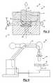
- FIG. 4illustrates the riveting apparatus of FIGS. 1, 2 and 3 with a robot arm and an energy source
- FIG. 5 ( a )illustrates a side sectional view of an exemplary rivet
- FIG. 5 ( b )illustrates a bottom sectional view of the rivet of FIG. 5 ( a ) taken along line 5 B— 5 B;
- FIG. 6 ( a )illustrates a side sectional view of another exemplary rivet
- FIG. 6 ( b )illustrates a bottom sectional view of the rivet of FIG. 6 ( a ) taken along line 6 B— 6 B.
- a first metal member(depicted as a sheet 10 ) is riveted to a second metal member (also depicted as a sheet 12 ) with a piercing rivet 14 that is driven into the sheets 10 , 12 by a riveting apparatus 16 .
- the riveting apparatus 16includes a rivet driving assembly 18 for driving the rivet 14 through the first sheet 10 and into the second sheet 12 and a die 22 for supporting the metal sheets 10 , 12 and for assisting in securing the rivet 14 to the sheets 10 , 12 .
- the rivet assembly 18includes a clamp 24 (e.g., a generally elongated metal binder clamp) having an opening 26 extending down at least a portion of a length of the clamp 24 .
- a punch 28e.g., an elongated cylindrical steel punch
- the punch 28may be moved hydraulically, mechanically, electrically, pneumatically or otherwise.
- the punch 28 , the opening 26 and the binder clamp 24are generally cylindrical, coaxial or both about an axis 38 extending centrally along their lengths.
- a housing(not shown) can be used to house or fasten the binder clamp 24 and the punch 28 together.
- other conventional fasteners or fastening techniquesmay be used.
- the die 22includes a central cylindrical opening or cavity 46 defined by a bottom circular surface 48 and a peripheral annular wall surface 50 , which may be integrated into a single continuous surface.
- the die 22includes a protrusion 52 that extends into the cavity 46 from the center of the circular surface 48 .
- the die 22may be formed in a variety of sizes or with a variety of cavity shapes depending upon the rivet 14 to be driven into the sheets 10 , 12 , the properties of the sheets 10 , 12 , the thickness of the sheets or a combination thereof.
- the die 22is supported by tooling, a stand or the like.
- the rivet assembly 18 , the die 22 or bothmay be mounted to various apparatus for moving the rivet assembly 18 or the die 22 relative to each other, such as robots, C-frames or hard tooling such as a die set.
- the rivet assembly 18is attached to a robot arm 60 that can move the rivet assembly 18 as needed or desired.
- the die 22is positioned adjacent the robot arm 60 .
- a piercing rivet 14that is substantially symmetrical about a central axis 68 and includes a head portion 70 and a body portion 72 with a sharpened edge portion 74 , that is adapted to both pierce a material and deform during piercing for forming an interlock.
- the head portion 70is generally disk-shaped with a substantially flat top surface 76 and a generally conical bottom surface 78 .
- the body portion 72is generally annular and extends outwardly away from the bottom surface 78 of the head portion 70 .
- the head portion 70extends radially outwardly away from the central axis 68 further than the body portion 72 .
- the body portion 72includes an inner annular surface 80 and an outer annular surface 82 .
- the inner annular surface 80at least partially defines a central substantially cylindrical cavity 84 within the rivet 14 .
- the body portion 72includes a plurality of passages 88 extending radially away from the central axis 68 and extending from the inner surface 80 to the outer surface 82 .
- the rivet 14may be formed of a variety of high strength to weight metals such as aluminum or magnesium alloys. Preferably, however, the rivet 14 is formed of a mild or high strength steel.
- the rivet 14may be coated with a suitable protective coating, such as an anti-corrosion agent, or may be selectively hardened at certain portions for achieving a hardness gradient in the rivet.
- An amount of adhesive 90is disposed within the cavity 84 for assisting the rivet 14 to securely join the sheets 10 , 12 together as further described below.
- the adhesive 90is epoxy-based and has the ability to adhere securely to one or more metals.
- the adhesive 90is generally flowable at temperatures typically experienced in an automotive assembly plant (e.g., about 10° C. to about 40° C.) and cures to a hardened state at elevated temperatures (e.g., about greater than 100° C.).
- One example of a commercially available adhesiveis sold under the tradename BETAMATE 4601 and is commercially available from the Dow Chemical Corporation, Midland, Mich.
- the piercing rivet 14is positioned within the rivet assembly 18 for allowing the punch 28 to drive the rivet 14 into the sheets 10 , 12 .
- the top surface 76 of the rivet 14is contacted substantially flush against the punch 28 .
- the rivet 14may be temporarily secured against the punch 28 , such as by magnetic forces, with a securing member (not shown) or otherwise.
- the first metal sheet 10 and second metal sheet 12each include a first side 100 and a second side 102 .
- the first sheet 10is stacked upon the second sheet 12 such that at least a portion of the second side 102 of the first sheet 10 is in substantially continuous contact with at least a portion of the first side 100 of the second sheet 12 to form an overlapping portion or region for receiving the rivet 14 .
- the sheets 10 , 12may be formed of the same or different of several metals.
- the sheets 10 , 12are formed of metal alloys of aluminum, magnesium, steel of various strengths or the like with thicknesses ranging between 0.6 mm and 3.0 mm, although thicker of thinner sheets may also be used.
- the stacked sheets 10 , 12are placed between the rivet assembly 18 and the die 22 of the riveting apparatus 14 .
- the sheets 10 , 12are placed upon the die 22 such that the second side 102 of the second sheet 12 contacts the die 22 .
- the rivet assembly 18is contacted with first side 100 of the first sheet 10 (e.g., using the robot arm 60 or another apparatus) to clamp the sheets 10 , 12 between the rivet assembly 18 and the die 22 .
- the punch 28is moved from its first position shown in FIG. 1 to its second position as shown in FIG. 3 to drive the rivet 14 at least partially through the overlapping region of the sheets 10 , 12 .
- the sharpened piercing edge 74 of the rivet 14pierces entirely through the first sheet 10 and partially through the second sheet 12 .
- the rivet 14urges a portion 120 of the first and second sheets 10 , 12 into contact with the protrusion 52 of the die 22 thereby pinching the portion 120 between the rivet 14 and the protrusion 52 .
- the protrusion 52places a force on the portion 120 of the sheet 10 , 12 and the force is transmitted to the annular portion 72 of the rivet 14 .
- This forceat least partially bends or deforms the annular portion 72 , starting with the sharpened edge 74 , radially away from the central axis 68 of rivet 14 to interferingly secure the rivet 14 to the sheets 10 , 12 thereby attaching the sheets 10 , 12 to each other.
- the rivet 14is driven through the first sheet 10 and into the second sheet 12 until the top surface 76 of the head portion 70 is substantially flush with the first surface 100 of the first sheet 10 .
- the portion 120 of the sheets 10 , 12 that contacts the protrusion 52 of the die 22is pushed into the cavity 84 of the rivet 14 thereby forcing the adhesive 90 out of the cavity 84 .
- the adhesive 90is either forced through the passages 88 of the rivet 14 , around the sharpened edge 74 of the rivet 14 or both thereby positioning the adhesive 90 between the outer annular surface 82 of the rivet 14 and portions of the first sheet 10 , the second sheet 12 or both.
- the adhesive 90may also be at least partially sandwiched between the second surface 102 of the first sheet 10 and the first surface 100 of the second sheet 12 .
- the adhesive 90is cured to more securely attach the rivet 14 to the sheets 10 , 12 and to more securely attach the sheets 10 , 12 to each other.
- the adhesive 90cures after exposure to elevated temperatures of about 130° C. to about 220° C., and more preferably temperatures of about 160° C. to about 180° C. and most preferably about 170° C. Cure times may range, but are preferably less than 60 minutes, more preferably between about 20 and 40 minutes and most preferably about 25 minutes. Such time lengths and elevated temperatures are typically encountered during a baking cycle during painting of the automotive vehicle.
- riveting of the sheets 10 , 12 while simultaneously adhesively securing the rivet 14 to the sheets 10 , 12fastens the rivet 14 more securely to the sheets 10 , 12 thereby more securely fastening the sheets 10 , 12 together.
- FIGS. 6 ( a ) and 6 ( b )there is illustrated an alternative rivet 14 substantially identical to the rivet 14 of FIGS. 5 ( a ) and 5 ( b ) with the exception that a plurality of channels 110 have been defined within the inner annular surface 80 .
- each of the channels 110extends from adjacent the bottom surface 78 of the head portion 70 of the rivet 14 to one of the plurality of passages 88 .
- the channels 110assist the adhesive 90 to flow through the passages 88 toward the outer annular surface 82 of the rivet 14 .
- the overlapped region of the sheets 10 , 12 into which the rivet 14 is drivenmay be heated prior to driving the rivet 14 through the sheets 10 , 12 .
- an electric currentmay be passed through the sheets 10 , 12 according to methods such as those disclosed in commonly owned copending application titled “A Method and Apparatus for Riveting Metal Sheets”, U.S. Ser. No. 10/094,128 filed on the same date as the present application and fully incorporated herein by reference for all purposes.
- the rivet and method described abovemay be used for attaching several different automotive components that have sheet metal or sheet metal portions. Resulting joints are also considered part of the present invention. Examples include peel joints, lap joints, various vehicle panels such as body panels, door panels, decklids, hoods, door frames, sunroof applications or the like. Furthermore, the overlapped regions of the sheets may be continuously bonded or intermittently bonded over some or all of its area.
Landscapes
- Engineering & Computer Science (AREA)
- Mechanical Engineering (AREA)
- General Engineering & Computer Science (AREA)
- Connection Of Plates (AREA)
- Insertion Pins And Rivets (AREA)
Abstract
Description
Claims (14)
Priority Applications (2)
| Application Number | Priority Date | Filing Date | Title |
|---|---|---|---|
| US10/094,073US6732420B2 (en) | 2002-03-08 | 2002-03-08 | Method for riveting metal members therewith |
| US10/797,954US6962469B2 (en) | 2002-03-08 | 2004-03-11 | Adhesive dispersing rivet |
Applications Claiming Priority (1)
| Application Number | Priority Date | Filing Date | Title |
|---|---|---|---|
| US10/094,073US6732420B2 (en) | 2002-03-08 | 2002-03-08 | Method for riveting metal members therewith |
Related Child Applications (1)
| Application Number | Title | Priority Date | Filing Date |
|---|---|---|---|
| US10/797,954DivisionUS6962469B2 (en) | 2002-03-08 | 2004-03-11 | Adhesive dispersing rivet |
Publications (2)
| Publication Number | Publication Date |
|---|---|
| US20030167620A1 US20030167620A1 (en) | 2003-09-11 |
| US6732420B2true US6732420B2 (en) | 2004-05-11 |
Family
ID=27788058
Family Applications (2)
| Application Number | Title | Priority Date | Filing Date |
|---|---|---|---|
| US10/094,073Expired - Fee RelatedUS6732420B2 (en) | 2002-03-08 | 2002-03-08 | Method for riveting metal members therewith |
| US10/797,954Expired - Fee RelatedUS6962469B2 (en) | 2002-03-08 | 2004-03-11 | Adhesive dispersing rivet |
Family Applications After (1)
| Application Number | Title | Priority Date | Filing Date |
|---|---|---|---|
| US10/797,954Expired - Fee RelatedUS6962469B2 (en) | 2002-03-08 | 2004-03-11 | Adhesive dispersing rivet |
Country Status (1)
| Country | Link |
|---|---|
| US (2) | US6732420B2 (en) |
Cited By (23)
| Publication number | Priority date | Publication date | Assignee | Title |
|---|---|---|---|---|
| US20040156697A1 (en)* | 2001-10-09 | 2004-08-12 | Ray Bailey | Adapter for hanger bolts |
| US20040194284A1 (en)* | 2003-04-07 | 2004-10-07 | Pei-Chung Wang | Adhesive encapsulated blind rivet system |
| US20040216290A1 (en)* | 2003-03-03 | 2004-11-04 | Siemens Aktiengesellschaft | Electric drive for a shaping die |
| US20040218990A1 (en)* | 2003-04-29 | 2004-11-04 | Robin Stevenson | Blind rivet with adhesive for joining and adhesive charging method |
| US20050111911A1 (en)* | 2003-11-21 | 2005-05-26 | Srecko Zdravkovic | Self-piercing fastening system |
| US20060098135A1 (en)* | 2004-10-26 | 2006-05-11 | Samsung Sdi Co., Ltd. | Method for joining plates, plate joining structure, and display module having the same |
| US20080163728A1 (en)* | 2007-01-05 | 2008-07-10 | Snap-On Incorporated | Dual hardness connector |
| US20100018027A1 (en)* | 2008-07-28 | 2010-01-28 | Robin Stevenson | Method of joining with self-piercing rivet and assembly |
| US20100088880A1 (en)* | 2008-10-09 | 2010-04-15 | Gm Global Technology Operations, Inc. | Self-piercing rivet and method of joining with bonded riveted joints |
| US20120124816A1 (en)* | 2010-11-23 | 2012-05-24 | Gm Global Technology Operations, Inc. | Joining magnesium with reinforced polymer composite fasteners |
| US20120180305A1 (en)* | 2009-08-24 | 2012-07-19 | Newfrey Llc | Punch rivet, method for producing a punch rivet connection, and workpiece arrangement |
| US20130074312A1 (en)* | 2011-09-23 | 2013-03-28 | GM Global Technology Operations LLC | Method of joining magnesium |
| CN103084531A (en)* | 2013-01-22 | 2013-05-08 | 昆明理工大学 | Assistant positioning method for self-piercing riveting |
| US20150290914A1 (en)* | 2014-04-10 | 2015-10-15 | Ford Global Technologies, Llc | Process For Joining Carbon Fiber Composite Materials Using Self-Piercing Rivets |
| US20160167320A1 (en)* | 2014-12-10 | 2016-06-16 | Hyundai Motor Company | Self-piercing rivet |
| DE102015102174A1 (en)* | 2015-02-16 | 2016-08-18 | Newfrey Llc | Punch rivet and method of making a riveted joint |
| US20160281757A1 (en)* | 2013-12-11 | 2016-09-29 | Newfrey Llc | Self-piercing rivet and self-piercing riveting method and self-piercing riveted joint |
| US20170113738A1 (en)* | 2014-06-27 | 2017-04-27 | Ford Global Technologies, Llc | Method of fastening vehicle parts |
| CN107297909A (en)* | 2016-04-14 | 2017-10-27 | 通用汽车环球科技运作有限责任公司 | Method for joining polymer composites and other materials using self-tapping rivets |
| US20180272649A1 (en)* | 2015-01-09 | 2018-09-27 | Christopher Booth-Morrison | Multi-Layer NPR Structures |
| US10400813B2 (en) | 2012-06-11 | 2019-09-03 | Board Of Trustees Of Michigan State University | Hybrid fastener |
| US10456850B2 (en) | 2013-04-19 | 2019-10-29 | Magna International Inc. | Joining of dissimilar materials |
| US11076530B2 (en) | 2019-03-15 | 2021-08-03 | Honda Motor Co., Ltd. | Riveted joint and method of forming the same |
Families Citing this family (25)
| Publication number | Priority date | Publication date | Assignee | Title |
|---|---|---|---|---|
| US7284319B2 (en)* | 2002-02-08 | 2007-10-23 | Newfrey Llc | Self-piercing rivet setting die and apparatus |
| JP2006021220A (en)* | 2004-07-07 | 2006-01-26 | Nippon Pop Rivets & Fasteners Ltd | Self-boring type rivet fastening apparatus |
| US7380326B2 (en)* | 2005-11-02 | 2008-06-03 | Whitesell International Corporation | Method of attaching a self-attaching fastener to a panel |
| US20100083481A1 (en)* | 2008-10-08 | 2010-04-08 | Gm Global Technology Operations, Inc. | Method for attaching magnesium panels using self-piercing rivet |
| DE102010024000A1 (en)* | 2010-06-16 | 2011-12-22 | Ruia Global Fasteners Ag | Method and device for setting non-cutting self-perforating fasteners |
| DE102012008798B4 (en)* | 2012-03-31 | 2016-01-14 | Johnson Controls Gmbh | Method of joining and connecting element |
| DE102012011020A1 (en)* | 2012-06-05 | 2013-12-05 | Newfrey Llc | Punch rivet, rivet connection and riveting method |
| DE102012013829B4 (en)* | 2012-07-13 | 2024-03-14 | Newfrey Llc | Punch rivet die, punch rivet tool and punch rivet process |
| DE102014000623B4 (en) | 2014-01-18 | 2018-09-27 | Audi Ag | Halbhohlnietelement |
| DE102014218193A1 (en) | 2014-09-11 | 2016-03-17 | Volkswagen Aktiengesellschaft | Expandable connecting element for joining at least two parts to be joined |
| US20160169264A1 (en)* | 2014-12-10 | 2016-06-16 | Newfrey Llc | Cage stud assembly and related assembly methods |
| DE102015112770A1 (en)* | 2015-08-04 | 2017-02-09 | Thyssenkrupp Ag | Joining with Joining Joining Elements |
| DE102016201795B4 (en) | 2016-02-05 | 2021-07-22 | Volkswagen Aktiengesellschaft | Method for joining at least two parts to be joined |
| US11028865B2 (en) | 2016-12-02 | 2021-06-08 | Magna International Inc. | Method of attaching sheets together |
| KR102529491B1 (en)* | 2016-12-22 | 2023-05-04 | 현대자동차주식회사 | A friction rivet for joining different materials |
| US10590979B2 (en) | 2017-01-24 | 2020-03-17 | Ford Global Technologies, Llc | Corrosion protection for mechanical joints |
| CN110382133B (en) | 2017-03-03 | 2022-01-21 | 尤蒂卡企业公司 | Apparatus and method for securing clinch nuts to advanced high strength steel panels and resulting assemblies |
| JP7398186B2 (en)* | 2018-05-10 | 2023-12-14 | 日産自動車株式会社 | Board joining structure and joining method |
| CN108555219B (en)* | 2018-05-14 | 2019-12-31 | 上海应用技术大学 | Self-piercing riveting device and self-piercing riveting method for semi-hollow rivets |
| DE102018114982A1 (en) | 2018-06-21 | 2019-12-24 | Ejot Gmbh & Co. Kg | Connecting element and component connection, and method for producing the same |
| CN109047627B (en)* | 2018-07-26 | 2023-11-03 | 江苏海迪威液压有限公司 | Silver sheet conveying device for silver riveting point machine |
| GB201812641D0 (en)* | 2018-08-03 | 2018-09-19 | Henrob Ltd | Riveting method |
| CN114233733B (en)* | 2021-11-12 | 2022-11-01 | 上海交通大学 | Improved structural rivet for forming flat bottom rivet of sheet material |
| CN114652057B (en)* | 2022-04-12 | 2023-11-28 | 深圳市联星服装辅料有限公司 | slingshot button |
| WO2024086467A1 (en) | 2022-10-18 | 2024-04-25 | Martinrea International US Inc. | Assembly and process for forming an edge clinching of overlapping panels |
Citations (6)
| Publication number | Priority date | Publication date | Assignee | Title |
|---|---|---|---|---|
| US3434743A (en)* | 1966-07-07 | 1969-03-25 | Fmc Corp | Well apparatus |
| US3639137A (en)* | 1969-10-09 | 1972-02-01 | Ncr Co | Metal fastening coated with pressure-activatable encapsulated sealant system |
| WO1998001679A1 (en) | 1996-07-04 | 1998-01-15 | Textron Fastening Systems Limited | Self-piercing riveting |
| US5752305A (en) | 1992-12-19 | 1998-05-19 | Henrob Limited | Self-piercing riveting method and apparatus |
| JPH1133664A (en) | 1997-07-10 | 1999-02-09 | Kobe Steel Ltd | Aluminum alloy joined body by self-piercing rivet, and its manufacture |
| US5957777A (en) | 1997-07-04 | 1999-09-28 | Rivet Technology ( P) Ltd. | Method of manufacturing fasteners |
Family Cites Families (11)
| Publication number | Priority date | Publication date | Assignee | Title |
|---|---|---|---|---|
| US180747A (en)* | 1876-08-08 | Improvement in rivets | ||
| US3772957A (en)* | 1972-05-22 | 1973-11-20 | Usm Corp | Self-drilling and sealing rivet |
| US4055051A (en)* | 1976-01-08 | 1977-10-25 | The United States Of America As Represented By The Secretary Of The Interior | Unitary drill bit and roof bolt |
| US4693652A (en)* | 1978-08-24 | 1987-09-15 | Theodore Sweeney & Company, Inc. | Adhesively securable fastener |
| US5044852B1 (en)* | 1978-08-24 | 1995-04-04 | Sweeney Theodore Co | Vacuum fixed adhesively secured fastener |
| DE3437186A1 (en)* | 1984-10-10 | 1986-04-10 | Fischer, Artur, Dr.H.C., 7244 Waldachtal | PLASTIC DOWELS, IN PARTICULAR FOR FASTENING ON TILED WALLPAPER PLASTERBOARD WALLS |
| US4820095A (en)* | 1988-02-26 | 1989-04-11 | Engineered Instruments, Inc. | Anchor device for securing rock bolts |
| US5145301A (en)* | 1991-02-13 | 1992-09-08 | Akio Yamamoto | Nail sustainer |
| US5253965A (en)* | 1992-04-13 | 1993-10-19 | Progressive Tool & Industries Co. | Piercing fastener with adhesive |
| DE4333052C2 (en)* | 1993-09-29 | 2002-01-24 | Audi Ag | Self-punching fastening device |
| DE10017750B4 (en)* | 2000-04-10 | 2008-11-20 | Hilti Aktiengesellschaft | rock bolts |
- 2002
- 2002-03-08USUS10/094,073patent/US6732420B2/ennot_activeExpired - Fee Related
- 2004
- 2004-03-11USUS10/797,954patent/US6962469B2/ennot_activeExpired - Fee Related
Patent Citations (6)
| Publication number | Priority date | Publication date | Assignee | Title |
|---|---|---|---|---|
| US3434743A (en)* | 1966-07-07 | 1969-03-25 | Fmc Corp | Well apparatus |
| US3639137A (en)* | 1969-10-09 | 1972-02-01 | Ncr Co | Metal fastening coated with pressure-activatable encapsulated sealant system |
| US5752305A (en) | 1992-12-19 | 1998-05-19 | Henrob Limited | Self-piercing riveting method and apparatus |
| WO1998001679A1 (en) | 1996-07-04 | 1998-01-15 | Textron Fastening Systems Limited | Self-piercing riveting |
| US5957777A (en) | 1997-07-04 | 1999-09-28 | Rivet Technology ( P) Ltd. | Method of manufacturing fasteners |
| JPH1133664A (en) | 1997-07-10 | 1999-02-09 | Kobe Steel Ltd | Aluminum alloy joined body by self-piercing rivet, and its manufacture |
Cited By (42)
| Publication number | Priority date | Publication date | Assignee | Title |
|---|---|---|---|---|
| US20040156697A1 (en)* | 2001-10-09 | 2004-08-12 | Ray Bailey | Adapter for hanger bolts |
| US20040216290A1 (en)* | 2003-03-03 | 2004-11-04 | Siemens Aktiengesellschaft | Electric drive for a shaping die |
| US7313861B2 (en)* | 2003-03-03 | 2008-01-01 | Siemens Aktiengesellschaft | Electric drive for a shaping die |
| US20040194284A1 (en)* | 2003-04-07 | 2004-10-07 | Pei-Chung Wang | Adhesive encapsulated blind rivet system |
| US7017255B2 (en)* | 2003-04-07 | 2006-03-28 | General Motors Corporation | Adhesive encapsulated blind rivet system |
| US20040218990A1 (en)* | 2003-04-29 | 2004-11-04 | Robin Stevenson | Blind rivet with adhesive for joining and adhesive charging method |
| US6868597B2 (en)* | 2003-04-29 | 2005-03-22 | General Motors Corporation | Blind rivet with adhesive for joining and adhesive charging method |
| US20050111911A1 (en)* | 2003-11-21 | 2005-05-26 | Srecko Zdravkovic | Self-piercing fastening system |
| US7032296B2 (en)* | 2003-11-21 | 2006-04-25 | Newfrey Llc | Self-piercing fastening system |
| US7595977B2 (en)* | 2004-10-26 | 2009-09-29 | Samsung Sdi Co., Ltd. | Method for joining plates, plate joining structure, and display module having the same |
| US20060098135A1 (en)* | 2004-10-26 | 2006-05-11 | Samsung Sdi Co., Ltd. | Method for joining plates, plate joining structure, and display module having the same |
| US20080163728A1 (en)* | 2007-01-05 | 2008-07-10 | Snap-On Incorporated | Dual hardness connector |
| US20090067949A1 (en)* | 2007-01-05 | 2009-03-12 | Snap-On Incorporated | Dual hardness connector |
| US20100018027A1 (en)* | 2008-07-28 | 2010-01-28 | Robin Stevenson | Method of joining with self-piercing rivet and assembly |
| US8250728B2 (en) | 2008-07-28 | 2012-08-28 | GM Global Technology Operations LLC | Method of joining with self-piercing rivet and assembly |
| US20100088880A1 (en)* | 2008-10-09 | 2010-04-15 | Gm Global Technology Operations, Inc. | Self-piercing rivet and method of joining with bonded riveted joints |
| US8087149B2 (en) | 2008-10-09 | 2012-01-03 | GM Global Technology Operations LLC | Self-piercing rivet and method of joining with bonded riveted joints |
| US20120180305A1 (en)* | 2009-08-24 | 2012-07-19 | Newfrey Llc | Punch rivet, method for producing a punch rivet connection, and workpiece arrangement |
| US8763233B2 (en)* | 2009-08-24 | 2014-07-01 | Newfrey Llc | Punch rivet, method for producing a punch rivet connection, and workpiece arrangement |
| US20120124816A1 (en)* | 2010-11-23 | 2012-05-24 | Gm Global Technology Operations, Inc. | Joining magnesium with reinforced polymer composite fasteners |
| US8448324B2 (en)* | 2010-11-23 | 2013-05-28 | GM Global Technology Operations LLC | Joining magnesium with reinforced polymer composite fasteners |
| CN103016477A (en)* | 2011-09-23 | 2013-04-03 | 通用汽车环球科技运作有限责任公司 | Method of joining magnesium |
| US20130074312A1 (en)* | 2011-09-23 | 2013-03-28 | GM Global Technology Operations LLC | Method of joining magnesium |
| US8966734B2 (en)* | 2011-09-23 | 2015-03-03 | GM Global Technology Operations LLC | Method of joining magnesium |
| CN103016477B (en)* | 2011-09-23 | 2015-03-18 | 通用汽车环球科技运作有限责任公司 | Method of joining magnesium |
| US10400813B2 (en) | 2012-06-11 | 2019-09-03 | Board Of Trustees Of Michigan State University | Hybrid fastener |
| CN103084531A (en)* | 2013-01-22 | 2013-05-08 | 昆明理工大学 | Assistant positioning method for self-piercing riveting |
| US10456850B2 (en) | 2013-04-19 | 2019-10-29 | Magna International Inc. | Joining of dissimilar materials |
| US10465730B2 (en) | 2013-12-11 | 2019-11-05 | Newfrey Llc | Self-piercing rivet and self-piercing riveting method and self-piercing riveted joint |
| US10550873B2 (en) | 2013-12-11 | 2020-02-04 | Newfrey Llc | Self-piercing rivet and self-piercing riveting method and self-piercing riveted joint |
| US11333187B2 (en) | 2013-12-11 | 2022-05-17 | Newfrey Llc | Self-piercing rivet and self-piercing riveting method and self-piercing riveted joint |
| US20160281757A1 (en)* | 2013-12-11 | 2016-09-29 | Newfrey Llc | Self-piercing rivet and self-piercing riveting method and self-piercing riveted joint |
| US9803675B2 (en)* | 2013-12-11 | 2017-10-31 | Newfrey Llc | Self-piercing rivet and self-piercing riveting method and self-piercing riveted joint |
| US20150290914A1 (en)* | 2014-04-10 | 2015-10-15 | Ford Global Technologies, Llc | Process For Joining Carbon Fiber Composite Materials Using Self-Piercing Rivets |
| US10704584B2 (en) | 2014-04-10 | 2020-07-07 | Ford Global Technologies, Llc | Process for joining fiber composite materials using self-piercing rivets |
| US10286962B2 (en)* | 2014-06-27 | 2019-05-14 | Ford Global Technologies, Llc | Method of fastening vehicle parts |
| US20170113738A1 (en)* | 2014-06-27 | 2017-04-27 | Ford Global Technologies, Llc | Method of fastening vehicle parts |
| US20160167320A1 (en)* | 2014-12-10 | 2016-06-16 | Hyundai Motor Company | Self-piercing rivet |
| US20180272649A1 (en)* | 2015-01-09 | 2018-09-27 | Christopher Booth-Morrison | Multi-Layer NPR Structures |
| DE102015102174A1 (en)* | 2015-02-16 | 2016-08-18 | Newfrey Llc | Punch rivet and method of making a riveted joint |
| CN107297909A (en)* | 2016-04-14 | 2017-10-27 | 通用汽车环球科技运作有限责任公司 | Method for joining polymer composites and other materials using self-tapping rivets |
| US11076530B2 (en) | 2019-03-15 | 2021-08-03 | Honda Motor Co., Ltd. | Riveted joint and method of forming the same |
Also Published As
| Publication number | Publication date |
|---|---|
| US6962469B2 (en) | 2005-11-08 |
| US20040170490A1 (en) | 2004-09-02 |
| US20030167620A1 (en) | 2003-09-11 |
Similar Documents
| Publication | Publication Date | Title |
|---|---|---|
| US6732420B2 (en) | Method for riveting metal members therewith | |
| US6694597B2 (en) | Method for riveting metal members | |
| US20080149256A1 (en) | Method and apparatus to minimize adhesive induced distortion | |
| EP3026273A1 (en) | Rivet for connecting different materials, member for connecting different materials, method for manufacturing joined body of different materials, and joined body of different materials | |
| EP0614405B1 (en) | Improved panel clinching methods | |
| JP2018171658A (en) | Resistance welding fastener, apparatus, and method | |
| US20160158873A1 (en) | Method for connecting at least two sheet metal parts | |
| US7422652B2 (en) | Method of making a body panel assembly | |
| US6659567B2 (en) | Wheel balance weight and process for manufacturing the same | |
| JP2006007266A (en) | Joining method using rivets | |
| JP6108656B2 (en) | Method for manufacturing joint of dissimilar metals | |
| US7017255B2 (en) | Adhesive encapsulated blind rivet system | |
| US11143227B2 (en) | Component combination of at least two components and a method for producing a component combination joined in a form-fitting and/or force-fitting manner | |
| JP5724568B2 (en) | Metal member joint and method of manufacturing the same | |
| JP7410398B2 (en) | Manufacturing method of riveted joint structure, riveted joint structure and automobile parts | |
| WO2021200736A1 (en) | Method for manufacturing contact joint structure, contact joint structure, and automotive part | |
| US6842962B1 (en) | Sheet joining method and apparatus and a rivet for use in the method | |
| US10974462B2 (en) | Fastener and method for joining dissimilar materials | |
| JP5973817B2 (en) | Fastening structure and automobile | |
| JPH0796571A (en) | Structural panel | |
| JPS62148036A (en) | Joining device for thin metallic plate | |
| JP7456403B2 (en) | molding sealer | |
| JP2021154377A (en) | Method for manufacturing rivet joint structure, rivet joint structure and automobile components | |
| JP2008221947A (en) | Vehicle body joining method and its joining structure | |
| CN111356609A (en) | Joint body and seat frame for automobile |
Legal Events
| Date | Code | Title | Description |
|---|---|---|---|
| AS | Assignment | Owner name:GENERAL MOTORS CORPORATION, MICHIGAN Free format text:ASSIGNMENT OF ASSIGNORS INTEREST;ASSIGNORS:WANG, PEI-CHUNG;HAYDEN, DANIEL B.;STEVENSON, ROBIN;REEL/FRAME:012876/0140;SIGNING DATES FROM 20020211 TO 20020221 | |
| FPAY | Fee payment | Year of fee payment:4 | |
| AS | Assignment | Owner name:GM GLOBAL TECHNOLOGY OPERATIONS, INC., MICHIGAN Free format text:ASSIGNMENT OF ASSIGNORS INTEREST;ASSIGNOR:GENERAL MOTORS CORPORATION;REEL/FRAME:022117/0047 Effective date:20050119 Owner name:GM GLOBAL TECHNOLOGY OPERATIONS, INC.,MICHIGAN Free format text:ASSIGNMENT OF ASSIGNORS INTEREST;ASSIGNOR:GENERAL MOTORS CORPORATION;REEL/FRAME:022117/0047 Effective date:20050119 | |
| AS | Assignment | Owner name:UNITED STATES DEPARTMENT OF THE TREASURY, DISTRICT Free format text:SECURITY AGREEMENT;ASSIGNOR:GM GLOBAL TECHNOLOGY OPERATIONS, INC.;REEL/FRAME:022201/0547 Effective date:20081231 Owner name:UNITED STATES DEPARTMENT OF THE TREASURY,DISTRICT Free format text:SECURITY AGREEMENT;ASSIGNOR:GM GLOBAL TECHNOLOGY OPERATIONS, INC.;REEL/FRAME:022201/0547 Effective date:20081231 | |
| AS | Assignment | Owner name:CITICORP USA, INC. AS AGENT FOR BANK PRIORITY SECU Free format text:SECURITY AGREEMENT;ASSIGNOR:GM GLOBAL TECHNOLOGY OPERATIONS, INC.;REEL/FRAME:022553/0399 Effective date:20090409 Owner name:CITICORP USA, INC. AS AGENT FOR HEDGE PRIORITY SEC Free format text:SECURITY AGREEMENT;ASSIGNOR:GM GLOBAL TECHNOLOGY OPERATIONS, INC.;REEL/FRAME:022553/0399 Effective date:20090409 | |
| AS | Assignment | Owner name:GM GLOBAL TECHNOLOGY OPERATIONS, INC., MICHIGAN Free format text:RELEASE BY SECURED PARTY;ASSIGNOR:UNITED STATES DEPARTMENT OF THE TREASURY;REEL/FRAME:023124/0470 Effective date:20090709 Owner name:GM GLOBAL TECHNOLOGY OPERATIONS, INC.,MICHIGAN Free format text:RELEASE BY SECURED PARTY;ASSIGNOR:UNITED STATES DEPARTMENT OF THE TREASURY;REEL/FRAME:023124/0470 Effective date:20090709 | |
| AS | Assignment | Owner name:GM GLOBAL TECHNOLOGY OPERATIONS, INC., MICHIGAN Free format text:RELEASE BY SECURED PARTY;ASSIGNORS:CITICORP USA, INC. AS AGENT FOR BANK PRIORITY SECURED PARTIES;CITICORP USA, INC. AS AGENT FOR HEDGE PRIORITY SECURED PARTIES;REEL/FRAME:023127/0273 Effective date:20090814 Owner name:GM GLOBAL TECHNOLOGY OPERATIONS, INC.,MICHIGAN Free format text:RELEASE BY SECURED PARTY;ASSIGNORS:CITICORP USA, INC. AS AGENT FOR BANK PRIORITY SECURED PARTIES;CITICORP USA, INC. AS AGENT FOR HEDGE PRIORITY SECURED PARTIES;REEL/FRAME:023127/0273 Effective date:20090814 | |
| AS | Assignment | Owner name:UNITED STATES DEPARTMENT OF THE TREASURY, DISTRICT Free format text:SECURITY AGREEMENT;ASSIGNOR:GM GLOBAL TECHNOLOGY OPERATIONS, INC.;REEL/FRAME:023156/0001 Effective date:20090710 Owner name:UNITED STATES DEPARTMENT OF THE TREASURY,DISTRICT Free format text:SECURITY AGREEMENT;ASSIGNOR:GM GLOBAL TECHNOLOGY OPERATIONS, INC.;REEL/FRAME:023156/0001 Effective date:20090710 | |
| AS | Assignment | Owner name:UAW RETIREE MEDICAL BENEFITS TRUST, MICHIGAN Free format text:SECURITY AGREEMENT;ASSIGNOR:GM GLOBAL TECHNOLOGY OPERATIONS, INC.;REEL/FRAME:023161/0911 Effective date:20090710 Owner name:UAW RETIREE MEDICAL BENEFITS TRUST,MICHIGAN Free format text:SECURITY AGREEMENT;ASSIGNOR:GM GLOBAL TECHNOLOGY OPERATIONS, INC.;REEL/FRAME:023161/0911 Effective date:20090710 | |
| AS | Assignment | Owner name:GM GLOBAL TECHNOLOGY OPERATIONS, INC., MICHIGAN Free format text:RELEASE BY SECURED PARTY;ASSIGNOR:UAW RETIREE MEDICAL BENEFITS TRUST;REEL/FRAME:025311/0680 Effective date:20101026 Owner name:GM GLOBAL TECHNOLOGY OPERATIONS, INC., MICHIGAN Free format text:RELEASE BY SECURED PARTY;ASSIGNOR:UNITED STATES DEPARTMENT OF THE TREASURY;REEL/FRAME:025245/0273 Effective date:20100420 | |
| AS | Assignment | Owner name:WILMINGTON TRUST COMPANY, DELAWARE Free format text:SECURITY AGREEMENT;ASSIGNOR:GM GLOBAL TECHNOLOGY OPERATIONS, INC.;REEL/FRAME:025327/0222 Effective date:20101027 | |
| AS | Assignment | Owner name:GM GLOBAL TECHNOLOGY OPERATIONS LLC, MICHIGAN Free format text:CHANGE OF NAME;ASSIGNOR:GM GLOBAL TECHNOLOGY OPERATIONS, INC.;REEL/FRAME:025780/0795 Effective date:20101202 | |
| FPAY | Fee payment | Year of fee payment:8 | |
| AS | Assignment | Owner name:GM GLOBAL TECHNOLOGY OPERATIONS LLC, MICHIGAN Free format text:RELEASE BY SECURED PARTY;ASSIGNOR:WILMINGTON TRUST COMPANY;REEL/FRAME:034183/0680 Effective date:20141017 | |
| REMI | Maintenance fee reminder mailed | ||
| LAPS | Lapse for failure to pay maintenance fees | ||
| STCH | Information on status: patent discontinuation | Free format text:PATENT EXPIRED DUE TO NONPAYMENT OF MAINTENANCE FEES UNDER 37 CFR 1.362 | |
| FP | Lapsed due to failure to pay maintenance fee | Effective date:20160511 |