US6731613B1 - Power management using a bandwidth control mechanism - Google Patents
Power management using a bandwidth control mechanismDownload PDFInfo
- Publication number
- US6731613B1 US6731613B1US09/594,617US59461700AUS6731613B1US 6731613 B1US6731613 B1US 6731613B1US 59461700 AUS59461700 AUS 59461700AUS 6731613 B1US6731613 B1US 6731613B1
- Authority
- US
- United States
- Prior art keywords
- switching network
- network component
- packet switching
- packet
- buffered
- Prior art date
- Legal status (The legal status is an assumption and is not a legal conclusion. Google has not performed a legal analysis and makes no representation as to the accuracy of the status listed.)
- Expired - Lifetime, expires
Links
- 230000007246mechanismEffects0.000titleclaimsabstractdescription24
- 238000004891communicationMethods0.000claimsabstractdescription65
- 239000000872bufferSubstances0.000claimsabstractdescription32
- 230000007704transitionEffects0.000claimsabstractdescription27
- 230000004044responseEffects0.000claimsabstractdescription18
- 238000000034methodMethods0.000claimsdescription15
- 230000008859changeEffects0.000claimsdescription4
- 238000001514detection methodMethods0.000claimsdescription4
- 230000003139buffering effectEffects0.000claims2
- 210000004027cellAnatomy0.000description22
- 230000006870functionEffects0.000description9
- 238000012546transferMethods0.000description8
- 230000009471actionEffects0.000description7
- 238000010586diagramMethods0.000description5
- 230000009467reductionEffects0.000description4
- 230000001413cellular effectEffects0.000description3
- 230000003044adaptive effectEffects0.000description2
- 238000004364calculation methodMethods0.000description2
- 230000010267cellular communicationEffects0.000description2
- 238000012545processingMethods0.000description2
- 230000011664signalingEffects0.000description2
- 230000005236sound signalEffects0.000description2
- 210000000352storage cellAnatomy0.000description2
- 238000010420art techniqueMethods0.000description1
- 230000008901benefitEffects0.000description1
- 230000005540biological transmissionEffects0.000description1
- 230000003247decreasing effectEffects0.000description1
- 238000005562fadingMethods0.000description1
- 230000036541healthEffects0.000description1
- 238000012886linear functionMethods0.000description1
- 238000005259measurementMethods0.000description1
- 230000008569processEffects0.000description1
- 238000001228spectrumMethods0.000description1
Images


Classifications
- H—ELECTRICITY
- H04—ELECTRIC COMMUNICATION TECHNIQUE
- H04W—WIRELESS COMMUNICATION NETWORKS
- H04W52/00—Power management, e.g. Transmission Power Control [TPC] or power classes
- H04W52/04—Transmission power control [TPC]
- H04W52/30—Transmission power control [TPC] using constraints in the total amount of available transmission power
- H04W52/34—TPC management, i.e. sharing limited amount of power among users or channels or data types, e.g. cell loading
- H04W52/343—TPC management, i.e. sharing limited amount of power among users or channels or data types, e.g. cell loading taking into account loading or congestion level
Definitions
- the present inventionis generally directed to a communication system, and more particularly to managing the power utilized by a buffered packet switching network component of a communication system.
- REDrandom early detection
- RED algorithmshave been implemented within gateways. Examples of known RED algorithms include weighted RED, adaptive RED, distributed RED, distributed weighted RED, etc. Such algorithms implementing the assorted forms of RED are well known to one of ordinary skill in the art. RED algorithms have also been implemented in packet-based network components that include buffers (e.g., FIFO buffers) other than gateways (e.g., routers). As mentioned above, the purpose of RED is to prevent buffer overflow while maintaining a near maximum utilization of the packet network. A given RED algorithm generally performs a time-weighted average buffer size calculation that is compared to a set of marking and/or deleting parameters. If the average buffer size falls below the minimum parameters, no action is taken.
- bufferse.g., FIFO buffers
- a given RED algorithmgenerally performs a time-weighted average buffer size calculation that is compared to a set of marking and/or deleting parameters. If the average buffer size falls below the minimum parameters, no action is taken.
- an actionsuch as marking or deleting
- an actionis guaranteed to occur.
- the probability that an action (marking or deleting) will occuris a function, e.g., linear proportion, of the average buffer size.
- An adaptive RED implementationmonitors how long the average buffer size is in each of three distinct domains (i.e., less than a minimum, between the minimum and a maximum, and greater than the maximum) and adjusts the minimum and maximum parameters for marking and deleting, accordingly. Reducing either marking parameter increases the probability that a packet is marked, thus signaling congestion to the packet destination.
- a packet destinationIn response to receiving a marked packet, a packet destination typically sends a request to the packet source to reduce the rate at which packets are sent through the congested link. In this manner, the various forms of RED attempt to enlist the aid of network users to voluntarily reduce traffic, so as to prevent buffer overflow and the subsequent loss of packets.
- RED algorithmshave also been implemented in various space-based packet switching network components (e.g., satellites) in an effort to reduce component congestion.
- a typical satelliteincludes storage cells or batteries that supply operating power to the electronic circuits of the satellite. These storage cells or batteries, which are recharged by solar panels, store energy for use during high power demands or during dark periods. Dark periods occur when a given satellite, within a constellation, is shadowed from the Sun by the Earth. At most, a typical satellite, within a constellation, may be shadowed by the Earth for thirty-five percent of its orbit. At best, each individual satellite is typically in full view of the sun for approximately thirty percent of its orbit. Thus, during high power demands or dark periods, satellite power management is typically necessary. Additionally, terrestrial-based packet switching network components can benefit from power management (i.e., conservation) during peak power usage, among other conditions.
- power managementi.e., conservation
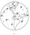
- FIG. 1is a simplified diagram of a communication system utilizing satellites that include a buffered packet switching network component, according to the present invention
- FIG. 2is a simplified diagram of a communication system that combines a satellite network with a terrestrial network, both of which include buffered packet switching network components, according to an embodiment of the present invention
- FIG. 3is a block diagram of a wireless backbone utilizing a router that includes a buffered packet switching network component, according to the present invention
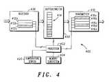
- FIG. 4is a block diagram of a buffered packet switching network component, which implements the present invention.
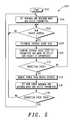
- FIG. 5is a flowchart of a power management routine that is utilized in conjunction with a bandwidth control mechanism, according to an embodiment of the present invention.
- the present inventionis directed to a buffered packet switching network component that provides a communication path between a packet source and a packet destination. More specifically, the present invention is directed to a technique for conserving power in a buffered packet switching network component that responds to a bandwidth control mechanism by reducing communication traffic in response to buffer congestion.
- a transition evente.g., low battery, high transmitter temperature, the expiration of a timer that indicates when an eclipse event will occur or an expensive power period
- a parameter of the bandwidth control mechanismis modified such that a transferred packet indicates the packet switching network component is congested.
- a packet sourceis requested to reduce its packet rate.
- Unused devices, such as transceivers, of the buffered packet switching network componentare then deactivated such that power is conserved.
- the present inventionis applicable to both space-based devices (e.g., satellites) and terrestrial-based devices (e.g., routers and gateways) that include buffered packet switching network components.
- the term “satellite”includes a man-made object or vehicle for orbiting a celestial body such as the Earth and encompasses both geostationary and orbiting satellites.
- the term “constellation”includes a group of satellites arranged in orbits for providing coverage (e.g., radio communication) over a portion or all of a celestial body and may include geostationary satellites, orbiting satellites (i.e., low-Earth orbiting (LEO) satellites and medium Earth orbiting satellites), or combinations of such satellites.
- a constellationtypically includes multiple rings (or planes) of satellites and may have equal numbers of satellites in each plane.
- the term “cell” and “antenna pattern”are not intended to be limited to any particular mode of generation and includes those created by either terrestrial or satellite cellular communication systems and/or combinations thereof.
- FIG. 1illustrates a simplified diagram of a communication system 10 that includes a plurality of orbiting satellites 12 occupying a plurality of polar orbits 14 .
- the present inventionis also applicable to satellite communication systems that have non-polar orbits (e.g., equatorial). While only nine satellites 12 and six polar orbits 14 are shown in FIG. 1, one of ordinary skill in the art will appreciate that any number of satellites or orbits may be utilized to provide a desired coverage.
- satellites 12are LEO satellites
- a line-of-sight electromagnetic (e.g., radio and light) communication of any one satellite 12covers a relatively small area of the Earth, at any instant.
- a typical LEO satellite 12travels at approximately twenty-five thousand kms/hr with respect to the Earth.
- each satellite 12is visible to a terrestrial station, such as individual subscriber unit (ISU) 26 , for a period of approximately nine minutes, according to the system shown.
- ISUsubscriber unit
- Each satellite 12communicates with terrestrial stations, which may include some number of ISUs 26 and Earth terminals (ETs) 24 connected to a system control segment (SCS) 28 or a gateway (GW) 22 .
- Each GW 22may provide access to a public switched telephone network (PSTN) (not shown in FIG. 1) or other communication facility.
- PSTNpublic switched telephone network
- ETs 24may be adjacent to or separate from SCSs 28 and/or GWs 22 .
- ETs 24 that are associated with SCSs 28receive data describing tracking of satellites 12 and relay packets of control information.
- ETs 24 associated with GW 22typically only relay data packets (e.g., relating to calls in progress).
- ISUs 26may be located anywhere on the surface of the Earth or in the atmosphere above the Earth, such as aboard an airplane. ISUs 26 are preferably communication devices capable of transmitting data to and receiving data from satellites 12 . By way of example, ISU 26 may be a hand-held portable cellular telephone adapted to communicate with satellites 12 . Normally, ISU 26 does not perform any control functions for communication system 10 .
- Communication system 10may accommodate a large number of ISUs 26 , which typically communicate with nearby satellites 12 via subscriber links 16 .
- Links 16encompass a limited portion of the electromagnetic spectrum that is divided into numerous channels.
- links 16may be combinations of L-Band frequency channels and may encompass various air interface standards (e.g., Frequency Division Multiple Access (FDMA), Time Division Multiple Access (TDMA), Code Division Multiple Access (CDMA)), or a combination of such air interface standards.
- FDMAFrequency Division Multiple Access
- TDMATime Division Multiple Access
- CDMACode Division Multiple Access
- satellite 12regularly transmits over one or more broadcast channels 18 .
- ISUs 26synchronize to broadcast channels 18 and monitor broadcast channels 18 to detect messages which are addressed to them.
- ISUs 26transmit messages to satellites 12 over one or more acquisition channels 19 .
- Broadcast channels 18 and acquisition channels 19are typically not dedicated to any one ISU 26 , but are shared by all ISUs 26 currently within the footprint of a given satellite 12 .
- Traffic channels 17are typically two-way real-time channels that are assigned to a particular ISU 26 , by a given satellite 12 , from time-to-time.
- a digital formatis used to communicate data over channels 17 - 19 .
- At least one traffic channel 17is assigned for each call, and each traffic channel 17 has sufficient bandwidth to support, at a minimum, a two-way voice conversation.
- a TDMA schememay be used to divide time into frames (e.g., ten to ninety milliseconds).
- each ISU 26is assigned a specific traffic channel 17 and specific transmit and receive time-slots within each frame of the specific traffic channel 17 .
- Analog audio signalsare preferably digitized such that during each frame the digitized audio signal is transmitted or received in a single short high-speed burst during an allotted time-slot.
- Each satellite 12may support up to a thousand or more traffic channels 17 such that each satellite 12 can simultaneously service a number of independent calls.
- traffic channels 17can be formed without a time-slot structure and that methods that do not require digitizing an analog signal (e.g., voice) may be employed.
- Various known techniquesmay be employed to form the channels and process the voice communication.
- Satellites 12communicate with other nearby satellites 12 through cross-links 23 .
- a call or communication from an ISU 26 located at any point on or near the surface of the Earthmay be routed through the constellation of satellites 12 to within range of substantially any other point on the surface of the Earth.
- a communicationmay be routed down to an ISU 26 on or near the surface of the Earth from a satellite 12 using subscriber link 16 .
- a communicationmay be routed down to or up from ETs 24 , of which FIG. 1 shows only two, through Earth links 15 .
- ETs 24are usually distributed over the surface of the Earth in accordance with geographical/political boundaries.
- Each satellite 12is preferably capable of communicating with multiple ETs 24 and ISUs 26 at any given instant.
- SCS 28monitors the health and status of system communication nodes (e.g., GWs 22 , ETs 24 and satellites 12 ) and normally manages operations of communication system 10 .
- One or more ETs 24provide the primary communications interface between SCS 28 and satellites 12 .
- ETs 24typically include antennas and RF transceivers for performing telemetry, tracking and control functions for the constellation of satellites 12 .
- GWs 22may perform call processing functions in conjunction with satellites 12 or GWs 22 may exclusively handle call processing and allocation of call handling capacity within communication system 10 .
- Various terrestrial-based communication systemssuch as the PSTN (not shown in FIG. 1 ), may access communication system 10 through GWs 22 .
- any satellite 12may be in direct or indirect data communication with any ISU 26 or ET 24 at any time by routing data through the constellation of satellites 12 .
- communication system 10may establish a communication path for relaying data through the constellation of satellites 12 between any two ISUs 26 , between SCS 28 and GW 22 , between any two GWs 22 or between ISU 26 and GW 22 .
- the present inventionis also applicable to satellite constellations where full coverage of the Earth is not achieved (i.e., where there are “holes” in the communications coverage provided by the constellation) and constellations where plural coverage of portions of the Earth occur (i.e., more than one satellite is in view of a point on the Earth's surface).
- communication system 10may be viewed as a network of nodes.
- Each satellite 12 , GW 22 , SCS 28 and ISU 26represents a node of communication system 10 .
- All nodes of communication system 10are or may be in data communication with any other node of communication system 10 , through communication links 15 , 16 and/or 23 .
- all nodes of communication system 10are or may be in data communication with other telephonic devices dispersed throughout the world through PSTNs and/or conventional terrestrial cellular telephone devices coupled to a PSTN through conventional terrestrial base stations.
- satellite 12continuously transmits over one or more broadcast channels 18 .
- ISUs 26synchronize to broadcast channels 18 and monitor the broadcast channels 18 .
- each ISU 26continually monitors the broadcast channel 18 of the cell in which it is located.
- Broadcast channels 18are not dedicated to any one ISU 26 , but are shared by all ISUs 26 currently within the footprint of a given satellite 12 .
- broadcast channel 18 antenna patternstravel across the surface of the Earth, while ISUs 26 remain relatively stationary.
- the antenna patterns dedicated to broadcast channel 18are relatively stationary, while ISUs 26 travel across the surface of the Earth.
- Assignments of traffic channels 17are valid while an ISU 26 remains within a given cell. Generally, based on the movement of a given satellite 12 , this period is approximately 30 seconds, according to one example. New traffic channel assignments must be established every period. Because of the fast moving antenna patterns, it is desirable for ISUs 26 to monitor the broadcast channels 18 of adjacent cells that are candidates for handoff. Typically, each ISU 26 is capable of operating with any of the discrete channel sets, and the particular channel set used at any particular time by any particular ISU 26 is controlled by communication system 10 .
- ISU 26typically determines which cell to communicate with based on the signal level of the broadcast channel 18 received at the ISU 26 . For example, an ISU 26 located within a center region of a cell will probably choose to communicate with the satellite 12 associated with the cell, because the broadcast channel 18 signal level of an antenna pattern is generally the greatest in the center region. If an ISU 26 is located within a region where two antenna patterns or cells overlap, ISU 26 may choose either cell to communicate with because the broadcast channel 18 signal levels are generally similar.
- a handoff candidate listis typically generated in advance by a GW 22 .
- GW 22by knowing the current geometric relationship between cells and the cell shut-down plan, predicts which candidate cells a given ISU 26 can utilize.
- GW 22transfers the time-sequenced handoff candidate list for each cell served by a satellite 12 to each of the satellites 12 , which in turn transmits the appropriate list to the ISUs 26 in each of its cells.
- the ISUs 26update their candidate list by observing differences between the broadcast channels 18 identified in the handoff candidate update messages and the broadcast channels 18 transmitted in previously provided candidate lists. Whether or not a channel in the current list remains valid is indicated by the current satellite 12 in the candidate update messages.
- a handoff requesttypically includes the candidate cell (e.g., the cell that the ISU 26 wants to transfer its communication).
- the satellite 12receives the handoff request from the ISU 26 , the satellite 12 first determines if it also services the requested candidate cell. In inter-cell handoff, the requested candidate cell is serviced by the satellite 12 .
- the satellite 12places the new uplink and downlink traffic channel assignment into a control field of the next downlink burst to the requesting ISU 26 .
- the ISU 26receives the new assignment, it waits until it has received all of the downlink burst and has sent the corresponding uplink burst.
- the ISU 26then tunes to the new traffic channel.
- the satellite 12directs the traffic for the requesting ISU 26 to the new channel.
- the Doppler and timing offsetsare the same for both cells at the time of the handoff and the ISU 26 can synchronize immediately. Following the handoff, the ISU 26 discards its current handoff candidate list and the satellite 12 provides a handoff candidate list for the new cell.
- a GW 22is typically responsible for routing the calls from a dialing ISU 26 to a receiving ISU 26 .
- Those skilled in the artwill readily recognize that there is no requirement that the handoff control functions be performed in a GW 22 . These functions can, for example, be performed in SCS 28 or in any one or a combination of satellites 12 (of FIG. 1 ).
- FIG. 2shows an ISU 26 that is capable of communicating with a satellite 12 of communication system 10 (i.e., a satellite network) and a terrestrial network.
- the satellite network and the terrestrial networkare radio frequency (RF) networks which are, for example, cellular communication networks.
- ISU 26can be, for example, an RF telephone, radio or pager adapted to communicate over networks having different air interface standards.
- the satellite networkincludes satellite GW 22 , satellite ET 24 and satellite 12 .
- GW 22is a switching facility which interfaces the satellite network 10 with other communication networks (e.g., public switched telephone network (PSTN) 30 or a cellular radio telecommunication network 39 ).
- PSTNpublic switched telephone network
- GW 22thus, enables ISU 26 to communicate with a conventional telephone 32 and with other communication devices (e.g., RF telephones and pagers).
- other communication devicese.g., RF telephones and pagers.
- ET 24which is controlled by GW 22 , provides an RF interface between GW 22 and satellite 12 .
- Satellite 12provides at least one communication channel to ISU 26 .
- communication channelsare provided by projecting beams toward ISU 26 which results in coverage footprint 34 on the surface of the Earth.
- the terrestrial radio telecommunication network 39includes a terrestrial GW 36 and an RF antenna 38 .
- GW 36is functionally the same as or equivalent to GW 22 . That is, GW 36 includes a buffer/switch and other circuitry which interfaces the terrestrial network with other communication networks and enables ISU 26 to communicate with a conventional telephone 32 and with other communication devices.
- GW 36controls RF antenna 38 , which provides at least one communication channel by projecting beams toward ISU 26 that result in coverage footprint 40 on the surface of the Earth.
- ISU 26(of FIG. 2) must typically be capable of handing-off between networks having differing air interface standards and differing locational standards.
- Connection 42couples satellite GW 22 to terrestrial GW 36 and allows GW 22 and GW 36 to exchange messages and data.
- GWs 22 and 36may communicate through a packet network (e.g., system signaling No. 7 (SS7)), which routes messages between GWs 22 and 36 .
- SS7system signaling No. 7
- An ISU 26might desire an inter-network handoff, for example, when an ISU 26 power measurement of the communication channel indicates that the channel is fading.
- ISU 26may request an inter-network handoff.
- ISU 26may specify an alternate network to which the ISU 26 prefers to be handed off.
- ISU 26can also send the alternate cell identification number in the inter-network handoff request.
- a GW 22 or 36may desire an inter-network handoff, for example, when GW 22 or 36 wants to shed some of the traffic load which GW 22 or 36 is supporting. This may occur, for example, if a scheduled or unscheduled service outage is occurring or will occur in the near future. Another reason GW 22 or 36 might want to shed some of its load when it is experiencing higher than desired traffic volume. As another example, if GW 22 or 36 wants to maintain a certain number of channels for high-priority users it might drop some lower-priority users.
- FIG. 3illustrates an exemplary wireless local area network (WLAN) 300 , preferably implemented as a computer network, that includes a router 310 that couples a wireless device (e.g., ISU 26 ) to a wired network 302 .
- a wireless devicee.g., ISU 26
- router 310connects ISUs 26 A or 26 B to wired network 302 , filters packets based on a destination address and passes packets to/from WLAN 300 , as required.
- access points (APs) 304 A and 304 Be.g., Lucent WavePoint IITM units
- Hub 306 Ais coupled to wired network 302 by switches 308 A and 308 B and router 310 .
- APs 304 C and 304 Dare coupled to hub 306 B.
- Hub 306 Bis coupled to wired network 302 by switch 308 A and router 310 . It is contemplated that the present invention can be beneficially incorporated within router 310 of WLAN 300 .
- ISU 26can be, for example, a laptop computer or a handheld computer (e.g., a personal digital assistant (PDA)) that is capable of communicating with wired network 302 , as ISUs 26 A and 26 B move from location to location.
- APs 304 A, 304 B, 304 C and 304 Dare radio base stations that are mounted at fixed locations so as to provide access to wired network 302 or allow communication between multiple ISUs 26 .
- APs 304typically include a transmitter, receiver, antenna, and a bridge that routes packets, for example, to/from wired network 302 , as appropriate.
- ISU 26is a mobile computer that includes a network adapter (NA) that enables wireless communication.
- NAnetwork adapter
- a typical NAincludes a transmitter, a receiver, an antenna and hardware that provides a data interface to ISU 26 .
- WLAN 300allows roaming. That is, ISUs 26 can accept handoffs as they change coverage areas such that service is continuous. Similar to other systems (e.g., satellite-based systems), in order for a handoff to be successful, it is necessary that tables (located in, for example, a bridge of each AP 304 ) are updated as the ISUs 26 move from one AP 304 coverage area to another.
- direct peer-to-peer (i.e., ISU 26 A to ISU 26 B) communicationcan be provided in one of two ways. Either an ISU 26 can communicate directly with another ISU 26 or two ISUs 26 can communicate by having transmissions relayed by one or more APs 304 .
- ISU 26 Bcan communicate with ISU 26 A through AP 304 A or through AP 304 A, hub 306 A and AP 304 B.
- a buffered network packet switched component 400is shown that can be incorporated within, for example, satellite 12 (FIGS. 1 and 2 ), gateways 22 and 36 (FIG. 2) and/or router 310 (FIG. 3 ).
- a processor 402is coupled to a memory subsystem 404 , a receiver 406 , a buffer/switch 408 and a transmitter 410 .
- Receiver 406is a multichannel receiver that includes a number of channels 412 A, 412 B and 412 C. While only three input channels are shown, one of ordinary skill in the art will appreciate that any number of channels can be implemented, as required.
- Transmitter 410is a multichannel transmitter that includes a number of output channels 416 A, 416 B, 416 C, 416 D and 416 E. While only five output channels are shown, one of ordinary skill in the art will appreciate that any number of output channels can be implemented, as desired. Although transmitter 410 and receiver 406 are shown as separate units, one of ordinary skill in the art will appreciate the transmitter 410 and receiver 406 can readily be implemented within a single unit.
- Processor 402controls channels 412 A, 412 B and 412 C and determines whether a packet received on one of the channels is temporarily stored in FIFO buffer 414 or discarded. Processor 402 also monitors the state of buffer 414 and executes a bandwidth control mechanism (e.g., RED). Processor 402 takes an appropriate action to cause a packet to be marked or discarded as dictated by the bandwidth control mechanism. As shown in FIG. 4, input channel 412 C is currently active, FIFO buffer 414 is currently half-full and output channels 416 A and 416 D are currently active. Buffer/switch 408 routes traffic to an active channel as dictated by processor 402 .
- a bandwidth control mechanisme.g., RED
- the intent of REDis to prevent buffer 414 overflow while maintaining a near maximum utilization of the packet network.
- a given RED algorithmperforms a time-weighted average buffer size calculation that is compared to a set of marking and/or deleting parameters. If the average buffer size falls below the minimum parameter, no action is taken. If the average buffer size falls above the maximum parameter, the action of marking or deleting occurs. When the average buffer size falls between the minimum and maximum parameters, the probability that the action will occur is a function (typically a linear function) of the average buffer size.
- Power managementwhen implemented, takes control of the bandwidth control mechanism by lowering the minimum and maximum parameters (i.e., the marking and/or deleting parameters). As the parameters are decreased, certain packets are marked or deleted. A cooperating packet destination will receive a marked packet and determine that packet congestion exists along the packet route. The packet destination will then inform the packet source (through, for example, a dedicated message or by setting a bit in a response packet) that a particular buffer/switch along the current packet route is congested.
- the minimum and maximum parametersi.e., the marking and/or deleting parameters.
- the marking and/or deleting parametersAs the parameters are decreased, certain packets are marked or deleted.
- a cooperating packet destinationwill receive a marked packet and determine that packet congestion exists along the packet route. The packet destination will then inform the packet source (through, for example, a dedicated message or by setting a bit in a response packet) that a particular buffer/switch along the current packet route is congested.
- a transition eventcan be provided by a sensor that monitors a battery voltage, a sensor that monitors an ambient light level or can be based on a timer.
- a transition eventcan be precipitated by temperature sensor 420 indicating that the temperature of transmitter 416 is above a desired level or by a time of day when, for example, power is more expensive for a terrestrial-based buffer/switch.
- routine 500is shown that is utilized in conjunction with a bandwidth control mechanism (e.g., RED), according to an embodiment of the present invention.
- Routine 500is initiated in step 502 .
- routine 500causes a minimum and a maximum mark and/or delete parameter to be set to a desired value.
- decision step 506routine 500 determines whether a new packet has arrived. When a new packet arrives, control transfers from step 506 to step 508 .
- routine 500determines the average queue size.
- routine 500compares the average queue size to the minimum and maximum mark and/or delete parameters and marks or deletes a new packet, if appropriate. From step 510 , control transfers to decision step 512 .
- routine 500detects whether the buffered packet switching network component has had a transition event.
- a transition eventmay be initiated by a low battery condition.
- a low battery conditionis typically a result of an eclipse event that prevents a solar panel of a satellite from providing an adequate amount of charge to the battery such that the current communication traffic load can be maintained.
- a transition eventcan also be initiated by a timer that indicates when an eclipse event will occur. Further, the transition event may be initiated by an over-temperature event. Such an event is applicable to both space-based and terrestrial-based communication systems that include a buffered packet switching network component.
- step 514routine 500 causes power to be removed from unused devices (e.g., transmitters and receivers).
- step 516new lower minimum and maximum mark and/or delete parameters are set.
- decision step 518routine 500 determines whether the transition event is on-going. If so, control transfers from step 518 to step 506 . Otherwise, control transfers from step 518 back to step 504 .
- power managementforces an implemented bandwidth control mechanism (e.g., RED) to artificially increase the probability of network congestion notification.
- REDbandwidth control mechanism
- Thisallows network users to detect congestion and negotiate a lower packet rate, which reduces network throughput allowing unused network resources (e.g., transmitters) to be shut-down to conserve power.
- unused network resourcese.g., transmitters
- the present inventiondoes not require complex network/link layer messaging to notify users of impending network traffic reduction.
- the present inventionmakes RED an active network traffic regulator rather than a reactive network traffic regulator.
- the present inventionin combination with RED, can control utilization of any network component whose power consumption is a function of traffic.
- the present inventioncan be implemented in software with existing bandwidth control algorithms, such as RED.
- the present inventioncan be implemented in hardware within an application specific integrated circuit (ASIC).
- ASICapplication specific integrated circuit
- the present inventionis particularly advantageous when implemented within a satellite as it reduces the complexity of the required power management, which translates into a reduction of size, weight and power, which, in turn, reduces the payload of the satellite.
- the present inventionis applicable to any buffer/switch that provides a power management port that allows traffic to be reduced for reasons other than buffer congestion.
Landscapes
- Engineering & Computer Science (AREA)
- Computer Networks & Wireless Communication (AREA)
- Signal Processing (AREA)
- Radio Relay Systems (AREA)
- Mobile Radio Communication Systems (AREA)
Abstract
Description
1. Field of the Invention
The present invention is generally directed to a communication system, and more particularly to managing the power utilized by a buffered packet switching network component of a communication system.
2. Background Information
Various bandwidth control mechanisms have been utilized for congestion avoidance in communications systems that include buffered packet switching network components. For example, a number of random early detection (RED) algorithms have been implemented in terrestrial-based gateways. A typical gateway, implementing a RED algorithm, notifies packet sources and packet destinations of congestion either by dropping packets or by setting a bit in a header of a given packet. In this manner, a RED gateway attempts to keep its average queue size low while storing occasional bursts of packets in its queue.
Various forms of RED algorithms have been implemented within gateways. Examples of known RED algorithms include weighted RED, adaptive RED, distributed RED, distributed weighted RED, etc. Such algorithms implementing the assorted forms of RED are well known to one of ordinary skill in the art. RED algorithms have also been implemented in packet-based network components that include buffers (e.g., FIFO buffers) other than gateways (e.g., routers). As mentioned above, the purpose of RED is to prevent buffer overflow while maintaining a near maximum utilization of the packet network. A given RED algorithm generally performs a time-weighted average buffer size calculation that is compared to a set of marking and/or deleting parameters. If the average buffer size falls below the minimum parameters, no action is taken. If the average buffer size exceeds the maximum parameters, an action, such as marking or deleting, is guaranteed to occur. When the average buffer size falls between the minimum and maximum parameters, the probability that an action (marking or deleting) will occur is a function, e.g., linear proportion, of the average buffer size.
An adaptive RED implementation monitors how long the average buffer size is in each of three distinct domains (i.e., less than a minimum, between the minimum and a maximum, and greater than the maximum) and adjusts the minimum and maximum parameters for marking and deleting, accordingly. Reducing either marking parameter increases the probability that a packet is marked, thus signaling congestion to the packet destination. In response to receiving a marked packet, a packet destination typically sends a request to the packet source to reduce the rate at which packets are sent through the congested link. In this manner, the various forms of RED attempt to enlist the aid of network users to voluntarily reduce traffic, so as to prevent buffer overflow and the subsequent loss of packets. RED algorithms have also been implemented in various space-based packet switching network components (e.g., satellites) in an effort to reduce component congestion.
In addition to congestion in a packet switching network component, another matter of concern with respect to satellites and many other devices that include packet switching network components, is power management. A typical satellite includes storage cells or batteries that supply operating power to the electronic circuits of the satellite. These storage cells or batteries, which are recharged by solar panels, store energy for use during high power demands or during dark periods. Dark periods occur when a given satellite, within a constellation, is shadowed from the Sun by the Earth. At most, a typical satellite, within a constellation, may be shadowed by the Earth for thirty-five percent of its orbit. At best, each individual satellite is typically in full view of the sun for approximately thirty percent of its orbit. Thus, during high power demands or dark periods, satellite power management is typically necessary. Additionally, terrestrial-based packet switching network components can benefit from power management (i.e., conservation) during peak power usage, among other conditions.
The present invention will hereinafter be described in conjunction with the appended drawings figures, wherein like numerals denote like elements, and:
FIG. 1 is a simplified diagram of a communication system utilizing satellites that include a buffered packet switching network component, according to the present invention;
FIG. 2 is a simplified diagram of a communication system that combines a satellite network with a terrestrial network, both of which include buffered packet switching network components, according to an embodiment of the present invention;
FIG. 3 is a block diagram of a wireless backbone utilizing a router that includes a buffered packet switching network component, according to the present invention;
FIG. 4 is a block diagram of a buffered packet switching network component, which implements the present invention; and
FIG. 5 is a flowchart of a power management routine that is utilized in conjunction with a bandwidth control mechanism, according to an embodiment of the present invention.
The ensuing detailed description provides preferred exemplary embodiments only, and is not intended to limit the scope, applicability or configuration of the invention. Rather, the ensuing detailed description of the preferred exemplary embodiment(s) will provide those skilled in the art with an enabling description for implementing a preferred exemplary embodiment of the invention. It being understood that various changes may be made in the function and arrangement of elements without departing from the spirit and scope of the invention as set forth in the appended claims.
The present invention is directed to a buffered packet switching network component that provides a communication path between a packet source and a packet destination. More specifically, the present invention is directed to a technique for conserving power in a buffered packet switching network component that responds to a bandwidth control mechanism by reducing communication traffic in response to buffer congestion. When the buffered packet switching network component has a transition event (e.g., low battery, high transmitter temperature, the expiration of a timer that indicates when an eclipse event will occur or an expensive power period), a parameter of the bandwidth control mechanism is modified such that a transferred packet indicates the packet switching network component is congested. In response to the congestion of the network component, a packet source is requested to reduce its packet rate. Unused devices, such as transceivers, of the buffered packet switching network component are then deactivated such that power is conserved. The present invention is applicable to both space-based devices (e.g., satellites) and terrestrial-based devices (e.g., routers and gateways) that include buffered packet switching network components.
As utilized herein, the term “satellite” includes a man-made object or vehicle for orbiting a celestial body such as the Earth and encompasses both geostationary and orbiting satellites. As used herein, the term “constellation” includes a group of satellites arranged in orbits for providing coverage (e.g., radio communication) over a portion or all of a celestial body and may include geostationary satellites, orbiting satellites (i.e., low-Earth orbiting (LEO) satellites and medium Earth orbiting satellites), or combinations of such satellites. A constellation typically includes multiple rings (or planes) of satellites and may have equal numbers of satellites in each plane. The term “cell” and “antenna pattern” are not intended to be limited to any particular mode of generation and includes those created by either terrestrial or satellite cellular communication systems and/or combinations thereof.
FIG. 1 illustrates a simplified diagram of acommunication system 10 that includes a plurality of orbitingsatellites 12 occupying a plurality ofpolar orbits 14. The present invention is also applicable to satellite communication systems that have non-polar orbits (e.g., equatorial). While only ninesatellites 12 and sixpolar orbits 14 are shown in FIG. 1, one of ordinary skill in the art will appreciate that any number of satellites or orbits may be utilized to provide a desired coverage.
Whensatellites 12 are LEO satellites, a line-of-sight electromagnetic (e.g., radio and light) communication of any onesatellite 12 covers a relatively small area of the Earth, at any instant. A typical LEOsatellite 12 travels at approximately twenty-five thousand kms/hr with respect to the Earth. As such, eachsatellite 12 is visible to a terrestrial station, such as individual subscriber unit (ISU)26, for a period of approximately nine minutes, according to the system shown.
Eachsatellite 12 communicates with terrestrial stations, which may include some number ofISUs 26 and Earth terminals (ETs)24 connected to a system control segment (SCS)28 or a gateway (GW)22. EachGW 22 may provide access to a public switched telephone network (PSTN) (not shown in FIG. 1) or other communication facility.ETs 24 may be adjacent to or separate fromSCSs 28 and/orGWs 22.ETs 24 that are associated withSCSs 28 receive data describing tracking ofsatellites 12 and relay packets of control information.ETs 24 associated withGW 22 typically only relay data packets (e.g., relating to calls in progress).
ISUs26 may be located anywhere on the surface of the Earth or in the atmosphere above the Earth, such as aboard an airplane.ISUs 26 are preferably communication devices capable of transmitting data to and receiving data fromsatellites 12. By way of example,ISU 26 may be a hand-held portable cellular telephone adapted to communicate withsatellites 12. Normally,ISU 26 does not perform any control functions forcommunication system 10.
When the Earth is fully covered bysatellites 12, anysatellite 12 may be in direct or indirect data communication with anyISU 26 orET 24 at any time by routing data through the constellation ofsatellites 12. Accordingly,communication system 10 may establish a communication path for relaying data through the constellation ofsatellites 12 between any twoISUs 26, betweenSCS 28 andGW 22, between any twoGWs 22 or betweenISU 26 andGW 22. The present invention is also applicable to satellite constellations where full coverage of the Earth is not achieved (i.e., where there are “holes” in the communications coverage provided by the constellation) and constellations where plural coverage of portions of the Earth occur (i.e., more than one satellite is in view of a point on the Earth's surface).
In general terms,communication system 10 may be viewed as a network of nodes. Eachsatellite 12,GW 22,SCS 28 andISU 26 represents a node ofcommunication system 10. All nodes ofcommunication system 10 are or may be in data communication with any other node ofcommunication system 10, throughcommunication links communication system 10 are or may be in data communication with other telephonic devices dispersed throughout the world through PSTNs and/or conventional terrestrial cellular telephone devices coupled to a PSTN through conventional terrestrial base stations.
As discussed previously,satellite 12 continuously transmits over one ormore broadcast channels 18.ISUs 26 synchronize to broadcastchannels 18 and monitor thebroadcast channels 18. Preferably, eachISU 26 continually monitors thebroadcast channel 18 of the cell in which it is located.Broadcast channels 18 are not dedicated to any oneISU 26, but are shared by allISUs 26 currently within the footprint of a givensatellite 12. In systems that utilize satellites.12 in non-geosynchronous orbits,broadcast channel 18 antenna patterns travel across the surface of the Earth, while ISUs26 remain relatively stationary. In systems that utilizesatellites 12 in geosynchronous orbits, the antenna patterns dedicated to broadcastchannel 18 are relatively stationary, whileISUs 26 travel across the surface of the Earth.
Assignments oftraffic channels 17 are valid while anISU 26 remains within a given cell. Generally, based on the movement of a givensatellite 12, this period is approximately 30 seconds, according to one example. New traffic channel assignments must be established every period. Because of the fast moving antenna patterns, it is desirable forISUs 26 to monitor thebroadcast channels 18 of adjacent cells that are candidates for handoff. Typically, eachISU 26 is capable of operating with any of the discrete channel sets, and the particular channel set used at any particular time by anyparticular ISU 26 is controlled bycommunication system 10.
A handoff candidate list is typically generated in advance by aGW 22.GW 22, by knowing the current geometric relationship between cells and the cell shut-down plan, predicts which candidate cells a givenISU 26 can utilize.GW 22 transfers the time-sequenced handoff candidate list for each cell served by asatellite 12 to each of thesatellites 12, which in turn transmits the appropriate list to theISUs 26 in each of its cells. The ISUs26 update their candidate list by observing differences between thebroadcast channels 18 identified in the handoff candidate update messages and thebroadcast channels 18 transmitted in previously provided candidate lists. Whether or not a channel in the current list remains valid is indicated by thecurrent satellite 12 in the candidate update messages.
A handoff request typically includes the candidate cell (e.g., the cell that theISU 26 wants to transfer its communication). When thesatellite 12 receives the handoff request from theISU 26, thesatellite 12 first determines if it also services the requested candidate cell. In inter-cell handoff, the requested candidate cell is serviced by thesatellite 12. Thesatellite 12 places the new uplink and downlink traffic channel assignment into a control field of the next downlink burst to the requestingISU 26. When theISU 26 receives the new assignment, it waits until it has received all of the downlink burst and has sent the corresponding uplink burst. TheISU 26 then tunes to the new traffic channel. Next, thesatellite 12 directs the traffic for the requestingISU 26 to the new channel. Since both the old and new channels are on thesame satellite 12, the Doppler and timing offsets are the same for both cells at the time of the handoff and theISU 26 can synchronize immediately. Following the handoff, theISU 26 discards its current handoff candidate list and thesatellite 12 provides a handoff candidate list for the new cell.
AGW 22 is typically responsible for routing the calls from a dialingISU 26 to a receivingISU 26. Those skilled in the art will readily recognize that there is no requirement that the handoff control functions be performed in aGW 22. These functions can, for example, be performed inSCS 28 or in any one or a combination of satellites12 (of FIG.1).
FIG. 2 shows anISU 26 that is capable of communicating with asatellite 12 of communication system10 (i.e., a satellite network) and a terrestrial network. Preferably, the satellite network and the terrestrial network are radio frequency (RF) networks which are, for example, cellular communication networks.ISU 26 can be, for example, an RF telephone, radio or pager adapted to communicate over networks having different air interface standards. As shown in FIG. 2, the satellite network includessatellite GW 22,satellite ET 24 andsatellite 12. As described above,GW 22 is a switching facility which interfaces thesatellite network 10 with other communication networks (e.g., public switched telephone network (PSTN)30 or a cellular radio telecommunication network39).
The terrestrialradio telecommunication network 39 includes aterrestrial GW 36 and anRF antenna 38.GW 36 is functionally the same as or equivalent toGW 22. That is,GW 36 includes a buffer/switch and other circuitry which interfaces the terrestrial network with other communication networks and enablesISU 26 to communicate with aconventional telephone 32 and with other communication devices.GW 36controls RF antenna 38, which provides at least one communication channel by projecting beams towardISU 26 that result incoverage footprint 40 on the surface of the Earth.
One of ordinary skill in the art will appreciate that ISU26 (of FIG. 2) must typically be capable of handing-off between networks having differing air interface standards and differing locational standards.Connection 42couples satellite GW 22 toterrestrial GW 36 and allowsGW 22 andGW 36 to exchange messages and data. GWs22 and36 may communicate through a packet network (e.g., system signaling No. 7 (SS7)), which routes messages betweenGWs
AnISU 26 might desire an inter-network handoff, for example, when anISU 26 power measurement of the communication channel indicates that the channel is fading. As another example, whenISU 26 is capable of determining that it is located in an area where one or more alternate networks can provide higher quality service or service at a lower rate,ISU 26 may request an inter-network handoff. As part of the inter-network handoff request,ISU 26 may specify an alternate network to which theISU 26 prefers to be handed off. WhenISU 26 is capable of determining which cell of thealternate network ISU 26 is located within,ISU 26 can also send the alternate cell identification number in the inter-network handoff request.
AGW GW GW reason GW GW
FIG. 3 illustrates an exemplary wireless local area network (WLAN)300, preferably implemented as a computer network, that includes arouter 310 that couples a wireless device (e.g., ISU26) to awired network 302. As implemented inWLAN 300,router 310 connects ISUs26A or26B towired network 302, filters packets based on a destination address and passes packets to/fromWLAN 300, as required. As shown, access points (APs)304A and304B (e.g., Lucent WavePoint II™ units) are coupled to hub306A. Hub306A is coupled towired network 302 by switches308A and308B androuter 310. APs304C and304D are coupled to hub306B. Hub306B is coupled towired network 302 by switch308A androuter 310. It is contemplated that the present invention can be beneficially incorporated withinrouter 310 ofWLAN 300.
In the embodiment shown in FIG. 3,ISU 26 can be, for example, a laptop computer or a handheld computer (e.g., a personal digital assistant (PDA)) that is capable of communicating withwired network 302, as ISUs26A and26B move from location to location. APs304A,304B,304C and304D are radio base stations that are mounted at fixed locations so as to provide access towired network 302 or allow communication betweenmultiple ISUs 26. APs304 typically include a transmitter, receiver, antenna, and a bridge that routes packets, for example, to/fromwired network 302, as appropriate.
As shown,ISU 26 is a mobile computer that includes a network adapter (NA) that enables wireless communication. A typical NA includes a transmitter, a receiver, an antenna and hardware that provides a data interface toISU 26. As is typical of wireless systems,WLAN 300 allows roaming. That is,ISUs 26 can accept handoffs as they change coverage areas such that service is continuous. Similar to other systems (e.g., satellite-based systems), in order for a handoff to be successful, it is necessary that tables (located in, for example, a bridge of each AP304) are updated as theISUs 26 move from one AP304 coverage area to another. In a typical WLAN, direct peer-to-peer (i.e., ISU26A to ISU26B) communication can be provided in one of two ways. Either anISU 26 can communicate directly with anotherISU 26 or twoISUs 26 can communicate by having transmissions relayed by one or more APs304. For example, ISU26B can communicate with ISU26A through AP304A or through AP304A, hub306A and AP304B.
Referring to FIG. 4, a buffered network packet switchedcomponent 400 is shown that can be incorporated within, for example, satellite12 (FIGS.1 and2),gateways 22 and36 (FIG. 2) and/or router310 (FIG.3). Aprocessor 402 is coupled to amemory subsystem 404, areceiver 406, a buffer/switch 408 and atransmitter 410.Receiver 406 is a multichannel receiver that includes a number of channels412A,412B and412C. While only three input channels are shown, one of ordinary skill in the art will appreciate that any number of channels can be implemented, as required.Transmitter 410 is a multichannel transmitter that includes a number of output channels416A,416B,416C,416D and416E. While only five output channels are shown, one of ordinary skill in the art will appreciate that any number of output channels can be implemented, as desired. Althoughtransmitter 410 andreceiver 406 are shown as separate units, one of ordinary skill in the art will appreciate thetransmitter 410 andreceiver 406 can readily be implemented within a single unit.
As mentioned above, the intent of RED is to preventbuffer 414 overflow while maintaining a near maximum utilization of the packet network. A given RED algorithm performs a time-weighted average buffer size calculation that is compared to a set of marking and/or deleting parameters. If the average buffer size falls below the minimum parameter, no action is taken. If the average buffer size falls above the maximum parameter, the action of marking or deleting occurs. When the average buffer size falls between the minimum and maximum parameters, the probability that the action will occur is a function (typically a linear function) of the average buffer size.
Power management, when implemented, takes control of the bandwidth control mechanism by lowering the minimum and maximum parameters (i.e., the marking and/or deleting parameters). As the parameters are decreased, certain packets are marked or deleted. A cooperating packet destination will receive a marked packet and determine that packet congestion exists along the packet route. The packet destination will then inform the packet source (through, for example, a dedicated message or by setting a bit in a response packet) that a particular buffer/switch along the current packet route is congested.
In response to the message from the packet destination, a cooperating packet source will lower its packet send rate and/or perhaps seek an alternate route. A transition event can be provided by a sensor that monitors a battery voltage, a sensor that monitors an ambient light level or can be based on a timer. In addition, a transition event can be precipitated bytemperature sensor 420 indicating that the temperature oftransmitter 416 is above a desired level or by a time of day when, for example, power is more expensive for a terrestrial-based buffer/switch.
Referring to FIG. 5, apower management routine 500 is shown that is utilized in conjunction with a bandwidth control mechanism (e.g., RED), according to an embodiment of the present invention.Routine 500 is initiated instep 502. Next, instep 504, routine500 causes a minimum and a maximum mark and/or delete parameter to be set to a desired value. Then, indecision step 506, routine500 determines whether a new packet has arrived. When a new packet arrives, control transfers fromstep 506 to step508. Instep 508, routine500 determines the average queue size. Next, instep 510, routine500 compares the average queue size to the minimum and maximum mark and/or delete parameters and marks or deletes a new packet, if appropriate. Fromstep 510, control transfers todecision step 512.
Instep 512, routine500 detects whether the buffered packet switching network component has had a transition event. In a satellite, a transition event may be initiated by a low battery condition. A low battery condition is typically a result of an eclipse event that prevents a solar panel of a satellite from providing an adequate amount of charge to the battery such that the current communication traffic load can be maintained. One of ordinary skill in the art will appreciate that a transition event can also be initiated by a timer that indicates when an eclipse event will occur. Further, the transition event may be initiated by an over-temperature event. Such an event is applicable to both space-based and terrestrial-based communication systems that include a buffered packet switching network component. When a transition event has not occurred, control transfers fromstep 512 to step506.
When a transition event has occurred, control transfers fromstep 512 to step514. In step514, routine500 causes power to be removed from unused devices (e.g., transmitters and receivers). Next, instep 516, new lower minimum and maximum mark and/or delete parameters are set. Then, indecision step 518, routine500 determines whether the transition event is on-going. If so, control transfers fromstep 518 to step506. Otherwise, control transfers fromstep 518 back to step504.
Thus, a technique has been described which conserves power in a buffered packet switching network component, that responds to a bandwidth control mechanism, by reducing communication traffic in response to buffer congestion. Implementing the present invention with a bandwidth control mechanism, such as RED, minimizes the complexity of power management, while at the same time allowing customers to maintain a quality of service (QOS) as resources are taken off-line by placing the responsibility for throughput reduction on network users. This technique typically provides for a rapid response to power reduction requirements without normally having to drop packets, which negatively impacts the QOS.
As previously stated, power management forces an implemented bandwidth control mechanism (e.g., RED) to artificially increase the probability of network congestion notification. This allows network users to detect congestion and negotiate a lower packet rate, which reduces network throughput allowing unused network resources (e.g., transmitters) to be shut-down to conserve power. This is advantageous in that most prior art techniques shut-down resources without warning, which results in packets being dropped and the QOS being lowered. Further, the present invention does not require complex network/link layer messaging to notify users of impending network traffic reduction. The present invention makes RED an active network traffic regulator rather than a reactive network traffic regulator.
The present invention, in combination with RED, can control utilization of any network component whose power consumption is a function of traffic. The present invention can be implemented in software with existing bandwidth control algorithms, such as RED. Alternatively, the present invention can be implemented in hardware within an application specific integrated circuit (ASIC). Adding power management to a simple RED software implementation can be achieved with a single conditional clause (logic OR expression) tied to the statement that executes the packet marking and/or deleting.
The present invention is particularly advantageous when implemented within a satellite as it reduces the complexity of the required power management, which translates into a reduction of size, weight and power, which, in turn, reduces the payload of the satellite. The present invention is applicable to any buffer/switch that provides a power management port that allows traffic to be reduced for reasons other than buffer congestion.
While the principles of the invention have been described above in connection with specific apparatus, it is to be clearly understood that this description is made only by way of example and not as a limitation on the scope of the invention.
Claims (18)
1. A method of conserving power in a buffered packet switching network component that responds to a bandwidth control mechanism by reducing communication traffic in response to buffer congestion, the buffered packet switching network component providing a communication path between a packet source and a packet destination, said method comprising the steps of:
detecting when a buffered packet switching network component has a transition event;
modifying a parameter of a bandwidth control mechanism in response to the transition event such that a transferred packet indicates the buffered packet switching network component is congested;
requesting a packet source to reduce a packet rate in response to the transition event;
deactivating unused devices of the buffered packet switching network component such that power is conserved; and
the transition event is a low battery condition a timer expiration, or a temperature change.
2. The method ofclaim 1 , wherein the bandwidth control mechanism is random early detection (RED).
3. The method ofclaim 1 , wherein the buffered packet switching network component is included within a satellite.
4. The method ofclaim 1 , wherein the buffered packet switching network component is included within a router.
5. The method ofclaim 1 , wherein the low battery condition is a result of an eclipse event that prevents a solar panel of a satellite from providing an adequate amount of power to maintain a current communication traffic load.
6. The method ofclaim 1 , wherein the parameter includes a marking parameter and a deleting parameter.
7. The method ofclaim 1 , wherein the transition event is expiration a timer that indicates when an eclipse event will occur.
8. The method ofclaim 1 , wherein the transition event is an over-temperature event.
9. A buffered packet switching network component that responds to a bandwidth control mechanism by reducing communication traffic in response to buffer congestion, the buffered packet switching network component providing a communication path between a packet source and a packet destination, said buffered packet switching network component comprising:
a multi-channel receiver for receiving packetized information from a packet source;
a memory for buffering the packetized information;
a multi-channel transmitter for transmitting the received packetized information to a packet destination;
a switch for providing the buffered packetized information to the multi-channel transmitter;
a processor coupled to and controlling the multi-channel receiver, the memory, the multi-channel transmitter and the switch; and
processor executable code, for causing the processor to perform the steps of:
detecting when a buffered packet switching network component has a transition event;
modifying a parameter of a bandwidth control mechanism in response to the transition event such that a transferred packet indicates the buffered packet switching network component is congested; a
deactivating unused devices of the buffered packet switching network component such that power is conserved, wherein the packet destination requests the packet source reduce its packet rate in response to the transition event; and
the transition event is a low battery conditions a timer expiration, or a temperture change.
10. The buffered packet switching network component ofclaim 9 , wherein the bandwidth control mechanism is random early detection (RED).
11. The buffered packet switching network component ofclaim 9 , wherein the buffered packet switching network component is included within a satellite.
12. The buffered packet switching network component ofclaim 9 , wherein the buffered packet switching network component is included within a router.
13. The buffered packet switching network component ofclaim 9 , wherein the low battery condition is a result of an eclipse event that prevents a solar panel of a satellite from providing an adequate amount of power to maintain a current communication traffic load.
14. The buffered packet switching network component ofclaim 9 , wherein the parameter includes a marking parameter and a deleting parameter.
15. The buffered packet switching network component ofclaim 9 , wherein the transition event is expiration a timer that indicates when an eclipse event will occur.
16. The buffered packet switching network component ofclaim 9 , wherein the transition event is an over-temperature event.
17. A satellite that includes a buffered packet switching network component that responds to a bandwidth control mechanism by reducing communication traffic in response to buffer congestion, the buffered packet switching network component providing a communication path between a packet source and a packet destination, said satellite comprising;
a multi-channel receiver for receiving packetized information from a packet source;
a memory for buffering the packetized information;
a multi-channel transmitter for transmitting the received packetized information to a packet destination;
a switch for providing the buffered packetized information to the multi-channel transmitter;
a processor coupled to and controlling the multi-channel receiver, the memory, the multi-channel transmitter and the switch; and
processor executable code, for causing the processor to perform the steps of:
detecting when a buffered packet switching network component has a transition event;
modifying a parameter of a bandwidth control mechanism in response to the transition event such that a transferred packet indicates the buffered packet switching network component is congested; and
deactivating unused devices of the buffered packet switching network component such that power is conserved, wherein the packet destination requests the packet source reduce its packet rate in response to the transition event; and
the transition event is a low battery condition a timer expiration, or temperature change.
18. The satellite ofclaim 17 , wherein the bandwidth control mechanism ie random early detection (RED).
Priority Applications (1)
| Application Number | Priority Date | Filing Date | Title |
|---|---|---|---|
| US09/594,617US6731613B1 (en) | 2000-06-14 | 2000-06-14 | Power management using a bandwidth control mechanism |
Applications Claiming Priority (1)
| Application Number | Priority Date | Filing Date | Title |
|---|---|---|---|
| US09/594,617US6731613B1 (en) | 2000-06-14 | 2000-06-14 | Power management using a bandwidth control mechanism |
Publications (1)
| Publication Number | Publication Date |
|---|---|
| US6731613B1true US6731613B1 (en) | 2004-05-04 |
Family
ID=32176935
Family Applications (1)
| Application Number | Title | Priority Date | Filing Date |
|---|---|---|---|
| US09/594,617Expired - LifetimeUS6731613B1 (en) | 2000-06-14 | 2000-06-14 | Power management using a bandwidth control mechanism |
Country Status (1)
| Country | Link |
|---|---|
| US (1) | US6731613B1 (en) |
Cited By (30)
| Publication number | Priority date | Publication date | Assignee | Title |
|---|---|---|---|---|
| US20020029293A1 (en)* | 2000-07-14 | 2002-03-07 | Comsat Corporation | Intelligent radio design for satellite gateways and terrestrial base stations |
| US20030032427A1 (en)* | 2001-08-09 | 2003-02-13 | William Walsh | Dynamic queue depth management in a satellite terminal for bandwidth allocations in a broadband satellite communications system |
| US20030043760A1 (en)* | 2001-09-06 | 2003-03-06 | Taylor Scott P. | Content delivery optimizer for a communications system |
| US20030050860A1 (en)* | 2001-08-31 | 2003-03-13 | International Business Machines Corporation | Dynamic content configuration for microbrowsers by state, resource allocation and user preferences |
| US20030078001A1 (en)* | 2001-10-11 | 2003-04-24 | Steven Thompson | System and method for managing congestion in a satellite communications network |
| US20030145098A1 (en)* | 2002-01-25 | 2003-07-31 | Litwin Louis Robert | Adaptive cost of service for communication network based on level of network congestion |
| US20040043759A1 (en)* | 2000-10-31 | 2004-03-04 | Mcgovern David | Telecommunications systems |
| US20060067257A1 (en)* | 2004-09-28 | 2006-03-30 | Bonta Jeffrey D | Method and apparatus for congestion relief within an ad-hoc communication system |
| US20070077889A1 (en)* | 2001-05-30 | 2007-04-05 | Palm, Inc. | Resource location through location history |
| US20070140151A1 (en)* | 2005-12-21 | 2007-06-21 | Zriny Donald P | Discarded packet indicator |
| US20070207733A1 (en)* | 2001-11-30 | 2007-09-06 | Palm, Inc. | Object tagging system and method |
| US20070286222A1 (en)* | 2006-06-08 | 2007-12-13 | Srinivasan Balasubramanian | Achieving power savings through packet grouping |
| US20080014988A1 (en)* | 2001-11-05 | 2008-01-17 | Palm, Inc. | Data prioritization and distribution limitation system and method |
| US20090061870A1 (en)* | 2007-08-29 | 2009-03-05 | Palm, Inc. | Use of position data to select wireless access point |
| US20100004857A1 (en)* | 2008-07-02 | 2010-01-07 | Palm, Inc. | User defined names for displaying monitored location |
| US20100265861A1 (en)* | 2009-04-16 | 2010-10-21 | Qualcomm Incorporated | Apparatus and Method for Improving WLAN Spectrum Efficiency and Reducing Interference by Flow Control |
| US20110054780A1 (en)* | 2009-08-27 | 2011-03-03 | Palm, Inc. | Location tracking for mobile computing device |
| US7944869B2 (en) | 2007-12-12 | 2011-05-17 | Mcmaster University | Resource allocation and outage control for renewable energy WLAN infrastructure mesh node |
| US20110170552A1 (en)* | 2010-01-08 | 2011-07-14 | Alaxala Networks Corporation | Packet relay apparatus |
| US20110237274A1 (en)* | 2010-03-25 | 2011-09-29 | Palm, Inc. | Mobile computing device having relative positioning circuit |
| US8755815B2 (en) | 2010-08-31 | 2014-06-17 | Qualcomm Incorporated | Use of wireless access point ID for position determination |
| US20140192707A1 (en)* | 2006-09-26 | 2014-07-10 | Viasat, Inc. | Frequency re-use for service and gateway beams |
| US20140219087A1 (en)* | 2013-02-07 | 2014-08-07 | Broadcom Corporation | Packet Marking For Flow Management, Including Deadline Aware Flow Management |
| CN104582002A (en)* | 2015-02-02 | 2015-04-29 | 北京华力创通科技股份有限公司 | Method and device for resource release in satellite mobile communication system |
| US9031583B2 (en) | 2007-04-11 | 2015-05-12 | Qualcomm Incorporated | Notification on mobile device based on location of other mobile device |
| US9097544B2 (en) | 2009-08-27 | 2015-08-04 | Qualcomm Incorporated | Location tracking for mobile computing device |
| US9712978B2 (en) | 2007-04-11 | 2017-07-18 | Qualcomm Incorporated | System and method for monitoring locations of mobile devices |
| US20180305042A1 (en)* | 2017-04-24 | 2018-10-25 | Blue Digs LLC | Sun Synchronous Orbit |
| US10178624B2 (en)* | 2017-03-17 | 2019-01-08 | Aireon Llc | Provisioning satellite coverage |
| US10642292B2 (en)* | 2017-11-21 | 2020-05-05 | Ford Global Technologies, Llc | Method and apparatus for component temperature control through switching |
Citations (11)
| Publication number | Priority date | Publication date | Assignee | Title |
|---|---|---|---|---|
| US5408237A (en)* | 1991-11-08 | 1995-04-18 | Teledesic Corporation | Earth-fixed cell beam management for satellite communication system |
| US5574968A (en) | 1994-06-01 | 1996-11-12 | Motorola, Inc. | Satellite cellular communication methods for performing cell-to-cell handoff |
| US5826188A (en) | 1995-12-07 | 1998-10-20 | Motorola, Inc. | Method and apparatus for handing off calls between differing radio telecommunication networks |
| US5991279A (en)* | 1995-12-07 | 1999-11-23 | Vistar Telecommunications Inc. | Wireless packet data distributed communications system |
| US6081710A (en)* | 1997-07-10 | 2000-06-27 | Globalstar L.P. | Dynamic traffic allocation for power control in multiple satellite communication systems |
| US6084864A (en)* | 1993-02-09 | 2000-07-04 | Teledesic Llc | Traffic routing for satellite communication system |
| US6377561B1 (en)* | 1996-06-24 | 2002-04-23 | Spar Aerospace Limited | Data communication satellite system and method of carrying multi-media traffic |
| US6400925B1 (en)* | 1999-02-25 | 2002-06-04 | Trw Inc. | Packet switch control with layered software |
| US6535482B1 (en)* | 1998-05-08 | 2003-03-18 | Nortel Networks Limited | Congestion notification from router |
| US6594246B1 (en)* | 1998-07-10 | 2003-07-15 | Malibu Networks, Inc. | IP-flow identification in a wireless point to multi-point transmission system |
| US6625118B1 (en)* | 1998-05-08 | 2003-09-23 | Nortel Networks Corporation | Receiver based congestion control |
- 2000
- 2000-06-14USUS09/594,617patent/US6731613B1/ennot_activeExpired - Lifetime
Patent Citations (11)
| Publication number | Priority date | Publication date | Assignee | Title |
|---|---|---|---|---|
| US5408237A (en)* | 1991-11-08 | 1995-04-18 | Teledesic Corporation | Earth-fixed cell beam management for satellite communication system |
| US6084864A (en)* | 1993-02-09 | 2000-07-04 | Teledesic Llc | Traffic routing for satellite communication system |
| US5574968A (en) | 1994-06-01 | 1996-11-12 | Motorola, Inc. | Satellite cellular communication methods for performing cell-to-cell handoff |
| US5826188A (en) | 1995-12-07 | 1998-10-20 | Motorola, Inc. | Method and apparatus for handing off calls between differing radio telecommunication networks |
| US5991279A (en)* | 1995-12-07 | 1999-11-23 | Vistar Telecommunications Inc. | Wireless packet data distributed communications system |
| US6377561B1 (en)* | 1996-06-24 | 2002-04-23 | Spar Aerospace Limited | Data communication satellite system and method of carrying multi-media traffic |
| US6081710A (en)* | 1997-07-10 | 2000-06-27 | Globalstar L.P. | Dynamic traffic allocation for power control in multiple satellite communication systems |
| US6535482B1 (en)* | 1998-05-08 | 2003-03-18 | Nortel Networks Limited | Congestion notification from router |
| US6625118B1 (en)* | 1998-05-08 | 2003-09-23 | Nortel Networks Corporation | Receiver based congestion control |
| US6594246B1 (en)* | 1998-07-10 | 2003-07-15 | Malibu Networks, Inc. | IP-flow identification in a wireless point to multi-point transmission system |
| US6400925B1 (en)* | 1999-02-25 | 2002-06-04 | Trw Inc. | Packet switch control with layered software |
Non-Patent Citations (1)
| Title |
|---|
| "Random Early Detection Gateways for Congestion Avoidance" by Sally Floyd and Van Jacobson, Aug. 1993 IEEE/ACM Transactions on Networking, 32 pages. |
Cited By (62)
| Publication number | Priority date | Publication date | Assignee | Title |
|---|---|---|---|---|
| US7213080B2 (en)* | 2000-07-14 | 2007-05-01 | Comsat Corporation | Intelligent radio design for satellite gateways and terrestrial base stations |
| US20020029293A1 (en)* | 2000-07-14 | 2002-03-07 | Comsat Corporation | Intelligent radio design for satellite gateways and terrestrial base stations |
| US20040043759A1 (en)* | 2000-10-31 | 2004-03-04 | Mcgovern David | Telecommunications systems |
| US20070077889A1 (en)* | 2001-05-30 | 2007-04-05 | Palm, Inc. | Resource location through location history |
| US20100144272A1 (en)* | 2001-05-30 | 2010-06-10 | Palm, Inc. | System and method for locating and accessing wireless resources |
| US7613427B2 (en)* | 2001-05-30 | 2009-11-03 | Palm, Inc. | Resource location through location history |
| US8019282B2 (en) | 2001-05-30 | 2011-09-13 | Hewlett-Packard Development Company, L.P. | System and method for locating and accessing wireless resources |
| US20030032427A1 (en)* | 2001-08-09 | 2003-02-13 | William Walsh | Dynamic queue depth management in a satellite terminal for bandwidth allocations in a broadband satellite communications system |
| US6865388B2 (en)* | 2001-08-09 | 2005-03-08 | Hughes Electronics Corporation | Dynamic queue depth management in a satellite terminal for bandwidth allocations in a broadband satellite communications system |
| US8694681B2 (en) | 2001-08-31 | 2014-04-08 | International Business Machines Corporation | Dynamic content configuration for serving content to microbrowsers |
| US7499878B2 (en)* | 2001-08-31 | 2009-03-03 | International Business Machines Corporation | Dynamic content configuration for microbrowsers by state, resource allocation and user preferences, to preserve battery power |
| US20030050860A1 (en)* | 2001-08-31 | 2003-03-13 | International Business Machines Corporation | Dynamic content configuration for microbrowsers by state, resource allocation and user preferences |
| US8103552B2 (en) | 2001-08-31 | 2012-01-24 | International Business Machines Corporation | Dynamic content configuration for microbrowsers by state, resource allocation and user preferences |
| US20080010158A1 (en)* | 2001-08-31 | 2008-01-10 | Janani Janakiraman | Dynamic Browse and Server Governors Using Advertisement Configuration Data Sets |
| US20090119178A1 (en)* | 2001-08-31 | 2009-05-07 | Janani Janakiraman | Dynamic Content Configuration for Microbrowsers by State, Resource Allocation and User Preferences |
| US8751688B2 (en) | 2001-08-31 | 2014-06-10 | International Business Machines Corporation | Client-server methods for dynamic content configuration for microbrowsers |
| US20080222245A1 (en)* | 2001-08-31 | 2008-09-11 | Janani Janakiraman | Client-Server Methods for Dynamic Content Configuration for Microbrowsers |
| US20030043760A1 (en)* | 2001-09-06 | 2003-03-06 | Taylor Scott P. | Content delivery optimizer for a communications system |
| US7085288B2 (en)* | 2001-09-06 | 2006-08-01 | The Boeing Company | Content delivery optimizer for a communications system |
| US20030078001A1 (en)* | 2001-10-11 | 2003-04-24 | Steven Thompson | System and method for managing congestion in a satellite communications network |
| US8583039B2 (en) | 2001-11-05 | 2013-11-12 | Palm, Inc. | Data prioritization and distribution limitation system and method |
| US20080014988A1 (en)* | 2001-11-05 | 2008-01-17 | Palm, Inc. | Data prioritization and distribution limitation system and method |
| US20070207733A1 (en)* | 2001-11-30 | 2007-09-06 | Palm, Inc. | Object tagging system and method |
| US7937039B2 (en) | 2001-11-30 | 2011-05-03 | Hewlett-Packard Development Company, L.P. | Object tagging system and method |
| US20030145098A1 (en)* | 2002-01-25 | 2003-07-31 | Litwin Louis Robert | Adaptive cost of service for communication network based on level of network congestion |
| US7054940B2 (en)* | 2002-01-25 | 2006-05-30 | Thomson Licensing | Adaptive cost of service for communication network based on level of network congestion |
| US7403496B2 (en)* | 2004-09-28 | 2008-07-22 | Motorola, Inc. | Method and apparatus for congestion relief within an ad-hoc communication system |
| US20060067257A1 (en)* | 2004-09-28 | 2006-03-30 | Bonta Jeffrey D | Method and apparatus for congestion relief within an ad-hoc communication system |
| US8867340B2 (en)* | 2005-12-21 | 2014-10-21 | Alcatel Lucent | Discarded packet indicator |
| US20070140151A1 (en)* | 2005-12-21 | 2007-06-21 | Zriny Donald P | Discarded packet indicator |
| US20070286222A1 (en)* | 2006-06-08 | 2007-12-13 | Srinivasan Balasubramanian | Achieving power savings through packet grouping |
| US8160000B2 (en)* | 2006-06-08 | 2012-04-17 | Qualcomm Incorporated | Achieving power savings through packet grouping |
| US9172457B2 (en)* | 2006-09-26 | 2015-10-27 | Viasat, Inc. | Frequency re-use for service and gateway beams |
| US20140192707A1 (en)* | 2006-09-26 | 2014-07-10 | Viasat, Inc. | Frequency re-use for service and gateway beams |
| US9712978B2 (en) | 2007-04-11 | 2017-07-18 | Qualcomm Incorporated | System and method for monitoring locations of mobile devices |
| US10278028B2 (en) | 2007-04-11 | 2019-04-30 | Qualcomm Incorporated | System and method for monitoring locations of mobile devices |
| US9031583B2 (en) | 2007-04-11 | 2015-05-12 | Qualcomm Incorporated | Notification on mobile device based on location of other mobile device |
| US9288751B2 (en) | 2007-08-29 | 2016-03-15 | Qualcomm Incorporated | Use of position data to select wireless access point |
| US20090061870A1 (en)* | 2007-08-29 | 2009-03-05 | Palm, Inc. | Use of position data to select wireless access point |
| US7944869B2 (en) | 2007-12-12 | 2011-05-17 | Mcmaster University | Resource allocation and outage control for renewable energy WLAN infrastructure mesh node |
| US8483111B2 (en) | 2007-12-12 | 2013-07-09 | Mcmaster University | Resource allocation and outage control for renewable energy WLAN infrastructure mesh node |
| US20100004857A1 (en)* | 2008-07-02 | 2010-01-07 | Palm, Inc. | User defined names for displaying monitored location |
| US9140552B2 (en) | 2008-07-02 | 2015-09-22 | Qualcomm Incorporated | User defined names for displaying monitored location |
| US8547941B2 (en)* | 2009-04-16 | 2013-10-01 | Qualcomm Incorporated | Apparatus and method for improving WLAN spectrum efficiency and reducing interference by flow control |
| US20100265861A1 (en)* | 2009-04-16 | 2010-10-21 | Qualcomm Incorporated | Apparatus and Method for Improving WLAN Spectrum Efficiency and Reducing Interference by Flow Control |
| US9097544B2 (en) | 2009-08-27 | 2015-08-04 | Qualcomm Incorporated | Location tracking for mobile computing device |
| US8395547B2 (en) | 2009-08-27 | 2013-03-12 | Hewlett-Packard Development Company, L.P. | Location tracking for mobile computing device |
| US20110054780A1 (en)* | 2009-08-27 | 2011-03-03 | Palm, Inc. | Location tracking for mobile computing device |
| US20110170552A1 (en)* | 2010-01-08 | 2011-07-14 | Alaxala Networks Corporation | Packet relay apparatus |
| US8565246B2 (en)* | 2010-01-08 | 2013-10-22 | Alaxala Networks Corporation | Packet relay apparatus |
| US20110237274A1 (en)* | 2010-03-25 | 2011-09-29 | Palm, Inc. | Mobile computing device having relative positioning circuit |
| US8755815B2 (en) | 2010-08-31 | 2014-06-17 | Qualcomm Incorporated | Use of wireless access point ID for position determination |
| US9191781B2 (en) | 2010-08-31 | 2015-11-17 | Qualcomm Incorporated | Use of wireless access point ID for position determination |
| US9571403B2 (en)* | 2013-02-07 | 2017-02-14 | Broadcom Corporation | Packet marking for flow management, including deadline aware flow management |
| US20140219087A1 (en)* | 2013-02-07 | 2014-08-07 | Broadcom Corporation | Packet Marking For Flow Management, Including Deadline Aware Flow Management |
| CN104582002A (en)* | 2015-02-02 | 2015-04-29 | 北京华力创通科技股份有限公司 | Method and device for resource release in satellite mobile communication system |
| CN104582002B (en)* | 2015-02-02 | 2017-11-21 | 北京华力创通科技股份有限公司 | The method and device that resource discharges in satellite mobile communication system |
| US10178624B2 (en)* | 2017-03-17 | 2019-01-08 | Aireon Llc | Provisioning satellite coverage |
| US10506515B2 (en)* | 2017-03-17 | 2019-12-10 | Aireon Llc | Provisioning satellite coverage |
| US20180305042A1 (en)* | 2017-04-24 | 2018-10-25 | Blue Digs LLC | Sun Synchronous Orbit |
| US10807740B2 (en)* | 2017-04-24 | 2020-10-20 | Blue Digs LLC | Sun synchronous orbit |
| US10642292B2 (en)* | 2017-11-21 | 2020-05-05 | Ford Global Technologies, Llc | Method and apparatus for component temperature control through switching |
Similar Documents
| Publication | Publication Date | Title |
|---|---|---|
| US6731613B1 (en) | Power management using a bandwidth control mechanism | |
| US5579307A (en) | Packet routing system and method with quasi-real-time control | |
| US6571102B1 (en) | Channel management technique for asymmetric data services | |
| Chowdhury et al. | Handover schemes in satellite networks: State-of-the-art and future research directions. | |
| CN111262616B (en) | User data switching device and switching method for low-orbit satellite gateway station | |
| US6138012A (en) | Method and apparatus for reducing signal blocking in a satellite communication system | |
| Lee et al. | Satellite over satellite (SOS) network: A novel architecture for satellite network | |
| US5669062A (en) | Methods of demand-based adaptive channel reuse for telecommunications systems | |
| EP0837567B1 (en) | Airborne broadband communication network | |
| US6609002B1 (en) | Method and apparatus for predictive QoS routing for broad band low earth satellite networks | |
| US5504938A (en) | Method and apparatus for varying apparent cell size in a cellular communication system | |
| US5408237A (en) | Earth-fixed cell beam management for satellite communication system | |
| US5862478A (en) | Method and system for managing the initiation of new traffic in a resource limited communication system | |
| US5999797A (en) | Method and apparatus for providing private global networks in a satellite communication system | |
| US5574969A (en) | Method and apparatus for regional cell management in a satellite communication system | |
| US5826169A (en) | Admission control system and method in space-based mobile telecommunication system | |
| US6070073A (en) | Communication system and method for notification and call routing in a mobile satellite network | |
| US5499237A (en) | Waste canceling packet routing system and method | |
| KR19980025189A (en) | Method and apparatus for adaptive routing of satellite based communication system | |
| US5600629A (en) | Inter-satellite method for routing packets | |
| GB2301748A (en) | Method of Requesting Volunteers for Handoff in a Satellite Cellular System | |
| WO1998057447A1 (en) | Multi-tier satellite system and method of operation | |
| US6522636B1 (en) | Satellite communications system and method with real-time power-based flow control | |
| US5752187A (en) | Method and apparatus for optimal hand-offs in a satellite cellular communication system | |
| Mertzanis et al. | Connection admission control strategy and routing considerations in multimedia (Non-GEO) satellite networks |
Legal Events
| Date | Code | Title | Description |
|---|---|---|---|
| AS | Assignment | Owner name:MOTOROLA, INC., ILLINOIS Free format text:ASSIGNMENT OF ASSIGNORS INTEREST;ASSIGNOR:PROVANCE, CURTIS ALAN;REEL/FRAME:010917/0211 Effective date:20000614 | |
| STCF | Information on status: patent grant | Free format text:PATENTED CASE | |
| FPAY | Fee payment | Year of fee payment:4 | |
| AS | Assignment | Owner name:MOTOROLA MOBILITY, INC, ILLINOIS Free format text:ASSIGNMENT OF ASSIGNORS INTEREST;ASSIGNOR:MOTOROLA, INC;REEL/FRAME:025673/0558 Effective date:20100731 | |
| FPAY | Fee payment | Year of fee payment:8 | |
| AS | Assignment | Owner name:MOTOROLA MOBILITY LLC, ILLINOIS Free format text:CHANGE OF NAME;ASSIGNOR:MOTOROLA MOBILITY, INC.;REEL/FRAME:029216/0282 Effective date:20120622 | |
| AS | Assignment | Owner name:GOOGLE TECHNOLOGY HOLDINGS LLC, CALIFORNIA Free format text:ASSIGNMENT OF ASSIGNORS INTEREST;ASSIGNOR:MOTOROLA MOBILITY LLC;REEL/FRAME:034473/0001 Effective date:20141028 | |
| FPAY | Fee payment | Year of fee payment:12 |