US6731450B1 - Disk drive control system and method for determining the temperature of an actuator coil - Google Patents
Disk drive control system and method for determining the temperature of an actuator coilDownload PDFInfo
- Publication number
- US6731450B1 US6731450B1US09/728,550US72855000AUS6731450B1US 6731450 B1US6731450 B1US 6731450B1US 72855000 AUS72855000 AUS 72855000AUS 6731450 B1US6731450 B1US 6731450B1
- Authority
- US
- United States
- Prior art keywords
- coil
- voltage
- actuator
- current
- control system
- Prior art date
- Legal status (The legal status is an assumption and is not a legal conclusion. Google has not performed a legal analysis and makes no representation as to the accuracy of the status listed.)
- Expired - Fee Related, expires
Links
- 238000000034methodMethods0.000titleclaimsabstractdescription57
- 238000005070samplingMethods0.000claimsabstractdescription35
- 230000000694effectsEffects0.000claimsdescription6
- 238000005259measurementMethods0.000abstractdescription9
- 238000012544monitoring processMethods0.000abstractdescription4
- 229920006395saturated elastomerPolymers0.000description12
- 230000002829reductive effectEffects0.000description8
- 230000008859changeEffects0.000description6
- 238000010586diagramMethods0.000description6
- 239000000284extractSubstances0.000description6
- 230000005381magnetic domainEffects0.000description5
- 230000005415magnetizationEffects0.000description5
- 230000001276controlling effectEffects0.000description4
- 238000013178mathematical modelMethods0.000description4
- 238000013021overheatingMethods0.000description4
- 230000004044responseEffects0.000description4
- 230000002441reversible effectEffects0.000description4
- 230000001133accelerationEffects0.000description3
- 230000008901benefitEffects0.000description3
- 238000004891communicationMethods0.000description3
- 230000003750conditioning effectEffects0.000description3
- 230000003111delayed effectEffects0.000description3
- 230000006870functionEffects0.000description3
- 230000000670limiting effectEffects0.000description3
- 230000008569processEffects0.000description3
- 238000004804windingMethods0.000description3
- 238000003491arrayMethods0.000description2
- 230000003247decreasing effectEffects0.000description2
- 238000010438heat treatmentMethods0.000description2
- 239000000463materialSubstances0.000description2
- 230000001105regulatory effectEffects0.000description2
- 238000007476Maximum LikelihoodMethods0.000description1
- 230000009471actionEffects0.000description1
- 230000002411adverseEffects0.000description1
- 230000006399behaviorEffects0.000description1
- 238000009529body temperature measurementMethods0.000description1
- 238000004364calculation methodMethods0.000description1
- 238000012937correctionMethods0.000description1
- 238000013500data storageMethods0.000description1
- 230000002939deleterious effectEffects0.000description1
- 238000013461designMethods0.000description1
- 238000001514detection methodMethods0.000description1
- 230000004907fluxEffects0.000description1
- 230000020169heat generationEffects0.000description1
- 238000002513implantationMethods0.000description1
- 239000012212insulatorSubstances0.000description1
- 239000000314lubricantSubstances0.000description1
- 238000012806monitoring deviceMethods0.000description1
- 238000010943off-gassingMethods0.000description1
- 230000036961partial effectEffects0.000description1
Images


Classifications
- G—PHYSICS
- G11—INFORMATION STORAGE
- G11B—INFORMATION STORAGE BASED ON RELATIVE MOVEMENT BETWEEN RECORD CARRIER AND TRANSDUCER
- G11B33/00—Constructional parts, details or accessories not provided for in the other groups of this subclass
- G11B33/14—Reducing influence of physical parameters, e.g. temperature change, moisture, dust
- G11B33/1406—Reducing the influence of the temperature
- G11B33/144—Reducing the influence of the temperature by detection, control, regulation of the temperature
Definitions
- the present inventionrelates to computer data storage devices and, in particular, relates to a method of monitoring the temperature of an actuator coil of a hard disk drive by sampling the electrical properties of the coil.
- Hard disk drive storage devicesare an important component in virtually all computer systems.
- hard disk drivesprovide computer systems with the ability to store and retrieve data in a non-volatile manner such that the data is maintained even if power is removed from the device.
- the popularity of these devicesis based on their ability to quickly store and retrieve large quantities of digital information at low cost.
- the computer industrycontinually strives to provide computer systems with increased performance, there exists a need for improved disk drives having increased data access speeds.
- the typical hard disk drivecomprises one or more pivotally mounted disks having a magnetic recording layer disposed thereon and a plurality of magnetic transducer elements for affecting and sensing the magnetization states of the recording layer.
- the recording layercomprises a large number of relatively small domains disposed thereon that can be independently magnetized according to a localized applied magnetic field and that can be maintained in the magnetized state when the external field is removed.
- the domainsare grouped into concentric circular tracks each having a unique radius on the disk and data is written to or read from each track by positioning the transducer adjacent the disk at the corresponding radius while the disk is rotated at a fixed angular speed.
- the typical hard disk drivefurther comprises a pivotally mounted actuator arm for supporting the transducer, a voice coil motor (VCM) for exerting a torque onto the actuator arm, and a servo-controller for controlling the VCM.
- the VCMcomprises a coil of conducting wire wound into a plurality of loops and a permanent magnet disposed adjacent the coil.
- the servo-controllerinitiates movement of the actuator arm by directing a control current to flow through the coil which results in the permanent magnet applying a force onto the coil which is then transferred to the actuator arm in the form of a torque.
- the servo-controlleris able to reposition the transducer by first directing the control current through the coil so as to angularly accelerate the actuator arm in a first direction and then reversing the control current so as to angularly decelerate the actuator arm.
- the time required to reposition the transducer in the foregoing manneris known as the “seek time” of the drive and is a critical performance factor that limits the throughput of the drive. For example, a drive having a short average seek time will generally be able to access a requested track of data more quickly than a drive having a longer average seek time.
- the seek time required to reposition the transducer across a distance of 2.5 cmis typically in the range of 20-30 ms. Consequently, to provide such large acceleration, a relatively large (0.5 to 1 A) current is often required to flow through the coil.
- the rate of heat gain caused by the finite resistance of the windings of the coilmay exceed the rate of heat loss to the environment.
- a rapid succession of seek operationsmay excessively raise the temperature of the coil such that the drive will no longer be operable.
- the coilmay generate excessive heat and rupture, or the coil overmold material may delaminate from the actuator assembly, lose its rigidity and/or outgas particulates into the disk drive enclosure, with deleterious results.
- Such outgassing from the coil overmold, coil insulators and/or from other materials applied to the coil wiresmay occur even at relatively low temperatures (85° C., for example).
- relatively low temperatures85° C., for example.
- One possible solution to the problem of excessive coil temperatureis to blindly limit the VCM control current, i.e. without sensing or estimating the coil temperature, so as to be absolutely sure that the temperature of the coil is less than a threshold value. For example, following a first seek operation, a subsequent seek could be delayed so as to be sure that heat added to the coil during the first seek operation is substantially dissipated to the environment before the subsequent seek occurs. Alternatively, the resistive heat gain in the coil could be reduced by reducing the commanded current through the coil.
- the foregoing methods of blindly limiting the coil currentwill likely require overly conservative limitations. Thus, while possibly preventing the coil from overheating, the foregoing solution will likely result in unacceptably slow drive performance.
- the present temperature of the drive or the resistance of the VCM coilmay not remain constant and may thus result in changing VCM control current magnitudes.
- the VCMmay not be driven (i.e., supplied with VCM control current) in an optimal manner and the actuator may not sweep as rapidly across the disk as it might otherwise have, thereby needlessly limiting the overall performance of the drive.
- the mathematical modelprove to be an inaccurate predictor of actual VCM temperature, in certain situations, excessive VCM control currents may be generated, potentially causing damage to the VCM and to the drive.
- recursively-applied mathematical modelsmay cause an initial and relatively small error to grow to such a degree that the model no longer accurately reflects present operating conditions. Reliance upon such an inexact mathematical model in modulating the VCM control current may understandably result in less than optimal drive performance characteristics.
- the hard disk drivecomprises a magnetic medium having a plurality of magnetic domains disposed therein, wherein the magnetization states of the domains define the information stored on the hard disk drive.
- the drivefurther comprises a transducer for affecting and sensing the magnetization states of the magnetic domains and an actuator for moving the transducer between positions adjacent the magnetic domains.
- the actuatorcomprises an actuator coil that receives current from the power supply so that a conducting path is defined by the power supply and the actuator coil.
- the drivefurther comprises a control system for controlling the current flowing through the actuator coil, wherein the control system samples at least one electrical characteristic of the conducting path which is indicative of the temperature of the actuator coil so as to allow the control system to measure the temperature of the actuator coil.
- a method of regulating the temperature of an actuator coil of a hard disk drivecomprises directing a current through the actuator coil, sampling at least one electrical characteristic of a conducting path defined by the actuator coil, extracting the temperature of the actuator coil from the sampled at least one electrical characteristic, and adjusting a current which is directed through the actuator coil according to the extracted temperature as to inhibit the temperature of the actuator coil from exceeding a threshold value.
- a method of regulating the temperature of an actuator coil of a hard disk drivecomprises directing current through a conducting path defined by the actuator coil so as to accelerate a transducer of the hard disk drive, sampling at least one electrical characteristic of the conducting path, and adjusting the current which is directed through the actuator coil according to the sampled at least one electrical characteristic.
- a method of estimating the temperature of an actuator coil of a hard disk drivecomprises developing a first parameter indicative of a resistive component of the voltage across the actuator coil, developing a second parameter indicative of a current flowing through the actuator coil, combining the first and second parameters to obtain an estimate of the resistance of the actuator coil, and extracting the temperature of the actuator coil from the estimated resistance of the actuator coil.
- a method of measuring the resistance of an actuator coil of a hard disk drivecomprises directing current through the actuator coil, and sampling a voltage across the coil so as to obtain a sampled voltage value.
- the voltage across the coilincludes a resistive component and a back emf component and the sampled voltage value includes a resistive component and a back emf component.
- the methodfurther comprises sampling a current flowing through the coil so as to obtain an a sampled current value, multiplying the sampled current value by an adjustable factor so as to obtain an estimate of the resistive component of the sampled voltage value and subtracting the estimated resistive component of the sampled voltage value from the sampled voltage value so as to obtain an estimate of the back emf component of the sampled voltage value.
- the methodfurther comprises successively adjusting the adjustable factor until the estimated back emf component of the sampled voltage value is approximately equal to the known back emf value, and extracting the resistance of the coil from the adjustable factor.
- a method of measuring the temperature of an actuator coil of a hard disk drivecomprises directing a current through the coil, generating a first signal indicative of the voltage across the coil, generating a second signal indicative of the current flowing through the coil, and extracting the temperature of the coil from the first and second signals
- the methodfurther comprises generating a third signal by incorporating an adjustable factor into the second signal, wherein the third signal is indicative of an estimate of a resistive component of the voltage across the coil.
- the methodfurther comprises generating a fourth signal by combining the first and third signals, wherein the fourth signal is indicative of an estimate of a back emf component of the voltage across the coil.
- the methodfurther comprises adjusting the adjustable factor until the estimated back emf component corresponding to the fourth signal is approximately equal to the expected back emf value.
- FIG. 1is a schematic diagram illustrating a hard disk drive according to one aspect of the present invention
- FIG. 2is a graph of current vs. time that generally illustrates an exemplary seek current profile used for driving an actuator coil of the drive of FIG. 1 during a seek operation;
- FIG. 3is an exploded view of a preferred embodiment of the drive of FIG. 1;
- FIG. 4is a schematic diagram illustrating a plurality of components of the drive of FIG. 3;
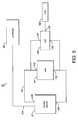
- FIG. 5is a schematic diagram illustrating one embodiment of an actuator control system which is adapted to monitor the temperature of an actuator coil of the drive of FIG. 1;
- FIG. 6is a flow chart illustrating one embodiment of a method of measuring the temperature of the coil used by the control system of FIG. 5;
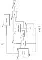
- FIG. 7is a schematic diagram illustrating another embodiment of the actuator control system of the drive of FIG. 1;
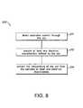
- FIG. 8is a flow chart illustrating one embodiment of a method of measuring the temperature of the coil used by the control system of FIG. 7;
- FIG. 9is a schematic diagram illustrating yet another embodiment of the actuator control system of the drive of FIG. 1;
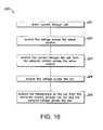
- FIG. 10is a flow chart illustrating one embodiment of a method of measuring the temperature of the coil used by the control system of FIG. 9;
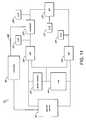
- FIG. 11is a schematic diagram illustrating still yet another embodiment of the actuator control system of the drive of FIG. 1;
- FIG. 12is a flow chart illustrating one embodiment of a method of measuring the temperature of the coil which can used by either the control system of FIG. 9 or the control system of FIG. 11 .
- FIG. 1schematically illustrates a hard disk drive 30 for storing information according to one aspect of the present invention.
- the hard disk drivecomprises a magnetic medium 32 having a plurality of magnetic domains 34 disposed therein such that the magnetization states of the domains 34 define the information stored on the hard disk drive 30 .
- the medium 32is preferably disposed on a disk-shaped member.
- the drive 30further comprises a transducer 36 for affecting and sensing the magnetization states of the magnetic domains 34 and an actuator 40 for disposing the transducer 36 adjacent the magnetic medium 32 and for moving the transducer 36 between positions adjacent the medium 32 .
- the actuator 40comprises a pivotally mounted actuator arm 42 coupled to the transducer 36 , an actuator coil 44 coupled to the actuator arm 42 , and a magnetic field source 46 , such as a permanent magnet, for exerting forces onto the coil 44 when current flows through the coil 44 .
- the arm 42is able to pivot in a plane parallel to a recording surface of the magnetic medium 32 such that the arm 42 is able to sweep across a substantial portion of the recording surface.
- the coil 44comprises a conducting wire wound into a plurality of loops and, thus, defines a conducting path 50 such that a current flowing through the conducting path 50 interacts with the magnetic field of the magnetic source 46 to exert forces onto the coil 44 .
- the actuator arm 42experiences a net torque in response to the current flowing through the coil 44 which angularly accelerates the actuator arm 42 and, thus, linearly accelerates the transducer 36 from an initial state of rest into a state of motion with respect to the field source 46 . Furthermore, in response to the coil current flowing in the opposite direction, the actuator arm 42 experiences a torque that subsequently brings the transducer 36 to a state of rest at a new position with respect the medium 32 .
- the simplified current profile illustrated in FIG. 2could be used to perform a seek operation so as to pivot the actuator arm 42 between first and second orientations.
- a forward currentis driven through the coil 44 starting at T 0 and ending at t 1 .
- the forward currentangularly accelerates the actuator arm 42 at a rate which is proportional to the amplitude of the forward current until the time t 1 such that the actuator arm 42 reaches a maximum angular speed.
- a reverse currentis driven through the coil 44 so as to decelerate the actuator arm 42 at a rate which is proportional to the amplitude of the reverse current until the reverse current is switched off at a time t 3 such that the actuator arm 42 is at rest and the transducer 36 is positioned substantially near a desired final position.
- the drive 30includes an inexpensive yet effective means for monitoring the temperature of the coil 44 so that the drive 30 can achieve high throughput rates when the temperature of the coil 44 is within an acceptable range and so that the rate of heat generation within the coil 44 can be limited when the temperature of the coil 44 is approaching the upper bounds of the acceptable range.
- the hard disk drive 30further comprises an actuator control system 52 for controlling the current that flows through the coil 44 .
- the control systemdetermines a desired current profile, such as that shown in FIG. 2, and directs current with the desired profile to flow through the coil 44 using techniques that are well known in the art during a normal mode of operation.
- the actuator control system 52includes a feature not found in the prior art that allows the actuator control system 52 to monitor the temperature of the coil 44 .
- the control system 52can assume an alarmed state whereby the control system 52 attempts to limit the current flowing through the coil so as to reduce the average rate of heat generated within the coil.
- the control system 52monitors the temperature of the coil by sampling at least one electrical characteristic of the conducting path 50 of the coil 44 which is indicative of the temperature of the actuator coil 44 .
- the at least one electrical characteristiccould be the current flowing through the coil 44 , the voltage applied across the coil 44 , or both.
- the conducting path 50could be further defined by a series component, such as a resistor, disposed in series with the coil 44 and the at least one electrical characteristic of the conducting path 50 could include the current flowing through the series component or the voltage across the series component.
- the purpose of sampling the at least one electrical characteristic of the conducting path 50is to obtain a measure of the resistance of the coil 44 . Because the resistance of the coil 44 is directly related to the temperature of the coil 44 , a measure of the temperature of the coil 44 can be obtained without requiring additional discrete temperature monitoring devices and without using mathematical modeling techniques.
- the sampling of the electrical characteristicspreferably occurs at a time when these components are either substantially small or at substantially unchanged values.
- the back emf componentis caused by the 44 changing magnetic flux through the winding of the coil 44 that results when the coil 44 is reoriented with respect to the magnetic field of the permanent magnets 46 .
- the back emf componentis zero if the actuator arm 42 is held motionless and non-zero while the actuator arm 42 is pivoting. Consequently, the back emf component can be substantially removed if the actuator arm 42 is held substantially motionless while the sampling is taking place.
- the back emf componentwill have a relatively small variation and, thus, will not substantially contribute to the variation in the voltage across the coil or the current through the coil 44 .
- the sampling of the electrical characteristicspreferably occurs at a time when the current through the coil 44 has a reduced rate of change. Because the current typically varies rapidly only during an initial brief period of time when the current is switched on, the effects of self-inductance can be greatly reduced if the sampling of the at least one electrical characteristic occurs at a delayed time with respect to the beginning of the commanded current.
- the hard disk drivefurther comprises a stop 54 for limiting the motion of the actuator arm 42 .
- the temperature of the coil 44is measured while the actuator arm 42 is held in a stationary state. This is accomplished by positioning the arm 42 adjacent the stop 54 in a substantially flush manner and by directing current through the coil 44 such that the arm 42 is forced against the stop 54 .
- directing current through the coil 44 while the arm 42 is held stationaryensures that the back emf component of the voltage across the coil 44 is essentially zero. Consequently, this allows the resistance of the coil 44 to be measured with greater accuracy.
- the actuator arm 42is not held in a stationary state when current is directed through the coil 44 . More particularly, the resistance and/or temperature of the coil 44 is monitored when the drive 30 is operated in a seek mode. To reduce the effects of the non-zero back emf component of the voltage across the coil, repeated samplings of the at least;one electrical characteristic of the conducting path defined by the coil 44 can occur when the back emf component is substantially the same value. Consequently, because this does not require making the drive 30 unavailable to a host computer during the temperature measuring process, the temperature of the coil 44 can be measured in a manner that does not substantially decrease the throughput of the drive 30 .
- the samplingscan occur at a time t d which is delayed by a fixed period ⁇ t with respect to the seek start time t 0 as shown in FIG. 2 . Because all samplings use the same sampling ⁇ t is used in subsequent samplings, it can be inferred that the actuator arm will always have substantially similar angular velocity during subsequent samplings. Thus, because the back emf component is proportional to the angular velocity, the back emf component will not change substantially from one sampling to the next.
- the samplingcan occur at a time when an independent measurement of the angular velocity is substantially equal to a predetermined fixed value.
- the velocity of the armcan be independently measured from servo position signals corresponding to the transducer passing pre-mapped servo sections of the medium.
- the back emf componentcan be removed by calculating the back emf component of the voltage across the coil using known techniques that can rely on the independently measured angular velocity of the arm. Thus by subtracting the calculated back emf component from the measured voltage across the coil, the resistive component of the voltage across the coil can be estimated.
- An advantage of this method of removing the back emf componentis that it does not require subsequent samplings to occur when the angular velocity of the actuator arm is substantially the same value.
- the drive 30comprises a hard disk assembly (HDA) 60 and a printed circuit board assembly (PCBA) 62 .
- the HDA 60includes a base 64 and a cover 66 attached to the base 66 that collectively houses at least one rotatably mounted magnetic disk 70 , a spindle motor 72 attached to the base 64 for rotating the mounted disk 70 , the actuator 40 , and the known transducer element 36 for converting electrical signals into a corresponding modulated magnetic field and for converting a modulated magnetic field into corresponding electrical signals.
- the preferred actuator 40is a swing-type or rotary actuator that includes a body portion 74 , at least one actuator arm 42 extending from the body portion 74 , and the coil portion 50 extending from the body portion 74 in an opposite direction from the actuator arm 42 .
- the coil portion 50comprises a conducting wire wound into a plurality of loops that forms a voice coil motor (VCM) when combined with one or more permanent magnets.
- VCMvoice coil motor
- the transducer element 36is coupled to a first end of the arm 42 so that the transducer 36 can be positioned adjacent a recording surface of the disk 70 at a first radius when the arm 42 is positioned over the disk 70 and so that the transducer 36 can be moved to a second radius by pivoting the arm 42 across the recording surface.
- the spindle motor 72rotates the disk 70 at a constant angular velocity so that, when the transducer 36 is maintained at a substantially fixed radial position, electrical signals originating from or terminating at the transducer 36 allow data to be retrieved or stored within a corresponding circular track of the disk 70 .
- electrical signalsare delivered to the PCBA 62 via a known flex cable 76 so as to enable the actuator arm 42 to pivot without obstruction.
- the storage capacity of the drive 30is increased by utilizing a plurality of overlapping disks 70 as shown in FIG. 3 .
- the disks 70are separately written to and read from a corresponding plurality of overlapping transducers which are separately supported by a corresponding plurality of overlapping actuator arms.
- the disk drive 30comprises a host interface and disk controller (HIDC) 81 , a read/write channel 82 , a servo controller 83 , a microprocessor 84 , and several memory arrays, including cache memory buffer 85 , random access memory (RAM) 86 , and non-volatile memory 87 .
- the HIDC 81comprises a disk controller 88 for formatting and providing error detection and correction of disk data, a host interface controller 89 for responding to commands from a host 90 , and a buffer controller 91 for storing data which is transferred between disks 70 and host 90 .
- the controllers in the HIDC 81provide automated functions that assist the microprocessor 84 in controlling disk operations.
- Host-initiated operations for reading and writing data in disk drive 30are executed under the control of the microprocessor 84 connected to the controllers and memory arrays via a bus 92 .
- Program code executed by microprocessor 84is stored in non-volatile memory 87 and RAM 86 .
- Program overlay code stored on reserved tracks of disks 70may also be loaded into RAM 86 as required for execution.
- the components of the drive 30 illustrated in FIG. 3are integrated into a single disk processor unit. However, it will be appreciated that, in another embodiment, the components of the drive 30 could be distributed among a plurality of integrated circuit packages.
- the transducers 36 of the driveare coupled to preamplifiers 93 via the flex cable 76 so as to amplify electrical signals originating from and terminating at the transducers 36 .
- the preamplifiers 93are connected to the read/write channel 82 via read data lines 94 and write data lines 95 .
- data transferred by preamplifiers 93is encoded and decoded by read/write channel 82 .
- channel 82decodes data into digital bits transferred on an NRZ bus 96 to HIDC 81 .
- the HIDC 81provides digital data over the NRZ bus 96 to channel 81 that encodes the data prior to its transmittal to preamplifier 93 .
- channel 93employs partial response maximum likelihood (PRML) coding techniques, although other coding processes could be used without departing from the spirit of the present invention.
- PRMLpartial response maximum likelihood
- the servo controller 83 , the microprocessor 84 , and a VCM driver 97collectively form one embodiment of the actuator control system 52 mentioned earlier in connection with FIG. 1 .
- the VCM driver 97is a known controllable source of current and is serially connected to the coil 44 so that the current flowing from the VCM driver 97 also flows through the coil 44 .
- the VCM driver 97is controlled by the servo controller 83 which is commanded by the microprocessor 84 .
- the microprocessor 84instructs the servo controller 83 to assume a seek mode of operation so as to reposition the transducer 36 at the requested track.
- the servo controller 83receives servo information from the transducer 36 as the transducer passes dedicated servo sections of the disk 70 so as to determine an updated position and velocity of the transducer 36 with respect to the disk 70 .
- the servo controller 83Using the updated position and velocity, the servo controller 83 repeatedly alters the motion of the transducer 36 by instructing the VCM driver 97 to generate an appropriate current to flow through the coil 44 so that the transducer 36 is subsequently displaced to the requested radial position.
- the control system 52monitors the temperature of the coil 44 in a manner that will be described in greater detail below and switches between first and second modes of operation accordingly.
- the actuator control system 52operates in the first mode such that a larger average current with respect to the average current of the second mode is driven through the coil 44 so as to improve the throughput of the drive.
- the actuator control system 52operates in the second mode such that a smaller average current with respect to the average current of the first mode is driven through the coil 44 so as to inhibit further heating of the coil 44 .
- control system 52 in the first modeprovides a command current having an increased amplitude so as to more rapidly accelerate the transducer 36 .
- control system 52 in the second modeprovides a command current having a decreased amplitude so as to reduce the instantaneous rate at which electrical energy is converted into heat within the coil 44 .
- control system 52 in the second modeincreases the dwell time or time between subsequent seeks so as to essentially reduce the average current flowing through the coil 44 and, therefore, reduce the average rate of heat generated within the coil 44 .
- FIG. 5illustrates one embodiment of the actuator control system 52 of the hard disk drive of FIG. 1 .
- the control system 52comprises a controller 98 , the commandable current source 97 , a difference unit 100 , and an analog to digital (A/D) converter unit 102 .
- the controller 98comprises the servo-controller 83 and microprocessor 84 of FIG. 4 .
- the controller 98is linked to the current source via a communication path 104 such that a commanded current value can be transmitted to the current source 97 across the communication path 104 .
- the current source 97receives the commanded current value from the controller 98 and generates a current corresponding to the commanded current value to flow between first and second outputs 106 and 108 of the current source 97 . More particularly, the current source 97 provides an output voltage across the outputs 106 , 108 which generates the output current with an amplitude equal to the commanded current value. However, if the required output voltage is greater than that which can be supplied by the current source 97 , the output voltage will become saturated and the resulting output current, known as the saturated output current, has a magnitude less than the commanded current value.
- first and second ends 110 and 112 of the VCM coil 44are electrically connected to the respective first and second outputs 106 , 108 of the current source 97 such that the conducting path 50 that is defined between the first and second outputs 106 , 108 of the current source 97 extends along the windings of the coil 44 . Consequently, current flowing from the outputs 106 , 108 of the current source 97 also flows through the coil 44 , thereby generating a torque onto the actuator arm 42 of FIG. 1 .
- the difference unit 100includes first and second inputs 114 and 116 electrically coupled to the respective ends 110 , 112 of the coil 44 and an output 118 electrically coupled to the A/D unit 102 .
- the difference unit 100generates an output signal from the output 118 which is indicative of the voltage applied across the inputs 116 , 118 .
- the difference unitcomprises a differential amplifier which is configured to have a gain of one.
- the AID unit 102samples, or digitizes, the output signal from the difference unit 100 and provides the controller 98 with access to the digitized value.
- FIG. 6illustrates one embodiment of a method 200 of measuring the coil temperature used by control system 52 of FIG. 5 .
- the controller 98in a state 201 , issues a commanded current value to the current source 97 which generates a current to flow through the coil 44 .
- the controller 98in a state 202 , then samples the voltage across the coil 44 by digitizing the output of the difference unit 102 while the current is flowing through the coil 44 .
- the current flowing through the coil 44is substantially the same during subsequent samplings so that changes in the sampled voltage across the coil 44 are not caused by changes in the current flowing through the coil 44 .
- changes in the sampled voltage across the coil 44are indicative of changes in the resistance of the coil 44 .
- the controller 98in a state 204 , then extracts the temperature of the coil 44 from the sampled voltage across the coil 44 .
- the controller 98extracts the temperature of the coil 44 using a lookup table stored in memory which is available to the controller 98 .
- the lookup tablecomprises a plurality of data points of pre-measured coil temperature vs. coil voltage.
- the data points of the lookup tablecan be generated by disposing the drive 30 in an environment having a known temperature, sampling the voltage across the coil 44 in the manner described above at the known temperature, changing the temperature of the environment, and repeating the sampling of the voltage across the coil 44 .
- the lookup tablereturns a single bit binary value indicating whether the temperature of the coil 44 is excessively high.
- a mathematical equationis fit to the pre-measured data points and the resulting fitted equation is used by the controller to extract the temperature of the coil 44 from the sampled voltage across the coil 44 .
- FIG. 7illustrates another embodiment of the actuator control system 52 of the hard disk drive 30 of FIG. 1 .
- the control system 52 of FIG. 7is similar to that of FIG. 5 in that it comprises the controller 98 and the commandable current source 97 .
- the control system of FIG. 7further comprises a sense resistor 120 having a precisely known resistance.
- the sense resistor 120is used to measured the current flowing through the coil 44 .
- the sense resistor 120is known to within one percent even though the coil resistance varies by as much as thirty percent due to the temperature of the coil 44 changing from 25 degrees Celsius to 85 degrees Celsius.
- the known value of the sense resistor 120is stored in a memory which is available to the controller 98 .
- the sense resistor 120is disposed in series with the coil 44 so that the conducting path 50 extending between the outputs 106 , 108 of the current source 97 further comprises the sense resistor 120 .
- the control system 52further comprises a difference unit 122 and an A/D unit 124 similar to those of FIG. 5 .
- the difference unit 122is configured to provide an output signal which is indicative of the voltage across the sense resistor 120 .
- the A/D converter 124 unitis configured to sample the output of the difference unit 122 and, thus, provide the controller 98 with a sampled value which is indicative of the voltage across the sense resistor 120 . Because the resistance of the sense resistor 120 is a relatively well known quantity, the controller 98 is able to divide the voltage across the sense resistor 120 by the known value of the resistance of the sense resistor 120 to obtain an accurate measurement of the current flowing through the sense resistor 120 . Furthermore, because the current flowing through the sense resistor 120 is essentially the same as the current flowing through the coil 44 , the controller 98 is provided with an accurate measurement of the current flowing through the coil 44 .
- control system 52 of FIG. 7further comprises a second difference unit 125 disposed so as to provide an output signal which is indicative of the output voltage of the current source 97 .
- the control system 52further comprises a second A/D converter 126 unit configured to sample the output of the second difference unit 125 and, provide the controller 98 with a measurement of the voltage across the outputs of the current source 97 .
- the purpose of the second difference unit 125 and second A/D unit 126is to enable the controller 98 to check to see whether the change in the voltage across the sense resistor 120 is, in part or in whole, due to a change in a supply voltage of the current source 97 .
- FIG. 8illustrates one embodiment of a method 210 of measuring the coil temperature used by the control system 52 of FIG. 7 .
- the controller 98in a state 211 , issues a commanded current value to the current source 97 which results in the output current being saturated. Because the saturated current provided by the current source 97 depends on the resistance of the conductive path 90 between the outputs 106 , 108 of the current source 97 , a change in the resistance of the coil 44 will affect the saturation current. Thus, by measuring the saturated current, an indication of the resistance of the coil 44 and, therefore, the temperature of the coil 44 can be obtained.
- the controller 98in a state 212 , then samples at least one electrical characteristic of the conducting path defined by the coil.
- the controllersamples the voltage across the sense resistor 120 by digitizing the output of the difference unit 125 while the saturated current is flowing through the coil 44 .
- the controlleralso samples the voltage across the current source 97 so as to determine if the current source 97 is experiencing a drop-off in output voltage.
- the controller 98in a state 214 , then extracts the temperature of the coil 44 from the at least one sampled electrical characteristic of the conducting path defined by the coil.
- the controller 98extracts a measurement of the saturated current flowing through the coil 44 from the sampled voltage across the sense resistor 120 by dividing the sampled voltage across the sense resistor 120 by the stored resistance of the sense resistor 120 . Because the saturated current flowing through the coil 44 is affected by the resistance of the coil 44 , the temperature of the coil 44 can be extracted from the saturated current using a predetermined lookup table or a pre-fitted equation.
- FIG. 9illustrates yet another embodiment of the actuator control system 52 of the hard disk drive 30 of FIG. 1 .
- the control system 52 of FIG. 9is similar to that of FIG. 7 in that it comprises the controller 98 , the commandable current source 97 , the sense resistor 120 , the difference units 122 and 125 and the A/D converter units 124 and 126 configured in a substantially identical manner.
- the second difference unit 125is configured to develop a signal which is indicative of the voltage across the coil 44 and the second A/D unit 126 is configured to sample the output of the second difference unit 125 so as to provide the controller 98 with the sample of the voltage across the coil 44 .
- FIG. 10illustrates one embodiment of a method 220 of measuring the coil temperature used by the control system 52 of FIG. 9 .
- the controller 98in a state 221 , instructs the current source 97 to generate a current to flow through the coil 44 .
- the controller 98in a state 222 , then samples the voltage across the sense resistor 120 while the current is flowing through the coil 44 .
- the controller 98in a state 223 , then uses the sampled voltage across the sense resistor 120 to extract a measurement of the current flowing through the coil 44 using the techniques described above in connection with FIG. 8 .
- the controller 98in a state 224 , then samples the voltage across the coil 44 while the current is flowing through the coil 44 . Then, in a state 225 , the controller 98 extracts the temperature of the coil 44 from the measured current flowing through the coil 44 and the sampled voltage across the coil 44 . In particular, the controller 98 calculates the resistance of the coil 44 by dividing the sampled voltage across the coil 44 by the measured current flowing through the coil 44 . The controller 98 then extracts the temperature of the coil 44 , for example, by using a predetermined lookup table that relates the measured resistance of the coil 44 to the temperature of the coil 44 .
- the controller 98measures both the current flowing through the coil 44 and the voltage across the coil 44 , it is not essential for the current to be saturated. However, because of the likely presence of electronic noise, it is sometimes advantageous to sample the electrical characteristics of the conducting path 50 while the current flowing through the coil 44 is relatively large. Thus, because the maximum current is the saturated current, it may be advantageous to direct saturated current through the coil 44 while measuring the temperature of the coil 44 .
- FIG. 11illustrates still yet another embodiment of the actuator control system 52 of the hard disk drive 30 of FIG. 1 .
- the control system 52 of FIG. 11comprises substantially the same control system described above in connection with FIG. 9 plus additional components for measuring the back emf component of the voltage across the coil 44 .
- the difference unit 122 coupled to the sense resistor 120includes a division function that divides the voltage across the sense resistor 120 by the resistance of the sense resistor 120 so that the output of the difference unit 122 is a voltage level scaled to be approximately equal to the current flowing through the coil 44 .
- the control system 52 of FIG. 11is based on an emergency parking system that maneuvers the actuator arm to a parked position in the event that power is removed from the hard disk drive.
- the control system 52further comprises an adjustable multiplier unit 127 which is configured to receive, as input, the output signal from the difference unit 122 which is indicative of the current flowing through the coil 44 and provide an output signal which is a voltage level approximately equal to the current flowing through the coil 44 times the resistance of the coil 44 , i.e. the resistive component of the voltage across the coil 44 .
- the multiplier 127is further configured to receive an adjustable multiplication factor over a communication path 128 from the controller 98 which is referenced by the multiplier 127 to perform the foregoing multiplication process.
- the difference between the output of the multiplier unit and the resistive component of the voltage across the coil 44is related to the closeness between the adjustable factor and the actual resistance of the coil 44 .
- the adjustable factoris successively adjusted by the controller 98 until a measured back emf value provided by the control system is approximately equal to an expected back emf value so as to enable fine tuning of the adjustable factor to, thereby, provide a relatively accurate measure of the resistance of the coil 44 .
- the adjustable multiplier unit 127comprises a multiplying digital to analog converter. Furthermore, the control system 52 further comprise a third A/D unit 129 configured to digitize the output signal of the multiplier unit 127 so as to provide the controller 98 with the digitized value of the estimated resistive component of the voltage across the coil 44 .
- the control systemfurther comprises a third difference unit 130 that receives: a) the output from the multiplier unit 127 which is indicative of the resistive component of the voltage across the coil 44 ; and b) the output from the second difference unit 125 which is indicative of the voltage across the coil 44 .
- the difference unit 130provides an output signal which is indicative of the difference between the voltage across the coil 44 and the resistive component of the voltage across the coil 44 .
- the control systemfurther comprises a fourth A/D unit 131 configured to digitize the output of the third difference unit 130 so as to provide the controller 98 with an estimate of the back emf component of the voltage across the coil 44 .
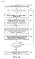
- FIG. 12illustrates a method 230 of measuring the temperature of the coil 44 of FIG. 1 according to one aspect of the present invention. As will be described in greater detail below, this method can be used in the context of the control system 52 of FIG. 9 or in the context of the control system 52 of FIG. 11 .
- the method 230comprises, in a state 231 , directing current to flow through the coil 44 .
- the method 230further comprises, in a state 232 , obtaining a measure of the voltage across the coil 44 and, in a state 233 , obtaining a measure of the current flowing through the coil 44 .
- the measured currentis then, in a state 234 , multiplied by an adjustable factor so as to obtain an estimate of the resistive component of the voltage across the coil 44 .
- the estimate of the resistive component of the voltage across the coil 44is then, in a state 235 , subtracted from the measured voltage across the coil 44 so as to obtain an estimate of the back emf component of the voltage across the coil 44 .
- the adjustable factoris then, in a state 236 , adjusted according to the difference between the estimated back emf component and the expected value so as to result in a reduced difference.
- a decision state 237the difference between the estimated back emf component and the expected value is compared with a difference threshold. If the difference is greater than the threshold the state 232 is reentered. However, if the difference is less than the threshold difference it is assumed that fine tuning of the adjustable factor has been achieved. Then, in a state 238 , the temperature of the coil is extracted from the adjustable factor.
- the temperature of the coil 44is extracted from the adjustable factor by first extracting an estimate of the resistance of the coil 44 from the adjustable factor. The temperature is then extracted from the estimated resistance using the techniques described earlier. The estimate of the resistance of the coil can be obtained by having the controller 98 divide the digitized estimate of the resistive component of the voltage across the coil 44 provided by the AD unit 129 by the digitized value of the current flowing through the coil provided by the A/D unit 124 . In another embodiment, the temperature of the coil 44 is extracted by applying the adjustable factor to a lookup table.
- the method 230 of FIG. 12is performed substantially by the hardware of the control system 52 as will how be described.
- the obtaining of the measures of the current through and voltage across the coil 44are performed by the respective difference units 122 and 125 with the measures being manifested within the output signals of the difference units 122 and 125 .
- the multiplying step of state 234is performed by the multiplier unit 127 and the subtraction step of state 235 is performed by the difference unit 130 .
- the adjusting step of state 236 , the comparison step of state 237 , and the extracting step of state 238are, in this embodiment, performed by the controller 98 .
- the method 230 of FIG. 12is performed substantially by software as will now be described.
- the obtaining of the measures of the current through and voltage across the coilare performed by the respective difference units 122 and 125 in combination with the A/D units 124 and 126 such that sampled values of the current and voltage are provided to the controller 98 . Because the controller 98 has access to the sampled values, the controller 98 is then able to perform the multiplying step of state 234 and the subtraction step of state 235 .
- the method of FIG. 12is performed while the actuator arm is maintained in a stationary state, such as by holding the actuator arm against the stop as described above in connection with FIG. 1 .
- the expected back emf valueis zero.
- the method of FIG. 12is performed during a seek operation such that the actuator arm is not maintained in a stationary state.
- the value of the back emf corresponding to a first sampling time t ais used as the expected value from which to compare with the value of the back emf corresponding to a subsequent second sampling, time, t b .
- the sampling times t a and t bare selected such that the current flowing through the coil at t a is substantially different from that of t b and the angular speed of the actuator arm at t a is substantially equal to that of t b .
- the angular velocities at times t a and t bare within five percent of each other.
- the angular velocity of the actuator armis extracted from transducer servo signals generated when the transducer passes dedicated servo regions on the disk.
- the first sampling time t acould correspond to the acceleration phase of the seek operation and second sampling time t b could correspond to the deceleration phase of the seek operation (see FIG. 2) such that the currents flowing through the coil at times t a and t b are in opposing direction.
- the first and second samplingsare obtained such that the current flowing through the coil at t a is in the same direction as in t b .
- the current flowing through the coil at t acould be twice as large as that current flowing through the coil at t b .
- the amplifiers of the difference units of FIGS. 9 and 11often include offset errors which fluctuates with temperature in an unpredictable manner.
- the difference unit 125 of FIG. 11may provide the output signal that corresponds to the voltage across the coil 44 plus a non-zero term corresponding to the offset error of the unit.
- the offset errorcan cancelled or reduced.
- the actuator control system and methods for providing the same described hereinprovide many advantages.
- the control systemis able to monitor the temperature of the coil, the control system is able to manipulate the transducer more rapidly when the temperature of the coil is not in danger of overheating so as to decrease the seek time of the hard disk drive.
- the control systemcan take corrective action to prevent any further heating of the coil. For example, the control system can limit the amplitude of the current flowing through the coil or increase the dwell time between seeks so as to allow the heat built up within the coil to dissipate to the environment.
- the methods of measuring the temperature of the actuator coil according to the present inventionprovide a more effective solution to the problem of excessive coil temperature than those known in the art.
- the temperatureis measured by sampling electrical characteristics of the coil which vary in a predictable manner in response to a change in coil temperature, the accuracy of the measurement is improved over methods which rely on theoretical models.
- thisobviates the need for a discrete temperature transducer and signal conditioning means, fewer discrete components are required, thereby enabling the hard disk drive to be manufactured at reduced cost.
- the methods of measuring the coil temperature disclosed hereinare able to utilize existing circuitry required for parking of the drive in the case of an unexpected power shutdown, the added expense to the drive, in this case, is essentially limited to the relatively small expense of developing additional software.
Landscapes
- Moving Of Head For Track Selection And Changing (AREA)
- Moving Of Heads (AREA)
Abstract
Description
Claims (8)
Priority Applications (1)
| Application Number | Priority Date | Filing Date | Title |
|---|---|---|---|
| US09/728,550US6731450B1 (en) | 2000-11-30 | 2000-11-30 | Disk drive control system and method for determining the temperature of an actuator coil |
Applications Claiming Priority (1)
| Application Number | Priority Date | Filing Date | Title |
|---|---|---|---|
| US09/728,550US6731450B1 (en) | 2000-11-30 | 2000-11-30 | Disk drive control system and method for determining the temperature of an actuator coil |
Publications (1)
| Publication Number | Publication Date |
|---|---|
| US6731450B1true US6731450B1 (en) | 2004-05-04 |
Family
ID=32177020
Family Applications (1)
| Application Number | Title | Priority Date | Filing Date |
|---|---|---|---|
| US09/728,550Expired - Fee RelatedUS6731450B1 (en) | 2000-11-30 | 2000-11-30 | Disk drive control system and method for determining the temperature of an actuator coil |
Country Status (1)
| Country | Link |
|---|---|
| US (1) | US6731450B1 (en) |
Cited By (119)
| Publication number | Priority date | Publication date | Assignee | Title |
|---|---|---|---|---|
| US20040080848A1 (en)* | 2002-09-18 | 2004-04-29 | Takayuki Ichihara | Magnetic recording apparatus and method of writing data |
| US20040124800A1 (en)* | 2002-12-27 | 2004-07-01 | Tanner Brian K. | Method for spindle bearing friction estimation for reliable disk drive startup operation |
| US20040257695A1 (en)* | 2003-06-19 | 2004-12-23 | Tan Leeling | Method and apparatus for measuring the back EMF of a disc drive VCM |
| US20050013037A1 (en)* | 2003-07-18 | 2005-01-20 | Brian Tanner | Direct detection of coil resistance |
| US7005820B2 (en)* | 2002-12-27 | 2006-02-28 | Matsushita Electric Industrial Co., Ltd. | Apparatus for spindle bearing friction estimation for reliable disk drive startup |
| US7203021B1 (en)* | 2005-11-15 | 2007-04-10 | Western Digital Technologies, Inc. | Self-heating disk drive |
| US7437502B1 (en) | 2005-04-20 | 2008-10-14 | Western Digital Technologies, Inc. | Disk drive adjusting operating mode based on historical proximity of host commands |
| US7450334B1 (en) | 2007-06-28 | 2008-11-11 | Western Digital Technologies, Inc. | Disk drive adjusting predictive caching based on temperature of voice coil motor |
| US7660067B1 (en) | 2007-09-19 | 2010-02-09 | Western Digital Technologies, Inc. | Disk drive initializing a coil temperature estimation algorithm using a resistance of the coil estimated during a load operation |
| US20100176759A1 (en)* | 2009-01-15 | 2010-07-15 | Sturman Industries, Inc. | Control Valve Coil Temperature Controller |
| US7800857B1 (en) | 2009-04-30 | 2010-09-21 | Western Digital Technologies, Inc. | Disk drive calibrating voice coil resistance for velocity control of voice coil motor |
| US7876522B1 (en) | 2008-09-30 | 2011-01-25 | Western Digital Technologies, Inc. | Disk drive updating estimate of voice coil resistance to account for resistance change prior to unload operation |
| US8090902B1 (en) | 2009-05-22 | 2012-01-03 | Western Digital Technologies, Inc. | Disk drive adjusting command execution in response to control circuitry die temperature |
| US8665551B1 (en) | 2011-12-22 | 2014-03-04 | Western Digital Technologies, Inc. | Disk drive adjusting gain and offset of BEMF velocity sensor during self writing of spiral tracks |
| US8824081B1 (en) | 2012-03-13 | 2014-09-02 | Western Digital Technologies, Inc. | Disk drive employing radially coherent reference pattern for servo burst demodulation and fly height measurement |
| US8830617B1 (en) | 2013-05-30 | 2014-09-09 | Western Digital Technologies, Inc. | Disk drive adjusting state estimator to compensate for unreliable servo data |
| US8879191B1 (en) | 2012-11-14 | 2014-11-04 | Western Digital Technologies, Inc. | Disk drive modifying rotational position optimization algorithm to achieve target performance for limited stroke |
| US8891194B1 (en) | 2013-05-14 | 2014-11-18 | Western Digital Technologies, Inc. | Disk drive iteratively adapting correction value that compensates for non-linearity of head |
| US8891191B1 (en) | 2014-05-06 | 2014-11-18 | Western Digital Technologies, Inc. | Data storage device initializing read signal gain to detect servo seed pattern |
| US8896957B1 (en) | 2013-05-10 | 2014-11-25 | Western Digital Technologies, Inc. | Disk drive performing spiral scan of disk surface to detect residual data |
| US8902538B1 (en) | 2013-03-29 | 2014-12-02 | Western Digital Technologies, Inc. | Disk drive detecting crack in microactuator |
| US8902539B1 (en) | 2014-05-13 | 2014-12-02 | Western Digital Technologies, Inc. | Data storage device reducing seek power consumption |
| US8913342B1 (en) | 2014-03-21 | 2014-12-16 | Western Digital Technologies, Inc. | Data storage device adjusting range of microactuator digital-to-analog converter based on operating temperature |
| US8917475B1 (en) | 2013-12-20 | 2014-12-23 | Western Digital Technologies, Inc. | Disk drive generating a disk locked clock using radial dependent timing feed-forward compensation |
| US8917474B1 (en) | 2011-08-08 | 2014-12-23 | Western Digital Technologies, Inc. | Disk drive calibrating a velocity profile prior to writing a spiral track |
| US8922938B1 (en) | 2012-11-02 | 2014-12-30 | Western Digital Technologies, Inc. | Disk drive filtering disturbance signal and error signal for adaptive feed-forward compensation |
| US8922931B1 (en) | 2013-05-13 | 2014-12-30 | Western Digital Technologies, Inc. | Disk drive releasing variable amount of buffered write data based on sliding window of predicted servo quality |
| US8922940B1 (en) | 2014-05-27 | 2014-12-30 | Western Digital Technologies, Inc. | Data storage device reducing spindle motor voltage boost during power failure |
| US8922937B1 (en) | 2012-04-19 | 2014-12-30 | Western Digital Technologies, Inc. | Disk drive evaluating multiple vibration sensor outputs to enable write-protection |
| US8929021B1 (en) | 2012-03-27 | 2015-01-06 | Western Digital Technologies, Inc. | Disk drive servo writing from spiral tracks using radial dependent timing feed-forward compensation |
| US8929022B1 (en) | 2012-12-19 | 2015-01-06 | Western Digital Technologies, Inc. | Disk drive detecting microactuator degradation by evaluating frequency component of servo signal |
| US8934186B1 (en) | 2014-03-26 | 2015-01-13 | Western Digital Technologies, Inc. | Data storage device estimating servo zone to reduce size of track address |
| US8937784B1 (en) | 2012-08-01 | 2015-01-20 | Western Digital Technologies, Inc. | Disk drive employing feed-forward compensation and phase shift compensation during seek settling |
| US8941939B1 (en) | 2013-10-24 | 2015-01-27 | Western Digital Technologies, Inc. | Disk drive using VCM BEMF feed-forward compensation to write servo data to a disk |
| US8941945B1 (en) | 2014-06-06 | 2015-01-27 | Western Digital Technologies, Inc. | Data storage device servoing heads based on virtual servo tracks |
| US8947819B1 (en) | 2012-08-28 | 2015-02-03 | Western Digital Technologies, Inc. | Disk drive implementing hysteresis for primary shock detector based on a more sensitive secondary shock detector |
| US8953278B1 (en) | 2011-11-16 | 2015-02-10 | Western Digital Technologies, Inc. | Disk drive selecting disturbance signal for feed-forward compensation |
| US8953271B1 (en) | 2013-05-13 | 2015-02-10 | Western Digital Technologies, Inc. | Disk drive compensating for repeatable run out selectively per zone |
| US8958169B1 (en) | 2014-06-11 | 2015-02-17 | Western Digital Technologies, Inc. | Data storage device re-qualifying state estimator while decelerating head |
| US8970979B1 (en) | 2013-12-18 | 2015-03-03 | Western Digital Technologies, Inc. | Disk drive determining frequency response of actuator near servo sample frequency |
| US8982501B1 (en) | 2014-09-22 | 2015-03-17 | Western Digital Technologies, Inc. | Data storage device compensating for repeatable disturbance when commutating a spindle motor |
| US8982490B1 (en) | 2014-04-24 | 2015-03-17 | Western Digital Technologies, Inc. | Data storage device reading first spiral track while simultaneously writing second spiral track |
| US8995075B1 (en) | 2012-06-21 | 2015-03-31 | Western Digital Technologies, Inc. | Disk drive adjusting estimated servo state to compensate for transient when crossing a servo zone boundary |
| US8995082B1 (en) | 2011-06-03 | 2015-03-31 | Western Digital Technologies, Inc. | Reducing acoustic noise in a disk drive when exiting idle mode |
| US9001454B1 (en) | 2013-04-12 | 2015-04-07 | Western Digital Technologies, Inc. | Disk drive adjusting phase of adaptive feed-forward controller when reconfiguring servo loop |
| US9007714B1 (en) | 2014-07-18 | 2015-04-14 | Western Digital Technologies Inc. | Data storage device comprising slew rate anti-windup compensation for microactuator |
| US9013825B1 (en) | 2014-03-24 | 2015-04-21 | Western Digital Technologies, Inc. | Electronic system with vibration management mechanism and method of operation thereof |
| US9013824B1 (en) | 2014-06-04 | 2015-04-21 | Western Digital Technologies, Inc. | Data storage device comprising dual read sensors and dual servo channels to improve servo demodulation |
| US9026728B1 (en) | 2013-06-06 | 2015-05-05 | Western Digital Technologies, Inc. | Disk drive applying feed-forward compensation when writing consecutive data tracks |
| US9025269B1 (en) | 2014-01-02 | 2015-05-05 | Western Digital Technologies, Inc. | Disk drive compensating for cycle slip of disk locked clock when reading mini-wedge |
| US9047901B1 (en) | 2013-05-28 | 2015-06-02 | Western Digital Technologies, Inc. | Disk drive measuring spiral track error by measuring a slope of a spiral track across a disk radius |
| US9047919B1 (en) | 2013-03-12 | 2015-06-02 | Western Digitial Technologies, Inc. | Disk drive initializing servo read channel by reading data preceding servo preamble during access operation |
| US9047932B1 (en) | 2014-03-21 | 2015-06-02 | Western Digital Technologies, Inc. | Data storage device adjusting a power loss threshold based on samples of supply voltage |
| US9053712B1 (en) | 2014-05-07 | 2015-06-09 | Western Digital Technologies, Inc. | Data storage device reading servo sector while writing data sector |
| US9053727B1 (en) | 2014-06-02 | 2015-06-09 | Western Digital Technologies, Inc. | Disk drive opening spiral crossing window based on DC and AC spiral track error |
| US9053726B1 (en) | 2014-01-29 | 2015-06-09 | Western Digital Technologies, Inc. | Data storage device on-line adapting disturbance observer filter |
| US9058827B1 (en) | 2013-06-25 | 2015-06-16 | Western Digitial Technologies, Inc. | Disk drive optimizing filters based on sensor signal and disturbance signal for adaptive feed-forward compensation |
| US9058834B1 (en) | 2013-11-08 | 2015-06-16 | Western Digital Technologies, Inc. | Power architecture for low power modes in storage devices |
| US9058826B1 (en) | 2014-02-13 | 2015-06-16 | Western Digital Technologies, Inc. | Data storage device detecting free fall condition from disk speed variations |
| US9064537B1 (en) | 2013-09-13 | 2015-06-23 | Western Digital Technologies, Inc. | Disk drive measuring radial offset between heads by detecting a difference between ramp contact |
| US9076471B1 (en) | 2013-07-31 | 2015-07-07 | Western Digital Technologies, Inc. | Fall detection scheme using FFS |
| US9076473B1 (en) | 2014-08-12 | 2015-07-07 | Western Digital Technologies, Inc. | Data storage device detecting fly height instability of head during load operation based on microactuator response |
| US9076490B1 (en) | 2012-12-12 | 2015-07-07 | Western Digital Technologies, Inc. | Disk drive writing radial offset spiral servo tracks by reading spiral seed tracks |
| US9076472B1 (en) | 2014-08-21 | 2015-07-07 | Western Digital (Fremont), Llc | Apparatus enabling writing servo data when disk reaches target rotation speed |
| US9093105B2 (en) | 2011-12-09 | 2015-07-28 | Western Digital Technologies, Inc. | Disk drive charging capacitor using motor supply voltage during power failure |
| US9099147B1 (en) | 2014-09-22 | 2015-08-04 | Western Digital Technologies, Inc. | Data storage device commutating a spindle motor using closed-loop rotation phase alignment |
| US9111575B1 (en) | 2014-10-23 | 2015-08-18 | Western Digital Technologies, Inc. | Data storage device employing adaptive feed-forward control in timing loop to compensate for vibration |
| US9129630B1 (en) | 2014-12-16 | 2015-09-08 | Western Digital Technologies, Inc. | Data storage device employing full servo sectors on first disk surface and mini servo sectors on second disk surface |
| US9142225B1 (en) | 2014-03-21 | 2015-09-22 | Western Digital Technologies, Inc. | Electronic system with actuator control mechanism and method of operation thereof |
| US9142235B1 (en) | 2009-10-27 | 2015-09-22 | Western Digital Technologies, Inc. | Disk drive characterizing microactuator by injecting sinusoidal disturbance and evaluating feed-forward compensation values |
| US9141177B1 (en) | 2014-03-21 | 2015-09-22 | Western Digital Technologies, Inc. | Data storage device employing glitch compensation for power loss detection |
| US9142249B1 (en) | 2013-12-06 | 2015-09-22 | Western Digital Technologies, Inc. | Disk drive using timing loop control signal for vibration compensation in servo loop |
| US9147428B1 (en) | 2013-04-24 | 2015-09-29 | Western Digital Technologies, Inc. | Disk drive with improved spin-up control |
| US9147418B1 (en) | 2013-06-20 | 2015-09-29 | Western Digital Technologies, Inc. | Disk drive compensating for microactuator gain variations |
| US9153283B1 (en) | 2014-09-30 | 2015-10-06 | Western Digital Technologies, Inc. | Data storage device compensating for hysteretic response of microactuator |
| US9165583B1 (en) | 2014-10-29 | 2015-10-20 | Western Digital Technologies, Inc. | Data storage device adjusting seek profile based on seek length when ending track is near ramp |
| US9171568B1 (en) | 2014-06-25 | 2015-10-27 | Western Digital Technologies, Inc. | Data storage device periodically re-initializing spindle motor commutation sequence based on timing data |
| US9171567B1 (en) | 2014-05-27 | 2015-10-27 | Western Digital Technologies, Inc. | Data storage device employing sliding mode control of spindle motor |
| US9208815B1 (en) | 2014-10-09 | 2015-12-08 | Western Digital Technologies, Inc. | Data storage device dynamically reducing coast velocity during seek to reduce power consumption |
| US9208808B1 (en) | 2014-04-22 | 2015-12-08 | Western Digital Technologies, Inc. | Electronic system with unload management mechanism and method of operation thereof |
| US9208810B1 (en) | 2014-04-24 | 2015-12-08 | Western Digital Technologies, Inc. | Data storage device attenuating interference from first spiral track when reading second spiral track |
| US9214175B1 (en) | 2015-03-16 | 2015-12-15 | Western Digital Technologies, Inc. | Data storage device configuring a gain of a servo control system for actuating a head over a disk |
| US9230593B1 (en) | 2014-12-23 | 2016-01-05 | Western Digital Technologies, Inc. | Data storage device optimizing spindle motor power when transitioning into a power failure mode |
| US9230592B1 (en) | 2014-12-23 | 2016-01-05 | Western Digital Technologies, Inc. | Electronic system with a method of motor spindle bandwidth estimation and calibration thereof |
| US9245577B1 (en) | 2015-03-26 | 2016-01-26 | Western Digital Technologies, Inc. | Data storage device comprising spindle motor current sensing with supply voltage noise attenuation |
| US9245560B1 (en) | 2015-03-09 | 2016-01-26 | Western Digital Technologies, Inc. | Data storage device measuring reader/writer offset by reading spiral track and concentric servo sectors |
| US9245540B1 (en) | 2014-10-29 | 2016-01-26 | Western Digital Technologies, Inc. | Voice coil motor temperature sensing circuit to reduce catastrophic failure due to voice coil motor coil shorting to ground |
| US9251823B1 (en) | 2014-12-10 | 2016-02-02 | Western Digital Technologies, Inc. | Data storage device delaying seek operation to avoid thermal asperities |
| US9269386B1 (en) | 2014-01-29 | 2016-02-23 | Western Digital Technologies, Inc. | Data storage device on-line adapting disturbance observer filter |
| US9286925B1 (en) | 2015-03-26 | 2016-03-15 | Western Digital Technologies, Inc. | Data storage device writing multiple burst correction values at the same radial location |
| US9286927B1 (en) | 2014-12-16 | 2016-03-15 | Western Digital Technologies, Inc. | Data storage device demodulating servo burst by computing slope of intermediate integration points |
| US9343094B1 (en) | 2015-03-26 | 2016-05-17 | Western Digital Technologies, Inc. | Data storage device filtering burst correction values before downsampling the burst correction values |
| US9343102B1 (en) | 2015-03-25 | 2016-05-17 | Western Digital Technologies, Inc. | Data storage device employing a phase offset to generate power from a spindle motor during a power failure |
| US9350278B1 (en) | 2014-06-13 | 2016-05-24 | Western Digital Technologies, Inc. | Circuit technique to integrate voice coil motor support elements |
| US9349401B1 (en) | 2014-07-24 | 2016-05-24 | Western Digital Technologies, Inc. | Electronic system with media scan mechanism and method of operation thereof |
| US9355667B1 (en) | 2014-11-11 | 2016-05-31 | Western Digital Technologies, Inc. | Data storage device saving absolute position at each servo wedge for previous write operations |
| US9355676B1 (en) | 2015-03-25 | 2016-05-31 | Western Digital Technologies, Inc. | Data storage device controlling amplitude and phase of driving voltage to generate power from a spindle motor |
| US9361939B1 (en) | 2014-03-10 | 2016-06-07 | Western Digital Technologies, Inc. | Data storage device characterizing geometry of magnetic transitions |
| US9396751B1 (en) | 2015-06-26 | 2016-07-19 | Western Digital Technologies, Inc. | Data storage device compensating for fabrication tolerances when measuring spindle motor current |
| US9407015B1 (en) | 2014-12-29 | 2016-08-02 | Western Digital Technologies, Inc. | Automatic power disconnect device |
| US9418689B2 (en) | 2014-10-09 | 2016-08-16 | Western Digital Technologies, Inc. | Data storage device generating an operating seek time profile as a function of a base seek time profile |
| US9424868B1 (en) | 2015-05-12 | 2016-08-23 | Western Digital Technologies, Inc. | Data storage device employing spindle motor driving profile during seek to improve power performance |
| US9424871B1 (en) | 2012-09-13 | 2016-08-23 | Western Digital Technologies, Inc. | Disk drive correcting an error in a detected gray code |
| US9437237B1 (en) | 2015-02-20 | 2016-09-06 | Western Digital Technologies, Inc. | Method to detect power loss through data storage device spindle speed |
| US9437231B1 (en) | 2015-09-25 | 2016-09-06 | Western Digital Technologies, Inc. | Data storage device concurrently controlling and sensing a secondary actuator for actuating a head over a disk |
| US9454212B1 (en) | 2014-12-08 | 2016-09-27 | Western Digital Technologies, Inc. | Wakeup detector |
| US9471072B1 (en) | 2013-11-14 | 2016-10-18 | Western Digital Technologies, Inc | Self-adaptive voltage scaling |
| US9484733B1 (en) | 2013-09-11 | 2016-11-01 | Western Digital Technologies, Inc. | Power control module for data storage device |
| US9542966B1 (en) | 2015-07-09 | 2017-01-10 | Western Digital Technologies, Inc. | Data storage devices and methods with frequency-shaped sliding mode control |
| US9564162B1 (en) | 2015-12-28 | 2017-02-07 | Western Digital Technologies, Inc. | Data storage device measuring resonant frequency of a shock sensor by applying differential excitation and measuring oscillation |
| US9581978B1 (en) | 2014-12-17 | 2017-02-28 | Western Digital Technologies, Inc. | Electronic system with servo management mechanism and method of operation thereof |
| US9620160B1 (en) | 2015-12-28 | 2017-04-11 | Western Digital Technologies, Inc. | Data storage device measuring resonant frequency of a shock sensor by inserting the shock sensor into an oscillator circuit |
| US9823294B1 (en) | 2013-10-29 | 2017-11-21 | Western Digital Technologies, Inc. | Negative voltage testing methodology and tester |
| US9886285B2 (en) | 2015-03-31 | 2018-02-06 | Western Digital Technologies, Inc. | Communication interface initialization |
| US9899834B1 (en) | 2015-11-18 | 2018-02-20 | Western Digital Technologies, Inc. | Power control module using protection circuit for regulating backup voltage to power load during power fault |
| US9959204B1 (en) | 2015-03-09 | 2018-05-01 | Western Digital Technologies, Inc. | Tracking sequential ranges of non-ordered data |
| US20190310121A1 (en)* | 2016-07-20 | 2019-10-10 | Micro Motion, Inc. | Method for performing temperature compensation of maximum sensor current and test tone amplitude during meter verification |
| US20220094298A1 (en)* | 2020-09-22 | 2022-03-24 | Lennox Industries Inc. | Motor driver controller analysis device |
| CN114268208A (en)* | 2020-10-01 | 2022-04-01 | 日本电产三协株式会社 | Actuator |
Citations (16)
| Publication number | Priority date | Publication date | Assignee | Title |
|---|---|---|---|---|
| US5015937A (en)* | 1989-10-26 | 1991-05-14 | Siemens-Bendix Automotive Electronics L.P. | Parametric current control for microstepping unipolar motor |
| US5119250A (en)* | 1990-06-15 | 1992-06-02 | International Business Machines Corporation | Method and apparatus for performing a seek |
| US5128813A (en)* | 1990-06-21 | 1992-07-07 | Quantum Corporation | Thermal compensated head positioner servo for disk drive |
| US5566077A (en)* | 1992-05-29 | 1996-10-15 | International Business Machines Corporation | Media and optical drive operating temperature control system and method |
| US5594603A (en)* | 1993-12-02 | 1997-01-14 | Fujitsu Limited | Seek control system based upon a detected temperature of a positioning mechanism in a disk device |
| US5654840A (en)* | 1994-06-30 | 1997-08-05 | Western Digital Corporation | Hard disk drive which uses the back EMF of the actuator to detect shocks |
| US5726835A (en) | 1996-07-26 | 1998-03-10 | Western Digital Corporation | Disk drive actuator coil with reduced outgassing characteristics |
| US5768045A (en) | 1995-12-20 | 1998-06-16 | Western Digital Corporation | Hardware velocity limit control system |
| US5781363A (en)* | 1996-10-15 | 1998-07-14 | International Business Machines Corporation | Servo-free velocity estimator for coil driven actuator arm in a data storage drive |
| US5793558A (en) | 1996-06-05 | 1998-08-11 | Western Digital Corporation | Method for seek time optimization employing voice-coil motor current saturation level to define an adaptive deceleration profile |
| US5808438A (en)* | 1996-10-04 | 1998-09-15 | Texas Instruments Incorporated | Method and system for limiting current in a read/write head retract circuit |
| US5889629A (en) | 1996-06-27 | 1999-03-30 | Western Digital Corporation | Method and apparatus for controlling disk drive head parking during power interruption |
| US6163430A (en)* | 1996-07-18 | 2000-12-19 | Seagate Technology Llc | Disc drive positioning system with variable deceleration curve |
| US6342985B1 (en)* | 1998-09-15 | 2002-01-29 | International Business Machines Corporation | Method and apparatus for improving disk drive seek performance |
| US6369972B1 (en)* | 1999-05-14 | 2002-04-09 | Western Digital Technologies, Inc. | Temperature monitoring method of a disk drive voice coil motor from a traveled distance |
| US6594106B1 (en)* | 1999-10-29 | 2003-07-15 | International Business Machines Corporation | Adaptive servo estimator and compensator for coil and carriage deformation in voice coil motor driven hard disk drive |
- 2000
- 2000-11-30USUS09/728,550patent/US6731450B1/ennot_activeExpired - Fee Related
Patent Citations (16)
| Publication number | Priority date | Publication date | Assignee | Title |
|---|---|---|---|---|
| US5015937A (en)* | 1989-10-26 | 1991-05-14 | Siemens-Bendix Automotive Electronics L.P. | Parametric current control for microstepping unipolar motor |
| US5119250A (en)* | 1990-06-15 | 1992-06-02 | International Business Machines Corporation | Method and apparatus for performing a seek |
| US5128813A (en)* | 1990-06-21 | 1992-07-07 | Quantum Corporation | Thermal compensated head positioner servo for disk drive |
| US5566077A (en)* | 1992-05-29 | 1996-10-15 | International Business Machines Corporation | Media and optical drive operating temperature control system and method |
| US5594603A (en)* | 1993-12-02 | 1997-01-14 | Fujitsu Limited | Seek control system based upon a detected temperature of a positioning mechanism in a disk device |
| US5654840A (en)* | 1994-06-30 | 1997-08-05 | Western Digital Corporation | Hard disk drive which uses the back EMF of the actuator to detect shocks |
| US5768045A (en) | 1995-12-20 | 1998-06-16 | Western Digital Corporation | Hardware velocity limit control system |
| US5793558A (en) | 1996-06-05 | 1998-08-11 | Western Digital Corporation | Method for seek time optimization employing voice-coil motor current saturation level to define an adaptive deceleration profile |
| US5889629A (en) | 1996-06-27 | 1999-03-30 | Western Digital Corporation | Method and apparatus for controlling disk drive head parking during power interruption |
| US6163430A (en)* | 1996-07-18 | 2000-12-19 | Seagate Technology Llc | Disc drive positioning system with variable deceleration curve |
| US5726835A (en) | 1996-07-26 | 1998-03-10 | Western Digital Corporation | Disk drive actuator coil with reduced outgassing characteristics |
| US5808438A (en)* | 1996-10-04 | 1998-09-15 | Texas Instruments Incorporated | Method and system for limiting current in a read/write head retract circuit |
| US5781363A (en)* | 1996-10-15 | 1998-07-14 | International Business Machines Corporation | Servo-free velocity estimator for coil driven actuator arm in a data storage drive |
| US6342985B1 (en)* | 1998-09-15 | 2002-01-29 | International Business Machines Corporation | Method and apparatus for improving disk drive seek performance |
| US6369972B1 (en)* | 1999-05-14 | 2002-04-09 | Western Digital Technologies, Inc. | Temperature monitoring method of a disk drive voice coil motor from a traveled distance |
| US6594106B1 (en)* | 1999-10-29 | 2003-07-15 | International Business Machines Corporation | Adaptive servo estimator and compensator for coil and carriage deformation in voice coil motor driven hard disk drive |
Non-Patent Citations (1)
| Title |
|---|
| Raffi Codilian & Samuel K. Woo; Voice Coil Motor Thermal Resistance In Hard Disk Drives; Western Digital Corp.; Irvine, California. |
Cited By (130)
| Publication number | Priority date | Publication date | Assignee | Title |
|---|---|---|---|---|
| US20040080848A1 (en)* | 2002-09-18 | 2004-04-29 | Takayuki Ichihara | Magnetic recording apparatus and method of writing data |
| US7031091B2 (en)* | 2002-09-18 | 2006-04-18 | Hitachi, Ltd. | Magnetic recording apparatus and method of writing data at low temperature |
| US7009354B2 (en)* | 2002-12-27 | 2006-03-07 | Matsushita Electric Industrial Co., Ltd. | Method for spindle bearing friction estimation for reliable disk drive startup operation |
| US20040124800A1 (en)* | 2002-12-27 | 2004-07-01 | Tanner Brian K. | Method for spindle bearing friction estimation for reliable disk drive startup operation |
| US7005820B2 (en)* | 2002-12-27 | 2006-02-28 | Matsushita Electric Industrial Co., Ltd. | Apparatus for spindle bearing friction estimation for reliable disk drive startup |
| US20040257695A1 (en)* | 2003-06-19 | 2004-12-23 | Tan Leeling | Method and apparatus for measuring the back EMF of a disc drive VCM |
| US6937427B2 (en)* | 2003-06-19 | 2005-08-30 | Seagate Technology Llc | Method and apparatus for measuring the back EMF of a disc drive VCM |
| US6917486B2 (en)* | 2003-07-18 | 2005-07-12 | Matsushita Electrical Industrial Co., Ltd. | Direct detection of coil resistance |
| US20050013037A1 (en)* | 2003-07-18 | 2005-01-20 | Brian Tanner | Direct detection of coil resistance |
| US7437502B1 (en) | 2005-04-20 | 2008-10-14 | Western Digital Technologies, Inc. | Disk drive adjusting operating mode based on historical proximity of host commands |
| US7203021B1 (en)* | 2005-11-15 | 2007-04-10 | Western Digital Technologies, Inc. | Self-heating disk drive |
| US7450334B1 (en) | 2007-06-28 | 2008-11-11 | Western Digital Technologies, Inc. | Disk drive adjusting predictive caching based on temperature of voice coil motor |
| US7660067B1 (en) | 2007-09-19 | 2010-02-09 | Western Digital Technologies, Inc. | Disk drive initializing a coil temperature estimation algorithm using a resistance of the coil estimated during a load operation |
| US7876522B1 (en) | 2008-09-30 | 2011-01-25 | Western Digital Technologies, Inc. | Disk drive updating estimate of voice coil resistance to account for resistance change prior to unload operation |
| US8339762B2 (en)* | 2009-01-15 | 2012-12-25 | Sturman Industries, Inc. | Control valve coil temperature controller |
| US20100176759A1 (en)* | 2009-01-15 | 2010-07-15 | Sturman Industries, Inc. | Control Valve Coil Temperature Controller |
| US7800857B1 (en) | 2009-04-30 | 2010-09-21 | Western Digital Technologies, Inc. | Disk drive calibrating voice coil resistance for velocity control of voice coil motor |
| US8090902B1 (en) | 2009-05-22 | 2012-01-03 | Western Digital Technologies, Inc. | Disk drive adjusting command execution in response to control circuitry die temperature |
| US9142235B1 (en) | 2009-10-27 | 2015-09-22 | Western Digital Technologies, Inc. | Disk drive characterizing microactuator by injecting sinusoidal disturbance and evaluating feed-forward compensation values |
| US8995082B1 (en) | 2011-06-03 | 2015-03-31 | Western Digital Technologies, Inc. | Reducing acoustic noise in a disk drive when exiting idle mode |
| US8917474B1 (en) | 2011-08-08 | 2014-12-23 | Western Digital Technologies, Inc. | Disk drive calibrating a velocity profile prior to writing a spiral track |
| US8953278B1 (en) | 2011-11-16 | 2015-02-10 | Western Digital Technologies, Inc. | Disk drive selecting disturbance signal for feed-forward compensation |
| US9093105B2 (en) | 2011-12-09 | 2015-07-28 | Western Digital Technologies, Inc. | Disk drive charging capacitor using motor supply voltage during power failure |
| US9390749B2 (en) | 2011-12-09 | 2016-07-12 | Western Digital Technologies, Inc. | Power failure management in disk drives |
| US8665551B1 (en) | 2011-12-22 | 2014-03-04 | Western Digital Technologies, Inc. | Disk drive adjusting gain and offset of BEMF velocity sensor during self writing of spiral tracks |
| US8824081B1 (en) | 2012-03-13 | 2014-09-02 | Western Digital Technologies, Inc. | Disk drive employing radially coherent reference pattern for servo burst demodulation and fly height measurement |
| US8934191B1 (en) | 2012-03-27 | 2015-01-13 | Western Digital Technologies, Inc. | Disk drive generating a disk locked clock using radial dependent timing feed-forward compensation |
| US8929021B1 (en) | 2012-03-27 | 2015-01-06 | Western Digital Technologies, Inc. | Disk drive servo writing from spiral tracks using radial dependent timing feed-forward compensation |
| US8922937B1 (en) | 2012-04-19 | 2014-12-30 | Western Digital Technologies, Inc. | Disk drive evaluating multiple vibration sensor outputs to enable write-protection |
| US9454989B1 (en) | 2012-06-21 | 2016-09-27 | Western Digital Technologies, Inc. | Disk drive adjusting estimated servo state to compensate for transient when crossing a servo zone boundary |
| US8995075B1 (en) | 2012-06-21 | 2015-03-31 | Western Digital Technologies, Inc. | Disk drive adjusting estimated servo state to compensate for transient when crossing a servo zone boundary |
| US8937784B1 (en) | 2012-08-01 | 2015-01-20 | Western Digital Technologies, Inc. | Disk drive employing feed-forward compensation and phase shift compensation during seek settling |
| US8947819B1 (en) | 2012-08-28 | 2015-02-03 | Western Digital Technologies, Inc. | Disk drive implementing hysteresis for primary shock detector based on a more sensitive secondary shock detector |
| US9424871B1 (en) | 2012-09-13 | 2016-08-23 | Western Digital Technologies, Inc. | Disk drive correcting an error in a detected gray code |
| US8922938B1 (en) | 2012-11-02 | 2014-12-30 | Western Digital Technologies, Inc. | Disk drive filtering disturbance signal and error signal for adaptive feed-forward compensation |
| US8879191B1 (en) | 2012-11-14 | 2014-11-04 | Western Digital Technologies, Inc. | Disk drive modifying rotational position optimization algorithm to achieve target performance for limited stroke |
| US9076490B1 (en) | 2012-12-12 | 2015-07-07 | Western Digital Technologies, Inc. | Disk drive writing radial offset spiral servo tracks by reading spiral seed tracks |
| US8929022B1 (en) | 2012-12-19 | 2015-01-06 | Western Digital Technologies, Inc. | Disk drive detecting microactuator degradation by evaluating frequency component of servo signal |
| US9047919B1 (en) | 2013-03-12 | 2015-06-02 | Western Digitial Technologies, Inc. | Disk drive initializing servo read channel by reading data preceding servo preamble during access operation |
| US8902538B1 (en) | 2013-03-29 | 2014-12-02 | Western Digital Technologies, Inc. | Disk drive detecting crack in microactuator |
| US9001454B1 (en) | 2013-04-12 | 2015-04-07 | Western Digital Technologies, Inc. | Disk drive adjusting phase of adaptive feed-forward controller when reconfiguring servo loop |
| US9147428B1 (en) | 2013-04-24 | 2015-09-29 | Western Digital Technologies, Inc. | Disk drive with improved spin-up control |
| US8896957B1 (en) | 2013-05-10 | 2014-11-25 | Western Digital Technologies, Inc. | Disk drive performing spiral scan of disk surface to detect residual data |
| US8922931B1 (en) | 2013-05-13 | 2014-12-30 | Western Digital Technologies, Inc. | Disk drive releasing variable amount of buffered write data based on sliding window of predicted servo quality |
| US8953271B1 (en) | 2013-05-13 | 2015-02-10 | Western Digital Technologies, Inc. | Disk drive compensating for repeatable run out selectively per zone |
| US8891194B1 (en) | 2013-05-14 | 2014-11-18 | Western Digital Technologies, Inc. | Disk drive iteratively adapting correction value that compensates for non-linearity of head |
| US9047901B1 (en) | 2013-05-28 | 2015-06-02 | Western Digital Technologies, Inc. | Disk drive measuring spiral track error by measuring a slope of a spiral track across a disk radius |
| US8830617B1 (en) | 2013-05-30 | 2014-09-09 | Western Digital Technologies, Inc. | Disk drive adjusting state estimator to compensate for unreliable servo data |
| US9026728B1 (en) | 2013-06-06 | 2015-05-05 | Western Digital Technologies, Inc. | Disk drive applying feed-forward compensation when writing consecutive data tracks |
| US9147418B1 (en) | 2013-06-20 | 2015-09-29 | Western Digital Technologies, Inc. | Disk drive compensating for microactuator gain variations |
| US9058827B1 (en) | 2013-06-25 | 2015-06-16 | Western Digitial Technologies, Inc. | Disk drive optimizing filters based on sensor signal and disturbance signal for adaptive feed-forward compensation |
| US9076471B1 (en) | 2013-07-31 | 2015-07-07 | Western Digital Technologies, Inc. | Fall detection scheme using FFS |
| US9484733B1 (en) | 2013-09-11 | 2016-11-01 | Western Digital Technologies, Inc. | Power control module for data storage device |
| US9064537B1 (en) | 2013-09-13 | 2015-06-23 | Western Digital Technologies, Inc. | Disk drive measuring radial offset between heads by detecting a difference between ramp contact |
| US8941939B1 (en) | 2013-10-24 | 2015-01-27 | Western Digital Technologies, Inc. | Disk drive using VCM BEMF feed-forward compensation to write servo data to a disk |
| US9823294B1 (en) | 2013-10-29 | 2017-11-21 | Western Digital Technologies, Inc. | Negative voltage testing methodology and tester |
| US9058834B1 (en) | 2013-11-08 | 2015-06-16 | Western Digital Technologies, Inc. | Power architecture for low power modes in storage devices |
| US9471072B1 (en) | 2013-11-14 | 2016-10-18 | Western Digital Technologies, Inc | Self-adaptive voltage scaling |
| US9142249B1 (en) | 2013-12-06 | 2015-09-22 | Western Digital Technologies, Inc. | Disk drive using timing loop control signal for vibration compensation in servo loop |
| US8970979B1 (en) | 2013-12-18 | 2015-03-03 | Western Digital Technologies, Inc. | Disk drive determining frequency response of actuator near servo sample frequency |
| US8917475B1 (en) | 2013-12-20 | 2014-12-23 | Western Digital Technologies, Inc. | Disk drive generating a disk locked clock using radial dependent timing feed-forward compensation |
| US9025269B1 (en) | 2014-01-02 | 2015-05-05 | Western Digital Technologies, Inc. | Disk drive compensating for cycle slip of disk locked clock when reading mini-wedge |
| US9053726B1 (en) | 2014-01-29 | 2015-06-09 | Western Digital Technologies, Inc. | Data storage device on-line adapting disturbance observer filter |
| US9269386B1 (en) | 2014-01-29 | 2016-02-23 | Western Digital Technologies, Inc. | Data storage device on-line adapting disturbance observer filter |
| US9058826B1 (en) | 2014-02-13 | 2015-06-16 | Western Digital Technologies, Inc. | Data storage device detecting free fall condition from disk speed variations |
| US9361939B1 (en) | 2014-03-10 | 2016-06-07 | Western Digital Technologies, Inc. | Data storage device characterizing geometry of magnetic transitions |
| US9142225B1 (en) | 2014-03-21 | 2015-09-22 | Western Digital Technologies, Inc. | Electronic system with actuator control mechanism and method of operation thereof |
| US8913342B1 (en) | 2014-03-21 | 2014-12-16 | Western Digital Technologies, Inc. | Data storage device adjusting range of microactuator digital-to-analog converter based on operating temperature |
| US9141177B1 (en) | 2014-03-21 | 2015-09-22 | Western Digital Technologies, Inc. | Data storage device employing glitch compensation for power loss detection |
| US9047932B1 (en) | 2014-03-21 | 2015-06-02 | Western Digital Technologies, Inc. | Data storage device adjusting a power loss threshold based on samples of supply voltage |
| US9013825B1 (en) | 2014-03-24 | 2015-04-21 | Western Digital Technologies, Inc. | Electronic system with vibration management mechanism and method of operation thereof |
| US8934186B1 (en) | 2014-03-26 | 2015-01-13 | Western Digital Technologies, Inc. | Data storage device estimating servo zone to reduce size of track address |
| US9208808B1 (en) | 2014-04-22 | 2015-12-08 | Western Digital Technologies, Inc. | Electronic system with unload management mechanism and method of operation thereof |
| US8982490B1 (en) | 2014-04-24 | 2015-03-17 | Western Digital Technologies, Inc. | Data storage device reading first spiral track while simultaneously writing second spiral track |
| US9208810B1 (en) | 2014-04-24 | 2015-12-08 | Western Digital Technologies, Inc. | Data storage device attenuating interference from first spiral track when reading second spiral track |
| US8891191B1 (en) | 2014-05-06 | 2014-11-18 | Western Digital Technologies, Inc. | Data storage device initializing read signal gain to detect servo seed pattern |
| US9053712B1 (en) | 2014-05-07 | 2015-06-09 | Western Digital Technologies, Inc. | Data storage device reading servo sector while writing data sector |
| US8902539B1 (en) | 2014-05-13 | 2014-12-02 | Western Digital Technologies, Inc. | Data storage device reducing seek power consumption |
| US8922940B1 (en) | 2014-05-27 | 2014-12-30 | Western Digital Technologies, Inc. | Data storage device reducing spindle motor voltage boost during power failure |
| US9171567B1 (en) | 2014-05-27 | 2015-10-27 | Western Digital Technologies, Inc. | Data storage device employing sliding mode control of spindle motor |
| US9053727B1 (en) | 2014-06-02 | 2015-06-09 | Western Digital Technologies, Inc. | Disk drive opening spiral crossing window based on DC and AC spiral track error |
| US9013824B1 (en) | 2014-06-04 | 2015-04-21 | Western Digital Technologies, Inc. | Data storage device comprising dual read sensors and dual servo channels to improve servo demodulation |
| US8941945B1 (en) | 2014-06-06 | 2015-01-27 | Western Digital Technologies, Inc. | Data storage device servoing heads based on virtual servo tracks |
| US8958169B1 (en) | 2014-06-11 | 2015-02-17 | Western Digital Technologies, Inc. | Data storage device re-qualifying state estimator while decelerating head |
| US9350278B1 (en) | 2014-06-13 | 2016-05-24 | Western Digital Technologies, Inc. | Circuit technique to integrate voice coil motor support elements |
| US9171568B1 (en) | 2014-06-25 | 2015-10-27 | Western Digital Technologies, Inc. | Data storage device periodically re-initializing spindle motor commutation sequence based on timing data |
| US9007714B1 (en) | 2014-07-18 | 2015-04-14 | Western Digital Technologies Inc. | Data storage device comprising slew rate anti-windup compensation for microactuator |
| US9349401B1 (en) | 2014-07-24 | 2016-05-24 | Western Digital Technologies, Inc. | Electronic system with media scan mechanism and method of operation thereof |
| US9076473B1 (en) | 2014-08-12 | 2015-07-07 | Western Digital Technologies, Inc. | Data storage device detecting fly height instability of head during load operation based on microactuator response |
| US9076472B1 (en) | 2014-08-21 | 2015-07-07 | Western Digital (Fremont), Llc | Apparatus enabling writing servo data when disk reaches target rotation speed |
| US9099147B1 (en) | 2014-09-22 | 2015-08-04 | Western Digital Technologies, Inc. | Data storage device commutating a spindle motor using closed-loop rotation phase alignment |
| US8982501B1 (en) | 2014-09-22 | 2015-03-17 | Western Digital Technologies, Inc. | Data storage device compensating for repeatable disturbance when commutating a spindle motor |
| US9153283B1 (en) | 2014-09-30 | 2015-10-06 | Western Digital Technologies, Inc. | Data storage device compensating for hysteretic response of microactuator |
| US9208815B1 (en) | 2014-10-09 | 2015-12-08 | Western Digital Technologies, Inc. | Data storage device dynamically reducing coast velocity during seek to reduce power consumption |
| US9418689B2 (en) | 2014-10-09 | 2016-08-16 | Western Digital Technologies, Inc. | Data storage device generating an operating seek time profile as a function of a base seek time profile |
| US9111575B1 (en) | 2014-10-23 | 2015-08-18 | Western Digital Technologies, Inc. | Data storage device employing adaptive feed-forward control in timing loop to compensate for vibration |
| US9245540B1 (en) | 2014-10-29 | 2016-01-26 | Western Digital Technologies, Inc. | Voice coil motor temperature sensing circuit to reduce catastrophic failure due to voice coil motor coil shorting to ground |
| US9165583B1 (en) | 2014-10-29 | 2015-10-20 | Western Digital Technologies, Inc. | Data storage device adjusting seek profile based on seek length when ending track is near ramp |
| US9355667B1 (en) | 2014-11-11 | 2016-05-31 | Western Digital Technologies, Inc. | Data storage device saving absolute position at each servo wedge for previous write operations |
| US9454212B1 (en) | 2014-12-08 | 2016-09-27 | Western Digital Technologies, Inc. | Wakeup detector |
| US9251823B1 (en) | 2014-12-10 | 2016-02-02 | Western Digital Technologies, Inc. | Data storage device delaying seek operation to avoid thermal asperities |
| US9129630B1 (en) | 2014-12-16 | 2015-09-08 | Western Digital Technologies, Inc. | Data storage device employing full servo sectors on first disk surface and mini servo sectors on second disk surface |
| US9286927B1 (en) | 2014-12-16 | 2016-03-15 | Western Digital Technologies, Inc. | Data storage device demodulating servo burst by computing slope of intermediate integration points |
| US9581978B1 (en) | 2014-12-17 | 2017-02-28 | Western Digital Technologies, Inc. | Electronic system with servo management mechanism and method of operation thereof |
| US9230593B1 (en) | 2014-12-23 | 2016-01-05 | Western Digital Technologies, Inc. | Data storage device optimizing spindle motor power when transitioning into a power failure mode |
| US9230592B1 (en) | 2014-12-23 | 2016-01-05 | Western Digital Technologies, Inc. | Electronic system with a method of motor spindle bandwidth estimation and calibration thereof |
| US9761266B2 (en) | 2014-12-23 | 2017-09-12 | Western Digital Technologies, Inc. | Data storage device optimizing spindle motor power when transitioning into a power failure mode |
| US9407015B1 (en) | 2014-12-29 | 2016-08-02 | Western Digital Technologies, Inc. | Automatic power disconnect device |
| US9437237B1 (en) | 2015-02-20 | 2016-09-06 | Western Digital Technologies, Inc. | Method to detect power loss through data storage device spindle speed |
| US9959204B1 (en) | 2015-03-09 | 2018-05-01 | Western Digital Technologies, Inc. | Tracking sequential ranges of non-ordered data |
| US9245560B1 (en) | 2015-03-09 | 2016-01-26 | Western Digital Technologies, Inc. | Data storage device measuring reader/writer offset by reading spiral track and concentric servo sectors |
| US9214175B1 (en) | 2015-03-16 | 2015-12-15 | Western Digital Technologies, Inc. | Data storage device configuring a gain of a servo control system for actuating a head over a disk |
| US9355676B1 (en) | 2015-03-25 | 2016-05-31 | Western Digital Technologies, Inc. | Data storage device controlling amplitude and phase of driving voltage to generate power from a spindle motor |
| US9343102B1 (en) | 2015-03-25 | 2016-05-17 | Western Digital Technologies, Inc. | Data storage device employing a phase offset to generate power from a spindle motor during a power failure |
| US9343094B1 (en) | 2015-03-26 | 2016-05-17 | Western Digital Technologies, Inc. | Data storage device filtering burst correction values before downsampling the burst correction values |
| US9286925B1 (en) | 2015-03-26 | 2016-03-15 | Western Digital Technologies, Inc. | Data storage device writing multiple burst correction values at the same radial location |
| US9245577B1 (en) | 2015-03-26 | 2016-01-26 | Western Digital Technologies, Inc. | Data storage device comprising spindle motor current sensing with supply voltage noise attenuation |
| US9886285B2 (en) | 2015-03-31 | 2018-02-06 | Western Digital Technologies, Inc. | Communication interface initialization |
| US9424868B1 (en) | 2015-05-12 | 2016-08-23 | Western Digital Technologies, Inc. | Data storage device employing spindle motor driving profile during seek to improve power performance |
| US9396751B1 (en) | 2015-06-26 | 2016-07-19 | Western Digital Technologies, Inc. | Data storage device compensating for fabrication tolerances when measuring spindle motor current |
| US9542966B1 (en) | 2015-07-09 | 2017-01-10 | Western Digital Technologies, Inc. | Data storage devices and methods with frequency-shaped sliding mode control |
| US9437231B1 (en) | 2015-09-25 | 2016-09-06 | Western Digital Technologies, Inc. | Data storage device concurrently controlling and sensing a secondary actuator for actuating a head over a disk |
| US9899834B1 (en) | 2015-11-18 | 2018-02-20 | Western Digital Technologies, Inc. | Power control module using protection circuit for regulating backup voltage to power load during power fault |
| US10127952B2 (en) | 2015-11-18 | 2018-11-13 | Western Digital Technologies, Inc. | Power control module using protection circuit for regulating backup voltage to power load during power fault |
| US9620160B1 (en) | 2015-12-28 | 2017-04-11 | Western Digital Technologies, Inc. | Data storage device measuring resonant frequency of a shock sensor by inserting the shock sensor into an oscillator circuit |
| US9564162B1 (en) | 2015-12-28 | 2017-02-07 | Western Digital Technologies, Inc. | Data storage device measuring resonant frequency of a shock sensor by applying differential excitation and measuring oscillation |
| US20190310121A1 (en)* | 2016-07-20 | 2019-10-10 | Micro Motion, Inc. | Method for performing temperature compensation of maximum sensor current and test tone amplitude during meter verification |
| US20220094298A1 (en)* | 2020-09-22 | 2022-03-24 | Lennox Industries Inc. | Motor driver controller analysis device |
| US11575342B2 (en)* | 2020-09-22 | 2023-02-07 | Lennox Industries Inc. | Motor driver controller analysis device |
| CN114268208A (en)* | 2020-10-01 | 2022-04-01 | 日本电产三协株式会社 | Actuator |
Similar Documents
| Publication | Publication Date | Title |
|---|---|---|
| US6731450B1 (en) | Disk drive control system and method for determining the temperature of an actuator coil | |
| US6369972B1 (en) | Temperature monitoring method of a disk drive voice coil motor from a traveled distance | |
| US6724564B1 (en) | Seek distance dependent variable max VCM seek current to control thermal rise in VCM's | |
| US6791785B1 (en) | Disk drive with efficient coil temperature estimation | |
| KR100800480B1 (en) | Back EMF Calibration Method, Unloading Control Method and Disk Drive of Disk Drive Using the Same | |
| US7050254B1 (en) | Internal disk drive temperature estimation | |
| US7203021B1 (en) | Self-heating disk drive | |
| US5963393A (en) | Servo-free velocity estimator for coil driven actuator arm in a data storage drive | |
| US6266203B1 (en) | Integrated temperature sense circuit in a disc drive | |
| EP1978510B1 (en) | Disk drive apparatus and method of adaptively controlling flying height of magnetic head therein | |
| JP4886130B2 (en) | Hard disk drive, seek locus optimization method, computer program product | |
| JP3294182B2 (en) | Digital servo control method and apparatus for data recording disk file | |
| WO1998057323A1 (en) | Temperature dependent disc drive parametric configuration | |
| US20040257693A1 (en) | Disk drive disturbance rejection using accelerometer and/or back-EMF measurements | |
| US7808738B2 (en) | Information storage apparatus for adjusting flying height of head | |
| US7265931B2 (en) | Apparatus to reject disk drive disturbance | |
| JPH09265747A (en) | Rotary storage | |
| JP2003085902A (en) | Magnetic disk drive | |
| US7468859B2 (en) | Voice coil motor effective resistance determination | |
| US7369352B2 (en) | Apparatus, medium, and method with seek servo control considering temperature change | |
| US20040264036A1 (en) | Temperature compensation of seek profiles in data storage devices | |
| US6570733B1 (en) | Adaptive servo gain adjustment to improve disc drive seek performance | |
| US20040246833A1 (en) | Disk drive system model for determining a threshold to perform disturbance rejection | |
| US7400466B2 (en) | Method and apparatus for driving spindle motor using adaptive feedforward control | |
| US7088546B2 (en) | Method to reject disk drive disturbance |
Legal Events
| Date | Code | Title | Description |
|---|---|---|---|
| AS | Assignment | Owner name:WESTERN DIGITAL CORPORATION, CALIFORNIA Free format text:ASSIGNMENT OF ASSIGNORS INTEREST;ASSIGNORS:CODILIAN, RAFFI;BENNETT, GEORGE J.;REEL/FRAME:011344/0360;SIGNING DATES FROM 20001128 TO 20001130 | |
| AS | Assignment | Owner name:WESTERN DIGITAL TECHNOLOGIES, INC., CALIFORNIA Free format text:AMENDED AND RESTATED CERTIFICATE OF INCORPORATION OF WESTERN DIGITAL CORP.;ASSIGNOR:WESTERN DIGITAL CORPORATION;REEL/FRAME:011967/0481 Effective date:20010406 | |
| FPAY | Fee payment | Year of fee payment:4 | |
| FPAY | Fee payment | Year of fee payment:8 | |
| REMI | Maintenance fee reminder mailed | ||
| LAPS | Lapse for failure to pay maintenance fees | ||
| AS | Assignment | Owner name:U.S. BANK NATIONAL ASSOCIATION, AS COLLATERAL AGENT, CALIFORNIA Free format text:SECURITY AGREEMENT;ASSIGNOR:WESTERN DIGITAL TECHNOLOGIES, INC.;REEL/FRAME:038744/0281 Effective date:20160512 Owner name:JPMORGAN CHASE BANK, N.A., AS COLLATERAL AGENT, ILLINOIS Free format text:SECURITY AGREEMENT;ASSIGNOR:WESTERN DIGITAL TECHNOLOGIES, INC.;REEL/FRAME:038722/0229 Effective date:20160512 Owner name:JPMORGAN CHASE BANK, N.A., AS COLLATERAL AGENT, ILLINOIS Free format text:SECURITY AGREEMENT;ASSIGNOR:WESTERN DIGITAL TECHNOLOGIES, INC.;REEL/FRAME:038744/0481 Effective date:20160512 Owner name:JPMORGAN CHASE BANK, N.A., AS COLLATERAL AGENT, IL Free format text:SECURITY AGREEMENT;ASSIGNOR:WESTERN DIGITAL TECHNOLOGIES, INC.;REEL/FRAME:038722/0229 Effective date:20160512 Owner name:U.S. BANK NATIONAL ASSOCIATION, AS COLLATERAL AGEN Free format text:SECURITY AGREEMENT;ASSIGNOR:WESTERN DIGITAL TECHNOLOGIES, INC.;REEL/FRAME:038744/0281 Effective date:20160512 Owner name:JPMORGAN CHASE BANK, N.A., AS COLLATERAL AGENT, IL Free format text:SECURITY AGREEMENT;ASSIGNOR:WESTERN DIGITAL TECHNOLOGIES, INC.;REEL/FRAME:038744/0481 Effective date:20160512 | |
| STCH | Information on status: patent discontinuation | Free format text:PATENT EXPIRED DUE TO NONPAYMENT OF MAINTENANCE FEES UNDER 37 CFR 1.362 | |
| FP | Lapsed due to failure to pay maintenance fee | Effective date:20160504 | |
| AS | Assignment | Owner name:WESTERN DIGITAL TECHNOLOGIES, INC., CALIFORNIA Free format text:RELEASE BY SECURED PARTY;ASSIGNOR:U.S. BANK NATIONAL ASSOCIATION, AS COLLATERAL AGENT;REEL/FRAME:045501/0714 Effective date:20180227 | |
| AS | Assignment | Owner name:WESTERN DIGITAL TECHNOLOGIES, INC., CALIFORNIA Free format text:RELEASE OF SECURITY INTEREST AT REEL 038744 FRAME 0481;ASSIGNOR:JPMORGAN CHASE BANK, N.A.;REEL/FRAME:058982/0556 Effective date:20220203 |