US6730116B1 - Medical device for intraluminal endovascular stenting - Google Patents
Medical device for intraluminal endovascular stentingDownload PDFInfo
- Publication number
- US6730116B1 US6730116B1US09/292,991US29299199AUS6730116B1US 6730116 B1US6730116 B1US 6730116B1US 29299199 AUS29299199 AUS 29299199AUS 6730116 B1US6730116 B1US 6730116B1
- Authority
- US
- United States
- Prior art keywords
- medical device
- ring
- stent
- inflection point
- rings
- Prior art date
- Legal status (The legal status is an assumption and is not a legal conclusion. Google has not performed a legal analysis and makes no representation as to the accuracy of the status listed.)
- Expired - Lifetime
Links
Images


Classifications
- A—HUMAN NECESSITIES
- A61—MEDICAL OR VETERINARY SCIENCE; HYGIENE
- A61F—FILTERS IMPLANTABLE INTO BLOOD VESSELS; PROSTHESES; DEVICES PROVIDING PATENCY TO, OR PREVENTING COLLAPSING OF, TUBULAR STRUCTURES OF THE BODY, e.g. STENTS; ORTHOPAEDIC, NURSING OR CONTRACEPTIVE DEVICES; FOMENTATION; TREATMENT OR PROTECTION OF EYES OR EARS; BANDAGES, DRESSINGS OR ABSORBENT PADS; FIRST-AID KITS
- A61F2/00—Filters implantable into blood vessels; Prostheses, i.e. artificial substitutes or replacements for parts of the body; Appliances for connecting them with the body; Devices providing patency to, or preventing collapsing of, tubular structures of the body, e.g. stents
- A61F2/82—Devices providing patency to, or preventing collapsing of, tubular structures of the body, e.g. stents
- A61F2/86—Stents in a form characterised by the wire-like elements; Stents in the form characterised by a net-like or mesh-like structure
- A61F2/90—Stents in a form characterised by the wire-like elements; Stents in the form characterised by a net-like or mesh-like structure characterised by a net-like or mesh-like structure
- A61F2/91—Stents in a form characterised by the wire-like elements; Stents in the form characterised by a net-like or mesh-like structure characterised by a net-like or mesh-like structure made from perforated sheets or tubes, e.g. perforated by laser cuts or etched holes
- A61F2/915—Stents in a form characterised by the wire-like elements; Stents in the form characterised by a net-like or mesh-like structure characterised by a net-like or mesh-like structure made from perforated sheets or tubes, e.g. perforated by laser cuts or etched holes with bands having a meander structure, adjacent bands being connected to each other
- A61F2002/91525—Stents in a form characterised by the wire-like elements; Stents in the form characterised by a net-like or mesh-like structure characterised by a net-like or mesh-like structure made from perforated sheets or tubes, e.g. perforated by laser cuts or etched holes with bands having a meander structure, adjacent bands being connected to each other within the whole structure different bands showing different meander characteristics, e.g. frequency or amplitude
- A—HUMAN NECESSITIES
- A61—MEDICAL OR VETERINARY SCIENCE; HYGIENE
- A61F—FILTERS IMPLANTABLE INTO BLOOD VESSELS; PROSTHESES; DEVICES PROVIDING PATENCY TO, OR PREVENTING COLLAPSING OF, TUBULAR STRUCTURES OF THE BODY, e.g. STENTS; ORTHOPAEDIC, NURSING OR CONTRACEPTIVE DEVICES; FOMENTATION; TREATMENT OR PROTECTION OF EYES OR EARS; BANDAGES, DRESSINGS OR ABSORBENT PADS; FIRST-AID KITS
- A61F2/00—Filters implantable into blood vessels; Prostheses, i.e. artificial substitutes or replacements for parts of the body; Appliances for connecting them with the body; Devices providing patency to, or preventing collapsing of, tubular structures of the body, e.g. stents
- A61F2/82—Devices providing patency to, or preventing collapsing of, tubular structures of the body, e.g. stents
- A61F2/86—Stents in a form characterised by the wire-like elements; Stents in the form characterised by a net-like or mesh-like structure
- A61F2/90—Stents in a form characterised by the wire-like elements; Stents in the form characterised by a net-like or mesh-like structure characterised by a net-like or mesh-like structure
- A61F2/91—Stents in a form characterised by the wire-like elements; Stents in the form characterised by a net-like or mesh-like structure characterised by a net-like or mesh-like structure made from perforated sheets or tubes, e.g. perforated by laser cuts or etched holes
- A61F2/915—Stents in a form characterised by the wire-like elements; Stents in the form characterised by a net-like or mesh-like structure characterised by a net-like or mesh-like structure made from perforated sheets or tubes, e.g. perforated by laser cuts or etched holes with bands having a meander structure, adjacent bands being connected to each other
- A61F2002/91533—Stents in a form characterised by the wire-like elements; Stents in the form characterised by a net-like or mesh-like structure characterised by a net-like or mesh-like structure made from perforated sheets or tubes, e.g. perforated by laser cuts or etched holes with bands having a meander structure, adjacent bands being connected to each other characterised by the phase between adjacent bands
- A—HUMAN NECESSITIES
- A61—MEDICAL OR VETERINARY SCIENCE; HYGIENE
- A61F—FILTERS IMPLANTABLE INTO BLOOD VESSELS; PROSTHESES; DEVICES PROVIDING PATENCY TO, OR PREVENTING COLLAPSING OF, TUBULAR STRUCTURES OF THE BODY, e.g. STENTS; ORTHOPAEDIC, NURSING OR CONTRACEPTIVE DEVICES; FOMENTATION; TREATMENT OR PROTECTION OF EYES OR EARS; BANDAGES, DRESSINGS OR ABSORBENT PADS; FIRST-AID KITS
- A61F2/00—Filters implantable into blood vessels; Prostheses, i.e. artificial substitutes or replacements for parts of the body; Appliances for connecting them with the body; Devices providing patency to, or preventing collapsing of, tubular structures of the body, e.g. stents
- A61F2/82—Devices providing patency to, or preventing collapsing of, tubular structures of the body, e.g. stents
- A61F2/86—Stents in a form characterised by the wire-like elements; Stents in the form characterised by a net-like or mesh-like structure
- A61F2/90—Stents in a form characterised by the wire-like elements; Stents in the form characterised by a net-like or mesh-like structure characterised by a net-like or mesh-like structure
- A61F2/91—Stents in a form characterised by the wire-like elements; Stents in the form characterised by a net-like or mesh-like structure characterised by a net-like or mesh-like structure made from perforated sheets or tubes, e.g. perforated by laser cuts or etched holes
- A61F2/915—Stents in a form characterised by the wire-like elements; Stents in the form characterised by a net-like or mesh-like structure characterised by a net-like or mesh-like structure made from perforated sheets or tubes, e.g. perforated by laser cuts or etched holes with bands having a meander structure, adjacent bands being connected to each other
- A61F2002/9155—Adjacent bands being connected to each other
- A61F2002/91583—Adjacent bands being connected to each other by a bridge, whereby at least one of its ends is connected along the length of a strut between two consecutive apices within a band
- A—HUMAN NECESSITIES
- A61—MEDICAL OR VETERINARY SCIENCE; HYGIENE
- A61F—FILTERS IMPLANTABLE INTO BLOOD VESSELS; PROSTHESES; DEVICES PROVIDING PATENCY TO, OR PREVENTING COLLAPSING OF, TUBULAR STRUCTURES OF THE BODY, e.g. STENTS; ORTHOPAEDIC, NURSING OR CONTRACEPTIVE DEVICES; FOMENTATION; TREATMENT OR PROTECTION OF EYES OR EARS; BANDAGES, DRESSINGS OR ABSORBENT PADS; FIRST-AID KITS
- A61F2230/00—Geometry of prostheses classified in groups A61F2/00 - A61F2/26 or A61F2/82 or A61F9/00 or A61F11/00 or subgroups thereof
- A61F2230/0002—Two-dimensional shapes, e.g. cross-sections
- A61F2230/0028—Shapes in the form of latin or greek characters
- A61F2230/0054—V-shaped
- A—HUMAN NECESSITIES
- A61—MEDICAL OR VETERINARY SCIENCE; HYGIENE
- A61F—FILTERS IMPLANTABLE INTO BLOOD VESSELS; PROSTHESES; DEVICES PROVIDING PATENCY TO, OR PREVENTING COLLAPSING OF, TUBULAR STRUCTURES OF THE BODY, e.g. STENTS; ORTHOPAEDIC, NURSING OR CONTRACEPTIVE DEVICES; FOMENTATION; TREATMENT OR PROTECTION OF EYES OR EARS; BANDAGES, DRESSINGS OR ABSORBENT PADS; FIRST-AID KITS
- A61F2250/00—Special features of prostheses classified in groups A61F2/00 - A61F2/26 or A61F2/82 or A61F9/00 or A61F11/00 or subgroups thereof
- A61F2250/0058—Additional features; Implant or prostheses properties not otherwise provided for
- A61F2250/0096—Markers and sensors for detecting a position or changes of a position of an implant, e.g. RF sensors, ultrasound markers
- A61F2250/0098—Markers and sensors for detecting a position or changes of a position of an implant, e.g. RF sensors, ultrasound markers radio-opaque, e.g. radio-opaque markers
Definitions
- This inventionrelates to intraluminal endovascular stenting, a method by which a prosthesis is inserted into a body tube and expanded so as to reopen a collapsed vessel wall and prevent the wall from recollapsing into the lumen.
- Endovascular stentingis particularly useful for arteries which are blocked or narrowed and is an alternative to surgical procedures that intend to bypass the occlusion.
- Percutaneous transluminal coronary angioplastyis used to open coronary arteries which have been occluded by a build-up of cholesterol fats or atherosclerotic plaque.
- a guidewireis steered through the vascular system to the site of therapy.
- a guiding catheterfor example, can then be advanced over the guidewire and a balloon catheter advanced within the guiding catheter over the guidewire.
- the balloon at the distal end of the catheteris inflated causing the site of the stenosis to widen.
- the dilatation of the occlusioncan form flaps, fissures and dissections which threaten re-closure of the dilated vessel or even perforations in the vessel wall.
- Implantation of a metal stentcan provide support for such flaps and dissections and thereby prevent reclosure of the vessel or provide a patch repair for a perforated vessel wall until corrective surgery can be performed. Reducing the possibility of restenosis after angioplasty reduces the likelihood that a secondary angioplasty procedure or a surgical bypass operation will be necessary.
- An implanted prosthesissuch as a stent can preclude additional procedures and maintain vascular patency by mechanically supporting dilated vessels to prevent vessel collapse.
- Stentscan also be used to repair aneurysms, to support artificial vessels as liners of vessels or to repair dissections.
- Stentsare suited to the treatment of any body lumen, including the vas deferens, ducts of the gallbladder, prostate gland, trachea, bronchus and liver.
- the body lumensrange in size from 1.5 mm in the coronary vessels to 30 mm in the aortic vessel.
- a stenttypically is a cylindrically shaped device formed from wire(s)or a tube and intended to act as a permanent prosthesis.
- a stentis deployed in a body lumen from a radially compressed configuration into a radially expanded configuration which allows it to contact and support a body lumen.
- the stentcan be made to be radially self-expanding or expandable by the use of an expansion device.
- the self expanding stentis made from a resilient springy material while the device expandable stent is made from a material which is plastically deformable.
- a plastically deformable stentcan be implanted during an angioplasty procedure by using a balloon catheter bearing a stent which has been crimped onto the balloon.
- Stentsradially expand as the balloon is inflated, forcing the stent into contact with the body lumen thereby forming a supporting relationship with the vessel walls. Deployment is effected after the stent has been introduced percutaneously, transported transluminally and positioned at a desired location by means of the balloon catheter.
- a balloon of appropriate size and pressureis first used to open the lesion. The process is repeated with a stent crimped on a balloon. The stent is deployed when the balloon is inflated. The stent remains as a permanent scaffold after the balloon is withdrawn.
- a balloon capable of withstanding relatively high inflation pressuresmay be preferable for stent deployment because the stent must be forced against the artery's interior wall so that it will fully expand thereby precluding the ends of the stent from hanging down into the channel encouraging the formation of thrombus.
- Previous structures used as stents or intraluminal vascular graftshave included coiled stainless steel springs; helical wound spring coil made from shape memory alloy; expanding metal stents formed in a zig-zag pattern; diamond shaped, rectangular shaped, and other mesh and non-mesh designs.
- Exemplary stent devicesare disclosed in U.S. Pat. No. 5,776,161 issued to Globerman, U.S. Pat. No. 5,449,373 issued to Pinchasik et al, U.S. Pat. No. 5,643,312 issued to Fischell et al and U.S. Pat. No. 5,421,955 issued to Lau et al.
- stent designproblems to be overcome in stent design include inadequate radial force to maintain expansion; inadequate scaffolding of tissue to the wall; pre-dilated longitudinal rigidity which negatively impacts on stent delivery; and shortening of the stent as a consequence of radial expansion.
- Predilation stent longitudinal rigidityis a significant shortcoming, and prevents the threading of the stent through long tortuous vessels and lesions.
- Shortening of the stentis also a problem, as it is important that the stent cover the entire lesion to minimize the risk of post-operative complications. Many of these problems are the result of difficult design problems resulting from the often conflicting goals of stent design.
- Globermandiscloses an expandable stent having a small initial diameter, flexibility along its longitudinal axis prior to expansion and minimization of rigid local strain on the stent material by the presence of rotation joints which have minimal strain during stent expansion.
- the stentis substantially the same length before and after expansion and being flexible longitudinally when constrained, it is easy to deliver.
- additional improvements in longitudinal flexibility in the crimped stent during delivery and scaffolding after deliveryare still desired.
- the medical device of the present inventionincludes a catheter and a stent mounted on the catheter, the stent having a hollow, cylindrical body made with a plurality of rings.
- the ringseach extend circumferentially around the cylindrical body and include an undulating series of peaks and valleys.
- the undulating peaks and valleys of the ringsare formed by opposing curved segments joined to each other by substantially straight segments.
- the ringsare joined together by a series of links which are shaped and arranged to promote longitudinal flexibility as the stent is delivered on the catheter and effective scaffolding after deployment and to prevent shortening of the stent as the stent is expanded.
- the ringsare provided with inflection points on some portions of the rings which extend between an adjacent peak and valley of the ring. At each inflection point, a portion of the ring extends in a generally circumferential direction for a short distance. Typically, the inflection point is substantially centered between a peak and a valley of the ring.
- a linkis joined at one end at the inflection point on one ring and also joined at a second end at a second inflection point on an adjacent ring. This link joins the rings together.
- the linkincludes at least two curved segments in the unexpanded device which are capable of deflecting to promote the tendency of the stent to flex longitudinally when it is subjected to bending forces such as those encountered during delivery of the stent and catheter through a tortuous coronary artery.
- the short portion of the ring at the inflection point which extends generally circumferentiallyhas a length measured circumferentially which is at least as great as the width of the link to which it is attached.
- the circumferential lengthis no more than about twice the width of the link to which it is attached.
- the linkscan be fit together closely in a nested arrangement with the undulations of the rings as the stent is crimped on the balloon catheter.
- nestingherein we mean that the elements are conformally arranged such they can be in very close proximity when the stent is crimped onto the catheter but without substantial contact that would affect the ability of the various elements to move in relation to each other as the stent and catheter are advanced through a tortuous body vessel.
- the undulations of the ringinclude generally straight segments between the peaks and valleys, the straight segments may be interrupted by an inflection point which produces a offset portion in the straight segment in a generally circumferential direction.
- no more than one linkis connected to either of the first and second inflection points.
- the linkscan be arranged to provide flexibility whether the peaks and valleys of the rings are arranged to make the rings appear to be mirror images to each other (i.e. peaks line up with or closely approach each other) or whether the peaks and valleys are paired with each other in an in-phase relationship or any alignment of the rings intermediate to those positions.
- the ringsare joined by multiple links (most preferably 3 or more) and have the same number of inflection points on each ring as the number of attaching links.
- any curves or bends in the linksare preferably of a complimentary shape to each other such that they will nest together when the stent is crimped onto the catheter.
- the stent made according to the present inventionmay be made from a tube which is cut with lasers or other techniques which are well known to those skilled in the art.
- the initial pattern cut into the tubeincludes link and ring components which cooperate with each other but which provide sufficient spacing between components that the stent can be crimped onto a catheter without causing general abutment of the ring and link components with each other and also permit longitudinal movement of the link components without disturbing the crimp of the ring components on the catheter during deployment of the stent through tortuous coronary arteries.
- the inflection pointscan provide the spacing needed for the nesting of the ring and link components by extending the ring in a generally circumferential direction for a distance which is sufficient to accommodate the width of the link component and provide space needed between the link components and the ring components which allows the stent to be crimped onto the catheter.
- each inflection pointincludes an attachment to two connecting links extending in opposing directions and the circumferential offset at the inflection point provides for nesting of both connecting links with the ring components on the opposite sides.
- connecting linkscan be included within a crimpable stent design.
- Another aspect of the inventionis to provide flexibility in the stent crimped on the catheter such that the stent can flex near the inflection points without significant radial expansion as the stent is subjected to bending along a longitudinal axis as it is advanced through bends in a coronary artery.
- stentsare advanced through tortuosities of a vessel, they are subjected to bending forces which can produce longitudinal stresses on the connector links. If the movement of connector links pulls the undulations open from their crimped position, the stent can become radially enlarged and have difficulty in crossing a narrow lesion.
- the present inventionreduces the potential for this problem by aligning the connection of the links with the rings at a short, circumferentially extending portion, by providing curvature in the links which are then able to flex and thereby reduce stress on the junctions between the rings and the links and by providing “dead end” connections with the links which then avoids the transmission of forces from ring to ring throughout the length of the stent.
- Yet another aspect of the inventionis in connection with the stent configuration in which the undulating peaks and valleys of the rings are oriented such that the rings have peaks and valleys which are paired with each other in an in-phase relationship.
- a linkcan be provided which interconnects with the rings at points on the rings which are substantially centered between the respective peaks and valleys of the rings and yet allows the link to nest within the peaks and valleys of the rings. This can be accomplished by providing at least two curved segments in the link in a central portion of the link.
- Yet another aspect of the inventionis in connection with the stent configuration in which the undulating peaks and valleys of the first ring are arranged with the undulating peaks and valleys of the second ring such that the first and second rings appear as mirror images of each other.
- a linkcan be provided which interconnects with the rings at points on the rings which are substantially centered between the respective peaks and valleys of the rings and yet allows the link to nest within the peaks and valleys of the rings. This can be accomplished by providing a link including a sharp radius segment at each end and a gently curved central segment.
- FIG. 1is an elevational view of a balloon catheter with a stent mounted on the balloon portion of the catheter.
- FIGS. 2-5are flattened plan views showing portions of stents made according to the present invention. Each of the stent patterns shown would be curved into a cylindrical shape as applied to the balloon catheter as shown in FIG. 1 .
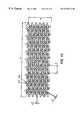
- FIGS. 5-14are flattened plan views showing stents made according to the present invention. Each of the stent patterns shown would be curved into a cylindrical shape as applied to the balloon catheter as shown in FIG. 1 .
- the medical device 1 of the present inventionincludes a catheter 2 and a stent 3 mounted on the catheter 2 in an unexpanded condition.
- the stent 3has a hollow, cylindrical body made with a plurality of rings. As shown, the stent 3 is crimped over a balloon 4 affixed to the catheter 2 near the distal end of the catheter 2 .
- the stent 3can include a variety of configurations as shown in FIGS. 2 to 14 which are shown in an open and flattened configuration as they would appear in an unexpanded and uncrimped condition.
- the balloon 4can be practically any balloon suitable for angioplasty procedures and capable of inflation to 8 atmospheres of pressure.
- a preferred type of balloon 4is a balloon with multiple folds which permits the stent to expand evenly that is approximately the same length as the stent.
- the stent 3can be held onto the balloon 4 by retention techniques that are well known to those skilled in the art.
- rings 10 a-care shown.
- Each of the rings 10 a-cextend circumferentially around the cylindrical body of the stent 3 and include an undulating series of peaks 11 and valleys 12 .
- the undulating peaks 11 and valleys 12 of the rings 10 a-care formed by opposing curved segments 13 a-b joined to each other by substantially straight segments 14 .
- the rings 10 a-care joined together in a repeating pattern by a series of links 15 which are shaped and arranged to promote longitudinal flexibility as the stent is delivered on the catheter and effective scaffolding after deployment.
- a link 15can be provided which interconnects with the rings 10 a-c at points 16 a-b on the rings 10 a-b which are substantially centered between the respective peaks 11 and valleys 12 of the rings 10 a-c and yet allows the link to nest within the peaks 11 and valleys 12 of the rings 10 a-c as the stent is crimped onto the balloon 4 of the catheter 3 .
- Thisis accomplished in part by providing at least two curved segments 17 a-b in the link in a central portion of the link 15 .
- no more than one link 15is connected to either of the points 16 a-b .
- the nesting of link 15 and ring 10 a-c componentsis also made possible by providing only three of the links 15 attaching each of the rings 10 a-c to its immediate neighbor. This leaves some of the straight segments 14 without connections and the links are spaced-apart such that no links 15 have adjacent connections to the rings 10 a-c which oppose each other.
- a radiopaque marker 18is joined to ring 10 a inside a circular land portion 19 a link 15 a joins the land portion with the adjacent ring 10 b such that the link 15 a resides between two peaks of ring 10 a such that it will not interfere with the ring as the stent 3 is crimped onto the balloon 4 of the catheter 2 .
- the rings 20 a-care provided with inflection points 21 on some portions of the rings 20 a-c which extend between an adjacent peak 22 and valley 23 of the rings 20 a-c .
- a portion of the ringextends in a generally circumferential direction (indicated generally 24 ) for a short distance.
- the inflection point 21is shown substantially centered between a peak 22 and a valley 23 of the rings 20 a-c .
- a link 25is joined at one end at the inflection point 21 a on one ring 20 a and also joined at a second end at a second inflection point 21 b on an adjacent ring 20 b .
- This link 25joins the rings 20 a-b together.
- Each link 25includes at least two curved segments 26 a-b in the unexpanded stent 3 which promote the tendency of the stent 3 to flex longitudinally when it is subjected to bending forces such as those encountered during delivery of the stent 3 and catheter 2 through a tortuous coronary artery. It can be seen in FIG. 3 that the short portion of the rings 20 a-c at the inflection point 21 which extends generally circumferentially has a length measured circumferentially which is about equal to a width of the link 25 to which it is attached.
- the undulations of the rings 20 a-cinclude generally straight segments 27 between the peaks 22 and valleys 23 , the straight segments 27 are interrupted by an inflection point 21 which produces a offset portion in the straight segment 27 in a generally circumferential direction 24 . Only one link 25 is shown to be connected to either of the inflection points 21 a-b .
- the links 25can be arranged to provide flexibility whether the peaks 22 and valleys 23 of the rings 20 a-c are arranged to make the rings 20 a-c appear to be mirror images to each other (i.e. peaks line up with or closely approach each other) or as shown here where the peaks 22 and valleys 23 are paired with each other in an in-phase relationship or any alignment of the rings intermediate to those positions.
- the rings 20 a-care joined by multiple links 25 (preferably 3 or more to provide good scaffolding) and are shown to have the same number of inflection points 21 on each ring 20 a-c as the number of attaching links 25 .
- any curves or bends in the links 25are preferably of a complimentary shape to each other such that they will nest together when the stent 3 is crimped onto the balloon 4 of the catheter 2 .
- the end ring 20 aincludes a radiopaque marker 28 which provides fluoroscopic confirmation of the position of the stent 3 when it is advanced into the patient.
- the adjacent ring portionsare provided with curved segments 29 a-b which permit them to nest with the circular form of the marker 28 as the stent 3 is crimped onto the balloon 4 of the catheter 2 .
- the rings 30 a-c of the stent 3have undulating peaks 31 and valleys 32 arranged with the undulating peaks 31 and valleys 32 of an adjacent rings 30 a-c such that the rings 30 a-c appear as mirror images of each other.
- a link 33can be provided which interconnects with the rings 30 a-c at points on the rings which are substantially centered between the respective peaks 31 and valleys 32 of the rings 30 a-c and yet allows the link 33 to nest within the peaks 31 and valleys 32 of the rings.
- a link 33which includes a sharply curved segment 34 a-b at each end and a straight or gently curved central segment provided that it is connected at a “dead end” where only one link 33 is connected at any one ring segment between a peak 31 and valley 32 .
- a link 33can also nest with the opposing ring segments as the stent 3 is crimped onto the balloon 4 of a catheter 2 .
- FIG. 4Also shown in FIG. 4 is the adjustment in the relative amplitudes of the undulations between the rings 30 a-c .
- Ring 30 ais shown to have a smaller amplitude in dimension “A” than the amplitude of ring 30 b as shown in dimension “B”.
- This variation in amplitudecan be particularly important in stent designs where the stent 3 may tend to flare at the ends as the stent is advanced through tortuous arteries since the lower amplitude ring 30 a at the end of the stent 3 will have a reduced tendency to be deformed and tip outward when the stent 3 is subjected to longitudinal bending forces.
- the lower amplitude ring 30 acan be on a distal or proximal end of the stent 3 .
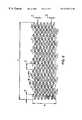
- the stent 3has a length “A” which can be about 8 to 30 mm (and as depicted could be about 15-25) mm for a coronary artery application although those skilled in the art will appreciate that the pattern can be configured to give many lengths.
- the dimension “B”refers to the circumference of the stent 3 for a coronary application which can be about 3-7 mm and gives an uncrimped diameter for the stent 3 of about 1-2 mm.
- the dimension “C”refers to the width of one of the rings which in this example could be in the range of about 0.08 to 0.12 mm.
- the dimension “D”refers to the amplitude of one of the rings and in this example could be in the range of about 0.75 to 2.5 mm.
- the dimension “E”refers to the peak-to-peak spacing for the rings and in this example could be in the range of about 1-3 mm.
- the dimension “F”refers to the width of a connecting link and in this example could be in the range of about 0.06 to 0.1 mm.
- the dimensions G and Hrefer to the diameter of the radiopaque marker and the width of the portion of the ring holding the marker.
- This stent 3can be made by laser cutting from a tube of stainless steel or other suitable material by methods which are well known by those skilled in the art. Similar structures are marked with the same dimensional symbols (“A” to “H”) in each of the drawings FIGS. 5-14 for the convenience of the reader.
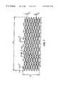
- the stent 3 of FIG. 5has been modified by the addition of more connecting links 40 and the use of shorter amplitude rings 41 (i.e. reductions in dimensions “D” and “E”) in combination with reductions in the widths in various components (i.e. reductions in dimensions “C” and “F”) in order to provide better crimp profile, flexibility and scaffolding.
- the links 40can vary somewhat in width along their length in order to modify or direct the way in which the link 40 can flex as the stent 3 is deployed through a tortuous body lumen.
- the ends of the links 40flare out just before the connection points 42 a-b in order to provide increased resistance to flexing near the connection points 42 a-b.
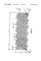
- the stent 3is made in a configuration which combines features shown in the stents 3 of FIGS. 3 and 4.
- the stent 3employs rings 50 which are arranged in a mirror image configuration. Connecting links 51 are connected to rings 50 at inflection points 52 a-b with a slightly curved connecting link 51 which provides improved flexibility.
- the connecting links 51“dead end” at the inflection points 52 a-b to also provide flexibility.
- the number of rings 50are increased and the amplitude of the rings 50 is reduced (i.e. reductions in dimensions “D”, “E”, “C” and “F”).
- the “cell” sizei.e. the size of the smallest repeating unit in the pattern) is reduced and scaffolding is improved.
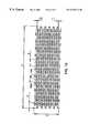
- the stent 3 of FIG. 6is modified by adding a longer and more highly curved link 60 and by adding another two bends in the undulation in each of the rings 61 .
- the resulting stent 3had improved scaffolding from smaller cell size and more flexibility from the more curved link 60 .
- Radiopaque markers 62 a-bnest with the adjacent ring elements as the stent 3 is crimped onto the balloon 4 of the catheter 2 .
- the links 60 a-b connecting the ring immediately adjacent to the radiopaque markersare shorter than the other links and are attached to the ring at a portion of the ring away from the radiopaque marker 62 a . This provides the markers 62 a-b with additional space and ring flexibility to permit improved crimping of the stent 3 onto the balloon 4 .
- the stent 3is a maximum flexibility version of the stent 3 of FIG. 8 made by making the connecting link 70 even more curved and increasing the cell size to permit the link 70 to flex in the space between the peaks 71 and valleys 72 of adjacent rings 73 .
- the stent 3is a variant of the stent 3 of FIG. 6 in which the dimension “D” is relatively smaller in relation to dimension “E” such that more space is available between the rings 80 so that the stent 3 can flex with maximum clearance between those components when the stent 3 is deployed in the bend of a body lumen.
- Radiopaque markers 82 a-bare located at opposite ends of the stent 3 to allow the physician to precisely identify the position of the ends of the stent 3 fluoroscopically while the stent 3 is being deployed into the patient.
- the markers 82 a-bcan take the form of a thin gold disk set into an portion of the pattern.
- the markers 82 a-bhave their highest fluoroscopic visibility when looking directly down onto the flat plane of the disk and lesser visibility when looking at the edge of the disk. Therefore, the markers 82 a-b can be aligned with each other so as to both be visible at the same intensity no matter what the rotational orientation of the stent (as shown in FIG. 9) or offset (shown in FIG. 10 about 90 degrees offset) with regard to each other to permit at least one marker 82 a-b to always be viewed in its highly observable flat orientation. More markers can be added to those shown in FIGS. 9-10 so that each end of the stent 3 has two or more markers in a relative offset position which then permits one of the markers at each end to always be brightly observable no matter what rotational orientation the stent 3 is in.
- the stent 3is a variant of the stent 3 of FIGS. 3 and 4 with long, relatively straight links 90 joined with rings 91 at inflection points 92 a-b . It should be noted that in the center of the pattern two links 90 are joined at each inflection point 92 a-b on opposing sides without compromising the ability of the ring 91 and link 90 elements to nest as the stent 3 is crimped onto the balloon 4 of the catheter 2 .
- the use of multiple links 90 at each inflection point 92 a-bprovides a greater number of links 90 overall and a therefore a greater amount of scaffolding in the expanded stent 3 than in other designs.
- the stent 3is a variant of the stent 3 of FIGS. 3 and 12 with curved connecting links 100 replacing the straighter links in FIG. 12 .
- the links 100are connected to the rings 101 at inflection points 102 a-b such that more than one link 100 is attached at each inflection point 102 a-b.
- the stent 3is a variant of the stent 3 of FIG. 12 in which a longer and more curved link 110 is used to improve flexibility of the stent 3 .
- the links 110include a peaked portion 111 which extends in the circumferential direction of the stent 3 . It is important to note that the links 110 have peaked portions which have the ability to conform to each other and nest as the stent 3 is crimped onto the balloon 4 of the catheter 2 .
- the stent 3is a variant of the stent 3 of FIG. 13 in which the cell size is increased slightly and the shape of the peaked portion 120 a-b of each link 121 are altered so that the adjacent peak portions 120 a-b will conform and nest better when the stent 3 is crimped. It will be noted that every peak portion 120 a-b is slightly offset from its nearest neighbor to compensate for the slight alteration in the shape of the link 121 that takes place as the stent 3 is crimped. This provides a more precise nesting of the links 121 in the crimped stent 3 . Also to be noted in connection with FIG. 14 is the relative position of the connecting links 121 , 122 with respect to the inflection point 123 a .
- the first connecting link 121is connected to the inflection point 123 a at a lower portion of the inflection point 123 a while the second connecting link 122 is connected at an opposite side of the inflection point 123 a at an upper portion of the inflection point 123 a .
- the connecting links 121 , 122are connected to adjacent rings 126 a-b such that a link 121 connects at one end to one ring 126 a at a lower portion of the inflection point 123 a and at the other end at an upper portion of the inflection point 123 b .
- each peak 124 and each valley 125has two connecting links 121 , 122 extending laterally past them to join with another ring 126 a-b .
- the connecting links 121 , 122proceed from one end attachment at an inflection point 123 a-b such that they parallel the portion of the ring 126 a-b and are positioned such that when the stent 3 is expanded they will extend outward from the inflection point 123 a-b and assist in the scaffolding provided by the central portion of the ring 126 a-b .
- the connecting links 121 , 122also extend past the peak 124 or valley 125 components to extend the scaffolding provided by the peak 124 and valley 125 components of the rings 126 a-b toward the next ring.
- connecting links 121 , 122extend upwardly past the peak 124 and valley 125 portions of the rings 126 a-b into peaked portions 120 a-b .
- This arrangementprovides highly effective scaffolding for the stent 3 when it is expanded against a body lumen of the patient.
Landscapes
- Health & Medical Sciences (AREA)
- Engineering & Computer Science (AREA)
- Biomedical Technology (AREA)
- Heart & Thoracic Surgery (AREA)
- Life Sciences & Earth Sciences (AREA)
- Cardiology (AREA)
- Oral & Maxillofacial Surgery (AREA)
- Transplantation (AREA)
- Physics & Mathematics (AREA)
- Vascular Medicine (AREA)
- Optics & Photonics (AREA)
- Animal Behavior & Ethology (AREA)
- General Health & Medical Sciences (AREA)
- Public Health (AREA)
- Veterinary Medicine (AREA)
- Media Introduction/Drainage Providing Device (AREA)
- Materials For Medical Uses (AREA)
Abstract
Description
This invention relates to intraluminal endovascular stenting, a method by which a prosthesis is inserted into a body tube and expanded so as to reopen a collapsed vessel wall and prevent the wall from recollapsing into the lumen. Endovascular stenting is particularly useful for arteries which are blocked or narrowed and is an alternative to surgical procedures that intend to bypass the occlusion.
Percutaneous transluminal coronary angioplasty (PTCA) is used to open coronary arteries which have been occluded by a build-up of cholesterol fats or atherosclerotic plaque. Typically a guidewire is steered through the vascular system to the site of therapy. A guiding catheter, for example, can then be advanced over the guidewire and a balloon catheter advanced within the guiding catheter over the guidewire. The balloon at the distal end of the catheter is inflated causing the site of the stenosis to widen. The dilatation of the occlusion, however, can form flaps, fissures and dissections which threaten re-closure of the dilated vessel or even perforations in the vessel wall. Implantation of a metal stent can provide support for such flaps and dissections and thereby prevent reclosure of the vessel or provide a patch repair for a perforated vessel wall until corrective surgery can be performed. Reducing the possibility of restenosis after angioplasty reduces the likelihood that a secondary angioplasty procedure or a surgical bypass operation will be necessary.
An implanted prosthesis such as a stent can preclude additional procedures and maintain vascular patency by mechanically supporting dilated vessels to prevent vessel collapse. Stents can also be used to repair aneurysms, to support artificial vessels as liners of vessels or to repair dissections. Stents are suited to the treatment of any body lumen, including the vas deferens, ducts of the gallbladder, prostate gland, trachea, bronchus and liver. The body lumens range in size from 1.5 mm in the coronary vessels to 30 mm in the aortic vessel.
A stent typically is a cylindrically shaped device formed from wire(s)or a tube and intended to act as a permanent prosthesis. A stent is deployed in a body lumen from a radially compressed configuration into a radially expanded configuration which allows it to contact and support a body lumen. The stent can be made to be radially self-expanding or expandable by the use of an expansion device. The self expanding stent is made from a resilient springy material while the device expandable stent is made from a material which is plastically deformable. A plastically deformable stent can be implanted during an angioplasty procedure by using a balloon catheter bearing a stent which has been crimped onto the balloon. Stents radially expand as the balloon is inflated, forcing the stent into contact with the body lumen thereby forming a supporting relationship with the vessel walls. Deployment is effected after the stent has been introduced percutaneously, transported transluminally and positioned at a desired location by means of the balloon catheter.
A balloon of appropriate size and pressure is first used to open the lesion. The process is repeated with a stent crimped on a balloon. The stent is deployed when the balloon is inflated. The stent remains as a permanent scaffold after the balloon is withdrawn. A balloon capable of withstanding relatively high inflation pressures may be preferable for stent deployment because the stent must be forced against the artery's interior wall so that it will fully expand thereby precluding the ends of the stent from hanging down into the channel encouraging the formation of thrombus.
Previous structures used as stents or intraluminal vascular grafts have included coiled stainless steel springs; helical wound spring coil made from shape memory alloy; expanding metal stents formed in a zig-zag pattern; diamond shaped, rectangular shaped, and other mesh and non-mesh designs. Exemplary stent devices are disclosed in U.S. Pat. No. 5,776,161 issued to Globerman, U.S. Pat. No. 5,449,373 issued to Pinchasik et al, U.S. Pat. No. 5,643,312 issued to Fischell et al and U.S. Pat. No. 5,421,955 issued to Lau et al.
Problems to be overcome in stent design include inadequate radial force to maintain expansion; inadequate scaffolding of tissue to the wall; pre-dilated longitudinal rigidity which negatively impacts on stent delivery; and shortening of the stent as a consequence of radial expansion. Predilation stent longitudinal rigidity is a significant shortcoming, and prevents the threading of the stent through long tortuous vessels and lesions. Shortening of the stent is also a problem, as it is important that the stent cover the entire lesion to minimize the risk of post-operative complications. Many of these problems are the result of difficult design problems resulting from the often conflicting goals of stent design. For example, it is desirable to have a high degree of scaffolding in the stent when the stent is expanded to its rated radial size so that the vessel wall will have uniform support. However, it is also desirable to have a small, relatively smooth delivered profile when the stent is mounted on the catheter to permit the stent and catheter to traverse small diameter lesions. The person skilled in the art will appreciate that as a stent with a very small delivered profile expands radially its structural elements become farther apart and create openings which reduce the amount of scaffolding available to support the vessel. A similar situation exists with respect to the conflicting goals of improved scaffolding and flexibility during catheter delivery since proper scaffolding will not be accomplished if there are few supporting structural elements and yet a stent with too many structural elements may be difficult to crimp onto the balloon catheter such that the structural elements will not abut or interfere with each other during delivery through tortuous vessels. Also, in some stents, during plastic deformation of the stent (i.e. balloon expansion) the strain is concentrated at small zones. This limits the properties of the material that can be used as well as the radial force and the expansion rate.
U.S. Pat. No. 5,776,161 issued to Globerman, which is incorporated by reference herein in its entirety, addresses a number of these issues. Globerman discloses an expandable stent having a small initial diameter, flexibility along its longitudinal axis prior to expansion and minimization of rigid local strain on the stent material by the presence of rotation joints which have minimal strain during stent expansion. The stent is substantially the same length before and after expansion and being flexible longitudinally when constrained, it is easy to deliver. However additional improvements in longitudinal flexibility in the crimped stent during delivery and scaffolding after delivery are still desired.
These and other objects are accomplished by the present invention. The medical device of the present invention includes a catheter and a stent mounted on the catheter, the stent having a hollow, cylindrical body made with a plurality of rings. The rings each extend circumferentially around the cylindrical body and include an undulating series of peaks and valleys. Typically, the undulating peaks and valleys of the rings are formed by opposing curved segments joined to each other by substantially straight segments. The rings are joined together by a series of links which are shaped and arranged to promote longitudinal flexibility as the stent is delivered on the catheter and effective scaffolding after deployment and to prevent shortening of the stent as the stent is expanded.
In one aspect of the invention, the rings are provided with inflection points on some portions of the rings which extend between an adjacent peak and valley of the ring. At each inflection point, a portion of the ring extends in a generally circumferential direction for a short distance. Typically, the inflection point is substantially centered between a peak and a valley of the ring. A link is joined at one end at the inflection point on one ring and also joined at a second end at a second inflection point on an adjacent ring. This link joins the rings together. Preferably, the link includes at least two curved segments in the unexpanded device which are capable of deflecting to promote the tendency of the stent to flex longitudinally when it is subjected to bending forces such as those encountered during delivery of the stent and catheter through a tortuous coronary artery. Also preferably, the short portion of the ring at the inflection point which extends generally circumferentially has a length measured circumferentially which is at least as great as the width of the link to which it is attached. Preferably, the circumferential length is no more than about twice the width of the link to which it is attached. This promotes the scaffolding provided to the vessel by the expanded stent since the links can be fit together closely in a nested arrangement with the undulations of the rings as the stent is crimped on the balloon catheter. By “nest”, “nested” or nesting” herein we mean that the elements are conformally arranged such they can be in very close proximity when the stent is crimped onto the catheter but without substantial contact that would affect the ability of the various elements to move in relation to each other as the stent and catheter are advanced through a tortuous body vessel. Where the undulations of the ring include generally straight segments between the peaks and valleys, the straight segments may be interrupted by an inflection point which produces a offset portion in the straight segment in a generally circumferential direction. In some preferred embodiments of the invention, no more than one link is connected to either of the first and second inflection points. This makes the inflection point a “dead end” in the longitudinal extent of the connecting links for the stent and permits some of the flexing forces which are not absorbed by the link itself to be absorbed by the rings to which it is attached. The links can be arranged to provide flexibility whether the peaks and valleys of the rings are arranged to make the rings appear to be mirror images to each other (i.e. peaks line up with or closely approach each other) or whether the peaks and valleys are paired with each other in an in-phase relationship or any alignment of the rings intermediate to those positions. Preferably, the rings are joined by multiple links (most preferably 3 or more) and have the same number of inflection points on each ring as the number of attaching links. When a large number of connecting links are employed, any curves or bends in the links are preferably of a complimentary shape to each other such that they will nest together when the stent is crimped onto the catheter.
Another aspect of the invention is the conformal nesting of ring and link components such that the stent can be readily crimped onto a balloon or other expansion device on the catheter. The stent made according to the present invention may be made from a tube which is cut with lasers or other techniques which are well known to those skilled in the art. The initial pattern cut into the tube includes link and ring components which cooperate with each other but which provide sufficient spacing between components that the stent can be crimped onto a catheter without causing general abutment of the ring and link components with each other and also permit longitudinal movement of the link components without disturbing the crimp of the ring components on the catheter during deployment of the stent through tortuous coronary arteries. The need for spacing between the components in the crimped condition must be balanced with the need to provide improved scaffolding of the vessel being treated. A relatively abundant number of links provides improved scaffolding of the vessel but potentially interferes with the ability to crimp the stent onto the catheter. In the present invention, the inflection points can provide the spacing needed for the nesting of the ring and link components by extending the ring in a generally circumferential direction for a distance which is sufficient to accommodate the width of the link component and provide space needed between the link components and the ring components which allows the stent to be crimped onto the catheter. In some embodiments of the invention, each inflection point includes an attachment to two connecting links extending in opposing directions and the circumferential offset at the inflection point provides for nesting of both connecting links with the ring components on the opposite sides. Thus, in the present invention, large numbers of connecting links can be included within a crimpable stent design.
Another aspect of the invention is to provide flexibility in the stent crimped on the catheter such that the stent can flex near the inflection points without significant radial expansion as the stent is subjected to bending along a longitudinal axis as it is advanced through bends in a coronary artery. As stents are advanced through tortuosities of a vessel, they are subjected to bending forces which can produce longitudinal stresses on the connector links. If the movement of connector links pulls the undulations open from their crimped position, the stent can become radially enlarged and have difficulty in crossing a narrow lesion. The present invention reduces the potential for this problem by aligning the connection of the links with the rings at a short, circumferentially extending portion, by providing curvature in the links which are then able to flex and thereby reduce stress on the junctions between the rings and the links and by providing “dead end” connections with the links which then avoids the transmission of forces from ring to ring throughout the length of the stent.
Yet another aspect of the invention is in connection with the stent configuration in which the undulating peaks and valleys of the rings are oriented such that the rings have peaks and valleys which are paired with each other in an in-phase relationship. In such a configuration, a link can be provided which interconnects with the rings at points on the rings which are substantially centered between the respective peaks and valleys of the rings and yet allows the link to nest within the peaks and valleys of the rings. This can be accomplished by providing at least two curved segments in the link in a central portion of the link.
Yet another aspect of the invention is in connection with the stent configuration in which the undulating peaks and valleys of the first ring are arranged with the undulating peaks and valleys of the second ring such that the first and second rings appear as mirror images of each other. In such a configuration, a link can be provided which interconnects with the rings at points on the rings which are substantially centered between the respective peaks and valleys of the rings and yet allows the link to nest within the peaks and valleys of the rings. This can be accomplished by providing a link including a sharp radius segment at each end and a gently curved central segment.
FIG. 1 is an elevational view of a balloon catheter with a stent mounted on the balloon portion of the catheter.
FIGS. 2-5 are flattened plan views showing portions of stents made according to the present invention. Each of the stent patterns shown would be curved into a cylindrical shape as applied to the balloon catheter as shown in FIG.1.
FIGS. 5-14 are flattened plan views showing stents made according to the present invention. Each of the stent patterns shown would be curved into a cylindrical shape as applied to the balloon catheter as shown in FIG.1.
Referring now to FIG. 1, the medical device1 of the present invention includes a catheter2 and astent 3 mounted on the catheter2 in an unexpanded condition. Thestent 3 has a hollow, cylindrical body made with a plurality of rings. As shown, thestent 3 is crimped over a balloon4 affixed to the catheter2 near the distal end of the catheter2. Thestent 3 can include a variety of configurations as shown in FIGS. 2 to14 which are shown in an open and flattened configuration as they would appear in an unexpanded and uncrimped condition. The balloon4 can be practically any balloon suitable for angioplasty procedures and capable of inflation to 8 atmospheres of pressure. A preferred type of balloon4 is a balloon with multiple folds which permits the stent to expand evenly that is approximately the same length as the stent. In addition to crimping, thestent 3 can be held onto the balloon4 by retention techniques that are well known to those skilled in the art.
Referring now also to FIG. 2, rings10a-care shown. Each of the rings10a-cextend circumferentially around the cylindrical body of thestent 3 and include an undulating series ofpeaks 11 andvalleys 12. The undulatingpeaks 11 andvalleys 12 of the rings10a-care formed by opposing curved segments13a-bjoined to each other by substantiallystraight segments 14. The rings10a-care joined together in a repeating pattern by a series oflinks 15 which are shaped and arranged to promote longitudinal flexibility as the stent is delivered on the catheter and effective scaffolding after deployment. In connection with thestent 3 configuration of FIG. 2, it should be noted that the configuration of undulatingpeaks 11 andvalleys 12 of the rings10a-care oriented such that the rings havepeaks 11 andvalleys 12 which are paired with each other in an in-phase relationship. In this configuration, alink 15 can be provided which interconnects with the rings10a-cat points16a-bon the rings10a-bwhich are substantially centered between therespective peaks 11 andvalleys 12 of the rings10a-cand yet allows the link to nest within thepeaks 11 andvalleys 12 of the rings10a-cas the stent is crimped onto the balloon4 of thecatheter 3. This is accomplished in part by providing at least two curved segments17a-bin the link in a central portion of thelink 15. As shown in FIG. 2, no more than onelink 15 is connected to either of the points16a-b. This makes the points16a-b“dead ends” in the longitudinal extent of the connectinglinks 15 for thestent 3 and permits some of the flexing forces which are not absorbed by thelink 15 itself at the curved segments17a-bto be absorbed by the rings10a-cto which it is attached. The nesting oflink 15 and ring10a-ccomponents is also made possible by providing only three of thelinks 15 attaching each of the rings10a-cto its immediate neighbor. This leaves some of thestraight segments 14 without connections and the links are spaced-apart such that nolinks 15 have adjacent connections to the rings10a-cwhich oppose each other. Aradiopaque marker 18 is joined to ring10ainside a circular land portion19alink 15ajoins the land portion with theadjacent ring 10bsuch that thelink 15aresides between two peaks ofring 10asuch that it will not interfere with the ring as thestent 3 is crimped onto the balloon4 of the catheter2.
Referring now to FIGS. 1 and 3, in another embodiment of the invention, the rings20a-care provided withinflection points 21 on some portions of the rings20a-cwhich extend between anadjacent peak 22 andvalley 23 of the rings20a-c. At eachinflection point 21, a portion of the ring extends in a generally circumferential direction (indicated generally24) for a short distance. Theinflection point 21 is shown substantially centered between a peak22 and avalley 23 of the rings20a-c. Alink 25 is joined at one end at theinflection point 21 a on onering 20aand also joined at a second end at asecond inflection point 21bon anadjacent ring 20b. Thislink 25 joins the rings20a-btogether. Eachlink 25 includes at least two curved segments26a-bin theunexpanded stent 3 which promote the tendency of thestent 3 to flex longitudinally when it is subjected to bending forces such as those encountered during delivery of thestent 3 and catheter2 through a tortuous coronary artery. It can be seen in FIG. 3 that the short portion of the rings20a-cat theinflection point 21 which extends generally circumferentially has a length measured circumferentially which is about equal to a width of thelink 25 to which it is attached. This promotes the scaffolding provided to the vessel by the expandedstent 3 since thelinks 25 can be fit together closely in a nested arrangement with the undulations of the rings20a-cas thestent 3 is crimped on the balloon4 of the catheter2. When as shown in FIG. 3, the undulations of the rings20a-cinclude generallystraight segments 27 between thepeaks 22 andvalleys 23, thestraight segments 27 are interrupted by aninflection point 21 which produces a offset portion in thestraight segment 27 in a generallycircumferential direction 24. Only onelink 25 is shown to be connected to either of theinflection points 21a-b. This makes theinflection point 21 a “dead end” in the longitudinal extent of the connectinglinks 25 for thestent 3 and permits some of the flexing forces which are not absorbed by thelink 25 itself to be absorbed by the rings10a-cto which it is attached. Thelinks 25 can be arranged to provide flexibility whether thepeaks 22 andvalleys 23 of the rings20a-care arranged to make the rings20a-cappear to be mirror images to each other (i.e. peaks line up with or closely approach each other) or as shown here where thepeaks 22 andvalleys 23 are paired with each other in an in-phase relationship or any alignment of the rings intermediate to those positions. The rings20a-care joined by multiple links25 (preferably 3 or more to provide good scaffolding) and are shown to have the same number ofinflection points 21 on each ring20a-cas the number of attachinglinks 25. When a large number of connectinglinks 25 are employed, any curves or bends in thelinks 25 are preferably of a complimentary shape to each other such that they will nest together when thestent 3 is crimped onto the balloon4 of the catheter2. It should also be noted in FIG. 3 that theend ring 20aincludes aradiopaque marker 28 which provides fluoroscopic confirmation of the position of thestent 3 when it is advanced into the patient. The adjacent ring portions are provided with curved segments29a-bwhich permit them to nest with the circular form of themarker 28 as thestent 3 is crimped onto the balloon4 of the catheter2.
Referring now to FIGS. 1 and 4, in yet another embodiment of the invention, the rings30a-cof thestent 3 have undulating peaks31 and valleys32 arranged with the undulating peaks31 and valleys32 of an adjacent rings30a-csuch that the rings30a-cappear as mirror images of each other. In such a configuration, alink 33 can be provided which interconnects with the rings30a-cat points on the rings which are substantially centered between the respective peaks31 and valleys32 of the rings30a-cand yet allows thelink 33 to nest within the peaks31 and valleys32 of the rings. This can be accomplished by providing alink 33 which includes a sharply curved segment34a-bat each end and a straight or gently curved central segment provided that it is connected at a “dead end” where only onelink 33 is connected at any one ring segment between a peak31 and valley32. As shown, such alink 33 can also nest with the opposing ring segments as thestent 3 is crimped onto the balloon4 of a catheter2. Also shown in FIG. 4 is the adjustment in the relative amplitudes of the undulations between the rings30a-c.Ring 30ais shown to have a smaller amplitude in dimension “A” than the amplitude ofring 30bas shown in dimension “B”. This variation in amplitude can be particularly important in stent designs where thestent 3 may tend to flare at the ends as the stent is advanced through tortuous arteries since thelower amplitude ring 30aat the end of thestent 3 will have a reduced tendency to be deformed and tip outward when thestent 3 is subjected to longitudinal bending forces. Thelower amplitude ring 30acan be on a distal or proximal end of thestent 3. The person skilled in the art will appreciate that this can be especially important in situations where one advances thestent 3 and catheter2 through a tortuous artery but, instead of deploying thestent 3, then wishes to withdraw thestent 3 into the guide catheter while it is still crimped on the balloon4. If the end of thestent 3 has become flared during the failed deployment, it can catch on the distal edge of the guide catheter as it is being withdrawn.
Referring now to FIGS. 1 and 5, a full pattern of astent 3 for a coronary artery application is shown which is substantially the same pattern which was discussed above in connection with FIG.3. Thestent 3 has a length “A” which can be about 8 to 30 mm (and as depicted could be about 15-25) mm for a coronary artery application although those skilled in the art will appreciate that the pattern can be configured to give many lengths. The dimension “B” refers to the circumference of thestent 3 for a coronary application which can be about 3-7 mm and gives an uncrimped diameter for thestent 3 of about 1-2 mm. The dimension “C” refers to the width of one of the rings which in this example could be in the range of about 0.08 to 0.12 mm. The dimension “D” refers to the amplitude of one of the rings and in this example could be in the range of about 0.75 to 2.5 mm. The dimension “E” refers to the peak-to-peak spacing for the rings and in this example could be in the range of about 1-3 mm. The dimension “F” refers to the width of a connecting link and in this example could be in the range of about 0.06 to 0.1 mm. The dimensions G and H refer to the diameter of the radiopaque marker and the width of the portion of the ring holding the marker. Thisstent 3 can be made by laser cutting from a tube of stainless steel or other suitable material by methods which are well known by those skilled in the art. Similar structures are marked with the same dimensional symbols (“A” to “H”) in each of the drawings FIGS. 5-14 for the convenience of the reader.
Referring now to FIG. 6, thestent 3 of FIG. 5 has been modified by the addition of more connectinglinks 40 and the use of shorter amplitude rings41 (i.e. reductions in dimensions “D” and “E”) in combination with reductions in the widths in various components (i.e. reductions in dimensions “C” and “F”) in order to provide better crimp profile, flexibility and scaffolding. It should be noted in connection with FIG.6 and other drawing figures that thelinks 40 can vary somewhat in width along their length in order to modify or direct the way in which thelink 40 can flex as thestent 3 is deployed through a tortuous body lumen. In this embodiment of thestent 3, the ends of thelinks 40 flare out just before the connection points42a-bin order to provide increased resistance to flexing near the connection points42a-b.
Referring now to FIG. 7, thestent 3 is made in a configuration which combines features shown in thestents 3 of FIGS. 3 and 4. Thestent 3 employsrings 50 which are arranged in a mirror image configuration.Connecting links 51 are connected torings 50 at inflection points52a-bwith a slightly curved connectinglink 51 which provides improved flexibility. The connectinglinks 51 “dead end” at the inflection points52a-bto also provide flexibility. The number ofrings 50 are increased and the amplitude of therings 50 is reduced (i.e. reductions in dimensions “D”, “E”, “C” and “F”). Thus the “cell” size ( i.e. the size of the smallest repeating unit in the pattern) is reduced and scaffolding is improved.
Referring now to FIG. 8, thestent 3 of FIG. 6 is modified by adding a longer and more highlycurved link 60 and by adding another two bends in the undulation in each of therings 61. The resultingstent 3 had improved scaffolding from smaller cell size and more flexibility from the morecurved link 60. Radiopaque markers62a-bnest with the adjacent ring elements as thestent 3 is crimped onto the balloon4 of the catheter2. In addition, thelinks 60a-bconnecting the ring immediately adjacent to the radiopaque markers are shorter than the other links and are attached to the ring at a portion of the ring away from theradiopaque marker 62a. This provides the markers62a-bwith additional space and ring flexibility to permit improved crimping of thestent 3 onto the balloon4.
Referring now to FIG. 9, thestent 3 is a maximum flexibility version of thestent 3 of FIG. 8 made by making the connectinglink 70 even more curved and increasing the cell size to permit thelink 70 to flex in the space between the peaks71 and valleys72 ofadjacent rings 73.
Referring now to FIG. 10, thestent 3 is a variant of thestent 3 of FIG. 6 in which the dimension “D” is relatively smaller in relation to dimension “E” such that more space is available between therings 80 so that thestent 3 can flex with maximum clearance between those components when thestent 3 is deployed in the bend of a body lumen. Radiopaque markers82a-bare located at opposite ends of thestent 3 to allow the physician to precisely identify the position of the ends of thestent 3 fluoroscopically while thestent 3 is being deployed into the patient. The markers82a-bcan take the form of a thin gold disk set into an portion of the pattern. The markers82a-bhave their highest fluoroscopic visibility when looking directly down onto the flat plane of the disk and lesser visibility when looking at the edge of the disk. Therefore, the markers82a-bcan be aligned with each other so as to both be visible at the same intensity no matter what the rotational orientation of the stent (as shown in FIG. 9) or offset (shown in FIG. 10 about 90 degrees offset) with regard to each other to permit at least one marker82a-bto always be viewed in its highly observable flat orientation. More markers can be added to those shown in FIGS. 9-10 so that each end of thestent 3 has two or more markers in a relative offset position which then permits one of the markers at each end to always be brightly observable no matter what rotational orientation thestent 3 is in.
Referring now to FIG. 11, thestent 3 is a variant of thestent 3 of FIGS. 3 and 4 with long, relatively straight links90 joined with rings91 at inflection points92a-b. It should be noted that in the center of the pattern two links90 are joined at each inflection point92a-bon opposing sides without compromising the ability of the ring91 and link90 elements to nest as thestent 3 is crimped onto the balloon4 of the catheter2. The use of multiple links90 at each inflection point92a-bprovides a greater number of links90 overall and a therefore a greater amount of scaffolding in the expandedstent 3 than in other designs.
Referring now to FIG. 12, thestent 3 is a variant of thestent 3 of FIGS. 3 and 12 with curved connectinglinks 100 replacing the straighter links in FIG.12. Again, thelinks 100 are connected to therings 101 at inflection points102a-bsuch that more than onelink 100 is attached at each inflection point102a-b.
Referring now to FIG. 13, thestent 3 is a variant of thestent 3 of FIG. 12 in which a longer and morecurved link 110 is used to improve flexibility of thestent 3. Thelinks 110 include apeaked portion 111 which extends in the circumferential direction of thestent 3. It is important to note that thelinks 110 have peaked portions which have the ability to conform to each other and nest as thestent 3 is crimped onto the balloon4 of the catheter2.
Referring now to FIG. 14, thestent 3 is a variant of thestent 3 of FIG. 13 in which the cell size is increased slightly and the shape of the peaked portion120a-bof eachlink 121 are altered so that the adjacent peak portions120a-bwill conform and nest better when thestent 3 is crimped. It will be noted that every peak portion120a-bis slightly offset from its nearest neighbor to compensate for the slight alteration in the shape of thelink 121 that takes place as thestent 3 is crimped. This provides a more precise nesting of thelinks 121 in thecrimped stent 3. Also to be noted in connection with FIG. 14 is the relative position of the connectinglinks inflection point 123a. The first connectinglink 121 is connected to theinflection point 123aat a lower portion of theinflection point 123awhile the second connectinglink 122 is connected at an opposite side of theinflection point 123aat an upper portion of theinflection point 123a. With the in-phase arrangement ofpeaks 124 andvalleys 125 in this pattern, the connectinglinks link 121 connects at one end to onering 126aat a lower portion of theinflection point 123aand at the other end at an upper portion of theinflection point 123b. Also to be noted in the pattern of FIG. 14 is that each peak124 and eachvalley 125 has two connectinglinks links stent 3 is expanded they will extend outward from the inflection point123a-band assist in the scaffolding provided by the central portion of the ring126a-b. The connectinglinks peak 124 orvalley 125 components to extend the scaffolding provided by thepeak 124 andvalley 125 components of the rings126a-btoward the next ring. In particular, the connectinglinks peak 124 andvalley 125 portions of the rings126a-binto peaked portions120a-b. This arrangement provides highly effective scaffolding for thestent 3 when it is expanded against a body lumen of the patient.
Those skilled in the art will further appreciate that the present invention may be embodied in other specific forms without departing from the spirit or central attributes thereof. In that the foregoing description of the present invention discloses only exemplary embodiments thereof, it is to be understood that other variations are recognized as being within the scope of the present invention. Accordingly, the present invention is not limited to the particular embodiments which have been described in detail herein.
Claims (56)
1. A medical device comprising:
a catheter and a stent mounted on the catheter, the stent comprising a hollow, cylindrical body comprised of a first ring and a second ring, the first and the second rings each extending circumferentially around the cylindrical body, the first and second rings each including an undulating series of peaks and valleys;
a first inflection point on the first ring, the first inflection point disposed on an intermediate portion of the first ring substantially centered between an adjacent peak and valley, the first inflection point including a portion extending generally circumferentially;
a second inflection point on the second ring, the second inflection point disposed on an intermediate portion of the second ring substantially centered between an adjacent peak and valley, the second inflection point including a portion extending generally circumferentially;
a link joined at a first end at the first inflection point on the first ring and at a second end at the second inflection point whereby the first and second rings are joined together.
2. A medical device as inclaim 1 wherein the link includes at least two curved segments.
3. A medical device as inclaim 1 wherein the portion of the inflection point extending generally circumferentially has a length measured circumferentially which is substantially equal to a width of the link to which it is attached.
4. A medical device as inclaim 1 wherein the stent is crimped onto a distal portion of the catheter.
5. A medical device as inclaim 4 wherein a portion of the link near its first end nests within the undulating series of peak and valleys of the first ring of the crimped stent.
6. A medical device as inclaim 4 wherein the crimped stent can flex near the first and second inflection points without significant radial expansion as the stent is subjected to bending along a longitudinal axis as it is advanced through bends in a coronary artery.
7. A medical device as inclaim 1 wherein the undulating peaks and valleys of each of the first and second rings are formed by opposing curved segments joined to each other by straight segments.
8. A medical device as inclaim 7 wherein at least one of the straight segments is interrupted by an inflection point which produces a generally circumferentially offset portion in the straight segment.
9. A medical device as inclaim 1 wherein no more than one link is connected to either of the first and second inflection points.
10. A medical device as inclaim 1 wherein the undulating peaks and valleys of the first ring are arranged with the undulating peaks and valleys of the second ring such that the first and second rings appear as mirror images of each other.
11. A medical device as inclaim 1 wherein the undulating peaks and valleys the first ring are arranged with the undulating peaks and valleys of the second ring such that the first and second rings have peaks and valleys which are paired with each other in an in-phase relationship.
12. A medical device as inclaim 1 wherein the first and second rings each include the same number of inflection points.
13. A medical device as inclaim 1 wherein the first and second rings are joined by a plurality of links.
14. A medical device as inclaim 13 wherein the plurality of links have complimentary shapes such that they will nest when the stent is crimped onto the catheter.
15. A medical device comprising:
a catheter and a stent mounted on the catheter, the stent comprising
a hollow, cylindrical body comprised of a first ring and a second ring, the first and the second rings each extending circumferentially around the cylindrical body, the first and second rings each including an undulating series of peaks and valleys;
a first inflection point on the first ring, the first inflection point disposed on an intermediate portion of the first ring substantially centered between an adjacent peak and valley;
a second inflection point on the second ring, the second inflection point disposed on an intermediate portion of the second ring substantially centered between an adjacent peak and valley;
a link joined at a first end at the first inflection point on the first ring and at a second end at the second inflection point whereby the first and second rings are joined together;
the stent crimped on the catheter such that the link nests near the first end within the undulating series of peaks and valleys of the first ring and also nests near the second end within the undulating series of peaks and valleys of the second ring.
16. A medical device as inclaim 15 wherein the link includes at least two curved segments.
17. A medical device as inclaim 15 wherein the inflection point has a length measured circumferentially which is substantially equal to a width of the link to which it is attached.
18. A medical device as inclaim 15 wherein the crimped stent can flex near the first and second inflection points without significant radial expansion as the stent is subjected to bending along a longitudinal axis as it is advanced through bends in a coronary artery.
19. A medical device as inclaim 15 wherein the undulating peaks and valleys of each of the first and second rings are formed by opposing curved segments joined to each other by straight segments.
20. A medical device as inclaim 19 wherein at least one of the straight segments is interrupted by an inflection point which produces a generally circumferentially offset portion in the straight segment.
21. A medical device as inclaim 15 wherein no more than one link is connected to either of the first and second inflection points.
22. A medical device as inclaim 15 wherein the undulating peaks and valleys of the first ring are arranged with the undulating peaks and valleys of the second ring such that the first and second rings appear as mirror images of each other.
23. A medical device as inclaim 15 wherein the undulating peaks and valleys of the first ring are arranged with the undulating peaks and valleys of the second ring such that the first and second rings have peaks and valleys which are paired with each other in an in-phase relationship.
24. A medical device as inclaim 15 wherein the first and second rings each include the same number of inflection points.
25. A medical device as inclaim 15 wherein the first and second rings are joined by a plurality of links.
26. A medical device as inclaim 25 wherein the plurality of links have complimentary shapes such that they will nest when the stent is crimped onto the catheter.
27. A medical device comprising:
a catheter and a stent mounted on the catheter, the stent composing
a hollow, cylindrical body comprised of a first ring and a second ring, the first and the second rings each extending circumferentially around the cylindrical body, the first and second rings each including an undulating series of peaks and valleys;
a first inflection point on the first ring, the first inflection point disposed on a portion of the first ring substantially centered between an adjacent peak and valley;
a second inflection point on the second ring, the second inflection point disposed on a portion of the second ring substantially centered between an adjacent peak and valley;
a link joined at a first end at the first inflection point on the first ring and at a second end at the second inflection point whereby the first and second rings are joined together;
the stent crimped on the catheter such that the stent can flex near the first and second inflection points without significant radial expansion as the stent is subjected to bending along a longitudinal axis as it is advanced through bends in a coronary artery.
28. A medical device as inclaim 27 wherein the link includes at least two curved segments.
29. A medical device as inclaim 27 wherein the inflection point has a length measured circumferentially which is substantially equal to a width of the link to which it is attached.
30. A medical device as inclaim 27 wherein the undulating peaks and valleys of each of the first and second rings are formed by opposing curved segments joined to each other by straight segments.
31. A medical device as inclaim 30 wherein at least one of the straight segments is interrupted by an inflection point which produces a generally circumferentially offset portion in the straight segment.
32. A medical device as inclaim 27 wherein no more than one link is connected to either of the first and second inflection points.
33. A medical device as inclaim 27 wherein the undulating peaks and valleys of the first ring are arranged with the undulating peaks and valleys of the second ring such that the first and second rings appear as mirror images of each other.
34. A medical device as inclaim 27 wherein the undulating peaks and valleys of the first ring are arranged with the undulating peaks and valleys of the second ring such that the first and second rings have peaks and valleys which are paired with each other in an in-phase relationship.
35. A medical device as inclaim 27 wherein the first and second rings each include the same number of inflection points.
36. A medical device as inclaim 27 wherein the first and second rings are joined by a plurality of links.
37. A medical device as inclaim 36 wherein the plurality of links have complimentary shapes such that they will nest when the stent is crimped onto the catheter.
38. A medical device comprising:
a catheter and a stent mounted on the catheter, the stent comprising
a hollow, cylindrical body comprised of at least one ring, the ring extending circumferentially around the cylindrical body, the ring including an undulating series of peaks and valleys;
an inflection point on the ring, the inflection point disposed on an intermediate portion of the ring substantially centered between an adjacent peak and valley;
a first link joined at an end at the inflection point.
39. A medical device as inclaim 38 wherein the inflection point includes a short portion extending generally circumferentially.
40. A medical device as inclaim 39 wherein the short portion of the inflection point extending generally circumferentially has a length measured circumferentially which is substantially equal to a width of the link.
41. A medical device as inclaim 38 wherein the link extends substantially parallel to a portion of the ring.
42. A medical device as inclaim 38 wherein the link extends beyond a peak or valley of the ring.
43. A medical device as inclaim 38 also comprising a second link joined at an end at the inflection point and extending from the inflection point in a direction substantially opposite to the first link.
44. A medical device as inclaim 43 wherein the first link is joined at an upper portion of the inflection point and the second link is joined at a lower portion of the inflection point.
45. A medical device as inclaim 43 wherein the first link is joined to the ring above the ring and the second link is joined to the ring below the ring.
46. A medical device as inclaim 38 wherein the stent is crimped onto a distal portion of the catheter.
47. A medical device as inclaim 46 wherein a portion of the link nests within the undulating series of peaks and valleys of the ring of the crimped stent.
48. A medical device as inclaim 46 wherein the crimped stent can flex near the inflection point without significant radial expansion as the stent is subjected to bending along a longitudinal axis as it is advanced through bends in a coronary artery.
49. A medical device as inclaim 38 wherein the undulating peaks and valleys of the ring are formed by opposing curved segments joined to each other by straight segments.
50. A medical device as inclaim 49 wherein the inflection point forms an offset at at least one of the straight segments to produce a generally circumferentially offset portion in the straight segment.
51. A medical device as inclaim 38 wherein the ring includes a plurality of inflection points and a plurality of links joined to the inflection points.
52. A medical device as inclaim 51 wherein each peak and valley has an inflection point therebetween and a first link joined at each inflection point.
53. A medical device as inclaim 52 wherein each inflection point has a second link joined at each inflection point and extending longitudinally opposite the first link.
54. A medical device as inclaim 52 wherein the plurality of links have complimentary shapes such that they will nest when the stent is crimped onto the catheter.
55. A medical device as inclaim 38 wherein the link varies in width.
56. A medical device as inclaim 55 wherein the link is wider at the end attached to the inflection point.
Priority Applications (9)
| Application Number | Priority Date | Filing Date | Title |
|---|---|---|---|
| US09/292,991US6730116B1 (en) | 1999-04-16 | 1999-04-16 | Medical device for intraluminal endovascular stenting |
| EP00906944AEP1100408B1 (en) | 1999-04-16 | 2000-01-18 | Medical device for intraluminal endovascular stenting |
| PCT/US2000/001175WO2000062710A1 (en) | 1999-04-16 | 2000-01-18 | Medical device for intraluminal endovascular stenting |
| JP2000611848AJP3568899B2 (en) | 1999-04-16 | 2000-01-18 | Medical device for intraluminal intravascular stent |
| EP07016378AEP1891910A3 (en) | 1999-04-16 | 2000-01-18 | Medical device for intraluminal endovascular stenting |
| DE60037094TDE60037094T2 (en) | 1999-04-16 | 2000-01-18 | MEDICAL DEVICE FOR INTRALUMINAL ENDOVASCULAR STENT |
| IE20000078AIES20000078A2 (en) | 1999-04-16 | 2000-01-31 | Medical device for intraluminal endovasular stenting |
| IE20010388AIES20010388A2 (en) | 1999-04-16 | 2001-04-20 | Medical device for intraluminal endovascular stenting |
| US10/377,392US6918928B2 (en) | 1999-04-16 | 2003-02-28 | Medical device for intraluminal endovascular stenting |
Applications Claiming Priority (1)
| Application Number | Priority Date | Filing Date | Title |
|---|---|---|---|
| US09/292,991US6730116B1 (en) | 1999-04-16 | 1999-04-16 | Medical device for intraluminal endovascular stenting |
Related Child Applications (1)
| Application Number | Title | Priority Date | Filing Date |
|---|---|---|---|
| US10/377,392DivisionUS6918928B2 (en) | 1999-04-16 | 2003-02-28 | Medical device for intraluminal endovascular stenting |
Publications (1)
| Publication Number | Publication Date |
|---|---|
| US6730116B1true US6730116B1 (en) | 2004-05-04 |
Family
ID=23127143
Family Applications (2)
| Application Number | Title | Priority Date | Filing Date |
|---|---|---|---|
| US09/292,991Expired - LifetimeUS6730116B1 (en) | 1999-04-16 | 1999-04-16 | Medical device for intraluminal endovascular stenting |
| US10/377,392Expired - LifetimeUS6918928B2 (en) | 1999-04-16 | 2003-02-28 | Medical device for intraluminal endovascular stenting |
Family Applications After (1)
| Application Number | Title | Priority Date | Filing Date |
|---|---|---|---|
| US10/377,392Expired - LifetimeUS6918928B2 (en) | 1999-04-16 | 2003-02-28 | Medical device for intraluminal endovascular stenting |
Country Status (6)
| Country | Link |
|---|---|
| US (2) | US6730116B1 (en) |
| EP (2) | EP1891910A3 (en) |
| JP (1) | JP3568899B2 (en) |
| DE (1) | DE60037094T2 (en) |
| IE (2) | IES20000078A2 (en) |
| WO (1) | WO2000062710A1 (en) |
Cited By (141)
| Publication number | Priority date | Publication date | Assignee | Title |
|---|---|---|---|---|
| US20020082680A1 (en)* | 2000-10-16 | 2002-06-27 | Shanley John F. | Expandable medical device for delivery of beneficial agent |
| US20030199970A1 (en)* | 1998-03-30 | 2003-10-23 | Conor Medsystems, Inc. | Expandable medical device for delivery of beneficial agent |
| US20030225448A1 (en)* | 2002-05-28 | 2003-12-04 | Scimed Life Systems, Inc. | Polar radiopaque marker for stent |
| US20040006380A1 (en)* | 2002-07-05 | 2004-01-08 | Buck Jerrick C. | Stent delivery system |
| US20040116996A1 (en)* | 2001-04-18 | 2004-06-17 | Lutz Freitag | Removable essentially cylindrical implants |
| US20040133265A1 (en)* | 2001-09-12 | 2004-07-08 | Niall Duffy | Medical device for intraluminal endovascular stenting |
| US20040142014A1 (en)* | 2002-11-08 | 2004-07-22 | Conor Medsystems, Inc. | Method and apparatus for reducing tissue damage after ischemic injury |
| US20040143322A1 (en)* | 2002-11-08 | 2004-07-22 | Conor Medsystems, Inc. | Method and apparatus for treating vulnerable artherosclerotic plaque |
| US20040186554A1 (en)* | 2003-03-19 | 2004-09-23 | Advanced Bio Prosthetic Surfaces, Ltd. | Endoluminal stent having mid-strut interconnecting members |
| US20040204756A1 (en)* | 2004-02-11 | 2004-10-14 | Diaz Stephen Hunter | Absorbent article with improved liquid acquisition capacity |
| US20040220660A1 (en)* | 2001-02-05 | 2004-11-04 | Shanley John F. | Bioresorbable stent with beneficial agent reservoirs |
| US20040225350A1 (en)* | 1998-03-30 | 2004-11-11 | Shanley John F. | Expandable medical device for delivery of beneficial agent |
| US20040238978A1 (en)* | 2002-09-20 | 2004-12-02 | Diaz Stephen Hunter | Method and apparatus for loading a benefical agent into an expandable medical device |
| US20040249449A1 (en)* | 2003-06-05 | 2004-12-09 | Conor Medsystems, Inc. | Drug delivery device and method for bi-directional drug delivery |
| US20040249443A1 (en)* | 2001-08-20 | 2004-12-09 | Shanley John F. | Expandable medical device for treating cardiac arrhythmias |
| US20040254635A1 (en)* | 1998-03-30 | 2004-12-16 | Shanley John F. | Expandable medical device for delivery of beneficial agent |
| US20050010170A1 (en)* | 2004-02-11 | 2005-01-13 | Shanley John F | Implantable medical device with beneficial agent concentration gradient |
| US20050182390A1 (en)* | 2004-02-13 | 2005-08-18 | Conor Medsystems, Inc. | Implantable drug delivery device including wire filaments |
| US20050187610A1 (en)* | 1999-10-13 | 2005-08-25 | Endosystems Llc | Non-foreshortening intraluminal prosthesis |
| US20050222676A1 (en)* | 2003-09-22 | 2005-10-06 | Shanley John F | Method and apparatus for loading a beneficial agent into an expandable medical device |
| US20050234544A1 (en)* | 2002-09-20 | 2005-10-20 | Conor Medsystems, Inc. | Expandable medical device with openings for delivery of multiple beneficial agents |
| US20050287287A1 (en)* | 2004-06-24 | 2005-12-29 | Parker Theodore L | Methods and systems for loading an implantable medical device with beneficial agent |
| USD516723S1 (en) | 2004-07-06 | 2006-03-07 | Conor Medsystems, Inc. | Stent wall structure |
| US20060064158A1 (en)* | 2004-09-01 | 2006-03-23 | Pst, Llc | Stent and method for manufacturing the stent |
| US20060064155A1 (en)* | 2004-09-01 | 2006-03-23 | Pst, Llc | Stent and method for manufacturing the stent |
| US7056338B2 (en) | 2003-03-28 | 2006-06-06 | Conor Medsystems, Inc. | Therapeutic agent delivery device with controlled therapeutic agent release rates |
| US20060122697A1 (en)* | 2002-09-20 | 2006-06-08 | Conor Medsystems, Inc. | Expandable medical device with openings for delivery of multiple beneficial agents |
| US20060149356A1 (en)* | 1998-07-08 | 2006-07-06 | Boston Scientific Scimed, Inc. | Stent |
| US20060217799A1 (en)* | 2005-03-23 | 2006-09-28 | Admedes Schuessler Gmbh | Stent |
| US20060259129A1 (en)* | 2005-04-27 | 2006-11-16 | Admedes Schuessler Gmbh | Mechanical locking of an X-ray marker in the eyelet of a stent or in another bodily implant |
| US20070043429A1 (en)* | 2005-08-18 | 2007-02-22 | Admedes Schuessler Gmbh | X-ray visibility and corrosion resistance of niti stents using markers made of sandwich material |
| US7208011B2 (en) | 2001-08-20 | 2007-04-24 | Conor Medsystems, Inc. | Implantable medical device with drug filled holes |
| US20070100434A1 (en)* | 2005-10-31 | 2007-05-03 | Boston Scientific Scimed, Inc. | Stent configurations |
| US20070150048A1 (en)* | 2005-12-23 | 2007-06-28 | Boston Scientific Scimed, Inc. | Stent |
| US20070162110A1 (en)* | 2006-01-06 | 2007-07-12 | Vipul Bhupendra Dave | Bioabsorbable drug delivery devices |
| US20070158880A1 (en)* | 2006-01-06 | 2007-07-12 | Vipul Bhupendra Dave | Methods of making bioabsorbable drug delivery devices comprised of solvent cast tubes |
| US20070160672A1 (en)* | 2006-01-06 | 2007-07-12 | Vipul Bhupendra Dave | Methods of making bioabsorbable drug delivery devices comprised of solvent cast films |
| US20070233270A1 (en)* | 2006-03-29 | 2007-10-04 | Boston Scientific Scimed, Inc. | Stent with overlap and high expansion |
| US20070233231A1 (en)* | 2006-03-30 | 2007-10-04 | Medtronic Vascular, Inc. | Customized Alloys for Stents |
| US20070239257A1 (en)* | 2006-03-29 | 2007-10-11 | Jan Weber | Stent with overlap and high extension |
| US20070250158A1 (en)* | 2006-04-25 | 2007-10-25 | Medtronic Vascular, Inc. | Laminated Implantable Medical Device Having a Metallic Coating |
| US20070259017A1 (en)* | 2006-05-05 | 2007-11-08 | Medtronic Vascular, Inc. | Medical Device Having Coating With Zeolite Drug Reservoirs |
| US20070283969A1 (en)* | 2006-06-12 | 2007-12-13 | Medtronic Vascular, Inc. | Method of Diagnosing and Treating Erectile Dysfunction |
| US20080046068A1 (en)* | 2006-05-12 | 2008-02-21 | Robert Burgermeister | Balloon expandable bioabsorbable drug eluting flexible stent |
| US20080051875A1 (en)* | 2006-07-20 | 2008-02-28 | Orbusneich Medical, Inc. | Bioabsorbable Polymeric Medical Device |
| US20080065193A1 (en)* | 2006-09-08 | 2008-03-13 | Boston Scientific Scimed, Inc. | Stent |
| US20080097575A1 (en)* | 2006-10-20 | 2008-04-24 | Orbusneich Medical, Inc. | Bioabsorbable Medical Device with Coating |
| US20080118546A1 (en)* | 2006-07-20 | 2008-05-22 | Orbusneich Medical, Inc. | Bioabsorbable polymeric composition for a medical device |
| US20080119927A1 (en)* | 2006-11-17 | 2008-05-22 | Medtronic Vascular, Inc. | Stent Coating Including Therapeutic Biodegradable Glass, and Method of Making |
| US20080132998A1 (en)* | 2004-09-29 | 2008-06-05 | Alveolus, Inc. | Active stent |
| US20080133000A1 (en)* | 2006-12-01 | 2008-06-05 | Medtronic Vascular, Inc. | Bifurcated Stent With Variable Length Branches |
| WO2008076582A2 (en) | 2006-12-15 | 2008-06-26 | Medtronic Vascular Inc. | Bioresorbable stent |
| US20080206440A1 (en)* | 2006-10-20 | 2008-08-28 | Orbusneich Medical, Inc. | Bioabsorbable Polymeric Composition and Medical Device Background |
| US20080208352A1 (en)* | 2007-02-27 | 2008-08-28 | Medtronic Vascular, Inc. | Stent Having Controlled Porosity for Improved Ductility |
| US20080206441A1 (en)* | 2007-02-27 | 2008-08-28 | Medtronic Vascular, Inc. | Ion Beam Etching a Surface of an Implantable Medical Device |
| US20080234800A1 (en)* | 2007-03-20 | 2008-09-25 | Medtronic Vascular, Inc. | Stent Including a Toggle Lock |
| US20080249609A1 (en)* | 1998-03-30 | 2008-10-09 | Shanley John F | Expandable medical device with ductile hinges |
| US20080249458A1 (en)* | 2007-04-09 | 2008-10-09 | Medtronic Vascular, Inc. | Intraventricular Shunt and Methods of Use Therefor |
| WO2008011614A3 (en)* | 2006-07-20 | 2008-10-30 | Orbusneich Medical Inc | Bioabsorbable polymeric medical device |
| US20090024207A1 (en)* | 1997-06-13 | 2009-01-22 | Addonizio Scott J | Stent Having Helical Elements |
| US7527644B2 (en) | 2002-11-05 | 2009-05-05 | Alveolus Inc. | Stent with geometry determinated functionality and method of making the same |
| US7547321B2 (en) | 2001-07-26 | 2009-06-16 | Alveolus Inc. | Removable stent and method of using the same |
| US20090163989A1 (en)* | 2007-12-19 | 2009-06-25 | Contiliano Joseph H | Balloon expandable bioabsorbable stent with a single stress concentration region interconnecting adjacent struts |
| US20090248034A1 (en)* | 2008-03-28 | 2009-10-01 | Medtronic Vascular, Inc. | Method of Diagnosing and Treating Benign Prostatic Hyperplasia |
| US7604660B2 (en) | 2003-05-01 | 2009-10-20 | Merit Medical Systems, Inc. | Bifurcated medical appliance delivery apparatus and method |
| US20090264986A1 (en)* | 2002-08-30 | 2009-10-22 | C.R. Bard, Inc. | Helical stent having improved flexibility and expandability |
| US7608099B2 (en) | 2002-10-26 | 2009-10-27 | Merit Medical Systems Inc. | Medical appliance delivery apparatus and method of use |
| US7637934B2 (en) | 2003-03-31 | 2009-12-29 | Merit Medical Systems, Inc. | Medical appliance optical delivery and deployment apparatus and method |
| US7637942B2 (en) | 2002-11-05 | 2009-12-29 | Merit Medical Systems, Inc. | Coated stent with geometry determinated functionality and method of making the same |
| US20100021620A1 (en)* | 2008-07-25 | 2010-01-28 | Medtronic Vascular, Inc. | Low Temperature Drug Deposition |
| US20100036471A1 (en)* | 2008-08-05 | 2010-02-11 | Medtronic Vascular, Inc. | Method of Diagnosing and Treating Lower Urinary Tract Symptoms |
| US20100093946A1 (en)* | 2008-10-11 | 2010-04-15 | Orbusneich Medical, Inc. | Bioabsorbable Polymeric Compositions and Medical Devices |
| US20100094405A1 (en)* | 2008-10-10 | 2010-04-15 | Orbusneich Medical, Inc. | Bioabsorbable Polymeric Medical Device |
| US20100114297A1 (en)* | 2001-09-18 | 2010-05-06 | Abbott Laboratories Vascular Enterprises Limited | Stent |
| US7731654B2 (en) | 2005-05-13 | 2010-06-08 | Merit Medical Systems, Inc. | Delivery device with viewing window and associated method |
| US20100152836A1 (en)* | 2000-03-06 | 2010-06-17 | Boston Scientific Scimed, Inc. | Intraluminar perforated radially expandable drug delivery prosthesis and a method for the production thereof |
| US20100204770A1 (en)* | 2009-02-10 | 2010-08-12 | Medtronic Vascular, Inc. | Stent Delivery System Permitting in Vivo Stent Repositioning |
| US20100234940A1 (en)* | 2009-03-12 | 2010-09-16 | Medtronic Vascular , Inc. | Prosthetic Valve Delivery System |
| US20100241218A1 (en)* | 2009-03-23 | 2010-09-23 | Medtronic Vascular, Inc. | Branch Vessel Prosthesis With a Roll-Up Sealing Assembly |
| US20100256749A1 (en)* | 2009-04-06 | 2010-10-07 | Medtronic Vascular, Inc. | Packaging Systems for Percutaneously Deliverable Bioprosthetic Valves |
| US20100256723A1 (en)* | 2009-04-03 | 2010-10-07 | Medtronic Vascular, Inc. | Prosthetic Valve With Device for Restricting Expansion |
| US20100261737A1 (en)* | 2009-04-10 | 2010-10-14 | Medtronic Vascular, Inc. | Method of Treating Erectile Dysfunction |
| WO2010120546A1 (en) | 2009-04-17 | 2010-10-21 | Medtronic Vascular, Inc. | Endovascular implant having an integral graft component and method of manufacture |
| US20100286758A1 (en)* | 2009-05-05 | 2010-11-11 | Medtronic Vascular, Inc. | Implantable Temporary Flow Restrictor Device |
| US7842083B2 (en) | 2001-08-20 | 2010-11-30 | Innovational Holdings, Llc. | Expandable medical device with improved spatial distribution |
| US20100324663A1 (en)* | 2007-02-09 | 2010-12-23 | Hiroyuki Asano | Stent |
| US20110004237A1 (en)* | 2007-12-12 | 2011-01-06 | Peter Schneider | Minimal surface area contact device for holding plaque to blood vessel wall |
| US7875068B2 (en) | 2002-11-05 | 2011-01-25 | Merit Medical Systems, Inc. | Removable biliary stent |
| US20110071616A1 (en)* | 2009-09-24 | 2011-03-24 | Medtronic Vascular, Inc. | Stent Including a Toggle Lock Strut |
| US20110093059A1 (en)* | 2009-10-20 | 2011-04-21 | Svelte Medical Systems, Inc. | Hybrid stent with helical connectors |
| US20110098799A1 (en)* | 2009-10-27 | 2011-04-28 | Medtronic Vascular, Inc. | Stent Combined with a Biological Scaffold Seeded With Endothelial Cells |
| US20110130822A1 (en)* | 2007-07-20 | 2011-06-02 | Orbusneich Medical, Inc. | Bioabsorbable Polymeric Compositions and Medical Devices |
| US7959671B2 (en) | 2002-11-05 | 2011-06-14 | Merit Medical Systems, Inc. | Differential covering and coating methods |
| US20110166641A1 (en)* | 2007-02-12 | 2011-07-07 | C.R. Bard Inc. | Highly flexible stent and method of manufacture |
| US7988720B2 (en) | 2006-09-12 | 2011-08-02 | Boston Scientific Scimed, Inc. | Longitudinally flexible expandable stent |
| US20120029622A1 (en)* | 2010-08-02 | 2012-02-02 | Baillargeon Brian P | Flexible helical stent having different helical regions |
| US20120172972A1 (en)* | 2010-12-30 | 2012-07-05 | Boston Scientific Scimed, Inc. | Multi Stage Opening Stent Designs |
| WO2012149205A1 (en) | 2011-04-27 | 2012-11-01 | Dolan Mark J | Nerve impingement systems including an intravascular prosthesis and an extravascular prosthesis and associated systems and methods |
| US8333799B2 (en) | 2007-02-12 | 2012-12-18 | C. R. Bard, Inc. | Highly flexible stent and method of manufacture |
| US8449901B2 (en) | 2003-03-28 | 2013-05-28 | Innovational Holdings, Llc | Implantable medical device with beneficial agent concentration gradient |
| US8449597B2 (en) | 1995-03-01 | 2013-05-28 | Boston Scientific Scimed, Inc. | Longitudinally flexible expandable stent |
| US8790388B2 (en) | 2011-03-03 | 2014-07-29 | Boston Scientific Scimed, Inc. | Stent with reduced profile |
| US8888841B2 (en) | 2010-06-21 | 2014-11-18 | Zorion Medical, Inc. | Bioabsorbable implants |
| WO2014144683A3 (en)* | 2013-03-15 | 2015-01-29 | Atrium Medical Corporation | Stent device having reduced foreshortening and recoil and method of making same |
| USD723165S1 (en) | 2013-03-12 | 2015-02-24 | C. R. Bard, Inc. | Stent |
| US8974514B2 (en) | 2007-03-13 | 2015-03-10 | Abbott Cardiovascular Systems Inc. | Intravascular stent with integrated link and ring strut |
| US8986369B2 (en) | 2010-12-01 | 2015-03-24 | Zorion Medical, Inc. | Magnesium-based absorbable implants |
| AU2011285808B2 (en)* | 2010-08-02 | 2015-04-30 | Cardinal Health 529, Llc | Flexible helical stent having intermediated non-helical region |
| US9066825B2 (en) | 2012-05-14 | 2015-06-30 | C.R. Bard, Inc. | Uniformly expandable stent |
| US20160081735A1 (en)* | 2011-05-12 | 2016-03-24 | Cvdevices, Llc | Systems and methods for cryoablation of a tissue |
| US9320627B2 (en) | 2007-05-23 | 2016-04-26 | Abbott Laboratories Vascular Enterprises Limited | Flexible stent with torque-absorbing connectors |
| US9375327B2 (en) | 2007-12-12 | 2016-06-28 | Intact Vascular, Inc. | Endovascular implant |
| US9456911B2 (en) | 2006-02-14 | 2016-10-04 | Angiomed Gmbh & Co. Medizintechnik | Highly flexible stent and method of manufacture |
| US9517146B2 (en) | 1998-09-05 | 2016-12-13 | Abbott Laboratories Vascular Enterprises Limited | Methods and apparatus for stenting comprising enhanced embolic protection coupled with improved protections against restenosis and thrombus formation |
| US9545322B2 (en) | 2007-12-12 | 2017-01-17 | Intact Vascular, Inc. | Device and method for tacking plaque to blood vessel wall |
| US9603730B2 (en) | 2007-12-12 | 2017-03-28 | Intact Vascular, Inc. | Endoluminal device and method |
| US9730818B2 (en) | 2007-12-12 | 2017-08-15 | Intact Vascular, Inc. | Endoluminal device and method |
| US10022250B2 (en) | 2007-12-12 | 2018-07-17 | Intact Vascular, Inc. | Deployment device for placement of multiple intraluminal surgical staples |
| US10085859B2 (en) | 2013-07-03 | 2018-10-02 | Medtronic Vascular, Inc. | Methods of manufacturing a drug-eluting stent |
| US10166127B2 (en) | 2007-12-12 | 2019-01-01 | Intact Vascular, Inc. | Endoluminal device and method |
| US20190060052A1 (en)* | 2017-08-23 | 2019-02-28 | Vesper Medical, Inc. | Non-Foreshortening Stent |
| US10238513B2 (en) | 2017-07-19 | 2019-03-26 | Abbott Cardiovascular Systems Inc. | Intravascular stent |
| US10245167B2 (en) | 2015-01-29 | 2019-04-02 | Intact Vascular, Inc. | Delivery device and method of delivery |
| US10271977B2 (en) | 2017-09-08 | 2019-04-30 | Vesper Medical, Inc. | Hybrid stent |
| US10271973B2 (en) | 2011-06-03 | 2019-04-30 | Intact Vascular, Inc. | Endovascular implant |
| US10433987B2 (en) | 2002-08-30 | 2019-10-08 | C. R. Bard, Inc. | Highly flexible stent and method of manufacture |
| US10500078B2 (en) | 2018-03-09 | 2019-12-10 | Vesper Medical, Inc. | Implantable stent |
| WO2020076833A1 (en)* | 2018-10-09 | 2020-04-16 | Limflow Gmbh | Devices and methods for catheter alignment |
| US10702405B2 (en) | 2016-03-31 | 2020-07-07 | Vesper Medical, Inc. | Intravascular implants |
| US10835367B2 (en) | 2013-03-08 | 2020-11-17 | Limflow Gmbh | Devices for fluid flow through body passages |
| US10898356B2 (en) | 2015-01-29 | 2021-01-26 | Intact Vascular, Inc. | Delivery device and method of delivery |
| US10993824B2 (en) | 2016-01-01 | 2021-05-04 | Intact Vascular, Inc. | Delivery device and method of delivery |
| US11241304B2 (en) | 2006-04-20 | 2022-02-08 | Limflow Gmbh | Method for fluid flow through body passages |
| US11357650B2 (en) | 2019-02-28 | 2022-06-14 | Vesper Medical, Inc. | Hybrid stent |
| US11364134B2 (en) | 2018-02-15 | 2022-06-21 | Vesper Medical, Inc. | Tapering stent |
| US11446170B2 (en) | 2004-09-08 | 2022-09-20 | Limflow Gmbh | Minimally invasive surgical apparatus and methods |
| US11471262B2 (en) | 2013-03-08 | 2022-10-18 | Limflow Gmbh | Methods for targeting a body passage to effect fluid flow |
| US11612397B2 (en) | 2019-11-01 | 2023-03-28 | Limflow Gmbh | Devices and methods for increasing blood perfusion to a distal extremity |
| US11628076B2 (en) | 2017-09-08 | 2023-04-18 | Vesper Medical, Inc. | Hybrid stent |
| US11660218B2 (en) | 2017-07-26 | 2023-05-30 | Intact Vascular, Inc. | Delivery device and method of delivery |
| US11826504B2 (en) | 2017-04-10 | 2023-11-28 | Limflow Gmbh | Methods for routing a guidewire from a first vessel and through a second vessel in lower extremity vasculature |
Families Citing this family (95)
| Publication number | Priority date | Publication date | Assignee | Title |
|---|---|---|---|---|
| US20040106985A1 (en) | 1996-04-26 | 2004-06-03 | Jang G. David | Intravascular stent |
| US6241760B1 (en) | 1996-04-26 | 2001-06-05 | G. David Jang | Intravascular stent |
| US6235053B1 (en) | 1998-02-02 | 2001-05-22 | G. David Jang | Tubular stent consists of chevron-shape expansion struts and contralaterally attached diagonal connectors |
| JP4636634B2 (en) | 1996-04-26 | 2011-02-23 | ボストン サイエンティフィック サイムド,インコーポレイテッド | Intravascular stent |
| US6190403B1 (en) | 1998-11-13 | 2001-02-20 | Cordis Corporation | Low profile radiopaque stent with increased longitudinal flexibility and radial rigidity |
| DE10044043A1 (en)* | 2000-08-30 | 2002-03-14 | Biotronik Mess & Therapieg | Repositionable stent |
| US7766956B2 (en) | 2000-09-22 | 2010-08-03 | Boston Scientific Scimed, Inc. | Intravascular stent and assembly |
| EP1309293B1 (en)* | 2000-09-22 | 2006-08-23 | Boston Scientific Scimed, Inc. | Intravascular stent apparatus |
| DE60136868D1 (en)* | 2000-09-23 | 2009-01-15 | Boston Scient Scimed Inc | Intravascular stent |
| US6485508B1 (en) | 2000-10-13 | 2002-11-26 | Mcguinness Colm P. | Low profile stent |
| US6929660B1 (en) | 2000-12-22 | 2005-08-16 | Advanced Cardiovascular Systems, Inc. | Intravascular stent |
| JP4768172B2 (en)* | 2001-09-19 | 2011-09-07 | 株式会社カネカ | Stent |
| CA2436642A1 (en)* | 2001-02-01 | 2002-08-08 | Kaneka Corporation | Stent |
| US6740114B2 (en) | 2001-03-01 | 2004-05-25 | Cordis Corporation | Flexible stent |
| US6998060B2 (en) | 2001-03-01 | 2006-02-14 | Cordis Corporation | Flexible stent and method of manufacture |
| US6790227B2 (en) | 2001-03-01 | 2004-09-14 | Cordis Corporation | Flexible stent |
| AU784552B2 (en)* | 2001-03-02 | 2006-05-04 | Cardinal Health 529, Llc | Flexible stent |
| US6629994B2 (en) | 2001-06-11 | 2003-10-07 | Advanced Cardiovascular Systems, Inc. | Intravascular stent |
| GB0121980D0 (en) | 2001-09-11 | 2001-10-31 | Cathnet Science Holding As | Expandable stent |
| US20030135266A1 (en) | 2001-12-03 | 2003-07-17 | Xtent, Inc. | Apparatus and methods for delivery of multiple distributed stents |
| US7892273B2 (en) | 2001-12-03 | 2011-02-22 | Xtent, Inc. | Custom length stent apparatus |
| US7147656B2 (en) | 2001-12-03 | 2006-12-12 | Xtent, Inc. | Apparatus and methods for delivery of braided prostheses |
| US20040186551A1 (en) | 2003-01-17 | 2004-09-23 | Xtent, Inc. | Multiple independent nested stent structures and methods for their preparation and deployment |
| US7351255B2 (en) | 2001-12-03 | 2008-04-01 | Xtent, Inc. | Stent delivery apparatus and method |
| US7137993B2 (en) | 2001-12-03 | 2006-11-21 | Xtent, Inc. | Apparatus and methods for delivery of multiple distributed stents |
| US8080048B2 (en)* | 2001-12-03 | 2011-12-20 | Xtent, Inc. | Stent delivery for bifurcated vessels |
| US7294146B2 (en) | 2001-12-03 | 2007-11-13 | Xtent, Inc. | Apparatus and methods for delivery of variable length stents |
| US7182779B2 (en) | 2001-12-03 | 2007-02-27 | Xtent, Inc. | Apparatus and methods for positioning prostheses for deployment from a catheter |
| US7309350B2 (en) | 2001-12-03 | 2007-12-18 | Xtent, Inc. | Apparatus and methods for deployment of vascular prostheses |
| DE10261822A1 (en)* | 2002-12-20 | 2004-07-01 | Biotronik Meß- und Therapiegeräte GmbH & Co. Ingenieurbüro Berlin | Helix bridge connection |
| JPWO2004108201A1 (en)* | 2003-06-02 | 2006-07-20 | ニプロ株式会社 | Flexible stent with good blood vessel tracking |
| US7241308B2 (en) | 2003-06-09 | 2007-07-10 | Xtent, Inc. | Stent deployment systems and methods |
| US7326236B2 (en) | 2003-12-23 | 2008-02-05 | Xtent, Inc. | Devices and methods for controlling and indicating the length of an interventional element |
| US7323006B2 (en) | 2004-03-30 | 2008-01-29 | Xtent, Inc. | Rapid exchange interventional devices and methods |
| JP4542360B2 (en)* | 2004-03-30 | 2010-09-15 | テルモ株式会社 | Self-expanding in-vivo stent |
| US20050288766A1 (en) | 2004-06-28 | 2005-12-29 | Xtent, Inc. | Devices and methods for controlling expandable prostheses during deployment |
| US8317859B2 (en) | 2004-06-28 | 2012-11-27 | J.W. Medical Systems Ltd. | Devices and methods for controlling expandable prostheses during deployment |
| JP5523700B2 (en) | 2005-04-04 | 2014-06-18 | フレキシブル ステンティング ソリューションズ,インク. | Flexible stent |
| US7476245B2 (en) | 2005-08-16 | 2009-01-13 | Advanced Cardiovascular Systems, Inc. | Polymeric stent patterns |
| US20070156230A1 (en) | 2006-01-04 | 2007-07-05 | Dugan Stephen R | Stents with radiopaque markers |
| JP2007195807A (en)* | 2006-01-27 | 2007-08-09 | Juki Corp | Differential feed sewing machine |
| WO2007109621A2 (en) | 2006-03-20 | 2007-09-27 | Xtent, Inc. | Apparatus and methods for deployment of linked prosthetic segments |
| US20130325107A1 (en) | 2006-05-26 | 2013-12-05 | Abbott Cardiovascular Systems Inc. | Stents With Radiopaque Markers |
| US8029558B2 (en)* | 2006-07-07 | 2011-10-04 | Abbott Cardiovascular Systems, Inc. | Stent and catheter assembly and method for treating bifurcations |
| US20080015684A1 (en) | 2006-07-11 | 2008-01-17 | Wu Patrick P | Method And Apparatus For Attaching Radiopaque Markers To A Stent |
| US8834554B2 (en)* | 2006-08-22 | 2014-09-16 | Abbott Cardiovascular Systems Inc. | Intravascular stent |
| US8882826B2 (en) | 2006-08-22 | 2014-11-11 | Abbott Cardiovascular Systems Inc. | Intravascular stent |
| JP5038423B2 (en)* | 2006-08-22 | 2012-10-03 | アボット、カーディオバスキュラー、システムズ、インコーポレーテッド | Endovascular stent |
| US20080199510A1 (en) | 2007-02-20 | 2008-08-21 | Xtent, Inc. | Thermo-mechanically controlled implants and methods of use |
| US8486132B2 (en) | 2007-03-22 | 2013-07-16 | J.W. Medical Systems Ltd. | Devices and methods for controlling expandable prostheses during deployment |
| US8545548B2 (en) | 2007-03-30 | 2013-10-01 | DePuy Synthes Products, LLC | Radiopaque markers for implantable stents and methods for manufacturing the same |
| DE102007030753A1 (en)* | 2007-07-02 | 2009-01-08 | Acandis Gmbh & Co. Kg | stent |
| US7988723B2 (en) | 2007-08-02 | 2011-08-02 | Flexible Stenting Solutions, Inc. | Flexible stent |
| US9101503B2 (en) | 2008-03-06 | 2015-08-11 | J.W. Medical Systems Ltd. | Apparatus having variable strut length and methods of use |
| FR2930889B1 (en)* | 2008-05-12 | 2011-12-16 | Hexacath | IMPLANTABLE MEDICAL DEVICE WITH A PROXIMAL END, A POSITIONING MEANS AT A PRECISE LOCATION OF THE CONNECTION OF A BLOOD VESSEL SUCH AS A CORONARY |
| JP5635515B2 (en) | 2008-09-25 | 2014-12-03 | アドバンスド バイファケーション システムズ, インコーポレイテッド | Partially crimped stent |
| US12076258B2 (en) | 2008-09-25 | 2024-09-03 | Advanced Bifurcation Systems Inc. | Selective stent crimping |
| US12324756B2 (en) | 2008-09-25 | 2025-06-10 | Advanced Bifurcation Systems Inc. | System and methods for treating a bifurcation |
| US8828071B2 (en) | 2008-09-25 | 2014-09-09 | Advanced Bifurcation Systems, Inc. | Methods and systems for ostial stenting of a bifurcation |
| US11298252B2 (en) | 2008-09-25 | 2022-04-12 | Advanced Bifurcation Systems Inc. | Stent alignment during treatment of a bifurcation |
| US8821562B2 (en) | 2008-09-25 | 2014-09-02 | Advanced Bifurcation Systems, Inc. | Partially crimped stent |
| US9149376B2 (en) | 2008-10-06 | 2015-10-06 | Cordis Corporation | Reconstrainable stent delivery system |
| US8808353B2 (en) | 2010-01-30 | 2014-08-19 | Abbott Cardiovascular Systems Inc. | Crush recoverable polymer scaffolds having a low crossing profile |
| US8568471B2 (en) | 2010-01-30 | 2013-10-29 | Abbott Cardiovascular Systems Inc. | Crush recoverable polymer scaffolds |
| AU2011232362B2 (en) | 2010-03-24 | 2015-12-10 | Advanced Bifurcation Systems Inc. | System and methods for treating a bifurcation |
| CN103037815B (en) | 2010-03-24 | 2015-05-13 | 高级分支系统股份有限公司 | Method and system for treating furcations by temporarily opening side branches |
| EP2549951B1 (en) | 2010-03-24 | 2017-05-10 | Advanced Bifurcation Systems, Inc. | Stent alignment during treatment of a bifurcation |
| EP4424283A3 (en) | 2011-02-08 | 2024-12-25 | Advanced Bifurcation Systems Inc. | System and methods for treating a bifurcation with a fully crimped stent |
| WO2012109382A2 (en) | 2011-02-08 | 2012-08-16 | Advanced Bifurcation Systems, Inc. | Multi-stent and multi-balloon apparatus for treating bifurcations and methods of use |
| US8726483B2 (en) | 2011-07-29 | 2014-05-20 | Abbott Cardiovascular Systems Inc. | Methods for uniform crimping and deployment of a polymer scaffold |
| JP2013192886A (en)* | 2012-03-22 | 2013-09-30 | Terumo Corp | Stent |
| US9233015B2 (en) | 2012-06-15 | 2016-01-12 | Trivascular, Inc. | Endovascular delivery system with an improved radiopaque marker scheme |
| US10561509B2 (en) | 2013-03-13 | 2020-02-18 | DePuy Synthes Products, Inc. | Braided stent with expansion ring and method of delivery |
| EP3021797B1 (en)* | 2013-07-19 | 2023-04-12 | Biotronik AG | Stent |
| JP6081948B2 (en)* | 2014-03-25 | 2017-02-15 | 株式会社World Medish Technology | Flexible stent |
| US10206796B2 (en) | 2014-08-27 | 2019-02-19 | DePuy Synthes Products, Inc. | Multi-strand implant with enhanced radiopacity |
| WO2016110875A1 (en)* | 2015-01-07 | 2016-07-14 | Sahajanand Medical Technologies Private Limited | Endoluminal stent |
| US9999527B2 (en) | 2015-02-11 | 2018-06-19 | Abbott Cardiovascular Systems Inc. | Scaffolds having radiopaque markers |
| US9737368B2 (en) | 2015-02-24 | 2017-08-22 | Abbott Cardiovascular Systems Inc. | System and method for attaching a radiopaque marker bead to an endoprosthesis |
| US9700443B2 (en) | 2015-06-12 | 2017-07-11 | Abbott Cardiovascular Systems Inc. | Methods for attaching a radiopaque marker to a scaffold |
| US10758384B2 (en) | 2016-07-13 | 2020-09-01 | Cook Medical Technologies Llc | Stent having reduced foreshortening |
| US10076428B2 (en) | 2016-08-25 | 2018-09-18 | DePuy Synthes Products, Inc. | Expansion ring for a braided stent |
| US10292851B2 (en) | 2016-09-30 | 2019-05-21 | DePuy Synthes Products, Inc. | Self-expanding device delivery apparatus with dual function bump |
| US10463514B2 (en)* | 2017-06-27 | 2019-11-05 | Abbott Cardiovascular Systems Inc. | Intravascular stent having high fatigue performance |
| CA3094521A1 (en)* | 2018-03-29 | 2019-10-03 | Sahajanand Medical Technologies Private Limited | Stent |
| US10441449B1 (en) | 2018-05-30 | 2019-10-15 | Vesper Medical, Inc. | Rotary handle stent delivery system and method |
| AU2019204522A1 (en) | 2018-07-30 | 2020-02-13 | DePuy Synthes Products, Inc. | Systems and methods of manufacturing and using an expansion ring |
| US10278848B1 (en) | 2018-08-06 | 2019-05-07 | DePuy Synthes Products, Inc. | Stent delivery with expansion assisting delivery wire |
| US10456280B1 (en) | 2018-08-06 | 2019-10-29 | DePuy Synthes Products, Inc. | Systems and methods of using a braided implant |
| US10449073B1 (en) | 2018-09-18 | 2019-10-22 | Vesper Medical, Inc. | Rotary handle stent delivery system and method |
| US11039944B2 (en) | 2018-12-27 | 2021-06-22 | DePuy Synthes Products, Inc. | Braided stent system with one or more expansion rings |
| US11517457B2 (en) | 2019-07-03 | 2022-12-06 | Abbott Cardiovascular Systems Inc. | Intravascular stent |
| US20210378849A1 (en)* | 2020-02-19 | 2021-12-09 | Medinol Ltd. | Stent with Enhanced Low Crimping Profile |
| US11219541B2 (en) | 2020-05-21 | 2022-01-11 | Vesper Medical, Inc. | Wheel lock for thumbwheel actuated device |
| JP7617247B2 (en)* | 2021-03-30 | 2025-01-17 | テルモ株式会社 | In vivo stent and stent delivery system |
Citations (56)
| Publication number | Priority date | Publication date | Assignee | Title |
|---|---|---|---|---|
| GB1205743A (en) | 1966-07-15 | 1970-09-16 | Nat Res Dev | Surgical dilator |
| US3902501A (en) | 1973-06-21 | 1975-09-02 | Medtronic Inc | Endocardial electrode |
| US4531243A (en) | 1982-10-05 | 1985-07-30 | Sulzer Brothers Limited | Artificial hip joint socket |
| US4776337A (en) | 1985-11-07 | 1988-10-11 | Expandable Grafts Partnership | Expandable intraluminal graft, and method and apparatus for implanting an expandable intraluminal graft |
| US4816028A (en) | 1987-07-01 | 1989-03-28 | Indu Kapadia | Woven vascular graft |
| US4856516A (en) | 1989-01-09 | 1989-08-15 | Cordis Corporation | Endovascular stent apparatus and method |
| US4893623A (en) | 1986-12-09 | 1990-01-16 | Advanced Surgical Intervention, Inc. | Method and apparatus for treating hypertrophy of the prostate gland |
| US4969458A (en) | 1987-07-06 | 1990-11-13 | Medtronic, Inc. | Intracoronary stent and method of simultaneous angioplasty and stent implant |
| US4994071A (en) | 1989-05-22 | 1991-02-19 | Cordis Corporation | Bifurcating stent apparatus and method |
| US5019085A (en) | 1988-10-25 | 1991-05-28 | Cordis Corporation | Apparatus and method for placement of a stent within a subject vessel |
| US5080674A (en) | 1988-09-08 | 1992-01-14 | Zimmer, Inc. | Attachment mechanism for securing an additional portion to an implant |
| US5104404A (en) | 1989-10-02 | 1992-04-14 | Medtronic, Inc. | Articulated stent |
| US5116365A (en) | 1991-02-22 | 1992-05-26 | Cordis Corporation | Stent apparatus and method for making |
| US5135536A (en) | 1991-02-05 | 1992-08-04 | Cordis Corporation | Endovascular stent and method |
| US5178618A (en) | 1991-01-16 | 1993-01-12 | Brigham And Womens Hospital | Method and device for recanalization of a body passageway |
| US5234457A (en) | 1991-10-09 | 1993-08-10 | Boston Scientific Corporation | Impregnated stent |
| US5282824A (en) | 1990-10-09 | 1994-02-01 | Cook, Incorporated | Percutaneous stent assembly |
| US5293879A (en) | 1991-09-23 | 1994-03-15 | Vitatron Medical, B.V. | System an method for detecting tremors such as those which result from parkinson's disease |
| US5306250A (en) | 1992-04-02 | 1994-04-26 | Indiana University Foundation | Method and apparatus for intravascular drug delivery |
| US5314472A (en) | 1991-10-01 | 1994-05-24 | Cook Incorporated | Vascular stent |
| US5366473A (en) | 1992-08-18 | 1994-11-22 | Ultrasonic Sensing And Monitoring Systems, Inc. | Method and apparatus for applying vascular grafts |
| US5383892A (en) | 1991-11-08 | 1995-01-24 | Meadox France | Stent for transluminal implantation |
| WO1995003010A1 (en) | 1993-07-23 | 1995-02-02 | Cook Incorporated | A flexible stent having a pattern formed from a sheet of material |
| US5389106A (en) | 1993-10-29 | 1995-02-14 | Numed, Inc. | Impermeable expandable intravascular stent |
| US5421955A (en) | 1991-10-28 | 1995-06-06 | Advanced Cardiovascular Systems, Inc. | Expandable stents and method for making same |
| US5443520A (en) | 1992-12-07 | 1995-08-22 | Plus Endoprothetik Ag | Cementless fixation element for an artificial hip joint with rotating cover element |
| US5449373A (en) | 1994-03-17 | 1995-09-12 | Medinol Ltd. | Articulated stent |
| EP0679372A2 (en) | 1994-04-25 | 1995-11-02 | Advanced Cardiovascular Systems, Inc. | Radiopaque stent markers |
| US5507767A (en) | 1992-01-15 | 1996-04-16 | Cook Incorporated | Spiral stent |
| US5527354A (en) | 1991-06-28 | 1996-06-18 | Cook Incorporated | Stent formed of half-round wire |
| US5540713A (en) | 1991-10-11 | 1996-07-30 | Angiomed Ag | Apparatus for widening a stenosis in a body cavity |
| US5540712A (en) | 1992-05-01 | 1996-07-30 | Nitinol Medical Technologies, Inc. | Stent and method and apparatus for forming and delivering the same |
| US5549663A (en) | 1994-03-09 | 1996-08-27 | Cordis Corporation | Endoprosthesis having graft member and exposed welded end junctions, method and procedure |
| US5549662A (en) | 1994-11-07 | 1996-08-27 | Scimed Life Systems, Inc. | Expandable stent using sliding members |
| US5554181A (en) | 1994-05-04 | 1996-09-10 | Regents Of The University Of Minnesota | Stent |
| US5556413A (en) | 1994-03-11 | 1996-09-17 | Advanced Cardiovascular Systems, Inc. | Coiled stent with locking ends |
| US5591197A (en) | 1995-03-14 | 1997-01-07 | Advanced Cardiovascular Systems, Inc. | Expandable stent forming projecting barbs and method for deploying |
| US5607445A (en) | 1992-06-18 | 1997-03-04 | American Biomed, Inc. | Stent for supporting a blood vessel |
| US5607442A (en) | 1995-11-13 | 1997-03-04 | Isostent, Inc. | Stent with improved radiopacity and appearance characteristics |
| US5613981A (en) | 1995-04-21 | 1997-03-25 | Medtronic, Inc. | Bidirectional dual sinusoidal helix stent |
| US5630829A (en) | 1994-12-09 | 1997-05-20 | Intervascular, Inc. | High hoop strength intraluminal stent |
| US5636641A (en) | 1994-07-25 | 1997-06-10 | Advanced Cardiovascular Systems, Inc. | High strength member for intracorporeal use |
| US5643312A (en) | 1994-02-25 | 1997-07-01 | Fischell Robert | Stent having a multiplicity of closed circular structures |
| US5653727A (en) | 1987-10-19 | 1997-08-05 | Medtronic, Inc. | Intravascular stent |
| US5697971A (en) | 1996-06-11 | 1997-12-16 | Fischell; Robert E. | Multi-cell stent with cells having differing characteristics |
| US5725570A (en) | 1992-03-31 | 1998-03-10 | Boston Scientific Corporation | Tubular medical endoprostheses |
| US5733303A (en) | 1994-03-17 | 1998-03-31 | Medinol Ltd. | Flexible expandable stent |
| US5741327A (en) | 1997-05-06 | 1998-04-21 | Global Therapeutics, Inc. | Surgical stent featuring radiopaque markers |
| US5755776A (en) | 1996-10-04 | 1998-05-26 | Al-Saadon; Khalid | Permanent expandable intraluminal tubular stent |
| US5759192A (en) | 1994-11-28 | 1998-06-02 | Advanced Cardiovascular Systems, Inc. | Method and apparatus for direct laser cutting of metal stents |
| US5776161A (en) | 1995-10-16 | 1998-07-07 | Instent, Inc. | Medical stents, apparatus and method for making same |
| US5800508A (en) | 1994-02-09 | 1998-09-01 | Boston Scientific Technology, Inc. | Bifurcated endoluminal prosthesis |
| US5824042A (en) | 1996-04-05 | 1998-10-20 | Medtronic, Inc. | Endoluminal prostheses having position indicating markers |
| US6042605A (en)* | 1995-12-14 | 2000-03-28 | Gore Enterprose Holdings, Inc. | Kink resistant stent-graft |
| US6066169A (en)* | 1998-06-02 | 2000-05-23 | Ave Connaught | Expandable stent having articulated connecting rods |
| US6113627A (en)* | 1998-02-03 | 2000-09-05 | Jang; G. David | Tubular stent consists of horizontal expansion struts and contralaterally attached diagonal-connectors |
Family Cites Families (8)
| Publication number | Priority date | Publication date | Assignee | Title |
|---|---|---|---|---|
| US5769830A (en)* | 1991-06-28 | 1998-06-23 | Cook Incorporated | Soft tip guiding catheter |
| US7204848B1 (en)* | 1995-03-01 | 2007-04-17 | Boston Scientific Scimed, Inc. | Longitudinally flexible expandable stent |
| US6334871B1 (en)* | 1996-03-13 | 2002-01-01 | Medtronic, Inc. | Radiopaque stent markers |
| DE69735711T3 (en)* | 1996-11-07 | 2010-07-01 | Medtronic Instent Inc., Eden Prairie | Stent with variable flexibility |
| FR2762777B1 (en)* | 1997-05-05 | 1999-10-22 | Patrick Sabaria | VASCULAR AND CORONARY EXTENDERS, USUALLY DESIGNATED UNDER THE NAME OF "STENT" |
| DE29716476U1 (en)* | 1997-09-13 | 1997-12-18 | Convent, Gerd, 47829 Krefeld | Stenosis treatment stent |
| US6261319B1 (en)* | 1998-07-08 | 2001-07-17 | Scimed Life Systems, Inc. | Stent |
| ES2221413T3 (en)* | 1998-07-17 | 2004-12-16 | B. Braun Melsungen Ag | EXPANDABLE STENT. |
- 1999
- 1999-04-16USUS09/292,991patent/US6730116B1/ennot_activeExpired - Lifetime
- 2000
- 2000-01-18EPEP07016378Apatent/EP1891910A3/ennot_activeWithdrawn
- 2000-01-18JPJP2000611848Apatent/JP3568899B2/ennot_activeExpired - Lifetime
- 2000-01-18EPEP00906944Apatent/EP1100408B1/ennot_activeExpired - Lifetime
- 2000-01-18DEDE60037094Tpatent/DE60037094T2/ennot_activeExpired - Lifetime
- 2000-01-18WOPCT/US2000/001175patent/WO2000062710A1/enactiveIP Right Grant
- 2000-01-31IEIE20000078Apatent/IES20000078A2/ennot_activeIP Right Cessation
- 2001
- 2001-04-20IEIE20010388Apatent/IES20010388A2/ennot_activeIP Right Cessation
- 2003
- 2003-02-28USUS10/377,392patent/US6918928B2/ennot_activeExpired - Lifetime
Patent Citations (65)
| Publication number | Priority date | Publication date | Assignee | Title |
|---|---|---|---|---|
| GB1205743A (en) | 1966-07-15 | 1970-09-16 | Nat Res Dev | Surgical dilator |
| US3902501A (en) | 1973-06-21 | 1975-09-02 | Medtronic Inc | Endocardial electrode |
| US4531243A (en) | 1982-10-05 | 1985-07-30 | Sulzer Brothers Limited | Artificial hip joint socket |
| US4776337A (en) | 1985-11-07 | 1988-10-11 | Expandable Grafts Partnership | Expandable intraluminal graft, and method and apparatus for implanting an expandable intraluminal graft |
| US4776337B1 (en) | 1985-11-07 | 2000-12-05 | Cordis Corp | Expandable intraluminal graft and method and apparatus for implanting an expandable intraluminal graft |
| US4893623A (en) | 1986-12-09 | 1990-01-16 | Advanced Surgical Intervention, Inc. | Method and apparatus for treating hypertrophy of the prostate gland |
| US4816028A (en) | 1987-07-01 | 1989-03-28 | Indu Kapadia | Woven vascular graft |
| US4969458A (en) | 1987-07-06 | 1990-11-13 | Medtronic, Inc. | Intracoronary stent and method of simultaneous angioplasty and stent implant |
| US5653727A (en) | 1987-10-19 | 1997-08-05 | Medtronic, Inc. | Intravascular stent |
| US5080674A (en) | 1988-09-08 | 1992-01-14 | Zimmer, Inc. | Attachment mechanism for securing an additional portion to an implant |
| US5019085A (en) | 1988-10-25 | 1991-05-28 | Cordis Corporation | Apparatus and method for placement of a stent within a subject vessel |
| US4856516A (en) | 1989-01-09 | 1989-08-15 | Cordis Corporation | Endovascular stent apparatus and method |
| US4994071A (en) | 1989-05-22 | 1991-02-19 | Cordis Corporation | Bifurcating stent apparatus and method |
| US5104404A (en) | 1989-10-02 | 1992-04-14 | Medtronic, Inc. | Articulated stent |
| US5282824A (en) | 1990-10-09 | 1994-02-01 | Cook, Incorporated | Percutaneous stent assembly |
| US5178618A (en) | 1991-01-16 | 1993-01-12 | Brigham And Womens Hospital | Method and device for recanalization of a body passageway |
| US5135536A (en) | 1991-02-05 | 1992-08-04 | Cordis Corporation | Endovascular stent and method |
| US5116365A (en) | 1991-02-22 | 1992-05-26 | Cordis Corporation | Stent apparatus and method for making |
| US5527354A (en) | 1991-06-28 | 1996-06-18 | Cook Incorporated | Stent formed of half-round wire |
| US5293879A (en) | 1991-09-23 | 1994-03-15 | Vitatron Medical, B.V. | System an method for detecting tremors such as those which result from parkinson's disease |
| US5314472A (en) | 1991-10-01 | 1994-05-24 | Cook Incorporated | Vascular stent |
| US5234457A (en) | 1991-10-09 | 1993-08-10 | Boston Scientific Corporation | Impregnated stent |
| US5540713A (en) | 1991-10-11 | 1996-07-30 | Angiomed Ag | Apparatus for widening a stenosis in a body cavity |
| US5735893A (en) | 1991-10-28 | 1998-04-07 | Advanced Cardiovascular Systems, Inc. | Expandable stents and method for making same |
| US5421955A (en) | 1991-10-28 | 1995-06-06 | Advanced Cardiovascular Systems, Inc. | Expandable stents and method for making same |
| US5728158A (en) | 1991-10-28 | 1998-03-17 | Advanced Cardiovascular Systems, Inc. | Expandable stents |
| US5421955B1 (en) | 1991-10-28 | 1998-01-20 | Advanced Cardiovascular System | Expandable stents and method for making same |
| US5514154A (en) | 1991-10-28 | 1996-05-07 | Advanced Cardiovascular Systems, Inc. | Expandable stents |
| US5766238A (en) | 1991-10-28 | 1998-06-16 | Advanced Cardiovascular Systems, Inc. | Expandable stents and method for making same |
| US5383892A (en) | 1991-11-08 | 1995-01-24 | Meadox France | Stent for transluminal implantation |
| US5507767A (en) | 1992-01-15 | 1996-04-16 | Cook Incorporated | Spiral stent |
| US5725570A (en) | 1992-03-31 | 1998-03-10 | Boston Scientific Corporation | Tubular medical endoprostheses |
| US5306250A (en) | 1992-04-02 | 1994-04-26 | Indiana University Foundation | Method and apparatus for intravascular drug delivery |
| US5540712A (en) | 1992-05-01 | 1996-07-30 | Nitinol Medical Technologies, Inc. | Stent and method and apparatus for forming and delivering the same |
| US5607445A (en) | 1992-06-18 | 1997-03-04 | American Biomed, Inc. | Stent for supporting a blood vessel |
| US5366473A (en) | 1992-08-18 | 1994-11-22 | Ultrasonic Sensing And Monitoring Systems, Inc. | Method and apparatus for applying vascular grafts |
| US5443520A (en) | 1992-12-07 | 1995-08-22 | Plus Endoprothetik Ag | Cementless fixation element for an artificial hip joint with rotating cover element |
| US5632771A (en) | 1993-07-23 | 1997-05-27 | Cook Incorporated | Flexible stent having a pattern formed from a sheet of material |
| WO1995003010A1 (en) | 1993-07-23 | 1995-02-02 | Cook Incorporated | A flexible stent having a pattern formed from a sheet of material |
| US5389106A (en) | 1993-10-29 | 1995-02-14 | Numed, Inc. | Impermeable expandable intravascular stent |
| US5800508A (en) | 1994-02-09 | 1998-09-01 | Boston Scientific Technology, Inc. | Bifurcated endoluminal prosthesis |
| US5643312A (en) | 1994-02-25 | 1997-07-01 | Fischell Robert | Stent having a multiplicity of closed circular structures |
| US5549663A (en) | 1994-03-09 | 1996-08-27 | Cordis Corporation | Endoprosthesis having graft member and exposed welded end junctions, method and procedure |
| US5556413A (en) | 1994-03-11 | 1996-09-17 | Advanced Cardiovascular Systems, Inc. | Coiled stent with locking ends |
| US5733303A (en) | 1994-03-17 | 1998-03-31 | Medinol Ltd. | Flexible expandable stent |
| US5449373A (en) | 1994-03-17 | 1995-09-12 | Medinol Ltd. | Articulated stent |
| EP0679372A2 (en) | 1994-04-25 | 1995-11-02 | Advanced Cardiovascular Systems, Inc. | Radiopaque stent markers |
| US5725572A (en) | 1994-04-25 | 1998-03-10 | Advanced Cardiovascular Systems, Inc. | Radiopaque stent |
| US5554181A (en) | 1994-05-04 | 1996-09-10 | Regents Of The University Of Minnesota | Stent |
| US5636641A (en) | 1994-07-25 | 1997-06-10 | Advanced Cardiovascular Systems, Inc. | High strength member for intracorporeal use |
| US5549662A (en) | 1994-11-07 | 1996-08-27 | Scimed Life Systems, Inc. | Expandable stent using sliding members |
| US5759192A (en) | 1994-11-28 | 1998-06-02 | Advanced Cardiovascular Systems, Inc. | Method and apparatus for direct laser cutting of metal stents |
| US5630829A (en) | 1994-12-09 | 1997-05-20 | Intervascular, Inc. | High hoop strength intraluminal stent |
| US5681346A (en) | 1995-03-14 | 1997-10-28 | Advanced Cardiovascular Systems, Inc. | Expandable stent forming projecting barbs and method for deploying |
| US5591197A (en) | 1995-03-14 | 1997-01-07 | Advanced Cardiovascular Systems, Inc. | Expandable stent forming projecting barbs and method for deploying |
| US5613981A (en) | 1995-04-21 | 1997-03-25 | Medtronic, Inc. | Bidirectional dual sinusoidal helix stent |
| US5776161A (en) | 1995-10-16 | 1998-07-07 | Instent, Inc. | Medical stents, apparatus and method for making same |
| US5607442A (en) | 1995-11-13 | 1997-03-04 | Isostent, Inc. | Stent with improved radiopacity and appearance characteristics |
| US6042605A (en)* | 1995-12-14 | 2000-03-28 | Gore Enterprose Holdings, Inc. | Kink resistant stent-graft |
| US5824042A (en) | 1996-04-05 | 1998-10-20 | Medtronic, Inc. | Endoluminal prostheses having position indicating markers |
| US5697971A (en) | 1996-06-11 | 1997-12-16 | Fischell; Robert E. | Multi-cell stent with cells having differing characteristics |
| US5755776A (en) | 1996-10-04 | 1998-05-26 | Al-Saadon; Khalid | Permanent expandable intraluminal tubular stent |
| US5741327A (en) | 1997-05-06 | 1998-04-21 | Global Therapeutics, Inc. | Surgical stent featuring radiopaque markers |
| US6113627A (en)* | 1998-02-03 | 2000-09-05 | Jang; G. David | Tubular stent consists of horizontal expansion struts and contralaterally attached diagonal-connectors |
| US6066169A (en)* | 1998-06-02 | 2000-05-23 | Ave Connaught | Expandable stent having articulated connecting rods |
Non-Patent Citations (1)
| Title |
|---|
| "Inflection" The American Heritage Dictionary of the English Language, Third Edition, 1992 Houghton Mifflin Company, electronic version.* |
Cited By (310)
| Publication number | Priority date | Publication date | Assignee | Title |
|---|---|---|---|---|
| US8728147B2 (en) | 1995-03-01 | 2014-05-20 | Boston Scientific Limited | Longitudinally flexible expandable stent |
| US8449597B2 (en) | 1995-03-01 | 2013-05-28 | Boston Scientific Scimed, Inc. | Longitudinally flexible expandable stent |
| US8372135B2 (en) | 1997-06-13 | 2013-02-12 | Orbusneich Medical, Inc. | Stent having helical elements |
| US20090024207A1 (en)* | 1997-06-13 | 2009-01-22 | Addonizio Scott J | Stent Having Helical Elements |
| US8968385B2 (en) | 1997-06-13 | 2015-03-03 | Orbusneich Medical, Inc. | Stent having helical elements |
| US20100324662A1 (en)* | 1997-06-13 | 2010-12-23 | Orbusneich Medical, Inc. | Stent having helical elements |
| US8486133B2 (en) | 1997-06-13 | 2013-07-16 | Orbusneich Medical, Inc. | Stent having helical elements |
| US7942922B2 (en) | 1997-06-13 | 2011-05-17 | Orbusneich Medical, Inc. | Stent having helical elements |
| US7967852B2 (en) | 1997-06-13 | 2011-06-28 | Orbusneich Medical, Inc. | Stent having helical elements |
| US8382820B2 (en) | 1997-06-13 | 2013-02-26 | Orbusneich Medical, Inc. | Stent having helical elements |
| US7179288B2 (en) | 1998-03-30 | 2007-02-20 | Conor Medsystems, Inc. | Expandable medical device for delivery of beneficial agent |
| US7896912B2 (en) | 1998-03-30 | 2011-03-01 | Innovational Holdings, Llc | Expandable medical device with S-shaped bridging elements |
| US20040225350A1 (en)* | 1998-03-30 | 2004-11-11 | Shanley John F. | Expandable medical device for delivery of beneficial agent |
| US20040236408A1 (en)* | 1998-03-30 | 2004-11-25 | Conor Medsystems, Inc. | Expandable medical device for delivery of beneficial agent |
| US7179289B2 (en) | 1998-03-30 | 2007-02-20 | Conor Medsystems, Inc. | Expandable medical device for delivery of beneficial agent |
| US8361537B2 (en) | 1998-03-30 | 2013-01-29 | Innovational Holdings, Llc | Expandable medical device with beneficial agent concentration gradient |
| US7160321B2 (en) | 1998-03-30 | 2007-01-09 | Conor Medsystems, Inc. | Expandable medical device for delivery of beneficial agent |
| US20040254635A1 (en)* | 1998-03-30 | 2004-12-16 | Shanley John F. | Expandable medical device for delivery of beneficial agent |
| US8052734B2 (en) | 1998-03-30 | 2011-11-08 | Innovational Holdings, Llc | Expandable medical device with beneficial agent delivery mechanism |
| US8439968B2 (en) | 1998-03-30 | 2013-05-14 | Innovational Holdings, Llc | Expandable medical device for delivery of beneficial agent |
| US8206435B2 (en) | 1998-03-30 | 2012-06-26 | Conor Medsystems, Inc. | Expandable medical device for delivery of beneficial agent |
| US20050203608A1 (en)* | 1998-03-30 | 2005-09-15 | Conor Medsystems, Inc. | Expandable medical device for delivery of beneficial agent |
| US8052735B2 (en) | 1998-03-30 | 2011-11-08 | Innovational Holdings, Llc | Expandable medical device with ductile hinges |
| US20080249609A1 (en)* | 1998-03-30 | 2008-10-09 | Shanley John F | Expandable medical device with ductile hinges |
| US7909865B2 (en) | 1998-03-30 | 2011-03-22 | Conor Medsystems, LLC | Expandable medical device for delivery of beneficial agent |
| US7819912B2 (en) | 1998-03-30 | 2010-10-26 | Innovational Holdings Llc | Expandable medical device with beneficial agent delivery mechanism |
| US20080294242A1 (en)* | 1998-03-30 | 2008-11-27 | Shanley John F | Expandable medical device with ductile hinges |
| US20030199970A1 (en)* | 1998-03-30 | 2003-10-23 | Conor Medsystems, Inc. | Expandable medical device for delivery of beneficial agent |
| US8623068B2 (en) | 1998-03-30 | 2014-01-07 | Conor Medsystems, Inc. | Expandable medical device with ductile hinges |
| US7731746B2 (en) | 1998-07-08 | 2010-06-08 | Boston Scientific Scimed, Inc. | Stent |
| US20100241217A1 (en)* | 1998-07-08 | 2010-09-23 | Boston Scientific Scimed, Inc. | Stent |
| US8986367B2 (en) | 1998-07-08 | 2015-03-24 | Boston Scientific Scimed, Inc. | Stent |
| US7326243B2 (en) | 1998-07-08 | 2008-02-05 | Boston Scientific Scimed, Inc. | Stent |
| US20060149356A1 (en)* | 1998-07-08 | 2006-07-06 | Boston Scientific Scimed, Inc. | Stent |
| US8668731B2 (en) | 1998-07-08 | 2014-03-11 | Boston Scientific Scimed, Inc. | Stent |
| US8206432B2 (en) | 1998-07-08 | 2012-06-26 | Boston Scientific Scimed, Inc. | Stent |
| US20080154354A1 (en)* | 1998-07-08 | 2008-06-26 | Boston Scientific Scimed, Inc. | Stent |
| US9517146B2 (en) | 1998-09-05 | 2016-12-13 | Abbott Laboratories Vascular Enterprises Limited | Methods and apparatus for stenting comprising enhanced embolic protection coupled with improved protections against restenosis and thrombus formation |
| US10420637B2 (en) | 1998-09-05 | 2019-09-24 | Abbott Laboratories Vascular Enterprises Limited | Methods and apparatus for stenting comprising enhanced embolic protection coupled with improved protections against restenosis and thrombus formation |
| US20050187610A1 (en)* | 1999-10-13 | 2005-08-25 | Endosystems Llc | Non-foreshortening intraluminal prosthesis |
| US8721705B2 (en)* | 1999-10-13 | 2014-05-13 | Endosystems Llc | Non-foreshortening intraluminal prosthesis |
| US8267991B2 (en)* | 2000-03-06 | 2012-09-18 | Boston Scientific Scimed, Inc. | Intraluminar perforated radially expandable drug delivery prosthesis and a method for the production thereof |
| US8663317B2 (en) | 2000-03-06 | 2014-03-04 | Boston Scientific Scimed, Inc. | Intraluminar perforated radially expandable drug delivery prosthesis and a method for the production thereof |
| US20100152836A1 (en)* | 2000-03-06 | 2010-06-17 | Boston Scientific Scimed, Inc. | Intraluminar perforated radially expandable drug delivery prosthesis and a method for the production thereof |
| US20040122506A1 (en)* | 2000-10-16 | 2004-06-24 | Conor Medsystems, Inc. | Expandable medical device for delivery of beneficial agent |
| US20020082680A1 (en)* | 2000-10-16 | 2002-06-27 | Shanley John F. | Expandable medical device for delivery of beneficial agent |
| US7208010B2 (en) | 2000-10-16 | 2007-04-24 | Conor Medsystems, Inc. | Expandable medical device for delivery of beneficial agent |
| US8187321B2 (en) | 2000-10-16 | 2012-05-29 | Innovational Holdings, Llc | Expandable medical device for delivery of beneficial agent |
| US7850728B2 (en) | 2000-10-16 | 2010-12-14 | Innovational Holdings Llc | Expandable medical device for delivery of beneficial agent |
| US20040220660A1 (en)* | 2001-02-05 | 2004-11-04 | Shanley John F. | Bioresorbable stent with beneficial agent reservoirs |
| US20040116996A1 (en)* | 2001-04-18 | 2004-06-17 | Lutz Freitag | Removable essentially cylindrical implants |
| US7252680B2 (en) | 2001-04-18 | 2007-08-07 | Alveolus, Inc. | Removable essentially cylindrical implants |
| US7547321B2 (en) | 2001-07-26 | 2009-06-16 | Alveolus Inc. | Removable stent and method of using the same |
| US7842083B2 (en) | 2001-08-20 | 2010-11-30 | Innovational Holdings, Llc. | Expandable medical device with improved spatial distribution |
| US20060064157A1 (en)* | 2001-08-20 | 2006-03-23 | Conor Medsystems, Inc. | Expandable medical device for delivery of beneficial agent |
| US7517362B2 (en) | 2001-08-20 | 2009-04-14 | Innovational Holdings Llc. | Therapeutic agent delivery device with controlled therapeutic agent release rates |
| US7850727B2 (en) | 2001-08-20 | 2010-12-14 | Innovational Holdings, Llc | Expandable medical device for delivery of beneficial agent |
| US20040249443A1 (en)* | 2001-08-20 | 2004-12-09 | Shanley John F. | Expandable medical device for treating cardiac arrhythmias |
| US7208011B2 (en) | 2001-08-20 | 2007-04-24 | Conor Medsystems, Inc. | Implantable medical device with drug filled holes |
| US20070082120A1 (en)* | 2001-09-07 | 2007-04-12 | Conor Medsystems, Inc. | Method and apparatus for loading a beneficial agent into an expandable medical device |
| US7658758B2 (en) | 2001-09-07 | 2010-02-09 | Innovational Holdings, Llc | Method and apparatus for loading a beneficial agent into an expandable medical device |
| US20040133265A1 (en)* | 2001-09-12 | 2004-07-08 | Niall Duffy | Medical device for intraluminal endovascular stenting |
| US20100114297A1 (en)* | 2001-09-18 | 2010-05-06 | Abbott Laboratories Vascular Enterprises Limited | Stent |
| US20030225448A1 (en)* | 2002-05-28 | 2003-12-04 | Scimed Life Systems, Inc. | Polar radiopaque marker for stent |
| US20040006380A1 (en)* | 2002-07-05 | 2004-01-08 | Buck Jerrick C. | Stent delivery system |
| US20090264986A1 (en)* | 2002-08-30 | 2009-10-22 | C.R. Bard, Inc. | Helical stent having improved flexibility and expandability |
| US8038707B2 (en) | 2002-08-30 | 2011-10-18 | C.R. Bard, Inc. | Helical stent having improved flexibility and expandability |
| US8512391B2 (en) | 2002-08-30 | 2013-08-20 | C. R. Bard, Inc. | Helical stent having struts in a transition zone that progressively increase in length |
| US10433987B2 (en) | 2002-08-30 | 2019-10-08 | C. R. Bard, Inc. | Highly flexible stent and method of manufacture |
| US10463509B2 (en) | 2002-08-30 | 2019-11-05 | C. R. Bard, Inc. | Helical stent having improved flexibility and expandability |
| US9554927B2 (en) | 2002-08-30 | 2017-01-31 | C.R. Bard, Inc. | Helical stent having improved flexibility and expandability |
| US20060122697A1 (en)* | 2002-09-20 | 2006-06-08 | Conor Medsystems, Inc. | Expandable medical device with openings for delivery of multiple beneficial agents |
| US7758636B2 (en) | 2002-09-20 | 2010-07-20 | Innovational Holdings Llc | Expandable medical device with openings for delivery of multiple beneficial agents |
| US8349390B2 (en) | 2002-09-20 | 2013-01-08 | Conor Medsystems, Inc. | Method and apparatus for loading a beneficial agent into an expandable medical device |
| US20050234544A1 (en)* | 2002-09-20 | 2005-10-20 | Conor Medsystems, Inc. | Expandable medical device with openings for delivery of multiple beneficial agents |
| US9254202B2 (en) | 2002-09-20 | 2016-02-09 | Innovational Holdings Llc | Method and apparatus for loading a beneficial agent into an expandable medical device |
| US20040238978A1 (en)* | 2002-09-20 | 2004-12-02 | Diaz Stephen Hunter | Method and apparatus for loading a benefical agent into an expandable medical device |
| US20060096660A1 (en)* | 2002-09-20 | 2006-05-11 | Conor Medsystems, Inc. | Method and apparatus for loading a beneficial agent into an expandable medical device |
| US7608099B2 (en) | 2002-10-26 | 2009-10-27 | Merit Medical Systems Inc. | Medical appliance delivery apparatus and method of use |
| US8267987B2 (en) | 2002-10-26 | 2012-09-18 | Merit Medical Systems, Inc. | Medical appliance delivery apparatus and method of use |
| US8206436B2 (en) | 2002-11-05 | 2012-06-26 | Merit Medical Systems, Inc. | Coated stent with geometry determinated functionality and method of making the same |
| US7875068B2 (en) | 2002-11-05 | 2011-01-25 | Merit Medical Systems, Inc. | Removable biliary stent |
| US7959671B2 (en) | 2002-11-05 | 2011-06-14 | Merit Medical Systems, Inc. | Differential covering and coating methods |
| US7527644B2 (en) | 2002-11-05 | 2009-05-05 | Alveolus Inc. | Stent with geometry determinated functionality and method of making the same |
| US7637942B2 (en) | 2002-11-05 | 2009-12-29 | Merit Medical Systems, Inc. | Coated stent with geometry determinated functionality and method of making the same |
| US20040142014A1 (en)* | 2002-11-08 | 2004-07-22 | Conor Medsystems, Inc. | Method and apparatus for reducing tissue damage after ischemic injury |
| US20040143322A1 (en)* | 2002-11-08 | 2004-07-22 | Conor Medsystems, Inc. | Method and apparatus for treating vulnerable artherosclerotic plaque |
| US20040186554A1 (en)* | 2003-03-19 | 2004-09-23 | Advanced Bio Prosthetic Surfaces, Ltd. | Endoluminal stent having mid-strut interconnecting members |
| AU2004224415B2 (en)* | 2003-03-19 | 2011-07-14 | Vactronix Scientific, Llc | Endoluminal stent having mid-interconnecting members |
| US7122049B2 (en)* | 2003-03-19 | 2006-10-17 | Advanced Bio Prosthetic Surfaces, Ltd. | Endoluminal stent having mid-strut interconnecting members |
| US8449901B2 (en) | 2003-03-28 | 2013-05-28 | Innovational Holdings, Llc | Implantable medical device with beneficial agent concentration gradient |
| US7056338B2 (en) | 2003-03-28 | 2006-06-06 | Conor Medsystems, Inc. | Therapeutic agent delivery device with controlled therapeutic agent release rates |
| US7637934B2 (en) | 2003-03-31 | 2009-12-29 | Merit Medical Systems, Inc. | Medical appliance optical delivery and deployment apparatus and method |
| US8298277B2 (en) | 2003-03-31 | 2012-10-30 | Merit Medical Systems, Inc. | Medical appliance optical delivery and deployment apparatus and method |
| US7604660B2 (en) | 2003-05-01 | 2009-10-20 | Merit Medical Systems, Inc. | Bifurcated medical appliance delivery apparatus and method |
| US8353946B2 (en) | 2003-05-01 | 2013-01-15 | Merit Medical Systems, Inc. | Bifurcated medical appliance delivery apparatus and method |
| US7169179B2 (en) | 2003-06-05 | 2007-01-30 | Conor Medsystems, Inc. | Drug delivery device and method for bi-directional drug delivery |
| US20040249449A1 (en)* | 2003-06-05 | 2004-12-09 | Conor Medsystems, Inc. | Drug delivery device and method for bi-directional drug delivery |
| US8197881B2 (en) | 2003-09-22 | 2012-06-12 | Conor Medsystems, Inc. | Method and apparatus for loading a beneficial agent into an expandable medical device |
| US7785653B2 (en) | 2003-09-22 | 2010-08-31 | Innovational Holdings Llc | Method and apparatus for loading a beneficial agent into an expandable medical device |
| US20050222676A1 (en)* | 2003-09-22 | 2005-10-06 | Shanley John F | Method and apparatus for loading a beneficial agent into an expandable medical device |
| US20050010170A1 (en)* | 2004-02-11 | 2005-01-13 | Shanley John F | Implantable medical device with beneficial agent concentration gradient |
| US20040204756A1 (en)* | 2004-02-11 | 2004-10-14 | Diaz Stephen Hunter | Absorbent article with improved liquid acquisition capacity |
| US20050182390A1 (en)* | 2004-02-13 | 2005-08-18 | Conor Medsystems, Inc. | Implantable drug delivery device including wire filaments |
| US20050287287A1 (en)* | 2004-06-24 | 2005-12-29 | Parker Theodore L | Methods and systems for loading an implantable medical device with beneficial agent |
| USD523558S1 (en) | 2004-07-06 | 2006-06-20 | Conor Medsystems, Inc. | Stent wall structure |
| USD516723S1 (en) | 2004-07-06 | 2006-03-07 | Conor Medsystems, Inc. | Stent wall structure |
| US20060064158A1 (en)* | 2004-09-01 | 2006-03-23 | Pst, Llc | Stent and method for manufacturing the stent |
| US20060064155A1 (en)* | 2004-09-01 | 2006-03-23 | Pst, Llc | Stent and method for manufacturing the stent |
| US7780721B2 (en)* | 2004-09-01 | 2010-08-24 | C. R. Bard, Inc. | Stent and method for manufacturing the stent |
| US7763067B2 (en)* | 2004-09-01 | 2010-07-27 | C. R. Bard, Inc. | Stent and method for manufacturing the stent |
| US10864095B2 (en) | 2004-09-01 | 2020-12-15 | Angiomed Gmbh & Co. Medizintechnik Kg | Stent and method for manufacturing the stent |
| US9486339B2 (en) | 2004-09-01 | 2016-11-08 | Angiomed Gmbh & Co. Medizintechnik Kg | Stent and method for manufacturing the stent |
| US20060064154A1 (en)* | 2004-09-01 | 2006-03-23 | Pst, Llc | Stent and method for manufacturing the stent |
| US10342685B2 (en) | 2004-09-01 | 2019-07-09 | Angiomed Gmbh & Co. Medizintechnik Kg | Stent and method for manufacturing the stent |
| US11446170B2 (en) | 2004-09-08 | 2022-09-20 | Limflow Gmbh | Minimally invasive surgical apparatus and methods |
| US20080132998A1 (en)* | 2004-09-29 | 2008-06-05 | Alveolus, Inc. | Active stent |
| US7887579B2 (en) | 2004-09-29 | 2011-02-15 | Merit Medical Systems, Inc. | Active stent |
| US8834559B2 (en) | 2005-03-23 | 2014-09-16 | Admedes Schuessler Gmbh | Stent |
| US20060217799A1 (en)* | 2005-03-23 | 2006-09-28 | Admedes Schuessler Gmbh | Stent |
| US8425589B2 (en) | 2005-04-27 | 2013-04-23 | Admedes Schuessler Gmbh | Mechanical locking of an X-ray marker in the eyelet of a stent or in another bodily implant |
| US20060259129A1 (en)* | 2005-04-27 | 2006-11-16 | Admedes Schuessler Gmbh | Mechanical locking of an X-ray marker in the eyelet of a stent or in another bodily implant |
| US7731654B2 (en) | 2005-05-13 | 2010-06-08 | Merit Medical Systems, Inc. | Delivery device with viewing window and associated method |
| US8475519B2 (en) | 2005-08-18 | 2013-07-02 | Admedes Schuessler Gmbh | X-ray visibility and corrosion resistance of niti stents using markers made of sandwich material |
| US20070043429A1 (en)* | 2005-08-18 | 2007-02-22 | Admedes Schuessler Gmbh | X-ray visibility and corrosion resistance of niti stents using markers made of sandwich material |
| US20070100434A1 (en)* | 2005-10-31 | 2007-05-03 | Boston Scientific Scimed, Inc. | Stent configurations |
| US8016876B2 (en) | 2005-10-31 | 2011-09-13 | Boston Scientific Scimed, Inc. | Stent configurations |
| US20080281402A1 (en)* | 2005-10-31 | 2008-11-13 | Boston Scientific Scimed, Inc. | Stent Configurations |
| US8728146B2 (en) | 2005-10-31 | 2014-05-20 | Boston Scientific Scimed, Inc. | Stent configurations |
| US7404823B2 (en) | 2005-10-31 | 2008-07-29 | Boston Scientific Scimed, Inc. | Stent configurations |
| US7381217B2 (en) | 2005-12-23 | 2008-06-03 | Boston Scientific Scimed, Inc. | Serpentine stent pattern |
| US20070150048A1 (en)* | 2005-12-23 | 2007-06-28 | Boston Scientific Scimed, Inc. | Stent |
| US20070158880A1 (en)* | 2006-01-06 | 2007-07-12 | Vipul Bhupendra Dave | Methods of making bioabsorbable drug delivery devices comprised of solvent cast tubes |
| US20070162110A1 (en)* | 2006-01-06 | 2007-07-12 | Vipul Bhupendra Dave | Bioabsorbable drug delivery devices |
| US20090026650A1 (en)* | 2006-01-06 | 2009-01-29 | Vipul Bhupendra Dave | Method of forming a bioabsorbable drug delivery devices |
| US20070160672A1 (en)* | 2006-01-06 | 2007-07-12 | Vipul Bhupendra Dave | Methods of making bioabsorbable drug delivery devices comprised of solvent cast films |
| US7927529B2 (en) | 2006-01-06 | 2011-04-19 | Cordis Corporation | Method of forming bioabsorbable drug delivery devices |
| US9456911B2 (en) | 2006-02-14 | 2016-10-04 | Angiomed Gmbh & Co. Medizintechnik | Highly flexible stent and method of manufacture |
| US10390978B2 (en) | 2006-02-14 | 2019-08-27 | Angiomed Gmbh & Co. Medizintechnik Kg | Highly flexible stent and method of manufacture |
| US11103371B2 (en) | 2006-02-14 | 2021-08-31 | Angiomed Gmbh & Co. Medizintechnik Kg | Highly flexible stent and method of manufacture |
| US8348991B2 (en) | 2006-03-29 | 2013-01-08 | Boston Scientific Scimed, Inc. | Stent with overlap and high expansion |
| US20070233270A1 (en)* | 2006-03-29 | 2007-10-04 | Boston Scientific Scimed, Inc. | Stent with overlap and high expansion |
| US8043358B2 (en)* | 2006-03-29 | 2011-10-25 | Boston Scientific Scimed, Inc. | Stent with overlap and high extension |
| US20070239257A1 (en)* | 2006-03-29 | 2007-10-11 | Jan Weber | Stent with overlap and high extension |
| US7318837B2 (en) | 2006-03-30 | 2008-01-15 | Medtronic Vascular, Inc. | Customized alloys for stents |
| US20070233231A1 (en)* | 2006-03-30 | 2007-10-04 | Medtronic Vascular, Inc. | Customized Alloys for Stents |
| US11241304B2 (en) | 2006-04-20 | 2022-02-08 | Limflow Gmbh | Method for fluid flow through body passages |
| US20070250158A1 (en)* | 2006-04-25 | 2007-10-25 | Medtronic Vascular, Inc. | Laminated Implantable Medical Device Having a Metallic Coating |
| US7955383B2 (en) | 2006-04-25 | 2011-06-07 | Medtronics Vascular, Inc. | Laminated implantable medical device having a metallic coating |
| US20070259017A1 (en)* | 2006-05-05 | 2007-11-08 | Medtronic Vascular, Inc. | Medical Device Having Coating With Zeolite Drug Reservoirs |
| WO2007130786A2 (en) | 2006-05-05 | 2007-11-15 | Medtronic Vascular, Inc. | Medical device having coating with zeolite drug reservoirs |
| US7691400B2 (en) | 2006-05-05 | 2010-04-06 | Medtronic Vascular, Inc. | Medical device having coating with zeolite drug reservoirs |
| US9320837B2 (en) | 2006-05-12 | 2016-04-26 | CARDINAL HEALTH SWITZERLAND 515 GmbH | Balloon expandable bioabsorbable drug eluting flexible stent |
| US20080046068A1 (en)* | 2006-05-12 | 2008-02-21 | Robert Burgermeister | Balloon expandable bioabsorbable drug eluting flexible stent |
| US20070283969A1 (en)* | 2006-06-12 | 2007-12-13 | Medtronic Vascular, Inc. | Method of Diagnosing and Treating Erectile Dysfunction |
| US9642947B2 (en) | 2006-07-20 | 2017-05-09 | Orbusneich Medical, Inc. | Bioabsorbable polymeric composition for a medical device |
| US7833260B2 (en) | 2006-07-20 | 2010-11-16 | Orbusneich Medical, Inc. | Bioabsorbable polymeric medical device |
| US9662416B2 (en) | 2006-07-20 | 2017-05-30 | Orbusneich Medical, Inc. | Bioabsorbable polymeric composition for a medical device |
| US8460362B2 (en) | 2006-07-20 | 2013-06-11 | Orbusneich Medical, Inc. | Bioabsorbable polymeric medical device |
| US7846197B2 (en) | 2006-07-20 | 2010-12-07 | Orbusneich Medical, Inc. | Bioabsorbable polymeric medical device |
| US8460364B2 (en) | 2006-07-20 | 2013-06-11 | Orbusneich Medical, Inc. | Bioabsorbable polymeric medical device |
| WO2008011614A3 (en)* | 2006-07-20 | 2008-10-30 | Orbusneich Medical Inc | Bioabsorbable polymeric medical device |
| US9629940B2 (en) | 2006-07-20 | 2017-04-25 | Orbusneich Medical, Inc. | Bioabsorbable polymeric composition for a medical device |
| US7846361B2 (en) | 2006-07-20 | 2010-12-07 | Orbusneich Medical, Inc. | Bioabsorbable polymeric composition for a medical device |
| US20080118546A1 (en)* | 2006-07-20 | 2008-05-22 | Orbusneich Medical, Inc. | Bioabsorbable polymeric composition for a medical device |
| US9642945B2 (en) | 2006-07-20 | 2017-05-09 | Orbusneich Medical, Inc. | Bioabsorbable polymeric composition for a medical device |
| US20080051875A1 (en)* | 2006-07-20 | 2008-02-28 | Orbusneich Medical, Inc. | Bioabsorbable Polymeric Medical Device |
| US20080051873A1 (en)* | 2006-07-20 | 2008-02-28 | Orbusneich Medical, Inc. | Bioabsorbable polymeric medical device |
| US20080065193A1 (en)* | 2006-09-08 | 2008-03-13 | Boston Scientific Scimed, Inc. | Stent |
| US8414637B2 (en) | 2006-09-08 | 2013-04-09 | Boston Scientific Scimed, Inc. | Stent |
| US7988720B2 (en) | 2006-09-12 | 2011-08-02 | Boston Scientific Scimed, Inc. | Longitudinally flexible expandable stent |
| US20080097575A1 (en)* | 2006-10-20 | 2008-04-24 | Orbusneich Medical, Inc. | Bioabsorbable Medical Device with Coating |
| US8691321B2 (en) | 2006-10-20 | 2014-04-08 | Orbusneich Medical, Inc. | Bioabsorbable polymeric composition and medical device background |
| US20080097576A1 (en)* | 2006-10-20 | 2008-04-24 | Orbusneich Medical, Inc. | Bioabsorbable Polymeric Medical Device |
| US7959942B2 (en) | 2006-10-20 | 2011-06-14 | Orbusneich Medical, Inc. | Bioabsorbable medical device with coating |
| US20080206440A1 (en)* | 2006-10-20 | 2008-08-28 | Orbusneich Medical, Inc. | Bioabsorbable Polymeric Composition and Medical Device Background |
| US20080119927A1 (en)* | 2006-11-17 | 2008-05-22 | Medtronic Vascular, Inc. | Stent Coating Including Therapeutic Biodegradable Glass, and Method of Making |
| US20110238160A1 (en)* | 2006-12-01 | 2011-09-29 | Medtronic Vascular, Inc. | Bifurcated Stent with Variable Length Branches |
| US20080133000A1 (en)* | 2006-12-01 | 2008-06-05 | Medtronic Vascular, Inc. | Bifurcated Stent With Variable Length Branches |
| WO2008076582A2 (en) | 2006-12-15 | 2008-06-26 | Medtronic Vascular Inc. | Bioresorbable stent |
| US8052740B2 (en) | 2007-02-09 | 2011-11-08 | Piolax Medical Devices, Inc. | Stent including a marker fitted to a frame portion |
| US20100324663A1 (en)* | 2007-02-09 | 2010-12-23 | Hiroyuki Asano | Stent |
| US8333799B2 (en) | 2007-02-12 | 2012-12-18 | C. R. Bard, Inc. | Highly flexible stent and method of manufacture |
| US8328865B2 (en) | 2007-02-12 | 2012-12-11 | C. R. Bard, Inc. | Highly flexible stent and method of manufacture |
| US20110166641A1 (en)* | 2007-02-12 | 2011-07-07 | C.R. Bard Inc. | Highly flexible stent and method of manufacture |
| US20080206441A1 (en)* | 2007-02-27 | 2008-08-28 | Medtronic Vascular, Inc. | Ion Beam Etching a Surface of an Implantable Medical Device |
| US20080208352A1 (en)* | 2007-02-27 | 2008-08-28 | Medtronic Vascular, Inc. | Stent Having Controlled Porosity for Improved Ductility |
| US8974514B2 (en) | 2007-03-13 | 2015-03-10 | Abbott Cardiovascular Systems Inc. | Intravascular stent with integrated link and ring strut |
| US20080234800A1 (en)* | 2007-03-20 | 2008-09-25 | Medtronic Vascular, Inc. | Stent Including a Toggle Lock |
| US20080249458A1 (en)* | 2007-04-09 | 2008-10-09 | Medtronic Vascular, Inc. | Intraventricular Shunt and Methods of Use Therefor |
| US9320627B2 (en) | 2007-05-23 | 2016-04-26 | Abbott Laboratories Vascular Enterprises Limited | Flexible stent with torque-absorbing connectors |
| US20110130822A1 (en)* | 2007-07-20 | 2011-06-02 | Orbusneich Medical, Inc. | Bioabsorbable Polymeric Compositions and Medical Devices |
| US10835395B2 (en) | 2007-12-12 | 2020-11-17 | Intact Vascular, Inc. | Method of treating atherosclerotic occlusive disease |
| US10166127B2 (en) | 2007-12-12 | 2019-01-01 | Intact Vascular, Inc. | Endoluminal device and method |
| US10117762B2 (en) | 2007-12-12 | 2018-11-06 | Intact Vascular, Inc. | Endoluminal device and method |
| US10188533B2 (en) | 2007-12-12 | 2019-01-29 | Intact Vascular, Inc. | Minimal surface area contact device for holding plaque to blood vessel wall |
| US20110004237A1 (en)* | 2007-12-12 | 2011-01-06 | Peter Schneider | Minimal surface area contact device for holding plaque to blood vessel wall |
| US10022250B2 (en) | 2007-12-12 | 2018-07-17 | Intact Vascular, Inc. | Deployment device for placement of multiple intraluminal surgical staples |
| US9974670B2 (en) | 2007-12-12 | 2018-05-22 | Intact Vascular, Inc. | Method of treating atherosclerotic occlusive disease |
| US10278839B2 (en) | 2007-12-12 | 2019-05-07 | Intact Vascular, Inc. | Endovascular impant |
| US10299945B2 (en) | 2007-12-12 | 2019-05-28 | Intact Vascular, Inc. | Method of treating atherosclerotic occlusive disease |
| US9730818B2 (en) | 2007-12-12 | 2017-08-15 | Intact Vascular, Inc. | Endoluminal device and method |
| US9375327B2 (en) | 2007-12-12 | 2016-06-28 | Intact Vascular, Inc. | Endovascular implant |
| US10660771B2 (en) | 2007-12-12 | 2020-05-26 | Intact Vacsular, Inc. | Deployment device for placement of multiple intraluminal surgical staples |
| US10799374B2 (en) | 2007-12-12 | 2020-10-13 | Intact Vascular, Inc. | Device and method for tacking plaque to blood vessel wall |
| US9603730B2 (en) | 2007-12-12 | 2017-03-28 | Intact Vascular, Inc. | Endoluminal device and method |
| US9545322B2 (en) | 2007-12-12 | 2017-01-17 | Intact Vascular, Inc. | Device and method for tacking plaque to blood vessel wall |
| US7972373B2 (en) | 2007-12-19 | 2011-07-05 | Advanced Technologies And Regenerative Medicine, Llc | Balloon expandable bioabsorbable stent with a single stress concentration region interconnecting adjacent struts |
| US20090163989A1 (en)* | 2007-12-19 | 2009-06-25 | Contiliano Joseph H | Balloon expandable bioabsorbable stent with a single stress concentration region interconnecting adjacent struts |
| US20090248034A1 (en)* | 2008-03-28 | 2009-10-01 | Medtronic Vascular, Inc. | Method of Diagnosing and Treating Benign Prostatic Hyperplasia |
| US20100021620A1 (en)* | 2008-07-25 | 2010-01-28 | Medtronic Vascular, Inc. | Low Temperature Drug Deposition |
| US8147898B2 (en) | 2008-07-25 | 2012-04-03 | Medtronic Vascular, Inc. | Low temperature drug deposition |
| US20100036471A1 (en)* | 2008-08-05 | 2010-02-11 | Medtronic Vascular, Inc. | Method of Diagnosing and Treating Lower Urinary Tract Symptoms |
| US20100094405A1 (en)* | 2008-10-10 | 2010-04-15 | Orbusneich Medical, Inc. | Bioabsorbable Polymeric Medical Device |
| US20100093946A1 (en)* | 2008-10-11 | 2010-04-15 | Orbusneich Medical, Inc. | Bioabsorbable Polymeric Compositions and Medical Devices |
| US20100204770A1 (en)* | 2009-02-10 | 2010-08-12 | Medtronic Vascular, Inc. | Stent Delivery System Permitting in Vivo Stent Repositioning |
| US8021420B2 (en) | 2009-03-12 | 2011-09-20 | Medtronic Vascular, Inc. | Prosthetic valve delivery system |
| US20100234940A1 (en)* | 2009-03-12 | 2010-09-16 | Medtronic Vascular , Inc. | Prosthetic Valve Delivery System |
| US8273120B2 (en) | 2009-03-12 | 2012-09-25 | Medtronic Vascular, Inc. | Prosthetic valve delivery system |
| US9144667B2 (en) | 2009-03-12 | 2015-09-29 | Medtronic Vascular, Inc. | Prosthetic valve delivery system |
| US8052741B2 (en) | 2009-03-23 | 2011-11-08 | Medtronic Vascular, Inc. | Branch vessel prosthesis with a roll-up sealing assembly |
| US20100241218A1 (en)* | 2009-03-23 | 2010-09-23 | Medtronic Vascular, Inc. | Branch Vessel Prosthesis With a Roll-Up Sealing Assembly |
| US20100256723A1 (en)* | 2009-04-03 | 2010-10-07 | Medtronic Vascular, Inc. | Prosthetic Valve With Device for Restricting Expansion |
| US20100252470A1 (en)* | 2009-04-06 | 2010-10-07 | Medtronic Vascular, Inc. | Packaging Systems for Percutaneously Deliverable Bioprosthetic Valves |
| WO2010117543A1 (en) | 2009-04-06 | 2010-10-14 | Medtronic Vascular Inc. | Packaging systems for percutaneously deliverable bioprosthetic valves |
| US20100256749A1 (en)* | 2009-04-06 | 2010-10-07 | Medtronic Vascular, Inc. | Packaging Systems for Percutaneously Deliverable Bioprosthetic Valves |
| US7967138B2 (en) | 2009-04-06 | 2011-06-28 | Medtronic Vascular, Inc. | Packaging systems for percutaneously deliverable bioprosthetic valves |
| US9066785B2 (en) | 2009-04-06 | 2015-06-30 | Medtronic Vascular, Inc. | Packaging systems for percutaneously deliverable bioprosthetic valves |
| WO2010117541A1 (en) | 2009-04-06 | 2010-10-14 | Medtronic Vascular Inc. | Packaging systems for percutaneously deliverable bioprosthetic valves |
| US20100261737A1 (en)* | 2009-04-10 | 2010-10-14 | Medtronic Vascular, Inc. | Method of Treating Erectile Dysfunction |
| WO2010120546A1 (en) | 2009-04-17 | 2010-10-21 | Medtronic Vascular, Inc. | Endovascular implant having an integral graft component and method of manufacture |
| US20100268320A1 (en)* | 2009-04-17 | 2010-10-21 | Medtronic Vascular, Inc. | Endovascular Implant Having an Integral Graft Component and Method of Manufacture |
| US8480727B2 (en) | 2009-04-17 | 2013-07-09 | Medtronic Vascular, Inc. | Endovascular implant having an integral graft component and method of manufacture |
| US8052737B2 (en) | 2009-05-05 | 2011-11-08 | Medtronic Vascular, Inc. | Implantable temporary flow restrictor device |
| US20100286758A1 (en)* | 2009-05-05 | 2010-11-11 | Medtronic Vascular, Inc. | Implantable Temporary Flow Restrictor Device |
| US10888443B2 (en) | 2009-06-11 | 2021-01-12 | Intact Vascular, Inc. | Device for holding plaque to blood vessel wall |
| US10779971B2 (en) | 2009-06-11 | 2020-09-22 | Intact Vascular, Inc. | Endovascular implant |
| WO2011037801A1 (en) | 2009-09-24 | 2011-03-31 | Medtronic Vascular Inc. | Stent including a toggle lock strut |
| US8298279B2 (en) | 2009-09-24 | 2012-10-30 | Medtronic Vascular, Inc. | Stent including a toggle lock strut |
| US20110071616A1 (en)* | 2009-09-24 | 2011-03-24 | Medtronic Vascular, Inc. | Stent Including a Toggle Lock Strut |
| US8114149B2 (en)* | 2009-10-20 | 2012-02-14 | Svelte Medical Systems, Inc. | Hybrid stent with helical connectors |
| US20110093059A1 (en)* | 2009-10-20 | 2011-04-21 | Svelte Medical Systems, Inc. | Hybrid stent with helical connectors |
| US20110098799A1 (en)* | 2009-10-27 | 2011-04-28 | Medtronic Vascular, Inc. | Stent Combined with a Biological Scaffold Seeded With Endothelial Cells |
| WO2011056378A1 (en) | 2009-10-27 | 2011-05-12 | Medtronic Vascular Inc. | Stent combined with a biological scaffold seeded with endothelial cells |
| US10779968B2 (en) | 2010-05-29 | 2020-09-22 | Intact Vascular, Inc. | Endoluminal device and method |
| US10137013B2 (en) | 2010-05-29 | 2018-11-27 | Intact Vascular, Inc. | Endoluminal device and method |
| US8888841B2 (en) | 2010-06-21 | 2014-11-18 | Zorion Medical, Inc. | Bioabsorbable implants |
| US9849008B2 (en) | 2010-06-21 | 2017-12-26 | Zorion Medical, Inc. | Bioabsorbable implants |
| AU2011285812B2 (en)* | 2010-08-02 | 2015-04-30 | Cardinal Health 529, Llc | Flexible helical stent having different helical regions |
| US20120029622A1 (en)* | 2010-08-02 | 2012-02-02 | Baillargeon Brian P | Flexible helical stent having different helical regions |
| US10231855B2 (en) | 2010-08-02 | 2019-03-19 | CARDINAL HEALTH SWITZERLAND 515 GmbH | Flexible helical stent having intermediate non-helical region |
| US8961590B2 (en)* | 2010-08-02 | 2015-02-24 | Cordis Corporation | Flexible helical stent having different helical regions |
| AU2011285808B2 (en)* | 2010-08-02 | 2015-04-30 | Cardinal Health 529, Llc | Flexible helical stent having intermediated non-helical region |
| US8986369B2 (en) | 2010-12-01 | 2015-03-24 | Zorion Medical, Inc. | Magnesium-based absorbable implants |
| US20120172972A1 (en)* | 2010-12-30 | 2012-07-05 | Boston Scientific Scimed, Inc. | Multi Stage Opening Stent Designs |
| US8512395B2 (en)* | 2010-12-30 | 2013-08-20 | Boston Scientific Scimed, Inc. | Stent with horseshoe shaped bridges |
| US8790388B2 (en) | 2011-03-03 | 2014-07-29 | Boston Scientific Scimed, Inc. | Stent with reduced profile |
| WO2012149205A1 (en) | 2011-04-27 | 2012-11-01 | Dolan Mark J | Nerve impingement systems including an intravascular prosthesis and an extravascular prosthesis and associated systems and methods |
| US9730747B2 (en)* | 2011-05-12 | 2017-08-15 | Cvdevices, Llc | Systems and methods for cryoablation of a tissue |
| US20160081735A1 (en)* | 2011-05-12 | 2016-03-24 | Cvdevices, Llc | Systems and methods for cryoablation of a tissue |
| US20170340375A1 (en)* | 2011-05-12 | 2017-11-30 | Cvdevices, Llc | Systems and methods for cryoablation of a tissue |
| US20200305947A1 (en)* | 2011-05-12 | 2020-10-01 | Cvdevices, Llc | Systems and methods for cryoablation of a tissue |
| US10543033B2 (en)* | 2011-05-12 | 2020-01-28 | Cvdevices, Llc | Systems and methods for cryoablation of a tissue |
| US10390977B2 (en) | 2011-06-03 | 2019-08-27 | Intact Vascular, Inc. | Endovascular implant |
| US10285831B2 (en) | 2011-06-03 | 2019-05-14 | Intact Vascular, Inc. | Endovascular implant |
| US10271973B2 (en) | 2011-06-03 | 2019-04-30 | Intact Vascular, Inc. | Endovascular implant |
| US10779969B2 (en) | 2011-06-03 | 2020-09-22 | Intact Vascular, Inc. | Endovascular implant and deployment devices |
| US9066825B2 (en) | 2012-05-14 | 2015-06-30 | C.R. Bard, Inc. | Uniformly expandable stent |
| US10588765B2 (en) | 2012-05-14 | 2020-03-17 | C. R. Bard, Inc. | Uniformly expandable stent |
| US10835367B2 (en) | 2013-03-08 | 2020-11-17 | Limflow Gmbh | Devices for fluid flow through body passages |
| US11471262B2 (en) | 2013-03-08 | 2022-10-18 | Limflow Gmbh | Methods for targeting a body passage to effect fluid flow |
| USD723165S1 (en) | 2013-03-12 | 2015-02-24 | C. R. Bard, Inc. | Stent |
| US10271975B2 (en) | 2013-03-15 | 2019-04-30 | Atrium Medical Corporation | Stent device having reduced foreshortening and recoil and method of making same |
| US10842656B2 (en) | 2013-03-15 | 2020-11-24 | Atrium Medical Corporation | Stent device having reduced foreshortening and recoil and method of making same |
| WO2014144683A3 (en)* | 2013-03-15 | 2015-01-29 | Atrium Medical Corporation | Stent device having reduced foreshortening and recoil and method of making same |
| US10085859B2 (en) | 2013-07-03 | 2018-10-02 | Medtronic Vascular, Inc. | Methods of manufacturing a drug-eluting stent |
| US10245167B2 (en) | 2015-01-29 | 2019-04-02 | Intact Vascular, Inc. | Delivery device and method of delivery |
| US10898356B2 (en) | 2015-01-29 | 2021-01-26 | Intact Vascular, Inc. | Delivery device and method of delivery |
| US11304836B2 (en) | 2015-01-29 | 2022-04-19 | Intact Vascular, Inc. | Delivery device and method of delivery |
| US10993824B2 (en) | 2016-01-01 | 2021-05-04 | Intact Vascular, Inc. | Delivery device and method of delivery |
| US10702405B2 (en) | 2016-03-31 | 2020-07-07 | Vesper Medical, Inc. | Intravascular implants |
| US11484422B2 (en) | 2016-03-31 | 2022-11-01 | Vesper Medical, Inc. | Intravascular implants |
| US11628075B2 (en) | 2016-03-31 | 2023-04-18 | Vesper Medical, Inc. | Intravascular implants |
| US10758381B2 (en) | 2016-03-31 | 2020-09-01 | Vesper Medical, Inc. | Intravascular implants |
| US12076255B2 (en) | 2016-03-31 | 2024-09-03 | Vesper Medical, Inc. | Intravascular implants |
| US11826504B2 (en) | 2017-04-10 | 2023-11-28 | Limflow Gmbh | Methods for routing a guidewire from a first vessel and through a second vessel in lower extremity vasculature |
| US10238513B2 (en) | 2017-07-19 | 2019-03-26 | Abbott Cardiovascular Systems Inc. | Intravascular stent |
| US11660218B2 (en) | 2017-07-26 | 2023-05-30 | Intact Vascular, Inc. | Delivery device and method of delivery |
| US10849769B2 (en)* | 2017-08-23 | 2020-12-01 | Vesper Medical, Inc. | Non-foreshortening stent |
| US12178726B2 (en) | 2017-08-23 | 2024-12-31 | Vesper Medical, Inc. | Non-foreshortening stent |
| US20190060052A1 (en)* | 2017-08-23 | 2019-02-28 | Vesper Medical, Inc. | Non-Foreshortening Stent |
| US11628076B2 (en) | 2017-09-08 | 2023-04-18 | Vesper Medical, Inc. | Hybrid stent |
| US12239554B2 (en) | 2017-09-08 | 2025-03-04 | Vesper Medical, Inc. | Hybrid stent |
| US11376142B2 (en) | 2017-09-08 | 2022-07-05 | Vesper Medical, Inc. | Hybrid stent |
| US10588764B2 (en) | 2017-09-08 | 2020-03-17 | Vesper Medical, Inc. | Hybrid stent |
| US10271977B2 (en) | 2017-09-08 | 2019-04-30 | Vesper Medical, Inc. | Hybrid stent |
| US10512556B2 (en) | 2017-09-08 | 2019-12-24 | Vesper Medical, Inc. | Hybrid stent |
| US11364134B2 (en) | 2018-02-15 | 2022-06-21 | Vesper Medical, Inc. | Tapering stent |
| US11344439B2 (en) | 2018-03-09 | 2022-05-31 | Vesper Medical, Inc. | Implantable stent |
| US11980555B2 (en) | 2018-03-09 | 2024-05-14 | Vesper Medical, Inc. | Implantable stent |
| US10500078B2 (en) | 2018-03-09 | 2019-12-10 | Vesper Medical, Inc. | Implantable stent |
| US11850379B2 (en) | 2018-10-09 | 2023-12-26 | Limflow Gmbh | Devices and methods for catheter alignment |
| US11478614B2 (en) | 2018-10-09 | 2022-10-25 | Limflow Gmbh | Method for accessing pedal veins for deep vein arterialization |
| US11116943B2 (en) | 2018-10-09 | 2021-09-14 | Limflow Gmbh | Methods for accessing pedal veins |
| US11129965B2 (en) | 2018-10-09 | 2021-09-28 | Limflow Gmbh | Devices and methods for catheter alignment |
| WO2020076833A1 (en)* | 2018-10-09 | 2020-04-16 | Limflow Gmbh | Devices and methods for catheter alignment |
| US11311700B2 (en) | 2018-10-09 | 2022-04-26 | Limflow Gmbh | Methods for accessing pedal veins |
| US11357650B2 (en) | 2019-02-28 | 2022-06-14 | Vesper Medical, Inc. | Hybrid stent |
| US11612397B2 (en) | 2019-11-01 | 2023-03-28 | Limflow Gmbh | Devices and methods for increasing blood perfusion to a distal extremity |
| US12096938B2 (en) | 2019-11-01 | 2024-09-24 | Limflow Gmbh | Devices and methods for increasing blood perfusion to a distal extremity |
Also Published As
| Publication number | Publication date |
|---|---|
| EP1100408B1 (en) | 2007-11-14 |
| DE60037094T2 (en) | 2008-09-25 |
| US20030149469A1 (en) | 2003-08-07 |
| EP1100408A1 (en) | 2001-05-23 |
| IES20000078A2 (en) | 2000-11-01 |
| WO2000062710A1 (en) | 2000-10-26 |
| JP3568899B2 (en) | 2004-09-22 |
| IES20010388A2 (en) | 2002-12-30 |
| US6918928B2 (en) | 2005-07-19 |
| EP1891910A3 (en) | 2010-03-03 |
| DE60037094D1 (en) | 2007-12-27 |
| EP1891910A2 (en) | 2008-02-27 |
| JP2002541910A (en) | 2002-12-10 |
Similar Documents
| Publication | Publication Date | Title |
|---|---|---|
| US6730116B1 (en) | Medical device for intraluminal endovascular stenting | |
| EP1208814B1 (en) | Low profile stent | |
| EP1093771B1 (en) | Flexible medical stent | |
| US6997946B2 (en) | Expandable stents | |
| US9445926B2 (en) | Intravascular stent | |
| US6293964B1 (en) | Ostial stent | |
| EP2033603B1 (en) | Stent with varying strut geometry | |
| EP1346706B1 (en) | Stent with enhanced crossability | |
| US7060088B1 (en) | Stent with improved flexible connecting links | |
| EP1478306B1 (en) | Flared stent | |
| US5899934A (en) | Dual stent | |
| US9427340B2 (en) | Stent with protruding branch portion for bifurcated vessels | |
| US20040133265A1 (en) | Medical device for intraluminal endovascular stenting |
Legal Events
| Date | Code | Title | Description |
|---|---|---|---|
| AS | Assignment | Owner name:MEDTRONIC, INC., MINNESOTA Free format text:ASSIGNMENT OF ASSIGNORS INTEREST;ASSIGNORS:WOLINSKY, LONE;LOSHAKOVE, AMIR DAVID;PENNER, ARVI;AND OTHERS;REEL/FRAME:010130/0267;SIGNING DATES FROM 19990621 TO 19990719 Owner name:MEDTRONIC, INC., MINNESOTA Free format text:ASSIGNMENT OF ASSIGNORS INTEREST;ASSIGNORS:WOLINSKY, LONE;LOSHAKOVE, AMIR DAVID;PENNER, ARVI;AND OTHERS;REEL/FRAME:010125/0130 Effective date:19990621 | |
| STCF | Information on status: patent grant | Free format text:PATENTED CASE | |
| CC | Certificate of correction | ||
| FPAY | Fee payment | Year of fee payment:4 | |
| FPAY | Fee payment | Year of fee payment:8 | |
| FPAY | Fee payment | Year of fee payment:12 |