US6729389B2 - Heat transfer apparatus with zigzag passage - Google Patents
Heat transfer apparatus with zigzag passageDownload PDFInfo
- Publication number
- US6729389B2 US6729389B2US09/791,183US79118301AUS6729389B2US 6729389 B2US6729389 B2US 6729389B2US 79118301 AUS79118301 AUS 79118301AUS 6729389 B2US6729389 B2US 6729389B2
- Authority
- US
- United States
- Prior art keywords
- side wall
- pair
- portions
- rectangular grooves
- heat transfer
- Prior art date
- Legal status (The legal status is an assumption and is not a legal conclusion. Google has not performed a legal analysis and makes no representation as to the accuracy of the status listed.)
- Expired - Fee Related
Links
Images


Classifications
- H—ELECTRICITY
- H01—ELECTRIC ELEMENTS
- H01L—SEMICONDUCTOR DEVICES NOT COVERED BY CLASS H10
- H01L23/00—Details of semiconductor or other solid state devices
- H01L23/34—Arrangements for cooling, heating, ventilating or temperature compensation ; Temperature sensing arrangements
- H01L23/46—Arrangements for cooling, heating, ventilating or temperature compensation ; Temperature sensing arrangements involving the transfer of heat by flowing fluids
- H01L23/473—Arrangements for cooling, heating, ventilating or temperature compensation ; Temperature sensing arrangements involving the transfer of heat by flowing fluids by flowing liquids
- F—MECHANICAL ENGINEERING; LIGHTING; HEATING; WEAPONS; BLASTING
- F28—HEAT EXCHANGE IN GENERAL
- F28D—HEAT-EXCHANGE APPARATUS, NOT PROVIDED FOR IN ANOTHER SUBCLASS, IN WHICH THE HEAT-EXCHANGE MEDIA DO NOT COME INTO DIRECT CONTACT
- F28D1/00—Heat-exchange apparatus having stationary conduit assemblies for one heat-exchange medium only, the media being in contact with different sides of the conduit wall, in which the other heat-exchange medium is a large body of fluid, e.g. domestic or motor car radiators
- F28D1/02—Heat-exchange apparatus having stationary conduit assemblies for one heat-exchange medium only, the media being in contact with different sides of the conduit wall, in which the other heat-exchange medium is a large body of fluid, e.g. domestic or motor car radiators with heat-exchange conduits immersed in the body of fluid
- F28D1/03—Heat-exchange apparatus having stationary conduit assemblies for one heat-exchange medium only, the media being in contact with different sides of the conduit wall, in which the other heat-exchange medium is a large body of fluid, e.g. domestic or motor car radiators with heat-exchange conduits immersed in the body of fluid with plate-like or laminated conduits
- F28D1/0366—Heat-exchange apparatus having stationary conduit assemblies for one heat-exchange medium only, the media being in contact with different sides of the conduit wall, in which the other heat-exchange medium is a large body of fluid, e.g. domestic or motor car radiators with heat-exchange conduits immersed in the body of fluid with plate-like or laminated conduits the conduits being formed by spaced plates with inserted elements
- F28D1/0383—Heat-exchange apparatus having stationary conduit assemblies for one heat-exchange medium only, the media being in contact with different sides of the conduit wall, in which the other heat-exchange medium is a large body of fluid, e.g. domestic or motor car radiators with heat-exchange conduits immersed in the body of fluid with plate-like or laminated conduits the conduits being formed by spaced plates with inserted elements with U-flow or serpentine-flow inside the conduits
- F—MECHANICAL ENGINEERING; LIGHTING; HEATING; WEAPONS; BLASTING
- F28—HEAT EXCHANGE IN GENERAL
- F28D—HEAT-EXCHANGE APPARATUS, NOT PROVIDED FOR IN ANOTHER SUBCLASS, IN WHICH THE HEAT-EXCHANGE MEDIA DO NOT COME INTO DIRECT CONTACT
- F28D15/00—Heat-exchange apparatus with the intermediate heat-transfer medium in closed tubes passing into or through the conduit walls ; Heat-exchange apparatus employing intermediate heat-transfer medium or bodies
- F28D15/02—Heat-exchange apparatus with the intermediate heat-transfer medium in closed tubes passing into or through the conduit walls ; Heat-exchange apparatus employing intermediate heat-transfer medium or bodies in which the medium condenses and evaporates, e.g. heat pipes
- F28D15/0233—Heat-exchange apparatus with the intermediate heat-transfer medium in closed tubes passing into or through the conduit walls ; Heat-exchange apparatus employing intermediate heat-transfer medium or bodies in which the medium condenses and evaporates, e.g. heat pipes the conduits having a particular shape, e.g. non-circular cross-section, annular
- H—ELECTRICITY
- H01—ELECTRIC ELEMENTS
- H01L—SEMICONDUCTOR DEVICES NOT COVERED BY CLASS H10
- H01L2924/00—Indexing scheme for arrangements or methods for connecting or disconnecting semiconductor or solid-state bodies as covered by H01L24/00
- H01L2924/0001—Technical content checked by a classifier
- H01L2924/0002—Not covered by any one of groups H01L24/00, H01L24/00 and H01L2224/00
Definitions
- the present inventionrelates to heat transfer apparatuses with a zigzag passage and more particularly to a heat transfer apparatus with a zigzag passage which can be effectively used for plate-type heat exchangers or zigzag heat pipes.
- an air cooling systemhas been frequently used with heat radiation members (heat sinks) such as fins that are in close contact with the heat generating portion of the devices.
- heat radiation membersheat sinks
- a forced cooling devicethat employs a liquid such as water having a high specific heat is used instead of or in conjunction with the air cooling system.
- frequently usedis a plate-type heat exchanger which can be easily handled and readily brought into contact with a heat generating portion of the electronic device.
- the plate-type heat exchanger of this typeincludes one with a zigzag pipe shown in FIG. 18 and another with plates affixed thereto shown in FIG. 19 .
- the plate-type heat exchanger with a zigzag pipe shown in FIG. 18has a metallic pipe with good heat conductivity, which has a predetermined diameter and is formed into a zigzag pipe in the same plane by folding the pipe in a U-shaped configuration at given lengths.
- a plate or plates with good heat conductivityare brazed to one or both sides of the zigzag pipe.
- 19has a zigzag groove which is folded at a given length of the groove in the general shape of the letter “U” or rectangle at least on one plane of the opposite surfaces of a pair of plates.
- the platesare affixed to each other to form a zigzag passage.
- such a heat exchangeris also known in which a raw metal sheet is pressed to form a plate with projections (ridges) for forming passages.
- a pair of the plates having a target shapeis brazed to each other at the top end portion of the projections (ridges) to form the passages.
- the aforementioned heat transfer apparatus with a zigzag passagecould not allow a metal pipe to be bent in a zigzag manner with a small curvature at the U-turn portions.
- a pipe of pure coppercannot be provided with a minimum bending radius approximately 1.5 times the outer diameter of the pipe.
- cooling areaheat exchange area
- the cooling area per unit heat transfer areacould be enlarged with limitation, thereby making it impossible to improve heat transfer efficiency and causing an increase in cost due to the difficulty of cutting.
- the present inventionis to realize a simple zigzag piping structure which allows the walls between adjacent passages to be made thinner and sturdy and thereby provide a low-cost heat transfer apparatus having a good heat efficiency.
- a heat transfer apparatus with a zigzag passagecomprises a pair of opposed plates opposite to each other with at least one of the pair of the opposed plates forming a heat transfer surface; a bent plate, having a wavy cross-sectional shape, for forming rectangular grooves opposite to each other in a cross section of the passage so as to divide a space between said opposed plates into a plurality of side-by-side passages; and a pair of cover members bonded to said bent plate at both ends of the rectangular grooves of said bent plate and forming connecting portions between said side-by-side passages.
- the heat transfer apparatus with a zigzag passageis characterized in that one side wall portion of both side wall portions of the rectangular grooves of said bent plate is coupled to one end cover member of said rectangular grooves, the other side wall portion of both side wall portions of said rectangular grooves is coupled to the cover member on the other end of said rectangular grooves, and thus a zigzag passage is formed in which one side of the rectangular groove is folded to oppose the other side of the rectangular groove.
- the bent platecan be easily manufactured by pressing or the like.
- said side wall portion or a rib between adjacent passagesis provided with a thickness of the plate-shaped material for forming the bent plate, thereby being made thin and sturdy. This allows the spacing between adjacent passages to be narrowed.
- the bent platecan be bonded to the opposed plates at a wide area using the bottom wall portion of said rectangular grooves, thereby making it possible to provide a sufficient bonding strength.
- the bent plateis provided with the side wall extended portion and the bottom wall extended portion, thereby making it possible to facilitate the attachment of the cover members.
- said bottom wall extended portionis extended sideward of the side wall extended portion of adjacent rectangular grooves, a portion extended sideward of said bottom wall extended portion and said side wall extended portion of the adjacent rectangular grooves are integrally coupled to each other by a plate-shaped coupling portion opposite to the side wall extended portion of the adjacent rectangular grooves; and said one side wall extended portion is integrally formed via said one bottom wall extended portion as well as said other side wall extended portion is integrally formed via said other bottom wall extended portion.
- the bent plateis provided with no projections, and allows the opposed plates and the cover members to be readily bonded thereto and easily handled. Moreover, it is made possible to shear and bend the bent plate by pressing or the like.
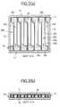
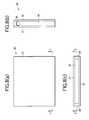
- FIGS. 1 ( a ), ( b ), and ( c )illustrate a heat transfer apparatus with a zigzag pipe according to a first embodiment of the present invention; (a) being a plan view thereof, (b) being a side view thereof, and (c) being a front view thereof.
- FIGS. 2 ( a ) and ( b )illustrate the interior structure of the heat transfer apparatus with the zigzag pipe according to the first embodiment of the present invention; (a) being a cross sectional view thereof taken along the line G—G of FIG. 1 ( c ) and ( b ) being a cross sectional view taken along line H—H of FIG. 1 ( a ).
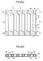
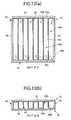
- FIGS. 3 ( a ) and ( b )illustrate a bent plate in the heat transfer apparatus with the zigzag pipe according to the first embodiment; (a) being a plan view thereof and (b) being a front view thereof.
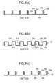
- FIGS. 4 ( a ), ( b ), and ( c )illustrate a cross-sectional shape of the bent plate in the heat transfer apparatus with the zigzag pipe according to the first embodiment; (a) being a cross-sectional view taken along the line X—X of FIG. 3 ( a ), ( b ) being a cross-sectional view taken along the line Y—Y of FIG. 3 ( b ), and ( c ) being a cross-sectional view taken along the line Z—Z of FIG. 3 ( a ).
- FIG. 5is a plan view illustrating a die of a press mold for pressing the bent plate for the heat transfer apparatus with the zigzag pipe according to the first embodiment.
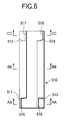
- FIG. 6is a plan view illustrating a punch of the press die for pressing the bent plate for the heat transfer apparatus with the zigzag pipe according to the first embodiment.
- FIGS. 7 ( a ), ( b ), and ( c )illustrate the press die for pressing the bent plate for the heat transfer apparatus with the zigzag pipe according to the first embodiment; (a) being a cross sectional view illustrating a combination of the section DD—DD of FIG. 5 and the section AA—AA of FIG. 6, (b) being a cross sectional view illustrating a combination of the section EE—EE of FIG. 5 and the section BB—BB of FIG. 6, and (c) being a cross sectional view illustrating a combination of the section FF—FF of FIG. 5 and the section CC—CC of FIG. 6 .
- FIGS. 8 ( a ), ( b ), and ( c )illustrate a heat transfer apparatus with a zigzag pipe according to a second embodiment of the present invention; (a) being a plan view thereof, (b) being a side view thereof, and (c) being a front view thereof.
- FIGS. 9 ( a ) and ( b )illustrate the internal structure of the heat transfer apparatus with the zigzag pipe according to the second embodiment; (a) being a cross sectional view taken along the line S—S of FIGS. 8 ( c ) and ( b ) being a cross sectional view taken along the line T—T of FIG. 8 ( a ).
- FIGS. 10 ( a ) and ( b )illustrate a bent plate for the heat transfer apparatus with the zigzag pipe according to the second embodiment; (a) being a plan view thereof and (b) being a front view thereof.
- FIGS. 11 ( a ), ( b ), and ( c )illustrate the cross sectional shape of the bent plate for the heat transfer apparatus with the zigzag pipe according to the second embodiment; (a) being a cross sectional view taken along the line F—F of FIG. 10 ( a ), ( b ) being a cross sectional view taken along the line E—E of FIG. 10 ( b ), and (c) being a cross sectional view taken along the line D—D of FIG. 10 ( a ).
- FIGS. 12 ( a ), ( b ), and ( c )illustrate a heat transfer apparatus with a zigzag pipe according to a third embodiment of the present invention; (a) being a plan view thereof, (b) being a side view thereof, and (c) being a front view thereof.
- FIGS. 13 ( a ) and ( b )illustrate the interior structure of the heat transfer apparatus with the zigzag pipe according to the third embodiment; (a) being a cross sectional view taken along the line R—R of FIGS. 12 ( c ) and ( b ) being a cross sectional view taken along the line Q—Q of FIG. 12 ( a ).
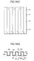
- FIGS. 14 ( a ) and ( b )illustrate a bent plate for the heat transfer apparatus with the zigzag pipe according to the third embodiment; (a) being a plan view thereof and (b) being a front view thereof.
- FIG. 15is a partially enlarged view including a partially cross sectional view of the bent plate for the heat transfer apparatus with the zigzag pipe according to the third embodiment.
- FIGS. 16 ( a ), ( b ), and ( b )illustrate a heat transfer apparatus with a zigzag pipe according to a fourth embodiment of the present invention (a) being a plan view thereof, (b) being a side view thereof, and (c) being a front view thereof.
- FIGS. 17 ( a ) and ( b )illustrate the interior structure of the heat transfer apparatus with the zigzag pipe according to the fourth embodiment; (a) being a cross sectional view taken along the line M—M of FIGS. 16 ( c ) and ( b ) being cross sectional view taken along the line N—N of FIG. 16 ( a ).
- FIG. 18is a perspective view illustrating an example of a conventional heat transfer apparatus with a zigzag pipe.
- FIG. 19is a perspective view illustrating another example of the conventional heat transfer apparatus with the zigzag pipe.
- FIGS. 1 to 4are views illustrating a heat transfer apparatus with a zigzag passage according to a first embodiment of the present invention.
- FIGS. 5 to 7are views illustrating a press mold for pressing the parts for the apparatus.
- a heat transfer apparatus 10 with a zigzag passageis, for example, a flat plate-type heat exchanger, comprising a pair of rectangular opposed plates 11 , 12 spaced apart from each other in parallel.
- the heat transfer apparatus 10 with a zigzag passagealso comprises first cover members 13 , 14 (a pair of cover members) interposed between the pair of the opposed plates 11 , 12 so as to enclose opposite two sides of the heat transfer apparatus 10 with a zigzag passage.
- the heat transfer apparatus 10 with a zigzag passagecomprises second cover members 15 , 16 provided on both end sides of the first cover members 13 , 14 so as to enclose the other two sides of the heat transfer apparatus 10 with a zigzag passage.
- At least one of the opposed plates 11 , 12forms a heat transfer surface through which heat transfers from a heat generating portion of an electronic device.
- the opposed plates 11 , 12 and the cover members 13 , 14 , 15 , 16are brazed with brazing filler metal or bonded with adhesive.
- a bent plate 21is provided between the opposed plates 11 , 12 .
- a thin plate of predetermined metalsuch as an aluminum alloy or copper
- the bent plate 21divides the space between the pair of the opposed plates 11 , 12 into a first side-by-side passage portion 20 a through which a fluid flows downwardly and a second side-by-side passage portion 20 b (a plurality of side-by-side passages) through which the fluid flows upwardly.
- the bent plate 21has a wavy cross-sectional shape which forms alternately rectangular grooves 21 a , 21 b placed opposite to each other as shown in FIG. 4 .
- the bent plate 21has different wavy cross-sectional shapes at one end portion 22 in the direction of the length of the rectangular grooves 21 a , 21 b , at an intermediate portion 23 , and at the other end portion 24 .
- the intermediate portion 23 of the bent plate 21defines the first side-by-side passage portion 20 a and the second side-by-side passage portion 20 b in parallel to each other.
- the intermediate portion 23 of the bent plate 21has both sidewall portions 23 a , 23 b and a bottom wall portion 23 c of the rectangular grooves 21 a or 21 b .
- both sidewall portions 23 a , 23 b and the bottom wall portion 23 care orthogonal to each other but may be at an angle to each other.
- the bent plate 21has a cut line provided on both ends of the intermediate portion 23 in a direction orthogonal to the rectangular grooves 21 a , 21 b , allowing both end portions 22 , 24 to be formed in a cross-sectional shape different from that of the intermediate portion 23 .
- the intermediate portion 23is provided with a cross-sectional shape of rectangular waves having the same amplitude and wavelength every half a cycle.
- both end portions 22 , 24are the same as the intermediate portion 23 in cycle of the waveform.
- the widths of adjacent crestsare equal to each other and the widths of adjacent troughs are equal to each other in half a cycle.
- half a cycle of the crestis narrowed down to approximately two times the thickness of the plate but the half a cycle of the trough is widened.
- the pair of the first cover members 13 , 14is tightly bonded to the bent plate 21 via aluminum plates 19 a , 19 b , for example, having a brazing filler metal on both surfaces thereof at both end sides of the rectangular grooves 21 a , 21 b , thereby forming connecting portions 20 c , 20 d of the side-by-side passage portions 20 a , 20 b .
- the side-by-side passage portions 20 a , 20 b and the connecting portions 20 c , 20 dform a zigzag passage 20 which is alternately folded in opposite directions as one unit.
- One end of the zigzag passage 20communicates with a fluid inlet 17 formed on one of the second cover member 15 .
- the other end of the zigzag passage 20communicates with a fluid outlet 18 formed on the other second cover member 16 .
- one end portion 22 of the bent plate 21comprises one side wall extended portion 22 a which extends one sidewall portion 23 a of the intermediate portion 23 toward one end.
- One end portion 22also comprises one bottom wall extended portion 22 c , which extends the bottom wall portion 23 c of the intermediate portion 23 toward one end at one of the crest or trough of the waveform of the bent plate 21 , for example, at the trough in FIG. 4 ( c ).
- one end portion 22comprises a plate-shaped coupling portion 22 b coupled to one side wall extended portion 22 a at the crest (any one of crest or trough of the waveform of the bent plate 21 ) shown in the figure and coupled to one bottom wall extended portion 22 c at the trough.
- the plate-shaped coupling portion 22 bis folded from the side wall extended portion 22 a at the crest of the waveform of the bent plate 21 so as to face the side wall extended portion 22 a of the adjacent rectangular groove 21 a or 21 b , thereby coupling integrally the side wall extended portion 22 a and the bottom wall extended portion 22 c.
- the other end portion 24 of the bent plate 21comprises the other side of a side wall extended portion 24 b which extends the other sidewall portion 23 b of the intermediate portion 23 toward one end.
- the other end portion 24also comprises the other bottom wall extended portion 24 c which extends the bottom wall portion 23 c of the intermediate portion 23 toward the other end at any one of the crest or trough of the waveform of the bent plate 21 , for example, at the trough in FIG. 4 ( a ).
- the other end portion 24comprises a plate-shaped coupling portion 24 a coupled to the other side wall extended portion 24 b at the crest (any other crest or trough of the waveform of the bent plate 21 ) shown in the figure and coupled to one bottom wall extended portion 24 c at the trough.
- the plate-shaped coupling portion 24 ais folded from the side wall extended portion 24 b at the crest of the waveform of the bent plate 21 so as to face the side wall extended portion 24 b of the adjacent rectangular groove 21 a or 21 b , thereby coupling integrally the side wall extended portion 24 b and the bottom wall extended portion 24 c.
- one side wall extended portion 22 a and the other side wall extended portion 24 bprotrude opposite to each other from the intermediate portion 23 of the bent plate 21 .
- One side wall extended portion 22 ais coupled to one end side of cover member 13 of the rectangular grooves 21 a , 21 b in conjunction with one bottom wall extended portion 22 c and the plate-shaped coupling portion 22 b .
- the other side wall extended portion 24 bis coupled to the other cover member 14 of the rectangular grooves 21 a , 21 b in conjunction with the other bottom wall extended portion 24 c and the plate-shaped coupling portion 24 a .
- the connecting portions 20 c , 20 d between adjacent passages of the zigzag passage 20are thereby formed in the general shape of the Japanese syllabic character “ ⁇ ”, respectively.
- the bottom wall extended portions 22 c , 24 care extended sideways toward the side wall extended portions 22 a , 24 b of the adjacent rectangular grooves 21 a , 21 b to be formed in the general shape of the letter “L”.
- the portion extended sideways of the bottom wall extended portions 22 c , 24 c and said side wall extended portions 22 a , 24 b of the adjacent rectangular grooves 21 a , 21 bare integrally coupled to each other by the plate-shaped coupling portions 22 b , 24 a facing the side wall extended portions 22 a , 24 b of said adjacent rectangular grooves.
- one side wall extended portion 22 a of the rectangular groovesis integrally formed with another side wall extended portion via one bottom wall extended portion 22 c and the other side wall extended portion 24 b of rectangular grooves is integrally formed with another side wall extended portion via the other bottom wall extended portion 24 c.
- a punch 510 having shearing tooth portions 511 , 512 , 513 , 514 and bent portion 515 , 516 , 517 , 518 and a die 520 having shearing tooth portions 521 , 522 , 523 and bent portion 525 , 526 , 527 , 528are opened and closed in the mold in the two-way directions shown by the arrow of FIG. 7 .
- a flat-plate shaped metallic raw material(a flat plate raw material) is fed in between the punch 510 and the die 520 by one cycle of the waveform of the bent plate 21 to be pressed successively. This allows the flat-plate shaped metallic raw material to be plastically formed successively into a generally rectangular waveform having the rectangular grooves 21 a , 21 b , thereby making the bent plate 21 .
- the bent plate 21can be formed into a waveform shape by plastic pressing and then can be easily bonded to flat plates 11 , 12 , thus providing an easy method and reducing the cost of manufacture. Furthermore, bent plate 21 can provide sufficient bonding strength since the bent plate 21 can be bonded to opposite plates at a wide area using the bottom wall portion of the rectangular grooves 21 a , 21 b . Moreover, the sidewall portions 23 a , 23 b which are the ribs between the adjacent passage portions 20 a , 20 b are provided with the thickness of the plate-shaped material forming the bent plate 21 , thereby making them thin and sturdy.
- the bent plate 21is provided with the one and other side wall extended portions 22 a , 24 b , which protrude opposite to each other from the intermediate portion 23 , and the bottom wall extended portions 22 c , 24 c on both ends of the intermediate portion 23 . This facilitates the attachment (for example, brazing) of the first cover members 13 , 14 .
- one side wall extended portion 22 ais integrated with another side wall extended portion via one bottom wall extended portion 22 c and the other side wall extended portion 24 b is integrated with another side wall extended portion via the other bottom wall extended portion 24 c .
- Thisallows the bent plate 21 to be provided with no projections and allows the opposed plates 11 , 12 and the first cover members 13 , 14 to be readily bonded to one another, thereby providing ease in of handling. Moreover, it is made possible to shear and bend the bent plate 21 by pressing or the like.
- FIGS. 8 tollare views illustrating a heat transfer apparatus with a zigzag passage according to a second embodiment of the present invention.
- a heat transfer apparatus 30 with a zigzag passagecomprises a pair of opposed plates 31 , 32 , first cover members 33 , 34 (a pair of cover members) interposed between the opposed plates 31 , 32 , and second cover members 35 , 36 provided on both ends of the first cover members 33 , 34 . There is also provided a bent plate 41 between the opposed plates 31 , 32 . As shown in FIG.
- the bent plate 41divides the space between the pair of the opposed plates 31 , 32 into a first side-by-side passage portion 40 a through which a fluid flows downwardly and a second side-by-side passage portion 40 b (a plurality of side-by-side passages) through which the fluid flows upwardly.
- the bent plate 41has a wavy cross-sectional shape which forms alternately rectangular grooves 41 a , 41 b placed opposite to each other as shown in FIGS. 10 and 11 ( b ).
- the bent plate 41has different wavy cross-sectional shapes individually bent at one end portion 42 in the direction of the length of the rectangular grooves 41 a , 41 b , at an intermediate portion 43 , and at the other end portion 44 and are bonded to one another.
- the intermediate portion 43 of the bent plate 41forms the rectangular groove 41 a and 41 b , opposite to each other, for defining the first side-by-side passage portion 40 a and the second side-by-side passage portion 40 b in parallel.
- the intermediate portion 43 of the bent plate 41is provided with a general rectangular wave cross-sectional shape comprising both sidewall portions 43 a , 43 b and a bottom wall portion 43 c of the rectangular grooves 41 a and 41 b .
- one end portion 42 and the other end portion 44 of the bent plate 41each are formed in a generally rectangular wave cross-sectional shape having a wavelength two times the waveform of the intermediate portion 43 .
- One end portion 42 and the other end portion 44have a positional relationship in a waveform shifted by half the wavelength of the waveform of the intermediate portion 43 .
- one end portion 42 of the bent plate 41comprises one side wall extended portion 42 a which extends one sidewall portion 43 a of the intermediate portion 43 toward one end.
- One end portion 42also comprises one bottom wall extended portion 42 c which extends the bottom wall portion 43 c of the intermediate portion 43 toward one end at one of the crest or trough of the waveform of the bent plate 41 , for example, at the trough in FIG. 11 ( a ).
- the other end portion 44 of the bent plate 41comprises the other side wall extended portion 44 b which extends the other sidewall portion 43 b of the intermediate portion 43 toward one end.
- the other end portion 44also comprises the other bottom wall extended portion 44 c which extends the bottom wall portion 43 c of the intermediate portion 43 toward one end at one of the crest or trough of the waveform of the bent plate 41 , for example, at the trough in FIG. 11 ( c ).
- one bottom wall extended portion 42 c and one side wall extended portion 42 aare coupled to the cover member 33 on one end of the rectangular grooves 41 a , 41 b .
- the other bottom wall extended portion 44 c and the other side wall extended portion 44 bare coupled to the cover member 34 on the other end of the rectangular grooves 41 a , 41 b . Folded portions 40 c , 40 d of a zigzag passage 40 are thereby formed.
- the bent plate 41can be easily manufactured by pressing.
- the sidewall portions 43 a , 43 bwhich are ribs between the adjacent passages 40 a , 40 b are provided with the thickness of the plate-shape material forming the bent plate 41 , thereby providing the same effect as the aforementioned embodiment.
- this embodimentalso allows one bottom wall extended portion 42 c and one side wall extended portion 42 a to be coupled to the cover member 33 on one end, and the other bottom wall extended portion 44 c and the other side wall extended portion 44 b to be coupled to the cover member 34 on the other end. This facilitates the attachment of the cover members 33 , 34 .
- FIGS. 12 to 15are views illustrating a heat transfer apparatus with a zigzag passage according to a third embodiment of the present invention.
- a heat transfer apparatus 50 with a zigzag passagecomprises a pair of opposed plates 51 , 52 , first cover members 53 , 54 (a pair of cover members) interposed between the opposed plates 51 , 52 , and second cover members 55 , 56 provided on both ends of the first cover members 53 , 54 .
- the bent plate 61divides the space between the pair of the opposed plates 51 , 52 into a first side-by-side passage portion 60 a through which a fluid flows downwardly and a second side-by-side passage portion 60 b (a plurality of side-by-side passages) through which the fluid flows upwardly.
- the bent plate 61has a wavy cross-sectional shape which forms alternately rectangular grooves 61 a , 61 b placed opposite to each other as shown in FIGS. 14 and 15.
- the bent plate 61has one end portion 62 in the direction of the length of the rectangular grooves 61 a , 61 b , an intermediate portion 63 , and the other end portion 64 . These are allowed to form the rectangular grooves 61 a , 61 b , opposite to each other, for defining the first side-by-side passage portion 60 a and the second side-by-side passage portion 60 b .
- the intermediate portion 63is provided with a general rectangular wave cross-sectional shape comprising both sidewall portions 63 a , 63 b and a bottom wall portion 63 c of the rectangular grooves 61 a or 61 b.
- one end portion 62 and the other end portion 64 of the bent plate 61have one communicating notch portion 62 d obtained by partially cutting off one end of one of both sidewall portions 63 a , 63 b of each of the rectangular grooves 61 a , 61 b or one sidewall portion 63 a , and the other communicating notch portion 64 d obtained by partially cutting off the other end of one of both sidewall portions 63 a , 63 b of each of the rectangular grooves 61 a , 61 b or the other sidewall portion 63 b .
- One end portion 62 and the other end portion 64 of the bent plate 61 , where the communicating notch portions 62 d , 64 d are formed,are coupled to the cover members 53 , 54 via adhesive layers 59 a , 59 b to form folded portions 60 c , 60 d of a zigzag passage 60 .
- the bent plate 61can be easily manufactured by pressing. Moreover, the sidewall portions 63 a , 63 b or ribs between the adjacent passages 60 a , 60 b are provided with the thickness of the plate-shape material forming the bent plate 61 , thereby providing the same effect as the aforementioned embodiment.
- FIGS. 16 and 17are views illustrating a heat transfer apparatus with a zigzag passage according to a fourth embodiment of the present invention.
- a heat transfer apparatus 70 with a zigzag passagecomprises a pair of opposed plates 71 , 72 , first cover members 73 , 74 (a pair of cover members) interposed between the opposed plates 71 , 72 , and second cover members 75 , 76 provided on both ends of the first cover members 73 , 74 .
- the bent plate 81divides the space between the pair of the opposed plates 71 , 72 into a first side-by-side passage portion 80 a through which a fluid flows downwardly in FIG.
- the bent plate 81has a wavy cross-sectional shape which forms alternately rectangular grooves 81 a , 81 b placed opposite to each other as shown in FIG. 17 ( b ).
- the bent plate 81has a general rectangular wave cross-sectional shape comprising both sidewall portions 83 a , 83 b and a bottom wall portion 83 c of the rectangular grooves 81 a or 81 b .
- the bent plate 81is coupled to the cover members 73 , 74 on both ends thereof.
- Recessed portions 73 a , 74 ahaving a circular arc bottom surface formed on the cover members 73 , 74 , form folded portions 80 c , 80 d of a zigzag passage 80 .
- the bent plate 81can be easily manufactured by pressing. Moreover, the sidewall portions 83 a , 83 b or ribs between the adjacent passages 80 a , 80 b are provided with the thickness of the plate-shape material forming the bent plate 81 , thereby providing the same effect as the aforementioned embodiment.
- a cooling apparatus or the heat transfer apparatus 10 with the zigzag passage, for circulating cold water through the zigzag passage 20can be easily manufactured in the following steps. That is, the bent plate 21 is formed of a plate of an aluminum alloy (of thickness 0.1 mm) specified in JIS H 4000 A3003P. Then, the bent plate 21 is abutted to the opposed plates 11 , 12 formed of a brazing sheet (an aluminum plate with brazing filler metal) specified in JIS Z 3263 BAS121P and to the cover members 13 - 16 formed of an aluminum alloy plate (JIS H 4000 A3003P). Then, they are heated up to 590 to 605° C. to be brazed to each other. Thus, the heat transfer apparatus 10 with a zigzag passage can be manufactured.
- a brazing sheetan aluminum plate with brazing filler metal
- a cooling apparatus or the heat transfer apparatus 50 with a zigzag passage for circulating cold water through the zigzag passagecan be easily manufactured in the following steps. That is, the bent plate 61 is formed of a stainless steel plate having a thickness of 0.5 mm. Then, the bent plate 61 is provided by electric discharge machining with the communicating notch portions 62 d , 64 d for connecting adjacent passages to each other. Thereafter, the bent plate 61 is abutted to the opposed plates 51 , 52 formed of a stainless steel plate and the cover members 53 - 56 to be bonded to each other with adhesive. Thus, the heat transfer apparatus 50 with a zigzag passage can be manufactured.
- a cooling apparatus or the heat transfer apparatus 30 with the zigzag passage for circulating cold water through the zigzag passage 40can be easily manufactured in the following steps. That is, the bent plate 41 is formed of a copper plate having a thickness of 0.1 mm. Then, the bent plate 41 is abutted to the opposed plates 31 , 32 formed of copper and the cover members 33 - 36 . They are heated up and brazed to bond to each other. Thus, the heat transfer apparatus 30 with a zigzag passage can be manufactured.
- the aforementioned embodiments and examplesare configured as a heat exchanger for circulating a liquid such as cold water as a heat medium through the zigzag passage.
- the present inventionis not limited to cooling use.
- all of the aforementioned embodiments and examplesare flat plate-type heat transfer apparatuses with a zigzag passage.
- the side-by-side arrangement(which is not necessarily a parallel arrangement) of the side-by-side passages is maintained in the shape of a curved heat transfer surface of the opposed plates, it is also possible to make the side-by-side surface curved or bent.
- a plurality of adjacent side-by-side passagesmay be curved in the same direction to be arranged side by side.
- one side wall portion of both side wall portions of the rectangular grooves of the bent plateis coupled to one end of the cover members of the rectangular grooves.
- the other side wall portion of both side wall portions of the rectangular groovesis coupled to the other end of the cover members of the rectangular grooves.
- a zigzag passageis formed in which one side of each of the rectangular grooves is folded to oppose the other side of its rectangular groove, thus making it possible to easily form the bent plate of a flat plate material by pressing.
- the thickness of said side wall portion which is a rib between adjacent passagescan be made thin and sturdy, thereby making it possible to narrow the spacing between the adjacent passages and raising the heat transfer efficiency.
- the bent platecan be easily and positively bonded to the opposed plates over a wide area using the bottom wall portion of the rectangular grooves, thereby making it possible to provide sufficient bonding strength.
Landscapes
- Engineering & Computer Science (AREA)
- Physics & Mathematics (AREA)
- General Engineering & Computer Science (AREA)
- Thermal Sciences (AREA)
- Mechanical Engineering (AREA)
- Sustainable Development (AREA)
- Life Sciences & Earth Sciences (AREA)
- Condensed Matter Physics & Semiconductors (AREA)
- General Physics & Mathematics (AREA)
- Computer Hardware Design (AREA)
- Microelectronics & Electronic Packaging (AREA)
- Power Engineering (AREA)
- Cooling Or The Like Of Electrical Apparatus (AREA)
- Cooling Or The Like Of Semiconductors Or Solid State Devices (AREA)
- Heat-Exchange Devices With Radiators And Conduit Assemblies (AREA)
Abstract
Description
The present invention relates to heat transfer apparatuses with a zigzag passage and more particularly to a heat transfer apparatus with a zigzag passage which can be effectively used for plate-type heat exchangers or zigzag heat pipes.
Conventionally, to cool down electronic devices, an air cooling system has been frequently used with heat radiation members (heat sinks) such as fins that are in close contact with the heat generating portion of the devices. However, when heat cannot be dissipated desirably into the air and a high level of cooling is required, a forced cooling device that employs a liquid such as water having a high specific heat is used instead of or in conjunction with the air cooling system. In the latter case, frequently used is a plate-type heat exchanger which can be easily handled and readily brought into contact with a heat generating portion of the electronic device.
The plate-type heat exchanger of this type includes one with a zigzag pipe shown in FIG.18 and another with plates affixed thereto shown in FIG.19. First, the plate-type heat exchanger with a zigzag pipe shown in FIG. 18 has a metallic pipe with good heat conductivity, which has a predetermined diameter and is formed into a zigzag pipe in the same plane by folding the pipe in a U-shaped configuration at given lengths. A plate or plates with good heat conductivity are brazed to one or both sides of the zigzag pipe. On the other hand, the one shown in FIG. 19 has a zigzag groove which is folded at a given length of the groove in the general shape of the letter “U” or rectangle at least on one plane of the opposite surfaces of a pair of plates. The plates are affixed to each other to form a zigzag passage.
In addition, though not shown, such a heat exchanger is also known in which a raw metal sheet is pressed to form a plate with projections (ridges) for forming passages. A pair of the plates having a target shape is brazed to each other at the top end portion of the projections (ridges) to form the passages.
However, the aforementioned heat transfer apparatus with a zigzag passage could not allow a metal pipe to be bent in a zigzag manner with a small curvature at the U-turn portions. (For example, a pipe of pure copper cannot be provided with a minimum bending radius approximately 1.5 times the outer diameter of the pipe.) Accordingly, this allowed the pitch of adjacent passages to be narrowed within limitation.
In addition, to provide grooves requiring a depth for the plates, it was considerably difficult to make the wall between adjacent grooves thinner than approximately 0.5 mm in thickness, by general cutting methods from the viewpoint of cutting cost and durability.
Furthermore, taking pressed plates to be brazed to each other at the top end portion of the projections (ridges). In this case, a certain width is required of the abutting joint portion of the projections (ridges). This caused adjacent passages to be spaced apart by the amount of the joint width and therefore the pitch between adjacent passages could be narrowed within limitation.
As described above, it was difficult to narrow the pitch between adjacent fluid passages of the conventional plate-type heat transfer apparatus. Therefore, the cooling area (heat exchange area) per unit heat transfer area could be enlarged with limitation, thereby making it impossible to improve heat transfer efficiency and causing an increase in cost due to the difficulty of cutting.
In view of the aforementioned circumstances, the present invention is to realize a simple zigzag piping structure which allows the walls between adjacent passages to be made thinner and sturdy and thereby provide a low-cost heat transfer apparatus having a good heat efficiency.
To solve the aforementioned problems, a heat transfer apparatus with a zigzag passage according to a preferred embodiment of the present invention comprises a pair of opposed plates opposite to each other with at least one of the pair of the opposed plates forming a heat transfer surface; a bent plate, having a wavy cross-sectional shape, for forming rectangular grooves opposite to each other in a cross section of the passage so as to divide a space between said opposed plates into a plurality of side-by-side passages; and a pair of cover members bonded to said bent plate at both ends of the rectangular grooves of said bent plate and forming connecting portions between said side-by-side passages. The heat transfer apparatus with a zigzag passage is characterized in that one side wall portion of both side wall portions of the rectangular grooves of said bent plate is coupled to one end cover member of said rectangular grooves, the other side wall portion of both side wall portions of said rectangular grooves is coupled to the cover member on the other end of said rectangular grooves, and thus a zigzag passage is formed in which one side of the rectangular groove is folded to oppose the other side of the rectangular groove. In this configuration, the bent plate can be easily manufactured by pressing or the like. In addition, said side wall portion or a rib between adjacent passages is provided with a thickness of the plate-shaped material for forming the bent plate, thereby being made thin and sturdy. This allows the spacing between adjacent passages to be narrowed. Furthermore, the bent plate can be bonded to the opposed plates at a wide area using the bottom wall portion of said rectangular grooves, thereby making it possible to provide a sufficient bonding strength.
In the aforementioned heat transfer apparatus with a zigzag passage, it is preferable that on any one of a crest or trough of a waveform of said bent plate, provided are one bottom wall extended portion formed by extending the bottom wall portion of said rectangular grooves toward both ends and another bottom wall extended portion; said one side wall portion is extended to one side of said rectangular grooves and said other side wall portion is extended to the other end of said rectangular grooves to provide one side wall extended portion and another bottom wall extended portion; and said one bottom wall extended portion and said one side wall extended portion are coupled to the cover members on one end of said rectangular grooves and said other bottom wall extended portion and said other side wall extended portion are coupled to a cover member on the other side of said rectangular grooves. In this configuration, the bent plate is provided with the side wall extended portion and the bottom wall extended portion, thereby making it possible to facilitate the attachment of the cover members.
In this case, it is more preferable that said bottom wall extended portion is extended sideward of the side wall extended portion of adjacent rectangular grooves, a portion extended sideward of said bottom wall extended portion and said side wall extended portion of the adjacent rectangular grooves are integrally coupled to each other by a plate-shaped coupling portion opposite to the side wall extended portion of the adjacent rectangular grooves; and said one side wall extended portion is integrally formed via said one bottom wall extended portion as well as said other side wall extended portion is integrally formed via said other bottom wall extended portion. In this configuration, the bent plate is provided with no projections, and allows the opposed plates and the cover members to be readily bonded thereto and easily handled. Moreover, it is made possible to shear and bend the bent plate by pressing or the like.
The present disclosure relates to the subject matter contained in Japanese patent application No. 2000-47961 (filed on Feb. 24, 2000), which is expressly incorporated herein by reference in its entirety.
FIGS.1(a), (b), and (c) illustrate a heat transfer apparatus with a zigzag pipe according to a first embodiment of the present invention; (a) being a plan view thereof, (b) being a side view thereof, and (c) being a front view thereof.
FIGS.2(a) and (b) illustrate the interior structure of the heat transfer apparatus with the zigzag pipe according to the first embodiment of the present invention; (a) being a cross sectional view thereof taken along the line G—G of FIG. 1 (c) and (b) being a cross sectional view taken along line H—H of FIG.1(a).
FIGS.3(a) and (b) illustrate a bent plate in the heat transfer apparatus with the zigzag pipe according to the first embodiment; (a) being a plan view thereof and (b) being a front view thereof.
FIGS.4(a), (b), and (c) illustrate a cross-sectional shape of the bent plate in the heat transfer apparatus with the zigzag pipe according to the first embodiment; (a) being a cross-sectional view taken along the line X—X of FIG.3(a), (b) being a cross-sectional view taken along the line Y—Y of FIG.3(b), and (c) being a cross-sectional view taken along the line Z—Z of FIG.3(a).
FIG. 5 is a plan view illustrating a die of a press mold for pressing the bent plate for the heat transfer apparatus with the zigzag pipe according to the first embodiment.
FIG. 6 is a plan view illustrating a punch of the press die for pressing the bent plate for the heat transfer apparatus with the zigzag pipe according to the first embodiment.
FIGS.7(a), (b), and (c) illustrate the press die for pressing the bent plate for the heat transfer apparatus with the zigzag pipe according to the first embodiment; (a) being a cross sectional view illustrating a combination of the section DD—DD of FIG.5 and the section AA—AA of FIG. 6, (b) being a cross sectional view illustrating a combination of the section EE—EE of FIG.5 and the section BB—BB of FIG. 6, and (c) being a cross sectional view illustrating a combination of the section FF—FF of FIG.5 and the section CC—CC of FIG.6.
FIGS.8(a), (b), and (c) illustrate a heat transfer apparatus with a zigzag pipe according to a second embodiment of the present invention; (a) being a plan view thereof, (b) being a side view thereof, and (c) being a front view thereof.
FIGS.9(a) and (b) illustrate the internal structure of the heat transfer apparatus with the zigzag pipe according to the second embodiment; (a) being a cross sectional view taken along the line S—S of FIGS.8(c) and (b) being a cross sectional view taken along the line T—T of FIG.8(a).
FIGS.10(a) and (b) illustrate a bent plate for the heat transfer apparatus with the zigzag pipe according to the second embodiment; (a) being a plan view thereof and (b) being a front view thereof.
FIGS.11(a), (b), and (c) illustrate the cross sectional shape of the bent plate for the heat transfer apparatus with the zigzag pipe according to the second embodiment; (a) being a cross sectional view taken along the line F—F of FIG.10(a), (b) being a cross sectional view taken along the line E—E of FIG. 10 (b), and (c) being a cross sectional view taken along the line D—D of FIG.10(a).
FIGS.12(a), (b), and (c) illustrate a heat transfer apparatus with a zigzag pipe according to a third embodiment of the present invention; (a) being a plan view thereof, (b) being a side view thereof, and (c) being a front view thereof.
FIGS.13(a) and (b) illustrate the interior structure of the heat transfer apparatus with the zigzag pipe according to the third embodiment; (a) being a cross sectional view taken along the line R—R of FIGS.12(c) and (b) being a cross sectional view taken along the line Q—Q of FIG.12(a).
FIGS.14(a) and (b) illustrate a bent plate for the heat transfer apparatus with the zigzag pipe according to the third embodiment; (a) being a plan view thereof and (b) being a front view thereof.
FIG. 15 is a partially enlarged view including a partially cross sectional view of the bent plate for the heat transfer apparatus with the zigzag pipe according to the third embodiment.
FIGS.16(a), (b), and (b) illustrate a heat transfer apparatus with a zigzag pipe according to a fourth embodiment of the present invention (a) being a plan view thereof, (b) being a side view thereof, and (c) being a front view thereof.
FIGS.17(a) and (b) illustrate the interior structure of the heat transfer apparatus with the zigzag pipe according to the fourth embodiment; (a) being a cross sectional view taken along the line M—M of FIGS.16(c) and (b) being cross sectional view taken along the line N—N of FIG.16(a).
FIG. 18 is a perspective view illustrating an example of a conventional heat transfer apparatus with a zigzag pipe.
FIG. 19 is a perspective view illustrating another example of the conventional heat transfer apparatus with the zigzag pipe.
The preferred embodiments of the present invention will be explained below with reference to the drawings.
[First Embodiment]
FIGS. 1 to4 are views illustrating a heat transfer apparatus with a zigzag passage according to a first embodiment of the present invention. FIGS. 5 to7 are views illustrating a press mold for pressing the parts for the apparatus.
As shown in FIGS. 1 to3, aheat transfer apparatus 10 with a zigzag passage is, for example, a flat plate-type heat exchanger, comprising a pair of rectangular opposedplates heat transfer apparatus 10 with a zigzag passage also comprisesfirst cover members 13,14 (a pair of cover members) interposed between the pair of theopposed plates heat transfer apparatus 10 with a zigzag passage. Moreover, theheat transfer apparatus 10 with a zigzag passage comprisessecond cover members first cover members heat transfer apparatus 10 with a zigzag passage. Here, at least one of theopposed plates opposed plates cover members
In addition, abent plate 21 is provided between theopposed plates bent plate 21 in a wave shape. As shown in FIG. 2, thebent plate 21 divides the space between the pair of theopposed plates side passage portion 20athrough which a fluid flows downwardly and a second side-by-side passage portion 20b(a plurality of side-by-side passages) through which the fluid flows upwardly. In a cross section of the side-by-side passage portions bent plate 21 has a wavy cross-sectional shape which forms alternatelyrectangular grooves
More specifically, thebent plate 21 has different wavy cross-sectional shapes at oneend portion 22 in the direction of the length of therectangular grooves intermediate portion 23, and at theother end portion 24. Theintermediate portion 23 of thebent plate 21 defines the first side-by-side passage portion 20aand the second side-by-side passage portion 20bin parallel to each other. Moreover, theintermediate portion 23 of thebent plate 21 has bothsidewall portions bottom wall portion 23cof therectangular grooves sidewall portions bottom wall portion 23care orthogonal to each other but may be at an angle to each other.
As shown in FIG. 3, thebent plate 21 has a cut line provided on both ends of theintermediate portion 23 in a direction orthogonal to therectangular grooves end portions intermediate portion 23. In addition, as shown in FIG.4(b), theintermediate portion 23 is provided with a cross-sectional shape of rectangular waves having the same amplitude and wavelength every half a cycle. In contrast, as shown in FIGS.4(a) and (c), bothend portions intermediate portion 23 in cycle of the waveform. That is, the widths of adjacent crests are equal to each other and the widths of adjacent troughs are equal to each other in half a cycle. However, half a cycle of the crest is narrowed down to approximately two times the thickness of the plate but the half a cycle of the trough is widened.
The pair of thefirst cover members bent plate 21 viaaluminum plates rectangular grooves portions side passage portions side passage portions portions zigzag passage 20 which is alternately folded in opposite directions as one unit. One end of thezigzag passage 20 communicates with afluid inlet 17 formed on one of thesecond cover member 15. The other end of thezigzag passage 20 communicates with afluid outlet 18 formed on the othersecond cover member 16.
Incidentally, as shown in FIGS.3 and4(c), oneend portion 22 of thebent plate 21 comprises one side wall extendedportion 22awhich extends onesidewall portion 23aof theintermediate portion 23 toward one end. Oneend portion 22 also comprises one bottom wall extendedportion 22c, which extends thebottom wall portion 23cof theintermediate portion 23 toward one end at one of the crest or trough of the waveform of thebent plate 21, for example, at the trough in FIG.4(c). Moreover, oneend portion 22 comprises a plate-shapedcoupling portion 22bcoupled to one side wall extendedportion 22aat the crest (any one of crest or trough of the waveform of the bent plate21) shown in the figure and coupled to one bottom wall extendedportion 22cat the trough. Here, the plate-shapedcoupling portion 22bis folded from the side wall extendedportion 22aat the crest of the waveform of thebent plate 21 so as to face the side wall extendedportion 22aof the adjacentrectangular groove portion 22aand the bottom wall extendedportion 22c.
Similarly, as shown in FIGS.3 and4(a), theother end portion 24 of thebent plate 21 comprises the other side of a side wall extendedportion 24bwhich extends theother sidewall portion 23bof theintermediate portion 23 toward one end. Theother end portion 24 also comprises the other bottom wall extendedportion 24cwhich extends thebottom wall portion 23cof theintermediate portion 23 toward the other end at any one of the crest or trough of the waveform of thebent plate 21, for example, at the trough in FIG.4(a). Moreover, theother end portion 24 comprises a plate-shapedcoupling portion 24acoupled to the other side wall extendedportion 24bat the crest (any other crest or trough of the waveform of the bent plate21) shown in the figure and coupled to one bottom wall extendedportion 24cat the trough. Here, the plate-shapedcoupling portion 24ais folded from the side wall extendedportion 24bat the crest of the waveform of thebent plate 21 so as to face the side wall extendedportion 24bof the adjacentrectangular groove portion 24band the bottom wall extendedportion 24c.
In addition, one side wall extendedportion 22aand the other side wall extendedportion 24bprotrude opposite to each other from theintermediate portion 23 of thebent plate 21. One side wall extendedportion 22ais coupled to one end side ofcover member 13 of therectangular grooves portion 22cand the plate-shapedcoupling portion 22b. The other side wall extendedportion 24bis coupled to theother cover member 14 of therectangular grooves portion 24cand the plate-shapedcoupling portion 24a. The connectingportions zigzag passage 20 are thereby formed in the general shape of the Japanese syllabic character “⊃”, respectively.
That is, in this embodiment, the bottom wall extendedportions portions rectangular grooves portions portions rectangular grooves coupling portions portions portion 22aof the rectangular grooves is integrally formed with another side wall extended portion via one bottom wall extendedportion 22cand the other side wall extendedportion 24bof rectangular grooves is integrally formed with another side wall extended portion via the other bottom wall extendedportion 24c.
Here, the pressing of thebent plate 21 is explained. As shown in FIGS. 5 to7, apunch 510 havingshearing tooth portions bent portion die 520 havingshearing tooth portions bent portion punch 510 and thedie 520 by one cycle of the waveform of thebent plate 21 to be pressed successively. This allows the flat-plate shaped metallic raw material to be plastically formed successively into a generally rectangular waveform having therectangular grooves bent plate 21.
As described above, in this embodiment, thebent plate 21 can be formed into a waveform shape by plastic pressing and then can be easily bonded toflat plates bent plate 21 can provide sufficient bonding strength since thebent plate 21 can be bonded to opposite plates at a wide area using the bottom wall portion of therectangular grooves sidewall portions adjacent passage portions bent plate 21, thereby making them thin and sturdy. Consequently, this makes it possible to provide a sufficient area for cooling the passages per unit heat transfer area and thus improve the heat transfer efficiency. Furthermore, forming holes or notches for folding the passage on both ends of thebent plate 21 and punching are not required in an additional step, thereby reducing the time of the manufacture.
Furthermore, in theheat transfer apparatus 10 with a zigzag passage according to this embodiment, thebent plate 21 is provided with the one and other side wall extendedportions intermediate portion 23, and the bottom wall extendedportions intermediate portion 23. This facilitates the attachment (for example, brazing) of thefirst cover members
In addition, one side wall extendedportion 22ais integrated with another side wall extended portion via one bottom wall extendedportion 22cand the other side wall extendedportion 24bis integrated with another side wall extended portion via the other bottom wall extendedportion 24c. This allows thebent plate 21 to be provided with no projections and allows the opposedplates first cover members bent plate 21 by pressing or the like.
[Second Embodiment]
FIGS. 8 toll are views illustrating a heat transfer apparatus with a zigzag passage according to a second embodiment of the present invention.
As shown in FIGS. 8 to11, aheat transfer apparatus 30 with a zigzag passage according to the second embodiment comprises a pair ofopposed plates first cover members 33,34 (a pair of cover members) interposed between theopposed plates second cover members first cover members bent plate 41 between theopposed plates bent plate 41 divides the space between the pair of theopposed plates side passage portion 40athrough which a fluid flows downwardly and a second side-by-side passage portion 40b(a plurality of side-by-side passages) through which the fluid flows upwardly. In a cross section of the side-by-side passage portions bent plate 41 has a wavy cross-sectional shape which forms alternatelyrectangular grooves
More specifically, thebent plate 41 has different wavy cross-sectional shapes individually bent at oneend portion 42 in the direction of the length of therectangular grooves intermediate portion 43, and at theother end portion 44 and are bonded to one another. In addition, theintermediate portion 43 of thebent plate 41 forms therectangular groove side passage portion 40aand the second side-by-side passage portion 40bin parallel. For this purpose, theintermediate portion 43 of thebent plate 41 is provided with a general rectangular wave cross-sectional shape comprising bothsidewall portions bottom wall portion 43cof therectangular grooves end portion 42 and theother end portion 44 of thebent plate 41 each are formed in a generally rectangular wave cross-sectional shape having a wavelength two times the waveform of theintermediate portion 43. Oneend portion 42 and theother end portion 44 have a positional relationship in a waveform shifted by half the wavelength of the waveform of theintermediate portion 43.
Furthermore, as shown in FIGS. 10 and 11 (a), oneend portion 42 of thebent plate 41 comprises one side wall extendedportion 42awhich extends onesidewall portion 43aof theintermediate portion 43 toward one end. Oneend portion 42 also comprises one bottom wall extendedportion 42cwhich extends thebottom wall portion 43cof theintermediate portion 43 toward one end at one of the crest or trough of the waveform of thebent plate 41, for example, at the trough in FIG.11(a). Likewise, as shown in FIGS.10 and11(a), theother end portion 44 of thebent plate 41 comprises the other side wall extendedportion 44bwhich extends theother sidewall portion 43bof theintermediate portion 43 toward one end. Theother end portion 44 also comprises the other bottom wall extendedportion 44cwhich extends thebottom wall portion 43cof theintermediate portion 43 toward one end at one of the crest or trough of the waveform of thebent plate 41, for example, at the trough in FIG. 11 (c). In addition, one bottom wall extendedportion 42cand one side wall extendedportion 42aare coupled to thecover member 33 on one end of therectangular grooves portion 44cand the other side wall extendedportion 44bare coupled to thecover member 34 on the other end of therectangular grooves portions zigzag passage 40 are thereby formed.
In this embodiment, thebent plate 41 can be easily manufactured by pressing. Moreover, thesidewall portions adjacent passages bent plate 41, thereby providing the same effect as the aforementioned embodiment. Furthermore, this embodiment also allows one bottom wall extendedportion 42cand one side wall extendedportion 42ato be coupled to thecover member 33 on one end, and the other bottom wall extendedportion 44cand the other side wall extendedportion 44bto be coupled to thecover member 34 on the other end. This facilitates the attachment of thecover members
[Third Embodiment]
FIGS. 12 to15 are views illustrating a heat transfer apparatus with a zigzag passage according to a third embodiment of the present invention.
As shown in FIGS. 12 and 13, aheat transfer apparatus 50 with a zigzag passage according to the third embodiment comprises a pair ofopposed plates first cover members 53,54 (a pair of cover members) interposed between theopposed plates second cover members first cover members bent plate 61 between theopposed plates bent plate 61 divides the space between the pair of theopposed plates side passage portion 60athrough which a fluid flows downwardly and a second side-by-side passage portion 60b(a plurality of side-by-side passages) through which the fluid flows upwardly. In a cross section of the side-by-side passage portions bent plate 61 has a wavy cross-sectional shape which forms alternatelyrectangular grooves
More specifically, thebent plate 61 has oneend portion 62 in the direction of the length of therectangular grooves intermediate portion 63, and theother end portion 64. These are allowed to form therectangular grooves side passage portion 60aand the second side-by-side passage portion 60b. For this purpose, theintermediate portion 63 is provided with a general rectangular wave cross-sectional shape comprising bothsidewall portions bottom wall portion 63cof therectangular grooves
Furthermore, as shown in FIG. 15, oneend portion 62 and theother end portion 64 of thebent plate 61 have one communicatingnotch portion 62dobtained by partially cutting off one end of one of bothsidewall portions rectangular grooves sidewall portion 63a, and the other communicatingnotch portion 64dobtained by partially cutting off the other end of one of bothsidewall portions rectangular grooves other sidewall portion 63b. Oneend portion 62 and theother end portion 64 of thebent plate 61, where the communicatingnotch portions cover members adhesive layers portions zigzag passage 60.
In this embodiment, thebent plate 61 can be easily manufactured by pressing. Moreover, thesidewall portions adjacent passages bent plate 61, thereby providing the same effect as the aforementioned embodiment.
[Fourth Embodiment]
FIGS. 16 and 17 are views illustrating a heat transfer apparatus with a zigzag passage according to a fourth embodiment of the present invention.
As shown in FIGS. 16 and 17, aheat transfer apparatus 70 with a zigzag passage according to the fourth embodiment comprises a pair ofopposed plates first cover members 73,74 (a pair of cover members) interposed between theopposed plates second cover members first cover members bent plate 81 between theopposed plates bent plate 81 divides the space between the pair of theopposed plates side passage portion 80athrough which a fluid flows downwardly in FIG. 13 and a second side-by-side passage portion 80b(a plurality of side-by-side passages) through which the fluid flows upwardly. In a cross section of the side-by-side passage portions bent plate 81 has a wavy cross-sectional shape which forms alternatelyrectangular grooves
More specifically, thebent plate 81 has a general rectangular wave cross-sectional shape comprising bothsidewall portions bottom wall portion 83cof therectangular grooves bent plate 81 is coupled to thecover members portions cover members portions zigzag passage 80.
In this embodiment, thebent plate 81 can be easily manufactured by pressing. Moreover, thesidewall portions adjacent passages bent plate 81, thereby providing the same effect as the aforementioned embodiment.
A cooling apparatus or theheat transfer apparatus 10 with the zigzag passage, for circulating cold water through thezigzag passage 20 can be easily manufactured in the following steps. That is, thebent plate 21 is formed of a plate of an aluminum alloy (of thickness 0.1 mm) specified in JIS H 4000 A3003P. Then, thebent plate 21 is abutted to theopposed plates heat transfer apparatus 10 with a zigzag passage can be manufactured.
A cooling apparatus or theheat transfer apparatus 50 with a zigzag passage for circulating cold water through the zigzag passage can be easily manufactured in the following steps. That is, thebent plate 61 is formed of a stainless steel plate having a thickness of 0.5 mm. Then, thebent plate 61 is provided by electric discharge machining with the communicatingnotch portions bent plate 61 is abutted to theopposed plates heat transfer apparatus 50 with a zigzag passage can be manufactured.
A cooling apparatus or theheat transfer apparatus 30 with the zigzag passage for circulating cold water through thezigzag passage 40 can be easily manufactured in the following steps. That is, thebent plate 41 is formed of a copper plate having a thickness of 0.1 mm. Then, thebent plate 41 is abutted to theopposed plates heat transfer apparatus 30 with a zigzag passage can be manufactured.
Incidentally, the aforementioned embodiments and examples are configured as a heat exchanger for circulating a liquid such as cold water as a heat medium through the zigzag passage. However, as a matter of course, the present invention is not limited to cooling use. Furthermore, it is also possible to form a zigzag heating pipe for conducting heat for averaging the temperature from a lower to a higher temperature portion on the plate as a configuration for filling a working fluid of two phases of gas and liquid into the zigzag passage and sealing the zigzag passage.
Furthermore, all of the aforementioned embodiments and examples are flat plate-type heat transfer apparatuses with a zigzag passage. However, while the side-by-side arrangement (which is not necessarily a parallel arrangement) of the side-by-side passages is maintained in the shape of a curved heat transfer surface of the opposed plates, it is also possible to make the side-by-side surface curved or bent. In addition, a plurality of adjacent side-by-side passages may be curved in the same direction to be arranged side by side.
According to the present invention, one side wall portion of both side wall portions of the rectangular grooves of the bent plate is coupled to one end of the cover members of the rectangular grooves. The other side wall portion of both side wall portions of the rectangular grooves is coupled to the other end of the cover members of the rectangular grooves. A zigzag passage is formed in which one side of each of the rectangular grooves is folded to oppose the other side of its rectangular groove, thus making it possible to easily form the bent plate of a flat plate material by pressing. The thickness of said side wall portion which is a rib between adjacent passages can be made thin and sturdy, thereby making it possible to narrow the spacing between the adjacent passages and raising the heat transfer efficiency. Furthermore, the bent plate can be easily and positively bonded to the opposed plates over a wide area using the bottom wall portion of the rectangular grooves, thereby making it possible to provide sufficient bonding strength.
Claims (12)
1. A heat transfer apparatus with a zigzag passage comprising:
a pair of opposed plates at least one plate of the pair of opposed plates forming a heat transfer surface,
a bent plate having a wavy cross-sectional shape forming rectangular grooves alternately opposite to each other in a cross section of the zigzag passage so as to divide a space between said pair of opposed plates into a plurality of side-by-side passages, wherein said bent plate includes side wall portions so that each adjacent pair of the side wall portions defines a rectangular groove therebetween, and
a pair of cover members bonded to said bent plate at both ends of the rectangular grooves of said bent plate and forming connecting portions between said side-by-side passages,
wherein one side wall portion of said adjacent pair of side wall portions is coupled to one cover member of said pair of cover members, and an other side wall portion of said adjacent pair of side wall portions is coupled to an other cover member of said pair of cover members, so that the zigzag passage has a flow direction from one of the rectangular grooves to an adjacent rectangular groove, the flow direction changed at one of the ends of said one of the rectangular grooves, and
wherein both ends of each rectangular groove form an end portion, and only one of the two end portions of each groove is coupled to a corresponding cover member of said pair of cover members in one side wall portion of each rectangular groove.
2. The heat transfer apparatus according toclaim 1 , wherein
on any one of a crest or a trough of a waveform of said bent plate, provided are one bottom wall extended portion and an other bottom wall extended portion, the bottom wall extended portions formed by extending a bottom wall portion of said rectangular grooves toward both ends of said rectangular grooves,
said one side wall portion is extended to one end of said rectangular grooves and said other side wail portion is extended to an other end of said rectangular grooves to provide one side wall extended portion and an other side wall extended portion, and
said one bottom wall extended portion and said one side wall extended portion are coupled to one cover member of the pair of cover members on the one end of said rectangular grooves and said other bottom wall extended portion and said other side wall extended portion are coupled to the other cover member of the pair of covet member on the other end of said rectangular grooves.
3. The heat transfer apparatus according toclaim 2 , wherein
said bottom wail extended portions are extended sideward of the corresponding side wall extended portions of the adjacent rectangular grooves, a portion extended sidewall of said bottom wall extended portions and said corresponding side wall extended portions of the adjacent rectangular grooves are integrally coupled to each other by a plate-shaped coupling portion opposite to the corresponding side wall extended portions of the adjacent rectangular grooves, and
said side wall extended portions are integrally formed with said corresponding bottom wall extended portions.
4. A heat transfer apparatus with a zigzag passage, comprising:
a pair of opposed plates having surfaces;
a one-piece wavy plate interposed between the pair of opposed plates, the one-piece wavy plate including:
an intermediate portion having a first wavy cross section defining and partitioning side-by-side passages, in a first direction substantially parallel to the surfaces of the pair of opposed plates;
a first end portion having a second wavy cross section communicating one tad of each of the side-by-side passages with a corresponding end of an adjacent passage; and
a second end portion having a third wavy cross section communicating an other end of the side-by-side passages with a corresponding other end of an adjacent passage;
a first pair of cover members located opposite to each other in a second direction perpendicular to the first direction, one cover member attached to the first end portion and an other cover member attached to the second end portion, and
first and second side wall portions defining a rectangular groove corresponding to each side-by-side passage, wherein only one of the two side wall portions is coupled to one cover member of said pair of cover members at one end of each rectangular groove.
5. The heat transfer apparatus according toclaim 4 , further comprising:
a second pair of cover members, one cover member having a fluid inlet, the other cover member having a fluid outlet, wherein the second pair of cover members are located opposite to each other, generally parallel to the side-by-side passages and attached to the first cover members.
6. The heat transfer apparatus ofclaim 1 , wherein only one of the two side wall portions is coupled to one cover member of said pair of cover members at one end of each rectangular groove.
7. A heat transfer apparatus with a zigzag passage comprising:
a pair of opposed plates at least one plate of the pair of opposed plates forming a heat transfer surface,
a bent plate having a wavy cross-sectional shape forming rectangular grooves alternately opposite to each other in a cross section of the zigzag passage so as to divide a space between said pair of opposed plates into a plurality of side-by-side passages, wherein said bent plate includes side wall portions so that each adjacent pair of the side wall portions defines a rectangular groove therebetween, and
a pair of cover members bonded to said bent plate at both ends of the rectangular grooves of said bent plate and forming connecting portions between said side-by-side passages,
wherein one side wall onion of said adjacent pair of side wall portions is coupled to one cover member of said pair of cover members, and an other side wall portion of said adjacent pair of side wall portions is coupled to an other cover member of said pair of cover members, so that the zigzag passage has a flow direction from one of the rectangular grooves to an adjacent rectangular groove, the flow direction chan ed at one of the ends of said one of the rectangular grooves, and
wherein the flow directions are opposite to each other in each adjacent side-by-side passage.
8. The heat transfer apparatus ofclaim 4 , the wavy plate further including first and second side wall portions defining a rectangular groove corresponding to each side-by-side passage, wherein only one of the two end portions is coupled to a corresponding cover member of said pair of cover members in one side wall portion of each rectangular groove.
9. The heat transfer apparatus ofclaim 4 , wherein the flow directions are opposite to each other in each adjacent side-by-side passage.
10. The heat transfer apparatus according toclaim 7 , wherein
on any one of a crest or a trough of a waveform of said bent plate, provided are one bottom wall extended portion and an other bottom wall extended portion, the bottom wall extended portions formed by extending a bottom wall portion of said rectangular grooves toward both ends of said rectangular grooves,
said one side wail portion is extended to one end of said rectangular grooves and said other side wall portion is extended to an other end of said rectangular grooves to provide one side wall extended portion and an other side wall extended portion, and
said one bottom wall extended portion and said one side wall extended portion are coupled to one cover member of the pair of cover members on the one end of said rectangular grooves and said other bottom wall extended portion and said other side wall extended portion are coupled to the other cover member of the pair of cover member on the other end of said rectangular grooves.
11. The heat transfer apparatus according toclaim 10 , wherein
said bottom wall extended portions are extended sideward of the corresponding side wall extended portions of the adjacent rectangular grooves, a portion extended sideward of said bottom wall extended portions and said corresponding side wall extended portions of the adjacent rectangular grooves are integrally coupled to each other by a plate-shaped coupling portion opposite to the corresponding side wall extended portions of the adjacent rectangular grooves, and
said side wail extended portions are integrally formed with said corresponding bottom wall extended portions.
12. The heat transfer apparatus ofclaim 7 , wherein only one of the two side wall portions is coupled to one cover member of said pair of cover members at one end of each rectangular groove.
Applications Claiming Priority (3)
| Application Number | Priority Date | Filing Date | Title |
|---|---|---|---|
| JP2000047961AJP4312339B2 (en) | 2000-02-24 | 2000-02-24 | Heat transfer device with meandering passage |
| JPP2000-047961 | 2000-02-24 | ||
| JPP2000-47961 | 2000-02-24 |
Publications (2)
| Publication Number | Publication Date |
|---|---|
| US20010045276A1 US20010045276A1 (en) | 2001-11-29 |
| US6729389B2true US6729389B2 (en) | 2004-05-04 |
Family
ID=18570122
Family Applications (1)
| Application Number | Title | Priority Date | Filing Date |
|---|---|---|---|
| US09/791,183Expired - Fee RelatedUS6729389B2 (en) | 2000-02-24 | 2001-02-23 | Heat transfer apparatus with zigzag passage |
Country Status (2)
| Country | Link |
|---|---|
| US (1) | US6729389B2 (en) |
| JP (1) | JP4312339B2 (en) |
Cited By (23)
| Publication number | Priority date | Publication date | Assignee | Title |
|---|---|---|---|---|
| US20030098588A1 (en)* | 2001-11-26 | 2003-05-29 | Kazuaki Yazawa | Method and apparatus for converting dissipated heat to work energy |
| US20030173068A1 (en)* | 2000-12-21 | 2003-09-18 | Davies Michael E. | Finned plate heat exchanger |
| US20040238162A1 (en)* | 2003-04-11 | 2004-12-02 | Seiler Thomas F. | Heat exchanger with flow circuiting end caps |
| US20050115701A1 (en)* | 2003-11-28 | 2005-06-02 | Michael Martin | Low profile heat exchanger with notched turbulizer |
| US7025127B2 (en)* | 2002-07-05 | 2006-04-11 | Dana Canada Corporation | Baffled surface cooled heat exchanger |
| US20070137843A1 (en)* | 2005-09-28 | 2007-06-21 | Josef Gievers | Heat exchanger core and heat exchanger equipped therewith |
| US20080029260A1 (en)* | 2006-08-02 | 2008-02-07 | Man Zai Industrial Co., Ltd. | Liquid cooled heat sink |
| US20080031773A1 (en)* | 2006-08-03 | 2008-02-07 | Terumo Cardiovascular Systems Corporation | Thermoelectric temperature control for extracorporeal blood circuit |
| US20080060796A1 (en)* | 2006-09-12 | 2008-03-13 | Ying Lin Cai | Heat exchange device for hot water of shower and bath |
| US20080078539A1 (en)* | 2006-09-29 | 2008-04-03 | Cao Ai Guo | Air conditioner heat transfer water tank and manufacturing process thereof |
| EP2377596A1 (en) | 2010-04-14 | 2011-10-19 | Kaeser Kompressoren GmbH | Refrigerant type dryer, in particular pressurised air refrigerant type dryer and heat exchanger for a refrigerant type dryer, in particular pressurised air refrigerant type dryer |
| US8077974B2 (en) | 2006-07-28 | 2011-12-13 | Hewlett-Packard Development Company, L.P. | Compact stylus-based input technique for indic scripts |
| US20120125587A1 (en)* | 2010-11-24 | 2012-05-24 | Ying Lin Cai | Heat exchanger for bathing shower |
| US20140033771A1 (en)* | 2012-01-09 | 2014-02-06 | Owens-Brockway Glass Container Inc. | Batch Charger Cooling |
| US20140069615A1 (en)* | 2011-05-12 | 2014-03-13 | Toyota Jidosha Kabushiki Kaisha | Cooler and method for producing the same |
| US20220087053A1 (en)* | 2020-09-14 | 2022-03-17 | City University Of Hong Kong | Heat sink with counter flow diverging microchannels |
| US11280561B2 (en)* | 2020-02-06 | 2022-03-22 | Ldc Precision Engineering Co., Ltd. | Current stabilization and pressure boosting device for evaporator |
| US11333450B2 (en)* | 2018-07-05 | 2022-05-17 | Nexson Group | Plate for heat exchanger and heat exchanger including the plate |
| US11396470B2 (en)* | 2016-08-25 | 2022-07-26 | Johns Manville | Continuous flow submerged combustion melter cooling wall panels, submerged combustion melters, and methods of using same |
| US11744044B2 (en)* | 2020-11-05 | 2023-08-29 | Deeia, Inc. | Loop thermosyphon devices and systems, and related methods |
| US11852387B2 (en) | 2019-02-28 | 2023-12-26 | Lg Electronics, Inc. | Refrigerator |
| WO2024056772A1 (en)* | 2022-09-16 | 2024-03-21 | Robert Bosch Gmbh | Heat exchanger for cooling components |
| WO2024251715A1 (en)* | 2023-06-07 | 2024-12-12 | Robert Bosch Gmbh | Heat pipe heat sink |
Families Citing this family (21)
| Publication number | Priority date | Publication date | Assignee | Title |
|---|---|---|---|---|
| JP4485013B2 (en)* | 2000-05-16 | 2010-06-16 | ティーエス ヒートロニクス 株式会社 | Plate type heat pipe and manufacturing method thereof |
| EP1375475A1 (en) | 2002-06-28 | 2004-01-02 | Urea Casale S.A. | Plant for urea production |
| TWI287700B (en)* | 2004-03-31 | 2007-10-01 | Delta Electronics Inc | Heat dissipation module |
| EP1782883A1 (en)* | 2005-11-08 | 2007-05-09 | Methanol Casale S.A. | Isothermal chemical reactor |
| JP4891617B2 (en)* | 2006-01-05 | 2012-03-07 | 株式会社ティラド | Water-cooled heat sink |
| GB2434633A (en)* | 2006-01-27 | 2007-08-01 | Boc Group Plc | Freeze dryer shelf comprising a corrugated sheet defining a flow channel |
| JP5343574B2 (en)* | 2009-01-20 | 2013-11-13 | トヨタ自動車株式会社 | Brazing method of heat sink |
| KR101164158B1 (en)* | 2009-08-13 | 2012-07-11 | 웅진코웨이주식회사 | Water purifier with ice maker |
| ITVE20090013U1 (en)* | 2009-10-01 | 2011-04-02 | Tec Sim S R L | PLATE FOR LYO-FILTERING MACHINES. |
| JP5807351B2 (en)* | 2011-03-16 | 2015-11-10 | 株式会社富士通ゼネラル | Heat exchanger |
| KR101267015B1 (en) | 2011-10-26 | 2013-05-30 | 히트텍(주) | Cooler for electrical and electronic equipment |
| CN103975432B (en)* | 2011-12-21 | 2018-01-02 | 南京皓赛米电力科技有限公司 | The encapsulating structure and technique of microchannel direct copper substrate and its power device |
| JP5968425B2 (en)* | 2012-03-30 | 2016-08-10 | 京セラ株式会社 | Channel member, heat exchanger using the same, and semiconductor device |
| WO2014017661A1 (en)* | 2012-07-27 | 2014-01-30 | 京セラ株式会社 | Flow path member, and heat exchanger and semiconductor manufacturing device using same |
| FR3008173B1 (en)* | 2013-07-08 | 2018-11-23 | Liebherr-Aerospace Toulouse Sas | THERMAL EXCHANGE DEVICE AND METHOD FOR MANUFACTURING SUCH A DEVICE |
| CN106123646A (en)* | 2016-06-27 | 2016-11-16 | 无锡锡能锅炉有限公司 | A kind of side-by-side heat exchanger for gas fired-boiler |
| JP6948832B2 (en)* | 2017-05-22 | 2021-10-13 | 株式会社Uacj鋳鍛 | Heat transfer plate for vacuum equipment and its manufacturing method |
| KR102020961B1 (en) | 2018-10-08 | 2019-09-11 | 삼익기전 주식회사 | A heat exchange assembly for an heat dissipating electronic device having improved sealing performance and thermal efficiency |
| US11818831B2 (en)* | 2019-09-24 | 2023-11-14 | Borgwarner Inc. | Notched baffled heat exchanger for circuit boards |
| CN112077547A (en)* | 2020-08-03 | 2020-12-15 | 东莞领杰金属精密制造科技有限公司 | Soaking plate structure without liquid absorption core and preparation method thereof |
| JP7184229B1 (en)* | 2021-02-04 | 2022-12-06 | 大日本印刷株式会社 | Heat exchanger |
Citations (34)
| Publication number | Priority date | Publication date | Assignee | Title |
|---|---|---|---|---|
| US47298A (en)* | 1865-04-18 | Improved cooler for breweries | ||
| US289859A (en)* | 1883-12-11 | John h | ||
| US880237A (en)* | 1907-05-24 | 1908-02-25 | Frederick P Obenauer | Water-heater. |
| US897792A (en)* | 1907-09-19 | 1908-09-01 | Samuel D Montgomery | Gas-generator. |
| US1094256A (en)* | 1912-01-30 | 1914-04-21 | Silvio Anton Schewczik | Hot-plate. |
| US1273162A (en)* | 1917-05-03 | 1918-07-23 | Wilhelm Ehmke | Cooling-coil for refrigerator-boxes. |
| US1311049A (en)* | 1919-07-22 | Evapobatdstg-pakt | ||
| US1318875A (en)* | 1919-10-14 | Henby g | ||
| US1322897A (en)* | 1919-11-25 | Chill-plate | ||
| US1527689A (en)* | 1924-02-09 | 1925-02-24 | Gen Electric | Steam plate |
| US1633271A (en)* | 1925-05-14 | 1927-06-21 | Pauly Charles | Vat |
| US1664628A (en)* | 1925-08-20 | 1928-04-03 | Farrel Foundry And Machine Co | Fluid-circulating plate |
| US1693249A (en)* | 1925-10-09 | 1928-11-27 | Pauly Charles | Vat |
| US1962954A (en)* | 1931-11-11 | 1934-06-12 | Soc Of Chemical Ind | Hollow heat exchange plate |
| US2572972A (en)* | 1947-05-06 | 1951-10-30 | Baldwin Lima Hamilton Corp | Press platen |
| US2981520A (en)* | 1959-11-09 | 1961-04-25 | Borg Warner | Plate-type heat-exchangers |
| US3181605A (en)* | 1961-06-20 | 1965-05-04 | Hupp Corp | Uniformly heated rotary drum |
| US3246689A (en)* | 1963-12-23 | 1966-04-19 | Johns Manville | Heating or cooling wall panels |
| US3327776A (en)* | 1965-10-24 | 1967-06-27 | Trane Co | Heat exchanger |
| US3621909A (en)* | 1970-08-04 | 1971-11-23 | Horace L Smith Jr | Heat exchange units and heating systems employing such units |
| US3800868A (en)* | 1972-04-14 | 1974-04-02 | Curtiss Wright Corp | Heat exchanger |
| US4085728A (en) | 1976-08-16 | 1978-04-25 | Tomchak Sigfrid A | Solar energy heater |
| US4136675A (en)* | 1976-08-09 | 1979-01-30 | Karasick Norman M | Solar collector |
| US4574876A (en)* | 1981-05-11 | 1986-03-11 | Extracorporeal Medical Specialties, Inc. | Container with tapered walls for heating or cooling fluids |
| US4801778A (en)* | 1985-03-12 | 1989-01-31 | Ngk Insulators, Ltd. | Condensation resistant electrode for use in a dielectric heating apparatus |
| US4874035A (en) | 1987-11-17 | 1989-10-17 | Shinwa Sangyo Co., Ltd. | Heat exchanger for cooling tower |
| US4903640A (en)* | 1986-11-22 | 1990-02-27 | P. Howard Industrial Pipework Services Limited | Panel adapted for coolant through flow, and an article incorporating such panels |
| US5289872A (en)* | 1993-05-21 | 1994-03-01 | General Motors Corporation | Sacrificial brackets for aluminum heat exchanger |
| GB2271630A (en) | 1992-10-17 | 1994-04-20 | Howard Ind Pipework Services L | Panel adapted for coolant through-flow and an article incorporating such panels |
| US5510207A (en)* | 1992-11-02 | 1996-04-23 | Societe Anonyme Dite Saft | Storage cell battery unit equipped with a cooling device |
| US5519946A (en)* | 1992-03-12 | 1996-05-28 | The Boc Group, Inc. | Freeze dryer shelf |
| US5642775A (en)* | 1995-02-16 | 1997-07-01 | Actronics Kabushiki Kaisha | Ribbon-like plate heat pipes |
| US6026890A (en)* | 1995-06-29 | 2000-02-22 | Actronics Kabushiki Kaisha | Heat transfer device having metal band formed with longitudinal holes |
| US6138354A (en)* | 1997-01-08 | 2000-10-31 | Denso Corporation | Method of manufacturing a corrugated plate by rolling for use as an inner fin of a heat exchanger |
Family Cites Families (3)
| Publication number | Priority date | Publication date | Assignee | Title |
|---|---|---|---|---|
| JPS56150841A (en)* | 1980-04-23 | 1981-11-21 | Hitachi Ltd | Cooling material for electric parts |
| IL93994A (en)* | 1989-04-19 | 1994-07-31 | Urch John Francis | Heat exchanger |
| JPH0694386A (en)* | 1992-09-14 | 1994-04-05 | Sanden Corp | Heat exchanger |
- 2000
- 2000-02-24JPJP2000047961Apatent/JP4312339B2/ennot_activeExpired - Lifetime
- 2001
- 2001-02-23USUS09/791,183patent/US6729389B2/ennot_activeExpired - Fee Related
Patent Citations (34)
| Publication number | Priority date | Publication date | Assignee | Title |
|---|---|---|---|---|
| US1318875A (en)* | 1919-10-14 | Henby g | ||
| US289859A (en)* | 1883-12-11 | John h | ||
| US47298A (en)* | 1865-04-18 | Improved cooler for breweries | ||
| US1322897A (en)* | 1919-11-25 | Chill-plate | ||
| US1311049A (en)* | 1919-07-22 | Evapobatdstg-pakt | ||
| US880237A (en)* | 1907-05-24 | 1908-02-25 | Frederick P Obenauer | Water-heater. |
| US897792A (en)* | 1907-09-19 | 1908-09-01 | Samuel D Montgomery | Gas-generator. |
| US1094256A (en)* | 1912-01-30 | 1914-04-21 | Silvio Anton Schewczik | Hot-plate. |
| US1273162A (en)* | 1917-05-03 | 1918-07-23 | Wilhelm Ehmke | Cooling-coil for refrigerator-boxes. |
| US1527689A (en)* | 1924-02-09 | 1925-02-24 | Gen Electric | Steam plate |
| US1633271A (en)* | 1925-05-14 | 1927-06-21 | Pauly Charles | Vat |
| US1664628A (en)* | 1925-08-20 | 1928-04-03 | Farrel Foundry And Machine Co | Fluid-circulating plate |
| US1693249A (en)* | 1925-10-09 | 1928-11-27 | Pauly Charles | Vat |
| US1962954A (en)* | 1931-11-11 | 1934-06-12 | Soc Of Chemical Ind | Hollow heat exchange plate |
| US2572972A (en)* | 1947-05-06 | 1951-10-30 | Baldwin Lima Hamilton Corp | Press platen |
| US2981520A (en)* | 1959-11-09 | 1961-04-25 | Borg Warner | Plate-type heat-exchangers |
| US3181605A (en)* | 1961-06-20 | 1965-05-04 | Hupp Corp | Uniformly heated rotary drum |
| US3246689A (en)* | 1963-12-23 | 1966-04-19 | Johns Manville | Heating or cooling wall panels |
| US3327776A (en)* | 1965-10-24 | 1967-06-27 | Trane Co | Heat exchanger |
| US3621909A (en)* | 1970-08-04 | 1971-11-23 | Horace L Smith Jr | Heat exchange units and heating systems employing such units |
| US3800868A (en)* | 1972-04-14 | 1974-04-02 | Curtiss Wright Corp | Heat exchanger |
| US4136675A (en)* | 1976-08-09 | 1979-01-30 | Karasick Norman M | Solar collector |
| US4085728A (en) | 1976-08-16 | 1978-04-25 | Tomchak Sigfrid A | Solar energy heater |
| US4574876A (en)* | 1981-05-11 | 1986-03-11 | Extracorporeal Medical Specialties, Inc. | Container with tapered walls for heating or cooling fluids |
| US4801778A (en)* | 1985-03-12 | 1989-01-31 | Ngk Insulators, Ltd. | Condensation resistant electrode for use in a dielectric heating apparatus |
| US4903640A (en)* | 1986-11-22 | 1990-02-27 | P. Howard Industrial Pipework Services Limited | Panel adapted for coolant through flow, and an article incorporating such panels |
| US4874035A (en) | 1987-11-17 | 1989-10-17 | Shinwa Sangyo Co., Ltd. | Heat exchanger for cooling tower |
| US5519946A (en)* | 1992-03-12 | 1996-05-28 | The Boc Group, Inc. | Freeze dryer shelf |
| GB2271630A (en) | 1992-10-17 | 1994-04-20 | Howard Ind Pipework Services L | Panel adapted for coolant through-flow and an article incorporating such panels |
| US5510207A (en)* | 1992-11-02 | 1996-04-23 | Societe Anonyme Dite Saft | Storage cell battery unit equipped with a cooling device |
| US5289872A (en)* | 1993-05-21 | 1994-03-01 | General Motors Corporation | Sacrificial brackets for aluminum heat exchanger |
| US5642775A (en)* | 1995-02-16 | 1997-07-01 | Actronics Kabushiki Kaisha | Ribbon-like plate heat pipes |
| US6026890A (en)* | 1995-06-29 | 2000-02-22 | Actronics Kabushiki Kaisha | Heat transfer device having metal band formed with longitudinal holes |
| US6138354A (en)* | 1997-01-08 | 2000-10-31 | Denso Corporation | Method of manufacturing a corrugated plate by rolling for use as an inner fin of a heat exchanger |
Cited By (31)
| Publication number | Priority date | Publication date | Assignee | Title |
|---|---|---|---|---|
| US20030173068A1 (en)* | 2000-12-21 | 2003-09-18 | Davies Michael E. | Finned plate heat exchanger |
| US7011142B2 (en) | 2000-12-21 | 2006-03-14 | Dana Canada Corporation | Finned plate heat exchanger |
| US20030098588A1 (en)* | 2001-11-26 | 2003-05-29 | Kazuaki Yazawa | Method and apparatus for converting dissipated heat to work energy |
| US6856037B2 (en)* | 2001-11-26 | 2005-02-15 | Sony Corporation | Method and apparatus for converting dissipated heat to work energy |
| US7025127B2 (en)* | 2002-07-05 | 2006-04-11 | Dana Canada Corporation | Baffled surface cooled heat exchanger |
| US20040238162A1 (en)* | 2003-04-11 | 2004-12-02 | Seiler Thomas F. | Heat exchanger with flow circuiting end caps |
| US7213638B2 (en) | 2003-04-11 | 2007-05-08 | Dana Canada Corporation | Heat exchanger with flow circuiting end caps |
| US20050115701A1 (en)* | 2003-11-28 | 2005-06-02 | Michael Martin | Low profile heat exchanger with notched turbulizer |
| US7182125B2 (en) | 2003-11-28 | 2007-02-27 | Dana Canada Corporation | Low profile heat exchanger with notched turbulizer |
| US20070137843A1 (en)* | 2005-09-28 | 2007-06-21 | Josef Gievers | Heat exchanger core and heat exchanger equipped therewith |
| US8077974B2 (en) | 2006-07-28 | 2011-12-13 | Hewlett-Packard Development Company, L.P. | Compact stylus-based input technique for indic scripts |
| US20080029260A1 (en)* | 2006-08-02 | 2008-02-07 | Man Zai Industrial Co., Ltd. | Liquid cooled heat sink |
| US7588549B2 (en)* | 2006-08-03 | 2009-09-15 | Terumo Cardiovascular Systems Corporation | Thermoelectric temperature control for extracorporeal blood circuit |
| US20080031773A1 (en)* | 2006-08-03 | 2008-02-07 | Terumo Cardiovascular Systems Corporation | Thermoelectric temperature control for extracorporeal blood circuit |
| US20080060796A1 (en)* | 2006-09-12 | 2008-03-13 | Ying Lin Cai | Heat exchange device for hot water of shower and bath |
| US20080078539A1 (en)* | 2006-09-29 | 2008-04-03 | Cao Ai Guo | Air conditioner heat transfer water tank and manufacturing process thereof |
| US10143962B2 (en) | 2010-04-14 | 2018-12-04 | Kaeser Kompressoren Se | Refrigerant dryer, in particular compressed air refrigerant dryer, and heat exchanger for a refrigerant dryer, in particular a compressed air refrigerant dryer |
| EP2377596A1 (en) | 2010-04-14 | 2011-10-19 | Kaeser Kompressoren GmbH | Refrigerant type dryer, in particular pressurised air refrigerant type dryer and heat exchanger for a refrigerant type dryer, in particular pressurised air refrigerant type dryer |
| US20120125587A1 (en)* | 2010-11-24 | 2012-05-24 | Ying Lin Cai | Heat exchanger for bathing shower |
| US20140069615A1 (en)* | 2011-05-12 | 2014-03-13 | Toyota Jidosha Kabushiki Kaisha | Cooler and method for producing the same |
| US8783068B2 (en)* | 2012-01-09 | 2014-07-22 | Owens-Brockway Glass Container Inc. | Batch charger cooling |
| US20140033771A1 (en)* | 2012-01-09 | 2014-02-06 | Owens-Brockway Glass Container Inc. | Batch Charger Cooling |
| US11396470B2 (en)* | 2016-08-25 | 2022-07-26 | Johns Manville | Continuous flow submerged combustion melter cooling wall panels, submerged combustion melters, and methods of using same |
| US11333450B2 (en)* | 2018-07-05 | 2022-05-17 | Nexson Group | Plate for heat exchanger and heat exchanger including the plate |
| US11852387B2 (en) | 2019-02-28 | 2023-12-26 | Lg Electronics, Inc. | Refrigerator |
| US11280561B2 (en)* | 2020-02-06 | 2022-03-22 | Ldc Precision Engineering Co., Ltd. | Current stabilization and pressure boosting device for evaporator |
| US20220087053A1 (en)* | 2020-09-14 | 2022-03-17 | City University Of Hong Kong | Heat sink with counter flow diverging microchannels |
| US11991862B2 (en)* | 2020-09-14 | 2024-05-21 | City University Of Hong Kong | Heat sink with counter flow diverging microchannels |
| US11744044B2 (en)* | 2020-11-05 | 2023-08-29 | Deeia, Inc. | Loop thermosyphon devices and systems, and related methods |
| WO2024056772A1 (en)* | 2022-09-16 | 2024-03-21 | Robert Bosch Gmbh | Heat exchanger for cooling components |
| WO2024251715A1 (en)* | 2023-06-07 | 2024-12-12 | Robert Bosch Gmbh | Heat pipe heat sink |
Also Published As
| Publication number | Publication date |
|---|---|
| JP2001237357A (en) | 2001-08-31 |
| JP4312339B2 (en) | 2009-08-12 |
| US20010045276A1 (en) | 2001-11-29 |
Similar Documents
| Publication | Publication Date | Title |
|---|---|---|
| US6729389B2 (en) | Heat transfer apparatus with zigzag passage | |
| EP1520145B1 (en) | Baffled surface cooled heat exchanger | |
| CN102084205B (en) | Plate heat exchangers especially for motor vehicles | |
| JP3405997B2 (en) | Inner fin and manufacturing method thereof | |
| US6962194B2 (en) | Brazed sheets with aligned openings and heat exchanger formed therefrom | |
| US20150083379A1 (en) | Plate heat exchanger and refrigeration cycle system including the same | |
| EP0188314B1 (en) | Method of attaching a tube to a fin | |
| EP0881449A2 (en) | Refrigerant tubes for heat exchangers | |
| US20080047696A1 (en) | Heat transfer surfaces with flanged apertures | |
| CN110849197B (en) | heat exchanger inner fins | |
| CN103575140A (en) | Compact type aluminum heat exchanger with welding pipe for power electronic equipment and battery cooling | |
| US11162742B2 (en) | Air fin for a heat exchanger | |
| JP2002170915A (en) | Water-cooled heat sink | |
| EP0952017A2 (en) | A heat exchanger device for an air conditioning system | |
| US6942024B2 (en) | Corrugated heat exchange element | |
| EP3301393B1 (en) | Heat exchanger | |
| US20060131007A1 (en) | Heat exchanger and method of manufacturing | |
| US20070255213A1 (en) | Tube and method of producing the same | |
| CN215337881U (en) | Heat exchanger | |
| US20130213616A1 (en) | Heat exchanger incorporating out-of-plane features | |
| EP2064509B1 (en) | Heat transfer surfaces with flanged apertures | |
| JP2015135894A (en) | Method of manufacturing heat exchanger fins, fins, and heat exchanger | |
| JP2006132904A (en) | Fin manufacturing method, fin, and heat exchanger using the same | |
| EP0097612A2 (en) | Heat exchanger | |
| EP4023992A1 (en) | Heat exchanger |
Legal Events
| Date | Code | Title | Description |
|---|---|---|---|
| AS | Assignment | Owner name:STS CORPORATION, JAPAN Free format text:ASSIGNMENT OF ASSIGNORS INTEREST;ASSIGNOR:OHASHI, ISAO;REEL/FRAME:011574/0432 Effective date:20010216 | |
| FEPP | Fee payment procedure | Free format text:PAYOR NUMBER ASSIGNED (ORIGINAL EVENT CODE: ASPN); ENTITY STATUS OF PATENT OWNER: LARGE ENTITY | |
| FPAY | Fee payment | Year of fee payment:4 | |
| AS | Assignment | Owner name:NABTESCO CORPORATION, JAPAN Free format text:MERGER;ASSIGNOR:STS CORPORATION;REEL/FRAME:020808/0712 Effective date:20070410 Owner name:STS CORPORATION, JAPAN Free format text:CHANGE OF NAME;ASSIGNOR:STS CORPORATION;REEL/FRAME:020808/0801 Effective date:20041001 | |
| REMI | Maintenance fee reminder mailed | ||
| LAPS | Lapse for failure to pay maintenance fees | ||
| STCH | Information on status: patent discontinuation | Free format text:PATENT EXPIRED DUE TO NONPAYMENT OF MAINTENANCE FEES UNDER 37 CFR 1.362 | |
| FP | Lapsed due to failure to pay maintenance fee | Effective date:20120504 |