US6729331B2 - Pressure regulator - Google Patents
Pressure regulatorDownload PDFInfo
- Publication number
- US6729331B2 US6729331B2US10/140,392US14039202AUS6729331B2US 6729331 B2US6729331 B2US 6729331B2US 14039202 AUS14039202 AUS 14039202AUS 6729331 B2US6729331 B2US 6729331B2
- Authority
- US
- United States
- Prior art keywords
- valve
- diaphragm
- chamber
- pressure regulator
- inlet
- Prior art date
- Legal status (The legal status is an assumption and is not a legal conclusion. Google has not performed a legal analysis and makes no representation as to the accuracy of the status listed.)
- Expired - Lifetime
Links
- 230000029058respiratory gaseous exchangeEffects0.000claimsabstractdescription35
- 239000012530fluidSubstances0.000claimsabstractdescription24
- 230000000694effectsEffects0.000claimsdescription11
- 238000007789sealingMethods0.000claimsdescription9
- 239000011324beadSubstances0.000claimsdescription5
- 239000000463materialSubstances0.000claimsdescription5
- 230000036961partial effectEffects0.000claimsdescription2
- 230000002745absorbentEffects0.000claims1
- 239000002250absorbentSubstances0.000claims1
- 239000007789gasSubstances0.000description29
- 238000013461designMethods0.000description8
- 239000013536elastomeric materialSubstances0.000description4
- 230000002093peripheral effectEffects0.000description4
- 238000010926purgeMethods0.000description4
- 230000009471actionEffects0.000description3
- 125000006850spacer groupChemical group0.000description3
- 230000008901benefitEffects0.000description2
- 238000006073displacement reactionMethods0.000description2
- 230000009189divingEffects0.000description2
- 238000004519manufacturing processMethods0.000description2
- 230000007246mechanismEffects0.000description2
- 238000000034methodMethods0.000description2
- 230000009467reductionEffects0.000description2
- 230000004044responseEffects0.000description2
- 238000012546transferMethods0.000description2
- 230000006978adaptationEffects0.000description1
- XAGFODPZIPBFFR-UHFFFAOYSA-NaluminiumChemical compound[Al]XAGFODPZIPBFFR-UHFFFAOYSA-N0.000description1
- 229910052782aluminiumInorganic materials0.000description1
- 239000004411aluminiumSubstances0.000description1
- 230000008859changeEffects0.000description1
- 238000006243chemical reactionMethods0.000description1
- 238000011109contaminationMethods0.000description1
- 238000011161developmentMethods0.000description1
- 230000008014freezingEffects0.000description1
- 238000007710freezingMethods0.000description1
- 230000002401inhibitory effectEffects0.000description1
- 210000004072lungAnatomy0.000description1
- 230000008569processEffects0.000description1
- 230000000717retained effectEffects0.000description1
- 230000035945sensitivityEffects0.000description1
- 230000003068static effectEffects0.000description1
- 238000003860storageMethods0.000description1
- 238000013022ventingMethods0.000description1
- XLYOFNOQVPJJNP-UHFFFAOYSA-NwaterSubstancesOXLYOFNOQVPJJNP-UHFFFAOYSA-N0.000description1
- 230000003245working effectEffects0.000description1
Images


Classifications
- B—PERFORMING OPERATIONS; TRANSPORTING
- B63—SHIPS OR OTHER WATERBORNE VESSELS; RELATED EQUIPMENT
- B63C—LAUNCHING, HAULING-OUT, OR DRY-DOCKING OF VESSELS; LIFE-SAVING IN WATER; EQUIPMENT FOR DWELLING OR WORKING UNDER WATER; MEANS FOR SALVAGING OR SEARCHING FOR UNDERWATER OBJECTS
- B63C11/00—Equipment for dwelling or working underwater; Means for searching for underwater objects
- B63C11/02—Divers' equipment
- B63C11/18—Air supply
- B63C11/22—Air supply carried by diver
- B63C11/2227—Second-stage regulators
- A—HUMAN NECESSITIES
- A62—LIFE-SAVING; FIRE-FIGHTING
- A62B—DEVICES, APPARATUS OR METHODS FOR LIFE-SAVING
- A62B9/00—Component parts for respiratory or breathing apparatus
- A62B9/02—Valves
- A62B9/022—Breathing demand regulators
- G—PHYSICS
- G05—CONTROLLING; REGULATING
- G05D—SYSTEMS FOR CONTROLLING OR REGULATING NON-ELECTRIC VARIABLES
- G05D16/00—Control of fluid pressure
- G05D16/04—Control of fluid pressure without auxiliary power
- G05D16/06—Control of fluid pressure without auxiliary power the sensing element being a flexible membrane, yielding to pressure, e.g. diaphragm, bellows, capsule
- G05D16/063—Control of fluid pressure without auxiliary power the sensing element being a flexible membrane, yielding to pressure, e.g. diaphragm, bellows, capsule the sensing element being a membrane
- G05D16/0644—Control of fluid pressure without auxiliary power the sensing element being a flexible membrane, yielding to pressure, e.g. diaphragm, bellows, capsule the sensing element being a membrane the membrane acting directly on the obturator
- G05D16/0663—Control of fluid pressure without auxiliary power the sensing element being a flexible membrane, yielding to pressure, e.g. diaphragm, bellows, capsule the sensing element being a membrane the membrane acting directly on the obturator using a spring-loaded membrane with a spring-loaded slideable obturator
Definitions
- a source of air, or other breathable gasstored at a high pressure in a cylinder or bottle.
- the specific storage pressures of such gasesvaries according to the nature of the gas and the particular application but, as a general rule, the stored gas pressure may vary between 1,800 psi (1.2 ⁇ 10 7 Pa) and 4,500 psi (3.1 ⁇ 10 7 Pa).
- a high pressure regulatoris usually mounted on the cylinder to provide an output (set) pressure of the order of 60-105 psi (4.1 ⁇ 10 5 -7.2 ⁇ 10 5 Pa), dependant upon the application and the particular manufacturer's design.
- the medium level output from the high pressure, or first stage, unitis applied to some form of breathing valve system.
- Such a breathing valve systemmay be provided with a diaphragm, which typically actuates some form of inlet valve to allow flow of the medium level gas pressure, supplied from the high pressure regulator, to the mouth of the user.
- the inlet valvein many established designs is an unbalanced poppet valve, which is held closed against the supply pressure through the action of a light spring and is opened by deflection of the diaphragm acting against the spring.
- a long leveris employed to operate the inlet valve, transmitting the thrust due to the deflection of the diaphragm.
- Known variationsinclude manual adjustment of the valve aperture and/or opening pressure, to suit different operating requirements or conditions.
- a disadvantage of the lever actuating design described aboveis that, due to inevitable manufacturing tolerance variations in the various components, some selective assembly and adjustments are necessary in order to tune the function of the valve unit so as to be within acceptable performance limits.
- GB 2298026discloses an alternative arrangement for a breathing valve system, in which the inlet valve is in a pressure balanced module.
- the moduleincorporates an inlet poppet valve which is as nearly perfectly balanced as is reasonable under good quality manufacturing tolerances and conditions, so that the poppet valve can be opened directly by the thrust due to the deflection of a suitably sized diaphragm, without the need for any form of lever arrangement.
- the diaphragmin order to actuate the opening of the inlet valve directly, the diaphragm is positioned opposite, and faces, the inlet valve such that, upon deflection, the diaphragm is urged against the stem of the inlet poppet valve so as to move the stem axially and consequently open the valve. Accordingly, when the valve is in an open position, a portion of the pressurised fluid flow through the valve impinges upon the underside of the diaphragm, tending to deflect the diaphragm in a direction away from the end of the poppet valve stem and thus tending to close the inlet valve, so that there is a negative feedback effect.
- a pressure regulatorsuitable for use as a breathing demand valve in various self-contained breathing apparatus, comprising a first chamber having an inlet port, the inlet port being connectable to the outlet of a pressurised fluid supply, an inlet valve being positioned within the inlet port and biased so as to seal the first chamber from the pressurised fluid supply, wherein the opening of the inlet valve can be actuated by the thrust due to the deflection of a diaphragm positioned so as to separate the first chamber from a second chamber, a baffle plate positioned in between the diaphragm and inlet port reducing negative feedback to the flow rate through the first chamber by preventing a portion of the pressurised fluid flow released through the open inlet valve from impinging upon, and consequently deflecting, the diaphragm in a direction tending to close the inlet valve.
- a convoluted diaphragmFor low pressure valve applications, it is known to provide breathing valve systems which employ a convoluted diaphragm.
- the active part of the diaphragmcan be made relatively thin and flexible, making for a sensitive diaphragm which is essential for an accurate, low pressure demand valve.
- the use of a convoluted diaphragmhas the additional advantage that, unlike a flat-type diaphragm, the effective area of a convoluted diaphragm is readily calculable, and is constant throughout its working range of movement. This feature provides functional predictability, which is essential for low pressure regulator applications.
- a problem in the use of diaphragms in any breathing demand valve application, and particularly where sensitive diaphragms are used, such as convoluted diaphragms,is that of providing a means of clamping and sealing the peripheral sealing flange of the diaphragm, without subjecting the diaphragm to the effects of stress displacement likely to cause material distortion within the diaphragm body.
- the sealing flangeis merely clamped between two surfaces.
- one or both of the clamping surfacesmay be provided with a series of annular grooves, into which flows some of the elastomeric material which forms the flange region of the diaphragm. The flow of material into these grooves serves to grip the flange region of the diaphragm and increases the degree of sealing around the periphery of the diaphragm.
- the groovesonly take up a proportion of the elastomeric flow in the flange region of the diaphragm and the remainder of the flow of elastomeric material, caused by the clamping, is into the main body of the diaphragm, which may distort the body of the diaphragm and compromise the sensitivity in the response of the diaphragm.
- a pressure regulatorsuitable for use as a breathing demand valve in various self-contained breathing apparatus, comprising a primary chamber and a convoluted diaphragm, the diaphragm being mounted within the primary chamber so as to provide a fluid tight seal around the diaphragm rim, while isolating the convoluted section of the diaphragm from distortion effects due to rim clamping or sealing forces.
- FIG. 1is a cross-sectional view of a first embodiment of a breathing demand valve according to the present invention
- FIG. 2shows a cross-sectional view of a second embodiment of a breathing demand valve according to the present invention
- FIG. 3shows a partial cross-sectional view of the diaphragm mounting arrangement in the breathing demand valves of FIGS. 1 and 2.
- FIG. 4shows a cross sectional view of a generic demand valve system according to the present invention.
- FIG. 5shows a cross section through the inlet valve module in the demand valves of FIGS. 1, 2 and 4 .
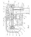
- the breathing demand valve shown in FIG. 1comprises a body 2 , a cover 16 and a diaphragm 6 clamped between the body 2 and the cover 16 .
- a first chamber 31is defined between the diaphragm 6 and the body 12 and a breathing connector tube 7 extends from this first chamber, for connection to a face mask or the like, for the supply of breathing gas to the latter.
- the breathing connector 7may be furnished with a mouthpiece or, alternatively could be connected to a half mask or full mask (not shown for the sake of clarity).
- a second chamber 39communicating with gas exhaust means.
- this second chamber 39is separated from the first chamber by the diaphragm 6 and by a flange 4 (see below).
- the body 2has an inlet connection 30 , for connecting to a supply of pressurised breathing gas, not shown, and which inlet communicates with an inlet duct 29 .
- a threaded bore in body 2extends from inlet duct 29 to said first chamber and an inlet valve module 1 , of similar form to the valve module described in GB 2298026, is screwed into the threaded bore.
- the inlet valve module 1incorporates an inlet valve member 36 which carries the flange 4 referred to above and operates to admit gas from duct 29 to said first chamber when the flange 4 is moved downwardly, (as viewed in FIG. 1 ), by deflection of the diaphragm 6 and operates to cut off the supply of gas from duct 29 to said first chamber when the flange is allowed to move upwardly, (as viewed in FIG. 1 ), by the diaphragm 6 .
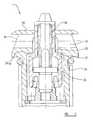
- the inlet valve module 1comprises a pressure balanced inlet valve, in the form of a poppet valve, the module comprising a valve body 34 , which is threadedly engaged in the screw-threaded bore in body 2 , and the valve member 36 which has a shoulder 36 a sealably engaging with a bead seat 37 around a valve port 35 so as to seal the first chamber 31 , (FIG. 1 ), on the low pressure side of the valve member 36 , from the pressurised gas supply on the high pressure side of the valve member 36 .
- the valve member 36may be biased towards the valve seat 37 by a light spring 38 or, if the valve is very slightly, and controllably, unbalanced, the biasing means may simply be the net pressure difference between the high and low pressure sides of the valve member.
- the inlet valve module 1differs from that disclosed in GB 2298026 only in that it further incorporates a shroud cap 32 , integral with body 34 , and which, when the valve member 36 is in the open position, diverts the pressurised gas flow from the duct 29 through radial holes 33 located at the upper end of the hollow valve body 34 , into the first chamber 31 .
- the valve member 36 of the valve module 1has a stem 3 which extends from the valve member and into the first chamber 31 along a central axis A of the screw threaded bore in body 2 , the stem 3 carrying the flange 4 at its end remote from the body 34 of the valve module 1 .
- the diaphragm 6has a central aperture forming an exhaust port 10 , and the diaphragm 6 has an elastomeric annulus surrounding the exhaust port 10 and forming a seat 5 which the upper side of the flange 4 can engage sealingly.
- the userinhales through breathing connector tube 7 , removing breathing gas from within the chamber 31 .
- the consequent net pressure difference across the diaphragmcauses deflection of the diaphragm 6 towards the inlet valve module 1 which, in turn, urges the valve seat 5 against the flange 4 and causes the flange 4 with stem 3 and the poppet valve member to move downward, opening the inlet valve 1 and allowing air to flow through the inlet valve module into the chamber 31 and thence to the user.
- the working action of the demand valveis that of a highly sensitive breath operated reactive valve similar to a pressure regulator, except that the opening thrust is produced by inhalation by the user through the breathing connector, rather than a load spring, as is the case with a pressure regulator.
- a rigid baffle plate 9 having a central aperture 40is mounted across the first chamber, below, (as viewed in FIG. 1) and generally parallel with, the diaphragm 6 .
- the stem 3extends through the central aperture 40 in the baffle plate 9 and, at least in the closed position of the inlet valve 1 , the flange 4 is located above the baffle plate 9 .
- the baffle plate 9acts to deflect the pressurised gas entering the first chamber from the inlet valve module 1 , and which would otherwise impinge upon the underside of the diaphragm 6 . Accordingly, the tendency for gas streams from the inlet valve to deflect the diaphragm 6 away from the end of the poppet valve stem 3 and thus to close the inlet valve, is largely avoided.
- a Venturi tube 24having an internal chamfer at its end opposite the baffle plate 9 , is fitted into the baffle plate 24 and extends downward from the baffle plate into the breathing connector tube 7 , lying close to the wall of the connector tube.
- Venturi tube 24tends to produce a pressure drop in the space between the diaphragm 6 and the baffle plate 9 in response to gas flow along the connector tube from the first chamber 31 , thereby counteracting the negative feedback effect referred to.
- the effectiveness of the Venturi tubein this respect has been found to be enhanced if, as illustrated, the Venturi tube is located close to the wall of the connector tube 7 .
- an increase in gas outlet flow to the usertends to produce a positive, rather than a negative feedback effect.
- the diverter cap 21is rotatable around axis A so as to be adjustable to suit the orientation of the user.
- the diverter capis preferably made from an elastomeric material, so that it may be stretched over the outside of a clamp ring 17 , and has an inwardly facing flange fitting around the underside of the clamp ring 17 .
- the diverter cap 21is held against movement along, and perpendicular to, axis A by centre boss 41 , through the engagement of inner bead 22 , on diverter cap 21 , in corresponding grooves 42 on centre boss 41 .
- the diaphragm 6comprises a central, generally flat region around the exhaust port 10 , a convoluted region around the flat region, adjacent the edges of the first and second chambers, and a flat peripheral region, surrounding the convoluted region, and a thicker edge portion or bead at the extreme periphery.
- the diaphragmis retained by the flat peripheral region being clamped between a flange 15 of top cover 16 , and an opposing annular end face of the body 2 .
- the assemblyis held closed by the clamp ring 17 .
- a spacer ring 11is interposed between the underside of the diaphragm 6 and the edge region of the baffle plate 9 , which is located between ring 11 and an opposing shoulder of the body 2 .
- a push button 18which operates a purge mechanism for the purpose of clearing fluid from within the demand valve cavity.
- the push buttonis held in the non-operative condition by spring 12 , and the purging function is effected through a pusher pin 19 acting on the top surface of flange 4 .
- the userpushes down the pusher pin 19 , which acts on the top surface of flange 4 and allows purge air to flow from the inlet valve module with the exhaust valve open, so that water which has accumulated in the body of the demand valve is purged to ambient whilst, at the same time, the pressure cannot build up to a dangerous level in the diver's lungs.
- FIG. 2shows an adaptation to the basic design, suitable for self-contained breathing apparatus used for rescue purposes in contaminated atmospheres. It is a requirement in such applications that there is, at all times, within the face mask, an ambient pressure of 1.9′′ Wg, and that breathing takes place when the suction applied by inhalation reduces the ambient pressure to no less than 0.5′′ Wg. In this way, some positive pressure is maintained in the face mask, thus keeping out any contamination.
- the ambient set pressure levelis provided by a suitably low rated load spring 26 , fitted above the diaphragm so as to produce a small deflection of the diaphragm towards the inlet valve and actuate opening of the inlet valve to a required degree.
- the load springcould be adjusted in some convenient manner so as to cause the required degree of opening of the inlet valve and set a basic ambient set-pressure level as appropriate for a specific application.
- the demand valve of FIG. 2is not provided with an exhaust valve arrangement. Instead of the exhaust flange 4 of FIG. 1, a pusher 25 is mounted on the end of the poppet valve stem 3 and engages, in turn, directly with the underside of diaphragm 6 .
- the baffle plate and Venturi tubemay be made from a good heat conducter, such as aluminium.
- the intake of heat to the baffle plate from the exhaled breathis given back on inhalation, making for more comfortable breathing and a reduction in the risk of freezing.
- the baffle plate 9is shown as a plain disc but, for equipment required to operate in extreme conditions, it is envisaged that the lower side of the baffle plate could be furnished with protrusions, which may in the form of radial vanes, in order to increase the heat transfer area.
- the baffle platemay incorporate recesses in order to increase the heat transfer area or a combination of both recesses and protrusions.
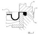
- FIG. 3shows an enlarged cross sectional view of the mounting means 55 .
- a small peripheral rim 13is located around the extremity of the sealing flange of the diaphragm.
- the rim 13has a width of around 0.5-2 mm, preferably 1-1.5 mm, and fits into a groove 13 .
- the grooveis substantially rectangular, with part of the floor 56 of the groove being chamfered at an angle of around 30-4-degrees, preferably 35 degrees.
- the chamfered floor 56 of groove 14provides a gentle wedging action which retains the rim 13 within groove 14 , providing dynamic sealing around the periphery of the rim 13 while retaining any wedging distortion in the rim 13 and the groove 14 .
- a spacer ring 1is positioned below the diaphragm flange (FIG. 1) and forms the innermost wall of groove 14 .
- the spacer ringalso serves to provide axial location of the baffle plate assembly by clamping the baffle plate against a shoulder 57 formed in body 2 .
- a pair of lugs, or some other convenient form,provides axial location of the baffle plate 9 .
- FIG. 4shows a generic demand valve according to the present invention, which illustrates the working principle.
- the designincorporates a load spring 28 , which can be adjusted by knob 27 .
- the area of the diaphragm and the load rate of the adjustment spring, along with the size and orientation of the inlet and outlet ports within the valve body,would be selected to suit the specific w application.
- Such a design of pressure regulatorcould be used to control very low pressure gases, as low as, say, 1′′ Wg.
- FIG. 4shows, for simplicity, a two-port valve configuration with no exhaust path to ambient.
- the arrangementcan easily be modified to accommodate three ports by adding an exhaust port to the centre of the diaphragm as previously described.
- suitable venting to atmospherecan be provided in a similar way to the demand valve illustrated in FIG. 1 .
- the arrangement of FIG. 4can easily be modified, by adding the required number of ports, so that the exhaust gas is introduced into the chamber and pressurised gas is removed from the chamber through separate tubes or ports.
- the “Baffle Plate and Venturi” principlecan be extended to the benefit of the design of high-pressure type regulators, where high flow performance may be required, under critical, or marginal, conditions.
- the employment of the baffle plate and Venturi tubewill, by inhibiting the feedback effect, tend to reduce the pressure drop in the static set-pressure setting under heavy breathing demand conditions. In these, systems, the resultant more stable pressure supply leads directly to a better working function.
Landscapes
- Health & Medical Sciences (AREA)
- Pulmonology (AREA)
- Physics & Mathematics (AREA)
- General Health & Medical Sciences (AREA)
- Engineering & Computer Science (AREA)
- Mechanical Engineering (AREA)
- Business, Economics & Management (AREA)
- Emergency Management (AREA)
- Ocean & Marine Engineering (AREA)
- Fluid Mechanics (AREA)
- General Physics & Mathematics (AREA)
- Automation & Control Theory (AREA)
- Control Of Fluid Pressure (AREA)
- Respiratory Apparatuses And Protective Means (AREA)
- Fuel-Injection Apparatus (AREA)
- Safety Valves (AREA)
- Fluid-Pressure Circuits (AREA)
- Valves And Accessory Devices For Braking Systems (AREA)
- Braking Systems And Boosters (AREA)
Abstract
Description
1. Field of the Invention
THIS INVENTION RELATES to a pressure regulator, particularly suitable for use as a breathing demand valve system, in, for example, diving, rescue, escape and resuscitation equipment.
There are many cases in which the need to breathe depends upon a source of air, or other breathable gas, stored at a high pressure in a cylinder or bottle. The specific storage pressures of such gases varies according to the nature of the gas and the particular application but, as a general rule, the stored gas pressure may vary between 1,800 psi (1.2×10⁷Pa) and 4,500 psi (3.1×10⁷Pa). In order to bring the stored gas pressure to a useable level, a high pressure regulator is usually mounted on the cylinder to provide an output (set) pressure of the order of 60-105 psi (4.1×10⁵-7.2×10⁵Pa), dependant upon the application and the particular manufacturer's design. The medium level output from the high pressure, or first stage, unit is applied to some form of breathing valve system.
2. Description of the Related Art
Such a breathing valve system, or demand valve, may be provided with a diaphragm, which typically actuates some form of inlet valve to allow flow of the medium level gas pressure, supplied from the high pressure regulator, to the mouth of the user. The inlet valve in many established designs is an unbalanced poppet valve, which is held closed against the supply pressure through the action of a light spring and is opened by deflection of the diaphragm acting against the spring. Conventionally, in order to obtain power gain from this design form, a long lever is employed to operate the inlet valve, transmitting the thrust due to the deflection of the diaphragm. Known variations include manual adjustment of the valve aperture and/or opening pressure, to suit different operating requirements or conditions.
A disadvantage of the lever actuating design described above is that, due to inevitable manufacturing tolerance variations in the various components, some selective assembly and adjustments are necessary in order to tune the function of the valve unit so as to be within acceptable performance limits.
GB 2298026 discloses an alternative arrangement for a breathing valve system, in which the inlet valve is in a pressure balanced module. The module incorporates an inlet poppet valve which is as nearly perfectly balanced as is reasonable under good quality manufacturing tolerances and conditions, so that the poppet valve can be opened directly by the thrust due to the deflection of a suitably sized diaphragm, without the need for any form of lever arrangement.
In the arrangement of GB 2298026, in order to actuate the opening of the inlet valve directly, the diaphragm is positioned opposite, and faces, the inlet valve such that, upon deflection, the diaphragm is urged against the stem of the inlet poppet valve so as to move the stem axially and consequently open the valve. Accordingly, when the valve is in an open position, a portion of the pressurised fluid flow through the valve impinges upon the underside of the diaphragm, tending to deflect the diaphragm in a direction away from the end of the poppet valve stem and thus tending to close the inlet valve, so that there is a negative feedback effect. For certain applications such as, for example, diving, there is a requirement for a relatively high maximum inhalation gas flow, with a predetermined inhalation suction, such that the negative feedback effect described above is considerable, and a point may be reached whereby no matter how much suction force is applied to the diaphragm, virtually no change in the mass gas flow delivered to the user can take place. This is because the higher the gas flow through the inlet valve, the greater the reaction force on the diaphragm tending to close of the inlet valve and reduce the mass gas flow.
It is an object of the present invention to provide a demand valve system which mitigates the self-limiting pressure problem described above
According to one aspect of the present invention, there is provided a pressure regulator suitable for use as a breathing demand valve in various self-contained breathing apparatus, comprising a first chamber having an inlet port, the inlet port being connectable to the outlet of a pressurised fluid supply, an inlet valve being positioned within the inlet port and biased so as to seal the first chamber from the pressurised fluid supply, wherein the opening of the inlet valve can be actuated by the thrust due to the deflection of a diaphragm positioned so as to separate the first chamber from a second chamber, a baffle plate positioned in between the diaphragm and inlet port reducing negative feedback to the flow rate through the first chamber by preventing a portion of the pressurised fluid flow released through the open inlet valve from impinging upon, and consequently deflecting, the diaphragm in a direction tending to close the inlet valve.
For low pressure valve applications, it is known to provide breathing valve systems which employ a convoluted diaphragm. The active part of the diaphragm can be made relatively thin and flexible, making for a sensitive diaphragm which is essential for an accurate, low pressure demand valve. The use of a convoluted diaphragm has the additional advantage that, unlike a flat-type diaphragm, the effective area of a convoluted diaphragm is readily calculable, and is constant throughout its working range of movement. This feature provides functional predictability, which is essential for low pressure regulator applications.
A problem in the use of diaphragms in any breathing demand valve application, and particularly where sensitive diaphragms are used, such as convoluted diaphragms, is that of providing a means of clamping and sealing the peripheral sealing flange of the diaphragm, without subjecting the diaphragm to the effects of stress displacement likely to cause material distortion within the diaphragm body.
Conventionally, the sealing flange is merely clamped between two surfaces. In a known development, one or both of the clamping surfaces may be provided with a series of annular grooves, into which flows some of the elastomeric material which forms the flange region of the diaphragm. The flow of material into these grooves serves to grip the flange region of the diaphragm and increases the degree of sealing around the periphery of the diaphragm. However, the grooves only take up a proportion of the elastomeric flow in the flange region of the diaphragm and the remainder of the flow of elastomeric material, caused by the clamping, is into the main body of the diaphragm, which may distort the body of the diaphragm and compromise the sensitivity in the response of the diaphragm.
It is a further object of the present invention to provide a demand valve system employing a diaphragm, means being provided to clamp the diaphragm while providing a substantial reduction in the transferral of the effects of stress displacement into the diaphragm, and consequent material distortion therein.
According to another aspect of the present invention there is provided a pressure regulator suitable for use as a breathing demand valve in various self-contained breathing apparatus, comprising a primary chamber and a convoluted diaphragm, the diaphragm being mounted within the primary chamber so as to provide a fluid tight seal around the diaphragm rim, while isolating the convoluted section of the diaphragm from distortion effects due to rim clamping or sealing forces.
Embodiments of the invention are described below by way of example with reference to the accompanying drawings, in which:
FIG. 1 is a cross-sectional view of a first embodiment of a breathing demand valve according to the present invention,
FIG. 2 shows a cross-sectional view of a second embodiment of a breathing demand valve according to the present invention,
FIG. 3 shows a partial cross-sectional view of the diaphragm mounting arrangement in the breathing demand valves of FIGS. 1 and 2.
FIG. 4 shows a cross sectional view of a generic demand valve system according to the present invention.
FIG. 5 shows a cross section through the inlet valve module in the demand valves of FIGS. 1,2 and4.
The breathing demand valve shown in FIG. 1 comprises abody 2, acover 16 and adiaphragm 6 clamped between thebody 2 and thecover 16. Afirst chamber 31 is defined between thediaphragm 6 and thebody 12 and a breathing connector tube7 extends from this first chamber, for connection to a face mask or the like, for the supply of breathing gas to the latter. The breathing connector7 may be furnished with a mouthpiece or, alternatively could be connected to a half mask or full mask (not shown for the sake of clarity).
There is defined between thediaphragm 6 and the cover16 asecond chamber 39 communicating with gas exhaust means. Thus thissecond chamber 39 is separated from the first chamber by thediaphragm 6 and by a flange4 (see below).
Thebody 2 has aninlet connection 30, for connecting to a supply of pressurised breathing gas, not shown, and which inlet communicates with aninlet duct 29. A threaded bore inbody 2 extends frominlet duct 29 to said first chamber and aninlet valve module 1, of similar form to the valve module described in GB 2298026, is screwed into the threaded bore.
As explained in more detail below, theinlet valve module 1 incorporates aninlet valve member 36 which carries theflange 4 referred to above and operates to admit gas fromduct 29 to said first chamber when theflange 4 is moved downwardly, (as viewed in FIG.1), by deflection of thediaphragm 6 and operates to cut off the supply of gas fromduct 29 to said first chamber when the flange is allowed to move upwardly, (as viewed in FIG.1), by thediaphragm 6.
Referring to FIG. 5, theinlet valve module 1 comprises a pressure balanced inlet valve, in the form of a poppet valve, the module comprising avalve body 34, which is threadedly engaged in the screw-threaded bore inbody 2, and thevalve member 36 which has ashoulder 36asealably engaging with abead seat 37 around avalve port 35 so as to seal thefirst chamber 31, (FIG.1), on the low pressure side of thevalve member 36, from the pressurised gas supply on the high pressure side of thevalve member 36. Thevalve member 36 may be biased towards thevalve seat 37 by alight spring 38 or, if the valve is very slightly, and controllably, unbalanced, the biasing means may simply be the net pressure difference between the high and low pressure sides of the valve member. Theinlet valve module 1 differs from that disclosed in GB 2298026 only in that it further incorporates ashroud cap 32, integral withbody 34, and which, when thevalve member 36 is in the open position, diverts the pressurised gas flow from theduct 29 throughradial holes 33 located at the upper end of thehollow valve body 34, into thefirst chamber 31.
Thevalve member 36 of thevalve module 1 has astem 3 which extends from the valve member and into thefirst chamber 31 along a central axis A of the screw threaded bore inbody 2, thestem 3 carrying theflange 4 at its end remote from thebody 34 of thevalve module 1.
Thediaphragm 6 has a central aperture forming anexhaust port 10, and thediaphragm 6 has an elastomeric annulus surrounding theexhaust port 10 and forming aseat 5 which the upper side of theflange 4 can engage sealingly.
In use, the user inhales through breathing connector tube7, removing breathing gas from within thechamber 31. The consequent net pressure difference across the diaphragm causes deflection of thediaphragm 6 towards theinlet valve module 1 which, in turn, urges thevalve seat 5 against theflange 4 and causes theflange 4 withstem 3 and the poppet valve member to move downward, opening theinlet valve 1 and allowing air to flow through the inlet valve module into thechamber 31 and thence to the user. The working action of the demand valve is that of a highly sensitive breath operated reactive valve similar to a pressure regulator, except that the opening thrust is produced by inhalation by the user through the breathing connector, rather than a load spring, as is the case with a pressure regulator.
When the user exhales, the pressure in the first chamber rises so that thediaphragm 6 moves upwards, (as viewed in FIG.1), separating from theflange 4 as the valve member in theinlet valve module 1 reaches its fully closed position, so that exhaled gas is allowed to flow to ambient via theexhaust port 10 and saidsecond chamber 39. Exhalation gas passes to ambient through shroudedradial slots 20, which are provided in thetop cover 16. Adiverter cap 21 with anexhaust vent tube 23 is fitted over thetop cover 16 to provide a means, when the valve is used for underwater applications, of diverting bubbles of exhaled gas leaving via theslots 20, away from the face of the user.
In the absence of the baffle plate provided in accordance with the invention, as described below, when theinlet valve 1 was in an open position, a portion of the pressurised gas flowing through the valve would impinge upon the underside of thediaphragm 6, tending to deflect the diaphragm in a direction away from the end of the poppet valve member and thus tending to close the inlet valve, so that there would be a negative feedback effect, as described in the introductory part of this specification. In order to avoid this effect, however, arigid baffle plate 9 having acentral aperture 40 is mounted across the first chamber, below, (as viewed in FIG. 1) and generally parallel with, thediaphragm 6. Thestem 3 extends through thecentral aperture 40 in thebaffle plate 9 and, at least in the closed position of theinlet valve 1, theflange 4 is located above thebaffle plate 9. Thebaffle plate 9 acts to deflect the pressurised gas entering the first chamber from theinlet valve module 1, and which would otherwise impinge upon the underside of thediaphragm 6. Accordingly, the tendency for gas streams from the inlet valve to deflect thediaphragm 6 away from the end of thepoppet valve stem 3 and thus to close the inlet valve, is largely avoided. AVenturi tube 24, having an internal chamfer at its end opposite thebaffle plate 9, is fitted into thebaffle plate 24 and extends downward from the baffle plate into the breathing connector tube7, lying close to the wall of the connector tube.Venturi tube 24 tends to produce a pressure drop in the space between thediaphragm 6 and thebaffle plate 9 in response to gas flow along the connector tube from thefirst chamber 31, thereby counteracting the negative feedback effect referred to. Furthermore the effectiveness of the Venturi tube in this respect has been found to be enhanced if, as illustrated, the Venturi tube is located close to the wall of the connector tube7. Thus, by contrast with what would be the situation without thebaffle plate 9 and theVenturi tube 24, an increase in gas outlet flow to the user tends to produce a positive, rather than a negative feedback effect.
Various subsidiary features of the demand valve of FIG. 1 are discussed briefly below.
Thediverter cap 21 is rotatable around axis A so as to be adjustable to suit the orientation of the user. The diverter cap is preferably made from an elastomeric material, so that it may be stretched over the outside of aclamp ring 17, and has an inwardly facing flange fitting around the underside of theclamp ring 17. Thediverter cap 21 is held against movement along, and perpendicular to, axis A by centre boss41, through the engagement of inner bead22, ondiverter cap 21, in corresponding grooves42 on centre boss41.
Thediaphragm 6 comprises a central, generally flat region around theexhaust port 10, a convoluted region around the flat region, adjacent the edges of the first and second chambers, and a flat peripheral region, surrounding the convoluted region, and a thicker edge portion or bead at the extreme periphery. The diaphragm is retained by the flat peripheral region being clamped between aflange 15 oftop cover 16, and an opposing annular end face of thebody 2. The assembly is held closed by theclamp ring 17. Aspacer ring 11 is interposed between the underside of thediaphragm 6 and the edge region of thebaffle plate 9, which is located betweenring 11 and an opposing shoulder of thebody 2.
Located in the centre oftop cover 16 is apush button 18, which operates a purge mechanism for the purpose of clearing fluid from within the demand valve cavity. The push button is held in the non-operative condition byspring 12, and the purging function is effected through apusher pin 19 acting on the top surface offlange 4. When it is required to operate the purge mechanism, the user pushes down thepusher pin 19, which acts on the top surface offlange 4 and allows purge air to flow from the inlet valve module with the exhaust valve open, so that water which has accumulated in the body of the demand valve is purged to ambient whilst, at the same time, the pressure cannot build up to a dangerous level in the diver's lungs.
FIG. 2 shows an adaptation to the basic design, suitable for self-contained breathing apparatus used for rescue purposes in contaminated atmospheres. It is a requirement in such applications that there is, at all times, within the face mask, an ambient pressure of 1.9″ Wg, and that breathing takes place when the suction applied by inhalation reduces the ambient pressure to no less than 0.5″ Wg. In this way, some positive pressure is maintained in the face mask, thus keeping out any contamination. Referring again to FIG. 2, the ambient set pressure level is provided by a suitably low rated load spring26, fitted above the diaphragm so as to produce a small deflection of the diaphragm towards the inlet valve and actuate opening of the inlet valve to a required degree. The load spring could be adjusted in some convenient manner so as to cause the required degree of opening of the inlet valve and set a basic ambient set-pressure level as appropriate for a specific application.
The demand valve of FIG. 2 is not provided with an exhaust valve arrangement. Instead of theexhaust flange 4 of FIG. 1, apusher 25 is mounted on the end of thepoppet valve stem 3 and engages, in turn, directly with the underside ofdiaphragm 6.
Upon exhalation by the user, heat exchange occurs between the users breath and thebaffle plate 9. In order to maximise this heat exchange, the baffle plate and Venturi tube may be made from a good heat conducter, such as aluminium. The intake of heat to the baffle plate from the exhaled breath is given back on inhalation, making for more comfortable breathing and a reduction in the risk of freezing. For the sake of clarity, thebaffle plate 9 is shown as a plain disc but, for equipment required to operate in extreme conditions, it is envisaged that the lower side of the baffle plate could be furnished with protrusions, which may in the form of radial vanes, in order to increase the heat transfer area. Similarly, the baffle plate may incorporate recesses in order to increase the heat transfer area or a combination of both recesses and protrusions.
FIG. 3 shows an enlarged cross sectional view of the mounting means55. A smallperipheral rim 13 is located around the extremity of the sealing flange of the diaphragm. Therim 13 has a width of around 0.5-2 mm, preferably 1-1.5 mm, and fits into agroove 13. The groove is substantially rectangular, with part of the floor56 of the groove being chamfered at an angle of around 30-4-degrees, preferably 35 degrees. The chamfered floor56 ofgroove 14 provides a gentle wedging action which retains therim 13 withingroove 14, providing dynamic sealing around the periphery of therim 13 while retaining any wedging distortion in therim 13 and thegroove 14. The wedging action is enhanced by the applied fluid pressure within thechamber 39 and provides a virtually stress free sealing of the periphery ofrim 13 ensuring no significant flow of elastomeric material of the flange and convoluted sections of the diaphragm. Aspacer ring 1 is positioned below the diaphragm flange (FIG. 1) and forms the innermost wall ofgroove 14. The spacer ring also serves to provide axial location of the baffle plate assembly by clamping the baffle plate against a shoulder57 formed inbody 2. A pair of lugs, or some other convenient form, provides axial location of thebaffle plate 9.
FIG. 4 shows a generic demand valve according to the present invention, which illustrates the working principle. The design incorporates aload spring 28, which can be adjusted byknob 27. The area of the diaphragm and the load rate of the adjustment spring, along with the size and orientation of the inlet and outlet ports within the valve body, would be selected to suit the specific w application. Such a design of pressure regulator could be used to control very low pressure gases, as low as, say, 1″ Wg.
FIG. 4 shows, for simplicity, a two-port valve configuration with no exhaust path to ambient. However, the arrangement can easily be modified to accommodate three ports by adding an exhaust port to the centre of the diaphragm as previously described. Thus, suitable venting to atmosphere can be provided in a similar way to the demand valve illustrated in FIG.1. Similarly, the arrangement of FIG. 4 can easily be modified, by adding the required number of ports, so that the exhaust gas is introduced into the chamber and pressurised gas is removed from the chamber through separate tubes or ports.
Although the example illustrations are drawn and described in terms of two forms of low-pressure regulators, the “Baffle Plate and Venturi” principle can be extended to the benefit of the design of high-pressure type regulators, where high flow performance may be required, under critical, or marginal, conditions. In such a case, for example the use of a high pressure, first stage regulator for use with breathing systems, the employment of the baffle plate and Venturi tube will, by inhibiting the feedback effect, tend to reduce the pressure drop in the static set-pressure setting under heavy breathing demand conditions. In these, systems, the resultant more stable pressure supply leads directly to a better working function.
In the present specification “comprise” means “includes or consists of” and “comprising” means “including or consisting of”.
The features disclosed in the foregoing description, or the following claims, or the accompanying drawings, expressed in their specific forms or in terms of a means for performing the disclosed function, or a method or process for attaining the disclosed result, as appropriate, may, separately, or in any combination of such features, be utilised for realising the invention in diverse forms thereof.
Claims (19)
1. A pressure regulator suitable for use as a breathing demand valve in various self-contained breathing apparatus, comprising a first chamber having an inlet port and an outlet flow path, the inlet port being connectable to the outlet of a pressurized fluid supply, an inlet valve being positioned within the inlet port and biased so as to seal the first chamber from the pressurized fluid supply, wherein the opening of the inlet valve can be actuated by the thrust due to the deflection of a diaphragm positioned so as to separate the first chamber from a second chamber, a baffle plate positioned in between the diaphragm and inlet port reducing negative feedback to the flow rate through the first chamber by preventing a portion of the pressurized fluid flow released through the open inlet valve from impinging upon, and tending to deflect, the diaphragm in a direction tending to close the inlet valve, and wherein a Venturi tube extends from an outlet flow path such that, upon removal of fluid from the first chamber, along the outlet flow path, the pressure in the gap between the baffle plate and diaphragm is reduced by the Venturi tube accordingly.
2. A pressure regulator according toclaim 1 , wherein the thrust due to deflection of the diaphragm is sufficiently large to actuate opening of the inlet valve directly, without the need for any sort of lever arrangement.
3. A pressure regulator according toclaim 1 , wherein the diaphragm is positioned such that the necessary deflection of the diaphragm required to open the inlet valve can be achieved by removing fluid from said first chamber.
4. A pressure regulator according toclaim 1 , wherein the inlet valve arrangement comprises a poppet valve having a valve member and a valve stem, the valve stem extending from said valve member into the first chamber, along an axis passing through the inlet port, said valve member having a shoulder sealably engaging with a bead seat around said inlet port so as to seal the inlet port, biasing means urging the said shoulder against said bead seat.
5. A pressure regulator according toclaim 1 , further comprising means for introducing fluid to the first chamber.
6. A pressure regulator according toclaim 5 , wherein the introduction of fluid into the first chamber is via a tube communicating with the interior of said first chamber.
7. A pressure regulator according toclaim 6 , wherein the introduction of fluid to, and removal of fluid from the first chamber is via a single tube.
8. A pressure regulator according toclaim 5 in the form of a breathing demand valve, wherein the introduction of fluid to the chamber is through exhalation by the user.
9. A pressure regulator according toclaim 5 , including an exhaust port connecting said first chamber with said second chamber, the exhaust port having an exhaust valve positioned therein.
10. A pressure regulator according toclaim 9 , wherein the exhaust port is positioned opposite said inlet valve, within said diaphragm, said valve stem having, or being connected to, at the end opposite the valve member, an outwardly extending flange, the flange co-operating with a valve seat around the exhaust port so as to function as said exhaust valve, wherein, when the diaphragm is deflected towards the inlet valve, the valve seat is urged against said flange so as to seal the first chamber from the second chamber and open the inlet valve, and when the diaphragm is deflected away from said inlet valve, a gap is formed between the valve seat and flange allowing the exhaust of fluid through the exhaust port into the second chamber.
11. A pressure regulator according toclaim 1 , wherein the outlet flow path is bounded by a wall and wherein the Venturi tube is positioned adjacent said wall of the outlet flow path such that the flow rate through the Venturi tube is increased by the presence of Boundary Layer Effects.
12. A pressure regulator according toclaim 1 , wherein the said flow path includes the interior of a tube communicating with the interior of said first chamber.
13. A pressure regulator according toclaim 1 , wherein the introduction of fluid to, and removal of fluid from the first chamber is via a single tube.
14. A pressure regulator according toclaim 1 , wherein the baffle plate is constructed from a heat absorbent material whereby, heat exchange can occur between the fluid in said first chamber and the baffle plate.
15. A pressure regulator according toclaim 1 , further incorporating a load spring positioned so as to deflect the diaphragm and actuate partial opening of said inlet valve.
16. A pressure regulator according toclaim 15 , wherein the load spring is adjustable.
17. A pressure regulator according toclaim 1 in the form of a breathing demand valve, whereby removal of gas from the first chamber via said outlet flow path is through inhalation by the user.
18. A pressure regulator according toclaim 1 , wherein the relative position and proximity of the inlet port and a removal tube allows fluid to flow along the path between the inlet port and the removal tube at a substantially constant speed.
19. A pressure regulator according toclaim 1 suitable for use as a breathing demand valve in various self-contained breathing apparatus, wherein said diaphragm is a convoluted diaphragm, the diaphragm being mounted within said first chamber so as to provide a fluid tight seal around its rim, while isolating the convoluted section of the diaphragm from material distortion due to rim clamping or sealing forces.
Applications Claiming Priority (3)
| Application Number | Priority Date | Filing Date | Title |
|---|---|---|---|
| GBGB0112958.4AGB0112958D0 (en) | 2001-05-29 | 2001-05-29 | A pressure regulator |
| GB0112958.4 | 2001-05-29 | ||
| GB0112958 | 2001-05-29 |
Publications (2)
| Publication Number | Publication Date |
|---|---|
| US20030000529A1 US20030000529A1 (en) | 2003-01-02 |
| US6729331B2true US6729331B2 (en) | 2004-05-04 |
Family
ID=9915436
Family Applications (1)
| Application Number | Title | Priority Date | Filing Date |
|---|---|---|---|
| US10/140,392Expired - LifetimeUS6729331B2 (en) | 2001-05-29 | 2002-05-07 | Pressure regulator |
Country Status (6)
| Country | Link |
|---|---|
| US (1) | US6729331B2 (en) |
| EP (1) | EP1262402B1 (en) |
| AT (1) | ATE289938T1 (en) |
| AU (1) | AU783530B2 (en) |
| DE (1) | DE60203064T2 (en) |
| GB (1) | GB0112958D0 (en) |
Cited By (35)
| Publication number | Priority date | Publication date | Assignee | Title |
|---|---|---|---|---|
| US20040000311A1 (en)* | 2002-06-24 | 2004-01-01 | Lowry Philip L. | Clean gas purge for breathing gas regulator |
| US20040261794A1 (en)* | 2003-04-25 | 2004-12-30 | Sti Licensing Corp. | Breathing regulator with nonlinear positive pressure spring |
| US20060118174A1 (en)* | 2002-09-27 | 2006-06-08 | Richardson Grant S | Respirator |
| US20090172935A1 (en)* | 2007-12-20 | 2009-07-09 | Paragon Space Development Corporation | Hazardous-Environmental Diving Systems |
| US20110088697A1 (en)* | 2003-08-04 | 2011-04-21 | Devries Douglas F | Mechanical ventilation system utilizing bias valve |
| US20110132939A1 (en)* | 2009-08-10 | 2011-06-09 | Brooks Dennis L | Method and Apparatus for Enabling Smoother, Faster Discharge of Fluid from Containers |
| US20110155771A1 (en)* | 2009-08-10 | 2011-06-30 | Brooks Dennis L | Method and apparatus for enabling smoother, faster discharge of fluid from containers |
| USD653749S1 (en) | 2010-04-27 | 2012-02-07 | Nellcor Puritan Bennett Llc | Exhalation module filter body |
| USD655405S1 (en) | 2010-04-27 | 2012-03-06 | Nellcor Puritan Bennett Llc | Filter and valve body for an exhalation module |
| USD655809S1 (en) | 2010-04-27 | 2012-03-13 | Nellcor Puritan Bennett Llc | Valve body with integral flow meter for an exhalation module |
| US8434479B2 (en) | 2009-02-27 | 2013-05-07 | Covidien Lp | Flow rate compensation for transient thermal response of hot-wire anemometers |
| US8439036B2 (en) | 2009-12-01 | 2013-05-14 | Covidien Lp | Exhalation valve assembly with integral flow sensor |
| US8439037B2 (en) | 2009-12-01 | 2013-05-14 | Covidien Lp | Exhalation valve assembly with integrated filter and flow sensor |
| US8457706B2 (en) | 2008-05-16 | 2013-06-04 | Covidien Lp | Estimation of a physiological parameter using a neural network |
| US8469030B2 (en) | 2009-12-01 | 2013-06-25 | Covidien Lp | Exhalation valve assembly with selectable contagious/non-contagious latch |
| US8469031B2 (en) | 2009-12-01 | 2013-06-25 | Covidien Lp | Exhalation valve assembly with integrated filter |
| USD692556S1 (en) | 2013-03-08 | 2013-10-29 | Covidien Lp | Expiratory filter body of an exhalation module |
| USD693001S1 (en) | 2013-03-08 | 2013-11-05 | Covidien Lp | Neonate expiratory filter assembly of an exhalation module |
| USD701601S1 (en) | 2013-03-08 | 2014-03-25 | Covidien Lp | Condensate vial of an exhalation module |
| US8800557B2 (en) | 2003-07-29 | 2014-08-12 | Covidien Lp | System and process for supplying respiratory gas under pressure or volumetrically |
| USD731065S1 (en) | 2013-03-08 | 2015-06-02 | Covidien Lp | EVQ pressure sensor filter of an exhalation module |
| USD731048S1 (en) | 2013-03-08 | 2015-06-02 | Covidien Lp | EVQ diaphragm of an exhalation module |
| USD731049S1 (en) | 2013-03-05 | 2015-06-02 | Covidien Lp | EVQ housing of an exhalation module |
| USD736905S1 (en) | 2013-03-08 | 2015-08-18 | Covidien Lp | Exhalation module EVQ housing |
| US9144658B2 (en) | 2012-04-30 | 2015-09-29 | Covidien Lp | Minimizing imposed expiratory resistance of mechanical ventilator by optimizing exhalation valve control |
| USD744095S1 (en) | 2013-03-08 | 2015-11-24 | Covidien Lp | Exhalation module EVQ internal flow sensor |
| US9364624B2 (en) | 2011-12-07 | 2016-06-14 | Covidien Lp | Methods and systems for adaptive base flow |
| US9498589B2 (en) | 2011-12-31 | 2016-11-22 | Covidien Lp | Methods and systems for adaptive base flow and leak compensation |
| USD775345S1 (en) | 2015-04-10 | 2016-12-27 | Covidien Lp | Ventilator console |
| US9629971B2 (en) | 2011-04-29 | 2017-04-25 | Covidien Lp | Methods and systems for exhalation control and trajectory optimization |
| US9649458B2 (en) | 2008-09-30 | 2017-05-16 | Covidien Lp | Breathing assistance system with multiple pressure sensors |
| US9950135B2 (en) | 2013-03-15 | 2018-04-24 | Covidien Lp | Maintaining an exhalation valve sensor assembly |
| US10004924B1 (en) | 2007-12-20 | 2018-06-26 | Paragon Space Development Corporation | Hazardous-environment diving systems |
| US11106227B2 (en) | 2019-05-03 | 2021-08-31 | Zurn Industries, Llc | Pressure reducing valve with an integral venturi |
| US11896767B2 (en) | 2020-03-20 | 2024-02-13 | Covidien Lp | Model-driven system integration in medical ventilators |
Families Citing this family (5)
| Publication number | Priority date | Publication date | Assignee | Title |
|---|---|---|---|---|
| US9750905B2 (en)* | 2002-02-04 | 2017-09-05 | Fisher & Paykel Healthcare Limited | Breathing assistance apparatus |
| GB0228294D0 (en)* | 2002-12-04 | 2003-01-08 | F X K Patents Ltd | Improvements in or relating to valves |
| US7331345B2 (en)* | 2003-01-30 | 2008-02-19 | Survivair Respirators, Llc | Demand regulator protective bellows |
| US20100199991A1 (en)* | 2009-02-06 | 2010-08-12 | Hartwell Medical Corporation | Ventilatory support and resuscitation device and associated method |
| US8783251B2 (en)* | 2010-02-12 | 2014-07-22 | Piper Medical, Inc | Enhanced manually actuated pressure controlled modulator technology |
Citations (7)
| Publication number | Priority date | Publication date | Assignee | Title |
|---|---|---|---|---|
| US4219017A (en)* | 1978-11-09 | 1980-08-26 | Burr John D | Pilot regulator |
| US4436090A (en)* | 1979-01-22 | 1984-03-13 | Darling Phillip H | Piston actuated, pilot valve operated breathing regulator |
| GB2158198A (en) | 1984-04-19 | 1985-11-06 | Baj Vickers Ltd | Pressure reducing valve assemblies |
| GB2184814A (en) | 1985-12-13 | 1987-07-01 | Baj Ltd | Pressure reducing valve |
| US5357950A (en)* | 1993-03-02 | 1994-10-25 | Comasec International S.A. | Breath actuated positive pressure demand regulator with override |
| GB2298026A (en)* | 1995-02-15 | 1996-08-21 | Francis Xavier Kay | Pressure reducing valve |
| US5839436A (en)* | 1992-09-11 | 1998-11-24 | Life Support Products, Inc. | Demand valve with a reduced manual flow control |
Family Cites Families (9)
| Publication number | Priority date | Publication date | Assignee | Title |
|---|---|---|---|---|
| GB775314A (en)* | 1954-10-25 | 1957-05-22 | Normalair Ltd | Improvements in and relating to breathing apparatus |
| GB843992A (en)* | 1957-05-22 | 1960-08-10 | Spirotechnique | Breathing apparatus for divers |
| FR1252720A (en)* | 1959-12-21 | 1961-02-03 | Spirotechnique | Respirator demand regulator |
| US4201206A (en)* | 1978-09-18 | 1980-05-06 | Her Majesty The Queen In Right Of Canada, As Represented By The Minister Of National Defence | Heat receiver for divers |
| DE69022697T2 (en)* | 1989-06-06 | 1996-05-15 | Preece T D & Co Pty Ltd | DIVER REGULATION VENTILATION VALVE. |
| FI87047C (en)* | 1991-05-02 | 1992-11-25 | Air Ace Oy | Air exchange system for respiratory protection and respiratory protection |
| US5348001A (en)* | 1992-08-12 | 1994-09-20 | American Safety Flight Systems, Inc. | Oxygen breathing controls |
| GB9319580D0 (en)* | 1993-09-22 | 1993-11-10 | Racal Health & Safety Ltd | Valves |
| IT1281823B1 (en)* | 1995-08-18 | 1998-03-03 | Htm Sport Spa | DISPENSER PROVIDED WITH A MOBILE DEFLECTOR. |
- 2001
- 2001-05-29GBGBGB0112958.4Apatent/GB0112958D0/ennot_activeCeased
- 2002
- 2002-05-03EPEP02009990Apatent/EP1262402B1/ennot_activeExpired - Lifetime
- 2002-05-03ATAT02009990Tpatent/ATE289938T1/ennot_activeIP Right Cessation
- 2002-05-03DEDE60203064Tpatent/DE60203064T2/ennot_activeExpired - Lifetime
- 2002-05-07USUS10/140,392patent/US6729331B2/ennot_activeExpired - Lifetime
- 2002-05-14AUAU40646/02Apatent/AU783530B2/ennot_activeCeased
Patent Citations (7)
| Publication number | Priority date | Publication date | Assignee | Title |
|---|---|---|---|---|
| US4219017A (en)* | 1978-11-09 | 1980-08-26 | Burr John D | Pilot regulator |
| US4436090A (en)* | 1979-01-22 | 1984-03-13 | Darling Phillip H | Piston actuated, pilot valve operated breathing regulator |
| GB2158198A (en) | 1984-04-19 | 1985-11-06 | Baj Vickers Ltd | Pressure reducing valve assemblies |
| GB2184814A (en) | 1985-12-13 | 1987-07-01 | Baj Ltd | Pressure reducing valve |
| US5839436A (en)* | 1992-09-11 | 1998-11-24 | Life Support Products, Inc. | Demand valve with a reduced manual flow control |
| US5357950A (en)* | 1993-03-02 | 1994-10-25 | Comasec International S.A. | Breath actuated positive pressure demand regulator with override |
| GB2298026A (en)* | 1995-02-15 | 1996-08-21 | Francis Xavier Kay | Pressure reducing valve |
Cited By (51)
| Publication number | Priority date | Publication date | Assignee | Title |
|---|---|---|---|---|
| US6966316B2 (en)* | 2002-06-24 | 2005-11-22 | Survivair Respirators, Inc. | Clean gas purge for breathing gas regulator |
| US20040000311A1 (en)* | 2002-06-24 | 2004-01-01 | Lowry Philip L. | Clean gas purge for breathing gas regulator |
| US20060118174A1 (en)* | 2002-09-27 | 2006-06-08 | Richardson Grant S | Respirator |
| US7523755B2 (en)* | 2002-09-27 | 2009-04-28 | The Secretary Of State For Defence | Respirator |
| US20040261794A1 (en)* | 2003-04-25 | 2004-12-30 | Sti Licensing Corp. | Breathing regulator with nonlinear positive pressure spring |
| US7628152B2 (en)* | 2003-04-25 | 2009-12-08 | Sti Licensing Corp. | Breathing regulator with nonlinear positive pressure spring |
| US8800557B2 (en) | 2003-07-29 | 2014-08-12 | Covidien Lp | System and process for supplying respiratory gas under pressure or volumetrically |
| US10118011B2 (en) | 2003-08-04 | 2018-11-06 | Carefusion 203, Inc. | Mechanical ventilation system utilizing bias valve |
| US20110088697A1 (en)* | 2003-08-04 | 2011-04-21 | Devries Douglas F | Mechanical ventilation system utilizing bias valve |
| US9126002B2 (en)* | 2003-08-04 | 2015-09-08 | Carefusion 203, Inc. | Mechanical ventilation system utilizing bias valve |
| US10004924B1 (en) | 2007-12-20 | 2018-06-26 | Paragon Space Development Corporation | Hazardous-environment diving systems |
| US8555884B2 (en) | 2007-12-20 | 2013-10-15 | Paragon Space Development Corporation | Hazardous-environmental diving systems |
| US20090172935A1 (en)* | 2007-12-20 | 2009-07-09 | Paragon Space Development Corporation | Hazardous-Environmental Diving Systems |
| US8457706B2 (en) | 2008-05-16 | 2013-06-04 | Covidien Lp | Estimation of a physiological parameter using a neural network |
| US9649458B2 (en) | 2008-09-30 | 2017-05-16 | Covidien Lp | Breathing assistance system with multiple pressure sensors |
| US8434479B2 (en) | 2009-02-27 | 2013-05-07 | Covidien Lp | Flow rate compensation for transient thermal response of hot-wire anemometers |
| US8905024B2 (en) | 2009-02-27 | 2014-12-09 | Covidien Lp | Flow rate compensation for transient thermal response of hot-wire anemometers |
| US20110132939A1 (en)* | 2009-08-10 | 2011-06-09 | Brooks Dennis L | Method and Apparatus for Enabling Smoother, Faster Discharge of Fluid from Containers |
| US20110155771A1 (en)* | 2009-08-10 | 2011-06-30 | Brooks Dennis L | Method and apparatus for enabling smoother, faster discharge of fluid from containers |
| US8469030B2 (en) | 2009-12-01 | 2013-06-25 | Covidien Lp | Exhalation valve assembly with selectable contagious/non-contagious latch |
| US9987457B2 (en) | 2009-12-01 | 2018-06-05 | Covidien Lp | Exhalation valve assembly with integral flow sensor |
| US8469031B2 (en) | 2009-12-01 | 2013-06-25 | Covidien Lp | Exhalation valve assembly with integrated filter |
| US9205221B2 (en) | 2009-12-01 | 2015-12-08 | Covidien Lp | Exhalation valve assembly with integral flow sensor |
| US8439037B2 (en) | 2009-12-01 | 2013-05-14 | Covidien Lp | Exhalation valve assembly with integrated filter and flow sensor |
| US8439036B2 (en) | 2009-12-01 | 2013-05-14 | Covidien Lp | Exhalation valve assembly with integral flow sensor |
| USD655405S1 (en) | 2010-04-27 | 2012-03-06 | Nellcor Puritan Bennett Llc | Filter and valve body for an exhalation module |
| USD655809S1 (en) | 2010-04-27 | 2012-03-13 | Nellcor Puritan Bennett Llc | Valve body with integral flow meter for an exhalation module |
| USD653749S1 (en) | 2010-04-27 | 2012-02-07 | Nellcor Puritan Bennett Llc | Exhalation module filter body |
| US10850056B2 (en) | 2011-04-29 | 2020-12-01 | Covidien Lp | Methods and systems for exhalation control and trajectory optimization |
| US11638796B2 (en) | 2011-04-29 | 2023-05-02 | Covidien Lp | Methods and systems for exhalation control and trajectory optimization |
| US9629971B2 (en) | 2011-04-29 | 2017-04-25 | Covidien Lp | Methods and systems for exhalation control and trajectory optimization |
| US11497869B2 (en) | 2011-12-07 | 2022-11-15 | Covidien Lp | Methods and systems for adaptive base flow |
| US9364624B2 (en) | 2011-12-07 | 2016-06-14 | Covidien Lp | Methods and systems for adaptive base flow |
| US10543327B2 (en) | 2011-12-07 | 2020-01-28 | Covidien Lp | Methods and systems for adaptive base flow |
| US11833297B2 (en) | 2011-12-31 | 2023-12-05 | Covidien Lp | Methods and systems for adaptive base flow and leak compensation |
| US9498589B2 (en) | 2011-12-31 | 2016-11-22 | Covidien Lp | Methods and systems for adaptive base flow and leak compensation |
| US10709854B2 (en) | 2011-12-31 | 2020-07-14 | Covidien Lp | Methods and systems for adaptive base flow and leak compensation |
| US9144658B2 (en) | 2012-04-30 | 2015-09-29 | Covidien Lp | Minimizing imposed expiratory resistance of mechanical ventilator by optimizing exhalation valve control |
| USD731049S1 (en) | 2013-03-05 | 2015-06-02 | Covidien Lp | EVQ housing of an exhalation module |
| USD701601S1 (en) | 2013-03-08 | 2014-03-25 | Covidien Lp | Condensate vial of an exhalation module |
| USD692556S1 (en) | 2013-03-08 | 2013-10-29 | Covidien Lp | Expiratory filter body of an exhalation module |
| USD693001S1 (en) | 2013-03-08 | 2013-11-05 | Covidien Lp | Neonate expiratory filter assembly of an exhalation module |
| USD731048S1 (en) | 2013-03-08 | 2015-06-02 | Covidien Lp | EVQ diaphragm of an exhalation module |
| USD744095S1 (en) | 2013-03-08 | 2015-11-24 | Covidien Lp | Exhalation module EVQ internal flow sensor |
| USD731065S1 (en) | 2013-03-08 | 2015-06-02 | Covidien Lp | EVQ pressure sensor filter of an exhalation module |
| USD736905S1 (en) | 2013-03-08 | 2015-08-18 | Covidien Lp | Exhalation module EVQ housing |
| US9950135B2 (en) | 2013-03-15 | 2018-04-24 | Covidien Lp | Maintaining an exhalation valve sensor assembly |
| USD775345S1 (en) | 2015-04-10 | 2016-12-27 | Covidien Lp | Ventilator console |
| US11106227B2 (en) | 2019-05-03 | 2021-08-31 | Zurn Industries, Llc | Pressure reducing valve with an integral venturi |
| US11835971B2 (en) | 2019-05-03 | 2023-12-05 | Zurn Industries, Llc | Pressure reducing valve with an integral venturi |
| US11896767B2 (en) | 2020-03-20 | 2024-02-13 | Covidien Lp | Model-driven system integration in medical ventilators |
Also Published As
| Publication number | Publication date |
|---|---|
| DE60203064D1 (en) | 2005-04-07 |
| AU783530B2 (en) | 2005-11-03 |
| DE60203064T2 (en) | 2006-04-06 |
| GB0112958D0 (en) | 2001-07-18 |
| US20030000529A1 (en) | 2003-01-02 |
| EP1262402A3 (en) | 2004-01-28 |
| ATE289938T1 (en) | 2005-03-15 |
| EP1262402B1 (en) | 2005-03-02 |
| AU4064602A (en) | 2002-12-05 |
| EP1262402A2 (en) | 2002-12-04 |
Similar Documents
| Publication | Publication Date | Title |
|---|---|---|
| US6729331B2 (en) | Pressure regulator | |
| US4219017A (en) | Pilot regulator | |
| US4436090A (en) | Piston actuated, pilot valve operated breathing regulator | |
| US5097860A (en) | Pressure regulator for underwater breathing apparatus | |
| GB2404721B (en) | Improvements relating to exhalation valves | |
| SE501097C2 (en) | Pneumatic control valve | |
| US5259375A (en) | Second stage scuba regulator with balanced piston volume control | |
| CA2255040A1 (en) | Breathing apparatus | |
| US4041978A (en) | Pressure regulator for breathing apparatus | |
| SE501090C2 (en) | Controllable breathing valve | |
| CA1163523B (en) | Breathing valve assembly with diaphragm control of the exhaust ports | |
| US3633611A (en) | Single hose underwater regulator | |
| AU6800196A (en) | Pilot operated fluid valve | |
| US4446859A (en) | Breathing apparatus | |
| US4625759A (en) | Gas reclaim back pressure regulator | |
| US4007758A (en) | Respirator pressure-demand exhalation valve | |
| US5549107A (en) | Second stage scuba diving regulator | |
| WO1997033651A1 (en) | Improved breathing regulator apparatus having automatic flow control | |
| AU2005204273B2 (en) | A pressure regulator | |
| US2551653A (en) | Oxygen mask for pressure breathing | |
| USRE31785E (en) | Breathing valve assembly with diaphragm control of the exhaust ports | |
| EP0019488B1 (en) | Tilt valve and breathing apparatus with which it is used | |
| US8739791B2 (en) | Pressure regulator valve for breathing apparatus | |
| GB2432123A (en) | A breathing apparatus demand valve | |
| GB2234368A (en) | Valves |
Legal Events
| Date | Code | Title | Description |
|---|---|---|---|
| AS | Assignment | Owner name:F.X.K. PATENTS LIMITED, UNITED KINGDOM Free format text:ASSIGNMENT OF ASSIGNORS INTEREST;ASSIGNOR:KAY, FRANCIS XAVIER;REEL/FRAME:015184/0175 Effective date:20040329 | |
| STCF | Information on status: patent grant | Free format text:PATENTED CASE | |
| CC | Certificate of correction | ||
| FPAY | Fee payment | Year of fee payment:4 | |
| AS | Assignment | Owner name:LUXFER GAS CYLINDERS LIMITED, UNITED KINGDOM Free format text:ASSIGNMENT OF ASSIGNORS INTEREST;ASSIGNOR:F.X.K. PATENTS LIMITED;REEL/FRAME:025855/0548 Effective date:20110210 | |
| FPAY | Fee payment | Year of fee payment:8 | |
| FPAY | Fee payment | Year of fee payment:12 | |
| AS | Assignment | Owner name:LUXFER GAS CYLINDERS LIMITED, UNITED KINGDOM Free format text:CHANGE OF ASSIGNEE ADDRESS;ASSIGNOR:LUXFER GAS CYLINDERS LIMITED;REEL/FRAME:045572/0699 Effective date:20180312 |