US6728600B1 - Distributed appliance control system having fault isolation - Google Patents
Distributed appliance control system having fault isolationDownload PDFInfo
- Publication number
- US6728600B1 US6728600B1US09/589,586US58958600AUS6728600B1US 6728600 B1US6728600 B1US 6728600B1US 58958600 AUS58958600 AUS 58958600AUS 6728600 B1US6728600 B1US 6728600B1
- Authority
- US
- United States
- Prior art keywords
- appliance
- controller according
- appliance controller
- host computer
- gas
- Prior art date
- Legal status (The legal status is an assumption and is not a legal conclusion. Google has not performed a legal analysis and makes no representation as to the accuracy of the status listed.)
- Expired - Lifetime, expires
Links
- 238000002955isolationMethods0.000titleclaimsabstractdescription14
- 238000010438heat treatmentMethods0.000claimsabstractdescription47
- XLYOFNOQVPJJNP-UHFFFAOYSA-NwaterSubstancesOXLYOFNOQVPJJNP-UHFFFAOYSA-N0.000claimsabstractdescription40
- 230000007257malfunctionEffects0.000claimsabstractdescription9
- 230000003044adaptive effectEffects0.000claimsabstractdescription4
- 238000004891communicationMethods0.000claimsdescription34
- 238000002485combustion reactionMethods0.000claimsdescription21
- 230000004913activationEffects0.000claimsdescription4
- 238000007664blowingMethods0.000claimsdescription2
- 230000009849deactivationEffects0.000claimsdescription2
- 238000011156evaluationMethods0.000claims9
- 238000010304firingMethods0.000claims1
- 239000007789gasSubstances0.000description83
- 239000000523sampleSubstances0.000description35
- 230000001276controlling effectEffects0.000description12
- 238000010586diagramMethods0.000description7
- 230000008439repair processEffects0.000description7
- 230000008901benefitEffects0.000description5
- 238000012545processingMethods0.000description5
- 238000013461designMethods0.000description4
- 238000012423maintenanceMethods0.000description4
- 230000004044responseEffects0.000description4
- 238000005485electric heatingMethods0.000description3
- 238000000034methodMethods0.000description3
- 230000004075alterationEffects0.000description2
- 238000007654immersionMethods0.000description2
- 238000012986modificationMethods0.000description2
- 230000004048modificationEffects0.000description2
- 238000010926purgeMethods0.000description2
- 238000004804windingMethods0.000description2
- 230000009471actionEffects0.000description1
- 235000012206bottled waterNutrition0.000description1
- 239000003990capacitorSubstances0.000description1
- 238000006243chemical reactionMethods0.000description1
- 239000000567combustion gasSubstances0.000description1
- 230000003750conditioning effectEffects0.000description1
- 239000003651drinking waterSubstances0.000description1
- 230000005611electricityEffects0.000description1
- 238000004880explosionMethods0.000description1
- 239000000203mixtureSubstances0.000description1
- 238000012544monitoring processMethods0.000description1
- 230000001105regulatory effectEffects0.000description1
- 238000012163sequencing techniqueMethods0.000description1
Images


Classifications
- F—MECHANICAL ENGINEERING; LIGHTING; HEATING; WEAPONS; BLASTING
- F23—COMBUSTION APPARATUS; COMBUSTION PROCESSES
- F23N—REGULATING OR CONTROLLING COMBUSTION
- F23N5/00—Systems for controlling combustion
- F23N5/24—Preventing development of abnormal or undesired conditions, i.e. safety arrangements
- F23N5/242—Preventing development of abnormal or undesired conditions, i.e. safety arrangements using electronic means
- F—MECHANICAL ENGINEERING; LIGHTING; HEATING; WEAPONS; BLASTING
- F23—COMBUSTION APPARATUS; COMBUSTION PROCESSES
- F23N—REGULATING OR CONTROLLING COMBUSTION
- F23N1/00—Regulating fuel supply
- F23N1/002—Regulating fuel supply using electronic means
- F—MECHANICAL ENGINEERING; LIGHTING; HEATING; WEAPONS; BLASTING
- F23—COMBUSTION APPARATUS; COMBUSTION PROCESSES
- F23N—REGULATING OR CONTROLLING COMBUSTION
- F23N5/00—Systems for controlling combustion
- F23N5/20—Systems for controlling combustion with a time programme acting through electrical means, e.g. using time-delay relays
- F23N5/203—Systems for controlling combustion with a time programme acting through electrical means, e.g. using time-delay relays using electronic means
- F—MECHANICAL ENGINEERING; LIGHTING; HEATING; WEAPONS; BLASTING
- F23—COMBUSTION APPARATUS; COMBUSTION PROCESSES
- F23N—REGULATING OR CONTROLLING COMBUSTION
- F23N1/00—Regulating fuel supply
- F23N1/08—Regulating fuel supply conjointly with another medium, e.g. boiler water
- F23N1/10—Regulating fuel supply conjointly with another medium, e.g. boiler water and with air supply or draught
- F—MECHANICAL ENGINEERING; LIGHTING; HEATING; WEAPONS; BLASTING
- F23—COMBUSTION APPARATUS; COMBUSTION PROCESSES
- F23N—REGULATING OR CONTROLLING COMBUSTION
- F23N5/00—Systems for controlling combustion
- F23N5/18—Systems for controlling combustion using detectors sensitive to rate of flow of air or fuel
- F23N2005/181—Systems for controlling combustion using detectors sensitive to rate of flow of air or fuel using detectors sensitive to rate of flow of air
- F23N2005/182—Air flow switch
- F—MECHANICAL ENGINEERING; LIGHTING; HEATING; WEAPONS; BLASTING
- F23—COMBUSTION APPARATUS; COMBUSTION PROCESSES
- F23N—REGULATING OR CONTROLLING COMBUSTION
- F23N2223/00—Signal processing; Details thereof
- F23N2223/02—Multiplex transmission
- F—MECHANICAL ENGINEERING; LIGHTING; HEATING; WEAPONS; BLASTING
- F23—COMBUSTION APPARATUS; COMBUSTION PROCESSES
- F23N—REGULATING OR CONTROLLING COMBUSTION
- F23N2223/00—Signal processing; Details thereof
- F23N2223/20—Opto-coupler
- F—MECHANICAL ENGINEERING; LIGHTING; HEATING; WEAPONS; BLASTING
- F23—COMBUSTION APPARATUS; COMBUSTION PROCESSES
- F23N—REGULATING OR CONTROLLING COMBUSTION
- F23N2225/00—Measuring
- F23N2225/04—Measuring pressure
- F—MECHANICAL ENGINEERING; LIGHTING; HEATING; WEAPONS; BLASTING
- F23—COMBUSTION APPARATUS; COMBUSTION PROCESSES
- F23N—REGULATING OR CONTROLLING COMBUSTION
- F23N2225/00—Measuring
- F23N2225/08—Measuring temperature
- F23N2225/18—Measuring temperature feedwater temperature
- F—MECHANICAL ENGINEERING; LIGHTING; HEATING; WEAPONS; BLASTING
- F23—COMBUSTION APPARATUS; COMBUSTION PROCESSES
- F23N—REGULATING OR CONTROLLING COMBUSTION
- F23N2225/00—Measuring
- F23N2225/08—Measuring temperature
- F23N2225/19—Measuring temperature outlet temperature water heat-exchanger
- F—MECHANICAL ENGINEERING; LIGHTING; HEATING; WEAPONS; BLASTING
- F23—COMBUSTION APPARATUS; COMBUSTION PROCESSES
- F23N—REGULATING OR CONTROLLING COMBUSTION
- F23N2227/00—Ignition or checking
- F23N2227/02—Starting or ignition cycles
- F—MECHANICAL ENGINEERING; LIGHTING; HEATING; WEAPONS; BLASTING
- F23—COMBUSTION APPARATUS; COMBUSTION PROCESSES
- F23N—REGULATING OR CONTROLLING COMBUSTION
- F23N2227/00—Ignition or checking
- F23N2227/38—Electrical resistance ignition
- F—MECHANICAL ENGINEERING; LIGHTING; HEATING; WEAPONS; BLASTING
- F23—COMBUSTION APPARATUS; COMBUSTION PROCESSES
- F23N—REGULATING OR CONTROLLING COMBUSTION
- F23N2229/00—Flame sensors
- F—MECHANICAL ENGINEERING; LIGHTING; HEATING; WEAPONS; BLASTING
- F23—COMBUSTION APPARATUS; COMBUSTION PROCESSES
- F23N—REGULATING OR CONTROLLING COMBUSTION
- F23N2231/00—Fail safe
- F23N2231/20—Warning devices
- F—MECHANICAL ENGINEERING; LIGHTING; HEATING; WEAPONS; BLASTING
- F23—COMBUSTION APPARATUS; COMBUSTION PROCESSES
- F23N—REGULATING OR CONTROLLING COMBUSTION
- F23N2233/00—Ventilators
- F23N2233/06—Ventilators at the air intake
- F23N2233/08—Ventilators at the air intake with variable speed
- F—MECHANICAL ENGINEERING; LIGHTING; HEATING; WEAPONS; BLASTING
- F23—COMBUSTION APPARATUS; COMBUSTION PROCESSES
- F23N—REGULATING OR CONTROLLING COMBUSTION
- F23N2235/00—Valves, nozzles or pumps
- F23N2235/12—Fuel valves
- F23N2235/16—Fuel valves variable flow or proportional valves
- F—MECHANICAL ENGINEERING; LIGHTING; HEATING; WEAPONS; BLASTING
- F23—COMBUSTION APPARATUS; COMBUSTION PROCESSES
- F23N—REGULATING OR CONTROLLING COMBUSTION
- F23N2237/00—Controlling
- F23N2237/02—Controlling two or more burners
Definitions
- the present inventionrelates generally to an appliance controller, and more particularly relates to a distributed appliance control system including a system for fault isolation.
- Prior art appliance control systemssuch as those for gas-fired water heating appliances, have not provided users of the appliance with systems which are simple and convenient to maintain, repair, customize and upgrade.
- prior art appliance control systemshave not provided modularity in their design which would facilitate maintenance, repair, customization and upgrade of the control system.
- these prior art systemshave not provided detailed diagnostics which lead service technicians to the source of a malfunction in the control system or the appliance being controlled.
- the present inventionaddresses these and other drawbacks of prior art appliance control system designs to provide a control system which has a greater degree of simplicity and convenience with regard to appliance maintenance, repair, customization, upgrade and operation.
- an appliance controllerfor controlling an associated gas appliance having at least one gas-fired burner means, the appliance controller comprising: one or more ignition control means, each ignition control means controlling ignition of an associated gas-fired burner means; a host computer for controlling operation of the one or more ignition control means; and a communications medium for facilitating communication between the host computer and the one or more ignition control means.
- an appliance controllerfor controlling an associated gas appliance having at least one heating means, the appliance controller comprising: one or more heat control means, each heat control means controlling activation and deactivation of an associated heating means; a host computer for controlling operation of the one or more heat control means; and a communications medium for facilitating communication between the host computer and the one or more heat control means.
- a method for isolating a fault condition of an appliancecomprising the steps of: receiving status information indicative of the state of a plurality of components of the appliance; inputting the status information in parallel into a shift register; outputting the status information from the shift register in serial; receiving the output status information into a processing means; evaluating the received status information to determine if a fault condition exists; and displaying a signal indicative of the fault condition.
- an appliance controllerfor controlling an associated gas appliance having at least one gas-fired burner means, the appliance controller comprising: a control means for controlling ignition of an associated gas-fired burner means; and a blower for blowing air into a combustion chamber, wherein said blower has at least two different operating speeds, said operating speed determined by said control means.
- An advantage of the present inventionis the provision of an appliance control system having distributed subsystems.
- Another advantage of the present inventionis the provision of an appliance control system having a modular design which facilitates customization, maintenance, repair, and upgrade of the control system.
- Still another advantage of the present inventionis the provision of an appliance control system which is simple and convenient to customize, maintain, repair, and upgrade.
- Yet another advantage of the present inventionis the provision of an appliance control system having a modular design which facilitates customization, maintenance, repair, and upgrade of the control system.
- FIG. 1is a block diagram of a water heating system including the appliance control system of the present invention
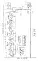
- FIG. 2is a detailed block diagram of the appliance control system, according to a preferred embodiment of the present invention.
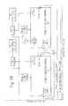
- FIG. 3is a detailed block diagram of a host computer system, according to a preferred embodiment of the present invention.
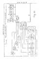
- FIG. 4is a detailed block diagram of an ignition control, according to a preferred embodiment of the present invention.
- FIG. 5is a schematic diagram of a data input interface, according to a preferred embodiment of the present invention.
- the present inventionis contemplated for use with other appliances, including those which generate heat using electricity, a heat pump, oil and the like.
- the gas-fired heating appliancemay use a variety of suitable ignition systems, including standing pilot ignition, spark ignition and hot surface ignition.
- hot water heatergenerally refers to a water heating device for heating potable water
- the term “boiler”generally refers to a water heating device for heating process water (e.g., water for industrial and space heating applications).
- the terms “hot water heater” and “boiler”will be used interchangeably to refer to a water heating device.
- FIG. 1shows a block diagram of a water heating system 2 .
- Water heating system 2is generally comprised of a boiler 10 , a tank 20 , and a controller 30 which includes a host computer HC and a plurality of ignition controls IC 1 , IC 2 , and IC 3 .
- Boiler 10includes a heat exchanger and a plurality of burner chambers BC 1 , BC 2 and BC 3 . Each burner chamber houses a burner B 1 , B 2 , B 3 which is respectively controlled by ignition controls IC 1 , IC 2 and IC 3 .
- Tank 20Water heated by boiler 10 is stored in tank 20 , in accordance with one embodiment of the present invention.
- tank 20provides a hot water supply.
- a boiler inlet temperature probe 32located near the inlet 12 of the boiler heat exchanger
- a boiler outlet temperature probe 34located near the outlet 14 of the boiler heat exchanger
- a remote or tank temperature probe 22provide temperature data to host computer HC for controlling ignition controls IC 1 , IC 2 and IC 3 .
- Ignition controls IC 1 , IC 2 and IC 3are preferably daisy-chained to each other, and share a communications bus, which acts as a communications medium.
- tank 20may not be used (e.g., a space heating application).
- tank temperature probe 22is located at a suitable remote location. Controller 30 , and operation thereof, will be described in further detail below.
- controller 30there is shown a detailed block diagram of controller 30 , according to a preferred embodiment of the present invention. It should be appreciated that while the illustrated embodiment shows a water heating system having three burners, the present invention is applicable to water heating systems having any number of burners.
- Controller 30is generally comprised of host computer HC and ignition controls IC 1 , IC 2 and IC 3 , which are in communication with host computer HC.
- Host computer HCis responsible for such items as sequencing the stages of the boiler, limit switch sensing, high limit safety circuit, inlet, outlet and tank temperature sensing, and remote thermostat.
- Host computer HCoutputs control such items as an alarm, a power vent, a circulation pump, IRI gas valves and power for a low water cut-off device.
- ignition controls IC 1 , IC 2 and IC 3are preferred heating control units. In this regard, where heating is provided by an electric heating element, heating control units suitable for an electric heating element are utilized.
- Host computer HCis shown in greater detail in FIG. 3 .
- host computer HCis generally comprised of a microcontroller 40 , analog multiplexer (MUX) 36 , an optional realtime clock 38 , a data input interface 42 , a power supply 60 , and a data output interface 62 , a first communication interface 82 , a second communication interface 84 , and a display unit 90 .
- Host computer HCfurther comprises a configuration switch 44 , limit switches 46 , opto-isolator circuit 50 , and user input selector switches 48 , which communicate with microcontroller 40 via data input interface 42 .
- host computer HCincludes a relay driver 64 and output relays 66 .
- Relay driver 64is in communication with data output interface 62 .
- microcontroller 40takes the form of a processor, such as an ST62T30 or ST6225B processor from SGS Thompson. It should be understood that other types of microprocessors or discrete processing circuits can be substituted for microcontroller 40 , including processors with significantly greater processing power. Since a preferred embodiment of the present invention divides host computer tasks and ignition control tasks between a plurality of processors, each processor used can be relatively simple and inexpensive.
- Microcontroller 40controls multiplexer 36 to selectively output an analog signal from one of: inlet probe 32 , outlet probe 34 and tank probe 22 .
- the output analog signalis converted to a digital value using an A/D converter internal to microcontroller 40 .
- Inlet probe 32provides a signal indicative of the water temperature at the inlet of boiler 10
- outlet probe 34provides a signal indicative of the water temperature at the outlet of boiler 10
- remote or tank probe 22provides a signal indicative of the temperature of the water stored in tank 20 .
- the probes 32 , 34 and 22include a thermistor (e.g., 10 K ⁇ @ 25° C.) located in an immersion probe housing.
- a power supply circuit 60provides an appropriate supply voltage to microcontroller 40 .
- First communication interface 82provides I/O for communication between microcontroller 40 and the ignition controls IC 1 , IC 2 and IC 3 .
- first communication interface 82preferably takes the form of a serial I/O port, such as an RS-485 compatible interface (which operates in a half-duplex manner), an RS-232 compatible interface, or an RS-422 compatible interface.
- Microcontroller 40“talks” to each ignition control by addressing each one individually. In this regard, each ignition control has a unique address. It should be appreciated that in accordance with a preferred embodiment, host computer HC will “lockout” controller 30 in the event that communication is lost with any ignition control IC 1 , IC 2 and IC 3 .
- a “lockout” of controller 30results in removal of power from the gas valve relays associated with the IRI gas valve (IGV 1 and IGV 2 ), as well as the gas valve relays associated with the gas valves of each burner stage (i.e., GV 1 , GV 2 , and GV 3 ).
- a “lockout”requires a reset action by an operator, such as activation of an ENTER/RESET button.
- Second communication interface 84provides I/O communication between microcontroller 40 and an optional remote computer 4 , a modem, or other device.
- Remote computer 4can be used to monitor operations or reprogram microcontroller 40 .
- second communication interface 84takes the form of a serial I/O port, such as an RS-232 compatible interface, an RS-485 compatible interface, or an RS-422 compatible interface.
- remote computer 4may be a computer that communicates with microcontroller 40 via a computer network, such as the Internet.
- first and second communication interfaces 82 , 84share the UART (Universal Asynchronous Receiver Transmitter) of microcontroller 40 .
- first communication interface 82is given higher priority in using the UART so that critical communications between host computer HC and the ignition controls are not interrupted.
- a plurality of switchesare input to microcontroller 40 , including configuration switch 44 , limit switches 46 , and user input selector switches 48 .
- Configuration switch 44 and user input selector switchesare directly input to data input interface 42
- limit switchesare input to data input interface 42 via opto-isolator circuit 50 .
- Configuration switch 44preferably takes the form of a dip switch having a plurality of inputs.
- the dip switches of configuration switch 44are set to select system parameters, such as the number of burner stages, the number of trials for ignition, whether signals generated by inlet probe 32 or tank probe 22 are used to give the call for heat, whether an external thermostat is connected, a selected maximum setpoint temperature for the boiler outlet before shutdown of controller 30 is initiated, a selected maximum setpoint temperature, and whether display unit 90 displays temperature values in degrees Fahrenheit or Celsius. It should be appreciated that in an alternative embodiment, jumpers could be used to replace the dip switches.
- Limit switches 46include a high limit switch, a low water cutoff switch (LWCO), a circulation pump flow switch, air pressure switches associated with each burner, a power vent switch, a blocked flue switch, a low gas switch, a high gas switch associated with each burner, and an IRI (Industrial Risk Insurers) gas valve switch.
- Limit switches 46form a limit string, as well known to those skilled in the art, and are also connected to fault isolation circuitry (described below). In this regard, a fault occurring on any single limit switch is identified and reported by host computer HC for field diagnostic purposes. Accordingly, the limit switches are connected to fault isolation circuitry in parallel rather than series, as will be described in detail below.
- a limit stringThe intent of a limit string is to provide a means of interrupting power to the main gas valve (or alternatively other heating element, such as electric heating coil and the like) in the event of an unsafe operating condition. Accordingly, the limit string requires that a series of conditions be true (evidenced by closed limit switches) before a voltage (e.g., 24 VAC) is applied to open IRI gas valves IGV 1 and IGV 2 . Accordingly, the limit string provides a safety link for applying 24 VAC or 120 VAC to: (a) the IRI gas valve contactor which opens IRI gas valves IGV 1 and IGV 2 , and (b) the gas valve relays which open gas valves GV 1 , GV 2 and GV 3 associated with each stage burner. It should be understood that IRI gas valves IGV 1 and IGV 2 act as redundant main gas valves, and thus control the flow of gas to gas valves GV 1 , GV 2 and GV 3 , associated with each stage burner.
- a typical limit stringincludes such items as (including but not limited to): a fuse; an ECO (Energy Cut-Out) relay switch; a circulation pump flow switch; a blocked flue switch; an IRI gas valve relay switch; burner gas valve relay switches; a blower pressure switch a low gas pressure switch, a high gas pressure switch and a blocked blower inlet switch, as well as other switches responsive to various operating conditions.
- ECOElectronicgy Cut-Out
- a typical limit stringincludes such items as (including but not limited to): a fuse; an ECO (Energy Cut-Out) relay switch; a circulation pump flow switch; a blocked flue switch; an IRI gas valve relay switch; burner gas valve relay switches; a blower pressure switch a low gas pressure switch, a high gas pressure switch and a blocked blower inlet switch, as well as other switches responsive to various operating conditions.
- Opto-isolator circuit 50includes a contact conditioning circuit, and opto-isolators.
- the opto-isolatorslevel shift the limit switch inputs (e.g., from 24 VAC to 5 VDC), provide noise isolation, and extend the sample time for detecting the status of the limit switches.
- the high limit switchincludes a high limit thermostat that resides in an immersion probe located at the outlet of boiler 10 .
- the high limit thermostatis calibrated to open at a predetermined “high-limit” temperature (e.g., 118° C.).
- a predetermined “high-limit” temperaturee.g., 118° C.
- bimetallic switchestypically have a temperature resolution of approximately +/ ⁇ 3° C.
- the high limit thermostattakes the form of a bimetallic switch.
- the bi-metallic switchopens in response to sensing a temperature which exceeds its rated temperature (i.e., high-limit temperature).
- a 24 VDC supplyis removed from a coil of a relay switch, causing the relay switch to open. Consequently, controller 30 enters a lockout condition.
- the low water cutoff switchindicates whether the water level in the manifold of the boiler heat exchanger is below a predetermined level.
- the state of this switchis indicative of whether there is an appropriate volume of water in the manifold of the heat exchanger.
- the low water cutoff switchis located in close proximity to boiler outlet temperature probe 34 .
- the circulation pump flow switchis used to verify that there is water flow inside the heat exchanger of boiler 10 . Accordingly, the circulation pump flow switch is located at boiler outlet 14 to detect the flow of water when the circulation pump has been activated.
- the power vent switchproves that a power vent associated with the flue has been activated. It should be understood that the power vent assists in expelling combustion gases through the flue.
- Each air pressure switchis used to verify that the combustion blower is generating pressure in the respective burner chamber, when the combustion blower is activated. Accordingly, the air pressure switches respond to the pressure in respective burner chambers.
- the blocked flue switchis a pressure switch which responds to the pressure in the flue. Accordingly, the blocked flue switch will open in response to a blocked flue.
- the low gas pressure switchresponds to the pressure of the gas on the line side of gas valves GV 1 , GV 2 , and GV 3 (or alternatively, the line side of IRI gas valves IGV 1 and IGV 2 ), while each of the high gas pressure switches respond to the pressure of the gas on the burner side of the respective burner gas valve.
- the low and high gas pressure switchesare respectively adapted to respond to low and high gas pressure thresholds. Accordingly, the low gas pressure switch opens in response to a low gas pressure in the gas line, while the high gas pressure switches open in response to a high gas pressure in the gas line.
- the IRI gas valve switchindicates whether the IRI gas valves are functioning (i.e., proof of closure switch).
- an external thermostat 24 inputis optionally input to microcontroller 40 via opto-isolator circuit 50 and data input interface 42 .
- external thermostat 24takes the form of a bi-mettalic device wherein a temperature drop below a predetermined threshold closes the contacts.
- the external thermostatis typically used in a space heating application to provide an indication of ambient temperature.
- switches 48are used by the operator to select parameters to adjust or display, adjusting a user programmable parameter, saving newly entered parameters, reset the control when a controller “lockout” occurs, and the like.
- switches 48take the form of a plurality of momentary contact pushbutton switches, including an ADJUST, a SELECT, and an ENTER/RESET pushbutton switches.
- Data input interface 42provides an interface for inputting data to microcontroller 40 (FIG. 5 ).
- data input interface 42includes a plurality of 8-bit parallel-to-serial shift registers S 1 , S 2 and S 3 .
- the parallel inputs to the shift registerinclude output signals from configuration switch 44 , output signals from opto-isolation circuit 50 , which indicates the state of each of the limit switches 46 , and output signals from user input selector switches 48 . It should be understood that the number of shift registers may vary depending upon the number of inputs and the size of the shift registers.
- limit switches 46are connected to fault isolation circuitry, so that a fault occurring on any single limit switch can be identified and reported by host computer HC for field diagnostic purposes.
- data input interface 42 and microcontroller 40provide fault isolation circuitry.
- shift registers S, S 2 , and S 3clock the state of limit switches 46 into microcontroller 40 .
- the limit switchescan be input in parallel to the microcontroller, where sufficient inputs are available.
- the shift registers of the preferred embodimentare used to minimize the need for numerous data inputs in microcontroller 40 .
- Microcontroller 40is programmed to continuously scan the state of limit switches 46 to determine whether they are in the proper state during all phases of an ignition control cycle.
- a 3-byte wordis input to microcontroller 40 .
- the status of each of the bitsis evaluated (e.g., by comparison to values stored in a look-up table indicative of various operating states) to determine whether the status of the associated component is appropriate for the current operating state (e.g., call-for-heat/pre-circulate, pre-purge, warm-up, trial for ignition, heating, post purge, and post circulate).
- the current operating statee.g., call-for-heat/pre-circulate, pre-purge, warm-up, trial for ignition, heating, post purge, and post circulate.
- microcontroller 40allows for identification of the specific component which is the source of the malfunction. By reporting the identified malfunctioning component to the operator using display unit 90 , service technicians can quickly make repairs.
- Realtime clock 38provides a time signal to microcontroller 40 so that microcontroller can be conveniently programmed to operate water heating system 2 according to a timer schedule.
- controller 30could be set to operate in different modes during evening or weekend hours, or during holiday and vacation periods.
- Display unit 90may take numerous suitable forms, including LED, LCD and CRT displays.
- display unit 90includes a plurality of multi-colored LEDs, including a four digit, seven segment LED display that indicates inlet temperature, outlet temperature or tank temperatures, setpoint temperatures and setpoint differentials, error codes, cycle counts, post-circulation pump time, and last error.
- Display unit 90further includes a plurality of discrete LEDs which illuminate to communicate information identifying stages, providing diagnostics, and acting as system indicators. More specifically, the “diagnostic” LEDs may indicate such items as ECO failure, flame failure, igniter failure, insufficient air, blocked flue, probe failure, circulate failure, gas valve failure, high gas failure, low gas failure, low water cut-off, and power vent failure.
- LEDsare provided to identify the display of such items as inlet water temperature, outlet water temperature, stage setpoint temperature, stage setpoint differential, and standby. It should be appreciated that the use of LEDs as described above is merely for illustrating a preferred embodiment, and is not intended to limit the type of suitable display units.
- Microcontroller 40controls output relays 66 by outputting data via data output interface 62 and relay driver 64 .
- data output interfacetakes the form of a serial-to-parallel shift register. As data bits are latched in the shift register outputs, relays controlling such items as an alarm, a power vent, a circulation pump, and IRI gas valves IGV 1 , IGV 2 , are turned on and off at the appropriate times.
- ignition control IC 1will be described in detail. It will be appreciated that the other ignition controls IC 2 , IC 3 (and any necessary additional ignition controls) are similarly configured. In general, ignition controls are responsible for controlling associated combustion blowers, hot surface igniters (HSI), and gas valves. Moreover, each ignition control is capable of monitoring gas valve power, gas valve relay, flame sense and igniter current.
- HSEhot surface igniters
- Ignition control IC 1is generally comprised of a microcontroller 110 , a communication interface 182 , gas valve relays (burner and redundant) 130 , a gas valve power sensor circuit 132 , a gas valve relay sensor circuit 134 , an igniter current sensor circuit 120 , a flame sensor circuit 122 , and power supplies 160 .
- ignition controlsmay be operated separately and independently from host computer HC.
- ignition control IC 1also includes an ECO/first temperature probe 112 , a second temperature probe 114 , a ECO switch sensor circuit 116 , a pressure switch sensor 142 , a remote thermostat/IRI proving switch 144 and a flow/pressure/tach signal 146 .
- Tach signal 146provides feedback from a variable speed motor used in connection with the combustion blower.
- microcontroller 110takes the form of a processor, such as an ST62T30 or ST6225B processor from SGS Thompson. It should be understood that other types of microprocessors or discrete processing circuits can be substituted for microcontroller 110 , including processors with significantly greater processing power. As mentioned above, since a preferred embodiment of the present invention divides host computer tasks and ignition control tasks between a plurality of processors, each processor used can be relatively simple and inexpensive.
- Communication interface 182provides I/O for communication between microcontroller 110 and host computer HC.
- communication interface 182takes the form of a serial I/O port, such as an RS-485 compatible interface (which operates in a half-duplex manner), an RS-232 compatible interface, or an RS-422 compatible interface.
- each ignition controlhas a unique address. Accordingly, microcontroller 110 will take control of the communications bus and transmit when instructed by host computer HC. It should be understood that in a preferred embodiment, the ignition controls IC 1 , IC 2 and IC 3 are daisy-chained.
- Gas valve power sensor circuit 132senses whether power (e.g., 24 VAC) is being provided to the relay contacts of the respective gas valve GV 1 .
- powere.g., 24 VAC
- poweris sensed through a resistor. Accordingly, an appropriate ‘digital’ voltage is input to microcontroller 110 . If no power is sensed, then microcontroller 110 will cause a “lockout” of controller 30 . As indicated above, “lockout” of controller 30 results in removal of power from the gas valve relays associated with the IRI gas valves (IGV 1 and IGV 2 ), as well as the gas valve relays associated with the gas valves of each burner stage (i.e., gas valves GV 1 , GV 2 , and GV 3 ).
- Gas Valve GV 1is preferably powered by a pair of relays.
- the first relayswitches the gas valve OPEN/CLOSED, while the second relay merely provides redundancy.
- Gas valve relay sensor circuit 134senses the state of the first relay, and provides status information to microcontroller 110 .
- activation of the first relayis sensed through a resistor. Therefore, an appropriate ‘digital’ voltage is input to microcontroller 110 .
- microcontroller 110can verify and monitor the state of the first relay. Accordingly, microcontroller 110 may be programmed to “lockout” controller 30 if the relay contact in not in the proper position in a particular control state.
- a 120 VAC or 24 VAC igniteris energized by hot surface igniter relay 170 . It should be appreciated that the present invention is also suitably used in connection with other types of ignition systems, including standing pilot and spark ignition systems.
- Igniter current sensor circuit 120proves the presence of a “hot” surface igniter by validating the igniter current flowing therethrough. If inadequate igniter current is sensed prior to opening the respective gas valve GV 1 , microcontroller 110 will not allow the associated gas valve relays 130 (including burner and redundant relays) to energize. Consequently, gas valve GV 1 will not open. This prevents the buildup of gas which could cause an explosion when ignited by the igniter.
- microcontroller 110is programmed to attempt a predetermined number of trials (e.g., 1 or 3 trials) for sufficient igniter current. If sufficient current is not sensed during one of the trials, controller 30 will “lockout.” Controller 30 will also “lockout” if igniter current is sensed during a control state when there should be no igniter current.
- igniter current sensor circuit 120preferably uses a current sense transformer.
- igniter currentpasses through the transformer primary winding.
- Current induced into the transformer secondary windinggenerates a voltage across a burden resister, which is amplified and scaled (e.g., 1V/Amp) by an op-amp circuit.
- This scaled output voltageis input to microcontroller 110 , which performs an analog-to-digital conversion. If the scaled output voltage is less than a predetermined value (e.g., 2.7 volts), microcontroller 110 determines that there is inadequate igniter current.
- a predetermined valuee.g., 2.7 volts
- microcontroller 110determines that there is inadequate igniter current.
- the digitized scaled output voltagemay also be displayed to the operator on display unit 90 for use as a diagnostic tool and igniter performance indicator.
- Flame sensor circuit 122receives input from a flame sense rod, which is a probe located in the gas flame of the respective burner.
- the flame sense rodpreferably detects the presence of a flame using a well known technique referred to as “flame rectification.”
- a capacitoris charged by an op-amp circuit during the first half of a charge/discharge cycle, and is discharged by flame rectification during the second half of the charge/discharge cycle.
- the average current resulting from this charge/discharge cycleis what is measured as the flame current by flame sensor circuit 122 .
- Microcontroller 110is programmed to constantly monitor the flame current.
- microcontroller 110determines that there is insufficient flame current during a “heat mode,” the ignition control IC 1 will begin another attempt to light gas until a predetermined number of ignition trials (e.g., 1 or 3 trials) are completed. Moreover, ignition control IC 1 will “lockout” if adequate flame current has not been sensed, or if flame current is sensed during a control state when flame current should not exist.
- a predetermined number of ignition trialse.g., 1 or 3 trials
- power supplies 160includes three regulated power supplies, which respectively provide +24 VDC, +15 VDC and +5 VDC.
- Microcontroller 1 10controls the state of combustion blower CB 1 through a combustion blower relay 172 and controls the state of the recirculation pump through a recirculation pump relay 174 .
- combustion blower CB 1operates at two speeds, namely low speed and high speed.
- Microcontroller 110or microcontroller 40 ) controls the operating speed. At ignition (i.e., while the respective hot surface igniter is activated), combustion blower CB 1 is operated at the low speed. At other times, combustion blower CB 1 is operated at high speed. Therefore, combustion blower CB 1 shifts to low speed at ignition, and once ignition is completed (e.g., when an appropriate flame is sensed), combustion blower CB 1 resumes operation at high speed. The foregoing operation facilitates ignition under lean mixture conditions.
- microcontroller 110controls operation of combustion blower CB 1 using a variable output signal (e.g., a pulse width modulation (PWM) output signal).
- a variable output signale.g., a pulse width modulation (PWM) output signal
- the variable output signalprovides adaptive control of combustion blower CB 1 , which may take the form of a variable-speed combustion blower.
- microcontroller 110(or microcontroller 40 ) may provide a variable output signal for adaptive control of other items such as a variable-speed circulation pump, and/or variable gas valve. These variable output signals provide a range of values, rather than just an ON and OFF value.
- the microcontrollersmay receive inputs from pressure and/or flow transducers, which provide feedback information from the combustion blower, pump and/or gas valve. This feedback information is used by the microcontrollers to modulate the output control signals.
- the ignition controlsmay be used separately and independently from host computer HC. Accordingly, an ECO probe/first probe 112 may be used to provide temperature information indicative of water temperature at the inlet to a heating chamber, while second probe 114 may be used to provide temperature information indicative of water temperature at the outlet of a heating chamber. Probes 112 and 114 preferably take the form of a thermistor.
- the ECO probeis located at the first probe to sense a high-limit temperature.
- ECO switch sensor circuit 116evaluates the data received from the ECO probe, and operates independently of microcontroller 110 .
- ECO switch sensor circuit 116includes circuitry for determining whether the temperature has exceeded a “high limit” temperature (e.g., 250 degrees F.), and whether there is an open ECO probe (fault condition). When this condition is sensed, ECO switch sensor circuit 116 causes all gas valve relay switches to open, which in turn closes gas valves IGV 1 , IGV 2 , GV 1 , GV 2 , and GV 3 .
- ECO switch sensor circuit 116also provides a signal to microcontroller 110 indicative of the state of the ECO probe.
- Pressure switch sensor 142provides a signal to microcontroller 110 indicative of the state of a blower pressure switch.
- the blower pressure switchis used to verify that combustion blower CB 1 is generating pressure in the respective burner chamber, when combustion blower CB 1 is activated. Accordingly, the pressure switch responds to the pressure in the burner chamber. The blower pressure switch is closed when the pressure reaches a predetermined level.
- Remote thermostat 144is optionally connected with microcontroller 110 .
- microcontroller 110looks for an external thermostat signal which “overrides” (“AND” function) the local setpoint temperature provided by host computer HC.
- external thermostat 144takes the form of a bi-mettalic device wherein a temperature drop below a predetermined threshold closes the contacts.
- the external thermostatis typically used in a space heating application to provide an indication of ambient temperature.
- each ignition control IC 1 , IC 2 , IC 3may have different components, since such elements as combustion blower and hot surface igniter (HSI) may not be needed for each burner stage.
- HSIhot surface igniter
- the flame generated in the first stage burnercan be utilized to ignite the flame in subsequent stage burners (“flame carryover”). Therefore, an HSI is needed only for the first stage burner.
Landscapes
- Engineering & Computer Science (AREA)
- Chemical & Material Sciences (AREA)
- Combustion & Propulsion (AREA)
- Mechanical Engineering (AREA)
- General Engineering & Computer Science (AREA)
- Regulation And Control Of Combustion (AREA)
Abstract
Description
| ERROR | |||
| FAULT CONDITION | CODE | ||
| Communication Fault - | 001 | ||
| Communication Fault - | 002 | ||
| Communication Fault - | 003 | ||
| ECO/High Limit | 010 | ||
| No Gas Valve Power Sensed - | 011 | ||
| No Gas Valve Power Sensed - | 012 | ||
| No Gas Valve Power Sensed - | 013 | ||
| LWCO | 020 | ||
| Circulate Fault (Flow Switch) | 030 | ||
| Insufficient Air (Air Pressure Switch) - | 041 | ||
| Insufficient Air (Air Pressure Switch) - | 042 | ||
| Insufficient Air (Air Pressure Switch) - | 043 | ||
| Blocked Flue | 060 | ||
| Power Vent | 070 | ||
| Igniter Failure - | 081 | ||
| Igniter Failure - | 082 | ||
| Igniter Failure - | 083 | ||
| Low Gas Failure | 090 | ||
| High-Gas Failure - | 101 | ||
| High-Gas Failure - | 102 | ||
| High-Gas Failure - | 103 | ||
| Gas Valve Relay Failure - | 111 | ||
| Gas Valve Relay Failure - | 112 | ||
| Gas Valve Relay Failure - | 113 | ||
| Flame Failure - | 121 | ||
| Flame Failure - | 122 | ||
| Flame Failure - | 123 | ||
| Probe Faults - Outlet Probe | 131 | ||
| Probe Faults - | 132 | ||
| Probe Faults - Remote/Tank Probe | 133 | ||
| IRI Gas Valve Failure | 140 | ||
| Microcontroller Fault | 210 | ||
Claims (33)
Priority Applications (3)
| Application Number | Priority Date | Filing Date | Title |
|---|---|---|---|
| US09/589,586US6728600B1 (en) | 2000-06-08 | 2000-06-08 | Distributed appliance control system having fault isolation |
| AU2001275430AAU2001275430A1 (en) | 2000-06-08 | 2001-06-08 | Distributed appliance control system having fault isolation |
| PCT/US2001/018684WO2001094847A2 (en) | 2000-06-08 | 2001-06-08 | Distributed appliance control system having fault isolation |
Applications Claiming Priority (1)
| Application Number | Priority Date | Filing Date | Title |
|---|---|---|---|
| US09/589,586US6728600B1 (en) | 2000-06-08 | 2000-06-08 | Distributed appliance control system having fault isolation |
Publications (1)
| Publication Number | Publication Date |
|---|---|
| US6728600B1true US6728600B1 (en) | 2004-04-27 |
Family
ID=24358626
Family Applications (1)
| Application Number | Title | Priority Date | Filing Date |
|---|---|---|---|
| US09/589,586Expired - LifetimeUS6728600B1 (en) | 2000-06-08 | 2000-06-08 | Distributed appliance control system having fault isolation |
Country Status (3)
| Country | Link |
|---|---|
| US (1) | US6728600B1 (en) |
| AU (1) | AU2001275430A1 (en) |
| WO (1) | WO2001094847A2 (en) |
Cited By (54)
| Publication number | Priority date | Publication date | Assignee | Title |
|---|---|---|---|---|
| US20040155809A1 (en)* | 2003-02-06 | 2004-08-12 | Eyer Mark Kenneth | Infrared remote control command network pass-through |
| US20050062032A1 (en)* | 2003-09-20 | 2005-03-24 | Agilent Technologies, Inc. | Semiconductor device |
| US7020543B1 (en)* | 2004-10-12 | 2006-03-28 | Emerson Electric, Co. | Controller for fuel fired heating appliance |
| US20070068511A1 (en)* | 2005-09-28 | 2007-03-29 | Hearth & Home Technologies | Gas fireplace monitoring and control system |
| US20070125366A1 (en)* | 2005-12-05 | 2007-06-07 | Moreland Larry K | Blower timing system for a gas fireplace |
| US20080023461A1 (en)* | 2006-07-17 | 2008-01-31 | Honeywell International Inc. | Appliance control with ground reference compensation |
| US20080083404A1 (en)* | 2006-10-06 | 2008-04-10 | Seacombe Technologies Australia Pty Ltd. | Space Heater with Microprocessor Control |
| US20090061367A1 (en)* | 2007-08-28 | 2009-03-05 | Andrew Robert Caves | Appliance having a safety string |
| US20090056649A1 (en)* | 2007-08-31 | 2009-03-05 | Mackenzie Bruce G | Boiler Protection Apparatus and Method |
| US20090084329A1 (en)* | 2006-04-19 | 2009-04-02 | Daikin Industries, Ltd. | Malfunction detection device for hot water supplier |
| US7784705B2 (en) | 2006-02-27 | 2010-08-31 | Honeywell International Inc. | Controller with dynamic temperature compensation |
| US7818095B2 (en) | 2007-02-06 | 2010-10-19 | Rheem Manufacturing Company | Water heater monitor/diagnostic display apparatus |
| US20110145772A1 (en)* | 2009-05-14 | 2011-06-16 | Pikus Fedor G | Modular Platform For Integrated Circuit Design Analysis And Verification |
| US8069013B2 (en) | 2007-02-06 | 2011-11-29 | Rheem Manufacturing Company | Water heater monitor/diagnostic display apparatus |
| US20120024240A1 (en)* | 2010-07-27 | 2012-02-02 | Bryan James Beckley | System and method for regulating temperature in a hot water heater |
| US20120125268A1 (en)* | 2010-11-24 | 2012-05-24 | Grand Mate Co., Ltd. | Direct vent/power vent water heater and method of testing for safety thereof |
| EP2604924A3 (en)* | 2011-12-15 | 2013-07-10 | Honeywell International Inc. | Gas valve with communication link |
| US8839815B2 (en) | 2011-12-15 | 2014-09-23 | Honeywell International Inc. | Gas valve with electronic cycle counter |
| US8899264B2 (en) | 2011-12-15 | 2014-12-02 | Honeywell International Inc. | Gas valve with electronic proof of closure system |
| US8905063B2 (en) | 2011-12-15 | 2014-12-09 | Honeywell International Inc. | Gas valve with fuel rate monitor |
| US8949066B2 (en) | 2007-12-04 | 2015-02-03 | Honeywell International Inc. | System for determining ambient temperature |
| US8947242B2 (en) | 2011-12-15 | 2015-02-03 | Honeywell International Inc. | Gas valve with valve leakage test |
| US9074770B2 (en) | 2011-12-15 | 2015-07-07 | Honeywell International Inc. | Gas valve with electronic valve proving system |
| US9086068B2 (en) | 2011-09-16 | 2015-07-21 | Grand Mate Co., Ltd. | Method of detecting safety of water heater |
| WO2015143527A1 (en)* | 2014-03-26 | 2015-10-01 | Martino Contractors Ltd. | A monitor for a natural gas-fired appliance |
| US9234661B2 (en) | 2012-09-15 | 2016-01-12 | Honeywell International Inc. | Burner control system |
| US9335769B2 (en) | 2007-12-04 | 2016-05-10 | Honeywell International Inc. | System for determining ambient temperature |
| US20170030623A1 (en)* | 2015-07-31 | 2017-02-02 | Trane International Inc. | Multi-stage control for electromechanical heating, ventilation, and air conditioning (hvac) unit |
| WO2017049124A1 (en)* | 2015-09-16 | 2017-03-23 | Profire Energy, Inc. | Distributed networking system and method |
| US9645584B2 (en) | 2014-09-17 | 2017-05-09 | Honeywell International Inc. | Gas valve with electronic health monitoring |
| US9683674B2 (en) | 2013-10-29 | 2017-06-20 | Honeywell Technologies Sarl | Regulating device |
| US9797619B2 (en) | 2013-03-15 | 2017-10-24 | Honeywell International Inc. | Temperature compensation system for an electronic device |
| US9835265B2 (en) | 2011-12-15 | 2017-12-05 | Honeywell International Inc. | Valve with actuator diagnostics |
| US9841122B2 (en) | 2014-09-09 | 2017-12-12 | Honeywell International Inc. | Gas valve with electronic valve proving system |
| US9846440B2 (en) | 2011-12-15 | 2017-12-19 | Honeywell International Inc. | Valve controller configured to estimate fuel comsumption |
| US9851103B2 (en) | 2011-12-15 | 2017-12-26 | Honeywell International Inc. | Gas valve with overpressure diagnostics |
| US20180038615A1 (en)* | 2016-06-10 | 2018-02-08 | Pratik N. SHAH | Field configurable low water cut-offs |
| US9995486B2 (en) | 2011-12-15 | 2018-06-12 | Honeywell International Inc. | Gas valve with high/low gas pressure detection |
| US10024439B2 (en) | 2013-12-16 | 2018-07-17 | Honeywell International Inc. | Valve over-travel mechanism |
| US20180306445A1 (en)* | 2017-04-22 | 2018-10-25 | Emerson Electric Co. | Igniter failure detection assemblies for furnaces, and corresponding methods of detecting igniter failure |
| US10174969B2 (en) | 2011-08-12 | 2019-01-08 | Lennox Industries Inc. | Furnace, a high fire ignition method for starting a furnace and a furnace controller configured for the same |
| US10209751B2 (en) | 2012-02-14 | 2019-02-19 | Emerson Electric Co. | Relay switch control and related methods |
| US10422531B2 (en) | 2012-09-15 | 2019-09-24 | Honeywell International Inc. | System and approach for controlling a combustion chamber |
| US10432754B2 (en) | 2015-09-16 | 2019-10-01 | Profire Energy, Inc | Safety networking protocol and method |
| US10503181B2 (en) | 2016-01-13 | 2019-12-10 | Honeywell International Inc. | Pressure regulator |
| US10508807B2 (en)* | 2014-05-02 | 2019-12-17 | Air Products And Chemicals, Inc. | Remote burner monitoring system and method |
| US10514683B2 (en) | 2015-09-16 | 2019-12-24 | Profire Energy, Inc. | Distributed networking system and method to implement a safety state environment |
| US10564062B2 (en) | 2016-10-19 | 2020-02-18 | Honeywell International Inc. | Human-machine interface for gas valve |
| US10697815B2 (en) | 2018-06-09 | 2020-06-30 | Honeywell International Inc. | System and methods for mitigating condensation in a sensor module |
| US10976761B2 (en)* | 2017-11-21 | 2021-04-13 | Swagelok Company | Electrical heater for flow control device |
| US11073281B2 (en) | 2017-12-29 | 2021-07-27 | Honeywell International Inc. | Closed-loop programming and control of a combustion appliance |
| US11125439B2 (en) | 2018-03-27 | 2021-09-21 | Scp Holdings, An Assumed Business Name Of Nitride Igniters, Llc | Hot surface igniters for cooktops |
| US11408639B2 (en)* | 2016-02-19 | 2022-08-09 | Lippert Components Manufacturing, Inc. | Tankless water heaters and related methods for recreational vehicles |
| US20220260281A1 (en)* | 2017-12-21 | 2022-08-18 | Rheem Manufacturing Company | Water heater operation monitoring and notification |
Families Citing this family (5)
| Publication number | Priority date | Publication date | Assignee | Title |
|---|---|---|---|---|
| US6536678B2 (en) | 2000-12-15 | 2003-03-25 | Honeywell International Inc. | Boiler control system and method |
| ES2611010T3 (en)* | 2004-03-02 | 2017-05-04 | Riello S.P.A. | Electronic regulation device and electric motor applied to a burner fan |
| US7819334B2 (en) | 2004-03-25 | 2010-10-26 | Honeywell International Inc. | Multi-stage boiler staging and modulation control methods and controllers |
| US8251297B2 (en) | 2004-04-16 | 2012-08-28 | Honeywell International Inc. | Multi-stage boiler system control methods and devices |
| JP6617305B2 (en)* | 2016-01-13 | 2019-12-11 | パナソニック株式会社 | Flow measuring device |
Citations (10)
| Publication number | Priority date | Publication date | Assignee | Title |
|---|---|---|---|---|
| US4444551A (en)* | 1981-08-27 | 1984-04-24 | Emerson Electric Co. | Direct ignition gas burner control system |
| US4518345A (en)* | 1983-02-28 | 1985-05-21 | Emerson Electric Co. | Direct ignition gas burner control system |
| EP0325356A2 (en) | 1988-01-21 | 1989-07-26 | Honeywell Inc. | Multiple fuel burner control system |
| US4925386A (en)* | 1989-02-27 | 1990-05-15 | Emerson Electric Co. | Fuel burner control system with hot surface ignition |
| US5103078A (en)* | 1990-02-01 | 1992-04-07 | Boykin T Brooks | Programmable hot water heater control method |
| US5549469A (en)* | 1994-02-28 | 1996-08-27 | Eclipse Combustion, Inc. | Multiple burner control system |
| US5629879A (en) | 1993-12-24 | 1997-05-13 | Landis & Gyr Technology Innovation Ag | Control device for the actuation of switchgears according to a time program |
| US5651193A (en) | 1994-02-09 | 1997-07-29 | The Gsi Group, Inc. | Grain dryer and control system therefor |
| EP0931990A2 (en) | 1998-01-23 | 1999-07-28 | Tridelta Industries, Inc. | Appliance control |
| US5951276A (en)* | 1997-05-30 | 1999-09-14 | Jaeschke; James R. | Electrically enhanced hot surface igniter |
Family Cites Families (4)
| Publication number | Priority date | Publication date | Assignee | Title |
|---|---|---|---|---|
| JPH0221123A (en)* | 1988-07-11 | 1990-01-24 | Matsushita Electric Ind Co Ltd | Control device for hot water supply equipment |
| JPH0462301A (en)* | 1990-06-29 | 1992-02-27 | Kurita Water Ind Ltd | Thermal equipment data communication system |
| JP3238902B2 (en)* | 1991-04-22 | 2001-12-17 | 高木産業株式会社 | Water heater failure diagnosis system |
| JP3629901B2 (en)* | 1997-06-24 | 2005-03-16 | 株式会社ノーリツ | Water heater control system controller and water heater system |
- 2000
- 2000-06-08USUS09/589,586patent/US6728600B1/ennot_activeExpired - Lifetime
- 2001
- 2001-06-08AUAU2001275430Apatent/AU2001275430A1/ennot_activeAbandoned
- 2001-06-08WOPCT/US2001/018684patent/WO2001094847A2/enactiveApplication Filing
Patent Citations (12)
| Publication number | Priority date | Publication date | Assignee | Title |
|---|---|---|---|---|
| US4444551A (en)* | 1981-08-27 | 1984-04-24 | Emerson Electric Co. | Direct ignition gas burner control system |
| US4518345A (en)* | 1983-02-28 | 1985-05-21 | Emerson Electric Co. | Direct ignition gas burner control system |
| EP0325356A2 (en) | 1988-01-21 | 1989-07-26 | Honeywell Inc. | Multiple fuel burner control system |
| US4925386A (en)* | 1989-02-27 | 1990-05-15 | Emerson Electric Co. | Fuel burner control system with hot surface ignition |
| US5103078A (en)* | 1990-02-01 | 1992-04-07 | Boykin T Brooks | Programmable hot water heater control method |
| US5629879A (en) | 1993-12-24 | 1997-05-13 | Landis & Gyr Technology Innovation Ag | Control device for the actuation of switchgears according to a time program |
| US5651193A (en) | 1994-02-09 | 1997-07-29 | The Gsi Group, Inc. | Grain dryer and control system therefor |
| US5549469A (en)* | 1994-02-28 | 1996-08-27 | Eclipse Combustion, Inc. | Multiple burner control system |
| US5951276A (en)* | 1997-05-30 | 1999-09-14 | Jaeschke; James R. | Electrically enhanced hot surface igniter |
| EP0931990A2 (en) | 1998-01-23 | 1999-07-28 | Tridelta Industries, Inc. | Appliance control |
| US6059195A (en)* | 1998-01-23 | 2000-05-09 | Tridelta Industries, Inc. | Integrated appliance control system |
| US6129284A (en)* | 1998-01-23 | 2000-10-10 | Tridelta Industries, Inc. | Integrated appliance control system |
Non-Patent Citations (4)
| Title |
|---|
| Abstract of Japanese Patent Application No. JP 02 021123 A, Publication No. 02021123, published Jan. 24, 1990. |
| Abstract of Japanese Patent Application No. JP 04 062301 A, Publication No. 04062301, published Feb. 27, 1992. |
| Abstract of Japanese Patent Application No. JP 11 018169 A, Publication No. 1108169, published on Jan. 22, 1999. |
| Abstract of Japanese Patent Application No. JP 11 134019 A, Publication No. 11134019, published May 21, 1999. |
Cited By (87)
| Publication number | Priority date | Publication date | Assignee | Title |
|---|---|---|---|---|
| US20040155809A1 (en)* | 2003-02-06 | 2004-08-12 | Eyer Mark Kenneth | Infrared remote control command network pass-through |
| US20050062032A1 (en)* | 2003-09-20 | 2005-03-24 | Agilent Technologies, Inc. | Semiconductor device |
| US7020543B1 (en)* | 2004-10-12 | 2006-03-28 | Emerson Electric, Co. | Controller for fuel fired heating appliance |
| US20060080000A1 (en)* | 2004-10-12 | 2006-04-13 | Jaeschke Horst E | Controller for fuel fired heating appliance |
| US20060106498A1 (en)* | 2004-10-12 | 2006-05-18 | Emerson Electric Co. | Controller for fuel fired heating appliance |
| US7191039B2 (en)* | 2004-10-12 | 2007-03-13 | Emerson Electric Co. | Controller for fuel fired heating appliance |
| US20070068511A1 (en)* | 2005-09-28 | 2007-03-29 | Hearth & Home Technologies | Gas fireplace monitoring and control system |
| US20070125366A1 (en)* | 2005-12-05 | 2007-06-07 | Moreland Larry K | Blower timing system for a gas fireplace |
| US7784705B2 (en) | 2006-02-27 | 2010-08-31 | Honeywell International Inc. | Controller with dynamic temperature compensation |
| US8365686B2 (en)* | 2006-04-19 | 2013-02-05 | Daikin Industries, Ltd. | Malfunction detection device for hot water supplier |
| US20090084329A1 (en)* | 2006-04-19 | 2009-04-02 | Daikin Industries, Ltd. | Malfunction detection device for hot water supplier |
| US20080023461A1 (en)* | 2006-07-17 | 2008-01-31 | Honeywell International Inc. | Appliance control with ground reference compensation |
| US7538297B2 (en) | 2006-07-17 | 2009-05-26 | Honeywell International Inc. | Appliance control with ground reference compensation |
| US20080083404A1 (en)* | 2006-10-06 | 2008-04-10 | Seacombe Technologies Australia Pty Ltd. | Space Heater with Microprocessor Control |
| US7818095B2 (en) | 2007-02-06 | 2010-10-19 | Rheem Manufacturing Company | Water heater monitor/diagnostic display apparatus |
| US8069013B2 (en) | 2007-02-06 | 2011-11-29 | Rheem Manufacturing Company | Water heater monitor/diagnostic display apparatus |
| US20090061368A1 (en)* | 2007-08-28 | 2009-03-05 | Andrew Robert Caves | Appliance having load monitoring system |
| US20090061367A1 (en)* | 2007-08-28 | 2009-03-05 | Andrew Robert Caves | Appliance having a safety string |
| US20090056649A1 (en)* | 2007-08-31 | 2009-03-05 | Mackenzie Bruce G | Boiler Protection Apparatus and Method |
| US8008603B2 (en)* | 2007-08-31 | 2011-08-30 | Mackenzie Bruce G | Boiler protection apparatus and method |
| US8954288B2 (en) | 2007-12-04 | 2015-02-10 | Honeywell International Inc. | System for determining ambient temperature |
| US9326323B2 (en) | 2007-12-04 | 2016-04-26 | Honeywell International Inc. | System for determining ambient temperature |
| US10805987B2 (en) | 2007-12-04 | 2020-10-13 | Ademco Inc. | System for determining ambient temperature |
| US9335769B2 (en) | 2007-12-04 | 2016-05-10 | Honeywell International Inc. | System for determining ambient temperature |
| US10222271B2 (en) | 2007-12-04 | 2019-03-05 | Ademco Inc. | System for determining ambient temperature |
| US9345066B2 (en) | 2007-12-04 | 2016-05-17 | Honeywell International Inc. | System for determining ambient temperature |
| US10154541B2 (en) | 2007-12-04 | 2018-12-11 | Honeywell International Inc. | System for determining ambient temperature |
| US8949066B2 (en) | 2007-12-04 | 2015-02-03 | Honeywell International Inc. | System for determining ambient temperature |
| US20110145772A1 (en)* | 2009-05-14 | 2011-06-16 | Pikus Fedor G | Modular Platform For Integrated Circuit Design Analysis And Verification |
| US8538597B2 (en)* | 2010-07-27 | 2013-09-17 | General Electric Company | System and method for regulating temperature in a hot water heater |
| US20120024240A1 (en)* | 2010-07-27 | 2012-02-02 | Bryan James Beckley | System and method for regulating temperature in a hot water heater |
| US9249988B2 (en)* | 2010-11-24 | 2016-02-02 | Grand Mate Co., Ted. | Direct vent/power vent water heater and method of testing for safety thereof |
| US20120125268A1 (en)* | 2010-11-24 | 2012-05-24 | Grand Mate Co., Ltd. | Direct vent/power vent water heater and method of testing for safety thereof |
| US10174969B2 (en) | 2011-08-12 | 2019-01-08 | Lennox Industries Inc. | Furnace, a high fire ignition method for starting a furnace and a furnace controller configured for the same |
| US9086068B2 (en) | 2011-09-16 | 2015-07-21 | Grand Mate Co., Ltd. | Method of detecting safety of water heater |
| EP2604924B1 (en) | 2011-12-15 | 2015-05-06 | Honeywell International Inc. | Gas valve with communication link |
| US8899264B2 (en) | 2011-12-15 | 2014-12-02 | Honeywell International Inc. | Gas valve with electronic proof of closure system |
| US10697632B2 (en) | 2011-12-15 | 2020-06-30 | Honeywell International Inc. | Gas valve with communication link |
| EP2604924A3 (en)* | 2011-12-15 | 2013-07-10 | Honeywell International Inc. | Gas valve with communication link |
| US9074770B2 (en) | 2011-12-15 | 2015-07-07 | Honeywell International Inc. | Gas valve with electronic valve proving system |
| US8839815B2 (en) | 2011-12-15 | 2014-09-23 | Honeywell International Inc. | Gas valve with electronic cycle counter |
| US9557059B2 (en) | 2011-12-15 | 2017-01-31 | Honeywell International Inc | Gas valve with communication link |
| US8947242B2 (en) | 2011-12-15 | 2015-02-03 | Honeywell International Inc. | Gas valve with valve leakage test |
| US8905063B2 (en) | 2011-12-15 | 2014-12-09 | Honeywell International Inc. | Gas valve with fuel rate monitor |
| US10851993B2 (en) | 2011-12-15 | 2020-12-01 | Honeywell International Inc. | Gas valve with overpressure diagnostics |
| US9995486B2 (en) | 2011-12-15 | 2018-06-12 | Honeywell International Inc. | Gas valve with high/low gas pressure detection |
| US9851103B2 (en) | 2011-12-15 | 2017-12-26 | Honeywell International Inc. | Gas valve with overpressure diagnostics |
| US9846440B2 (en) | 2011-12-15 | 2017-12-19 | Honeywell International Inc. | Valve controller configured to estimate fuel comsumption |
| US9835265B2 (en) | 2011-12-15 | 2017-12-05 | Honeywell International Inc. | Valve with actuator diagnostics |
| US10209751B2 (en) | 2012-02-14 | 2019-02-19 | Emerson Electric Co. | Relay switch control and related methods |
| US9234661B2 (en) | 2012-09-15 | 2016-01-12 | Honeywell International Inc. | Burner control system |
| US10422531B2 (en) | 2012-09-15 | 2019-09-24 | Honeywell International Inc. | System and approach for controlling a combustion chamber |
| US9657946B2 (en) | 2012-09-15 | 2017-05-23 | Honeywell International Inc. | Burner control system |
| US11421875B2 (en) | 2012-09-15 | 2022-08-23 | Honeywell International Inc. | Burner control system |
| US9797619B2 (en) | 2013-03-15 | 2017-10-24 | Honeywell International Inc. | Temperature compensation system for an electronic device |
| US10215291B2 (en) | 2013-10-29 | 2019-02-26 | Honeywell International Inc. | Regulating device |
| US9683674B2 (en) | 2013-10-29 | 2017-06-20 | Honeywell Technologies Sarl | Regulating device |
| US10024439B2 (en) | 2013-12-16 | 2018-07-17 | Honeywell International Inc. | Valve over-travel mechanism |
| US11118789B2 (en) | 2014-03-26 | 2021-09-14 | Martino Contractors Ltd. | Monitor for a natural gas-fired appliance |
| WO2015143527A1 (en)* | 2014-03-26 | 2015-10-01 | Martino Contractors Ltd. | A monitor for a natural gas-fired appliance |
| WO2015143543A1 (en)* | 2014-03-26 | 2015-10-01 | Martino Contractors Ltd. | A monitor for a natural gas-fired appliance |
| US10508807B2 (en)* | 2014-05-02 | 2019-12-17 | Air Products And Chemicals, Inc. | Remote burner monitoring system and method |
| US9841122B2 (en) | 2014-09-09 | 2017-12-12 | Honeywell International Inc. | Gas valve with electronic valve proving system |
| US9645584B2 (en) | 2014-09-17 | 2017-05-09 | Honeywell International Inc. | Gas valve with electronic health monitoring |
| US10203049B2 (en) | 2014-09-17 | 2019-02-12 | Honeywell International Inc. | Gas valve with electronic health monitoring |
| US20170030623A1 (en)* | 2015-07-31 | 2017-02-02 | Trane International Inc. | Multi-stage control for electromechanical heating, ventilation, and air conditioning (hvac) unit |
| US10551105B2 (en)* | 2015-07-31 | 2020-02-04 | Trane International Inc. | Multi-stage control for electromechanical heating, ventilation, and air conditioning (HVAC) unit |
| US10992787B2 (en) | 2015-09-16 | 2021-04-27 | Profire Energy, Inc. | Safety networking protocol and method |
| WO2017049124A1 (en)* | 2015-09-16 | 2017-03-23 | Profire Energy, Inc. | Distributed networking system and method |
| US10432754B2 (en) | 2015-09-16 | 2019-10-01 | Profire Energy, Inc | Safety networking protocol and method |
| US11314235B2 (en) | 2015-09-16 | 2022-04-26 | Profire Energy, Inc. | Systems to implement a safety state environment among control modules |
| US10514683B2 (en) | 2015-09-16 | 2019-12-24 | Profire Energy, Inc. | Distributed networking system and method to implement a safety state environment |
| US10503181B2 (en) | 2016-01-13 | 2019-12-10 | Honeywell International Inc. | Pressure regulator |
| US11408639B2 (en)* | 2016-02-19 | 2022-08-09 | Lippert Components Manufacturing, Inc. | Tankless water heaters and related methods for recreational vehicles |
| US10544963B2 (en)* | 2016-06-10 | 2020-01-28 | Fluid Handling Llc | Field configurable low water cut-offs |
| US20180038615A1 (en)* | 2016-06-10 | 2018-02-08 | Pratik N. SHAH | Field configurable low water cut-offs |
| US10564062B2 (en) | 2016-10-19 | 2020-02-18 | Honeywell International Inc. | Human-machine interface for gas valve |
| US20180306445A1 (en)* | 2017-04-22 | 2018-10-25 | Emerson Electric Co. | Igniter failure detection assemblies for furnaces, and corresponding methods of detecting igniter failure |
| US10976761B2 (en)* | 2017-11-21 | 2021-04-13 | Swagelok Company | Electrical heater for flow control device |
| US20220260281A1 (en)* | 2017-12-21 | 2022-08-18 | Rheem Manufacturing Company | Water heater operation monitoring and notification |
| US11674717B2 (en)* | 2017-12-21 | 2023-06-13 | Rheem Manufacturing Company | Water heater operation monitoring and notification |
| US12203684B2 (en) | 2017-12-21 | 2025-01-21 | Rheem Manufacturing Company | Water heater operation monitoring and notification |
| US11073281B2 (en) | 2017-12-29 | 2021-07-27 | Honeywell International Inc. | Closed-loop programming and control of a combustion appliance |
| US11125439B2 (en) | 2018-03-27 | 2021-09-21 | Scp Holdings, An Assumed Business Name Of Nitride Igniters, Llc | Hot surface igniters for cooktops |
| US11493208B2 (en) | 2018-03-27 | 2022-11-08 | Scp Holdings, An Assumed Business Name Of Nitride Igniters, Llc | Hot surface igniters for cooktops |
| US11788728B2 (en) | 2018-03-27 | 2023-10-17 | Scp R&D, Llc | Hot surface igniters for cooktops |
| US10697815B2 (en) | 2018-06-09 | 2020-06-30 | Honeywell International Inc. | System and methods for mitigating condensation in a sensor module |
Also Published As
| Publication number | Publication date |
|---|---|
| WO2001094847A3 (en) | 2002-03-28 |
| WO2001094847A2 (en) | 2001-12-13 |
| AU2001275430A1 (en) | 2001-12-17 |
Similar Documents
| Publication | Publication Date | Title |
|---|---|---|
| US6728600B1 (en) | Distributed appliance control system having fault isolation | |
| US6059195A (en) | Integrated appliance control system | |
| US7335856B2 (en) | Apparatus and method of detecting igniter type | |
| US6705533B2 (en) | Digital modulation for a gas-fired heater | |
| US7516720B2 (en) | Flammable vapor sensing control for a water heater | |
| BE1005233A6 (en) | Control and control system for a preferably with gas hot water heating unit. | |
| WO2015163620A1 (en) | Method for detecting blockage in exhaust flue of gas boiler | |
| CA2172562A1 (en) | Apparatus and method for furnace combustion control | |
| US20040137391A1 (en) | Sensorlesss flammable vapor protection and method | |
| US5863194A (en) | Interrogation of multiple switch conditions | |
| KR20040106651A (en) | Hot Water Supply System | |
| US6109531A (en) | High reliability heating system | |
| GB2076574A (en) | Fuel-heated Heat Source | |
| KR100282467B1 (en) | Controller and setting method of controller for gas boiler | |
| US7580618B2 (en) | Water heating apparatus | |
| JPH0674891B2 (en) | Combustion type combustion device | |
| KR100291487B1 (en) | Self-diagnosis display device based on gas boiler response method | |
| Mierzwinski | Integrated furnace control | |
| KR100277275B1 (en) | Self-diagnosis liquid crystal display and audio output device by gas boiler response method | |
| KR930000632B1 (en) | Water-flow detection driving apparatus | |
| JP3018707B2 (en) | Combustion control device | |
| KR100201318B1 (en) | The method of check to gas for gas furnace | |
| MXPA99000847A (en) | Integrated control system for apara | |
| KR900008428B1 (en) | Initial ignition explosion prevention device and method of gas heater | |
| JPH01203783A (en) | Proportional valve controller |
Legal Events
| Date | Code | Title | Description |
|---|---|---|---|
| AS | Assignment | Owner name:TRIDELTA INDUSTRIES, INC., OHIO Free format text:ASSIGNMENT OF ASSIGNORS INTEREST;ASSIGNORS:CONTALDO, RICHARD;ROTHROCK, ROBERT D.;REEL/FRAME:010857/0389 Effective date:20000601 | |
| AS | Assignment | Owner name:HONEYWELL INTERNATIONAL INC., NEW JERSEY Free format text:ASSIGNMENT OF ASSIGNORS INTEREST;ASSIGNOR:TRIDELTA INDUSTRIES, INC;REEL/FRAME:012428/0016 Effective date:20011009 | |
| STCF | Information on status: patent grant | Free format text:PATENTED CASE | |
| FPAY | Fee payment | Year of fee payment:4 | |
| FPAY | Fee payment | Year of fee payment:8 | |
| FPAY | Fee payment | Year of fee payment:12 | |
| AS | Assignment | Owner name:JPMORGAN CHASE BANK, N.A., AS ADMINISTRATIVE AGENT, NEW YORK Free format text:SECURITY INTEREST;ASSIGNOR:ADEMCO INC.;REEL/FRAME:047337/0577 Effective date:20181025 Owner name:JPMORGAN CHASE BANK, N.A., AS ADMINISTRATIVE AGENT Free format text:SECURITY INTEREST;ASSIGNOR:ADEMCO INC.;REEL/FRAME:047337/0577 Effective date:20181025 | |
| AS | Assignment | Owner name:ADEMCO INC., MINNESOTA Free format text:ASSIGNMENT OF ASSIGNORS INTEREST;ASSIGNOR:HONEYWELL INTERNATIONAL INC.;REEL/FRAME:056522/0420 Effective date:20180729 |