US6728563B2 - Electrophysiology/ablation catheter having “halo” configuration - Google Patents
Electrophysiology/ablation catheter having “halo” configurationDownload PDFInfo
- Publication number
- US6728563B2 US6728563B2US09/726,235US72623500AUS6728563B2US 6728563 B2US6728563 B2US 6728563B2US 72623500 AUS72623500 AUS 72623500AUS 6728563 B2US6728563 B2US 6728563B2
- Authority
- US
- United States
- Prior art keywords
- casing
- tension
- catheter
- compression members
- distal end
- Prior art date
- Legal status (The legal status is an assumption and is not a legal conclusion. Google has not performed a legal analysis and makes no representation as to the accuracy of the status listed.)
- Expired - Lifetime
Links
- 238000002679ablationMethods0.000titleclaimsabstractdescription14
- 238000002001electrophysiologyMethods0.000titleclaimsabstractdescription10
- 230000007831electrophysiologyEffects0.000titleclaimsabstractdescription10
- 125000001475halogen functional groupChemical group0.000titleabstractdescription20
- 230000006835compressionEffects0.000claimsabstractdescription54
- 238000007906compressionMethods0.000claimsabstractdescription54
- 238000000034methodMethods0.000claimsdescription9
- 230000000694effectsEffects0.000claimsdescription7
- 125000006850spacer groupChemical group0.000claimsdescription2
- 238000006073displacement reactionMethods0.000claims7
- 238000001727in vivoMethods0.000claims2
- 238000013507mappingMethods0.000abstractdescription5
- 210000003191femoral veinAnatomy0.000description7
- 238000003780insertionMethods0.000description6
- 230000037431insertionEffects0.000description6
- 239000004033plasticSubstances0.000description5
- 239000000463materialSubstances0.000description4
- 210000003462veinAnatomy0.000description4
- 239000004952PolyamideSubstances0.000description3
- 229920002647polyamidePolymers0.000description3
- 210000003492pulmonary veinAnatomy0.000description3
- 230000015572biosynthetic processEffects0.000description1
- 238000005219brazingMethods0.000description1
- 210000005242cardiac chamberAnatomy0.000description1
- 230000000747cardiac effectEffects0.000description1
- 238000013153catheter ablationMethods0.000description1
- 238000011161developmentMethods0.000description1
- 238000002405diagnostic procedureMethods0.000description1
- 239000003814drugSubstances0.000description1
- 238000005259measurementMethods0.000description1
- 238000012986modificationMethods0.000description1
- 230000004048modificationEffects0.000description1
- 230000002093peripheral effectEffects0.000description1
- 238000011160researchMethods0.000description1
- 230000000717retained effectEffects0.000description1
- 239000007787solidSubstances0.000description1
- 229910001220stainless steelInorganic materials0.000description1
- 238000002560therapeutic procedureMethods0.000description1
- 239000012815thermoplastic materialSubstances0.000description1
Images


Classifications
- A—HUMAN NECESSITIES
- A61—MEDICAL OR VETERINARY SCIENCE; HYGIENE
- A61B—DIAGNOSIS; SURGERY; IDENTIFICATION
- A61B18/00—Surgical instruments, devices or methods for transferring non-mechanical forms of energy to or from the body
- A61B18/04—Surgical instruments, devices or methods for transferring non-mechanical forms of energy to or from the body by heating
- A61B18/12—Surgical instruments, devices or methods for transferring non-mechanical forms of energy to or from the body by heating by passing a current through the tissue to be heated, e.g. high-frequency current
- A61B18/14—Probes or electrodes therefor
- A61B18/1492—Probes or electrodes therefor having a flexible, catheter-like structure, e.g. for heart ablation
- A—HUMAN NECESSITIES
- A61—MEDICAL OR VETERINARY SCIENCE; HYGIENE
- A61B—DIAGNOSIS; SURGERY; IDENTIFICATION
- A61B17/00—Surgical instruments, devices or methods
- A61B17/00234—Surgical instruments, devices or methods for minimally invasive surgery
- A61B2017/00238—Type of minimally invasive operation
- A61B2017/00243—Type of minimally invasive operation cardiac
- A—HUMAN NECESSITIES
- A61—MEDICAL OR VETERINARY SCIENCE; HYGIENE
- A61B—DIAGNOSIS; SURGERY; IDENTIFICATION
- A61B17/00—Surgical instruments, devices or methods
- A61B17/00234—Surgical instruments, devices or methods for minimally invasive surgery
- A61B2017/00292—Surgical instruments, devices or methods for minimally invasive surgery mounted on or guided by flexible, e.g. catheter-like, means
- A61B2017/003—Steerable
- A—HUMAN NECESSITIES
- A61—MEDICAL OR VETERINARY SCIENCE; HYGIENE
- A61B—DIAGNOSIS; SURGERY; IDENTIFICATION
- A61B18/00—Surgical instruments, devices or methods for transferring non-mechanical forms of energy to or from the body
- A61B2018/00315—Surgical instruments, devices or methods for transferring non-mechanical forms of energy to or from the body for treatment of particular body parts
- A61B2018/00345—Vascular system
- A61B2018/00351—Heart
- A61B2018/00357—Endocardium
Definitions
- the present inventionrelates to a catheter employed for diagnostic and/or therapeutic procedures in medicine, more specifically in minimally invasive cardiac electrophysiology studies and/or cardiac ablation procedures.
- Catheters of the above described typeare known in the art and, in particular, catheters capable of bi-directional curvature or lateral deflection upon movement of a remote manual actuator.
- a catheter of the aforesaid type employing tension/compression members without the need for a compression strutis known; and, in particular such a catheter is shown and described in my earlier U.S. Pat. No. 5,861,024 commonly owned by the assignee of the present invention.
- the catheter described in the aforesaid patent '024is of the type that is bi-directionally curveable in a generally planar curvature for entering the passages of the heart. In certain procedures the catheter is inserted through the femoral vein to a first chamber of the heart and it is then desired for the end of the catheter employing the electrodes to enter into another passage of the heart communicating with the first chamber of the insertion.
- the catheterconform to the inner periphery of certain passages in the heart and in particular the pulmonary vein for mapping or taking of electrical measurements of the condition of the inner periphery of the aforesaid passage or, in certain cases, performing ablation procedures on the passage of the heart.
- the present inventionprovides a solution to the above-described problem of utilizing a remotely insertable and deflectable tip catheter in a passage in a human heart and deflecting the distal end of the catheter in a substantially halo, loop, or lariat configuration of curvature in a plane generally perpendicular to the direction of elongation of the catheter.
- the distal end of the catheteris curved in a planar curvature about an axis, which is parallel to the direction of elongation of the catheter casing.
- the catheter of the present inventionemploys tension/compression members anchored to the distal end of the catheter and which extend through the catheter casing to the proximal end and which are connected to an actuator for manually applying tension to one of the tension/compression members while compressing the other for remotely affecting the curvature of the distal end of the catheter when the catheter is inserted typically through the femoral vein into a passage in the heart.
- the catheter of the present inventionhas a plurality of spaced electrodes disposed on the distal end of the casing of the catheter; and, each of these electrodes has an electrical lead connected thereto which extends through the casing to the proximal end of the catheter for external electrical connection thereto.
- the catheter casing and tension/compression membershave a permanent bend or preformed bend of about a right angle formed adjacent the proximal-most electrode; and, this pre-formed bend remains in the casing as the catheter is deflected and inserted through a guide tube placed in the vein for entry into the heart passage.
- the remote actuatorwhich affects movement of the tension/compression members inside the casing, the distal end of the catheter deflects laterally or curls into a “halo” configuration in a plane generally at right angles to the direction of elongation of the catheter, or in other words, in a plane parallel to the axis of curvature of the pre-formed bend, which axis is at right angles to the direction of elongation of the catheter casing.
- the halois capable of extending in curvature through an angle of at least 270° and thus disposes the electrodes transversely or circumferentially at a single station about the major portion of inner periphery of the passage in the heart. This disposition of the electrodes enables an electrical mapping of the inner periphery of the heart passage or the performance of ablation procedures at spaced intervals about the circumference of the interior of the heart passage.
- the haloUpon reversal of the remote manual actuator attached to the proximal end of the catheter casing, the halo is uncurled to a straight configuration.
- the cathetermay then be removed from the heart passage through the guide tube in vein, usually the femoral vein, from which it was inserted.
- the initial permanent or pre-formed bend in the casingis formed at about 90° in catheters having the minimum radius for the curled loop and about 450° for catheters having a larger curled loop.
- the catheter of the present inventionhas the permanent or pre-formed bend therein about an axis perpendicular to the direction of elongation of the catheters; and, the portion of the catheter distal the pre-formed bend is preferably manually flexed and inserted into the vein for entry into the heart passage.
- the pre-formed bendremains formed in the catheter.
- flexure of the catheteris facilitated in a plane normal to the direction of elongation of the catheter casing to thereby form a “halo” for facilitating circular electrical mapping of the interior of the heart passage into which the halo is situated.
- FIG. 1 ais a perspective view of the distal end of the catheter of the present invention having the pre-bend formed therein;
- FIG. 1 bis a view similar to FIG. 1 a showing the distal end of the catheter partially curved by actuation from the proximal end;
- FIG. 1 cis a view similar to FIG. 1 b showing the catheter further deflected from the position of FIG. 1 b by actuation from the proximal end to form a completed halo of at least 270°;
- FIG. 2is a perspective view of the distal end of the catheter after forming of the preformed bend with portions of the casing removed to show the interior components thereof;
- FIG. 3is a view similar to FIG. 2 showing the distal end of the catheter, with casing removed, after actuation to form the halo;
- FIG. 4is a perspective view of the heart with portion broken away to show the catheter with the halo formed on the distal end inserted through the femoral vein into the passage within the heart;
- FIG. 5is the view of the catheter of the present invention with the actuator and handle attached showing the distal end formed with the permanent bend prior to insertion in the guide tube;
- FIG. 6is a view similar to FIG. 5 with the portion of the catheter distal end and preformed bend flexed for insertion in a guide tube;
- FIG. 7is a view similar to FIG. 6 showing the distal end of the catheter of FIG. 6 inserted in the proximal end of a guide tube;
- FIG. 8is a view similar to FIG. 7 showing the distal end of the catheter further inserted into the guide tube;
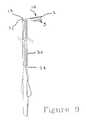
- FIG. 9is a view similar to FIG. 8 showing the distal end of the catheter including the preformed bend, extending exteriorly from the distal end of the guide tube;
- FIG. 10is a view similar to FIG. 9 showing the distal end of the catheter curled to form a halo in a plane at right angles to the axis of the guide tube by movement of the actuator in the direction of the arrow.
- the distal portion of the catheteris indicated generally at 10 and has a tubular flexible outer casing 3 with a distal end electrode 1 and a plurality of spaced electrodes 5 disposed thereon and preferably having an annular or ring shaped configuration.
- An initial permanent or pre-bend indicated generally at 12is formed in the region adjacent the proximal-most one of the distal ring electrodes 5 .
- the pre-bend 12is formed about the X axis and is formed to angle of about 90° and preferably about 83° for a casing of about 1.6 mm diameter (6 French) and for a minimum radius of 5 mm for the halo as shown in dashed outline in FIG.
- FIGS. 1 a through 1 cfor ease of illustration.
- the operation of the internal components of the catheter for affecting the flexing or curling for the halo as shown in FIGS. 1 b and 1 cwill be described hereinafter.
- the actuatoris of the type shown and described in my earlier U.S. Pat. No. 5,861,024.
- the flexible tubular casing of the catheteris shown denoted by reference numeral 3 has the ring shaped electrodes 5 disposed there over in axially spaced arrangement and spaced from the distal-most or tip electrode 1 .
- the tip electrode 1has a reduced diameter portion denoted by reference numeral 2 which has flattened end portions 9 , 11 of the tension/compression members 13 , 15 attached hereto.
- the portions 13 , 15have circular transverse sections, as do the portion 21 , 23 extending through the casing on the opposite side of the pre-formed bend 12 and through the casing to the proximal end of the catheter for attachment to an actuator.
- the flattened ends 9 , 11 of the tension/compression members 13 , 15are disposed in laterally spaced generally parallel arrangement with a resilient flexible spacer in the form of a laterally resilient wave-spring denoted by reference number 16 disposed there between.
- the flattened ends 9 , 11 of the tension/compression membersare preferably attached to the portion 2 of the distal electrode 1 by weldment such as, for example, brazing and thereby forming a kinematic junction at the distal electrode 1 with the tension/compression members 13 , 15 .
- the tension/compression members 13 , 15have on the proximal side of the pre-formed bend 12 a plastic sheath or tubing 25 received there over; and, in the present practice of the invention the tubing is formed of polyamide plastic material. However, it will be understood that alternatively other suitable plastic materials or a closely wound spring may be employed for the sheath or tubing 25 .
- the tip electrode 1 and each of the ring electrodes 5has an electrical lead attached thereto which lead extends through the casing 3 to the proximal end of the catheter as denoted respectively by the electrical lead 14 for the distal electrode 1 ; and, a typical lead for the ring electrodes 5 is denoted by reference numeral 18 .
- a bushing 29is received over the end of the shrink tube 7 ; and, the bushing 29 has attached thereto a braided sheath or exterior tube denoted by reference numeral 27 .
- Sheath 27has the distal end thereof abutted with casing 3 ; and, the opposite end extends to the proximal end of the catheter.
- the end of the bushing 29 opposite the braided sheath 27 on the distal end thereofis inserted within and attached to the proximal end of the non-braided casing 3 .
- the sheath or tube 25is formed of plastic material such as polyamide plastic and extends to the proximal end of the braided exterior tube 27 ; however, it will be understood that the tube material is not limited to polyamide and may be formed of other suitable thermo-plastic materials or a closely wound spring which may be made from stainless steel wire.
- the pre-formed bend 12is permanently formed in the catheter casing and the tension/compression members 13 , 15 .
- the distal end of the catheter with electrode 1is inserted in a guide tube placed in the patient's femoral vein; and, the portion of the catheter between electrode 1 and the pre-formed bend 12 is flexibly and temporarily resiliently flexed by the user to a position approximately parallel to that of the catheter casing 3 on the proximal side of the pre-formed bend 12 so as to permit insertion of the catheter into the proximal end of a guide tube inserted in the femoral vein.
- the pre-formed bend 12remains in its approximately right angle configuration.
- a guide tubeis shown at 30 which is of the type insert able into the femoral vein of the patient with the distal end 32 thereof entering into the first chamber of the heart as shown in FIG. 4 .
- FIG. 6the distal end of the catheter 10 with the preformed bend 12 therein is shown as disposed adjacent the proximal end 34 of the tube 30 prior to insertion therein.
- the distal end 10 of the catheteris manually deformed by the user from its initial position shown in dashed outline line to the position shown in solid line outline thereby forming a substantially “S” shaped offset in the catheter about the preformed bend 12 which remains formed in the catheter.
- the end 10With the end 10 held in the position shown in FIG. 6, the end 10 is inserted into the proximal end 34 of tube 30 and the catheter is pushed progressively through the guide tube as shown in FIGS. 7 and 8 until the distal end 10 thereof emerges from the distal end 32 of the guide tube 30 to return to its initial condition of FIG. 5 as shown in FIG. 9 except however with the end 10 disposed within a chamber in the heart as shown in FIG. 4 .
- the actuator indicated generally at 20has its movable member 22 moved in the direction shown by the black arrow in the FIG. 10 to cause the flattened ends 9 , 11 of the tension/compression members to effect curling of the distal end 10 of the catheter to the halo configuration as shown in FIG. 10 except however now with the heart chamber as shown in FIG. 4 .
- Formation of the curled or halo configuration of the catheter as shown in FIG. 1 c , FIG. 4, and FIG. 10permits further placement of the catheter in the interior of the pulmonary vein of the heart for permitting either mapping of the electrical signals of the interior, or inner periphery, of the pulmonary vein or the performance of the ablation procedures by the introduction of radio-frequency electric current into the electrode 5 .
- the catheteris shown with the distal end partially curled by movement of the remote actuator member 22 on actuator 20 .
- the catheter of the present inventionis shown in the fully looped or curled into a “halo” configuration where the pre-formed bend 12 formed about the X axis shown in FIG. 2 is retained; and, the distal portion of the catheter between distal electrode 1 and the pre-formed bend 12 has been flexibly curled, by the movement of the tension/compression members 21 , 23 , as shown by the black arrows in FIG. 3, to cause the distal portion of the catheter to form a loop or 270 degree bend about the Z axis, or in other words forming a loop in X-Y plane with reference to the axes shown in FIG. 3 .
- the catheteris capable of bi-directional curling by movement of the remote actuator in opposite directions.
- the outer diameter of the catheter casingis in the same range of about 0.062 inches to 0.092 inches (1.6 mm to 2.3 mm); and, the ring electrodes 5 are spaced about 0.080 inches to 0.200 inches (2 mm to 5 mm) apart along the axis of the casing.
- the catheterhas accommodated 11 ring electrodes in addition to the distal electrode.
- a catheter having a casing diameter in the range of about 0.062 inches to 0.092 inches (1.6 mm to 2.3 mm)is capable of being curled into a halo having an inside diameter as small as 0.400 inches (10 mm) when the catheter is flexibly deformed by movement of the manual actuator 22 to move the tension/compression members 15 , 17 .
Landscapes
- Health & Medical Sciences (AREA)
- Life Sciences & Earth Sciences (AREA)
- Surgery (AREA)
- Engineering & Computer Science (AREA)
- Plasma & Fusion (AREA)
- Medical Informatics (AREA)
- Otolaryngology (AREA)
- Physics & Mathematics (AREA)
- Cardiology (AREA)
- Biomedical Technology (AREA)
- Heart & Thoracic Surgery (AREA)
- Nuclear Medicine, Radiotherapy & Molecular Imaging (AREA)
- Molecular Biology (AREA)
- Animal Behavior & Ethology (AREA)
- General Health & Medical Sciences (AREA)
- Public Health (AREA)
- Veterinary Medicine (AREA)
- Surgical Instruments (AREA)
- Media Introduction/Drainage Providing Device (AREA)
Abstract
Description
Claims (13)
Priority Applications (4)
| Application Number | Priority Date | Filing Date | Title |
|---|---|---|---|
| US09/726,235US6728563B2 (en) | 2000-11-29 | 2000-11-29 | Electrophysiology/ablation catheter having “halo” configuration |
| US10/436,779US7081114B2 (en) | 2000-11-29 | 2003-05-13 | Electrophysiology/ablation catheter having lariat configuration of variable radius |
| US11/449,253US8758338B2 (en) | 2000-11-29 | 2006-06-07 | Electrophysiology/ablation catheter having lariat configuration of variable radius |
| US14/311,515US10143516B2 (en) | 2000-11-29 | 2014-06-23 | Electrophysiology/ablation catheter having lariat configuration of variable radius |
Applications Claiming Priority (1)
| Application Number | Priority Date | Filing Date | Title |
|---|---|---|---|
| US09/726,235US6728563B2 (en) | 2000-11-29 | 2000-11-29 | Electrophysiology/ablation catheter having “halo” configuration |
Related Child Applications (1)
| Application Number | Title | Priority Date | Filing Date |
|---|---|---|---|
| US10/436,779Continuation-In-PartUS7081114B2 (en) | 2000-11-29 | 2003-05-13 | Electrophysiology/ablation catheter having lariat configuration of variable radius |
Publications (2)
| Publication Number | Publication Date |
|---|---|
| US20020065514A1 US20020065514A1 (en) | 2002-05-30 |
| US6728563B2true US6728563B2 (en) | 2004-04-27 |
Family
ID=24917736
Family Applications (1)
| Application Number | Title | Priority Date | Filing Date |
|---|---|---|---|
| US09/726,235Expired - LifetimeUS6728563B2 (en) | 2000-11-29 | 2000-11-29 | Electrophysiology/ablation catheter having “halo” configuration |
Country Status (1)
| Country | Link |
|---|---|
| US (1) | US6728563B2 (en) |
Cited By (55)
| Publication number | Priority date | Publication date | Assignee | Title |
|---|---|---|---|---|
| US20060095030A1 (en)* | 2004-11-04 | 2006-05-04 | Scimed Life Systems, Inc. | Preshaped ablation catheter for ablating pulmonary vein ostia within the heart |
| US20060241366A1 (en)* | 2002-10-31 | 2006-10-26 | Gary Falwell | Electrophysiology loop catheter |
| US20060253115A1 (en)* | 2005-05-05 | 2006-11-09 | Boaz Avitall | Steerable catheter and method for performing medical procedure adjacent pulmonary vein ostia |
| US20070129720A1 (en)* | 2002-04-08 | 2007-06-07 | Ardian, Inc. | Methods and apparatus for performing a non-continuous circumferential treatment of a body lumen |
| US20070156116A1 (en)* | 2005-12-30 | 2007-07-05 | Gonzalez Pablo A | Dual-lever bi-directional handle |
| US20080039918A1 (en)* | 2001-04-27 | 2008-02-14 | C.R. Bard, Inc. | Electrophysiology catheter for mapping and/or ablation |
| US20080082136A1 (en)* | 2006-10-03 | 2008-04-03 | Gaudiani Vincent A | Transcoronary Sinus Pacing System, LV Summit Pacing, Early Mitral Closure Pacing, and Methods Therefor |
| US20100168739A1 (en)* | 2008-12-31 | 2010-07-01 | Ardian, Inc. | Apparatus, systems, and methods for achieving intravascular, thermally-induced renal neuromodulation |
| US20110301536A1 (en)* | 1997-06-20 | 2011-12-08 | Rassoll Rashidi | Electrophysiology/ablation catheter having second passage |
| JP2013135857A (en)* | 2006-05-17 | 2013-07-11 | St Jude Medical Atrial Fibrillation Division Inc | Auto lock for catheter handle |
| US8932208B2 (en) | 2005-05-26 | 2015-01-13 | Maquet Cardiovascular Llc | Apparatus and methods for performing minimally-invasive surgical procedures |
| US8974445B2 (en) | 2009-01-09 | 2015-03-10 | Recor Medical, Inc. | Methods and apparatus for treatment of cardiac valve insufficiency |
| US9125661B2 (en) | 2002-04-08 | 2015-09-08 | Medtronic Ardian Luxembourg S.A.R.L. | Methods and apparatus for renal neuromodulation |
| US9131978B2 (en) | 2002-04-08 | 2015-09-15 | Medtronic Ardian Luxembourg S.A.R.L. | Methods for bilateral renal neuromodulation |
| US9694159B2 (en) | 2005-06-28 | 2017-07-04 | St. Jude Medical, Atrial Fibrillation Division, Inc. | Auto lock for catheter handle |
| US9700372B2 (en) | 2002-07-01 | 2017-07-11 | Recor Medical, Inc. | Intraluminal methods of ablating nerve tissue |
| US9724170B2 (en) | 2012-08-09 | 2017-08-08 | University Of Iowa Research Foundation | Catheters, catheter systems, and methods for puncturing through a tissue structure and ablating a tissue region |
| US9987081B1 (en) | 2017-04-27 | 2018-06-05 | Iowa Approach, Inc. | Systems, devices, and methods for signal generation |
| US9999461B2 (en) | 2011-12-09 | 2018-06-19 | Metavention, Inc. | Therapeutic denervation of nerves surrounding a hepatic vessel |
| US9999465B2 (en) | 2014-10-14 | 2018-06-19 | Iowa Approach, Inc. | Method and apparatus for rapid and safe pulmonary vein cardiac ablation |
| US10058380B2 (en) | 2007-10-05 | 2018-08-28 | Maquet Cordiovascular Llc | Devices and methods for minimally-invasive surgical procedures |
| US10130423B1 (en) | 2017-07-06 | 2018-11-20 | Farapulse, Inc. | Systems, devices, and methods for focal ablation |
| US10172673B2 (en) | 2016-01-05 | 2019-01-08 | Farapulse, Inc. | Systems devices, and methods for delivery of pulsed electric field ablative energy to endocardial tissue |
| US10322286B2 (en) | 2016-01-05 | 2019-06-18 | Farapulse, Inc. | Systems, apparatuses and methods for delivery of ablative energy to tissue |
| US10433906B2 (en) | 2014-06-12 | 2019-10-08 | Farapulse, Inc. | Method and apparatus for rapid and selective transurethral tissue ablation |
| US10507302B2 (en) | 2016-06-16 | 2019-12-17 | Farapulse, Inc. | Systems, apparatuses, and methods for guide wire delivery |
| US10512505B2 (en) | 2018-05-07 | 2019-12-24 | Farapulse, Inc. | Systems, apparatuses and methods for delivery of ablative energy to tissue |
| US10517672B2 (en) | 2014-01-06 | 2019-12-31 | Farapulse, Inc. | Apparatus and methods for renal denervation ablation |
| US10524859B2 (en) | 2016-06-07 | 2020-01-07 | Metavention, Inc. | Therapeutic tissue modulation devices and methods |
| US10537385B2 (en) | 2008-12-31 | 2020-01-21 | Medtronic Ardian Luxembourg S.A.R.L. | Intravascular, thermally-induced renal neuromodulation for treatment of polycystic ovary syndrome or infertility |
| US10617867B2 (en) | 2017-04-28 | 2020-04-14 | Farapulse, Inc. | Systems, devices, and methods for delivery of pulsed electric field ablative energy to esophageal tissue |
| US10625080B1 (en) | 2019-09-17 | 2020-04-21 | Farapulse, Inc. | Systems, apparatuses, and methods for detecting ectopic electrocardiogram signals during pulsed electric field ablation |
| US10624693B2 (en) | 2014-06-12 | 2020-04-21 | Farapulse, Inc. | Method and apparatus for rapid and selective tissue ablation with cooling |
| US10660702B2 (en) | 2016-01-05 | 2020-05-26 | Farapulse, Inc. | Systems, devices, and methods for focal ablation |
| US10675443B2 (en) | 2016-03-07 | 2020-06-09 | St. Jude Medical, Cardiology Division, Inc. | Medical device including an actuator restraining assembly |
| US10687892B2 (en) | 2018-09-20 | 2020-06-23 | Farapulse, Inc. | Systems, apparatuses, and methods for delivery of pulsed electric field ablative energy to endocardial tissue |
| US10842572B1 (en) | 2019-11-25 | 2020-11-24 | Farapulse, Inc. | Methods, systems, and apparatuses for tracking ablation devices and generating lesion lines |
| US10893905B2 (en) | 2017-09-12 | 2021-01-19 | Farapulse, Inc. | Systems, apparatuses, and methods for ventricular focal ablation |
| US11020180B2 (en) | 2018-05-07 | 2021-06-01 | Farapulse, Inc. | Epicardial ablation catheter |
| US11033236B2 (en) | 2018-05-07 | 2021-06-15 | Farapulse, Inc. | Systems, apparatuses, and methods for filtering high voltage noise induced by pulsed electric field ablation |
| US11065047B2 (en) | 2019-11-20 | 2021-07-20 | Farapulse, Inc. | Systems, apparatuses, and methods for protecting electronic components from high power noise induced by high voltage pulses |
| US11259869B2 (en) | 2014-05-07 | 2022-03-01 | Farapulse, Inc. | Methods and apparatus for selective tissue ablation |
| US11497541B2 (en) | 2019-11-20 | 2022-11-15 | Boston Scientific Scimed, Inc. | Systems, apparatuses, and methods for protecting electronic components from high power noise induced by high voltage pulses |
| US11577075B1 (en) | 2018-10-12 | 2023-02-14 | Vincent A. Gaudiani | Transcoronary sinus pacing of his bundle |
| US11648397B1 (en) | 2018-10-12 | 2023-05-16 | Vincent Gaudiani | Transcoronary sinus pacing of posteroseptal left ventricular base |
| US12011212B2 (en) | 2013-06-05 | 2024-06-18 | Medtronic Ireland Manufacturing Unlimited Company | Modulation of targeted nerve fibers |
| US12042208B2 (en) | 2018-05-03 | 2024-07-23 | Boston Scientific Scimed, Inc. | Systems, devices, and methods for ablation using surgical clamps |
| US12137968B2 (en) | 2014-05-16 | 2024-11-12 | Boston Scientific Scimed, Inc. | Methods and apparatus for multi-catheter tissue ablation |
| US12144541B2 (en) | 2016-01-05 | 2024-11-19 | Boston Scientific Scimed, Inc. | Systems, apparatuses and methods for delivery of ablative energy to tissue |
| US12268437B2 (en) | 2020-07-24 | 2025-04-08 | Boston Scientific Scimed, Inc. | Electric field application for single shot cardiac ablation by irreversible electroporation |
| US12295637B2 (en) | 2018-02-08 | 2025-05-13 | Boston Scientific Scimed, Inc. | Method and apparatus for controlled delivery of pulsed electric field ablative energy to tissue |
| US12310652B2 (en) | 2020-07-24 | 2025-05-27 | Boston Scientific Scimed, Inc. | Hybrid electroporation ablation catheter |
| US12343071B2 (en) | 2021-01-27 | 2025-07-01 | Boston Scientific Scimed, Inc | Voltage controlled pulse sequences for irreversible electroporation ablations |
| US12349964B2 (en) | 2020-09-30 | 2025-07-08 | Boston Scientific Scimed, Inc. | Pretreatment waveform for irreversible electroporation |
| US12408974B2 (en) | 2014-12-03 | 2025-09-09 | Medtronic Ireland Manufacturing Unlimited Company | Systems and methods for modulating nerves or other tissue |
Families Citing this family (7)
| Publication number | Priority date | Publication date | Assignee | Title |
|---|---|---|---|---|
| US7218958B2 (en)* | 2004-02-23 | 2007-05-15 | St. Jude Medical, Atrial Fibrillation Division, Inc. | Electrophysiology/ablation catheter having second passage |
| US7245955B2 (en) | 2004-02-23 | 2007-07-17 | St. Jude Medical, Atrial Fibrillation Division, Inc. | Electrophysiology/ablation catheter having deflection assembly |
| US8369923B2 (en)* | 2010-04-14 | 2013-02-05 | St. Jude Medical, Atrial Fibrillation Division, Inc. | Dual-deflecting electrophysiology catheter |
| US9827036B2 (en) | 2012-11-13 | 2017-11-28 | Pulnovo Medical (Wuxi) Co., Ltd. | Multi-pole synchronous pulmonary artery radiofrequency ablation catheter |
| CN102908191A (en) | 2012-11-13 | 2013-02-06 | 陈绍良 | Multipolar synchronous pulmonary artery radiofrequency ablation catheter |
| US11241267B2 (en) | 2012-11-13 | 2022-02-08 | Pulnovo Medical (Wuxi) Co., Ltd | Multi-pole synchronous pulmonary artery radiofrequency ablation catheter |
| US12082868B2 (en) | 2012-11-13 | 2024-09-10 | Pulnovo Medical (Wuxi) Co., Ltd. | Multi-pole synchronous pulmonary artery radiofrequency ablation catheter |
Citations (20)
| Publication number | Priority date | Publication date | Assignee | Title |
|---|---|---|---|---|
| US4920980A (en) | 1987-09-14 | 1990-05-01 | Cordis Corporation | Catheter with controllable tip |
| US4960134A (en) | 1988-11-18 | 1990-10-02 | Webster Wilton W Jr | Steerable catheter |
| US5125896A (en) | 1990-10-10 | 1992-06-30 | C. R. Bard, Inc. | Steerable electrode catheter |
| US5354297A (en) | 1992-02-14 | 1994-10-11 | Boaz Avitall | Biplanar deflectable catheter for arrhythmogenic tissue ablation |
| US5462527A (en) | 1993-06-29 | 1995-10-31 | C.R. Bard, Inc. | Actuator for use with steerable catheter |
| US5588964A (en) | 1992-12-01 | 1996-12-31 | Cardiac Pathways Corporation | Steerable catheter with adjustable bend location and/or radius and method |
| US5611777A (en) | 1993-05-14 | 1997-03-18 | C.R. Bard, Inc. | Steerable electrode catheter |
| US5673695A (en) | 1995-08-02 | 1997-10-07 | Ep Technologies, Inc. | Methods for locating and ablating accessory pathways in the heart |
| US5715817A (en) | 1993-06-29 | 1998-02-10 | C.R. Bard, Inc. | Bidirectional steering catheter |
| US5755760A (en) | 1996-03-11 | 1998-05-26 | Medtronic, Inc. | Deflectable catheter |
| US5807249A (en) | 1996-02-16 | 1998-09-15 | Medtronic, Inc. | Reduced stiffness, bidirectionally deflecting catheter assembly |
| US5820591A (en) | 1990-02-02 | 1998-10-13 | E. P. Technologies, Inc. | Assemblies for creating compound curves in distal catheter regions |
| US5861024A (en) | 1997-06-20 | 1999-01-19 | Cardiac Assist Devices, Inc | Electrophysiology catheter and remote actuator therefor |
| US5938694A (en) | 1993-11-10 | 1999-08-17 | Medtronic Cardiorhythm | Electrode array catheter |
| US5944690A (en) | 1997-03-17 | 1999-08-31 | C.R. Bard, Inc. | Slidable control mechanism for steerable catheter |
| US5987344A (en) | 1996-08-08 | 1999-11-16 | Medtronic, Inc. | Handle for catheter assembly with multifunction wire |
| US6002955A (en) | 1996-11-08 | 1999-12-14 | Medtronic, Inc. | Stabilized electrophysiology catheter and method for use |
| US6183463B1 (en) | 1997-12-01 | 2001-02-06 | Cordis Webster, Inc. | Bidirectional steerable cathether with bidirectional control handle |
| US6308090B1 (en)* | 1998-03-09 | 2001-10-23 | Irvine Biomedical, Inc. | Devices and methods for coronary sinus mapping |
| US6325797B1 (en)* | 1999-04-05 | 2001-12-04 | Medtronic, Inc. | Ablation catheter and method for isolating a pulmonary vein |
- 2000
- 2000-11-29USUS09/726,235patent/US6728563B2/ennot_activeExpired - Lifetime
Patent Citations (24)
| Publication number | Priority date | Publication date | Assignee | Title |
|---|---|---|---|---|
| US4920980A (en) | 1987-09-14 | 1990-05-01 | Cordis Corporation | Catheter with controllable tip |
| US4960134A (en) | 1988-11-18 | 1990-10-02 | Webster Wilton W Jr | Steerable catheter |
| USRE34502E (en) | 1988-11-18 | 1994-01-11 | Webster, Jr.; Wilton W. | Steerable catheter |
| US5820591A (en) | 1990-02-02 | 1998-10-13 | E. P. Technologies, Inc. | Assemblies for creating compound curves in distal catheter regions |
| US5125896A (en) | 1990-10-10 | 1992-06-30 | C. R. Bard, Inc. | Steerable electrode catheter |
| US5354297A (en) | 1992-02-14 | 1994-10-11 | Boaz Avitall | Biplanar deflectable catheter for arrhythmogenic tissue ablation |
| US5588964A (en) | 1992-12-01 | 1996-12-31 | Cardiac Pathways Corporation | Steerable catheter with adjustable bend location and/or radius and method |
| US5656029A (en) | 1992-12-01 | 1997-08-12 | Cardiac Pathways Corporation | Steerable catheter with adjustable bend location and/or radius and method |
| US5611777A (en) | 1993-05-14 | 1997-03-18 | C.R. Bard, Inc. | Steerable electrode catheter |
| US5935102A (en) | 1993-05-14 | 1999-08-10 | C. R. Bard | Steerable electrode catheter |
| US5715817A (en) | 1993-06-29 | 1998-02-10 | C.R. Bard, Inc. | Bidirectional steering catheter |
| US5462527A (en) | 1993-06-29 | 1995-10-31 | C.R. Bard, Inc. | Actuator for use with steerable catheter |
| US5938694A (en) | 1993-11-10 | 1999-08-17 | Medtronic Cardiorhythm | Electrode array catheter |
| US5673695A (en) | 1995-08-02 | 1997-10-07 | Ep Technologies, Inc. | Methods for locating and ablating accessory pathways in the heart |
| US5807249A (en) | 1996-02-16 | 1998-09-15 | Medtronic, Inc. | Reduced stiffness, bidirectionally deflecting catheter assembly |
| US5755760A (en) | 1996-03-11 | 1998-05-26 | Medtronic, Inc. | Deflectable catheter |
| US6356790B1 (en)* | 1996-03-11 | 2002-03-12 | Medtronic, Inc. | Apparatus for R-F ablation |
| US5987344A (en) | 1996-08-08 | 1999-11-16 | Medtronic, Inc. | Handle for catheter assembly with multifunction wire |
| US6002955A (en) | 1996-11-08 | 1999-12-14 | Medtronic, Inc. | Stabilized electrophysiology catheter and method for use |
| US5944690A (en) | 1997-03-17 | 1999-08-31 | C.R. Bard, Inc. | Slidable control mechanism for steerable catheter |
| US5861024A (en) | 1997-06-20 | 1999-01-19 | Cardiac Assist Devices, Inc | Electrophysiology catheter and remote actuator therefor |
| US6183463B1 (en) | 1997-12-01 | 2001-02-06 | Cordis Webster, Inc. | Bidirectional steerable cathether with bidirectional control handle |
| US6308090B1 (en)* | 1998-03-09 | 2001-10-23 | Irvine Biomedical, Inc. | Devices and methods for coronary sinus mapping |
| US6325797B1 (en)* | 1999-04-05 | 2001-12-04 | Medtronic, Inc. | Ablation catheter and method for isolating a pulmonary vein |
Cited By (119)
| Publication number | Priority date | Publication date | Assignee | Title |
|---|---|---|---|---|
| US20110301536A1 (en)* | 1997-06-20 | 2011-12-08 | Rassoll Rashidi | Electrophysiology/ablation catheter having second passage |
| US8206384B2 (en)* | 2001-04-27 | 2012-06-26 | C. R. Bard, Inc. | Electrophysiology catheter for mapping and/or ablation |
| US9750567B2 (en)* | 2001-04-27 | 2017-09-05 | Boston Scientific Scimed Inc. | Electrophysiology catheter for mapping and/or ablation |
| US20140107644A1 (en)* | 2001-04-27 | 2014-04-17 | Boston Scientific Scimed, Inc. | Electrophysiology catheter for mapping and/or ablation |
| US20080039918A1 (en)* | 2001-04-27 | 2008-02-14 | C.R. Bard, Inc. | Electrophysiology catheter for mapping and/or ablation |
| US8636731B2 (en)* | 2001-04-27 | 2014-01-28 | Boston Scientific Scimed, Inc. | Electrophysiology catheter for mapping and/or ablation |
| US20120310065A1 (en)* | 2001-04-27 | 2012-12-06 | C.R. Bard, Inc. | Electrophysiology catheter for mapping and/or ablation |
| US9131978B2 (en) | 2002-04-08 | 2015-09-15 | Medtronic Ardian Luxembourg S.A.R.L. | Methods for bilateral renal neuromodulation |
| US9125661B2 (en) | 2002-04-08 | 2015-09-08 | Medtronic Ardian Luxembourg S.A.R.L. | Methods and apparatus for renal neuromodulation |
| US20070129720A1 (en)* | 2002-04-08 | 2007-06-07 | Ardian, Inc. | Methods and apparatus for performing a non-continuous circumferential treatment of a body lumen |
| US8347891B2 (en)* | 2002-04-08 | 2013-01-08 | Medtronic Ardian Luxembourg S.A.R.L. | Methods and apparatus for performing a non-continuous circumferential treatment of a body lumen |
| US9700372B2 (en) | 2002-07-01 | 2017-07-11 | Recor Medical, Inc. | Intraluminal methods of ablating nerve tissue |
| US9707034B2 (en) | 2002-07-01 | 2017-07-18 | Recor Medical, Inc. | Intraluminal method and apparatus for ablating nerve tissue |
| US8961509B2 (en) | 2002-10-31 | 2015-02-24 | Boston Scientific Scimed, Inc. | Electrophysiology loop catheter |
| US20060241366A1 (en)* | 2002-10-31 | 2006-10-26 | Gary Falwell | Electrophysiology loop catheter |
| US9186481B2 (en) | 2004-11-04 | 2015-11-17 | Boston Scientific Scimed Inc. | Preshaped ablation catheter for ablating pulmonary vein ostia within the heart |
| US20060095030A1 (en)* | 2004-11-04 | 2006-05-04 | Scimed Life Systems, Inc. | Preshaped ablation catheter for ablating pulmonary vein ostia within the heart |
| US8409191B2 (en) | 2004-11-04 | 2013-04-02 | Boston Scientific Scimed, Inc. | Preshaped ablation catheter for ablating pulmonary vein ostia within the heart |
| US9320564B2 (en) | 2005-05-05 | 2016-04-26 | Boston Scientific Scimed Inc. | Steerable catheter and method for performing medical procedure adjacent pulmonary vein ostia |
| US8535303B2 (en) | 2005-05-05 | 2013-09-17 | Boston Scientific Scimed, Inc. | Preshaped localization catheter, system, and method for graphically reconstructing pulmonary vein ostia |
| US8784414B2 (en) | 2005-05-05 | 2014-07-22 | Boston Scientific Scimed, Inc. | Preshaped localization catheter, system, and method for graphically reconstructing pulmonary vein ostia |
| US20060253116A1 (en)* | 2005-05-05 | 2006-11-09 | Boaz Avitall | Preshaped localization catheter, system, and method for graphically reconstructing pulmonary vein ostia |
| US20060253115A1 (en)* | 2005-05-05 | 2006-11-09 | Boaz Avitall | Steerable catheter and method for performing medical procedure adjacent pulmonary vein ostia |
| US8932208B2 (en) | 2005-05-26 | 2015-01-13 | Maquet Cardiovascular Llc | Apparatus and methods for performing minimally-invasive surgical procedures |
| US10737062B2 (en) | 2005-06-28 | 2020-08-11 | St. Jude Medical, Atrial Fibrillation Division, Inc. | Auto lock for catheter handle |
| US9694159B2 (en) | 2005-06-28 | 2017-07-04 | St. Jude Medical, Atrial Fibrillation Division, Inc. | Auto lock for catheter handle |
| US9833595B2 (en)* | 2005-12-30 | 2017-12-05 | Biosense Webster, Inc. | Dual-lever bi-directional handle |
| US10569053B2 (en) | 2005-12-30 | 2020-02-25 | Biosense Webster, Inc. | Dual-lever bi-directional handle |
| US20070156116A1 (en)* | 2005-12-30 | 2007-07-05 | Gonzalez Pablo A | Dual-lever bi-directional handle |
| US11511078B2 (en) | 2005-12-30 | 2022-11-29 | Biosense Webster, Inc. | Dual-lever bi-directional handle |
| JP2013135857A (en)* | 2006-05-17 | 2013-07-11 | St Jude Medical Atrial Fibrillation Division Inc | Auto lock for catheter handle |
| US20080082136A1 (en)* | 2006-10-03 | 2008-04-03 | Gaudiani Vincent A | Transcoronary Sinus Pacing System, LV Summit Pacing, Early Mitral Closure Pacing, and Methods Therefor |
| US10369356B2 (en) | 2006-10-03 | 2019-08-06 | Case Western Reserve University | Transcoronary sinus pacing system, LV summit pacing, early mitral closure pacing, and methods therefor |
| US9265938B2 (en) | 2006-10-03 | 2016-02-23 | Vincent A. Gaudiani | Transcoronary sinus pacing system, LV summit pacing, early mitral closure pacing, and methods therefor |
| US8634935B2 (en) | 2006-10-03 | 2014-01-21 | Vincent A. Gaudiani | Transcoronary sinus pacing system, LV summit pacing, early mitral closure pacing, and methods therefor |
| US8068920B2 (en) | 2006-10-03 | 2011-11-29 | Vincent A Gaudiani | Transcoronary sinus pacing system, LV summit pacing, early mitral closure pacing, and methods therefor |
| US10993766B2 (en) | 2007-10-05 | 2021-05-04 | Maquet Cardiovascular Llc | Devices and methods for minimally-invasive surgical procedures |
| US10058380B2 (en) | 2007-10-05 | 2018-08-28 | Maquet Cordiovascular Llc | Devices and methods for minimally-invasive surgical procedures |
| US20100168739A1 (en)* | 2008-12-31 | 2010-07-01 | Ardian, Inc. | Apparatus, systems, and methods for achieving intravascular, thermally-induced renal neuromodulation |
| US10561460B2 (en) | 2008-12-31 | 2020-02-18 | Medtronic Ardian Luxembourg S.A.R.L. | Neuromodulation systems and methods for treatment of sexual dysfunction |
| US10537385B2 (en) | 2008-12-31 | 2020-01-21 | Medtronic Ardian Luxembourg S.A.R.L. | Intravascular, thermally-induced renal neuromodulation for treatment of polycystic ovary syndrome or infertility |
| US8974445B2 (en) | 2009-01-09 | 2015-03-10 | Recor Medical, Inc. | Methods and apparatus for treatment of cardiac valve insufficiency |
| US10617460B2 (en) | 2011-12-09 | 2020-04-14 | Metavention, Inc. | Neuromodulation for metabolic conditions or syndromes |
| US12029466B2 (en) | 2011-12-09 | 2024-07-09 | Medtronic Ireland Manufacturing Unlimited Company | Neuromodulation for metabolic conditions or syndromes |
| US10856926B2 (en) | 2011-12-09 | 2020-12-08 | Metavention, Inc. | Neuromodulation for metabolic conditions or syndromes |
| US9999461B2 (en) | 2011-12-09 | 2018-06-19 | Metavention, Inc. | Therapeutic denervation of nerves surrounding a hepatic vessel |
| US10070911B2 (en) | 2011-12-09 | 2018-09-11 | Metavention, Inc. | Neuromodulation methods to alter glucose levels |
| US10543034B2 (en) | 2011-12-09 | 2020-01-28 | Metavention, Inc. | Modulation of nerves innervating the liver |
| US10064674B2 (en) | 2011-12-09 | 2018-09-04 | Metavention, Inc. | Methods of modulating nerves of the hepatic plexus |
| US9724170B2 (en) | 2012-08-09 | 2017-08-08 | University Of Iowa Research Foundation | Catheters, catheter systems, and methods for puncturing through a tissue structure and ablating a tissue region |
| US9861802B2 (en) | 2012-08-09 | 2018-01-09 | University Of Iowa Research Foundation | Catheters, catheter systems, and methods for puncturing through a tissue structure |
| US11426573B2 (en) | 2012-08-09 | 2022-08-30 | University Of Iowa Research Foundation | Catheters, catheter systems, and methods for puncturing through a tissue structure and ablating a tissue region |
| US12011212B2 (en) | 2013-06-05 | 2024-06-18 | Medtronic Ireland Manufacturing Unlimited Company | Modulation of targeted nerve fibers |
| US11589919B2 (en) | 2014-01-06 | 2023-02-28 | Boston Scientific Scimed, Inc. | Apparatus and methods for renal denervation ablation |
| US10517672B2 (en) | 2014-01-06 | 2019-12-31 | Farapulse, Inc. | Apparatus and methods for renal denervation ablation |
| US12408979B2 (en) | 2014-05-07 | 2025-09-09 | Boston Scientific Scimed, Inc. | Methods and apparatus for selective tissue ablation |
| US12390272B2 (en) | 2014-05-07 | 2025-08-19 | Boston Scientific Scimed, Inc. | Methods and apparatus for selective tissue ablation |
| US11259869B2 (en) | 2014-05-07 | 2022-03-01 | Farapulse, Inc. | Methods and apparatus for selective tissue ablation |
| US12137968B2 (en) | 2014-05-16 | 2024-11-12 | Boston Scientific Scimed, Inc. | Methods and apparatus for multi-catheter tissue ablation |
| US11622803B2 (en) | 2014-06-12 | 2023-04-11 | Boston Scientific Scimed, Inc. | Method and apparatus for rapid and selective tissue ablation with cooling |
| US10624693B2 (en) | 2014-06-12 | 2020-04-21 | Farapulse, Inc. | Method and apparatus for rapid and selective tissue ablation with cooling |
| US12161397B2 (en) | 2014-06-12 | 2024-12-10 | Boston Scientific Scimed, Inc. | Method and apparatus for rapid and selective transurethral tissue ablation |
| US11241282B2 (en) | 2014-06-12 | 2022-02-08 | Boston Scientific Scimed, Inc. | Method and apparatus for rapid and selective transurethral tissue ablation |
| US10433906B2 (en) | 2014-06-12 | 2019-10-08 | Farapulse, Inc. | Method and apparatus for rapid and selective transurethral tissue ablation |
| US10835314B2 (en) | 2014-10-14 | 2020-11-17 | Farapulse, Inc. | Method and apparatus for rapid and safe pulmonary vein cardiac ablation |
| US9999465B2 (en) | 2014-10-14 | 2018-06-19 | Iowa Approach, Inc. | Method and apparatus for rapid and safe pulmonary vein cardiac ablation |
| US12295648B2 (en) | 2014-10-14 | 2025-05-13 | Boston Scientific Scimed, Inc. | Method and apparatus for rapid and safe pulmonary vein cardiac ablation |
| US12408974B2 (en) | 2014-12-03 | 2025-09-09 | Medtronic Ireland Manufacturing Unlimited Company | Systems and methods for modulating nerves or other tissue |
| US10660702B2 (en) | 2016-01-05 | 2020-05-26 | Farapulse, Inc. | Systems, devices, and methods for focal ablation |
| US12144541B2 (en) | 2016-01-05 | 2024-11-19 | Boston Scientific Scimed, Inc. | Systems, apparatuses and methods for delivery of ablative energy to tissue |
| US10709891B2 (en) | 2016-01-05 | 2020-07-14 | Farapulse, Inc. | Systems, apparatuses and methods for delivery of ablative energy to tissue |
| US10172673B2 (en) | 2016-01-05 | 2019-01-08 | Farapulse, Inc. | Systems devices, and methods for delivery of pulsed electric field ablative energy to endocardial tissue |
| US10842561B2 (en) | 2016-01-05 | 2020-11-24 | Farapulse, Inc. | Systems, devices, and methods for delivery of pulsed electric field ablative energy to endocardial tissue |
| US10322286B2 (en) | 2016-01-05 | 2019-06-18 | Farapulse, Inc. | Systems, apparatuses and methods for delivery of ablative energy to tissue |
| US11589921B2 (en) | 2016-01-05 | 2023-02-28 | Boston Scientific Scimed, Inc. | Systems, apparatuses and methods for delivery of ablative energy to tissue |
| US10433908B2 (en) | 2016-01-05 | 2019-10-08 | Farapulse, Inc. | Systems, devices, and methods for delivery of pulsed electric field ablative energy to endocardial tissue |
| US10512779B2 (en) | 2016-01-05 | 2019-12-24 | Farapulse, Inc. | Systems, apparatuses and methods for delivery of ablative energy to tissue |
| US11020179B2 (en) | 2016-01-05 | 2021-06-01 | Farapulse, Inc. | Systems, devices, and methods for focal ablation |
| US11517714B2 (en) | 2016-03-07 | 2022-12-06 | St. Jude Medical, Cardiology Division, Inc. | Medical device including an actuator restraining assembly |
| US10675443B2 (en) | 2016-03-07 | 2020-06-09 | St. Jude Medical, Cardiology Division, Inc. | Medical device including an actuator restraining assembly |
| US10524859B2 (en) | 2016-06-07 | 2020-01-07 | Metavention, Inc. | Therapeutic tissue modulation devices and methods |
| US12246143B2 (en) | 2016-06-16 | 2025-03-11 | Boston Scientific Scimed, Inc. | Systems, apparatuses, and methods for guide wire delivery |
| US10507302B2 (en) | 2016-06-16 | 2019-12-17 | Farapulse, Inc. | Systems, apparatuses, and methods for guide wire delivery |
| US11357978B2 (en) | 2017-04-27 | 2022-06-14 | Boston Scientific Scimed, Inc. | Systems, devices, and methods for signal generation |
| US10016232B1 (en) | 2017-04-27 | 2018-07-10 | Iowa Approach, Inc. | Systems, devices, and methods for signal generation |
| US12121720B2 (en) | 2017-04-27 | 2024-10-22 | Boston Scientific Scimed, Inc. | Systems, devices, and methods for signal generation |
| US9987081B1 (en) | 2017-04-27 | 2018-06-05 | Iowa Approach, Inc. | Systems, devices, and methods for signal generation |
| US10617867B2 (en) | 2017-04-28 | 2020-04-14 | Farapulse, Inc. | Systems, devices, and methods for delivery of pulsed electric field ablative energy to esophageal tissue |
| US11833350B2 (en) | 2017-04-28 | 2023-12-05 | Boston Scientific Scimed, Inc. | Systems, devices, and methods for delivery of pulsed electric field ablative energy to esophageal tissue |
| US10130423B1 (en) | 2017-07-06 | 2018-11-20 | Farapulse, Inc. | Systems, devices, and methods for focal ablation |
| US10617467B2 (en) | 2017-07-06 | 2020-04-14 | Farapulse, Inc. | Systems, devices, and methods for focal ablation |
| US12150698B2 (en) | 2017-09-12 | 2024-11-26 | Boston Scientific Scimed, Inc. | Systems, apparatuses, and methods for ventricular focal ablation |
| US10893905B2 (en) | 2017-09-12 | 2021-01-19 | Farapulse, Inc. | Systems, apparatuses, and methods for ventricular focal ablation |
| US12295637B2 (en) | 2018-02-08 | 2025-05-13 | Boston Scientific Scimed, Inc. | Method and apparatus for controlled delivery of pulsed electric field ablative energy to tissue |
| US12042208B2 (en) | 2018-05-03 | 2024-07-23 | Boston Scientific Scimed, Inc. | Systems, devices, and methods for ablation using surgical clamps |
| US12257080B2 (en) | 2018-05-07 | 2025-03-25 | Boston Scientific Scimed, Inc. | Systems, apparatuses, and methods for filtering high voltage noise induced by pulsed electric field ablation |
| US11033236B2 (en) | 2018-05-07 | 2021-06-15 | Farapulse, Inc. | Systems, apparatuses, and methods for filtering high voltage noise induced by pulsed electric field ablation |
| US10709502B2 (en) | 2018-05-07 | 2020-07-14 | Farapulse, Inc. | Systems, apparatuses and methods for delivery of ablative energy to tissue |
| US11020180B2 (en) | 2018-05-07 | 2021-06-01 | Farapulse, Inc. | Epicardial ablation catheter |
| US12274491B2 (en) | 2018-05-07 | 2025-04-15 | Boston Scientific Scimed, Inc. | Epicardial ablation catheter |
| US10512505B2 (en) | 2018-05-07 | 2019-12-24 | Farapulse, Inc. | Systems, apparatuses and methods for delivery of ablative energy to tissue |
| US10687892B2 (en) | 2018-09-20 | 2020-06-23 | Farapulse, Inc. | Systems, apparatuses, and methods for delivery of pulsed electric field ablative energy to endocardial tissue |
| US12318130B2 (en) | 2018-09-20 | 2025-06-03 | Boston Scientific Scimed, Inc. | Systems, apparatuses, and methods for delivery of pulsed electric field ablative energy to endocardial tissue |
| US11648397B1 (en) | 2018-10-12 | 2023-05-16 | Vincent Gaudiani | Transcoronary sinus pacing of posteroseptal left ventricular base |
| US11577075B1 (en) | 2018-10-12 | 2023-02-14 | Vincent A. Gaudiani | Transcoronary sinus pacing of his bundle |
| US12303684B1 (en) | 2018-10-12 | 2025-05-20 | Vincent A. Gaudiani | Transcoronary sinus pacing of posteroseptal left ventricular base |
| US10625080B1 (en) | 2019-09-17 | 2020-04-21 | Farapulse, Inc. | Systems, apparatuses, and methods for detecting ectopic electrocardiogram signals during pulsed electric field ablation |
| US11738200B2 (en) | 2019-09-17 | 2023-08-29 | Boston Scientific Scimed, Inc. | Systems, apparatuses, and methods for detecting ectopic electrocardiogram signals during pulsed electric field ablation |
| US10688305B1 (en) | 2019-09-17 | 2020-06-23 | Farapulse, Inc. | Systems, apparatuses, and methods for detecting ectopic electrocardiogram signals during pulsed electric field ablation |
| US11497541B2 (en) | 2019-11-20 | 2022-11-15 | Boston Scientific Scimed, Inc. | Systems, apparatuses, and methods for protecting electronic components from high power noise induced by high voltage pulses |
| US11065047B2 (en) | 2019-11-20 | 2021-07-20 | Farapulse, Inc. | Systems, apparatuses, and methods for protecting electronic components from high power noise induced by high voltage pulses |
| US11931090B2 (en) | 2019-11-20 | 2024-03-19 | Boston Scientific Scimed, Inc. | Systems, apparatuses, and methods for protecting electronic components from high power noise induced by high voltage pulses |
| US12349953B2 (en) | 2019-11-20 | 2025-07-08 | Boston Scientific Scimed, Inc. | Systems, apparatuses, and methods for protecting electronic components from high power noise induced by high voltage pulses |
| US11684408B2 (en) | 2019-11-20 | 2023-06-27 | Boston Scientific Scimed, Inc. | Systems, apparatuses, and methods for protecting electronic components from high power noise induced by high voltage pulses |
| US10842572B1 (en) | 2019-11-25 | 2020-11-24 | Farapulse, Inc. | Methods, systems, and apparatuses for tracking ablation devices and generating lesion lines |
| US12268437B2 (en) | 2020-07-24 | 2025-04-08 | Boston Scientific Scimed, Inc. | Electric field application for single shot cardiac ablation by irreversible electroporation |
| US12310652B2 (en) | 2020-07-24 | 2025-05-27 | Boston Scientific Scimed, Inc. | Hybrid electroporation ablation catheter |
| US12349964B2 (en) | 2020-09-30 | 2025-07-08 | Boston Scientific Scimed, Inc. | Pretreatment waveform for irreversible electroporation |
| US12343071B2 (en) | 2021-01-27 | 2025-07-01 | Boston Scientific Scimed, Inc | Voltage controlled pulse sequences for irreversible electroporation ablations |
Also Published As
| Publication number | Publication date |
|---|---|
| US20020065514A1 (en) | 2002-05-30 |
Similar Documents
| Publication | Publication Date | Title |
|---|---|---|
| US6728563B2 (en) | Electrophysiology/ablation catheter having “halo” configuration | |
| US7081114B2 (en) | Electrophysiology/ablation catheter having lariat configuration of variable radius | |
| US6468260B1 (en) | Single gear drive bidirectional control handle for steerable catheter | |
| JP4152546B2 (en) | Bi-directional electrode catheter | |
| JP5165238B2 (en) | A deflectable catheter with a high modulus fiber puller element | |
| JP4267163B2 (en) | Deflectable catheter | |
| JP5372314B2 (en) | An inflexible catheter that bends in-plane | |
| JP5191654B2 (en) | Dual lever bidirectional handle | |
| US6183435B1 (en) | Multi-directional steerable catheters and control handles | |
| US6837867B2 (en) | Steerable catheter with reinforced tip | |
| JP4282943B2 (en) | Steerable catheter with operating handle with pulley mechanism | |
| JP4885580B2 (en) | Steerable open lumen catheter | |
| US6795721B2 (en) | Bidirectional catheter having mapping assembly | |
| US6267746B1 (en) | Multi-directional steerable catheters and control handles | |
| JP5405742B2 (en) | Operable catheter | |
| US7245955B2 (en) | Electrophysiology/ablation catheter having deflection assembly | |
| JP4156169B2 (en) | Bendable catheter with ergonomic handle | |
| JP4209018B2 (en) | catheter | |
| US20060111617A1 (en) | Flexible shaft for an endoscope and such an endoscope | |
| JP2023027771A (en) | Sheath, catheter, and method of controlling radial orientation thereof |
Legal Events
| Date | Code | Title | Description |
|---|---|---|---|
| AS | Assignment | Owner name:CARDIAC ASSIST DEVICES, INC., OHIO Free format text:ASSIGNMENT OF ASSIGNORS INTEREST;ASSIGNOR:RASHIDI, RASSOLL;REEL/FRAME:011316/0204 Effective date:20001129 | |
| STCF | Information on status: patent grant | Free format text:PATENTED CASE | |
| CC | Certificate of correction | ||
| AS | Assignment | Owner name:ST. JUDE MEDICAL, DAIG DIVISION, INC., MINNESOTA Free format text:ASSIGNMENT OF ASSIGNORS INTEREST;ASSIGNOR:CARDIAC ASSIST DEVICES, INC.;REEL/FRAME:018552/0499 Effective date:20021220 | |
| AS | Assignment | Owner name:ST. JUDE MEDICAL, ATRIAL FIBRILLATION DIVISION, IN Free format text:CHANGE OF NAME;ASSIGNOR:ST. JUDE MEDICAL, DAIG DIVISION, INC.;REEL/FRAME:018552/0571 Effective date:20051221 | |
| FEPP | Fee payment procedure | Free format text:PAT HOLDER NO LONGER CLAIMS SMALL ENTITY STATUS, ENTITY STATUS SET TO UNDISCOUNTED (ORIGINAL EVENT CODE: STOL); ENTITY STATUS OF PATENT OWNER: LARGE ENTITY | |
| FPAY | Fee payment | Year of fee payment:4 | |
| REMI | Maintenance fee reminder mailed | ||
| FPAY | Fee payment | Year of fee payment:8 | |
| FPAY | Fee payment | Year of fee payment:12 |