US6727458B2 - Energy-efficient, laser-based method and system for processing target material - Google Patents
Energy-efficient, laser-based method and system for processing target materialDownload PDFInfo
- Publication number
- US6727458B2 US6727458B2US09/941,389US94138901AUS6727458B2US 6727458 B2US6727458 B2US 6727458B2US 94138901 AUS94138901 AUS 94138901AUS 6727458 B2US6727458 B2US 6727458B2
- Authority
- US
- United States
- Prior art keywords
- laser
- pulse
- pulses
- target material
- amplified
- Prior art date
- Legal status (The legal status is an assumption and is not a legal conclusion. Google has not performed a legal analysis and makes no representation as to the accuracy of the status listed.)
- Expired - Lifetime, expires
Links
- 238000000034methodMethods0.000titleclaimsabstractdescription98
- 238000012545processingMethods0.000titleclaimsabstractdescription86
- 239000013077target materialSubstances0.000titleclaimsabstractdescription76
- 239000000463materialSubstances0.000claimsabstractdescription54
- 239000004065semiconductorSubstances0.000claimsabstractdescription32
- 238000009826distributionMethods0.000claimsabstractdescription24
- 230000002123temporal effectEffects0.000claimsabstractdescription23
- 229910052751metalInorganic materials0.000claimsdescription61
- 239000002184metalSubstances0.000claimsdescription61
- 239000000758substrateSubstances0.000claimsdescription41
- 230000003287optical effectEffects0.000claimsdescription32
- 238000002161passivationMethods0.000claimsdescription22
- 238000010521absorption reactionMethods0.000claimsdescription21
- 230000015654memoryEffects0.000claimsdescription20
- 238000002310reflectometryMethods0.000claimsdescription17
- 230000004044responseEffects0.000claimsdescription6
- 230000006870functionEffects0.000claimsdescription5
- 230000003993interactionEffects0.000claimsdescription5
- 238000004377microelectronicMethods0.000claimsdescription5
- 230000002238attenuated effectEffects0.000claimsdescription4
- 238000013461designMethods0.000claimsdescription4
- 230000010287polarizationEffects0.000claimsdescription4
- 230000000875corresponding effectEffects0.000claimsdescription3
- 230000035945sensitivityEffects0.000claimsdescription3
- 230000008569processEffects0.000abstractdescription14
- 239000000835fiberSubstances0.000description38
- 239000010410layerSubstances0.000description26
- XUIMIQQOPSSXEZ-UHFFFAOYSA-NSiliconChemical compound[Si]XUIMIQQOPSSXEZ-UHFFFAOYSA-N0.000description20
- 229910052710siliconInorganic materials0.000description20
- 239000010703siliconSubstances0.000description20
- VYPSYNLAJGMNEJ-UHFFFAOYSA-NSilicium dioxideChemical compoundO=[Si]=OVYPSYNLAJGMNEJ-UHFFFAOYSA-N0.000description16
- 238000007664blowingMethods0.000description14
- 238000005459micromachiningMethods0.000description11
- 230000008901benefitEffects0.000description10
- 238000002679ablationMethods0.000description9
- 230000000630rising effectEffects0.000description8
- 238000010276constructionMethods0.000description7
- 230000008439repair processEffects0.000description7
- 239000000377silicon dioxideSubstances0.000description7
- 230000035882stressEffects0.000description7
- 238000005516engineering processMethods0.000description6
- 238000007493shaping processMethods0.000description6
- 238000004458analytical methodMethods0.000description5
- 238000005253claddingMethods0.000description5
- 238000010168coupling processMethods0.000description5
- 238000010586diagramMethods0.000description5
- 230000000694effectsEffects0.000description5
- 230000006872improvementEffects0.000description5
- 230000007246mechanismEffects0.000description5
- 230000003321amplificationEffects0.000description4
- 230000008878couplingEffects0.000description4
- 238000005859coupling reactionMethods0.000description4
- 238000005336crackingMethods0.000description4
- 230000007423decreaseEffects0.000description4
- 238000010438heat treatmentMethods0.000description4
- 239000012212insulatorSubstances0.000description4
- 238000003199nucleic acid amplification methodMethods0.000description4
- 235000012239silicon dioxideNutrition0.000description4
- 230000008016vaporizationEffects0.000description4
- 229910052581Si3N4Inorganic materials0.000description3
- 229910052782aluminiumInorganic materials0.000description3
- XAGFODPZIPBFFR-UHFFFAOYSA-NaluminiumChemical compound[Al]XAGFODPZIPBFFR-UHFFFAOYSA-N0.000description3
- 230000008859changeEffects0.000description3
- 229910052681coesiteInorganic materials0.000description3
- 238000005094computer simulationMethods0.000description3
- 229910052906cristobaliteInorganic materials0.000description3
- 238000000608laser ablationMethods0.000description3
- 238000003754machiningMethods0.000description3
- 238000004519manufacturing processMethods0.000description3
- 230000008018meltingEffects0.000description3
- 238000002844meltingMethods0.000description3
- 239000000203mixtureSubstances0.000description3
- 239000013307optical fiberSubstances0.000description3
- 230000035939shockEffects0.000description3
- 229910052682stishoviteInorganic materials0.000description3
- 229910052905tridymiteInorganic materials0.000description3
- 229910001218Gallium arsenideInorganic materials0.000description2
- 238000001069Raman spectroscopyMethods0.000description2
- 229910052769YtterbiumInorganic materials0.000description2
- 238000013459approachMethods0.000description2
- 230000006835compressionEffects0.000description2
- 238000007906compressionMethods0.000description2
- 238000011109contaminationMethods0.000description2
- 238000011161developmentMethods0.000description2
- 238000009792diffusion processMethods0.000description2
- 238000001704evaporationMethods0.000description2
- 230000008020evaporationEffects0.000description2
- 239000004973liquid crystal related substanceSubstances0.000description2
- 229910021420polycrystalline siliconInorganic materials0.000description2
- 229920005591polysiliconPolymers0.000description2
- 230000009467reductionEffects0.000description2
- 229910052814silicon oxideInorganic materials0.000description2
- 238000001228spectrumMethods0.000description2
- 238000012546transferMethods0.000description2
- 238000013519translationMethods0.000description2
- 238000009834vaporizationMethods0.000description2
- NAWDYIZEMPQZHO-UHFFFAOYSA-NytterbiumChemical compound[Yb]NAWDYIZEMPQZHO-UHFFFAOYSA-N0.000description2
- 102100023774Cold-inducible RNA-binding proteinHuman genes0.000description1
- 101000906744Homo sapiens Cold-inducible RNA-binding proteinProteins0.000description1
- 230000008033biological extinctionEffects0.000description1
- 238000004891communicationMethods0.000description1
- 239000013078crystalSubstances0.000description1
- 230000003247decreasing effectEffects0.000description1
- OWZREIFADZCYQD-NSHGMRRFSA-NdeltamethrinChemical compoundCC1(C)[C@@H](C=C(Br)Br)[C@H]1C(=O)O[C@H](C#N)C1=CC=CC(OC=2C=CC=CC=2)=C1OWZREIFADZCYQD-NSHGMRRFSA-N0.000description1
- 230000001419dependent effectEffects0.000description1
- 238000005553drillingMethods0.000description1
- 230000005684electric fieldEffects0.000description1
- 230000005670electromagnetic radiationEffects0.000description1
- 238000000295emission spectrumMethods0.000description1
- 238000004880explosionMethods0.000description1
- 230000002349favourable effectEffects0.000description1
- 239000002657fibrous materialSubstances0.000description1
- 239000010419fine particleSubstances0.000description1
- 239000003574free electronSubstances0.000description1
- 239000011521glassSubstances0.000description1
- 230000017525heat dissipationEffects0.000description1
- 238000005286illuminationMethods0.000description1
- 238000002955isolationMethods0.000description1
- 238000012986modificationMethods0.000description1
- 230000004048modificationEffects0.000description1
- 239000012768molten materialSubstances0.000description1
- 238000003672processing methodMethods0.000description1
- 238000005086pumpingMethods0.000description1
- 230000005855radiationEffects0.000description1
- 229910052761rare earth metalInorganic materials0.000description1
- 150000002910rare earth metalsChemical class0.000description1
- 239000000523sampleSubstances0.000description1
- 238000004904shorteningMethods0.000description1
- HQVNEWCFYHHQES-UHFFFAOYSA-Nsilicon nitrideChemical compoundN12[Si]34N5[Si]62N3[Si]51N64HQVNEWCFYHHQES-UHFFFAOYSA-N0.000description1
- 238000004088simulationMethods0.000description1
- 239000007787solidSubstances0.000description1
- 230000003595spectral effectEffects0.000description1
- 230000002269spontaneous effectEffects0.000description1
- 238000006467substitution reactionMethods0.000description1
- 239000002344surface layerSubstances0.000description1
- 230000001360synchronised effectEffects0.000description1
- 230000008646thermal stressEffects0.000description1
- 239000010409thin filmSubstances0.000description1
- 238000009966trimmingMethods0.000description1
- 229910052724xenonInorganic materials0.000description1
- FHNFHKCVQCLJFQ-UHFFFAOYSA-Nxenon atomChemical compound[Xe]FHNFHKCVQCLJFQ-UHFFFAOYSA-N0.000description1
Images


Classifications
- B—PERFORMING OPERATIONS; TRANSPORTING
- B23—MACHINE TOOLS; METAL-WORKING NOT OTHERWISE PROVIDED FOR
- B23K—SOLDERING OR UNSOLDERING; WELDING; CLADDING OR PLATING BY SOLDERING OR WELDING; CUTTING BY APPLYING HEAT LOCALLY, e.g. FLAME CUTTING; WORKING BY LASER BEAM
- B23K26/00—Working by laser beam, e.g. welding, cutting or boring
- B23K26/02—Positioning or observing the workpiece, e.g. with respect to the point of impact; Aligning, aiming or focusing the laser beam
- B23K26/06—Shaping the laser beam, e.g. by masks or multi-focusing
- B23K26/073—Shaping the laser spot
- B23K26/0736—Shaping the laser spot into an oval shape, e.g. elliptic shape
- B—PERFORMING OPERATIONS; TRANSPORTING
- B23—MACHINE TOOLS; METAL-WORKING NOT OTHERWISE PROVIDED FOR
- B23K—SOLDERING OR UNSOLDERING; WELDING; CLADDING OR PLATING BY SOLDERING OR WELDING; CUTTING BY APPLYING HEAT LOCALLY, e.g. FLAME CUTTING; WORKING BY LASER BEAM
- B23K26/00—Working by laser beam, e.g. welding, cutting or boring
- B23K26/02—Positioning or observing the workpiece, e.g. with respect to the point of impact; Aligning, aiming or focusing the laser beam
- B23K26/06—Shaping the laser beam, e.g. by masks or multi-focusing
- B23K26/062—Shaping the laser beam, e.g. by masks or multi-focusing by direct control of the laser beam
- B23K26/0622—Shaping the laser beam, e.g. by masks or multi-focusing by direct control of the laser beam by shaping pulses
- B23K26/0624—Shaping the laser beam, e.g. by masks or multi-focusing by direct control of the laser beam by shaping pulses using ultrashort pulses, i.e. pulses of 1ns or less
- B—PERFORMING OPERATIONS; TRANSPORTING
- B23—MACHINE TOOLS; METAL-WORKING NOT OTHERWISE PROVIDED FOR
- B23K—SOLDERING OR UNSOLDERING; WELDING; CLADDING OR PLATING BY SOLDERING OR WELDING; CUTTING BY APPLYING HEAT LOCALLY, e.g. FLAME CUTTING; WORKING BY LASER BEAM
- B23K26/00—Working by laser beam, e.g. welding, cutting or boring
- B23K26/36—Removing material
- B23K26/361—Removing material for deburring or mechanical trimming
- B—PERFORMING OPERATIONS; TRANSPORTING
- B23—MACHINE TOOLS; METAL-WORKING NOT OTHERWISE PROVIDED FOR
- B23K—SOLDERING OR UNSOLDERING; WELDING; CLADDING OR PLATING BY SOLDERING OR WELDING; CUTTING BY APPLYING HEAT LOCALLY, e.g. FLAME CUTTING; WORKING BY LASER BEAM
- B23K26/00—Working by laser beam, e.g. welding, cutting or boring
- B23K26/36—Removing material
- B23K26/40—Removing material taking account of the properties of the material involved
- H—ELECTRICITY
- H01—ELECTRIC ELEMENTS
- H01L—SEMICONDUCTOR DEVICES NOT COVERED BY CLASS H10
- H01L21/00—Processes or apparatus adapted for the manufacture or treatment of semiconductor or solid state devices or of parts thereof
- H01L21/70—Manufacture or treatment of devices consisting of a plurality of solid state components formed in or on a common substrate or of parts thereof; Manufacture of integrated circuit devices or of parts thereof
- H01L21/71—Manufacture of specific parts of devices defined in group H01L21/70
- H01L21/768—Applying interconnections to be used for carrying current between separate components within a device comprising conductors and dielectrics
- H01L21/76838—Applying interconnections to be used for carrying current between separate components within a device comprising conductors and dielectrics characterised by the formation and the after-treatment of the conductors
- H01L21/76886—Modifying permanently or temporarily the pattern or the conductivity of conductive members, e.g. formation of alloys, reduction of contact resistances
- H01L21/76892—Modifying permanently or temporarily the pattern or the conductivity of conductive members, e.g. formation of alloys, reduction of contact resistances modifying the pattern
- H01L21/76894—Modifying permanently or temporarily the pattern or the conductivity of conductive members, e.g. formation of alloys, reduction of contact resistances modifying the pattern using a laser, e.g. laser cutting, laser direct writing, laser repair
- H—ELECTRICITY
- H01—ELECTRIC ELEMENTS
- H01L—SEMICONDUCTOR DEVICES NOT COVERED BY CLASS H10
- H01L23/00—Details of semiconductor or other solid state devices
- H01L23/52—Arrangements for conducting electric current within the device in operation from one component to another, i.e. interconnections, e.g. wires, lead frames
- H01L23/522—Arrangements for conducting electric current within the device in operation from one component to another, i.e. interconnections, e.g. wires, lead frames including external interconnections consisting of a multilayer structure of conductive and insulating layers inseparably formed on the semiconductor body
- H01L23/525—Arrangements for conducting electric current within the device in operation from one component to another, i.e. interconnections, e.g. wires, lead frames including external interconnections consisting of a multilayer structure of conductive and insulating layers inseparably formed on the semiconductor body with adaptable interconnections
- H01L23/5256—Arrangements for conducting electric current within the device in operation from one component to another, i.e. interconnections, e.g. wires, lead frames including external interconnections consisting of a multilayer structure of conductive and insulating layers inseparably formed on the semiconductor body with adaptable interconnections comprising fuses, i.e. connections having their state changed from conductive to non-conductive
- H01L23/5258—Arrangements for conducting electric current within the device in operation from one component to another, i.e. interconnections, e.g. wires, lead frames including external interconnections consisting of a multilayer structure of conductive and insulating layers inseparably formed on the semiconductor body with adaptable interconnections comprising fuses, i.e. connections having their state changed from conductive to non-conductive the change of state resulting from the use of an external beam, e.g. laser beam or ion beam
- B—PERFORMING OPERATIONS; TRANSPORTING
- B23—MACHINE TOOLS; METAL-WORKING NOT OTHERWISE PROVIDED FOR
- B23K—SOLDERING OR UNSOLDERING; WELDING; CLADDING OR PLATING BY SOLDERING OR WELDING; CUTTING BY APPLYING HEAT LOCALLY, e.g. FLAME CUTTING; WORKING BY LASER BEAM
- B23K2103/00—Materials to be soldered, welded or cut
- B23K2103/50—Inorganic material, e.g. metals, not provided for in B23K2103/02 – B23K2103/26
- H—ELECTRICITY
- H01—ELECTRIC ELEMENTS
- H01L—SEMICONDUCTOR DEVICES NOT COVERED BY CLASS H10
- H01L2924/00—Indexing scheme for arrangements or methods for connecting or disconnecting semiconductor or solid-state bodies as covered by H01L24/00
- H01L2924/0001—Technical content checked by a classifier
- H01L2924/0002—Not covered by any one of groups H01L24/00, H01L24/00 and H01L2224/00
- Y—GENERAL TAGGING OF NEW TECHNOLOGICAL DEVELOPMENTS; GENERAL TAGGING OF CROSS-SECTIONAL TECHNOLOGIES SPANNING OVER SEVERAL SECTIONS OF THE IPC; TECHNICAL SUBJECTS COVERED BY FORMER USPC CROSS-REFERENCE ART COLLECTIONS [XRACs] AND DIGESTS
- Y10—TECHNICAL SUBJECTS COVERED BY FORMER USPC
- Y10S—TECHNICAL SUBJECTS COVERED BY FORMER USPC CROSS-REFERENCE ART COLLECTIONS [XRACs] AND DIGESTS
- Y10S438/00—Semiconductor device manufacturing: process
- Y10S438/94—Laser ablative material removal
- Y—GENERAL TAGGING OF NEW TECHNOLOGICAL DEVELOPMENTS; GENERAL TAGGING OF CROSS-SECTIONAL TECHNOLOGIES SPANNING OVER SEVERAL SECTIONS OF THE IPC; TECHNICAL SUBJECTS COVERED BY FORMER USPC CROSS-REFERENCE ART COLLECTIONS [XRACs] AND DIGESTS
- Y10—TECHNICAL SUBJECTS COVERED BY FORMER USPC
- Y10T—TECHNICAL SUBJECTS COVERED BY FORMER US CLASSIFICATION
- Y10T29/00—Metal working
- Y10T29/49—Method of mechanical manufacture
- Y10T29/49002—Electrical device making
- Y10T29/49117—Conductor or circuit manufacturing
- Y10T29/49124—On flat or curved insulated base, e.g., printed circuit, etc.
- Y10T29/49155—Manufacturing circuit on or in base
- Y10T29/49156—Manufacturing circuit on or in base with selective destruction of conductive paths
Definitions
- This inventionrelates to energy-efficient, laser-based methods and systems for processing target material.
- this inventionrelates to the use of a pulsed laser beam to ablate or otherwise alter a portion of a circuit element on a semiconductor substrate, and is particularly applicable to vaporizing metal, polysilicide and polysilicon links for memory repair.
- Further applicationcan be found in laser-based micromachining and other repair operations, particularly when it is desired to ablate or modify a microscopic structure without damaging surrounding areas and structures, which often have non-homogeneous optical and thermal properties.
- the material processing operationscan be applied to other microscopic semiconductor devices, for instance microelectromechanical machines. Medical applications may also exist, such as microscopic tissue or cell ablation with miniature fiber optic probes.
- Semiconductor devicessuch as memories typically have conductive links adhered to a transparent insulator layer such as silicon oxide, which is supported by the main silicon substrate.
- a transparent insulator layersuch as silicon oxide
- some of the energyalso reaches the substrate and other structures.
- the silicon substrate and/or adjacentcan be overheated and damaged.
- the disclosure of the above-noted '759 patentfurther elaborates on the wavelength characteristics of silicon.
- the absorption in siliconrapidly drops off after about one micron with an absorption edge of about 1.12 microns at room temperature.
- the siliconstarts to transmit more and more easily and, thus, it is possible to obtain better part yields upon removing material from the silicon.
- the absorption coefficientdecrease by a factor of four orders of magnitude going from 0.9 microns to 1.2 microns.
- the curveshows a drop of two orders of magnitude. This shows a drastic change in absorption for a very slight change in wavelength.
- the '759 patentteaches the tradeoffs that exist with selection of the longer wavelengths—specifically compromises with respect to spot size, depth of focus, and pulse width, available from Nd:YAG lasers. These parameters are of critical importance for laser processing at increasingly fine dimensions, and where the chances of collateral damage to surrounding structures exist.
- any improvement which widens the processing windowis advantageous as the industry continues to push toward higher density microstructures and the associated geometries which are a fraction of one micron in depth or lateral dimension.
- the tolerances of energy control and target absorptionbecome large compared to the energy required to process the microstructure at this scale.
- laser processing parametersare not necessarily independent in micromachining applications where a small laser spot, about 1 ⁇ m, is required. For instance, the spot size and pulse width are generally minimized with short wavelengths, say less than 1.2 ⁇ m, but the absorption contrast is not maximized. Makers of semiconductor devices typically continue production of earlier developed products while developing and entering production of more advanced versions that typically employ different structures and processes.
- pulse widthshould be limited to avoid damage in micromachining applications.
- U.S. Pat. No. 5,059,764a laser processing workstation is disclosed wherein a q-switched laser system is utilized to produce, among other things, relatively short pulses on the order of 10-50 ns. It was disclosed that for material processing applications (like semiconductor memory repair via link blowing and precision engraving), the output pulse width should be relatively short—and that a pulse width less than 50 ns is required in many applications, for example 30 ns. The proper choice of pulse width allows for ablation (evaporation without melting).
- High speed pulsed laser designsmay utilize Q-switched, gain switched, or mode-locked operation.
- the pulse duration and shape of standard Q-switched and other pulsed laserscan be approximated at a fundamental level by integrating the coupled rate equations describing the population inversion and the photon number density relative to the lasing threshold at the start of the pulse.
- the Q-switched caseon a normalized scale, a higher number of atoms in the inverted population relative to the threshold the faster the pulse rise time, the narrower the width, and the higher the peak energy. As the ratio decreases the pulse shape becomes broader with lower energy concentration.
- Q-switched laser pulsesresemble a Gaussian temporal distribution, or a mixture of a Gaussian with an exponential decaying tail.
- the shorter wavelength diode pumped systemsare capable of producing relatively short pulses, about 10 ns, when measured at the half power points (i.e., standard definition of pulse duration) and are operated in a favorable wavelength region.
- applicanthas found several limitations associated with the temporal pulse shape characteristic of standard diode pumped Q-switch laser systems, including the practical rise time limitations, the power distribution between the half maximum points, and the pulse decay characteristic which, when improved using the method and system of the present invention, provided noticeably better results in a metal link blowing application.
- pulse shapingrefers to the generation of a laser pulse which is to be detected with a detector of electromagnetic radiation where “shape” refers to the power on the detector as a function of time.
- pulse widthor “pulse duration” refers to the full width at half maximum (FWHM) unless otherwise stated.
- Q-switched pulsescollectively refers to temporal distribution of pulses obtained, for example, in standard Q-switched systems which may resemble a mixture of a substantially Gaussian central lobe with a relatively slow decaying exponential tail. These wave shapes are formally referred to as a “Q-switched pulse envelope” in laser literature.
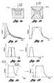
- FIG. 1 cshows such pulses.
- the ultrafast pulseshave durations on the order of fs (10-15 sec) to ps (10-12) and, at the decreased scale, exploit material properties at the atomic and molecular which are fundamentally different than found in the range of several hundred ps to ns.
- Laser systems for ultrafast pulse generationvary in complexity and are exemplary embodiments are described in U.S. Pat. Nos. 5,920,668 and 5,400,350, and in Ultrafast Lasers Escape The Lab”, PHOTONICS SPECTRA, July 1998, pp. 157-161.
- the embodimentsgenerally include methods for pulse stretching of mode locked ultrafast pulses prior to amplification to avoid amplifier saturation followed by compression to extremely narrow widths.
- This technologyholds promise for certain class of micromachining and possibly finer scale “nanomachining” operations, the latter benefit afforded by machining below diffraction limit.
- Applicanthas discovered practical limitations at the present time with the available power in each pulse for applications like metal link blowing and similar micromachining applications leading to the unacceptable requirement for multiple pulses.
- Metal reflectivitydecreases with increased power density of a laser pulse (ref. 1).
- the reflectivity of a metalis directly proportional to the free electron conductivity in a material.
- the collision time between electrons and the latticeis reduced. This shortening of the collision time reduces the conductivity and hence the reflectivity.
- the reflectivity of aluminumdecreases from 92% to less than 25% as the laser power densities increases to the range of 10 9 watts/cm 2 .
- Kis the thermal diffusivity of the material
- tis the length of the laser pulse.
- a short laser pulseprevents heat dissipating to the substrate below the melting link and also heat conducting laterally to the material contiguous to the link.
- the pulsemust be long enough to heat the link material all the way through.
- the target metal linkheats up and tries to expand.
- the oxide surrounding the linkcontains the expanding material.
- stressis built up within the oxide.
- the pressure of the expanding metalexceeds the yield point of the oxide and the oxide cracks and the metal link explodes into a fine particle vapor.
- the principal crack points of metal linkoccurs at the maximum stress points, which are at the edges of the link both top and bottom as shown in FIG. 1 b.
- Q-switched laser systemscan be modified to provide short pulses of various shapes.
- Typical prior art lasers that produce high peak power, short pulse lasersare standard Q-switched lasers. These lasers produce a temporal pulse having a moderate pulse rise time. It is possible to change this temporal shape by using a Pockels Cell pulse slicer that switch out sections of the laser beam.
- U.S. Pat. No. 4,483,005i.e., the '005 patent
- various methods for affecting (i.e., reducing) laser beam pulse widthare disclosed.
- the laser pulsecan be shaped somewhat to produce a “non-Gaussian” shaped beam by truncating energy outside the central lobe. It should be noted that if a relatively broad Q-switched waveform is to be transformed to a narrow, uniform shape, only a small fraction of the pulse energy will be used. For example, truncation of a Gaussian pulse to provide a sharp rise time and a narrow pulse with flatness to within 10% reduces the pulse energy by about 65%.
- FIG. 7shows the time interval for relatively flat laser power output.
- a desirable improvement over the prior artwould provide an efficient method for generating short pulses with high energy enclosure within the pulse duration with rapidly decaying tails.
- laser technologywhich produces pulse shapes different than those of the Q-switched pulse envelope is preferred.
- Such pulseshave fast rise time, uniform energy in the central lobe, and fast decay.
- the fast rise-time, high power density pulse as produced by a laser other than a standard Q-switched Nd:YAGwill best accomplish this task.
- a non-Gaussian, substantially rectangular pulse shapeis particularly advantageous for metal link processing where an overlying insulator exists.
- Applicants resultsshow that the fast rise time on the order of 1 ns, and preferably about 0.5 ns, provides a thermal shock to the overlying layer of oxide which facilitates the link blowing process.
- the reflectivityis reduced with the fast rising short pulse.
- a pulse duration of about 5 ns with a substantially uniform pulse shapeallows more energy to be coupled to the link leading to a reduced energy requirement for link removal. Rapid fall time of about 2 ns is important to eliminate the possibility of substrate damage.
- an advantage of a nearly square power density pulse in timeis that the power density is the highest when it is needed and the pulse is off when it is not.
- a short fast rising pulsewill allow the top of the link to melt and expand first before the heat can diffuse down to the lower portion of the link. Hence, stress is built up in the top of the link and promotes cracking of the top layer without generating a crack down to the substrate.
- State of the art fast pulse systemsincorporate gain switched technology, in which a low power semiconductor seed laser is rapidly and directly modulated to produce a controlled pulse shape which is subsequently amplified with a laser amplifier, such as a cladding pumped fiber optic system with a high power laser diode or diode array used as the pump laser.
- a laser amplifiersuch as a cladding pumped fiber optic system with a high power laser diode or diode array used as the pump laser.
- Such laser systemsare described in U.S. Pat. No. 5,694,408 and PCT Application No. PCT/U.S98/42050, and are “building blocks” of certain ultra-fast chirped pulse amplifier systems, for instance the system described in U.S. Pat. No. 5,400,350.
- a predetermined waveform shapeis generated from a gain-switched laser which is different than that of the standard Q-switched systems.
- the fast rising laser pulseis of sufficient pulse duration to efficiently heat and vaporize the material of each metallic target structure with relatively uniform power density during the ablation period, yet a rapid pulse fall time after the target material is vaporized avoids damage to surrounding and underlying structures.
- a laser pulseis generated to provide a substantially square pulse shape with pulse duration in the range of about 2-10 nanoseconds and a rise time of about 1 ns and preferably about 0.4 ns. Additionally, the pulse decay is to be rapid when switched off thereby allowing only a very small fraction of pulse energy to remain after the predetermined pulse duration, the pulse “tails” rapidly decaying to a sufficiently low level so as to avoid the possibility of damaging the underlying substrate or other non-target materials. A comparison of these pulses is illustrated in FIG. 2 .
- Such structuresare typically arranged in a manner where the width and spacing between the structures is about 1 micron or smaller and stacked in depth.
- the application of a short laser pulsecleanly ablates the target material, yet damage to surrounding materials caused by heat dissipation in either the lateral direction or damage to the underlying substrate below the target material is prevented.
- an energy-efficient, laser-based method for processing target material having a specified dimension in a microscopic region without causing undesirable changes in electrical or physical characteristics of material surrounding the target materialincludes generating a laser pulse train utilizing a laser having a wavelength at a repetition rate wherein each of the pulses of the pulse train has a predetermined shape.
- the methodthen includes optically amplifying the pulse train without significantly changing the predetermined shape of the pulses to obtain an amplified pulse train.
- Each of the amplified pulseshas a substantially square temporal power density distribution, a sharp rise time, a pulse duration and a fall time.
- the methodalso includes delivering and focusing at least a portion of the amplified pulse train into a spot on the target material wherein the rise time is fast enough to efficiently couple laser energy to the target material, the pulse duration is sufficient to process the target material and the fall time is rapid enough to prevent the undesirable changes to the material surrounding the target material.
- the target materialmay include microstructures such as conductive lines or links, the latter being common circuit elements of redundant semiconductor memories.
- the conductive linesmay be metal lines and wherein the pulse duration is sufficient to effectively heat and vaporize the metal lines, or a specified portion thereof.
- the target materialmay be a part of a semiconductor device such as a semiconductor memory having 16-256 megabits.
- At least a portion of the material surrounding the target materialmay be a substrate such as a semiconductor substrate.
- the target materialmay be part of a microelectronic device.
- the substantially square temporal power density distributionis sufficient to substantially completely ablate the target material.
- the rise timeis less than 1 nanosecond and, even more preferably, is less than 0.5 nanoseconds.
- the pulse durationis less than 10 nanoseconds and, even more preferably, is less than 5 nanoseconds.
- the fall timeis less than 2 nanoseconds.
- a single amplified pulseis typically sufficient to process the target material.
- the target materialmay have a reflectivity to the amplified pulses and wherein the power density of the amplified pulses is sufficiently high to reduce the reflectivity of the target material to the amplified pulses and to provide efficient coupling of the laser energy to the target material.
- each amplified pulsehas a relatively uniform power density distribution throughout the pulse duration.
- each pulsehas a temporal power density distribution uniform to within ten percent during the pulse duration.
- the material surrounding the target materialmay have optical properties, including absorption and polarization sensitivity, and thermal diffusivity properties different from the corresponding properties of the target material.
- the repetition rateis at least 1000 pulses/second and each of the amplified pulses has at least 0.1 and up to 3 microjoules of energy.
- the step of optically amplifyingprovides a gain of at least 20 DB.
- both the rise time and the fall timeare less than one-half of the pulse duration and wherein peak power of each amplified pulse is substantially constant between the rise and fall times.
- each of the amplified pulseshas a tail and the method also includes attenuating laser energy in the tails of the amplified pulses to reduce fall time of the amplified pulses while substantially maintaining the amount of power of the pulses.
- an energy-efficient system for processing target material having a specified dimension in a microscopic region without causing undesirable changes in electrical or physical characteristics of material surrounding the target materialincludes a controller for generating a processing control signal and a signal generator for generating a modulated drive waveform based on the processing control signal.
- the waveformhas a sub-nanosecond rise time.
- the systemalso includes a gain-switched, pulsed seed laser having a wavelength for generating a laser pulse train at a repetition rate.
- the drive waveformpumps the laser so that each pulse of the pulse train has a predetermined shape.
- the systemincludes a laser amplifier for optically amplifying the pulse train to obtain an amplified pulse train without significantly changing the predetermined shape of the pulses.
- Each of the amplified pulseshas a substantially square temporal power density distribution, a sharp rise time, a pulse duration and a fall time.
- the systemfurther includes a beam delivery and focusing subsystem for delivering and focusing at least a portion of the amplified pulse train onto the target material. The rise time is fast enough to efficiently couple laser energy to the target material, the pulse duration is sufficient to process the target material, and the fall time is rapid enough to prevent the undesirable changes to the material surrounding the target material.
- the laser amplifierpreferably includes an optical fiber and a pump such as a laser diode to pump the optical fiber wherein the pump is distinct from the seed laser.
- the laser diode pump sourcemay also be gain switched (pulsed and directly modulated) to increase diode lifetime by switching to the “off” state during extended periods where laser processing is not occurring.
- the seed laserincludes a laser diode.
- the systemmay include an attenuator for attenuating laser energy in the tails of the amplified pulses to reduce fall time of the amplified pulses while substantially maintaining the amount of energy of the pulses.
- the pulse durationmay be chosen as a function of a specified target material dimension.
- the specified material dimensionmay be less than the laser wavelength.
- the preferred laseris a high speed, semiconductor laser having a wavelength less than about 2 ⁇ m. Future material advances in semiconductor laser diode technology and fiber materials may provide for operation in the visible region as well as at longer infrared wavelengths.
- the seed laser diodemay be a multimode diode laser or a single frequency (single mode) laser utilizing a distributed Bragg reflector (DBR), distributed feedback (DFB), or an external cavity design.
- DBRdistributed Bragg reflector
- DFBdistributed feedback
- the spot sizetypically has a dimension in the range of about 1 ⁇ m-4 ⁇ m.
- the density of the memorymay be at least 16-256 megabits.
- the semiconductor devicemay be a microelectromechanical device.
- the attenuated laser energy in the pulse tailis attenuated by at least 10 dB within 1.5 times the pulse duration.
- an energy-efficient, laser-based method for ablating a metal link having a specified dimension embedded in at least one passivation layer without causing undesirable changes in electrical or physical characteristics of the at least one passivation layer surrounding the metal linkincludes generating a laser pulse train utilizing a laser having a wavelength at a repetition rate. Each of the pulses of the pulse train has a predetermined shape. The method also includes optically amplifying the pulse train without significantly changing the predetermined shape of the pulses to obtain an amplified pulse train. Each of the amplified pulses has a substantially square temporal power density distribution, a sharp rise time, a pulse duration and a fall time.
- the methodfurther includes delivering and focusing at least a portion of the amplified pulse train into a spot on the metal link.
- the rise timeis fast enough to efficiently couple laser energy to the metal link.
- the pulse durationis sufficient to ablate the metal link and the fall time is rapid enough to prevent the undesirable changes to the at least one passivation layer surrounding the metal link.
- an energy-efficient system for ablating a metal link having a specified dimension embedded in at least one passivation layer without causing undesirable changes in electrical or physical characteristics of the at least one passivation layer surrounding the metal linkincludes a controller for generating a processing control signal and a signal generator for generating a modulated drive waveform based on the processing control signal.
- the waveformhas a sub-nanosecond rise time.
- the systemalso includes a gain-switched, pulsed seed laser having a wavelength for generating a laser pulse train at a repetition rate.
- the drive waveformpumps the laser so that each pulse of the pulse train has a predetermined shape.
- the systemincludes a laser amplifier for optically amplifying the pulse train without significantly changing the predetermined shape of the pulses to obtain an amplified pulse train.
- Each of the amplified pulseshas a substantially square temporal power density distribution, a sharp rise time, a pulse duration and a fall time.
- the systemfurther includes a beam delivery and focusing subsystem for delivering and focusing at least a portion of the amplified pulse train into a spot on the metal link.
- the rise timeis fast enough to efficiently couple laser energy to the metal link.
- the pulse durationis sufficient to ablate the metal link, and the fall time is rapid enough to prevent the undesirable changes to the at least one passivation layer surrounding the metal link.
- the metal linkmay be embedded in a top passivation layer thereover and a bottom passivation layer thereunder.
- the pulse durationis sufficient to crack the top passivation layer but not the bottom passivation layer.
- a methodis provided to ablate target material using a laser having a wavelength suitable for laser material processing while avoiding damage to surrounding materials.
- the methodincludes the steps of modulating a laser beam to produce a predetermined gain-switched pulse and focusing the laser beam onto the target region.
- the predetermined gain-switched pulse shapeincludes a rise time of the laser pulse fast enough to efficiently couple laser energy to a target structure, with a pulse duration of sufficient length to efficiently heat and vaporize the target material, and a pulse decay time which is rapid enough to avoid damage of structures surrounding the target material.
- a system foris provided to ablate material using a laser having a wavelength suitable for laser processing while avoiding damage to surrounding materials.
- the systemincludes a laser source, components to modulate the laser source to generate a laser pulse having a predetermined gain-switched pulse shape, and optical components for focusing the laser beam onto the target region.
- the predetermined pulse shapeincludes an optical rise time of the laser pulse fast enough to efficiently couple laser energy to a target structure, with a pulse duration of sufficient length to efficiently heat and vaporize the target material, and a pulse decay time which is rapid enough to avoid damage of structures surrounding the target material.
- the gain-switched pulse shapeincludes a fast rise time pulse, substantially flat at the top, with a fast pulse fall time.
- a “seed” laser diodeis directly modulated to generate a predetermined pulse shape.
- the optical poweris increased through amplification with a fiber laser amplifier to output power levels sufficient for laser processing.
- the resulting gain-switched pulse at the fiber laser amplifier outputis focused onto the target region.
- the pulse temporal power distribution of the directly modulated seed diodeis modified to compensate for distortion or non-uniformity of the fiber amplifier or other components, for instance the “smooth” rise of an output modulator.
- the resulting laser processing pulse which is focused into the target regionwill have a desired shape: fast rise time, relatively flat during the pulse duration, with rapid decay.
- a “pulse slicing” modulewhich is used to attenuate laser energy remaining at the output of the laser processing system when the “seed” laser pulse is terminated, thereby preventing heating of sensitive structures not designated as target material after processing is complete.
- the “pulse slicing” techniqueis useful to attenuate the tail of either a modified pulse or a standard Q-switched pulse. This is illustrated in FIGS. 4 a and 4 b , wherein a log scale is provided in the vertical axis of FIG. 4 b.
- a laser pulseis shaped having a rise and fall time shorter than about one-half of the pulse duration and where the peak power is approximately constant between the rise and fall time.
- FIG. 1 ashows schematically stress cracks in a top surface layer only of a semiconductor caused by expanding vaporized metal
- FIG. 1 bshows schematically stress cracks in top and bottom layers of a semiconductor caused by expanding vaporized metal
- FIG. 1 cshows typical prior art laser pulses resembling a Gaussian shape, or a mixture of a Gaussian with an exponential tail, referred to as a “Q-switched pulse envelope”;
- FIG. 2shows the preferred pulse shape of the present invention for processing metal links when compared to a Q-switched of the same total energy
- FIGS. 3 a and 3 bshow a method of combining two short pulses closely spaced in time to create a modified pulse
- FIGS. 4 a and 4 bshow the result of “pulse slicing” for improving the pulse energy enclosure of a general pulse shape
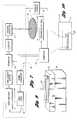
- FIG. 5is a general block diagram of a preferred laser system for laser material processing
- FIG. 6 ais a schematic diagram of one type of a MOPA laser system with a distributed Bragg laser as the semiconductor seed laser; this is a single mode laser and a fiber optic amplifier producing the preferred pulse shape;
- FIG. 6 bis a schematic diagram of a single frequency laser with external cavity tuning and a fiber optic amplifier
- FIG. 7is a block diagram schematic of another laser system of the present invention including a preferred attenuator and an optional shifter;
- FIG. 8is a graph of temperature at the interface between the silicon dioxide layer and the silicon substrate in FIG. 9, as a function of the thickness of the silicon dioxide layer;
- FIG. 9shows a perspective diagrammatic view of a link of a memory on its substrate
- FIG. 10is a drawing of a Gaussian laser beam focused onto a small spot on a focal plane containing a metal link emphasizing the microscopic size of the link compared to the diffraction-limited beam waist;
- FIGS. 11 a and 11 bare graphs which show the results of a computer finite element analysis simulation where the time history of stress and temperature is plotted in the graphs for a Q-switched pulse and square pulse used for metal link processing.
- a seed laser 10 and a fiber amplifierare mounted on a stable platform attached to the motion system 20 and the workpiece. It is very important in removing links that the beam be positioned with accuracy of less than ⁇ fraction (3/10) ⁇ of a micron.
- the timing of the laser pulse to correlate with the relative positions of the target and optical systemis important because of the continuous motion required in order to obtain high processing speeds.
- the laser 10is externally controlled by the computer 33 and a signal generator 11 and transmits its modulated beam to a focusing subsystem 12 comprising high numerical aperture optics and which may further comprise a beam deflector, for instance a galvonometer mirror controlled by a scanner control via the computer 33 .
- the system control computer 33is also operatively connected to a positioning mechanism or motion system 20 for the system and the signal generator 11 to properly time the pulse generation.
- the laser beammust be precisely controlled so as to produce a sharply focused beam, with a spot size in the range of about 1.5-4 microns, at the correct location in X, Y and Z.
- a step and repeat table 34can also be used to move a wafer 22 into position to treat each memory die 24 thereof.
- the substrate positioning mechanism 34may comprise very precise (well below 1 micron) X, Y, Z positioning mechanisms operating over a limited range of travel.
- the positioning mechanism 20may be used to translate the laser processing optical system components, including the laser, fiber amplifier, and focusing subsystem in a coarser fashion. Further details on a preferred positioning system are disclosed in the above-noted pending U.S. patent application entitled “High Speed Precision Positioning Apparatus”, Ser. No. 09/156,895, filed Sep. 18, 1998.
- a system optical switch 13 in the form of a further acousto-optic attenuator or pockels cellis positioned beyond the laser cavity, in the laser output beam. Under control of the computer 33 , it serves both to prevent the beam from reaching the focusing system except when desired, and, when the processing beam is required, to controllably reduce the power of the laser beam to the desired power level. During vaporization procedures this power level may be as little as 10 percent of the gross laser output, depending upon operating parameters of the system and process. The power level may be about 0.1 percent of the gross laser output during alignment procedures in which the laser output beam is aligned with the target structure prior to a vaporization procedure.
- the acousto-optic deviceis generally preferred because of the ease of use, although the delay of the pockels cell is considerably less.
- the positions of the wafer 22are controlled by the computer 33 .
- the relative movementis at substantially constant speed over the memory device 24 on the silicon wafer 22 , but step and repeat motion of the wafer is possible.
- the laser 10is controlled by timing signals based on the timing signals that control the motion system.
- the laser 10typically operates at a constant repetition rate and is synchronized to the positioning system by the system optical switch 13 .
- the laser beamis shown focused upon the wafer 22 .
- the laser beamis seen being focused on a link element 25 of a memory circuit or device 24 .
- spot size requirementsare becoming increasingly demanding.
- the spot size requirementis typically 1.5-4 microns in diameter, with peak power occurring in the center of the spot with good conformance to a Gaussian distribution, and with lower power occurring at the edges.
- Excellent beam qualityis needed, approaching diffraction limit, with a beam quality or “m-squared factor” of about 1.1 times or better typical.
- This “times diffraction limit” quality standardis well known to those skilled in the art of laser beam analysis.
- Low sidelobesare also preferred to avoid optical crosstalk and the undesirable illumination of features outside the target region.
- the link 25is somewhat smaller than the spot size, thereby mandating precision positioning and good spot quality.
- a linkmay be, for instance, 1 micron wide and about 1 ⁇ 3 micron thick.
- the linkis made of metal, and a lateral dimension (width) and thickness are smaller than the laser wavelength.
- a laser subsystem of FIG. 5utilizes a master oscillator, power amplifier (MOPA) configuration.
- MOPAmaster oscillator, power amplifier
- This systemproduces a laser pulse that seeds an amplifier to produce a high power short rise time pulse.
- a seed laseris the key to producing the fast rise time, short pulse but at very low energy levels.
- the systemrequires a laser amplifier to produce enough energy to do material processing.
- a fiber laser amplifier and a high-speed infrared laser diode having an output wavelength suitable for a laser processing applicationis preferred.
- a lasercan be devised that produces a laser pulse of the preferred shape and speed as shown in the lower part of FIG. 5 . That is, a fast rise time pulse, square at the top and a fast fall time.
- This pulse shapeprovides the desired laser-material interaction results of reduction in metal reflectivity, low diffusion of the energy into the device and cracking of the top oxide without damage to the lower oxide.
- the MOPA configurationis relatively new and pulsed versions are regarded as state of the art.
- the laser diodewhich has sub-nanosecond rise time in response to a modulating drive waveform is a starting point in the fiber laser MOPA configuration, with the laser diode as a gain element.
- the laser diodegenerally has multiple longitudinal modes and the sub-system can be configured for single mode operation or otherwise tuned with bulk components at the output or, alternatively, with integrated fiber gratings in the system.
- FIG. 6 bshows a schematic of a single frequency laser with external cavity tuning and also includes an optical fiber pumped at its cladding by diode laser pump.
- diode laser alternativesinclude distributed feedback lasers (DFB) and distributed Bragg lasers (DBL) which have integrated gratings and waveguide structures, some cases with external controls allowing the user to independently control the gain, phase, and grating filter. See FIG. 6 a for a DBL configuration including a coupler 50 .
- DBLdistributed Bragg lasers
- the laser frequenciescan be dynamically selected with a number of the configurations by adjustments of the bulk components, such as the grating and/or mirrors of the external cavity, or, alternatively, a fixed wavelength or mode chosen.
- the range over which the diode central wavelength can be selectedis impressive overall, from less than 1 ⁇ m to about 1.3-1.5 ⁇ m or longer, the latter wavelengths corresponding to those used for fiber optic communication.
- a key element for the purpose of this inventionis the rise time of the “seed” laser diode and the pulse shape.
- the seed laser wavelengthbe matched to the spectral band over which the fiber optic amplifier has high gain with little sensitivity to small wavelength changes—i.e., in the amplifier “flat” response region for maintaining excellent pulse-to-pulse power output with sufficient power.
- the gainis high in about a reasonably broad wavelength band near the 1.1 ⁇ m absorption edge of silicon.
- Further development in materials or integrated fiber componentsmay extend the useful wavelength regions providing more flexibility in matching the fiber emission spectrum, the seed laser wavelength and target material properties. For example, in Photonics Spectra , August 1997, p. 92, the results are reported for a state-of-the-art fiber laser development over a wavelength range of 1.1 ⁇ m to 1.7 ⁇ m.
- Raman shifterwas described in the above-noted '759 patent with the specific use with a short pulse Q-switched system. If desired this device could also be placed at the output of the fiber system to shift the output wavelength to a desirable region to improve absorption contrast, for example. Recognizing the importance of pulse width and small spot size requirements for processing, as taught in the above-noted '759 patent, typical operation of the preferred system for metal link processing will be in the range of about 1.06 ⁇ m or beyond, with a 1.08 ⁇ m wavelength, for example.
- the output of the seed laseris to be amplified for laser material processing.
- the preferred fiber optic laser amplifierwill provide gain of about 30 db.
- the seed laser outputis coupled to the core of the fiber laser either directly or with bulk optics which splits the beam for fiber delivery. Both techniques are routinely practiced by those skilled in the art of ultrafast lasers using chirped pulse amplification, but the system of the preferred embodiment is overall much less complex than such ultrafast systems.
- the seed pulseis amplified and no optics for pulse stretching and compression are required.
- the fiber used in the amplifier systemis cladding pumped with a diode laser having a substantially different wavelength than the seed laser, for example 980 nm, which allows for optical isolation of the seed and pumping beams with a dichroic mirror in the bulk optical system arrangement.
- the preferred arrangementutilizes a coupling arrangement where the seed laser is directly coupled to the fiber amplifier.
- the pump laserinjects the high power diode energy, say at 980 nm wavelength, into the cladding structure of a rare earth Ytterbium (Yb)-doped fiber using coupling techniques familiar to those skilled in the art of fiber laser system design.
- Low distortionis an important characteristic of the fiber amplifier. Low distortion allows the output pulse shape to substantially match the seed laser pulse shape or possibly further enhance the pulse edges or uniform power shape.
- the fiber optic gain mediumproduces the amplifier pulse of FIG. 5 which is delivered to the optical system and focused onto the object.
- Multiple fiber amplifierscan be cascaded for further gain if desired, provided the distortion is low. It could be advantageous to provide active optical switches or passive optical isolators at the output of intermediate stages to suppress spontaneous emission. These techniques are known by those skilled in the art and are disclosed in U.S. Pat. No. 5,400,350 and WO 98/92050, for example.
- a pulse sliceradded to the laser sub-system.
- Thismay be in the form of an electro optic device such as a pockels cell or preferably a low delay acousto-optic modulator.
- This techniquecan suppress energy in the pulse tails to negligible levels whenever the risk of damage occurs at a small multiple of the “pulse duration” of the processing pulse. For example, if the energy is reduced by 20 dB (100:1) within 1.5 times the predetermined pulse duration, there will be for all practical purposes no risk of substrate damage in metal link blowing applications.
- the low delay, high bandwidth pulse slicerwill be activated near the end of the amplifier pulse duration and will have a multiplicative effect on the pulse tail, with minimal distortion of the central lobe. Any effects of the amplifier distortion and the “turn on delay” of the modulator can be compensated to some degree by changing the shape of the seed diode laser waveform during the pulse duration. The resulting temporal pulse shape in the focused beam is compensated and is of the desired square shape.
- Modern techniques for effecting pulse widthinclude the use of modified output couplers, for instance, replacing conventional glass in Nd:YAG Q-switched lasers with GaAs, in either bulk or crystal form.
- Q-switched pules of duration from several picoseconds to a few nanosecondshave been reported in passive Q-switching of an Nd:YAG laser with a GaAs output coupler, OPTICAL ENGINEERING, 38(11), 1785-88, November 1999.
- the metal link 25is supported on the silicon substrate 30 by silicon dioxide insulator layer 32 , which may be, e.g., 0.3-0.5 microns thick.
- the silicon dioxideextends over the link, and often an additional insulating layer of silicon nitride is present over the SiO 2 layer.
- the laser beamimpinges on each link and heats it to the melting point. During the heating, the metal is prevented from vaporizing by the confining effect of the overlying passivation layers.
- the laser beamprogressively heats the metal, until the metal so expands that the insulator material ruptures. At this point, the molten material is under such high pressure that it instantly vaporizes and blows cleanly out through the rupture hole.
- the heatmay be considered to spread in essentially an exponential gradient by conduction from the portion of the beam striking the target.
- a peak beam powerso high that sufficient energy for evaporation of the link is delivered in a pulse of 8 nanoseconds, and preferably substantially less
- the conductive component of heat transfercan be substantially confined to a metal link and the underlying oxide layer, despite its being very thin, such that the temperature rise in the silicon attributable to conduction and the temperature rise attributable to absorption of the beam in silicon, can cumulatively be kept below the temperature threshold at which unacceptable silicon damage occurs.
- the above-noted '759 patentteaches several important aspects related to the thermal transfer characteristics of the link and adjacent structures.
- a thermal modelpredicts that narrow pulse widths, 3-10 ns, for example, which in turn are dependent upon the thickness of the target materials, are preferred to avoid heat conduction and subsequent damage to the Si substrate for representative dimensions.
- it is critically important to realize that other structures adjoining the linkcan also affect the quality of laser processing results, as the following experimental results indicate.
- the laser of choicewas a Ytterbium, cladding pumped fiber laser, in the MOPA configuration using a 980 nm pump diode and a 7 micron diameter single mode fiber.
- the 1.083 wavelengthis long enough to avoid substrate damage—about 10 times less absorption occurs at 1.083 ⁇ m compared to the 1.047 ⁇ m wavelength.
- the fast rising pulseprovides a thermal shock to the overlying layer of oxide which facilitates link removal.
- the high power density of the fast rising pulsereduces the link reflectivity which allows for efficient energy coupling.
- the stress and temperature historyindicate with certainty the importance of the fast rising pulse, with sub-nanosecond rise time. It is also known that if significant pulse energy is present, several nanoseconds after the ablation is completed, say at 15 ns, the Si can be damaged. A fast fall time, with a high extinction, is also important.
- the silicon substrateis also kept relatively cool both by appropriate selection of wavelength and by limiting the pulse duration, with a correspondingly square pulse with fast decay.
- the laser wavelength in this exampleis slightly less than the room temperature absorption edge of silicon (about 1.1 ⁇ m).
- the Raman shiftercould be utilized to shift the output wavelength beyond the absorption edge.
- another diode laser wavelengthcould potentially become commercially available for a MOPA configuration.
- Such wavelength selection and shifting techniquesmay advantageously be utilized in other laser processing and micromachining applications. In any case, by thus limiting the heating, it is possible to ensure that the silicon does not shift its absorption edge into the infrared and enter a thermal runaway condition in which silicon damage can occur.
- the specific embodiment of the MOPA configuration for fast pulse generation for cleanly blowing metal linksis taken as an example of pulse shaping and is provided to be illustrative rather than restrictive.
- excellent sub-nanosecond control over the pulse shapewas maintained, and found to be advantageous, including the possibility of fast compensation to correct the output pulse shape.
- Other applications in micromachining, marking, scribing, etc.could also benefit from precise, fast pulse control.
- the seed diodecould as easily be modulated with a “sawtooth” waveform or other non Q-switched waveshape for the purpose of creating or removing a specific feature on or within a surface.
Landscapes
- Physics & Mathematics (AREA)
- Optics & Photonics (AREA)
- Engineering & Computer Science (AREA)
- Mechanical Engineering (AREA)
- Plasma & Fusion (AREA)
- Computer Hardware Design (AREA)
- Microelectronics & Electronic Packaging (AREA)
- Power Engineering (AREA)
- General Physics & Mathematics (AREA)
- Condensed Matter Physics & Semiconductors (AREA)
- Manufacturing & Machinery (AREA)
- Lasers (AREA)
- Laser Beam Processing (AREA)
- Drying Of Semiconductors (AREA)
Abstract
Description

| Laser wavelength | 1.083 microns | ||
| 10 microjoules | |||
| Pulse width | 7 ns (FWHM, square pulse) | ||
| 10 KHz (70 KHz laser rate) | |||
| Spatial profile | Gaussian, TEM-OO, M2= | ||
| 1.02 (times diffraction limit) | |||
| Polarization | Unpolarized | ||
| Pulse Rise Time | ˜.5 ns | ||
| Model | ||
| 1 @ 0.7 uJ | Square Pulse | Slow Rise Pulse |
| 1st Crack | 929K @ 1.88 ns | 978K @ 2.40 ns |
| 2nd Crack | 1180K @ 2.93 ns | 1380K @ 3.45 ns |
| 3rd Crack | 1400K @ 2.05 ns | No |
| 4th Crack | 1520K @ 4.73 ns | No |
| Al thickness: 0.8 μm Al width: 0.8 μm | ||
| SiO2: 0.1 μm Si3N4: 0.4 μm | ||
| Laser energy: 0.7 uJ | ||
| Model | ||
| 2 @ 0.7 uJ | Square Pulse | Slow Rise Pulse |
| 1st Crack | 974K @ 2.03 ns | 1050K @ 2.55 ns |
| 2nd Crack | No | No |
| 3rd Crack | No | No |
| 4th Crack | No | No |
| Al thickness: 0.8 μm Al width: 0.8 μm | ||
| SiO2: 0.6 μm Si3N4: 0.6 μm | ||
| Laser energy: 0.7 uJ | ||
Claims (58)
Priority Applications (16)
| Application Number | Priority Date | Filing Date | Title |
|---|---|---|---|
| US09/941,389US6727458B2 (en) | 1999-12-28 | 2001-08-28 | Energy-efficient, laser-based method and system for processing target material |
| US10/683,086US7723642B2 (en) | 1999-12-28 | 2003-10-10 | Laser-based system for memory link processing with picosecond lasers |
| US10/683,147US20040134894A1 (en) | 1999-12-28 | 2003-10-10 | Laser-based system for memory link processing with picosecond lasers |
| US10/818,920US20040188399A1 (en) | 1999-12-28 | 2004-04-06 | Energy-efficient, laser-based method and system for processing target material |
| US11/003,885US20050092720A1 (en) | 1999-12-28 | 2004-12-03 | Laser-based method and system for memory link processing with picosecond lasers |
| US11/004,773US20050150880A1 (en) | 1999-12-28 | 2004-12-03 | Laser-based method and system for memory link processing with picosecond lasers |
| US11/003,104US20050115936A1 (en) | 1999-12-28 | 2004-12-03 | Laser-based method and system for memory link processing with picosecond lasers |
| US11/003,096US20050150879A1 (en) | 1999-12-28 | 2004-12-03 | Laser-based method and system for memory link processing with picosecond lasers |
| US11/004,191US20050115937A1 (en) | 1999-12-28 | 2004-12-03 | Laser-based method and system for memory link processing with picosecond lasers |
| US11/305,129US7582848B2 (en) | 1999-12-28 | 2005-12-19 | Energy-efficient, laser-based method and system for processing target material |
| US11/700,386US7838794B2 (en) | 1999-12-28 | 2007-01-31 | Laser-based method and system for removing one or more target link structures |
| US11/843,229US7750268B2 (en) | 1999-12-28 | 2007-08-22 | Energy efficient, laser-based method and system for processing target material |
| US11/969,264US20080105664A1 (en) | 1999-12-28 | 2008-01-04 | Energy-efficient, laser-based method and system for processing target material |
| US11/969,275US7679030B2 (en) | 1999-12-28 | 2008-01-04 | Energy-efficient, laser-based method and system for processing target material |
| US12/950,969US8253066B2 (en) | 1999-12-28 | 2010-11-19 | Laser-based method and system for removing one or more target link structures |
| US13/417,613US20120187098A1 (en) | 1999-12-28 | 2012-03-12 | Energy efficient, laser-based method and system for processing target material |
Applications Claiming Priority (2)
| Application Number | Priority Date | Filing Date | Title |
|---|---|---|---|
| US09/473,926US6281471B1 (en) | 1999-12-28 | 1999-12-28 | Energy-efficient, laser-based method and system for processing target material |
| US09/941,389US6727458B2 (en) | 1999-12-28 | 2001-08-28 | Energy-efficient, laser-based method and system for processing target material |
Related Parent Applications (3)
| Application Number | Title | Priority Date | Filing Date |
|---|---|---|---|
| US09/473,926ContinuationUS6281471B1 (en) | 1999-12-28 | 1999-12-28 | Energy-efficient, laser-based method and system for processing target material |
| US10/683,086ContinuationUS7723642B2 (en) | 1999-12-28 | 2003-10-10 | Laser-based system for memory link processing with picosecond lasers |
| US11/700,386ContinuationUS7838794B2 (en) | 1999-12-28 | 2007-01-31 | Laser-based method and system for removing one or more target link structures |
Related Child Applications (3)
| Application Number | Title | Priority Date | Filing Date |
|---|---|---|---|
| US10/683,147Continuation-In-PartUS20040134894A1 (en) | 1999-12-28 | 2003-10-10 | Laser-based system for memory link processing with picosecond lasers |
| US10/683,086Continuation-In-PartUS7723642B2 (en) | 1999-12-28 | 2003-10-10 | Laser-based system for memory link processing with picosecond lasers |
| US10/818,920ContinuationUS20040188399A1 (en) | 1999-12-28 | 2004-04-06 | Energy-efficient, laser-based method and system for processing target material |
Publications (2)
| Publication Number | Publication Date |
|---|---|
| US20020023901A1 US20020023901A1 (en) | 2002-02-28 |
| US6727458B2true US6727458B2 (en) | 2004-04-27 |
Family
ID=23881570
Family Applications (8)
| Application Number | Title | Priority Date | Filing Date |
|---|---|---|---|
| US09/473,926Expired - LifetimeUS6281471B1 (en) | 1999-12-28 | 1999-12-28 | Energy-efficient, laser-based method and system for processing target material |
| US09/941,389Expired - LifetimeUS6727458B2 (en) | 1999-12-28 | 2001-08-28 | Energy-efficient, laser-based method and system for processing target material |
| US10/818,920AbandonedUS20040188399A1 (en) | 1999-12-28 | 2004-04-06 | Energy-efficient, laser-based method and system for processing target material |
| US11/305,129Expired - Fee RelatedUS7582848B2 (en) | 1999-12-28 | 2005-12-19 | Energy-efficient, laser-based method and system for processing target material |
| US11/843,229Expired - Fee RelatedUS7750268B2 (en) | 1999-12-28 | 2007-08-22 | Energy efficient, laser-based method and system for processing target material |
| US11/969,275Expired - Fee RelatedUS7679030B2 (en) | 1999-12-28 | 2008-01-04 | Energy-efficient, laser-based method and system for processing target material |
| US11/969,264AbandonedUS20080105664A1 (en) | 1999-12-28 | 2008-01-04 | Energy-efficient, laser-based method and system for processing target material |
| US13/417,613AbandonedUS20120187098A1 (en) | 1999-12-28 | 2012-03-12 | Energy efficient, laser-based method and system for processing target material |
Family Applications Before (1)
| Application Number | Title | Priority Date | Filing Date |
|---|---|---|---|
| US09/473,926Expired - LifetimeUS6281471B1 (en) | 1999-12-28 | 1999-12-28 | Energy-efficient, laser-based method and system for processing target material |
Family Applications After (6)
| Application Number | Title | Priority Date | Filing Date |
|---|---|---|---|
| US10/818,920AbandonedUS20040188399A1 (en) | 1999-12-28 | 2004-04-06 | Energy-efficient, laser-based method and system for processing target material |
| US11/305,129Expired - Fee RelatedUS7582848B2 (en) | 1999-12-28 | 2005-12-19 | Energy-efficient, laser-based method and system for processing target material |
| US11/843,229Expired - Fee RelatedUS7750268B2 (en) | 1999-12-28 | 2007-08-22 | Energy efficient, laser-based method and system for processing target material |
| US11/969,275Expired - Fee RelatedUS7679030B2 (en) | 1999-12-28 | 2008-01-04 | Energy-efficient, laser-based method and system for processing target material |
| US11/969,264AbandonedUS20080105664A1 (en) | 1999-12-28 | 2008-01-04 | Energy-efficient, laser-based method and system for processing target material |
| US13/417,613AbandonedUS20120187098A1 (en) | 1999-12-28 | 2012-03-12 | Energy efficient, laser-based method and system for processing target material |
Country Status (7)
| Country | Link |
|---|---|
| US (8) | US6281471B1 (en) |
| EP (1) | EP1244534B1 (en) |
| JP (1) | JP5175416B2 (en) |
| KR (1) | KR100829008B1 (en) |
| DE (1) | DE60009348T2 (en) |
| TW (1) | TW478025B (en) |
| WO (1) | WO2001047659A1 (en) |
Cited By (73)
| Publication number | Priority date | Publication date | Assignee | Title |
|---|---|---|---|---|
| US20020167581A1 (en)* | 2001-03-29 | 2002-11-14 | Cordingley James J. | Methods and systems for thermal-based laser processing a multi-material device |
| US20030151053A1 (en)* | 2000-01-10 | 2003-08-14 | Yunlong Sun | Processing a memory link with a set of at least two laser pulses |
| US20030222330A1 (en)* | 2000-01-10 | 2003-12-04 | Yunlong Sun | Passivation processing over a memory link |
| US20030222324A1 (en)* | 2000-01-10 | 2003-12-04 | Yunlong Sun | Laser systems for passivation or link processing with a set of laser pulses |
| US20040009618A1 (en)* | 2002-03-27 | 2004-01-15 | Couch Bruce L. | Method and system for high-speed, precise micromachining an array of devices |
| US20040134896A1 (en)* | 1999-12-28 | 2004-07-15 | Bo Gu | Laser-based method and system for memory link processing with picosecond lasers |
| US20040134894A1 (en)* | 1999-12-28 | 2004-07-15 | Bo Gu | Laser-based system for memory link processing with picosecond lasers |
| US20040188399A1 (en)* | 1999-12-28 | 2004-09-30 | Gsi Lumonics Inc. | Energy-efficient, laser-based method and system for processing target material |
| US20040226925A1 (en)* | 2003-03-07 | 2004-11-18 | Bo Gu | Laser system and method for material processing with ultra fast lasers |
| US20050041976A1 (en)* | 2003-08-19 | 2005-02-24 | Yunlong Sun | Generating sets of tailored laser pulses |
| US20050199598A1 (en)* | 2000-05-16 | 2005-09-15 | Gsi Lumonics Corporation | Method and system for precisely positioning a waist of a material-processing laser beam to process microstructures within a laser-processing site |
| US20050218122A1 (en)* | 2004-03-31 | 2005-10-06 | Imra America, Inc. | Pulsed laser processing with controlled thermal and physical alterations |
| US20050254530A1 (en)* | 2004-05-14 | 2005-11-17 | Yunlong Sun | Multi-output harmonic laser and methods employing same |
| US20050274702A1 (en)* | 2004-06-15 | 2005-12-15 | Laserfacturing Inc. | Method and apparatus for dicing of thin and ultra thin semiconductor wafer using ultrafast pulse laser |
| US20060000814A1 (en)* | 2004-06-30 | 2006-01-05 | Bo Gu | Laser-based method and system for processing targeted surface material and article produced thereby |
| US20060039419A1 (en)* | 2004-08-16 | 2006-02-23 | Tan Deshi | Method and apparatus for laser trimming of resistors using ultrafast laser pulse from ultrafast laser oscillator operating in picosecond and femtosecond pulse widths |
| US20060043079A1 (en)* | 2003-05-16 | 2006-03-02 | The Regents Of The University Of California | Self-seeded single-frequency laser peening method |
| US20060108337A1 (en)* | 2004-11-11 | 2006-05-25 | Bo Gu | Method and system for laser soft marking |
| US20060128073A1 (en)* | 2004-12-09 | 2006-06-15 | Yunlong Sun | Multiple-wavelength laser micromachining of semiconductor devices |
| US20060126674A1 (en)* | 2004-12-09 | 2006-06-15 | Yunlong Sun | Lasers for synchronized pulse shape tailoring |
| US20060141681A1 (en)* | 2000-01-10 | 2006-06-29 | Yunlong Sun | Processing a memory link with a set of at least two laser pulses |
| US20060151704A1 (en)* | 2004-12-30 | 2006-07-13 | Cordingley James J | Laser-based material processing methods, system and subsystem for use therein for precision energy control |
| US20060169677A1 (en)* | 2005-02-03 | 2006-08-03 | Laserfacturing Inc. | Method and apparatus for via drilling and selective material removal using an ultrafast pulse laser |
| US20060189091A1 (en)* | 2004-11-11 | 2006-08-24 | Bo Gu | Method and system for laser hard marking |
| US20060191884A1 (en)* | 2005-01-21 | 2006-08-31 | Johnson Shepard D | High-speed, precise, laser-based material processing method and system |
| US20060235564A1 (en)* | 2005-04-18 | 2006-10-19 | Igor Troitski | Method and multifunctional system for producing laser-induced images on the surfaces of various materials and inside transparent materials |
| US20060256181A1 (en)* | 2005-05-11 | 2006-11-16 | Ehrmann Jonathan S | Optical scanning method and system and method for correcting optical aberrations introduced into the system by a beam deflector |
| US7150811B2 (en) | 2002-11-26 | 2006-12-19 | Pei Company | Ion beam for target recovery |
| US20070008611A1 (en)* | 2003-06-27 | 2007-01-11 | Imra America, Inc. | High power fiber chirped pulse amplification system utilizing telecom-type components |
| US20070031993A1 (en)* | 2002-05-17 | 2007-02-08 | Gsi Lumonics Corporation | Method and system for machine vision-based feature detection and mark verification in a workpiece or wafer marking system |
| US20070106416A1 (en)* | 2006-06-05 | 2007-05-10 | Griffiths Joseph J | Method and system for adaptively controlling a laser-based material processing process and method and system for qualifying same |
| US20070117227A1 (en)* | 2005-11-23 | 2007-05-24 | Gsi Group Corporation | Method And System for Iteratively, Selectively Tuning A Parameter Of A Doped Workpiece Using A Pulsed Laser |
| US20070173075A1 (en)* | 2001-03-29 | 2007-07-26 | Joohan Lee | Laser-based method and system for processing a multi-material device having conductive link structures |
| US20070178714A1 (en)* | 2002-03-27 | 2007-08-02 | Bo Gu | Method and system for high-speed precise laser trimming and scan lens for use therein |
| US20070199927A1 (en)* | 1999-12-28 | 2007-08-30 | Bo Gu | Laser-based method and system for removing one or more target link structures |
| US20070215575A1 (en)* | 2006-03-15 | 2007-09-20 | Bo Gu | Method and system for high-speed, precise, laser-based modification of one or more electrical elements |
| US20070248136A1 (en)* | 2006-04-19 | 2007-10-25 | Mobius Photonics, Inc. | Laser apparatus having multiple synchronous amplifiers tied to one master oscillator |
| US20070272667A1 (en)* | 2006-05-24 | 2007-11-29 | Weisheng Lei | Micromachining with short-pulsed, solid-state UV laser |
| US20080013163A1 (en)* | 2006-07-11 | 2008-01-17 | Mobius Photonics, Inc. | Light source with precisely controlled wavelength-converted average power |
| US20080056642A1 (en)* | 2006-09-01 | 2008-03-06 | Mobius Photonics, Inc. | Reducing thermal load on optical head |
| US20080067155A1 (en)* | 2006-09-15 | 2008-03-20 | Bo Gu | Method and system for laser processing targets of different types on a workpiece |
| US20080140060A1 (en)* | 2003-08-11 | 2008-06-12 | Raydiance, Inc. | Ablative material removal with a preset removal rate or volume or depth |
| US20080164240A1 (en)* | 2007-01-05 | 2008-07-10 | Gsi Group Corporation | System and method for multi-pulse laser processing |
| US20080240184A1 (en)* | 2007-03-27 | 2008-10-02 | Imra America, Inc. | Beam stabilized fiber laser |
| US20090010288A1 (en)* | 2007-07-05 | 2009-01-08 | Mobius Photonics, Inc. | Fiber mopa system without stimulated brillouin scattering |
| US7486705B2 (en) | 2004-03-31 | 2009-02-03 | Imra America, Inc. | Femtosecond laser processing system with process parameters, controls and feedback |
| US20090245302A1 (en)* | 2008-03-31 | 2009-10-01 | Electro Scientific Industries, Inc. | Methods and systems for dynamically generating tailored laser pulses |
| US20090246413A1 (en)* | 2008-03-27 | 2009-10-01 | Imra America, Inc. | Method for fabricating thin films |
| US20090246530A1 (en)* | 2008-03-27 | 2009-10-01 | Imra America, Inc. | Method For Fabricating Thin Films |
| US20100196192A1 (en)* | 2009-01-30 | 2010-08-05 | Imra America, Inc. | Production of metal and metal-alloy nanoparticles with high repetition rate ultrafast pulsed laser ablation in liquids |
| US20100246611A1 (en)* | 2009-03-27 | 2010-09-30 | Electro Scientific Industries, Inc. | Laser micromachining with tailored bursts of short laser pulses |
| US20100276405A1 (en)* | 2008-03-31 | 2010-11-04 | Electro Scientific Industries, Inc. | Laser systems and methods using triangular-shaped tailored laser pulses for selected target classes |
| US20110115129A1 (en)* | 2008-07-09 | 2011-05-19 | Fei Company | Method and Apparatus for Laser Machining |
| US20110193025A1 (en)* | 2010-02-10 | 2011-08-11 | Yuki Ichikawa | Production of fine particles of functional ceramic by using pulsed laser |
| US20110192714A1 (en)* | 2010-02-10 | 2011-08-11 | Bing Liu | Nanoparticle production in liquid with multiple-pulse ultrafast laser ablation |
| US20110192450A1 (en)* | 2010-02-10 | 2011-08-11 | Bing Liu | Method for producing nanoparticle solutions based on pulsed laser ablation for fabrication of thin film solar cells |
| US8084706B2 (en) | 2006-07-20 | 2011-12-27 | Gsi Group Corporation | System and method for laser processing at non-constant velocities |
| US8125704B2 (en) | 2008-08-18 | 2012-02-28 | Raydiance, Inc. | Systems and methods for controlling a pulsed laser by combining laser signals |
| US8135050B1 (en) | 2005-07-19 | 2012-03-13 | Raydiance, Inc. | Automated polarization correction |
| US8139910B2 (en) | 2006-01-23 | 2012-03-20 | Raydiance, Inc. | Systems and methods for control of ultra short pulse amplification |
| US8150271B1 (en) | 2006-03-28 | 2012-04-03 | Raydiance, Inc. | Active tuning of temporal dispersion in an ultrashort pulse laser system |
| US8173929B1 (en)* | 2003-08-11 | 2012-05-08 | Raydiance, Inc. | Methods and systems for trimming circuits |
| US8189971B1 (en) | 2006-01-23 | 2012-05-29 | Raydiance, Inc. | Dispersion compensation in a chirped pulse amplification system |
| US8232687B2 (en) | 2006-04-26 | 2012-07-31 | Raydiance, Inc. | Intelligent laser interlock system |
| WO2012092184A3 (en)* | 2010-12-28 | 2012-10-26 | Electro Scientific Industries, Inc. | Methods and systems for link processing using laser pulses with optimized temporal power profiles and polarizations |
| US8398622B2 (en) | 2003-05-20 | 2013-03-19 | Raydiance, Inc. | Portable optical ablation system |
| US8497449B1 (en) | 2006-05-26 | 2013-07-30 | Synchron Laser Service Inc. | Micro-machining of ceramics using an ytterbium fiber-laser |
| US8598490B2 (en) | 2008-03-31 | 2013-12-03 | Electro Scientific Industries, Inc. | Methods and systems for laser processing a workpiece using a plurality of tailored laser pulse shapes |
| US8884184B2 (en) | 2010-08-12 | 2014-11-11 | Raydiance, Inc. | Polymer tubing laser micromachining |
| US8921733B2 (en) | 2003-08-11 | 2014-12-30 | Raydiance, Inc. | Methods and systems for trimming circuits |
| US9022037B2 (en) | 2003-08-11 | 2015-05-05 | Raydiance, Inc. | Laser ablation method and apparatus having a feedback loop and control unit |
| US9054494B2 (en) | 2011-07-11 | 2015-06-09 | V Technology Co., Ltd. | Pulsed laser oscillator and method for controlling pulsed laser oscillation |
| US9114482B2 (en) | 2010-09-16 | 2015-08-25 | Raydiance, Inc. | Laser based processing of layered materials |
Families Citing this family (183)
| Publication number | Priority date | Publication date | Assignee | Title |
|---|---|---|---|---|
| US6987786B2 (en) | 1998-07-02 | 2006-01-17 | Gsi Group Corporation | Controlling laser polarization |
| US6865210B2 (en)* | 2001-05-03 | 2005-03-08 | Cymer, Inc. | Timing control for two-chamber gas discharge laser system |
| US6340806B1 (en)* | 1999-12-28 | 2002-01-22 | General Scanning Inc. | Energy-efficient method and system for processing target material using an amplified, wavelength-shifted pulse train |
| AU2001227764A1 (en) | 2000-01-10 | 2001-07-24 | Electro Scientific Industries, Inc. | Laser system and method for processing a memory link with a burst of laser pulses having ultrashort pulsewidths |
| TWI295491B (en)* | 2001-12-17 | 2008-04-01 | Electro Scient Ind Inc | Processing a memory link with a set of at least two laser pulses |
| US6555783B2 (en)* | 2000-02-03 | 2003-04-29 | Canon Kabushiki Kaisha | Laser processing method and laser processing apparatus |
| US6885683B1 (en)* | 2000-05-23 | 2005-04-26 | Imra America, Inc. | Modular, high energy, widely-tunable ultrafast fiber source |
| JP4320926B2 (en)* | 2000-06-16 | 2009-08-26 | パナソニック株式会社 | Laser drilling method and apparatus |
| WO2002005345A1 (en) | 2000-07-12 | 2002-01-17 | Electro Scientific Industries, Inc. | Uv laser system and method for single pulse severing of ic fuses |
| JP2002040627A (en)* | 2000-07-24 | 2002-02-06 | Nec Corp | Method for correcting laser pattern and apparatus for correcting the same |
| KR100343812B1 (en)* | 2000-09-21 | 2002-07-20 | 광주과학기술원 | Measurement system and the method for chromatic dispersion in optical fibers |
| US6664500B2 (en)* | 2000-12-16 | 2003-12-16 | Anadigics, Inc. | Laser-trimmable digital resistor |
| US6806440B2 (en) | 2001-03-12 | 2004-10-19 | Electro Scientific Industries, Inc. | Quasi-CW diode pumped, solid-state UV laser system and method employing same |
| US6781090B2 (en)* | 2001-03-12 | 2004-08-24 | Electro Scientific Industries, Inc. | Quasi-CW diode-pumped, solid-state harmonic laser system and method employing same |
| US6570704B2 (en)* | 2001-03-14 | 2003-05-27 | Northrop Grumman Corporation | High average power chirped pulse fiber amplifier array |
| US20050259709A1 (en) | 2002-05-07 | 2005-11-24 | Cymer, Inc. | Systems and methods for implementing an interaction between a laser shaped as a line beam and a film deposited on a substrate |
| US6927359B2 (en)* | 2001-06-14 | 2005-08-09 | Advanced Cardiovascular Systems, Inc. | Pulsed fiber laser cutting system for medical implants |
| US7065121B2 (en)* | 2001-07-24 | 2006-06-20 | Gsi Group Ltd. | Waveguide architecture, waveguide devices for laser processing and beam control, and laser processing applications |
| US7464847B2 (en)* | 2005-06-03 | 2008-12-16 | Tyco Healthcare Group Lp | Surgical stapler with timer and feedback display |
| US10285694B2 (en) | 2001-10-20 | 2019-05-14 | Covidien Lp | Surgical stapler with timer and feedback display |
| DE10203198B4 (en)* | 2002-01-21 | 2009-06-10 | Carl Zeiss Meditec Ag | Method for material processing with laser pulses of large spectral bandwidth and apparatus for carrying out the method |
| US7358157B2 (en)* | 2002-03-27 | 2008-04-15 | Gsi Group Corporation | Method and system for high-speed precise laser trimming, scan lens system for use therein and electrical device produced thereby |
| US20060199354A1 (en)* | 2002-03-27 | 2006-09-07 | Bo Gu | Method and system for high-speed precise laser trimming and electrical device produced thereby |
| US20040017431A1 (en)* | 2002-07-23 | 2004-01-29 | Yosuke Mizuyama | Laser processing method and laser processing apparatus using ultra-short pulse laser |
| US7259906B1 (en) | 2002-09-03 | 2007-08-21 | Cheetah Omni, Llc | System and method for voice control of medical devices |
| JP4244611B2 (en)* | 2002-10-22 | 2009-03-25 | パナソニック株式会社 | Drilling method of ceramic green sheet |
| JP2004200221A (en)* | 2002-12-16 | 2004-07-15 | Toray Eng Co Ltd | Laser marking method and device thereof |
| US7217941B2 (en) | 2003-04-08 | 2007-05-15 | Cymer, Inc. | Systems and methods for deflecting plasma-generated ions to prevent the ions from reaching an internal component of an EUV light source |
| WO2004098003A1 (en)* | 2003-04-29 | 2004-11-11 | Southampton Photonics Limited | Laser apparatus for material processing |
| US7277188B2 (en) | 2003-04-29 | 2007-10-02 | Cymer, Inc. | Systems and methods for implementing an interaction between a laser shaped as a line beam and a film deposited on a substrate |
| US20040231481A1 (en) | 2003-05-23 | 2004-11-25 | Floding Daniel Leonard | Apparatus for perforating or slitting heat shrink film |
| ATE402888T1 (en)* | 2003-06-23 | 2008-08-15 | Bridgestone Firestone North Am | METHOD AND SYSTEM FOR MARKING TIRES |
| US6947454B2 (en)* | 2003-06-30 | 2005-09-20 | Electro Scientific Industries, Inc. | Laser pulse picking employing controlled AOM loading |
| DE10333770A1 (en)* | 2003-07-22 | 2005-02-17 | Carl Zeiss Meditec Ag | Method for material processing with laser pulses of large spectral bandwidth and apparatus for carrying out the method |
| US7364952B2 (en)* | 2003-09-16 | 2008-04-29 | The Trustees Of Columbia University In The City Of New York | Systems and methods for processing thin films |
| US7823366B2 (en)* | 2003-10-07 | 2010-11-02 | Douglas Machine, Inc. | Apparatus and method for selective processing of materials with radiant energy |
| JP2005217209A (en)* | 2004-01-30 | 2005-08-11 | Hitachi Ltd | Laser annealing method and laser annealing apparatus |
| WO2005094275A2 (en) | 2004-03-25 | 2005-10-13 | Imra America, Inc. | Optical parametric amplification, optical parametric generation, and optical pumping in optical fibers systems |
| WO2011123205A1 (en) | 2010-03-30 | 2011-10-06 | Imra America, Inc. | Laser-based material processing apparatus and methods |
| US7505196B2 (en)* | 2004-03-31 | 2009-03-17 | Imra America, Inc. | Method and apparatus for controlling and protecting pulsed high power fiber amplifier systems |
| US7282666B2 (en)* | 2004-05-07 | 2007-10-16 | Micron Technology, Inc. | Method and apparatus to increase throughput of processing using pulsed radiation sources |
| DE102004024475A1 (en)* | 2004-05-14 | 2005-12-01 | Lzh Laserzentrum Hannover E.V. | Method and device for separating semiconductor materials |
| US7352784B2 (en)* | 2004-07-20 | 2008-04-01 | Jds Uniphase Corporation | Laser burst boosting method and apparatus |
| JP2006128157A (en)* | 2004-10-26 | 2006-05-18 | Komatsu Ltd | Driver laser system for extreme ultraviolet light source |
| US7422988B2 (en) | 2004-11-12 | 2008-09-09 | Applied Materials, Inc. | Rapid detection of imminent failure in laser thermal processing of a substrate |
| US7910499B2 (en)* | 2004-11-12 | 2011-03-22 | Applied Materials, Inc. | Autofocus for high power laser diode based annealing system |
| US7129440B2 (en)* | 2004-11-12 | 2006-10-31 | Applied Materials, Inc. | Single axis light pipe for homogenizing slow axis of illumination systems based on laser diodes |
| US7438468B2 (en)* | 2004-11-12 | 2008-10-21 | Applied Materials, Inc. | Multiple band pass filtering for pyrometry in laser based annealing systems |
| US20060114948A1 (en)* | 2004-11-29 | 2006-06-01 | Lo Ho W | Workpiece processing system using a common imaged optical assembly to shape the spatial distributions of light energy of multiple laser beams |
| US20060159138A1 (en)* | 2004-12-21 | 2006-07-20 | Institut National D'optique | Pulsed laser light source |
| KR100672830B1 (en)* | 2005-03-21 | 2007-01-22 | 삼성전자주식회사 | Label marking method and label marking device using the same |
| US11291443B2 (en) | 2005-06-03 | 2022-04-05 | Covidien Lp | Surgical stapler with timer and feedback display |
| CA2609970C (en) | 2005-06-03 | 2014-08-12 | Tyco Healthcare Group Lp | Battery powered surgical instrument |
| US7365349B2 (en) | 2005-06-27 | 2008-04-29 | Cymer, Inc. | EUV light source collector lifetime improvements |
| US7180083B2 (en) | 2005-06-27 | 2007-02-20 | Cymer, Inc. | EUV light source collector erosion mitigation |
| US7141806B1 (en) | 2005-06-27 | 2006-11-28 | Cymer, Inc. | EUV light source collector erosion mitigation |
| US7539231B1 (en) | 2005-07-15 | 2009-05-26 | Lockheed Martin Corporation | Apparatus and method for generating controlled-linewidth laser-seed-signals for high-powered fiber-laser amplifier systems |
| US7135392B1 (en) | 2005-07-20 | 2006-11-14 | Applied Materials, Inc. | Thermal flux laser annealing for ion implantation of semiconductor P-N junctions |
| US7245419B2 (en)* | 2005-09-22 | 2007-07-17 | Raydiance, Inc. | Wavelength-stabilized pump diodes for pumping gain media in an ultrashort pulsed laser system |
| US7317179B2 (en) | 2005-10-28 | 2008-01-08 | Cymer, Inc. | Systems and methods to shape laser light as a homogeneous line beam for interaction with a film deposited on a substrate |
| US7679029B2 (en) | 2005-10-28 | 2010-03-16 | Cymer, Inc. | Systems and methods to shape laser light as a line beam for interaction with a substrate having surface variations |
| US7453077B2 (en) | 2005-11-05 | 2008-11-18 | Cymer, Inc. | EUV light source |
| EP1806203A1 (en)* | 2006-01-10 | 2007-07-11 | Siemens Aktiengesellschaft | Method of producing a hole |
| US9130344B2 (en) | 2006-01-23 | 2015-09-08 | Raydiance, Inc. | Automated laser tuning |
| WO2007096487A1 (en)* | 2006-02-23 | 2007-08-30 | Picodeon Ltd Oy | Semiconductor and an arrangement and a method for producing a semiconductor |
| US7602853B2 (en)* | 2006-04-17 | 2009-10-13 | Mediatek Inc. | Method and apparatus for channel estimation |
| US20070272666A1 (en)* | 2006-05-25 | 2007-11-29 | O'brien James N | Infrared laser wafer scribing using short pulses |
| JP2009545177A (en)* | 2006-07-27 | 2009-12-17 | エレクトロ サイエンティフィック インダストリーズ インコーポレーテッド | Tandem optical amplifier |
| US7674999B2 (en)* | 2006-08-23 | 2010-03-09 | Applied Materials, Inc. | Fast axis beam profile shaping by collimation lenslets for high power laser diode based annealing system |
| US7659187B2 (en)* | 2006-11-03 | 2010-02-09 | Applied Materials, Inc. | Method of forming PN junctions including a post-ion implant dynamic surface anneal process with minimum interface trap density at the gate insulator-silicon interface |
| US7431188B1 (en) | 2007-03-15 | 2008-10-07 | Tyco Healthcare Group Lp | Surgical stapling apparatus with powered articulation |
| US8800837B2 (en) | 2007-04-13 | 2014-08-12 | Covidien Lp | Powered surgical instrument |
| US7950560B2 (en) | 2007-04-13 | 2011-05-31 | Tyco Healthcare Group Lp | Powered surgical instrument |
| US11259801B2 (en) | 2007-04-13 | 2022-03-01 | Covidien Lp | Powered surgical instrument |
| US20080255413A1 (en) | 2007-04-13 | 2008-10-16 | Michael Zemlok | Powered surgical instrument |
| DE102007018402A1 (en)* | 2007-04-17 | 2008-10-23 | Panasonic Electric Works Europe Ag | Method for introducing a structure into a surface of a transparent workpiece |
| US7823760B2 (en) | 2007-05-01 | 2010-11-02 | Tyco Healthcare Group Lp | Powered surgical stapling device platform |
| US7931660B2 (en) | 2007-05-10 | 2011-04-26 | Tyco Healthcare Group Lp | Powered tacker instrument |
| CA2688771A1 (en)* | 2007-05-18 | 2008-11-27 | Gsi Group Corporation | Laser processing of conductive links |
| US8026158B2 (en)* | 2007-06-01 | 2011-09-27 | Electro Scientific Industries, Inc. | Systems and methods for processing semiconductor structures using laser pulses laterally distributed in a scanning window |
| US8076605B2 (en)* | 2007-06-25 | 2011-12-13 | Electro Scientific Industries, Inc. | Systems and methods for adapting parameters to increase throughput during laser-based wafer processing |
| KR101310243B1 (en)* | 2007-09-19 | 2013-09-24 | 지에스아이 그룹 코포레이션 | Link processing with high speed beam deflection |
| US7922063B2 (en) | 2007-10-31 | 2011-04-12 | Tyco Healthcare Group, Lp | Powered surgical instrument |
| US9498845B2 (en) | 2007-11-08 | 2016-11-22 | Applied Materials, Inc. | Pulse train annealing method and apparatus |
| US7903326B2 (en) | 2007-11-30 | 2011-03-08 | Radiance, Inc. | Static phase mask for high-order spectral phase control in a hybrid chirped pulse amplifier system |
| US7947599B2 (en)* | 2008-01-23 | 2011-05-24 | International Business Machines Corporation | Laser annealing for 3-D chip integration |
| WO2009117451A1 (en)* | 2008-03-21 | 2009-09-24 | Imra America, Inc. | Laser-based material processing methods and systems |
| WO2009137182A2 (en) | 2008-03-31 | 2009-11-12 | Electro Scientific Industries, Inc. | Combining multiple laser beams to form high repetition rate, high average power polarized laser beam |
| GB2459669A (en)* | 2008-04-30 | 2009-11-04 | Xsil Technology Ltd | Dielectric layer pulsed laser scribing and metal layer and semiconductor wafer dicing |
| DE102008028037A1 (en)* | 2008-06-12 | 2009-12-31 | Fraunhofer-Gesellschaft zur Förderung der angewandten Forschung e.V. | Method for generating pulsed laser radiation with a fiber laser |
| US8238390B2 (en)* | 2008-06-27 | 2012-08-07 | Institut National D'optique | Methods for stabilizing the output of a pulsed laser system having pulse shaping capabilities |
| WO2009155712A1 (en)* | 2008-06-27 | 2009-12-30 | Institut National D'optique | Digital laser pulse shaping module and system |
| JP5589318B2 (en)* | 2008-08-11 | 2014-09-17 | 住友電気工業株式会社 | Laser marking method |
| US9001172B2 (en) | 2008-09-04 | 2015-04-07 | Vardex Laser Solutions, Inc. | System for laser-based digital marking of objects with images or digital image projection with the laser beam shaped and amplified to have uniform irradiance distribution over the beam cross-section |
| US7813389B2 (en)* | 2008-11-10 | 2010-10-12 | Electro Scientific Industries, Inc. | Generating laser pulses of prescribed pulse shapes programmed through combination of separate electrical and optical modulators |
| US20100140238A1 (en)* | 2008-12-10 | 2010-06-10 | Continental Disc Corporation | Machining score lines in a rupture disc using laser machining |
| US8309885B2 (en)* | 2009-01-15 | 2012-11-13 | Electro Scientific Industries, Inc. | Pulse temporal programmable ultrafast burst mode laser for micromachining |
| US8821514B2 (en) | 2009-06-08 | 2014-09-02 | Covidien Lp | Powered tack applier |
| JP5473414B2 (en)* | 2009-06-10 | 2014-04-16 | 株式会社ディスコ | Laser processing equipment |
| KR20120098623A (en)* | 2009-09-24 | 2012-09-05 | 이에스아이-파이로포토닉스 레이저스, 인코포레이티드 | Method and apparatus to scribe a line in a thin film material using a burst of laser pulses with beneficial pulse shape |
| US8890025B2 (en) | 2009-09-24 | 2014-11-18 | Esi-Pyrophotonics Lasers Inc. | Method and apparatus to scribe thin film layers of cadmium telluride solar cells |
| KR20120116948A (en)* | 2009-11-30 | 2012-10-23 | 이에스아이-파이로포토닉스 레이저스, 인코포레이티드 | Method and apparatus for scribing a line in a thin film using a series of laser pulses |
| KR20120113245A (en)* | 2009-12-30 | 2012-10-12 | 지에스아이 그룹 코포레이션 | Link processing with high speed beam deflection |
| US8263903B2 (en) | 2010-05-18 | 2012-09-11 | Institut National D'optique | Method for stablizing an output of a pulsed laser system using pulse shaping |
| US20120033212A1 (en)* | 2010-07-09 | 2012-02-09 | Los Alamos National Security, Llc | Laser induced breakdown spectroscopy instrumentation for real-time elemental analysis |
| JP5075951B2 (en)* | 2010-07-16 | 2012-11-21 | ギガフォトン株式会社 | Extreme ultraviolet light source device and driver laser system |
| TWI393602B (en)* | 2010-08-04 | 2013-04-21 | Hortek Crystal Co Ltd | Laser process manufacturer |
| US9570874B1 (en) | 2010-08-10 | 2017-02-14 | Vardex Laser Solutions, Llc | System for laser-based digital marking of objects with images or digital image projection with the laser beam shaped and amplified to have uniform irradiance distribution over the beam cross-section |
| US8571077B2 (en) | 2010-08-31 | 2013-10-29 | First Solar, Inc. | System and method for laser modulation |
| GB201014778D0 (en) | 2010-09-06 | 2010-10-20 | Baird Brian W | Picosecond laser beam shaping assembly and a method of shaping a picosecond laser beam |
| US8556511B2 (en) | 2010-09-08 | 2013-10-15 | Abbott Cardiovascular Systems, Inc. | Fluid bearing to support stent tubing during laser cutting |
| DE102011014162B4 (en) | 2011-03-16 | 2019-12-05 | Berliner Glas Kgaa Herbert Kubatz Gmbh & Co | Method for producing a carrier of an electrostatic clamp |
| US20120250707A1 (en)* | 2011-03-31 | 2012-10-04 | Electro Scientific Industries, Inc. | Stabilization of pulsed mode seed lasers |
| JP2012213802A (en)* | 2011-04-01 | 2012-11-08 | Esi-Pyrophotonics Lasers Inc | Method and apparatus for scribing thin film layer of cadmium telluride solar cell |
| KR102138223B1 (en) | 2011-07-05 | 2020-07-28 | 일렉트로 싸이언티픽 인더스트리이즈 인코포레이티드 | Systems and methods for providing temperature stability of acousto-optic beam deflectors and acousto-optic modulators during use |
| JP5923884B2 (en)* | 2011-07-14 | 2016-05-25 | 株式会社ブイ・テクノロジー | Pulse laser oscillator |
| JP5923885B2 (en)* | 2011-07-14 | 2016-05-25 | 株式会社ブイ・テクノロジー | Pulse laser oscillator and pulse laser oscillation control method |
| CN102299201A (en)* | 2011-08-25 | 2011-12-28 | 上海市激光技术研究所 | Laser processing method for front electrode of solar cell and device |
| JP6189307B2 (en) | 2011-10-12 | 2017-08-30 | イムラ アメリカ インコーポレイテッド | Apparatus for high contrast optical signal transmission and exemplary applications |
| JP5910075B2 (en)* | 2011-12-27 | 2016-04-27 | 三星ダイヤモンド工業株式会社 | Workpiece processing method |
| CN103212784A (en)* | 2012-01-19 | 2013-07-24 | 昆山思拓机器有限公司 | Rapid processing method for laser Punch |
| US9155140B2 (en) | 2012-06-07 | 2015-10-06 | Gabriel Yavor | Optical waveform generator |
| US9205610B1 (en)* | 2012-09-17 | 2015-12-08 | Corning Cable Systems Llc | Head-on laser shaping of optical surfaces of optical fibers, and related assemblies and methods |
| US10660526B2 (en) | 2012-12-31 | 2020-05-26 | Omni Medsci, Inc. | Near-infrared time-of-flight imaging using laser diodes with Bragg reflectors |
| EP2938259A4 (en) | 2012-12-31 | 2016-08-17 | Omni Medsci Inc | Near-infrared lasers for non-invasive monitoring of glucose, ketones, hba1c, and other blood constituents |
| CA2895982A1 (en) | 2012-12-31 | 2014-07-03 | Omni Medsci, Inc. | Short-wave infrared super-continuum lasers for early detection of dental caries |
| US12193790B2 (en) | 2012-12-31 | 2025-01-14 | Omni Medsci, Inc. | Wearable devices comprising semiconductor diode light sources with improved signal-to-noise ratio |
| US9993159B2 (en) | 2012-12-31 | 2018-06-12 | Omni Medsci, Inc. | Near-infrared super-continuum lasers for early detection of breast and other cancers |
| WO2014143276A2 (en) | 2012-12-31 | 2014-09-18 | Omni Medsci, Inc. | Short-wave infrared super-continuum lasers for natural gas leak detection, exploration, and other active remote sensing applications |
| US9500634B2 (en) | 2012-12-31 | 2016-11-22 | Omni Medsci, Inc. | Short-wave infrared super-continuum lasers for natural gas leak detection, exploration, and other active remote sensing applications |
| US9478931B2 (en) | 2013-02-04 | 2016-10-25 | Nlight Photonics Corporation | Method for actively controlling the optical output of a seed laser |
| US9776277B2 (en)* | 2013-03-15 | 2017-10-03 | Electro Scientific Industries, Inc. | Phased array steering apparatus for laser beam positioning systems |
| US9263855B2 (en)* | 2013-03-15 | 2016-02-16 | Nlight Photonics Corporation | Injection locking of gain switched diodes for spectral narrowing and jitter stabilization |
| US9506869B2 (en) | 2013-10-16 | 2016-11-29 | Tsi, Incorporated | Handheld laser induced breakdown spectroscopy device |
| US9343307B2 (en) | 2013-12-24 | 2016-05-17 | Ultratech, Inc. | Laser spike annealing using fiber lasers |
| CN105119134A (en) | 2014-03-13 | 2015-12-02 | 恩耐激光技术有限公司 | Algorithms for rapid gating of seed suspendable pulsed fiber laser amplifiers |
| US10632568B2 (en)* | 2015-06-10 | 2020-04-28 | Ipg Photonics Corporation | Laser beam energy modification to reduce back-wall strikes during laser drilling |
| US9806488B2 (en) | 2015-06-30 | 2017-10-31 | Nlight, Inc. | Adaptive boost control for gating picosecond pulsed fiber lasers |
| TWI607814B (en)* | 2015-10-28 | 2017-12-11 | 新代科技股份有限公司 | Flying Laser Marking System with Real-time 3D Modeling and Method Thereof |
| CN106670653A (en)* | 2015-11-11 | 2017-05-17 | 恩耐公司 | Rust free stainless steel engraving |
| JP6666173B2 (en)* | 2016-03-09 | 2020-03-13 | 株式会社ディスコ | Laser processing equipment |
| US11025031B2 (en) | 2016-11-29 | 2021-06-01 | Leonardo Electronics Us Inc. | Dual junction fiber-coupled laser diode and related methods |
| JP6961583B2 (en)* | 2016-12-09 | 2021-11-05 | 古河電気工業株式会社 | Control method of pulse laser device, processing device and pulse laser device |
| US10193299B2 (en) | 2017-03-30 | 2019-01-29 | Datalogic Ip Tech S.R.L. | Modulation suppression in fiber lasers and associated devices |
| US11311295B2 (en) | 2017-05-15 | 2022-04-26 | Covidien Lp | Adaptive powered stapling algorithm with calibration factor |
| EP3652907A4 (en)* | 2017-07-12 | 2021-04-07 | Cohere Technologies, Inc. | DATA MODULATION SCHEMES BASED ON ZAK TRANSFORMATION |
| JP7039922B2 (en)* | 2017-10-16 | 2022-03-23 | 株式会社島津製作所 | Laser processing equipment |
| US12185949B2 (en) | 2017-10-30 | 2025-01-07 | Covidien Lp | Apparatus for endoscopic procedures |
| US10987104B2 (en) | 2017-10-30 | 2021-04-27 | Covidien Lp | Apparatus for endoscopic procedures |
| US11207066B2 (en) | 2017-10-30 | 2021-12-28 | Covidien Lp | Apparatus for endoscopic procedures |
| WO2019100067A1 (en)* | 2017-11-20 | 2019-05-23 | Ipg Photonics Corporation | System and method laser for processing of materials |
| WO2019183445A1 (en)* | 2018-03-23 | 2019-09-26 | Lawrence Livermore National Security, Llc | Laser drilling and machining enhancement using gated cw and short pulsed lasers |
| CN108393589A (en)* | 2018-04-25 | 2018-08-14 | 上海西邦电气有限公司 | A kind of sighting device and application method of laser obstacle eliminating system |
| AU2019203404B2 (en) | 2018-05-15 | 2024-11-07 | Howmedica Osteonics Corp. | Fabrication of components using shaped energy beam profiles |
| US11497490B2 (en) | 2018-07-09 | 2022-11-15 | Covidien Lp | Powered surgical devices including predictive motor control |
| US12137902B2 (en) | 2018-07-25 | 2024-11-12 | Covidien Lp | Adaptive anti-twitch algorithm for powered surgical devices |
| EP3837743A4 (en)* | 2018-08-13 | 2022-05-18 | Leonardo Electronics US Inc. | USING A METAL-CORE Printed Circuit Board (PCB) TO CREATE AN ULTRA-THIN, HIGH-CURRENT PULSE DRIVER |
| US11056854B2 (en) | 2018-08-14 | 2021-07-06 | Leonardo Electronics Us Inc. | Laser assembly and related methods |
| US11197734B2 (en) | 2018-10-30 | 2021-12-14 | Covidien Lp | Load sensing devices for use in surgical instruments |
| US11369372B2 (en) | 2018-11-28 | 2022-06-28 | Covidien Lp | Surgical stapler adapter with flexible cable assembly, flexible fingers, and contact clips |
| US11296481B2 (en) | 2019-01-09 | 2022-04-05 | Leonardo Electronics Us Inc. | Divergence reshaping array |
| US11202635B2 (en) | 2019-02-04 | 2021-12-21 | Covidien Lp | Programmable distal tilt position of end effector for powered surgical devices |
| US11376006B2 (en) | 2019-02-06 | 2022-07-05 | Covidien Lp | End effector force measurement with digital drive circuit |
| US11219461B2 (en) | 2019-03-08 | 2022-01-11 | Covidien Lp | Strain gauge stabilization in a surgical device |
| US11752571B1 (en) | 2019-06-07 | 2023-09-12 | Leonardo Electronics Us Inc. | Coherent beam coupler |
| EP3792683A1 (en) | 2019-09-16 | 2021-03-17 | Leonardo Electronics US Inc. | Asymmetric input intensity hexagonal homogenizer |
| JP7569564B2 (en)* | 2019-09-19 | 2024-10-18 | 大学共同利用機関法人自然科学研究機構 | Laser device and pulse width changing method |
| US11458244B2 (en) | 2020-02-07 | 2022-10-04 | Covidien Lp | Irrigating surgical apparatus with positive pressure fluid |
| US11553913B2 (en) | 2020-02-11 | 2023-01-17 | Covidien Lp | Electrically-determining tissue cut with surgical stapling apparatus |
| DE102020104907A1 (en)* | 2020-02-25 | 2021-08-26 | Berliner Glas GmbH | Process for the production of a component by atomic diffusion bonding |
| US12029470B2 (en) | 2020-05-21 | 2024-07-09 | Covidien Lp | Simultaneous RF monopolar calibration using a shared return electrode |
| US11622768B2 (en) | 2020-07-13 | 2023-04-11 | Covidien Lp | Methods and structure for confirming proper assembly of powered surgical stapling systems |
| US12193884B2 (en) | 2020-11-17 | 2025-01-14 | Covidien Lp | Contactless force measurement of motor torque in powered surgical device |
| US11653919B2 (en) | 2020-11-24 | 2023-05-23 | Covidien Lp | Stapler line reinforcement continuity |
| US11744580B2 (en) | 2020-11-24 | 2023-09-05 | Covidien Lp | Long stapler reloads with continuous cartridge |
| US12016556B2 (en) | 2021-05-03 | 2024-06-25 | Covidien Lp | Handheld electromechanical surgical system |
| US11684362B2 (en) | 2021-06-07 | 2023-06-27 | Covidien Lp | Handheld electromechanical surgical system |
| US11771432B2 (en) | 2021-06-29 | 2023-10-03 | Covidien Lp | Stapling and cutting to default values in the event of strain gauge data integrity loss |
| US12161341B2 (en) | 2021-09-07 | 2024-12-10 | Covidien Lp | Slow speed staple and staple relaxation for stapling optimization |
| CN113927158B (en)* | 2021-10-25 | 2023-11-17 | 佛山科学技术学院 | A laser welding process method based on power waveform modulation |
| US11832823B2 (en) | 2022-02-08 | 2023-12-05 | Covidien Lp | Determination of anvil release during anastomosis |
| CN116799110B (en)* | 2022-03-01 | 2024-04-26 | 珠海东辉半导体装备有限公司 | Method for removing and repairing Mini LED chip |
| CN119927417B (en)* | 2025-04-07 | 2025-07-18 | 中国科学院长春光学精密机械与物理研究所 | A spatially selective passivation device and method for perovskite polycrystalline thin film |
Citations (26)
| Publication number | Priority date | Publication date | Assignee | Title |
|---|---|---|---|---|
| US4114018A (en) | 1976-09-30 | 1978-09-12 | Lasag Ag | Method for ablating metal workpieces with laser radiation |
| US4399345A (en) | 1981-06-09 | 1983-08-16 | Analog Devices, Inc. | Laser trimming of circuit elements on semiconductive substrates |
| US4483005A (en) | 1981-09-24 | 1984-11-13 | Teradyne, Inc. | Affecting laser beam pulse width |
| EP0367507A2 (en) | 1988-10-31 | 1990-05-09 | Spectra-Physics, Inc. | A diode-pumped, solid state laser-based workstation for precision materials processing and machining |
| US5021362A (en)* | 1989-12-29 | 1991-06-04 | At&T Bell Laboratories | Laser link blowing in integrateed circuit fabrication |
| US5197074A (en)* | 1991-12-26 | 1993-03-23 | Electro Scientific Industries, Inc. | Multi-function intra-resonator loss modulator and method of operating same |
| US5208437A (en) | 1990-05-18 | 1993-05-04 | Hitachi, Ltd. | Method of cutting interconnection pattern with laser and apparatus thereof |
| US5265114A (en) | 1992-09-10 | 1993-11-23 | Electro Scientific Industries, Inc. | System and method for selectively laser processing a target structure of one or more materials of a multimaterial, multilayer device |
| US5293025A (en)* | 1991-08-01 | 1994-03-08 | E. I. Du Pont De Nemours And Company | Method for forming vias in multilayer circuits |
| JPH06142968A (en) | 1992-10-30 | 1994-05-24 | Hitachi Constr Mach Co Ltd | Pulse laser beam machine and pulse laser beam machining method |
| US5400350A (en) | 1994-03-31 | 1995-03-21 | Imra America, Inc. | Method and apparatus for generating high energy ultrashort pulses |
| US5520679A (en) | 1992-12-03 | 1996-05-28 | Lasersight, Inc. | Ophthalmic surgery method using non-contact scanning laser |
| WO1996016484A1 (en) | 1994-11-15 | 1996-05-30 | Jmar Technology Company | Low cost, high average power, high brightness solid state laser |
| US5539764A (en) | 1994-08-24 | 1996-07-23 | Jamar Technologies Co. | Laser generated X-ray source |
| US5558789A (en) | 1994-03-02 | 1996-09-24 | University Of Florida | Method of applying a laser beam creating micro-scale surface structures prior to deposition of film for increased adhesion |
| US5586138A (en) | 1994-04-26 | 1996-12-17 | Nec Corporation | Multiple-cavity semiconductor laser capable of generating ultrashort light pulse train with ultrahigh repetition rate |
| US5627848A (en) | 1995-09-05 | 1997-05-06 | Imra America, Inc. | Apparatus for producing femtosecond and picosecond pulses from modelocked fiber lasers cladding pumped with broad area diode laser arrays |
| US5656186A (en) | 1994-04-08 | 1997-08-12 | The Regents Of The University Of Michigan | Method for controlling configuration of laser induced breakdown and ablation |
| US5662822A (en) | 1994-10-13 | 1997-09-02 | Hitachi Construction Machinery Co., Ltd. | Dam bar cutting apparatus and dam bar cutting method |
| US5685995A (en)* | 1994-11-22 | 1997-11-11 | Electro Scientific Industries, Inc. | Method for laser functional trimming of films and devices |
| US5742634A (en) | 1994-08-24 | 1998-04-21 | Imar Technology Co. | Picosecond laser |
| US5751585A (en) | 1995-03-20 | 1998-05-12 | Electro Scientific Industries, Inc. | High speed, high accuracy multi-stage tool positioning system |
| US5920668A (en) | 1997-10-24 | 1999-07-06 | Imra America, Inc. | Compact fiber laser unit |
| US6151338A (en)* | 1997-02-19 | 2000-11-21 | Sdl, Inc. | High power laser optical amplifier system |
| US6552301B2 (en) | 2000-01-25 | 2003-04-22 | Peter R. Herman | Burst-ultrafast laser machining method |
| US6574250B2 (en) | 2000-01-10 | 2003-06-03 | Electro Scientific Industries, Inc. | Laser system and method for processing a memory link with a burst of laser pulses having ultrashort pulse widths |
Family Cites Families (163)
| Publication number | Priority date | Publication date | Assignee | Title |
|---|---|---|---|---|
| US3806829A (en)* | 1971-04-13 | 1974-04-23 | Sys Inc | Pulsed laser system having improved energy control with improved power supply laser emission energy sensor and adjustable repetition rate control features |
| US3740523A (en)* | 1971-12-30 | 1973-06-19 | Bell Telephone Labor Inc | Encoding of read only memory by laser vaporization |
| DE2241850C3 (en)* | 1972-08-25 | 1978-06-29 | European Rotogravure Association, 8000 Muenchen | Process for the production of printing forms by means of an energy beam |
| US3869210A (en)* | 1973-11-02 | 1975-03-04 | Nasa | Laser system with an antiresonant optical ring |
| US3995231A (en) | 1974-01-30 | 1976-11-30 | Harris-Intertype Corporation | Mode-locked cavity-dumped laser |
| US4044222A (en) | 1976-01-16 | 1977-08-23 | Western Electric Company, Inc. | Method of forming tapered apertures in thin films with an energy beam |
| JPS56126912A (en) | 1980-03-12 | 1981-10-05 | Mitsubishi Petrochemical Co | Method of producing high polymer electret element |
| JPS56143434A (en)* | 1980-04-10 | 1981-11-09 | Dainippon Screen Mfg Co Ltd | Control method of light beam for recording in image scanning recorder |
| FR2500149B1 (en) | 1981-02-17 | 1985-12-06 | Poudres & Explosifs Ste Nale | PROPULSIVE LOADING BIREGIME WITH TRUMPET HAVING A STAR SECTION |
| US4535219A (en)* | 1982-10-12 | 1985-08-13 | Xerox Corporation | Interfacial blister bonding for microinterconnections |
| US4414059A (en) | 1982-12-09 | 1983-11-08 | International Business Machines Corporation | Far UV patterning of resist materials |
| US4467172A (en)* | 1983-01-03 | 1984-08-21 | Jerry Ehrenwald | Method and apparatus for laser engraving diamonds with permanent identification markings |
| GB2138584B (en)* | 1983-04-23 | 1986-09-17 | Standard Telephones Cables Ltd | Acousto-optic deflector systems |
| US4532402A (en)* | 1983-09-02 | 1985-07-30 | Xrl, Inc. | Method and apparatus for positioning a focused beam on an integrated circuit |
| US4645308A (en)* | 1984-12-21 | 1987-02-24 | The United States Of America As Represented By The Department Of Energy | Low voltage solid-state lateral coloration electrochromic device |
| US4646308A (en)* | 1985-09-30 | 1987-02-24 | Spectra-Physics, Inc. | Synchronously pumped dye laser using ultrashort pump pulses |
| JPH0356184Y2 (en) | 1985-11-19 | 1991-12-17 | ||
| US5329152A (en)* | 1986-11-26 | 1994-07-12 | Quick Technologies Ltd. | Ablative etch resistant coating for laser personalization of integrated circuits |
| JPS63136545U (en) | 1987-03-02 | 1988-09-08 | ||
| JPS63264286A (en) | 1987-04-20 | 1988-11-01 | Nec Corp | Laser beam trimming device |
| US4872140A (en) | 1987-05-19 | 1989-10-03 | Gazelle Microcircuits, Inc. | Laser programmable memory array |
| JPH0760256B2 (en) | 1987-05-22 | 1995-06-28 | 富士写真フイルム株式会社 | Packaging material for photographic materials |
| JPH0693402B2 (en) | 1987-06-03 | 1994-11-16 | 株式会社日立製作所 | Laser trimming method and trimming apparatus |
| US4794615A (en) | 1987-06-12 | 1988-12-27 | Spectra Diode Laboratories, Inc. | End and side pumped laser |
| US4742522A (en)* | 1987-06-18 | 1988-05-03 | Trw Inc. | Free-electron laser system with raman amplifier outcoupling |
| JPS6444295U (en) | 1987-09-14 | 1989-03-16 | ||
| US4932031A (en)* | 1987-12-04 | 1990-06-05 | Alfano Robert R | Chromium-doped foresterite laser system |
| US4780177A (en) | 1988-02-05 | 1988-10-25 | General Electric Company | Excimer laser patterning of a novel resist |
| US4914663A (en)* | 1988-04-22 | 1990-04-03 | The Board Of Trustees Of Leland Stanford, Jr. University | Generation of short high peak power pulses from an injection mode-locked Q-switched laser oscillator |
| JPH01289586A (en) | 1988-05-13 | 1989-11-21 | Nec Corp | Laser trimming device |
| US4878222A (en) | 1988-08-05 | 1989-10-31 | Eastman Kodak Company | Diode laser with improved means for electrically modulating the emitted light beam intensity including turn-on and turn-off and electrically controlling the position of the emitted laser beam spot |
| JPH0289586A (en) | 1988-09-27 | 1990-03-29 | Nec Corp | Laser trimming device |
| US4930901A (en)* | 1988-12-23 | 1990-06-05 | Electro Scientific Industries, Inc. | Method of and apparatus for modulating a laser beam |
| US5005946A (en) | 1989-04-06 | 1991-04-09 | Grumman Aerospace Corporation | Multi-channel filter system |
| US5034951A (en)* | 1989-06-26 | 1991-07-23 | Cornell Research Foundation, Inc. | Femtosecond ultraviolet laser using ultra-thin beta barium borate |
| FR2650731B1 (en) | 1989-08-09 | 1991-10-04 | Inst Fs Rech Expl Mer | HYDRODYNAMIC TRAILER OPENING DEVICE |
| US5139606A (en)* | 1989-12-05 | 1992-08-18 | Massachusetts Institute Of Technology | Laser bilayer etching of GaAs surfaces |
| US5042040A (en)* | 1990-03-30 | 1991-08-20 | At&T Bell Laboratories | Amplitude noise reduction for optically pumped modelocked lasers |
| US5310989A (en)* | 1990-04-10 | 1994-05-10 | The United States Of America As Represented By The Secretary Of The Navy | Method for laser-assisted etching of III-V and II-VI semiconductor compounds using chlorofluorocarbon ambients |
| JPH03297588A (en) | 1990-04-17 | 1991-12-27 | Nec Corp | Laser trimming device |
| US5236551A (en)* | 1990-05-10 | 1993-08-17 | Microelectronics And Computer Technology Corporation | Rework of polymeric dielectric electrical interconnect by laser photoablation |
| US5201437A (en) | 1990-08-09 | 1993-04-13 | Mauser-Werke Gmbh | Widemouth steel drum of conical shape |
| JPH0498801A (en) | 1990-08-16 | 1992-03-31 | Matsushita Electric Ind Co Ltd | laser trimming device |
| US5242858A (en)* | 1990-09-07 | 1993-09-07 | Canon Kabushiki Kaisha | Process for preparing semiconductor device by use of a flattening agent and diffusion |
| JP2863872B2 (en) | 1991-01-17 | 1999-03-03 | ユナイテッド ディスティラーズ パブリック リミテッド カンパニー | Dynamic laser marking |
| US5268911A (en) | 1991-07-10 | 1993-12-07 | Young Eddie H | X-cut crystal quartz acousto-optic modulator |
| US5280491A (en)* | 1991-08-02 | 1994-01-18 | Lai Shui T | Two dimensional scan amplifier laser |
| US5300756A (en)* | 1991-10-22 | 1994-04-05 | General Scanning, Inc. | Method for severing integrated-circuit connection paths by a phase-plate-adjusted laser beam |
| CA2123008C (en)* | 1991-11-06 | 2003-01-21 | Shui T. Lai | Corneal surgery device and method |
| US5175664A (en) | 1991-12-05 | 1992-12-29 | Diels Jean Claude | Discharge of lightning with ultrashort laser pulses |
| DE4229397C2 (en) | 1992-09-03 | 1996-11-21 | Deutsche Forsch Luft Raumfahrt | Device for removing material from a target |
| DE4229399C2 (en)* | 1992-09-03 | 1999-05-27 | Deutsch Zentr Luft & Raumfahrt | Method and device for producing a functional structure of a semiconductor component |
| JPH06114582A (en)* | 1992-10-06 | 1994-04-26 | Mitsui Petrochem Ind Ltd | Pulsed laser irradiation method for plated steel sheet |
| US5374590A (en) | 1993-04-28 | 1994-12-20 | International Business Machines Corporation | Fabrication and laser deletion of microfuses |
| GB9308981D0 (en)* | 1993-04-30 | 1993-06-16 | Science And Engineering Resear | Laser-excited x-ray source |
| WO1995007152A1 (en)* | 1993-09-08 | 1995-03-16 | Uvtech Systems, Inc. | Surface processing |
| US5633900A (en)* | 1993-10-04 | 1997-05-27 | Hassal; Scott B. | Method and apparatus for production of radioactive iodine |
| JP2531453B2 (en) | 1993-10-28 | 1996-09-04 | 日本電気株式会社 | Laser processing equipment |
| US5689519A (en) | 1993-12-20 | 1997-11-18 | Imra America, Inc. | Environmentally stable passively modelocked fiber laser pulse source |
| JPH07183606A (en)* | 1993-12-21 | 1995-07-21 | Sony Corp | Laser beam generator |
| DE4404141A1 (en)* | 1994-02-09 | 1995-08-10 | Fraunhofer Ges Forschung | Device and method for laser beam shaping, especially in laser beam surface processing |
| US5611946A (en)* | 1994-02-18 | 1997-03-18 | New Wave Research | Multi-wavelength laser system, probe station and laser cutter system using the same |
| US5451785A (en)* | 1994-03-18 | 1995-09-19 | Sri International | Upconverting and time-gated two-dimensional infrared transillumination imaging |
| JPH07288353A (en)* | 1994-04-18 | 1995-10-31 | Sony Corp | Exciting method for solid-state laser |
| US5513194A (en)* | 1994-06-30 | 1996-04-30 | Massachusetts Institute Of Technology | Stretched-pulse fiber laser |
| US5841099A (en)* | 1994-07-18 | 1998-11-24 | Electro Scientific Industries, Inc. | Method employing UV laser pulses of varied energy density to form depthwise self-limiting blind vias in multilayered targets |
| US5593606A (en)* | 1994-07-18 | 1997-01-14 | Electro Scientific Industries, Inc. | Ultraviolet laser system and method for forming vias in multi-layered targets |
| JPH0857678A (en)* | 1994-08-23 | 1996-03-05 | Seiko Epson Corp | Laser processing equipment |
| US5790574A (en)* | 1994-08-24 | 1998-08-04 | Imar Technology Company | Low cost, high average power, high brightness solid state laser |
| US5475527A (en)* | 1994-09-26 | 1995-12-12 | The Regents Of The University Of California | Fourier plane image amplifier |
| JP3027695B2 (en)* | 1994-12-02 | 2000-04-04 | 新日本製鐵株式会社 | Dull processing method for cold rolled roll surface |
| US5592327A (en) | 1994-12-16 | 1997-01-07 | Clark-Mxr, Inc. | Regenerative amplifier incorporating a spectral filter within the resonant cavity |
| US5847960A (en) | 1995-03-20 | 1998-12-08 | Electro Scientific Industries, Inc. | Multi-tool positioning system |
| US5786560A (en)* | 1995-03-31 | 1998-07-28 | Panasonic Technologies, Inc. | 3-dimensional micromachining with femtosecond laser pulses |
| US5694408A (en) | 1995-06-07 | 1997-12-02 | Mcdonnell Douglas Corporation | Fiber optic laser system and associated lasing method |
| JPH09107168A (en)* | 1995-08-07 | 1997-04-22 | Mitsubishi Electric Corp | Laser processing method for wiring board, laser processing apparatus for wiring board, and carbon dioxide laser oscillator for processing wiring board |
| US6373026B1 (en)* | 1996-07-31 | 2002-04-16 | Mitsubishi Denki Kabushiki Kaisha | Laser beam machining method for wiring board, laser beam machining apparatus for wiring board, and carbonic acid gas laser oscillator for machining wiring board |
| US5756924A (en) | 1995-09-28 | 1998-05-26 | The Regents Of The University Of California | Multiple laser pulse ignition method and apparatus |
| US5730811A (en)* | 1995-12-21 | 1998-03-24 | General Electric Company | Cavity dumped laser shock peening process |
| JPH09183128A (en)* | 1995-12-28 | 1997-07-15 | Canon Inc | Method of manufacturing resin component and method of manufacturing liquid jet recording head |
| US5720894A (en) | 1996-01-11 | 1998-02-24 | The Regents Of The University Of California | Ultrashort pulse high repetition rate laser system for biological tissue processing |
| US6150630A (en) | 1996-01-11 | 2000-11-21 | The Regents Of The University Of California | Laser machining of explosives |
| US5867305A (en)* | 1996-01-19 | 1999-02-02 | Sdl, Inc. | Optical amplifier with high energy levels systems providing high peak powers |
| US5745284A (en)* | 1996-02-23 | 1998-04-28 | President And Fellows Of Harvard College | Solid-state laser source of tunable narrow-bandwidth ultraviolet radiation |
| US5759428A (en)* | 1996-03-15 | 1998-06-02 | International Business Machines Corporation | Method of laser cutting a metal line on an MR head |
| US6211485B1 (en)* | 1996-06-05 | 2001-04-03 | Larry W. Burgess | Blind via laser drilling system |
| US5956354A (en)* | 1996-06-06 | 1999-09-21 | The University Of Maryland Baltimore County | Dual media laser with mode locking |
| US5940418A (en)* | 1996-06-13 | 1999-08-17 | Jmar Technology Co. | Solid-state laser system for ultra-violet micro-lithography |
| US5822345A (en)* | 1996-07-08 | 1998-10-13 | Presstek, Inc. | Diode-pumped laser system and method |
| US5864430A (en)* | 1996-09-10 | 1999-01-26 | Sandia Corporation | Gaussian beam profile shaping apparatus, method therefor and evaluation thereof |
| US5880877A (en) | 1997-01-28 | 1999-03-09 | Imra America, Inc. | Apparatus and method for the generation of high-power femtosecond pulses from a fiber amplifier |
| US5998759A (en) | 1996-12-24 | 1999-12-07 | General Scanning, Inc. | Laser processing |
| US6025256A (en)* | 1997-01-06 | 2000-02-15 | Electro Scientific Industries, Inc. | Laser based method and system for integrated circuit repair or reconfiguration |
| US5854805A (en) | 1997-03-21 | 1998-12-29 | Lumonics Inc. | Laser machining of a workpiece |
| JP2007516600A (en) | 1997-03-21 | 2007-06-21 | イムラ アメリカ インコーポレイテッド | High energy fiber optic amplifier for picosecond-nanosecond pulses for advanced material processing applications |
| US6208458B1 (en)* | 1997-03-21 | 2001-03-27 | Imra America, Inc. | Quasi-phase-matched parametric chirped pulse amplification systems |
| US5848080A (en) | 1997-05-12 | 1998-12-08 | Dahm; Jonathan S. | Short pulsewidth high pulse repetition frequency laser |
| US6160568A (en) | 1997-05-27 | 2000-12-12 | Sdl, Inc. | Laser marking system and method of energy control |
| US6156030A (en)* | 1997-06-04 | 2000-12-05 | Y-Beam Technologies, Inc. | Method and apparatus for high precision variable rate material removal and modification |
| US5818630A (en) | 1997-06-25 | 1998-10-06 | Imra America, Inc. | Single-mode amplifiers and compressors based on multi-mode fibers |
| US6097741A (en)* | 1998-02-17 | 2000-08-01 | Calmar Optcom, Inc. | Passively mode-locked fiber lasers |
| AU8673898A (en)* | 1997-08-07 | 1999-03-01 | Pharos Optics, Inc. | Dental laser and method of using same |
| CN1214549A (en)* | 1997-09-12 | 1999-04-21 | 西门子公司 | Improved laser fuse links and methods therefor |
| US5907570A (en)* | 1997-10-22 | 1999-05-25 | Spectra-Physics, Inc. | Diode pumped laser using gain mediums with strong thermal focussing |
| GB2331038A (en) | 1997-11-06 | 1999-05-12 | Westwind Air Bearings Ltd | Apparatus for forming holes in sheet material |
| KR100369688B1 (en)* | 1997-12-12 | 2003-01-30 | 마쯔시다덴기산교 가부시키가이샤 | Laser machining method, laser machining device and control method of laser machining |
| JPH11197863A (en)* | 1998-01-09 | 1999-07-27 | Nikon Corp | Laser processing equipment |
| JP3352934B2 (en)* | 1998-01-21 | 2002-12-03 | 理化学研究所 | High intensity ultrashort pulse laser processing method and apparatus |
| US5953354A (en)* | 1998-02-03 | 1999-09-14 | General Electric Co. | Laser resonator optical alignment |
| TW395123B (en)* | 1998-02-06 | 2000-06-21 | Winbond Electronics Corp | Linear filter and the method thereof |
| US6072811A (en) | 1998-02-11 | 2000-06-06 | Imra America | Integrated passively modelocked fiber lasers and method for constructing the same |
| US6034975A (en) | 1998-03-09 | 2000-03-07 | Imra America, Inc. | High power, passively modelocked fiber laser, and method of construction |
| JP3512624B2 (en)* | 1998-03-13 | 2004-03-31 | 三菱電機株式会社 | Laser processing apparatus and method for wiring board processing |
| US5987049A (en) | 1998-04-24 | 1999-11-16 | Time-Bandwidth Products Ag | Mode locked solid-state laser pumped by a non-diffraction-limited pumping source and method for generating pulsed laser radiation by pumping with a non-diffraction-limited pumping beam |
| US6268586B1 (en)* | 1998-04-30 | 2001-07-31 | The Regents Of The University Of California | Method and apparatus for improving the quality and efficiency of ultrashort-pulse laser machining |
| JPH11345880A (en) | 1998-06-01 | 1999-12-14 | Fujitsu Ltd | Semiconductor device and manufacturing method thereof |
| US5966339A (en)* | 1998-06-02 | 1999-10-12 | International Business Machines Corporation | Programmable/reprogrammable fuse |
| US6057180A (en)* | 1998-06-05 | 2000-05-02 | Electro Scientific Industries, Inc. | Method of severing electrically conductive links with ultraviolet laser output |
| US6181728B1 (en)* | 1998-07-02 | 2001-01-30 | General Scanning, Inc. | Controlling laser polarization |
| GB9819338D0 (en)* | 1998-09-04 | 1998-10-28 | Philips Electronics Nv | Laser crystallisation of thin films |
| TW455867B (en)* | 1998-09-09 | 2001-09-21 | Mitsubishi Chem Corp | Optical information recording medium and optical recording method |
| US6300590B1 (en) | 1998-12-16 | 2001-10-09 | General Scanning, Inc. | Laser processing |
| US5974060A (en)* | 1999-01-05 | 1999-10-26 | Raytheon Company | Multi-mode laser oscillator with large intermode spacing |
| US6324195B1 (en) | 1999-01-13 | 2001-11-27 | Kaneka Corporation | Laser processing of a thin film |
| US6381391B1 (en) | 1999-02-19 | 2002-04-30 | The Regents Of The University Of Michigan | Method and system for generating a broadband spectral continuum and continuous wave-generating system utilizing same |
| US6346686B1 (en)* | 1999-04-14 | 2002-02-12 | Hughes Electronics Corporation | Apparatus and method for enhanced laser machining by optimization of pulse duration and spacing |
| US6252195B1 (en)* | 1999-04-26 | 2001-06-26 | Ethicon, Inc. | Method of forming blind holes in surgical needles using a diode pumped Nd-YAG laser |
| US6341029B1 (en)* | 1999-04-27 | 2002-01-22 | Gsi Lumonics, Inc. | Method and apparatus for shaping a laser-beam intensity profile by dithering |
| WO2000064623A1 (en) | 1999-04-27 | 2000-11-02 | Gsi Lumonics Inc. | A system and method for material processing using multiple laser beams |
| US6285002B1 (en) | 1999-05-10 | 2001-09-04 | Bryan Kok Ann Ngoi | Three dimensional micro machining with a modulated ultra-short laser pulse |
| TW482705B (en) | 1999-05-28 | 2002-04-11 | Electro Scient Ind Inc | Beam shaping and projection imaging with solid state UV Gaussian beam to form blind vias |
| US6449294B1 (en)* | 1999-07-26 | 2002-09-10 | Pls Liquidating Llc | Single dominant spike output erbium laser |
| US6472295B1 (en) | 1999-08-27 | 2002-10-29 | Jmar Research, Inc. | Method and apparatus for laser ablation of a target material |
| AU6875000A (en) | 1999-09-10 | 2001-04-17 | Nikon Corporation | Exposure device with laser device |
| JP4517271B2 (en)* | 1999-09-10 | 2010-08-04 | 株式会社ニコン | Exposure apparatus equipped with a laser device |
| JP2001170788A (en) | 1999-12-10 | 2001-06-26 | Canon Inc | Laser processing method and apparatus |
| US7723642B2 (en)* | 1999-12-28 | 2010-05-25 | Gsi Group Corporation | Laser-based system for memory link processing with picosecond lasers |
| US6281471B1 (en) | 1999-12-28 | 2001-08-28 | Gsi Lumonics, Inc. | Energy-efficient, laser-based method and system for processing target material |
| US20040134894A1 (en)* | 1999-12-28 | 2004-07-15 | Bo Gu | Laser-based system for memory link processing with picosecond lasers |
| US7838794B2 (en) | 1999-12-28 | 2010-11-23 | Gsi Group Corporation | Laser-based method and system for removing one or more target link structures |
| US6340806B1 (en)* | 1999-12-28 | 2002-01-22 | General Scanning Inc. | Energy-efficient method and system for processing target material using an amplified, wavelength-shifted pulse train |
| US6887804B2 (en)* | 2000-01-10 | 2005-05-03 | Electro Scientific Industries, Inc. | Passivation processing over a memory link |
| US7671295B2 (en)* | 2000-01-10 | 2010-03-02 | Electro Scientific Industries, Inc. | Processing a memory link with a set of at least two laser pulses |
| JP4474000B2 (en)* | 2000-01-20 | 2010-06-02 | キヤノン株式会社 | Projection device |
| US6541731B2 (en)* | 2000-01-25 | 2003-04-01 | Aculight Corporation | Use of multiple laser sources for rapid, flexible machining and production of vias in multi-layered substrates |
| DE10006516C2 (en)* | 2000-02-15 | 2002-01-10 | Datacard Corp | Process for processing workpieces using multiple laser beams |
| JP3479878B2 (en) | 2000-03-27 | 2003-12-15 | 住友重機械工業株式会社 | Laser processing method and processing apparatus |
| US6421166B1 (en)* | 2000-05-09 | 2002-07-16 | The Regents Of The University Of California | Compact, flexible, frequency agile parametric wavelength converter |
| JP3522654B2 (en) | 2000-06-09 | 2004-04-26 | 住友重機械工業株式会社 | Laser processing apparatus and processing method |
| KR100500343B1 (en)* | 2000-08-29 | 2005-07-12 | 미쓰비시덴키 가부시키가이샤 | Laser machining apparatus |
| US20020063361A1 (en)* | 2000-09-20 | 2002-05-30 | Fahey Kevin P. | Laser processing of alumina or metals on or embedded therein |
| US7027155B2 (en)* | 2001-03-29 | 2006-04-11 | Gsi Lumonics Corporation | Methods and systems for precisely relatively positioning a waist of a pulsed laser beam and method and system for controlling energy delivered to a target structure |
| US6784399B2 (en)* | 2001-05-09 | 2004-08-31 | Electro Scientific Industries, Inc. | Micromachining with high-energy, intra-cavity Q-switched CO2 laser pulses |
| JP2003053576A (en) | 2001-08-16 | 2003-02-26 | Sumitomo Heavy Ind Ltd | Method and device for laser beam machining |
| JP3490414B2 (en) | 2001-08-16 | 2004-01-26 | 住友重機械工業株式会社 | Laser processing method and apparatus |
| US6995841B2 (en) | 2001-08-28 | 2006-02-07 | Rice University | Pulsed-multiline excitation for color-blind fluorescence detection |
| JP4035981B2 (en) | 2001-10-26 | 2008-01-23 | 松下電工株式会社 | Circuit formation method using ultrashort pulse laser |
| US6664498B2 (en) | 2001-12-04 | 2003-12-16 | General Atomics | Method and apparatus for increasing the material removal rate in laser machining |
| US20040057475A1 (en) | 2002-09-24 | 2004-03-25 | Robert Frankel | High-power pulsed laser device |
| JP3822188B2 (en)* | 2002-12-26 | 2006-09-13 | 日立ビアメカニクス株式会社 | Multi-beam laser drilling machine |
| TWI248244B (en) | 2003-02-19 | 2006-01-21 | J P Sercel Associates Inc | System and method for cutting using a variable astigmatic focal beam spot |
| KR101123911B1 (en)* | 2003-08-19 | 2012-03-23 | 일렉트로 싸이언티픽 인더스트리이즈 인코포레이티드 | Methods of and laser systems for link processing using laser pulses with specially tailored power profiles |
| US7923306B2 (en) | 2004-06-18 | 2011-04-12 | Electro Scientific Industries, Inc. | Semiconductor structure processing using multiple laser beam spots |
- 1999
- 1999-12-28USUS09/473,926patent/US6281471B1/ennot_activeExpired - Lifetime
- 2000
- 2000-12-19DEDE60009348Tpatent/DE60009348T2/ennot_activeExpired - Fee Related
- 2000-12-19WOPCT/US2000/034470patent/WO2001047659A1/enactiveIP Right Grant
- 2000-12-19KRKR1020027008479Apatent/KR100829008B1/ennot_activeExpired - Lifetime
- 2000-12-19JPJP2001548238Apatent/JP5175416B2/ennot_activeExpired - Fee Related
- 2000-12-19EPEP00991416Apatent/EP1244534B1/ennot_activeExpired - Lifetime
- 2001
- 2001-02-07TWTW089128014Apatent/TW478025B/ennot_activeIP Right Cessation
- 2001-08-28USUS09/941,389patent/US6727458B2/ennot_activeExpired - Lifetime
- 2004
- 2004-04-06USUS10/818,920patent/US20040188399A1/ennot_activeAbandoned
- 2005
- 2005-12-19USUS11/305,129patent/US7582848B2/ennot_activeExpired - Fee Related
- 2007
- 2007-08-22USUS11/843,229patent/US7750268B2/ennot_activeExpired - Fee Related
- 2008
- 2008-01-04USUS11/969,275patent/US7679030B2/ennot_activeExpired - Fee Related
- 2008-01-04USUS11/969,264patent/US20080105664A1/ennot_activeAbandoned
- 2012
- 2012-03-12USUS13/417,613patent/US20120187098A1/ennot_activeAbandoned
Patent Citations (30)
| Publication number | Priority date | Publication date | Assignee | Title |
|---|---|---|---|---|
| US4114018A (en) | 1976-09-30 | 1978-09-12 | Lasag Ag | Method for ablating metal workpieces with laser radiation |
| US4399345A (en) | 1981-06-09 | 1983-08-16 | Analog Devices, Inc. | Laser trimming of circuit elements on semiconductive substrates |
| US4483005A (en) | 1981-09-24 | 1984-11-13 | Teradyne, Inc. | Affecting laser beam pulse width |
| EP0367507A2 (en) | 1988-10-31 | 1990-05-09 | Spectra-Physics, Inc. | A diode-pumped, solid state laser-based workstation for precision materials processing and machining |
| US5059764A (en) | 1988-10-31 | 1991-10-22 | Spectra-Physics, Inc. | Diode-pumped, solid state laser-based workstation for precision materials processing and machining |
| US5021362A (en)* | 1989-12-29 | 1991-06-04 | At&T Bell Laboratories | Laser link blowing in integrateed circuit fabrication |
| US5208437A (en) | 1990-05-18 | 1993-05-04 | Hitachi, Ltd. | Method of cutting interconnection pattern with laser and apparatus thereof |
| US5293025A (en)* | 1991-08-01 | 1994-03-08 | E. I. Du Pont De Nemours And Company | Method for forming vias in multilayer circuits |
| US5197074A (en)* | 1991-12-26 | 1993-03-23 | Electro Scientific Industries, Inc. | Multi-function intra-resonator loss modulator and method of operating same |
| US5265114A (en) | 1992-09-10 | 1993-11-23 | Electro Scientific Industries, Inc. | System and method for selectively laser processing a target structure of one or more materials of a multimaterial, multilayer device |
| US5265114C1 (en) | 1992-09-10 | 2001-08-21 | Electro Scient Ind Inc | System and method for selectively laser processing a target structure of one or more materials of a multimaterial multilayer device |
| US5569398A (en) | 1992-09-10 | 1996-10-29 | Electro Scientific Industries, Inc. | Laser system and method for selectively trimming films |
| US5473624A (en) | 1992-09-10 | 1995-12-05 | Electro Scientific Industries, Inc. | Laser system and method for selectively severing links |
| JPH06142968A (en) | 1992-10-30 | 1994-05-24 | Hitachi Constr Mach Co Ltd | Pulse laser beam machine and pulse laser beam machining method |
| US5520679A (en) | 1992-12-03 | 1996-05-28 | Lasersight, Inc. | Ophthalmic surgery method using non-contact scanning laser |
| US5558789A (en) | 1994-03-02 | 1996-09-24 | University Of Florida | Method of applying a laser beam creating micro-scale surface structures prior to deposition of film for increased adhesion |
| US5400350A (en) | 1994-03-31 | 1995-03-21 | Imra America, Inc. | Method and apparatus for generating high energy ultrashort pulses |
| US5656186A (en) | 1994-04-08 | 1997-08-12 | The Regents Of The University Of Michigan | Method for controlling configuration of laser induced breakdown and ablation |
| US5586138A (en) | 1994-04-26 | 1996-12-17 | Nec Corporation | Multiple-cavity semiconductor laser capable of generating ultrashort light pulse train with ultrahigh repetition rate |
| US5539764A (en) | 1994-08-24 | 1996-07-23 | Jamar Technologies Co. | Laser generated X-ray source |
| US5742634A (en) | 1994-08-24 | 1998-04-21 | Imar Technology Co. | Picosecond laser |
| US5662822A (en) | 1994-10-13 | 1997-09-02 | Hitachi Construction Machinery Co., Ltd. | Dam bar cutting apparatus and dam bar cutting method |
| WO1996016484A1 (en) | 1994-11-15 | 1996-05-30 | Jmar Technology Company | Low cost, high average power, high brightness solid state laser |
| US5685995A (en)* | 1994-11-22 | 1997-11-11 | Electro Scientific Industries, Inc. | Method for laser functional trimming of films and devices |
| US5751585A (en) | 1995-03-20 | 1998-05-12 | Electro Scientific Industries, Inc. | High speed, high accuracy multi-stage tool positioning system |
| US5627848A (en) | 1995-09-05 | 1997-05-06 | Imra America, Inc. | Apparatus for producing femtosecond and picosecond pulses from modelocked fiber lasers cladding pumped with broad area diode laser arrays |
| US6151338A (en)* | 1997-02-19 | 2000-11-21 | Sdl, Inc. | High power laser optical amplifier system |
| US5920668A (en) | 1997-10-24 | 1999-07-06 | Imra America, Inc. | Compact fiber laser unit |
| US6574250B2 (en) | 2000-01-10 | 2003-06-03 | Electro Scientific Industries, Inc. | Laser system and method for processing a memory link with a burst of laser pulses having ultrashort pulse widths |
| US6552301B2 (en) | 2000-01-25 | 2003-04-22 | Peter R. Herman | Burst-ultrafast laser machining method |
Non-Patent Citations (13)
| Title |
|---|
| Bado, Philippe, Ultrafast Lasers Escape The Lab, Photonics Spectra, Jul. 1998, pp. 157-161. |
| Bernstein, Joseph B., et al., Analysis of Laser Metal-Cut Energy Process Window, pp. 1-7. |
| Charschan, Sidney S., Guide For Material Processing By Lasers, Laser Institute of America, The Paul M. Harrod Company, Baltimore, Md., 1977, pp. 5-13. |
| Gu, Jianhui, et al., Passive Q-Switching of A Nd:YAG Laser With A GaAs Output Coupler, Optical Engineering, No. 38, vol. 11, pp. 1785-1788, Nov. 1999. |
| Jandeleit, J., et al., Picosecond Laser Ablation of Thin Copper Films, Applied Physics A, A 63, 117-121, 1996. |
| Litwin, et al., Laser Adjustment of Linear Monolithic Circuits, ICAELO, vol. 38, 100/L.I.A., 1983. |
| Liu, Xinbing, et al., Ultrashort Laser Pulses Tackle Precision Machining, Laser Focus World, Aug. 1997, pp. 101-118. |
| Mitani, Masao, et al., Laser Cutting of Aluminum Thin Film With No Damage to Under-Layers, Annals Of The CIRP. vol. 28/1, 1979, pp. 113-116. |
| Raevsky, Eugene V., et al., Stabilizing the Output of A Pockels Cell Q-Switched Nd:YAG Laser, Optical Engineering No. 38, vol. 11., pp. 1781-1784, Nov. 1999. |
| Ready, John F., Effects of High Power Laser Radiation, Academic Press, New York 1971, pp. 115-116. |
| Scarfone, L.M. , et al., Computer Simulation of Target Link Explosion in Laser Programmable Redundancy for Silicon Memory, 1986, p. 371. |
| Xenon Laser Repairs Liquid Crystal Displays, Lasers and Optronics, Apr. 1998, pp. 39-41. |
| Zhu, X., et al., Influence of Aser Parameters And Material Properties On Micro Drilling With Femtosecond Laser Pulses, Applied Physics A, A 69, pp. 367-S371, 1999. |
Cited By (173)
| Publication number | Priority date | Publication date | Assignee | Title |
|---|---|---|---|---|
| US7679030B2 (en) | 1999-12-28 | 2010-03-16 | Gsi Group Corporation | Energy-efficient, laser-based method and system for processing target material |
| US20080105664A1 (en)* | 1999-12-28 | 2008-05-08 | Gsi Group Corp | Energy-efficient, laser-based method and system for processing target material |
| US7723642B2 (en) | 1999-12-28 | 2010-05-25 | Gsi Group Corporation | Laser-based system for memory link processing with picosecond lasers |
| US20060086702A1 (en)* | 1999-12-28 | 2006-04-27 | Gsi Group Corp | Energy-efficient, laser-based method and system for processing target material |
| US7838794B2 (en) | 1999-12-28 | 2010-11-23 | Gsi Group Corporation | Laser-based method and system for removing one or more target link structures |
| US20040134896A1 (en)* | 1999-12-28 | 2004-07-15 | Bo Gu | Laser-based method and system for memory link processing with picosecond lasers |
| US20040134894A1 (en)* | 1999-12-28 | 2004-07-15 | Bo Gu | Laser-based system for memory link processing with picosecond lasers |
| US20040188399A1 (en)* | 1999-12-28 | 2004-09-30 | Gsi Lumonics Inc. | Energy-efficient, laser-based method and system for processing target material |
| US20070199927A1 (en)* | 1999-12-28 | 2007-08-30 | Bo Gu | Laser-based method and system for removing one or more target link structures |
| US7582848B2 (en) | 1999-12-28 | 2009-09-01 | Gsi Group Corp | Energy-efficient, laser-based method and system for processing target material |
| US7750268B2 (en) | 1999-12-28 | 2010-07-06 | Gsi Group Corporation | Energy efficient, laser-based method and system for processing target material |
| US8253066B2 (en) | 1999-12-28 | 2012-08-28 | Gsi Group Corporation | Laser-based method and system for removing one or more target link structures |
| US20060141680A1 (en)* | 2000-01-10 | 2006-06-29 | Yunlong Sun | Processing a memory link with a set of at least two laser pulses |
| US20060138110A1 (en)* | 2000-01-10 | 2006-06-29 | Yunlong Sun | Processing a memory link with a set of at least two laser pulses |
| US20060138106A1 (en)* | 2000-01-10 | 2006-06-29 | Yunlong Sun | Processing a memory link with a set of at least two laser pulses |
| US6887804B2 (en)* | 2000-01-10 | 2005-05-03 | Electro Scientific Industries, Inc. | Passivation processing over a memory link |
| US20030151053A1 (en)* | 2000-01-10 | 2003-08-14 | Yunlong Sun | Processing a memory link with a set of at least two laser pulses |
| US8338746B2 (en) | 2000-01-10 | 2012-12-25 | Electro Scientific Industries, Inc. | Method for processing a memory link with a set of at least two laser pulses |
| US20060140230A1 (en)* | 2000-01-10 | 2006-06-29 | Yunlong Sun | Processing a memory link with a set of at least two laser pulses |
| US7482551B2 (en) | 2000-01-10 | 2009-01-27 | Electro Scientific Industries, Inc. | Processing a memory link with a set of at least two laser pulses |
| US7671295B2 (en)* | 2000-01-10 | 2010-03-02 | Electro Scientific Industries, Inc. | Processing a memory link with a set of at least two laser pulses |
| US20060138107A1 (en)* | 2000-01-10 | 2006-06-29 | Yunlong Sun | Processing a memory link with a set of at least two laser pulses |
| US20030222324A1 (en)* | 2000-01-10 | 2003-12-04 | Yunlong Sun | Laser systems for passivation or link processing with a set of laser pulses |
| US20100140235A1 (en)* | 2000-01-10 | 2010-06-10 | Yunlong Sun | Laser system for processing a memory link with a set of at least two laser pulses |
| US20060141681A1 (en)* | 2000-01-10 | 2006-06-29 | Yunlong Sun | Processing a memory link with a set of at least two laser pulses |
| US20060138096A1 (en)* | 2000-01-10 | 2006-06-29 | Yunlong Sun | Processing a memory link with a set of at least two laser pulses |
| US20030222330A1 (en)* | 2000-01-10 | 2003-12-04 | Yunlong Sun | Passivation processing over a memory link |
| US20060134838A1 (en)* | 2000-01-10 | 2006-06-22 | Yunlong Sun | Processing a memory link with a set of at least two laser pulses |
| US20060131287A1 (en)* | 2000-01-10 | 2006-06-22 | Yunlong Sun | Processing a memory link with a set of at least two laser pulses |
| US20060131285A1 (en)* | 2000-01-10 | 2006-06-22 | Yunlong Sun | Processing a memory link with a set of at least two laser pulses |
| US20060131288A1 (en)* | 2000-01-10 | 2006-06-22 | Yunlong Sun | Processing a memory link with a set of at least two laser pulses |
| US20060131284A1 (en)* | 2000-01-10 | 2006-06-22 | Yunlong Sun | Processing a memory link with a set of at least two laser pulses |
| US20060138109A1 (en)* | 2000-01-10 | 2006-06-29 | Yunlong Sun | Processing a memory link with a set of at least two laser pulses |
| US20060138108A1 (en)* | 2000-01-10 | 2006-06-29 | Yunlong Sun | Processing a memory link with a set of at least two laser pulses |
| US20050199598A1 (en)* | 2000-05-16 | 2005-09-15 | Gsi Lumonics Corporation | Method and system for precisely positioning a waist of a material-processing laser beam to process microstructures within a laser-processing site |
| US8217304B2 (en) | 2001-03-29 | 2012-07-10 | Gsi Group Corporation | Methods and systems for thermal-based laser processing a multi-material device |
| US20060207975A1 (en)* | 2001-03-29 | 2006-09-21 | Gsi Lumonics Corporation | High-speed, precision, laser-based method and system for processing material of one or more targets within a field |
| US7382389B2 (en) | 2001-03-29 | 2008-06-03 | Gsi Lumonics Corporation | Methods and systems for thermal-based laser processing a multi-material device |
| US7394476B2 (en) | 2001-03-29 | 2008-07-01 | Gsi Group Corporation | Methods and systems for thermal-based laser processing a multi-material device |
| US7955906B2 (en) | 2001-03-29 | 2011-06-07 | Gsi Group Corporation | Methods and systems for thermal-based laser processing a multi-material device |
| US7955905B2 (en) | 2001-03-29 | 2011-06-07 | Gsi Group Corporation | Methods and systems for thermal-based laser processing a multi-material device |
| US8809734B2 (en) | 2001-03-29 | 2014-08-19 | Electron Scientific Industries, Inc. | Methods and systems for thermal-based laser processing a multi-material device |
| US20070173075A1 (en)* | 2001-03-29 | 2007-07-26 | Joohan Lee | Laser-based method and system for processing a multi-material device having conductive link structures |
| US20020167581A1 (en)* | 2001-03-29 | 2002-11-14 | Cordingley James J. | Methods and systems for thermal-based laser processing a multi-material device |
| US20060192845A1 (en)* | 2001-03-29 | 2006-08-31 | Gsi Lumonics Corporation | Methods and systems for thermal-based laser processing a multi-material device |
| US20080284837A1 (en)* | 2001-03-29 | 2008-11-20 | Gsi Group Corporation | Methods and systems for therma-based laser processing a multi-material device |
| US20070052791A1 (en)* | 2001-03-29 | 2007-03-08 | Gsi Lumonics Corporation | Methods and systems for thermal-based laser processing a multi-material device |
| US20070178714A1 (en)* | 2002-03-27 | 2007-08-02 | Bo Gu | Method and system for high-speed precise laser trimming and scan lens for use therein |
| US20040009618A1 (en)* | 2002-03-27 | 2004-01-15 | Couch Bruce L. | Method and system for high-speed, precise micromachining an array of devices |
| US7563695B2 (en) | 2002-03-27 | 2009-07-21 | Gsi Group Corporation | Method and system for high-speed precise laser trimming and scan lens for use therein |
| US6951995B2 (en) | 2002-03-27 | 2005-10-04 | Gsi Lumonics Corp. | Method and system for high-speed, precise micromachining an array of devices |
| US20050233537A1 (en)* | 2002-03-27 | 2005-10-20 | Gsi Lumonics Corporation | Method and system for high-speed, precise micromachining an array of devices |
| US20060205121A1 (en)* | 2002-03-27 | 2006-09-14 | Gsi Lumonics Corporation | Method and system for high-speed, precise micromachining an array of devices |
| US7871903B2 (en) | 2002-03-27 | 2011-01-18 | Gsi Group Corporation | Method and system for high-speed, precise micromachining an array of devices |
| US7407861B2 (en) | 2002-03-27 | 2008-08-05 | Gsi Group Corporation | Method and system for high-speed, precise micromachining an array of devices |
| US20070031993A1 (en)* | 2002-05-17 | 2007-02-08 | Gsi Lumonics Corporation | Method and system for machine vision-based feature detection and mark verification in a workpiece or wafer marking system |
| USRE41924E1 (en) | 2002-05-17 | 2010-11-16 | Gsi Group Corporation | Method and system for machine vision-based feature detection and mark verification in a workpiece or wafer marking system |
| US7150811B2 (en) | 2002-11-26 | 2006-12-19 | Pei Company | Ion beam for target recovery |
| US20040226925A1 (en)* | 2003-03-07 | 2004-11-18 | Bo Gu | Laser system and method for material processing with ultra fast lasers |
| US6979798B2 (en) | 2003-03-07 | 2005-12-27 | Gsi Lumonics Corporation | Laser system and method for material processing with ultra fast lasers |
| US8207474B2 (en) | 2003-05-16 | 2012-06-26 | Metal Improvement Company, Llc | Self-seeded single-frequency laser peening method |
| US20060043079A1 (en)* | 2003-05-16 | 2006-03-02 | The Regents Of The University Of California | Self-seeded single-frequency laser peening method |
| US20090294424A1 (en)* | 2003-05-16 | 2009-12-03 | The Regents Of The University Of California | Self-seeded single-frequency laser peening method |
| US7573001B2 (en)* | 2003-05-16 | 2009-08-11 | Metal Improvement Company, Llc | Self-seeded single-frequency laser peening method |
| US8398622B2 (en) | 2003-05-20 | 2013-03-19 | Raydiance, Inc. | Portable optical ablation system |
| US20070008611A1 (en)* | 2003-06-27 | 2007-01-11 | Imra America, Inc. | High power fiber chirped pulse amplification system utilizing telecom-type components |
| US20090285249A1 (en)* | 2003-06-27 | 2009-11-19 | Imra America, Inc. | High power fiber chirped pulse amplification system utilizing telecom-type components |
| US7567376B2 (en) | 2003-06-27 | 2009-07-28 | Imra America, Inc. | High power fiber chirped pulse amplification system utilizing telecom-type components |
| US7907334B2 (en) | 2003-06-27 | 2011-03-15 | Imra America, Inc. | High power fiber chirped pulse amplification system utilizing telecom-type components |
| US7440162B2 (en) | 2003-06-27 | 2008-10-21 | Imra America, Inc. | High power fiber chirped pulse amplification system utilizing telecom-type components |
| US20080273558A1 (en)* | 2003-06-27 | 2008-11-06 | Imra America, Inc. | High Power Fiber Chirped Pulse Amplification System Utilizing Telecom-Type Components |
| US9022037B2 (en) | 2003-08-11 | 2015-05-05 | Raydiance, Inc. | Laser ablation method and apparatus having a feedback loop and control unit |
| US8173929B1 (en)* | 2003-08-11 | 2012-05-08 | Raydiance, Inc. | Methods and systems for trimming circuits |
| US20080140060A1 (en)* | 2003-08-11 | 2008-06-12 | Raydiance, Inc. | Ablative material removal with a preset removal rate or volume or depth |
| US8921733B2 (en) | 2003-08-11 | 2014-12-30 | Raydiance, Inc. | Methods and systems for trimming circuits |
| US7348516B2 (en) | 2003-08-19 | 2008-03-25 | Electro Scientific Industries, Inc. | Methods of and laser systems for link processing using laser pulses with specially tailored power profiles |
| US20050041976A1 (en)* | 2003-08-19 | 2005-02-24 | Yunlong Sun | Generating sets of tailored laser pulses |
| US20050067388A1 (en)* | 2003-08-19 | 2005-03-31 | Yunlong Sun | Methods of and laser systems for link processing using laser pulses with specially tailored power profiles |
| US7126746B2 (en) | 2003-08-19 | 2006-10-24 | Electro Scientific Industries, Inc. | Generating sets of tailored laser pulses |
| US7486705B2 (en) | 2004-03-31 | 2009-02-03 | Imra America, Inc. | Femtosecond laser processing system with process parameters, controls and feedback |
| US20090097514A1 (en)* | 2004-03-31 | 2009-04-16 | Imra America, Inc. | Femtosecond laser processing system with process parameters, controls and feedback |
| US20110139760A1 (en)* | 2004-03-31 | 2011-06-16 | Imra America, Inc. | Femtosecond laser processing system with process parameters controls and feedback |
| US7912100B2 (en) | 2004-03-31 | 2011-03-22 | Imra America, Inc. | Femtosecond laser processing system with process parameters, controls and feedback |
| US20050218122A1 (en)* | 2004-03-31 | 2005-10-06 | Imra America, Inc. | Pulsed laser processing with controlled thermal and physical alterations |
| US8279903B2 (en) | 2004-03-31 | 2012-10-02 | Imra America, Inc. | Femtosecond laser processing system with process parameters, controls and feedback |
| US8644356B2 (en) | 2004-03-31 | 2014-02-04 | Imra America, Inc. | Femtosecond laser processing system with process parameters controls and feedback |
| US7491909B2 (en) | 2004-03-31 | 2009-02-17 | Imra America, Inc. | Pulsed laser processing with controlled thermal and physical alterations |
| US20050254530A1 (en)* | 2004-05-14 | 2005-11-17 | Yunlong Sun | Multi-output harmonic laser and methods employing same |
| US7139294B2 (en) | 2004-05-14 | 2006-11-21 | Electro Scientific Industries, Inc. | Multi-output harmonic laser and methods employing same |
| US20110103408A1 (en)* | 2004-06-14 | 2011-05-05 | Imra America, Inc. | Beam stabilized fiber laser |
| US8073036B2 (en) | 2004-06-14 | 2011-12-06 | Imra America, Inc. | Beam stabilized fiber laser |
| US20050274702A1 (en)* | 2004-06-15 | 2005-12-15 | Laserfacturing Inc. | Method and apparatus for dicing of thin and ultra thin semiconductor wafer using ultrafast pulse laser |
| US7804043B2 (en) | 2004-06-15 | 2010-09-28 | Laserfacturing Inc. | Method and apparatus for dicing of thin and ultra thin semiconductor wafer using ultrafast pulse laser |
| US7469831B2 (en) | 2004-06-30 | 2008-12-30 | Gsi Group Corporation | Laser-based method and system for processing targeted surface material and article produced thereby |
| US20060000814A1 (en)* | 2004-06-30 | 2006-01-05 | Bo Gu | Laser-based method and system for processing targeted surface material and article produced thereby |
| US20080073438A1 (en)* | 2004-06-30 | 2008-03-27 | Gsi Group Corporation | Laser-based method and system for processing targeted surface material and article produced thereby |
| US20080011852A1 (en)* | 2004-06-30 | 2008-01-17 | Gsi Group Corporation | Laser-based method and system for processing targeted surface material and article produced thereby |
| US20060039419A1 (en)* | 2004-08-16 | 2006-02-23 | Tan Deshi | Method and apparatus for laser trimming of resistors using ultrafast laser pulse from ultrafast laser oscillator operating in picosecond and femtosecond pulse widths |
| US20060189091A1 (en)* | 2004-11-11 | 2006-08-24 | Bo Gu | Method and system for laser hard marking |
| US7705268B2 (en) | 2004-11-11 | 2010-04-27 | Gsi Group Corporation | Method and system for laser soft marking |
| US20060108337A1 (en)* | 2004-11-11 | 2006-05-25 | Bo Gu | Method and system for laser soft marking |
| US7289549B2 (en) | 2004-12-09 | 2007-10-30 | Electro Scientific Industries, Inc. | Lasers for synchronized pulse shape tailoring |
| US7301981B2 (en) | 2004-12-09 | 2007-11-27 | Electro Scientific Industries, Inc. | Methods for synchronized pulse shape tailoring |
| US7396706B2 (en) | 2004-12-09 | 2008-07-08 | Electro Scientific Industries, Inc. | Synchronization technique for forming a substantially stable laser output pulse profile having different wavelength peaks |
| US20060126677A1 (en)* | 2004-12-09 | 2006-06-15 | Yunlong Sun | Synchronization technique for forming a substantially stable laser output pulse profile having different wavelength peaks |
| US20060128073A1 (en)* | 2004-12-09 | 2006-06-15 | Yunlong Sun | Multiple-wavelength laser micromachining of semiconductor devices |
| US20060126674A1 (en)* | 2004-12-09 | 2006-06-15 | Yunlong Sun | Lasers for synchronized pulse shape tailoring |
| WO2006073888A3 (en)* | 2004-12-30 | 2007-05-18 | Gsi Lumonics Corp | Laser-based material processing methods, system and subsystem for use therein for precision energy control |
| US20060151704A1 (en)* | 2004-12-30 | 2006-07-13 | Cordingley James J | Laser-based material processing methods, system and subsystem for use therein for precision energy control |
| US20060191884A1 (en)* | 2005-01-21 | 2006-08-31 | Johnson Shepard D | High-speed, precise, laser-based material processing method and system |
| US20060169677A1 (en)* | 2005-02-03 | 2006-08-03 | Laserfacturing Inc. | Method and apparatus for via drilling and selective material removal using an ultrafast pulse laser |
| US20090194516A1 (en)* | 2005-02-03 | 2009-08-06 | Laserfacturing Inc. | Method and apparatus for via drilling and selective material removal using an ultrafast pulse laser |
| US7528342B2 (en) | 2005-02-03 | 2009-05-05 | Laserfacturing, Inc. | Method and apparatus for via drilling and selective material removal using an ultrafast pulse laser |
| US20060235564A1 (en)* | 2005-04-18 | 2006-10-19 | Igor Troitski | Method and multifunctional system for producing laser-induced images on the surfaces of various materials and inside transparent materials |
| US7466466B2 (en) | 2005-05-11 | 2008-12-16 | Gsi Group Corporation | Optical scanning method and system and method for correcting optical aberrations introduced into the system by a beam deflector |
| US20060256181A1 (en)* | 2005-05-11 | 2006-11-16 | Ehrmann Jonathan S | Optical scanning method and system and method for correcting optical aberrations introduced into the system by a beam deflector |
| US8135050B1 (en) | 2005-07-19 | 2012-03-13 | Raydiance, Inc. | Automated polarization correction |
| US20070117227A1 (en)* | 2005-11-23 | 2007-05-24 | Gsi Group Corporation | Method And System for Iteratively, Selectively Tuning A Parameter Of A Doped Workpiece Using A Pulsed Laser |
| US8189971B1 (en) | 2006-01-23 | 2012-05-29 | Raydiance, Inc. | Dispersion compensation in a chirped pulse amplification system |
| US8139910B2 (en) | 2006-01-23 | 2012-03-20 | Raydiance, Inc. | Systems and methods for control of ultra short pulse amplification |
| US20070215575A1 (en)* | 2006-03-15 | 2007-09-20 | Bo Gu | Method and system for high-speed, precise, laser-based modification of one or more electrical elements |
| US8150271B1 (en) | 2006-03-28 | 2012-04-03 | Raydiance, Inc. | Active tuning of temporal dispersion in an ultrashort pulse laser system |
| US20070248136A1 (en)* | 2006-04-19 | 2007-10-25 | Mobius Photonics, Inc. | Laser apparatus having multiple synchronous amplifiers tied to one master oscillator |
| US7443903B2 (en) | 2006-04-19 | 2008-10-28 | Mobius Photonics, Inc. | Laser apparatus having multiple synchronous amplifiers tied to one master oscillator |
| US9281653B2 (en) | 2006-04-26 | 2016-03-08 | Coherent, Inc. | Intelligent laser interlock system |
| US8232687B2 (en) | 2006-04-26 | 2012-07-31 | Raydiance, Inc. | Intelligent laser interlock system |
| US20070272667A1 (en)* | 2006-05-24 | 2007-11-29 | Weisheng Lei | Micromachining with short-pulsed, solid-state UV laser |
| US7605343B2 (en) | 2006-05-24 | 2009-10-20 | Electro Scientific Industries, Inc. | Micromachining with short-pulsed, solid-state UV laser |
| US8415586B2 (en) | 2006-05-24 | 2013-04-09 | Electro Scientific Industries, Inc. | Method for increasing throughput of solder mask removal by minimizing the number of cleaning pulses |
| US20100032417A1 (en)* | 2006-05-24 | 2010-02-11 | Electro Scientific Industries, Inc. | Micromachining with short-pulsed, solid-state uv laser |
| US8497449B1 (en) | 2006-05-26 | 2013-07-30 | Synchron Laser Service Inc. | Micro-machining of ceramics using an ytterbium fiber-laser |
| US20070106416A1 (en)* | 2006-06-05 | 2007-05-10 | Griffiths Joseph J | Method and system for adaptively controlling a laser-based material processing process and method and system for qualifying same |
| US9383732B2 (en) | 2006-06-05 | 2016-07-05 | Electro Scientific Industries, Inc. | Method and system for adaptively controlling a laser-based material processing process and method and system for qualifying same |
| US20080013163A1 (en)* | 2006-07-11 | 2008-01-17 | Mobius Photonics, Inc. | Light source with precisely controlled wavelength-converted average power |
| US7529281B2 (en) | 2006-07-11 | 2009-05-05 | Mobius Photonics, Inc. | Light source with precisely controlled wavelength-converted average power |
| US8084706B2 (en) | 2006-07-20 | 2011-12-27 | Gsi Group Corporation | System and method for laser processing at non-constant velocities |
| US7469081B2 (en) | 2006-09-01 | 2008-12-23 | Mobius Photonics, Inc. | Reducing thermal load on optical head |
| US20080056642A1 (en)* | 2006-09-01 | 2008-03-06 | Mobius Photonics, Inc. | Reducing thermal load on optical head |
| US20100237051A1 (en)* | 2006-09-15 | 2010-09-23 | Gsi Group Corporation | Method and system for laser processing targets of different types on a workpiece |
| US8541714B2 (en) | 2006-09-15 | 2013-09-24 | Electro Scientific Industries, Inc. | Method and system for laser processing targets of different types on a workpiece |
| US20080067155A1 (en)* | 2006-09-15 | 2008-03-20 | Bo Gu | Method and system for laser processing targets of different types on a workpiece |
| US7732731B2 (en) | 2006-09-15 | 2010-06-08 | Gsi Group Corporation | Method and system for laser processing targets of different types on a workpiece |
| US8367968B2 (en) | 2007-01-05 | 2013-02-05 | Gsi Group Corporation | System and method for multi-pulse laser processing |
| US20080164240A1 (en)* | 2007-01-05 | 2008-07-10 | Gsi Group Corporation | System and method for multi-pulse laser processing |
| US20080240184A1 (en)* | 2007-03-27 | 2008-10-02 | Imra America, Inc. | Beam stabilized fiber laser |
| US7885311B2 (en) | 2007-03-27 | 2011-02-08 | Imra America, Inc. | Beam stabilized fiber laser |
| US8009705B2 (en) | 2007-07-05 | 2011-08-30 | Mobius Photonics, Inc. | Fiber MOPA system without stimulated brillouin scattering |
| US20090010288A1 (en)* | 2007-07-05 | 2009-01-08 | Mobius Photonics, Inc. | Fiber mopa system without stimulated brillouin scattering |
| US20090246413A1 (en)* | 2008-03-27 | 2009-10-01 | Imra America, Inc. | Method for fabricating thin films |
| US20090246530A1 (en)* | 2008-03-27 | 2009-10-01 | Imra America, Inc. | Method For Fabricating Thin Films |
| US20100276405A1 (en)* | 2008-03-31 | 2010-11-04 | Electro Scientific Industries, Inc. | Laser systems and methods using triangular-shaped tailored laser pulses for selected target classes |
| US8476552B2 (en) | 2008-03-31 | 2013-07-02 | Electro Scientific Industries, Inc. | Laser systems and methods using triangular-shaped tailored laser pulses for selected target classes |
| US8526473B2 (en) | 2008-03-31 | 2013-09-03 | Electro Scientific Industries | Methods and systems for dynamically generating tailored laser pulses |
| US20090245302A1 (en)* | 2008-03-31 | 2009-10-01 | Electro Scientific Industries, Inc. | Methods and systems for dynamically generating tailored laser pulses |
| US8598490B2 (en) | 2008-03-31 | 2013-12-03 | Electro Scientific Industries, Inc. | Methods and systems for laser processing a workpiece using a plurality of tailored laser pulse shapes |
| US8853592B2 (en) | 2008-07-09 | 2014-10-07 | Fei Company | Method for laser machining a sample having a crystalline structure |
| US20110115129A1 (en)* | 2008-07-09 | 2011-05-19 | Fei Company | Method and Apparatus for Laser Machining |
| US10493559B2 (en) | 2008-07-09 | 2019-12-03 | Fei Company | Method and apparatus for laser machining |
| US8125704B2 (en) | 2008-08-18 | 2012-02-28 | Raydiance, Inc. | Systems and methods for controlling a pulsed laser by combining laser signals |
| US8246714B2 (en) | 2009-01-30 | 2012-08-21 | Imra America, Inc. | Production of metal and metal-alloy nanoparticles with high repetition rate ultrafast pulsed laser ablation in liquids |
| US20100196192A1 (en)* | 2009-01-30 | 2010-08-05 | Imra America, Inc. | Production of metal and metal-alloy nanoparticles with high repetition rate ultrafast pulsed laser ablation in liquids |
| US11980967B2 (en) | 2009-03-27 | 2024-05-14 | Electro Scientific Industries, Inc. | Laser micromachining with tailored bursts of short laser pulses |
| US20100246611A1 (en)* | 2009-03-27 | 2010-09-30 | Electro Scientific Industries, Inc. | Laser micromachining with tailored bursts of short laser pulses |
| US10307862B2 (en) | 2009-03-27 | 2019-06-04 | Electro Scientific Industries, Inc | Laser micromachining with tailored bursts of short laser pulses |
| US20110192714A1 (en)* | 2010-02-10 | 2011-08-11 | Bing Liu | Nanoparticle production in liquid with multiple-pulse ultrafast laser ablation |
| US8858676B2 (en) | 2010-02-10 | 2014-10-14 | Imra America, Inc. | Nanoparticle production in liquid with multiple-pulse ultrafast laser ablation |
| US8540173B2 (en) | 2010-02-10 | 2013-09-24 | Imra America, Inc. | Production of fine particles of functional ceramic by using pulsed laser |
| US20110192450A1 (en)* | 2010-02-10 | 2011-08-11 | Bing Liu | Method for producing nanoparticle solutions based on pulsed laser ablation for fabrication of thin film solar cells |
| US20110193025A1 (en)* | 2010-02-10 | 2011-08-11 | Yuki Ichikawa | Production of fine particles of functional ceramic by using pulsed laser |
| US8884184B2 (en) | 2010-08-12 | 2014-11-11 | Raydiance, Inc. | Polymer tubing laser micromachining |
| US9114482B2 (en) | 2010-09-16 | 2015-08-25 | Raydiance, Inc. | Laser based processing of layered materials |
| WO2012092184A3 (en)* | 2010-12-28 | 2012-10-26 | Electro Scientific Industries, Inc. | Methods and systems for link processing using laser pulses with optimized temporal power profiles and polarizations |
| US9054494B2 (en) | 2011-07-11 | 2015-06-09 | V Technology Co., Ltd. | Pulsed laser oscillator and method for controlling pulsed laser oscillation |
Also Published As
| Publication number | Publication date |
|---|---|
| US7582848B2 (en) | 2009-09-01 |
| US20040188399A1 (en) | 2004-09-30 |
| US20060086702A1 (en) | 2006-04-27 |
| EP1244534B1 (en) | 2004-03-24 |
| US20120187098A1 (en) | 2012-07-26 |
| KR20020080355A (en) | 2002-10-23 |
| TW478025B (en) | 2002-03-01 |
| DE60009348D1 (en) | 2004-04-29 |
| US7679030B2 (en) | 2010-03-16 |
| WO2001047659A8 (en) | 2001-08-09 |
| US7750268B2 (en) | 2010-07-06 |
| US20080099453A1 (en) | 2008-05-01 |
| KR100829008B1 (en) | 2008-05-14 |
| US20080035614A1 (en) | 2008-02-14 |
| EP1244534A1 (en) | 2002-10-02 |
| US6281471B1 (en) | 2001-08-28 |
| JP2003518440A (en) | 2003-06-10 |
| US20080105664A1 (en) | 2008-05-08 |
| JP5175416B2 (en) | 2013-04-03 |
| US20020023901A1 (en) | 2002-02-28 |
| DE60009348T2 (en) | 2004-08-19 |
| WO2001047659A1 (en) | 2001-07-05 |
Similar Documents
| Publication | Publication Date | Title |
|---|---|---|
| US6727458B2 (en) | Energy-efficient, laser-based method and system for processing target material | |
| US6703582B2 (en) | Energy-efficient method and system for processing target material using an amplified, wavelength-shifted pulse train | |
| US7723642B2 (en) | Laser-based system for memory link processing with picosecond lasers | |
| US6791059B2 (en) | Laser processing | |
| US6911622B2 (en) | Laser processing | |
| KR101370156B1 (en) | Laser-based method and system for removing one or more target link structures | |
| US20040134894A1 (en) | Laser-based system for memory link processing with picosecond lasers | |
| JP2003518440A5 (en) | ||
| KR100829009B1 (en) | Energy-efficient laser-based method and system for target material processing |
Legal Events
| Date | Code | Title | Description |
|---|---|---|---|
| CC | Certificate of correction | ||
| REMI | Maintenance fee reminder mailed | ||
| FEPP | Fee payment procedure | Free format text:PETITION RELATED TO MAINTENANCE FEES FILED (ORIGINAL EVENT CODE: PMFP); ENTITY STATUS OF PATENT OWNER: LARGE ENTITY Free format text:PETITION RELATED TO MAINTENANCE FEES GRANTED (ORIGINAL EVENT CODE: PMFG); ENTITY STATUS OF PATENT OWNER: LARGE ENTITY | |
| REIN | Reinstatement after maintenance fee payment confirmed | ||
| FP | Lapsed due to failure to pay maintenance fee | Effective date:20080427 | |
| PRDP | Patent reinstated due to the acceptance of a late maintenance fee | Effective date:20080626 | |
| FPAY | Fee payment | Year of fee payment:4 | |
| STCF | Information on status: patent grant | Free format text:PATENTED CASE | |
| SULP | Surcharge for late payment | ||
| AS | Assignment | Owner name:THE BANK OF NEW YORK MELLON TRUST COMPANY, N.A., A Free format text:SECURITY AGREEMENT;ASSIGNORS:GSI GROUP INC.;GSI GROUP CORPORATION;MES INTERNATIONAL INC.;AND OTHERS;REEL/FRAME:024755/0537 Effective date:20100723 | |
| AS | Assignment | Owner name:GSI GROUP INC., CANADA Free format text:CHANGE OF NAME;ASSIGNOR:GSI LUMONICS INC.;REEL/FRAME:027068/0017 Effective date:20050526 | |
| AS | Assignment | Owner name:PHOTO RESEARCH INC., MASSACHUSETTS Free format text:RELEASE;ASSIGNOR:THE BANK OF NEW YORK MELLON TRUST COMPANY, N.A.;REEL/FRAME:027127/0368 Effective date:20111019 Owner name:CONTINUUM ELECTRO-OPTICS INC., MASSACHUSETTS Free format text:RELEASE;ASSIGNOR:THE BANK OF NEW YORK MELLON TRUST COMPANY, N.A.;REEL/FRAME:027127/0368 Effective date:20111019 Owner name:MICROE SYSTEMS CORP., MASSACHUSETTS Free format text:RELEASE;ASSIGNOR:THE BANK OF NEW YORK MELLON TRUST COMPANY, N.A.;REEL/FRAME:027127/0368 Effective date:20111019 Owner name:CAMBRIDGE TECHNOLOGY INC., MASSACHUSETTS Free format text:RELEASE;ASSIGNOR:THE BANK OF NEW YORK MELLON TRUST COMPANY, N.A.;REEL/FRAME:027127/0368 Effective date:20111019 Owner name:QUANTRONIX CORPORATION, MASSACHUSETTS Free format text:RELEASE;ASSIGNOR:THE BANK OF NEW YORK MELLON TRUST COMPANY, N.A.;REEL/FRAME:027127/0368 Effective date:20111019 Owner name:EXCEL TECHNOLOGY INC., MASSACHUSETTS Free format text:RELEASE;ASSIGNOR:THE BANK OF NEW YORK MELLON TRUST COMPANY, N.A.;REEL/FRAME:027127/0368 Effective date:20111019 Owner name:GSI GROUP INC., MASSACHUSETTS Free format text:RELEASE;ASSIGNOR:THE BANK OF NEW YORK MELLON TRUST COMPANY, N.A.;REEL/FRAME:027127/0368 Effective date:20111019 Owner name:GSI GROUP CORPORATION, MASSACHUSETTS Free format text:RELEASE;ASSIGNOR:THE BANK OF NEW YORK MELLON TRUST COMPANY, N.A.;REEL/FRAME:027127/0368 Effective date:20111019 Owner name:MES INTERNATIONAL INC., MASSACHUSETTS Free format text:RELEASE;ASSIGNOR:THE BANK OF NEW YORK MELLON TRUST COMPANY, N.A.;REEL/FRAME:027127/0368 Effective date:20111019 Owner name:BANK OF AMERICA, N.A., MASSACHUSETTS Free format text:SECURITY AGREEMENT;ASSIGNORS:GSI GROUP INC.;GSI GROUP CORPORATION;REEL/FRAME:027128/0763 Effective date:20111019 Owner name:CONTROL LASER CORPORATION (D/B/A BAUBLYS CONTROL L Free format text:RELEASE;ASSIGNOR:THE BANK OF NEW YORK MELLON TRUST COMPANY, N.A.;REEL/FRAME:027127/0368 Effective date:20111019 Owner name:SYNRAD INC., MASSACHUSETTS Free format text:RELEASE;ASSIGNOR:THE BANK OF NEW YORK MELLON TRUST COMPANY, N.A.;REEL/FRAME:027127/0368 Effective date:20111019 Owner name:THE OPTICAL CORPORATION, MASSACHUSETTS Free format text:RELEASE;ASSIGNOR:THE BANK OF NEW YORK MELLON TRUST COMPANY, N.A.;REEL/FRAME:027127/0368 Effective date:20111019 | |
| FPAY | Fee payment | Year of fee payment:8 | |
| AS | Assignment | Owner name:GSI GROUP INC., MASSACHUSETTS Free format text:RELEASE OF SECURITY INTEREST IN PATENTS RECORDED AT R/F 027128/0763;ASSIGNOR:BANK OF AMERICA, N.A., AS ADMINISTRATIVE AGENT;REEL/FRAME:030343/0144 Effective date:20130503 | |
| AS | Assignment | Owner name:ELECTRO SCIENTIFIC INDUSTRIES, INC., OREGON Free format text:ASSIGNMENT OF ASSIGNORS INTEREST;ASSIGNORS:GSI GROUP CORPORATION;GSI GROUP INC;REEL/FRAME:030582/0160 Effective date:20130503 | |
| FPAY | Fee payment | Year of fee payment:12 | |
| AS | Assignment | Owner name:BARCLAYS BANK PLC, AS COLLATERAL AGENT, NEW YORK Free format text:PATENT SECURITY AGREEMENT (ABL);ASSIGNORS:ELECTRO SCIENTIFIC INDUSTRIES, INC.;MKS INSTRUMENTS, INC.;NEWPORT CORPORATION;REEL/FRAME:048211/0312 Effective date:20190201 Owner name:BARCLAYS BANK PLC, AS COLLATERAL AGENT, NEW YORK Free format text:PATENT SECURITY AGREEMENT (TERM LOAN);ASSIGNORS:ELECTRO SCIENTIFIC INDUSTRIES, INC.;MKS INSTRUMENTS, INC.;NEWPORT CORPORATION;REEL/FRAME:048211/0227 Effective date:20190201 | |
| AS | Assignment | Owner name:ELECTRO SCIENTIFIC INDUSTRIES, INC., OREGON Free format text:CORRECTIVE ASSIGNMENT TO CORRECT THE APPLICATION SERIAL NUMBER 11776904 PREVIOUSLY RECORDED ON REEL 030582 FRAME 0160. ASSIGNOR(S) HEREBY CONFIRMS THE ASSIGNMENT;ASSIGNORS:GSI GROUP CORPORATION;GSI GROUP INC.;REEL/FRAME:056424/0287 Effective date:20130503 | |
| AS | Assignment | Owner name:BARCLAYS BANK PLC, AS COLLATERAL AGENT, NEW YORK Free format text:CORRECTIVE ASSIGNMENT TO CORRECT THE REMOVE U.S. PATENT NO. 7,919,646 PREVIOUSLY RECORDED ON REEL 048211 FRAME 0227. ASSIGNOR(S) HEREBY CONFIRMS THE PATENT SECURITY AGREEMENT (TERM LOAN);ASSIGNORS:ELECTRO SCIENTIFIC INDUSTRIES, INC.;MKS INSTRUMENTS, INC.;NEWPORT CORPORATION;REEL/FRAME:055006/0492 Effective date:20190201 Owner name:BARCLAYS BANK PLC, AS COLLATERAL AGENT, NEW YORK Free format text:CORRECTIVE ASSIGNMENT TO CORRECT THE REMOVE U.S. PATENT NO.7,919,646 PREVIOUSLY RECORDED ON REEL 048211 FRAME 0312. ASSIGNOR(S) HEREBY CONFIRMS THE PATENT SECURITY AGREEMENT (ABL);ASSIGNORS:ELECTRO SCIENTIFIC INDUSTRIES, INC.;MKS INSTRUMENTS, INC.;NEWPORT CORPORATION;REEL/FRAME:055668/0687 Effective date:20190201 | |
| AS | Assignment | Owner name:ELECTRO SCIENTIFIC INDUSTRIES, INC., OREGON Free format text:RELEASE BY SECURED PARTY;ASSIGNOR:BARCLAYS BANK PLC;REEL/FRAME:063009/0001 Effective date:20220817 Owner name:NEWPORT CORPORATION, MASSACHUSETTS Free format text:RELEASE BY SECURED PARTY;ASSIGNOR:BARCLAYS BANK PLC;REEL/FRAME:063009/0001 Effective date:20220817 Owner name:MKS INSTRUMENTS, INC., MASSACHUSETTS Free format text:RELEASE BY SECURED PARTY;ASSIGNOR:BARCLAYS BANK PLC;REEL/FRAME:063009/0001 Effective date:20220817 Owner name:ELECTRO SCIENTIFIC INDUSTRIES, INC., OREGON Free format text:RELEASE BY SECURED PARTY;ASSIGNOR:BARCLAYS BANK PLC;REEL/FRAME:062739/0001 Effective date:20220817 Owner name:NEWPORT CORPORATION, MASSACHUSETTS Free format text:RELEASE BY SECURED PARTY;ASSIGNOR:BARCLAYS BANK PLC;REEL/FRAME:062739/0001 Effective date:20220817 Owner name:MKS INSTRUMENTS, INC., MASSACHUSETTS Free format text:RELEASE BY SECURED PARTY;ASSIGNOR:BARCLAYS BANK PLC;REEL/FRAME:062739/0001 Effective date:20220817 |