US6726690B2 - Diskectomy instrument and method - Google Patents
Diskectomy instrument and methodDownload PDFInfo
- Publication number
- US6726690B2 US6726690B2US10/345,525US34552503AUS6726690B2US 6726690 B2US6726690 B2US 6726690B2US 34552503 AUS34552503 AUS 34552503AUS 6726690 B2US6726690 B2US 6726690B2
- Authority
- US
- United States
- Prior art keywords
- blade
- stem
- drive stem
- mating portion
- diskectomy
- Prior art date
- Legal status (The legal status is an assumption and is not a legal conclusion. Google has not performed a legal analysis and makes no representation as to the accuracy of the status listed.)
- Expired - Lifetime
Links
- 238000000034methodMethods0.000titleclaimsdescription37
- 230000013011matingEffects0.000claimsabstractdescription76
- 238000001356surgical procedureMethods0.000claimsdescription23
- 239000000463materialSubstances0.000claimsdescription8
- PXHVJJICTQNCMI-UHFFFAOYSA-NNickelChemical compound[Ni]PXHVJJICTQNCMI-UHFFFAOYSA-N0.000claimsdescription6
- 230000007246mechanismEffects0.000claimsdescription6
- 229910052751metalInorganic materials0.000claimsdescription5
- 239000002184metalSubstances0.000claimsdescription5
- RTAQQCXQSZGOHL-UHFFFAOYSA-NTitaniumChemical compound[Ti]RTAQQCXQSZGOHL-UHFFFAOYSA-N0.000claimsdescription3
- 238000007373indentationMethods0.000claimsdescription3
- 229910052759nickelInorganic materials0.000claimsdescription3
- 239000010935stainless steelSubstances0.000claimsdescription3
- 229910001220stainless steelInorganic materials0.000claimsdescription3
- 229910052719titaniumInorganic materials0.000claimsdescription3
- 239000010936titaniumSubstances0.000claimsdescription3
- 238000013519translationMethods0.000claimsdescription3
- 229910045601alloyInorganic materials0.000claimsdescription2
- 239000000956alloySubstances0.000claimsdescription2
- 239000000919ceramicSubstances0.000claimsdescription2
- 239000000523sampleSubstances0.000description18
- 210000000988bone and boneAnatomy0.000description15
- 210000005036nerveAnatomy0.000description9
- 230000004927fusionEffects0.000description8
- 210000003041ligamentAnatomy0.000description7
- 108090000790EnzymesProteins0.000description5
- 102000004190EnzymesHuman genes0.000description5
- 229940088598enzymeDrugs0.000description5
- 210000003205muscleAnatomy0.000description5
- 238000011084recoveryMethods0.000description4
- 210000000278spinal cordAnatomy0.000description4
- 230000002457bidirectional effectEffects0.000description3
- 230000006866deteriorationEffects0.000description3
- 238000002684laminectomyMethods0.000description3
- 210000000944nerve tissueAnatomy0.000description3
- 230000008569processEffects0.000description3
- 208000008035Back PainDiseases0.000description2
- 208000003618Intervertebral Disc DisplacementDiseases0.000description2
- 208000007101Muscle CrampDiseases0.000description2
- 208000002193PainDiseases0.000description2
- 230000008901benefitEffects0.000description2
- 238000002347injectionMethods0.000description2
- 239000007924injectionSubstances0.000description2
- 208000014674injuryDiseases0.000description2
- 238000003780insertionMethods0.000description2
- 230000037431insertionEffects0.000description2
- 210000004705lumbosacral regionAnatomy0.000description2
- 238000012544monitoring processMethods0.000description2
- 210000000954sacrococcygeal regionAnatomy0.000description2
- 239000000243solutionSubstances0.000description2
- 230000008733traumaEffects0.000description2
- 238000011282treatmentMethods0.000description2
- 108090001069ChymopapainProteins0.000description1
- 208000008558OsteophyteDiseases0.000description1
- 208000005392SpasmDiseases0.000description1
- ISWQCIVKKSOKNN-UHFFFAOYSA-LTironChemical compound[Na+].[Na+].OC1=CC(S([O-])(=O)=O)=CC(S([O-])(=O)=O)=C1OISWQCIVKKSOKNN-UHFFFAOYSA-L0.000description1
- 238000005299abrasionMethods0.000description1
- 230000009471actionEffects0.000description1
- 230000032683agingEffects0.000description1
- 230000009286beneficial effectEffects0.000description1
- 210000004204blood vesselAnatomy0.000description1
- 230000008468bone growthEffects0.000description1
- 239000002775capsuleSubstances0.000description1
- 239000003795chemical substances by applicationSubstances0.000description1
- 229960002976chymopapainDrugs0.000description1
- 238000001804debridementMethods0.000description1
- 238000013461designMethods0.000description1
- 230000003292diminished effectEffects0.000description1
- 238000001839endoscopyMethods0.000description1
- 238000002594fluoroscopyMethods0.000description1
- 239000012634fragmentSubstances0.000description1
- 238000002695general anesthesiaMethods0.000description1
- 230000008676importEffects0.000description1
- 210000001503jointAnatomy0.000description1
- 230000007774longtermEffects0.000description1
- 229910001092metal group alloyInorganic materials0.000description1
- 238000002324minimally invasive surgeryMethods0.000description1
- 239000000203mixtureSubstances0.000description1
- 238000012986modificationMethods0.000description1
- 230000004048modificationEffects0.000description1
- 238000012148non-surgical treatmentMethods0.000description1
- 231100000862numbnessToxicity0.000description1
- 230000036407painEffects0.000description1
- 210000004197pelvisAnatomy0.000description1
- 230000001681protective effectEffects0.000description1
- 108090000623proteins and genesProteins0.000description1
- 102000004169proteins and genesHuman genes0.000description1
- 230000009467reductionEffects0.000description1
- 230000035807sensationEffects0.000description1
- 239000007787solidSubstances0.000description1
- 230000001954sterilising effectEffects0.000description1
- 238000004659sterilization and disinfectionMethods0.000description1
- 208000024891symptomDiseases0.000description1
- 210000002435tendonAnatomy0.000description1
- 210000000115thoracic cavityAnatomy0.000description1
- 210000001519tissueAnatomy0.000description1
- 230000000472traumatic effectEffects0.000description1
Images


Classifications
- A—HUMAN NECESSITIES
- A61—MEDICAL OR VETERINARY SCIENCE; HYGIENE
- A61B—DIAGNOSIS; SURGERY; IDENTIFICATION
- A61B17/00—Surgical instruments, devices or methods
- A61B17/32—Surgical cutting instruments
- A61B17/320016—Endoscopic cutting instruments, e.g. arthroscopes, resectoscopes
- A—HUMAN NECESSITIES
- A61—MEDICAL OR VETERINARY SCIENCE; HYGIENE
- A61B—DIAGNOSIS; SURGERY; IDENTIFICATION
- A61B17/00—Surgical instruments, devices or methods
- A61B17/16—Instruments for performing osteoclasis; Drills or chisels for bones; Trepans
- A61B17/1662—Instruments for performing osteoclasis; Drills or chisels for bones; Trepans for particular parts of the body
- A61B17/1671—Instruments for performing osteoclasis; Drills or chisels for bones; Trepans for particular parts of the body for the spine
- A—HUMAN NECESSITIES
- A61—MEDICAL OR VETERINARY SCIENCE; HYGIENE
- A61B—DIAGNOSIS; SURGERY; IDENTIFICATION
- A61B17/00—Surgical instruments, devices or methods
- A61B17/16—Instruments for performing osteoclasis; Drills or chisels for bones; Trepans
- A61B17/1659—Surgical rasps, files, planes, or scrapers
- A—HUMAN NECESSITIES
- A61—MEDICAL OR VETERINARY SCIENCE; HYGIENE
- A61B—DIAGNOSIS; SURGERY; IDENTIFICATION
- A61B17/00—Surgical instruments, devices or methods
- A61B17/32—Surgical cutting instruments
- A61B17/3205—Excision instruments
- A61B17/3207—Atherectomy devices working by cutting or abrading; Similar devices specially adapted for non-vascular obstructions
- A61B17/320725—Atherectomy devices working by cutting or abrading; Similar devices specially adapted for non-vascular obstructions with radially expandable cutting or abrading elements
- A—HUMAN NECESSITIES
- A61—MEDICAL OR VETERINARY SCIENCE; HYGIENE
- A61B—DIAGNOSIS; SURGERY; IDENTIFICATION
- A61B17/00—Surgical instruments, devices or methods
- A61B17/00234—Surgical instruments, devices or methods for minimally invasive surgery
- A61B2017/00238—Type of minimally invasive operation
- A61B2017/00261—Discectomy
- A—HUMAN NECESSITIES
- A61—MEDICAL OR VETERINARY SCIENCE; HYGIENE
- A61B—DIAGNOSIS; SURGERY; IDENTIFICATION
- A61B17/00—Surgical instruments, devices or methods
- A61B17/28—Surgical forceps
- A61B17/29—Forceps for use in minimally invasive surgery
- A61B2017/2926—Details of heads or jaws
- A61B2017/2927—Details of heads or jaws the angular position of the head being adjustable with respect to the shaft
- A61B2017/2929—Details of heads or jaws the angular position of the head being adjustable with respect to the shaft with a head rotatable about the longitudinal axis of the shaft
- A—HUMAN NECESSITIES
- A61—MEDICAL OR VETERINARY SCIENCE; HYGIENE
- A61B—DIAGNOSIS; SURGERY; IDENTIFICATION
- A61B17/00—Surgical instruments, devices or methods
- A61B17/32—Surgical cutting instruments
- A61B17/320016—Endoscopic cutting instruments, e.g. arthroscopes, resectoscopes
- A61B17/32002—Endoscopic cutting instruments, e.g. arthroscopes, resectoscopes with continuously rotating, oscillating or reciprocating cutting instruments
- A61B2017/320028—Endoscopic cutting instruments, e.g. arthroscopes, resectoscopes with continuously rotating, oscillating or reciprocating cutting instruments with reciprocating movements
Definitions
- the present inventionrelates to an apparatus and method for performing diskectomy and more particularly to an instrument for performing partial diskectomies utilizing minimally invasive surgical techniques and a method for using the instrument.
- the spine 120also known as the vertebral column or the spinal column, is a flexible column of vertebrae 100 (special types of bones) held together by muscles, ligaments and tendons.
- the spine 120extends from the cranium (not shown) to the coccyx 126 , encasing a spinal cord 128 and forming the supporting axis of the body (not shown).
- the spinal cord 128is a thick bundle of nerve tissue (nerves) that branch off to various areas of the body for the purposes of motor control, sensation, and the like.
- the spine 120includes seven cervical vertebrae (not shown), twelve thoracic vertebrae (not shown), five lumbar vertebrae, L I -L V , five sacral vertebrae, S I -S V , and three coccyx vertebrae 126 .
- the sacral and coccyx vertebraeare each fused, thereby functioning as a single unit.
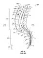
- FIG. 10shows the lumbar region 122 , the sacral region 124 and the coccyx 126 of the spine 120 and that the vertebrae 100 are stacked one upon another.
- the top portion 100 a and bottom portion 100 b of each vertebrae 100is slightly concave.
- the opposing concave vertebral surfacesform the intervertebral space 121 in which an intervertebral disk (not shown) resides.
- Each of the intervertebral diskshas a soft core referred to as a nucleus pulposus or nucleus (not shown).
- each vertebrae 100includes a body 106 in the innermost portion, a spinal canal 108 and a spinous process 102 at the posterior-most end of the vertebra 100 .
- the vertebrae 100are substantially similar in composition, but vary in size from the larger lumbar to the smallest coccyx vertebrae 126 .
- Each vertebrae 100further includes two transverse processes 104 located on either side and a protective plate-like structure referred to as a lamina 110 . Nerves from the spinal cord 128 pass through the spinal canal 108 and foramina 111 to reach their respective destinations within the body.
- the natural aging processcan cause a deterioration of the intervertebral disks, and therefore, their intrinsic support strength and stability is diminished. Sudden movements may cause a disk to rupture or herniate. A herniation of the disk is primarily a problem when the nucleus pulposus protrudes or ruptures into the spinal canal 108 placing pressure on nerves which in turn causes spasms, tingling, numbness, and/or pain in one or more parts of the body, depending on the nerves involved.
- Surgical optionsinclude chemonucleolysis, laminectomy, diskectomy, microdiskectomy, and spinal fusion.
- Chemonucleolysisis the injection of an enzyme, such as chymopapain, into the disk to dissolve the protruding nucleus pulposus.
- the enzymeis a protein-digesting enzyme and is used to dissolve the disk material. Since the enzyme is essentially a tissue-dissolving agent, it is indiscriminate in the protein-based matter it dissolves. Should the enzyme be injected into the wrong place, or if there is a breach in the disk capsule that would allow the solution to enter the spinal canal or to contact nerve tissue or the like, the resultant damage to nerve tissue could not be reversed. Even worse, about half of the patients who receive chemonucleolysis treatments experience increased back pain and muscle spasms immediately after the injection and more than half have incapacitating back pain for durations up to three months after such treatments.
- a laminectomyis performed to decompress the spinal canal 108 by open surgical techniques under general anesthesia.
- the lamina 110(the bone that curves around and covers the spinal canal 108 as shown in FIG. 9 ), and any disk tissue causing pressure on a nerve or the spinal canal 108 , are partially removed.
- This techniqueis highly invasive and traumatic to the body, and therefore requires an extended recovery time of about five weeks and a hospital stay of a few days.
- the vertebrae 100may shift due to the lack of support in the structure.
- simply removing the disk and parts of the vertebral boneis a short-term, pain-relieving corrective action but not a long-term solution.
- Diskectomyis a form of spinal surgery wherein part or all of an intervertebral disk is excised typically through open surgical techniques. Recently, less invasive techniques referred to as percutaneous diskectomy or microdiskectomy have been developed to reduce the surgical trauma to the patient. In microdiskectomy, a much smaller incision is made than in normal open surgeries. A small retractor, working channel or tube is inserted through the posterior muscles (not shown) to allow access to the damaged or herniated disk.
- the curetteis a spoon-shaped instrument with a sharp edge that is used mainly to scrape the nucleus pulposus matter (not shown) from the end plates of the vertebral bones.
- the bladeSince the blade is unprotected, there is potential for damage to the surrounding nerves and ligaments during insertion and during use. Further, due to the varying concavity of the vertebral space (or the concavity of the top and bottom portions 100 a,b of the vertebral bones) it is often a time consuming procedure for the surgeon to repeatedly scrape at varying angles using the curette.
- Another instrument that is often usedis the reamer (not shown) which is intended to remove the nucleus pulposus matter more quickly than a curette.
- the reameris usually a cylindrically-shaped, drill-bit-like device with a flat tip and a plurality of sharp edges along its outer sides.
- the reameris continuously turned inside the vertebral disk space 121 to scrape the nucleus pulposus matter from the vertebral bones; however, reamers often cause damage to adjacent vertebrae and may cause damage to nerves, blood vessels and/or ligaments while being inserted into the intervertebral space.
- a damaged diskmay be completely removed.
- Parts of a bone from another part of the body, such as the pelvis,are harvested, and the bone parts or grafts are subsequently placed between the adjacent vertebrae 100 so that the adjacent vertebrae 100 grow together in a solid mass.
- the posterior lamina 110 and the centers of the vertebral bodies 106may both be cut. The surgery often involves consequential damage to the associated posterior ligaments, muscles and joints in addition to the removal of part or all of the lamina 110 .
- the recovery time for a normal spinal fusion surgeryis significant due not only to the fact that normal movement cannot be allowed until detectable bone growth has occurred between the bone grafts and the adjacent vertebrae 100 , but the associated ligaments, muscles and the location where the bone grafts were harvested must also recover. Oftentimes portions of the spine 120 must be immobilized during the recovery period causing added discomfort and inconvenience to the patient.
- a surgical instrument for performing partial diskectomiesthat is minimally invasive, easy to use, safe to insert into the body during surgery, provides rapid removal of the nucleus pulposus matter, and which does not cause undesired damage to adjacent vertebrae.
- a micro surgical techniquethat allows for fast patient recovery times and that can be used on an outpatient basis.
- the present inventioncomprises a diskectomy instrument.
- the diskectomy instrumentincludes an elongate body, at least one blade and a drive stem.
- the elongate bodyhas a distal end and a proximal end.
- the elongate bodyhas at least one blade opening proximate the distal end.
- the at least one bladeis removably and movably mounted at least partially within the elongate body proximate the at least one blade opening.
- the at least one bladehas a distal end, a proximal end, at least one sharp edge extending at least partially between the distal end and the proximal end, a ramped portion and a stem mating portion.
- the drive stemis movably mounted within the elongate body.
- the drive stemhas a distal end, a proximal end and a blade mating portion.
- the drive stemis configured to slidably engage the at least one blade when the drive stem is moved distally thereby extending the at least one blade radially outward though the at least one blade opening.
- the blade mating portionis configured to cooperatively engage the stem mating portion of the blade when the drive stem is moved proximally thereby retracting the at least one blade.
- the present inventionfurther comprises a diskectomy instrument including an elongate body, a plurality of blades and a drive stem.
- the elongate bodyhas a distal end and a proximal end.
- the elongate bodyhas a plurality of blade openings proximate the distal end.
- the plurality of bladesare removably and movably mounted at least partially within the elongate body. Each blade is disposed proximate to a respective one of the plurality of blade openings.
- the plurality of bladeseach have a distal end, a proximal end, at least one sharp edge extending at least partially between the distal end and the proximal end, a ramped portion and a stem mating portion.
- the drive stemis movably mounted within the elongate body and has a distal end, a proximal end and a blade mating portion.
- the drive stemis configured to slidably engage each of the plurality of blades when the drive stem is moved distally thereby extending the plurality of blades radially outward though the respective plurality of blade openings.
- the blade mating portionis configured to cooperatively engage the stem mating portion of each of the plurality of blades when the drive stem is moved proximally thereby retracting the plurality of blades.
- the present inventionfurther comprises a diskectomy blade having a distal end and a proximal end for use in a diskectomy instrument.
- the diskectomy instrumentincludes a drive stem having a blade mating portion.
- the bladeincludes at least one sharp edge, a ramped portion and a stem mating portion.
- the at least one sharp edgeextends at least partially between the distal end and the proximal end.
- the ramped portionis configured to slidably engage one of the drive stem and the body of the diskectomy instrument.
- the stem mating portionis configured to couple with the blade mating portion of the diskectomy instrument.
- the present inventionfurther comprises a method of using a diskectomy instrument.
- the diskectomy instrumentincludes an elongate body having a blade opening, a blade having a sharp edge, a ramped portion and a stem mating portion.
- the diskectomy instrumentalso includes a drive stem having a blade mating portion.
- the drive stemis configured to slidably engage the at least one blade when the drive stem is moved distally thereby extending the blade radially outward though the blade opening.
- the blade mating portion of the drive stemis configured to cooperatively engage the stem mating portion of the blade when the drive stem is moved proximally thereby retracting the blade.
- the methodincludes the step of moving the drive stem proximally causing the blade mating portion to engage the stem mating portion of the blade thereby retracting the blade at least partially into the elongate body.
- the methodalso includes the steps of inserting a distal end of the diskectomy instrument into a small gap between a first vertebra and a second vertebra of a spine and moving the drive stem distally causing the blade mating portion to engage the blade which in turn moves the blade distally and radially outward.
- the methodfurther includes the steps of rotating the blade in a cutting direction defined by the orientation of the sharp edge and moving the drive stem proximally causing the blade mating portion to engage the stem mating portion of the blade thereby retracting the blade at least partially into the elongate body.
- the methodfurther includes the step of withdrawing the distal end of the diskectomy instrument from the small gap.
- the present inventionfurther comprises a method of using a diskectomy instrument and a working tube in outpatient surgery.
- the diskectomy instrumentincludes an elongate body having a blade opening, a blade having a sharp edge and a partially convex shape, a ramped portion and a stem mating portion.
- the diskectomy instrumentalso includes a drive stem having a blade mating portion.
- the drive stemis configured to slidably engage the at least one blade when the drive stem is moved distally thereby extending the blade radially outward though the blade opening.
- the blade mating portionis configured to cooperatively engage the stem mating portion of the blade when the drive stem is moved proximally thereby retracting the blade.
- the methodincludes the step of moving the drive stem proximally causing the blade mating portion to engage the stem mating portion of the blade thereby retracting the blade at least partially into the elongate body.
- the methodalso includes the steps of inserting a distal end of the working tube proximate a small gap between a first vertebra and a second vertebra of a spine accessible through an incision between about 10 mm and about 100 mm in span and inserting a distal end of the diskectomy instrument into the working tube in order to access the intervertebral space between the first and second vertebrae.
- the methodincludes the steps of moving the drive stem distally causing the drive stem to engage the blade which in turn moves the blade distally and radially outward and rotating the blade in a cutting direction defined by the orientation of the sharp edge so that the convexly-shaped blade finds the most concave portions of the first and second vertebrae.
- the methodincludes the steps of moving the drive stem proximally causing the blade mating portion to engage the stem mating portion of the blade thereby retracting the blade at least partially into the elongate body and withdrawing the distal end of the diskectomy instiument from the working tube.
- FIG. 1is a side elevational view of a diskectomy instrument in accordance with the preferred embodiment of the present invention
- FIG. 2is a greatly enlarged side sectional view of a portion of the diskectomy instrument of FIG. 1 in a retracted position;
- FIG. 3is a greatly enlarged side sectional view of a portion of diskectomy instrument of FIG. 1 in an extended position;
- FIG. 4is a side elevational view of a blade used in a diskectomy instrument in accordance with the present invention.
- FIG. 5is a perspective view of the blade of FIG. 4;
- FIG. 6is a greatly enlarged sectional view of a portion of the diskectomy instrument taken along line 6 — 6 , FIG. 1;
- FIG. 7is a greatly enlarged sectional view of a portion of the diskectomy instrument taken along line 7 — 7 , FIG. 1;
- FIG. 8is a front elevational view of the blade of FIG. 4;
- FIG. 9is a top sectional view of a human vertebrae as is known in the art.
- FIG. 10is a side sectional view of the lumbar and sacral regions of a human spine as in known in the art
- FIG. 11is a side elevational view of a first actuator mechanism for a diskectomy instrument in accordance with the present invention.
- FIG. 12is a side elevational view of a second actuator mechanism for a diskectomy instrument in accordance with the present invention.
- FIGS. 13A-13Eare greatly enlarged sectional views of several preferred embodiments of diskectomy blades in accordance with the present invention.
- FIG. 1a diskectomy instrument 12 in accordance with a preferred embodiment of the present invention.
- the diskectomy instrument 12includes an elongate body 18 , a probe assembly 20 , an actuator mechanism 13 , a blade positioning knob 14 and a handle or blade rotation knob 16 .
- the diskectomy instrument 12has a distal end 12 a and a proximal end 12 b .
- the probe assembly 20can be integral or part of the elongate body 18 .
- the portions of the diskectomy instrument 12 intended to contact internal human body matterare formed of a biologically compatible material selected such as stainless steel, titanium, nickel plated metal, any biocompatible metal or alloy, a biocompatible ceramic, a biocompatible polymeric material and the like.
- the elongate body 18is between about 5 mm and 30 mm in diameter making it ideally suited for use in outpatient minimally invasive surgery.
- the diskectomy instrument 12is used in combination with a working tube 50 of only slightly greater diameter which provides a portal to the small gap between two adjacent vertebrae 100 as will be described in greater detail hereinafter.
- the working tube 50preferably has an elongate housing 52 having a distal end 52 a , a proximal end 52 b and an interior lumen 53 traversing through the elongate housing 52 .
- the working tubeis configured to be inserted through an incision between about 5 mm and about 100 mm in span, but is more preferably configured to be inserted through an incision of less than about 25 mm in span.
- the working tube 50 and the diskectomy tool 12can be configured to be inserted through incisions or openings having other dimensions and can be used in conventional open surgery without departing from the present invention.
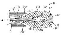
- FIG. 2shows a side cutaway of the distal end 12 a of the diskectomy instrument 12 providing a much more detailed view of the probe assembly 20 .
- the probe assembly 20includes a probe body 22 , a drive stem 21 , an inner sheath 24 , a biasing cone 25 and at least one blade 26 .
- the probe body 22includes a blade opening 27 for each blade 26 .
- the blade opening 27has a distal end 27 a and a proximal end 27 b .
- each blade opening 27is generally rectangularly-shaped. But, the blade openings 27 may be other shapes.
- the blade openings 27are selected to be only slightly wider than the blades 26 in order to provide lateral support to the blades 26 when the blades 26 are radially extended. The close tolerance between the blade openings 27 and the blades 26 also assists in preventing foreign materials from being trapped in between the blades 26 and the blade openings 27 when the blades 26 are being retracted.
- the drive stem 21has a distal end 21 a and a proximal end 21 b (FIG. 1 ).
- a stem end-cap 23is positioned on the distal end 21 a of the drive stem 21 and includes a proximal end 23 b and a distal end 23 a , the distal end preferably being configured as a dome-shaped or rounded conically-shaped surface 23 c as discussed more fully below.
- the proximal end 23 b and the dome-shaped surface 23 c of the stem end-cap 23form a blade mating portion 23 b , 23 c of the drive stem 21 .
- the drive stem 21is slidably mounted within the probe 20 and is configured to slidably engage the blades 26 when the drive stem 21 is moved distally thereby moving the blades 26 distally and extending the blades 26 radially outward through the blade openings 27 .
- the drive stem 21or more particularly, the blade mating portion(s) 23 b , 23 c of the drive stem 21 is configured to cooperatively engage a stem mating portion 29 of the blades 26 when the drive stem 21 is moved proximally thereby moving the blades 26 proximally and retracting the blades 26 radially inward.
- other more complicated mechanical arrangementsmay be coupled between the drive stem 21 and the blades 26 without departing from the present invention.
- each of the blades 26is preferably identical and includes a distal end 26 a and proximal end 26 b . It is contemplated, however, that the blades 26 need not be identical to one another and that the blades 26 may also be matched in opposing pairs or may each be unique with respect to the others.
- the blades 26are preferably formed of a hard, bio-compatible metal such as stainless steel, titanium, nickel, metal alloy, or the like. But, the blades 26 can be formed of other materials. It should be noted that the blades 26 are rigid. Each blade 26 preferably has an asymmetrical shape as best shown in FIGS. 4-5; however, the blades 26 may be other shapes without departing from the broad scope of the present invention. Preferably, the blades are generally convexly-shaped proximate the at least one sharp edge 32 thereby allowing the blades 26 to naturally find the most concave portions 100 a or 100 b of a particular vertebra 100 .
- the blades 26may be reusable after suitable sterilization as is known in the art, but preferably, the blades 26 are disposable. Accordingly, the blades 26 are preferably removably and movably mounted in the probe 20 within the elongate body 18 of the diskectomy tool 12 . In one embodiment, the distal end 12 a of the diskectomy instrument 12 is at least partially open or the end of the probe 20 is removable to allow the blades 26 to be removed from the distal end 12 a of the diskectomy tool 12 . Preferably, however, the blades 26 are removed proximally through the elongate body 18 allowing the end of the probe 20 to be generally closed and bluntly rounded.
- each bladehas an inner face 30 and an outer surface 32 having at least one sharpened edge 38 extending at least partially between the distal end 26 a and the proximal end 26 b of the blade 26 .
- the stem mating portion 29 of the blades 26are configured to cooperatively engage the blade mating portion 23 b , 23 c of the drive stem 21 .
- each blade 26includes a notch 34 having a retracting ledge 35 defining the stem mating portion 29
- each blade 26also includes an extending ramp 36 .
- each blade 26has two or more ramps 36 to firmly guide the blade 26 radially outward.
- the retracting ledge 35accommodates a portion of the proximal end 23 b of the stem end-cap 23 which defines the blade mating portion 23 b , 23 c of the drive stem 21 .
- the extending ramp 36cooperates with the dome-shaped surface 23 c of the end-cap 23 .
- the end-cap 23is attached to or integrally formed with the drive stem 21 at the most distal end 21 a of the drive stem 21 .
- the end-cap 23is preferably hemispherically-shaped wherein the proximal end 23 b is generally flat and the distal end 23 a includes the spherical portion defining the dome-shaped surface 23 c .
- the stem end-cap 23 of the preferred embodimentis hemispherically shaped
- the stem end-cap 23may have other shapes such as an egg shape, a bullet shape, a conical shape, a pyramidal shape or the like without departing from the broad inventive concept herein.
- the stem end-cap 23may also have other cooperative shapes and/or structures as well including for example protuberances and detents. For example, if the blade mating portion 23 b , 23 c of the drive stem 21 is a protuberance then the stem mating portion 29 of the blade 26 is a cooperatively shaped indentation or the like.
- the stem mating portion 29 of the blade 26is a cooperatively shaped protuberance.
- the blade mating portion 23 b , 23 c of the drive stem 21 and the stem mating portion 29 of the blade 26may be other cooperative shapes suitable for engaging one another without departing from the present invention.
- each blade 26includes a bidirectional sharp cutting edge 38 spanning both sides of the blade 26 .
- the blades 26may also include a plurality of sharp cutting edges 38 emanating from the same side of the at least one sharpened edge 38 .
- the blades 26include only one sharpened edge 28 facing one direction.
- the sharpened edges 38tend to cut but when the blades 26 are rotated in the opposite direction the blades 26 tend not to cut.
- the blades 26could be designed to cut in either direction or both directions without departing from the present invention.
- the distal end 26 a of the blade 26is preferably blunted or dull to cooperatively engage the biasing cone 25 when the stem 21 pushes the blades 26 with force in the distal direction thereby causing the blades 26 to move distally and radially outward.
- the elongate body 18further comprises a fixed abutment (not shown) configured to engage the ramp 36 when the drive stem 21 is moved distally thereby assisting in extending the blades 26 radially outward.
- the probe assembly 20is mechanically coupled by known methods to either the elongate body 18 or the interior portion of the blade rotation knob 16 such that rotation of the blade rotation knob 16 in turn rotates the probe assembly 20 thereby rotating the blades 26 .
- the blade rotation knob 16is preferably coupled to the blades 26 and rotating the blade rotation knob 26 causes the blades 26 to rotate in a cutting direction.
- the proximal end 26 b of the blades 26is sloped such that the proximal end of surface 32 cooperatively engages an inner wedged surface 24 a of the inner sheath 24 .
- Proximal movement of the blades 26causes a sloped portion of each outer surface 32 to engage the inner wedged surface 24 a of the inner sheath 24 , thereby causing the blades 26 to also retract inwardly as well as proximally.
- the proximal end 27 a of the blade openings 27also engages the sloped portion of the outer surface 32 , thereby assisting the inner wedged surface 24 a of the inner sheath 24 in imparting inward movement on the blades 26 .
- Such a configurationprovides the surgeon or other user with a mechanical advantage when retracting the blades 26 so that foreign matter can be easily jettisoned from the blades 26 as they are retracted through the blade openings 27 .
- the blade positioning knob 14is moved proximally which pulls drive stem 21 in the direction of arrow A (FIG. 2) causing the proximal end 23 b of the stem cap 23 to engage the retracting ledge 35 , thereby biasing the blades 26 inwardly and proximally toward the inner sheath 24 .
- the distal end 12 a of the diskectomy instrument 12is then inserted through the working tube 50 as is known in the art and into a small gap between a first vertebra and a second adjacent vertebra. Since the distal end 12 a of the diskectomy instrument 12 is somewhat blunted, there is minimal risk of damaging ligaments, muscles, nerves, or the like during the insertion process.
- the diskectomy instrument 12is inserted from the posterior direction 101 a at a location off-center such as in the direction of Arrow C (FIG. 9 ). While the diskectomy instrument 12 is described in the context of microdiskectomy surgery, uses of the instrument 12 are not limited to such surgeries. It is also possible to use the diskectomy instrument 12 in conventional open surgeries such as laminectomies, diskectomies, spinal fusions, and the like.
- the surgeoncan press or rotate the blade positioning knob 14 driving the drive stem 21 distally.
- the drive stem 21moves distally in the direction of arrow B (FIG. 3) causing the dome-shaped surface 23 c of the stem cap 23 to cooperatively engage the extending ramps 36 of the blades 26 and forcing the distal end 26 a of the blades 26 to engage the biasing cone 25 thereby causing the blades 26 to move outwardly such that the sharpened edge 38 extends through the blade openings 27 and beyond the outside of the probe assembly 20 .
- the surgeonrotates the blade rotation knob 16 in either a clockwise or counter-clockwise direction, depending on the direction of the sharpened edge 38 of the blades 26 , causing the probe assembly 20 and the associated blades 26 to rotate therewith and providing a rapid debridement of the nucleus pulposus of the intervertebral disk.
- the curved and outwardly-biased blades 26accommodate the natural concavity of the adjacent vertebrae 100 which significantly reduces the amount of time required to enucleate the disk space 121 .
- the blades 26will allow abrasion of the top concave portion 100 a of a vertebra and the opposing lower concave portion 100 b of the adjacent vertebra to encourage bone ingrowth into devices such as artificial disks, bone grafts, non-bone fusion devices, and the like. If desired, the blades 26 can be used for the partial removal of the end plate (not shown clearly). Due to the size and smooth contour shape of the blades 26 , the outer layers of annular ligament and the majority of circumferential edges of the vertebral bodies 106 are able to be preserved which is beneficial to the support of the vertebrae 100 when an interbody device such as an artificial disk or a fusion apparatus is installed after the diskectomy procedure is completed. Such a diskectomy instrument 12 is ideally suited for only removing the nucleus between two adjacent vertebrae 100 while only minimally removing parts of the surrounding bone and annulus.
- the blade positioning knob 14is moved proximally or rotated in a direction which causes the drive stem 21 to move proximally (i.e., in the direction of arrow A in FIG. 2) again causing the proximal end 23 b of the stem cap 23 to engage the retracting ledge 35 of the blades 26 thereby returning the blades 26 to the retracted position.
- the shape of the blade openings 27 , the blades 26 , the inner sheath 24 , and the probe body 22naturally deters foreign matter such as fragments of the nucleus pulposus, bone matter and the like from being trapped between the blades 26 and other parts of the diskectomy instrument 12 .
- the diskectomy instrument 12can then be moved proximally by pulling on the blade rotation knob 16 removing the distal end 12 a of the diskectomy instrument 12 from the small gap and subsequently the entire diskectomy instrument 12 from the working tube 50 and/or from the body so that the enucleated disk matter can be removed under fluoroscopy or endoscopy by conventional devices such as forceps, graspers, suction devices, and the like.
- the blade positioning knob 14While in the presently preferred embodiment there is shown a simple knob (the blade positioning knob 14 ) connected to the drive stem 21 which is used to radially extend and retract the blades 26 , other actuation devices may be utilized without departing from the present invention.
- the actuator mechanism 13 or simply the actuator 13is coupled to the proximal end 21 b of the drive stem 21 to effectuate proximal and distal movement of the drive stem 21 linearly within the elongate body 18 .
- the actuator 13is the positioning knob 14 that is configured to rotate in a first direction to cause the drive stem 21 to move distally and to rotate in a second direction to cause the drive stem to move proximally.
- the blade positioning knob 14is separately coupled to the actuator 13 .
- the blade positioning knob 14includes incremental indication marks 15 which at least generally correspond to the radial position of the blades 26 relative to the elongate body 18 .
- the incremental indication marks 15would also provide the surgeon with a gauging or measuring feature of the diskectomy tool 12 allowing the surgeon to measure the intervertebral space 121 prior to inserting any device. The surgeon simply rotates the positioning knob 14 until the blades 26 are firmly touching vertebrae 100 and then can read the distance using the incremental indication marks 15 .
- FIG. 11shows another embodiment of an actuator 13 ′.
- the proximal end 21 b of the drive stem 21is externally toothed (teeth 21 d ) and the actuator 13 ′ includes a drive gear 40 .
- the actuator 13 ′is rotatably mounted to the proximal end 18 b of the elongate body 18 in such a manner that the teeth 21 d of the drive stem 21 are in mesh engagement with the drive gear 40 of the actuator 13 ′.
- Rotation of the drive gear 40 in a first directioncauses the drive stem 21 to move distally and rotation of the drive gear 40 in a second direction causes the drive stem 21 to move proximally.
- One possible rotatable blade positioning knob 14 ′is depicted as being disposed proximally to a blade rotation knob 16 ′ and has teeth 14 a ′ engaged with the drive gear 40 .
- FIG. 12shows another embodiment of an actuator 13 ′′ where the proximal end 21 b of the drive stem 21 is externally threaded (threads 21 e ) and the actuator 13 ′′ is internally threaded (threads 13 a ′′).
- the actuator 13 ′′is rotatably mounted to the proximal end 18 b of the elongate body 18 in such a manner that the external threads 21 e of the drive stem 21 are in threaded engagement with the internal threads 13 a ′′ of the actuator 13 ′′.
- Rotation of the actuator 13 in a first directioncauses the drive stem 21 to move distally and rotation of the actuator 13 in a second direction causes the drive stem 21 to move proximally by translation of the internal and external threads 13 a ′′, 21 e ′′, respectively.
- the actuator 13 ′′preferably includes a plurality of suitable reduction gears 42 - 43 as is known in the art to enable a user to precisely position the blades 26 .
- One possible rotatable blade positioning knob 14 ′′is depicted as being disposed proximally to a blade rotation knob 16 ′′ and has teeth 14 a ′′ engaged with the drive gear 41 .
- the drive stem 21is actuated using scissors-like hand grips which may or may not have mechanical stops or limits for adjusting how far the drive stem is extended distally. It should be recognized that the particular method of actuating the drive stem 21 is not critical to the present invention.
- the blade rotation knob 16is depicted as having a knurled or textured surface, the blade rotation knob 16 may also be more complex without departing from the broad scope of the present invention.
- the handlemay be a two-piece assembly wherein a ratchet mechanism 17 is located between, for example, an inner and outer piece, allowing the surgeon to use partial turns of the blade rotation knob 16 effectuate rotation of the at least one blade in the cutting direction (i.e., to rotate the blades 26 in one direction).
- a more complex mechanical assemblymay include a side handle gearedly connected by directional translation gears, such as worm gears, helical gears, bevel gears and the like, to a rotational drive gear (not shown) connected to the probe assembly 20 allowing the surgeon to crank the side handle in a fashion similar to an egg beater thereby rotating the probe assembly 20 including the blades 26 in the cutting direction.
- directional translation gearssuch as worm gears, helical gears, bevel gears and the like
- the relative location of the blade rotation knob 16 and the blade positioning knob 14is not critical to the present invention.
- the blade positioning knob 14may alternatively be disposed on the proximal portion of the elongate body 18 and the blade rotation knob 16 may be disposed proximal to the blade positioning knob 14 .
- FIGS. 13A-13Eare greatly enlarged sectional views of several preferred embodiments of diskectomy blades in accordance with the present invention.
- FIG. 13Ashows a diskectomy blade 126 having a single sharpened edge 138 and a substantially box-like backing 137 for added structural support to the sharpened edge 138 of the diskectomy blade 126 .
- the diskectomy blade 126is a unidirectional type diskectomy blade which cuts in only one direction.
- FIG. 13Bshows another diskectomy blade 226 having a single sharpened edge 238 , however the back 238 a of the sharpened edge 238 is generally rounded or sloped.
- the diskectomy blade 226is also a unidirectional type diskectomy blade.
- FIG. 13Ashows a diskectomy blade 126 having a single sharpened edge 138 and a substantially box-like backing 137 for added structural support to the sharpened edge 138 of the diskectomy blade 126 .
- the diskectomy blade 126is a unidirectional type diskectomy blade which cuts in only one direction.
- FIG. 13Cshows another diskectomy blade 326 having a single sharpened edge 338 and a generally sloped flat back 338 a of the sharpened edge 138 , 238 , 338 .
- the diskectomy blade 326is also a unidirectional type diskectomy blade. Obviously, the sharpened edge 138 , 238 , 338 of all of the unidirectional type diskectomy blades 126 , 226 , 326 could face in the opposite direction of those shown without departing from the present invention.
- FIG. 13Dshows a diskectomy blade 426 that has a pair of oppositely facing sharpened edges 438 .
- the diskectomy blade 426is a bidirectional type diskectomy blade which cuts when rotating in either direction (clockwise or counterclockwise rotation).
- FIG. 13Eshows a serrated diskectomy blade 526 having multiple sharpened edges 538 alternately disposed along its length, and therefore, the diskectomy blade 526 is another bidirectional type diskectomy blade.
Landscapes
- Health & Medical Sciences (AREA)
- Surgery (AREA)
- Life Sciences & Earth Sciences (AREA)
- Biomedical Technology (AREA)
- Medical Informatics (AREA)
- Orthopedic Medicine & Surgery (AREA)
- Veterinary Medicine (AREA)
- Engineering & Computer Science (AREA)
- Public Health (AREA)
- Heart & Thoracic Surgery (AREA)
- Nuclear Medicine, Radiotherapy & Molecular Imaging (AREA)
- Molecular Biology (AREA)
- Animal Behavior & Ethology (AREA)
- General Health & Medical Sciences (AREA)
- Dentistry (AREA)
- Oral & Maxillofacial Surgery (AREA)
- Surgical Instruments (AREA)
- Micro-Organisms Or Cultivation Processes Thereof (AREA)
- Toys (AREA)
Abstract
Description
Claims (31)
Priority Applications (3)
| Application Number | Priority Date | Filing Date | Title |
|---|---|---|---|
| US10/345,525US6726690B2 (en) | 2002-01-17 | 2003-01-16 | Diskectomy instrument and method |
| US10/731,288US6939351B2 (en) | 2002-01-17 | 2003-12-09 | Diskectomy instrument and method |
| US11/135,219US7699849B2 (en) | 2002-01-17 | 2005-05-23 | Diskectomy instrument with disposable blade head |
Applications Claiming Priority (3)
| Application Number | Priority Date | Filing Date | Title |
|---|---|---|---|
| US34974202P | 2002-01-17 | 2002-01-17 | |
| US36970102P | 2002-04-02 | 2002-04-02 | |
| US10/345,525US6726690B2 (en) | 2002-01-17 | 2003-01-16 | Diskectomy instrument and method |
Related Child Applications (1)
| Application Number | Title | Priority Date | Filing Date |
|---|---|---|---|
| US10/731,288ContinuationUS6939351B2 (en) | 2002-01-17 | 2003-12-09 | Diskectomy instrument and method |
Publications (2)
| Publication Number | Publication Date |
|---|---|
| US20030135218A1 US20030135218A1 (en) | 2003-07-17 |
| US6726690B2true US6726690B2 (en) | 2004-04-27 |
Family
ID=27737405
Family Applications (2)
| Application Number | Title | Priority Date | Filing Date |
|---|---|---|---|
| US10/345,525Expired - LifetimeUS6726690B2 (en) | 2002-01-17 | 2003-01-16 | Diskectomy instrument and method |
| US10/731,288Expired - LifetimeUS6939351B2 (en) | 2002-01-17 | 2003-12-09 | Diskectomy instrument and method |
Family Applications After (1)
| Application Number | Title | Priority Date | Filing Date |
|---|---|---|---|
| US10/731,288Expired - LifetimeUS6939351B2 (en) | 2002-01-17 | 2003-12-09 | Diskectomy instrument and method |
Country Status (7)
| Country | Link |
|---|---|
| US (2) | US6726690B2 (en) |
| EP (1) | EP1471840B1 (en) |
| JP (1) | JP2005538748A (en) |
| AT (1) | ATE480194T1 (en) |
| AU (1) | AU2003203044A1 (en) |
| DE (1) | DE60334071D1 (en) |
| WO (1) | WO2003065909A1 (en) |
Cited By (48)
| Publication number | Priority date | Publication date | Assignee | Title |
|---|---|---|---|---|
| US20030181915A1 (en)* | 2002-03-19 | 2003-09-25 | Hassan Serhan | Novel vertebral endplate milling device |
| US20040092988A1 (en)* | 2002-11-08 | 2004-05-13 | Shaolian Samuel M. | Transpedicular intervertebral disk access methods and devices |
| US20040215197A1 (en)* | 2003-04-24 | 2004-10-28 | Smith Maurice M. | Minimally invasive instruments and methods for preparing vertebral endplates |
| US20050261692A1 (en)* | 2004-05-21 | 2005-11-24 | Scimed Life Systems, Inc. | Articulating tissue removal probe and methods of using the same |
| US20050277971A1 (en)* | 2004-06-15 | 2005-12-15 | Melkent Anthony J | Minimally invasive instruments and methods for preparing vertebral endplates |
| US20060241566A1 (en)* | 2005-04-11 | 2006-10-26 | Orthox, Llc | Nucleus Extraction from Spine Intervertebral Disc |
| US20060276816A1 (en)* | 2005-06-06 | 2006-12-07 | Concept Matrix, Llc | Multi-Blade Curette Tool |
| US20070055259A1 (en)* | 2005-08-17 | 2007-03-08 | Norton Britt K | Apparatus and methods for removal of intervertebral disc tissues |
| US20070162062A1 (en)* | 2005-12-08 | 2007-07-12 | Norton Britt K | Reciprocating apparatus and methods for removal of intervertebral disc tissues |
| US20070265633A1 (en)* | 2006-05-11 | 2007-11-15 | Moon Jon K | Implement and method to extract nucleus from spine intervertebral disc |
| US20070270863A1 (en)* | 2006-04-20 | 2007-11-22 | Sdgi Holdings, Inc. | Devices and methods for contouring an intervertebral space between vertebral members |
| US20080177294A1 (en)* | 2006-10-16 | 2008-07-24 | Depuy Spine, Inc. | Expandable intervertebral tool system and method |
| US20090306689A1 (en)* | 2008-06-05 | 2009-12-10 | Cardiovascular Systems, Inc. | Bidirectional expandable head for rotational atherectomy device |
| US20110166575A1 (en)* | 2010-01-04 | 2011-07-07 | Zyga Technology, Inc. | Sacroiliac fusion system |
| US8900279B2 (en) | 2011-06-09 | 2014-12-02 | Zyga Technology, Inc. | Bone screw |
| US8900251B2 (en) | 2010-05-28 | 2014-12-02 | Zyga Technology, Inc | Radial deployment surgical tool |
| US9101371B2 (en) | 2010-11-03 | 2015-08-11 | Zyga Technology, Inc. | Method of repairing sacroiliac fusion |
| US9192451B2 (en)* | 2012-07-20 | 2015-11-24 | Schubert L. Sapian | Oscillating blade for cutting periodontal ligaments and luxating tooth roots |
| US9314279B2 (en) | 2004-10-20 | 2016-04-19 | The Board Of Trustees Of The Leland Stanford Junior University | Systems and methods for posterior dynamic stabilization of the spine |
| US9517076B2 (en) | 2014-03-11 | 2016-12-13 | Lenkbar, Llc | Reaming instrument with adjustable profile |
| US9532812B2 (en) | 2004-10-20 | 2017-01-03 | Vertiflex, Inc. | Interspinous spacer |
| US9572603B2 (en) | 2004-10-20 | 2017-02-21 | Vertiflex, Inc. | Interspinous spacer |
| US9603607B2 (en) | 2014-03-11 | 2017-03-28 | Lenkbar, Llc | Reaming instrument with adjustable profile |
| US9675303B2 (en) | 2013-03-15 | 2017-06-13 | Vertiflex, Inc. | Visualization systems, instruments and methods of using the same in spinal decompression procedures |
| US9861398B2 (en) | 2004-10-20 | 2018-01-09 | Vertiflex, Inc. | Interspinous spacer |
| US9956011B2 (en) | 2004-10-20 | 2018-05-01 | Vertiflex, Inc. | Interspinous spacer |
| US10039576B2 (en) | 2004-10-20 | 2018-08-07 | The Board Of Trustees Of The Leland Stanford Junior University | Systems and methods for posterior dynamic stabilization of the spine |
| US10045803B2 (en) | 2014-07-03 | 2018-08-14 | Mayo Foundation For Medical Education And Research | Sacroiliac joint fusion screw and method |
| US10058358B2 (en) | 2004-10-20 | 2018-08-28 | The Board Of Trustees Of The Leland Stanford Junior University | Systems and methods for posterior dynamic stabilization of the spine |
| US10080587B2 (en) | 2004-10-20 | 2018-09-25 | Vertiflex, Inc. | Methods for treating a patient's spine |
| US10258792B2 (en)* | 2005-07-22 | 2019-04-16 | The Spectranetics Corporation | Endocardial lead cutting apparatus |
| US10271859B2 (en) | 2014-01-09 | 2019-04-30 | Rti Surgical, Inc. | Undercutting system for use in conjunction with sacroiliac fusion |
| US10278744B2 (en) | 2004-10-20 | 2019-05-07 | The Board Of Trustees Of The Leland Stanford Junior University | Systems and methods for posterior dynamic stabilization of the spine |
| US10292738B2 (en) | 2004-10-20 | 2019-05-21 | The Board Of Trustees Of The Leland Stanford Junior University | Systems and methods for stabilizing the motion or adjusting the position of the spine |
| US10413332B2 (en) | 2016-04-25 | 2019-09-17 | Imds Llc | Joint fusion implant and methods |
| US10441295B2 (en) | 2013-10-15 | 2019-10-15 | Stryker Corporation | Device for creating a void space in a living tissue, the device including a handle with a control knob that can be set regardless of the orientation of the handle |
| US10524772B2 (en) | 2014-05-07 | 2020-01-07 | Vertiflex, Inc. | Spinal nerve decompression systems, dilation systems, and methods of using the same |
| US10588663B2 (en) | 2006-10-18 | 2020-03-17 | Vertiflex, Inc. | Dilator |
| US10603177B2 (en) | 2016-04-25 | 2020-03-31 | Imds Llc | Joint fusion instrumentation and methods |
| US10610267B2 (en) | 2004-10-20 | 2020-04-07 | Vertiflex, Inc. | Spacer insertion instrument |
| US10709481B2 (en) | 2004-10-20 | 2020-07-14 | The Board Of Trustees Of The Leland Stanford Junior University | Systems and methods for posterior dynamic stabilization of the spine |
| US11160577B2 (en) | 2017-08-01 | 2021-11-02 | Advance Research System, Llc | Lateral disc cutter |
| US11229461B2 (en) | 2006-10-18 | 2022-01-25 | Vertiflex, Inc. | Interspinous spacer |
| US11633205B1 (en) | 2017-08-01 | 2023-04-25 | Advance Research System, Llc | Lateral disc cutter with replaceable blades |
| US11849986B2 (en) | 2019-04-24 | 2023-12-26 | Stryker Corporation | Systems and methods for off-axis augmentation of a vertebral body |
| US12102542B2 (en) | 2022-02-15 | 2024-10-01 | Boston Scientific Neuromodulation Corporation | Interspinous spacer and methods and systems utilizing the interspinous spacer |
| US12390340B2 (en) | 2023-03-15 | 2025-08-19 | Boston Scientific Neuromodulation Corporation | Interspinous spacer with a range of deployment positions and methods and systems |
| US12433646B2 (en) | 2023-02-21 | 2025-10-07 | Boston Scientific Neuromodulation Corporation | Interspinous spacer with actuator locking arrangements and methods and systems |
Families Citing this family (65)
| Publication number | Priority date | Publication date | Assignee | Title |
|---|---|---|---|---|
| US6610067B2 (en) | 2000-05-01 | 2003-08-26 | Arthrosurface, Incorporated | System and method for joint resurface repair |
| US8177841B2 (en) | 2000-05-01 | 2012-05-15 | Arthrosurface Inc. | System and method for joint resurface repair |
| US6520964B2 (en) | 2000-05-01 | 2003-02-18 | Std Manufacturing, Inc. | System and method for joint resurface repair |
| US7914545B2 (en) | 2002-12-03 | 2011-03-29 | Arthrosurface, Inc | System and method for retrograde procedure |
| US8388624B2 (en) | 2003-02-24 | 2013-03-05 | Arthrosurface Incorporated | Trochlear resurfacing system and method |
| FR2860701B1 (en)* | 2003-10-09 | 2006-01-06 | Ldr Medical | DEVICE AND METHOD FOR SECTIONING THE BLADE OF A VERTEBRA |
| AU2004283727A1 (en)* | 2003-10-23 | 2005-05-06 | Trans1 Inc. | Tools and tool kits for performing minimally invasive procedures on the spine |
| US20050273110A1 (en)* | 2004-05-12 | 2005-12-08 | Boehm Frank H Jr | Devices for performing fusion surgery using a split thickness technique to provide vascularized autograft |
| US8142462B2 (en) | 2004-05-28 | 2012-03-27 | Cavitech, Llc | Instruments and methods for reducing and stabilizing bone fractures |
| WO2006004885A2 (en) | 2004-06-28 | 2006-01-12 | Arthrosurface, Inc. | System for articular surface replacement |
| US7828853B2 (en) | 2004-11-22 | 2010-11-09 | Arthrosurface, Inc. | Articular surface implant and delivery system |
| WO2006127904A1 (en)* | 2005-05-24 | 2006-11-30 | Gary Botimer | Expandable surgical reaming tool |
| EP1919374A1 (en)* | 2005-06-16 | 2008-05-14 | Warsaw Orthopedic, Inc. | Minimally invasive instruments and methods for preparing vertebral endplates |
| US8801741B2 (en)* | 2006-05-03 | 2014-08-12 | Applied Medical Resources Corporation | Flat blade shielded obturator |
| US8657843B2 (en) | 2006-05-03 | 2014-02-25 | Applied Medical Resources Corporation | Shield lockout for bladed obturator and trocars |
| US20080114364A1 (en)* | 2006-11-15 | 2008-05-15 | Aoi Medical, Inc. | Tissue cavitation device and method |
| US9358029B2 (en) | 2006-12-11 | 2016-06-07 | Arthrosurface Incorporated | Retrograde resection apparatus and method |
| US11202639B2 (en) | 2007-05-02 | 2021-12-21 | Arthrex, Inc. | Combined flip cutter and drill |
| US8591514B2 (en) | 2007-05-02 | 2013-11-26 | Arthrex, Inc. | Retrograde cutter with rotating blade |
| US20090131952A1 (en) | 2007-05-21 | 2009-05-21 | Brian Schumacher | Delivery system and method for inflatable devices |
| EP2098177B1 (en) | 2008-03-03 | 2013-10-16 | Arthrex, Inc. | Combined flip cutter and drill |
| EP2262448A4 (en) | 2008-03-03 | 2014-03-26 | Arthrosurface Inc | Bone resurfacing system and method |
| US9161773B2 (en) | 2008-12-23 | 2015-10-20 | Benvenue Medical, Inc. | Tissue removal tools and methods of use |
| US8470043B2 (en) | 2008-12-23 | 2013-06-25 | Benvenue Medical, Inc. | Tissue removal tools and methods of use |
| EP2218411B1 (en) | 2008-12-29 | 2011-10-26 | Arthrex, Inc. | Retrograde cutter with rotating blade |
| US8936598B2 (en) | 2009-01-14 | 2015-01-20 | DePuy Synthes Products, LLC | Spinal disc preparation tool |
| WO2010094032A2 (en) | 2009-02-16 | 2010-08-19 | Aoi Medical Inc. | Trauma nail accumulator |
| USD629098S1 (en)* | 2009-03-23 | 2010-12-14 | Karl Storz Gmbh & Co. Kg | Videolaparoscope |
| US10945743B2 (en) | 2009-04-17 | 2021-03-16 | Arthrosurface Incorporated | Glenoid repair system and methods of use thereof |
| AU2010236182A1 (en) | 2009-04-17 | 2011-11-24 | Arthrosurface Incorporated | Glenoid resurfacing system and method |
| WO2010121250A1 (en) | 2009-04-17 | 2010-10-21 | Arthrosurface Incorporated | Glenoid resurfacing system and method |
| US8753364B2 (en)* | 2009-08-07 | 2014-06-17 | Thayer Intellectual Property, Inc. | Systems and methods for treatment of compressed nerves |
| WO2011017665A2 (en) | 2009-08-07 | 2011-02-10 | Thayer Intellectual Property, Inc. | Systems and methods for treatment of compressed nerves |
| US8652157B2 (en) | 2009-08-07 | 2014-02-18 | Thayer Intellectual Property, Inc. | Systems and methods for treatment of compressed nerves |
| EP2542165A4 (en) | 2010-03-05 | 2015-10-07 | Arthrosurface Inc | Tibial resurfacing system and method |
| US9066716B2 (en) | 2011-03-30 | 2015-06-30 | Arthrosurface Incorporated | Suture coil and suture sheath for tissue repair |
| WO2012149837A1 (en)* | 2011-05-03 | 2012-11-08 | 江苏水木天蓬科技有限公司 | Piezosurgery tool bit |
| CN102475567B (en)* | 2011-05-03 | 2014-07-09 | 江苏水木天蓬科技有限公司 | Ultrasonic bone knife head |
| CN103957831A (en)* | 2011-09-30 | 2014-07-30 | 伊西康内外科公司 | Laparoscopic instrument with attachable energy end effector |
| EP2804565B1 (en) | 2011-12-22 | 2018-03-07 | Arthrosurface Incorporated | System for bone fixation |
| WO2014008126A1 (en) | 2012-07-03 | 2014-01-09 | Arthrosurface Incorporated | System and method for joint resurfacing and repair |
| US9480574B2 (en) | 2013-03-14 | 2016-11-01 | Benvenue Medical, Inc. | Spinal fusion implants and devices and methods for deploying such implants |
| WO2014143472A1 (en) | 2013-03-15 | 2014-09-18 | GYRUS ACMI, INC. (d/b/a OLYMPUS SURGICAL TECHNOLOGIES AMERICA) | Electrosurgical instrument |
| CN105142556B (en) | 2013-03-15 | 2019-01-08 | 捷锐士阿希迈公司(以奥林巴斯美国外科技术名义) | Bias surgical clamp |
| JP6141506B2 (en) | 2013-03-15 | 2017-06-07 | ジャイラス エーシーエムアイ インク | Combined electrosurgical device |
| CN105380711B (en) | 2013-03-15 | 2018-01-02 | 捷锐士阿希迈公司(以奥林巴斯美国外科技术名义) | Combine electrosurgery device |
| JP6153654B2 (en) | 2013-03-15 | 2017-06-28 | ジャイラス エーシーエムアイ インク | Combined electrosurgical device |
| US9492200B2 (en) | 2013-04-16 | 2016-11-15 | Arthrosurface Incorporated | Suture system and method |
| US10624748B2 (en) | 2014-03-07 | 2020-04-21 | Arthrosurface Incorporated | System and method for repairing articular surfaces |
| US11607319B2 (en) | 2014-03-07 | 2023-03-21 | Arthrosurface Incorporated | System and method for repairing articular surfaces |
| US9931219B2 (en) | 2014-03-07 | 2018-04-03 | Arthrosurface Incorporated | Implant and anchor assembly |
| US10314605B2 (en) | 2014-07-08 | 2019-06-11 | Benvenue Medical, Inc. | Apparatus and methods for disrupting intervertebral disc tissue |
| US10022243B2 (en) | 2015-02-06 | 2018-07-17 | Benvenue Medical, Inc. | Graft material injector system and method |
| US10478213B2 (en)* | 2015-06-25 | 2019-11-19 | Covidien Lp | Tissue-removing catheter with adjustable cross-sectional dimension |
| KR20180011536A (en)* | 2016-07-25 | 2018-02-02 | 황상원 | Mass extraction and foraminal widening needle |
| EP4368128A3 (en) | 2016-09-07 | 2024-07-17 | Vertos Medical, Inc. | Percutaneous lateral recess resection methods and instruments |
| CN206641879U (en)* | 2016-09-28 | 2017-11-17 | 江苏水木天蓬科技有限公司 | A kind of ultrasonic osteotome bit |
| US10758286B2 (en) | 2017-03-22 | 2020-09-01 | Benvenue Medical, Inc. | Minimal impact access system to disc space |
| US11160663B2 (en) | 2017-08-04 | 2021-11-02 | Arthrosurface Incorporated | Multicomponent articular surface implant |
| CN107440767A (en)* | 2017-09-05 | 2017-12-08 | 山东省肿瘤防治研究院 | A kind of minimally invasive tumor resection equipment of mammary gland and its application method |
| WO2019148083A1 (en) | 2018-01-29 | 2019-08-01 | Benvenue Medical, Inc. | Minimally invasive interbody fusion |
| WO2019178575A1 (en) | 2018-03-16 | 2019-09-19 | Benvenue Medical, Inc. | Articulated instrumentation and methods of using the same |
| WO2020186099A1 (en) | 2019-03-12 | 2020-09-17 | Arthrosurface Incorporated | Humeral and glenoid articular surface implant systems and methods |
| US20230404561A1 (en) | 2022-06-16 | 2023-12-21 | Vertos Medical, Inc. | Integrated instrument assembly |
| CN115105154B (en)* | 2022-08-02 | 2024-06-14 | 朔崛(江苏)医疗科技有限公司 | Vertebral endplate treatment device |
Citations (20)
| Publication number | Priority date | Publication date | Assignee | Title |
|---|---|---|---|---|
| US3967377A (en)* | 1975-03-17 | 1976-07-06 | Wells Royzell F | Precision positioning device for tool blades and the like |
| US4473076A (en)* | 1982-04-07 | 1984-09-25 | Vxtra Development Limited 700 Division | Surgical knife |
| US4499898A (en)* | 1982-08-23 | 1985-02-19 | Koi Associates | Surgical knife with controllably extendable blade and gauge therefor |
| US4884569A (en)* | 1983-07-05 | 1989-12-05 | Mezhotraslevoi Nauchno-Tekhnichesky Komplex "Mikrokhirurgia Glaza" | Device for ophthalmologic operations |
| US5203865A (en)* | 1990-08-23 | 1993-04-20 | Siepser Steven B | Surgical knives for use in ophthalmic surgery |
| US5209799A (en)* | 1992-04-17 | 1993-05-11 | Inverventional Technologies, Inc. | Method for manufacturing a folding balloon catheter |
| US5403276A (en) | 1993-02-16 | 1995-04-04 | Danek Medical, Inc. | Apparatus for minimally invasive tissue removal |
| US5445639A (en) | 1989-05-10 | 1995-08-29 | Spine-Tech, Inc. | Intervertebral reamer construction |
| US5620453A (en)* | 1993-11-05 | 1997-04-15 | Nallakrishnan; Ravi | Surgical knife with retractable blade and depth of cut control |
| US5645549A (en) | 1995-04-24 | 1997-07-08 | Danek Medical, Inc. | Template for positioning interbody fusion devices |
| US5797939A (en)* | 1989-12-05 | 1998-08-25 | Yoon; Inbae | Endoscopic scissors with longitudinal operating channel |
| US5827305A (en)* | 1996-01-24 | 1998-10-27 | Gordon; Mark G. | Tissue sampling device |
| US5833692A (en)* | 1993-01-29 | 1998-11-10 | Smith & Nephew, Inc. | Surgical instrument |
| US5885292A (en) | 1996-06-25 | 1999-03-23 | Sdgi Holdings, Inc. | Minimally invasive spinal surgical methods and instruments |
| US5908432A (en)* | 1998-03-27 | 1999-06-01 | Pan; Huai C. | Scalpel with retractable blade |
| US5928239A (en) | 1998-03-16 | 1999-07-27 | University Of Washington | Percutaneous surgical cavitation device and method |
| US5935144A (en)* | 1998-04-09 | 1999-08-10 | Ethicon Endo-Surgery, Inc. | Double sealed acoustic isolation members for ultrasonic |
| US6171312B1 (en)* | 1996-07-18 | 2001-01-09 | Implant Innovations, Inc. | Power-driven osteotome tools for compaction of bone tissue |
| US6383188B2 (en) | 2000-02-15 | 2002-05-07 | The Spineology Group Llc | Expandable reamer |
| US20020138078A1 (en) | 2001-03-21 | 2002-09-26 | Chappuis James L. | System and method for cutting grafts |
Family Cites Families (7)
| Publication number | Priority date | Publication date | Assignee | Title |
|---|---|---|---|---|
| US3702611A (en)* | 1971-06-23 | 1972-11-14 | Meyer Fishbein | Surgical expansive reamer for hip socket |
| FI63553C (en)* | 1981-05-08 | 1983-07-11 | Taehkae Ab Oy | FOERFARANDE OCH ANORDNING FOER VAENDNING AV EN STOCK |
| US5242017A (en)* | 1991-12-27 | 1993-09-07 | Hailey Charles D | Cutter blades for rotary tubing tools |
| US5224945A (en)* | 1992-01-13 | 1993-07-06 | Interventional Technologies, Inc. | Compressible/expandable atherectomy cutter |
| ATE181137T1 (en)* | 1994-10-31 | 1999-06-15 | Red Baron Oil Tools Rental | TWO-STAGE ROOM |
| US5620456A (en)* | 1995-10-20 | 1997-04-15 | Lasersurge, Inc. | Trocar assembly |
| US6022362A (en)* | 1998-09-03 | 2000-02-08 | Rubicor Medical, Inc. | Excisional biopsy devices and methods |
- 2003
- 2003-01-16USUS10/345,525patent/US6726690B2/ennot_activeExpired - Lifetime
- 2003-01-17WOPCT/US2003/001601patent/WO2003065909A1/enactiveApplication Filing
- 2003-01-17DEDE60334071Tpatent/DE60334071D1/ennot_activeExpired - Lifetime
- 2003-01-17AUAU2003203044Apatent/AU2003203044A1/ennot_activeAbandoned
- 2003-01-17JPJP2003565339Apatent/JP2005538748A/enactivePending
- 2003-01-17ATAT03702162Tpatent/ATE480194T1/ennot_activeIP Right Cessation
- 2003-01-17EPEP03702162Apatent/EP1471840B1/ennot_activeExpired - Lifetime
- 2003-12-09USUS10/731,288patent/US6939351B2/ennot_activeExpired - Lifetime
Patent Citations (22)
| Publication number | Priority date | Publication date | Assignee | Title |
|---|---|---|---|---|
| US3967377A (en)* | 1975-03-17 | 1976-07-06 | Wells Royzell F | Precision positioning device for tool blades and the like |
| US4473076A (en)* | 1982-04-07 | 1984-09-25 | Vxtra Development Limited 700 Division | Surgical knife |
| US4499898A (en)* | 1982-08-23 | 1985-02-19 | Koi Associates | Surgical knife with controllably extendable blade and gauge therefor |
| US4884569A (en)* | 1983-07-05 | 1989-12-05 | Mezhotraslevoi Nauchno-Tekhnichesky Komplex "Mikrokhirurgia Glaza" | Device for ophthalmologic operations |
| US5445639A (en) | 1989-05-10 | 1995-08-29 | Spine-Tech, Inc. | Intervertebral reamer construction |
| US5797939A (en)* | 1989-12-05 | 1998-08-25 | Yoon; Inbae | Endoscopic scissors with longitudinal operating channel |
| US5203865A (en)* | 1990-08-23 | 1993-04-20 | Siepser Steven B | Surgical knives for use in ophthalmic surgery |
| US5209799A (en)* | 1992-04-17 | 1993-05-11 | Inverventional Technologies, Inc. | Method for manufacturing a folding balloon catheter |
| US5833692A (en)* | 1993-01-29 | 1998-11-10 | Smith & Nephew, Inc. | Surgical instrument |
| US5669876A (en) | 1993-02-16 | 1997-09-23 | Danek Medical, Inc. | Method for minimally invasive tissue removal |
| US5685840A (en) | 1993-02-16 | 1997-11-11 | Danek Medical, Inc. | Method and apparatus for minimally invasive tissue removal |
| US5403276A (en) | 1993-02-16 | 1995-04-04 | Danek Medical, Inc. | Apparatus for minimally invasive tissue removal |
| US5620453A (en)* | 1993-11-05 | 1997-04-15 | Nallakrishnan; Ravi | Surgical knife with retractable blade and depth of cut control |
| US5645549A (en) | 1995-04-24 | 1997-07-08 | Danek Medical, Inc. | Template for positioning interbody fusion devices |
| US5827305A (en)* | 1996-01-24 | 1998-10-27 | Gordon; Mark G. | Tissue sampling device |
| US5885292A (en) | 1996-06-25 | 1999-03-23 | Sdgi Holdings, Inc. | Minimally invasive spinal surgical methods and instruments |
| US6171312B1 (en)* | 1996-07-18 | 2001-01-09 | Implant Innovations, Inc. | Power-driven osteotome tools for compaction of bone tissue |
| US5928239A (en) | 1998-03-16 | 1999-07-27 | University Of Washington | Percutaneous surgical cavitation device and method |
| US5908432A (en)* | 1998-03-27 | 1999-06-01 | Pan; Huai C. | Scalpel with retractable blade |
| US5935144A (en)* | 1998-04-09 | 1999-08-10 | Ethicon Endo-Surgery, Inc. | Double sealed acoustic isolation members for ultrasonic |
| US6383188B2 (en) | 2000-02-15 | 2002-05-07 | The Spineology Group Llc | Expandable reamer |
| US20020138078A1 (en) | 2001-03-21 | 2002-09-26 | Chappuis James L. | System and method for cutting grafts |
Cited By (90)
| Publication number | Priority date | Publication date | Assignee | Title |
|---|---|---|---|---|
| US6902568B2 (en)* | 2002-03-19 | 2005-06-07 | Hassan Serhan | Vertebral endplate milling device |
| US20030181915A1 (en)* | 2002-03-19 | 2003-09-25 | Hassan Serhan | Novel vertebral endplate milling device |
| US20040092988A1 (en)* | 2002-11-08 | 2004-05-13 | Shaolian Samuel M. | Transpedicular intervertebral disk access methods and devices |
| US7867233B2 (en)* | 2002-11-08 | 2011-01-11 | Warsaw Orthopedic, Inc. | Transpedicular intervertebral disk access methods and devices |
| US20040215197A1 (en)* | 2003-04-24 | 2004-10-28 | Smith Maurice M. | Minimally invasive instruments and methods for preparing vertebral endplates |
| US8460296B2 (en) | 2003-04-24 | 2013-06-11 | Warsaw Orthopedic, Inc. | Minimally invasive instruments and methods for preparing vertebral endplates |
| US20100152791A1 (en)* | 2003-04-24 | 2010-06-17 | Smith Maurice M | Minimally invasive instruments and methods for preparing vertebral endplates |
| US7674265B2 (en)* | 2003-04-24 | 2010-03-09 | Warsaw Orthopedic, Inc. | Minimally invasive instruments and methods for preparing vertebral endplates |
| US20050261692A1 (en)* | 2004-05-21 | 2005-11-24 | Scimed Life Systems, Inc. | Articulating tissue removal probe and methods of using the same |
| US7429264B2 (en) | 2004-06-15 | 2008-09-30 | Warsaw Orthopedic, Inc. | Minimally invasive deployable cutting instrument |
| US20050277971A1 (en)* | 2004-06-15 | 2005-12-15 | Melkent Anthony J | Minimally invasive instruments and methods for preparing vertebral endplates |
| US10258389B2 (en) | 2004-10-20 | 2019-04-16 | The Board Of Trustees Of The Leland Stanford Junior University | Systems and methods for posterior dynamic stabilization of the spine |
| US10610267B2 (en) | 2004-10-20 | 2020-04-07 | Vertiflex, Inc. | Spacer insertion instrument |
| US9572603B2 (en) | 2004-10-20 | 2017-02-21 | Vertiflex, Inc. | Interspinous spacer |
| US10835297B2 (en) | 2004-10-20 | 2020-11-17 | Vertiflex, Inc. | Interspinous spacer |
| US9532812B2 (en) | 2004-10-20 | 2017-01-03 | Vertiflex, Inc. | Interspinous spacer |
| US9956011B2 (en) | 2004-10-20 | 2018-05-01 | Vertiflex, Inc. | Interspinous spacer |
| US9314279B2 (en) | 2004-10-20 | 2016-04-19 | The Board Of Trustees Of The Leland Stanford Junior University | Systems and methods for posterior dynamic stabilization of the spine |
| US10835295B2 (en) | 2004-10-20 | 2020-11-17 | Vertiflex, Inc. | Interspinous spacer |
| US10709481B2 (en) | 2004-10-20 | 2020-07-14 | The Board Of Trustees Of The Leland Stanford Junior University | Systems and methods for posterior dynamic stabilization of the spine |
| US10039576B2 (en) | 2004-10-20 | 2018-08-07 | The Board Of Trustees Of The Leland Stanford Junior University | Systems and methods for posterior dynamic stabilization of the spine |
| US10058358B2 (en) | 2004-10-20 | 2018-08-28 | The Board Of Trustees Of The Leland Stanford Junior University | Systems and methods for posterior dynamic stabilization of the spine |
| US10080587B2 (en) | 2004-10-20 | 2018-09-25 | Vertiflex, Inc. | Methods for treating a patient's spine |
| US10166047B2 (en) | 2004-10-20 | 2019-01-01 | Vertiflex, Inc. | Interspinous spacer |
| US11076893B2 (en) | 2004-10-20 | 2021-08-03 | Vertiflex, Inc. | Methods for treating a patient's spine |
| US10292738B2 (en) | 2004-10-20 | 2019-05-21 | The Board Of Trustees Of The Leland Stanford Junior University | Systems and methods for stabilizing the motion or adjusting the position of the spine |
| US10278744B2 (en) | 2004-10-20 | 2019-05-07 | The Board Of Trustees Of The Leland Stanford Junior University | Systems and methods for posterior dynamic stabilization of the spine |
| US9861398B2 (en) | 2004-10-20 | 2018-01-09 | Vertiflex, Inc. | Interspinous spacer |
| US10653456B2 (en) | 2005-02-04 | 2020-05-19 | Vertiflex, Inc. | Interspinous spacer |
| US20060241566A1 (en)* | 2005-04-11 | 2006-10-26 | Orthox, Llc | Nucleus Extraction from Spine Intervertebral Disc |
| US20060276816A1 (en)* | 2005-06-06 | 2006-12-07 | Concept Matrix, Llc | Multi-Blade Curette Tool |
| US8282661B2 (en)* | 2005-06-06 | 2012-10-09 | Concept Matrix, Llc | Multi-blade curette tool |
| US10258792B2 (en)* | 2005-07-22 | 2019-04-16 | The Spectranetics Corporation | Endocardial lead cutting apparatus |
| US20070055259A1 (en)* | 2005-08-17 | 2007-03-08 | Norton Britt K | Apparatus and methods for removal of intervertebral disc tissues |
| US20070162062A1 (en)* | 2005-12-08 | 2007-07-12 | Norton Britt K | Reciprocating apparatus and methods for removal of intervertebral disc tissues |
| US20070270863A1 (en)* | 2006-04-20 | 2007-11-22 | Sdgi Holdings, Inc. | Devices and methods for contouring an intervertebral space between vertebral members |
| US20070265633A1 (en)* | 2006-05-11 | 2007-11-15 | Moon Jon K | Implement and method to extract nucleus from spine intervertebral disc |
| US8882771B2 (en) | 2006-10-16 | 2014-11-11 | DePuy Synthes Products, LLC | Method for manipulating intervertebral tissue |
| US9282980B2 (en) | 2006-10-16 | 2016-03-15 | DePuy Synthes Products, Inc. | Device and method for manipulating intervertebral tissue |
| US8137352B2 (en) | 2006-10-16 | 2012-03-20 | Depuy Spine, Inc. | Expandable intervertebral tool system and method |
| US20080177294A1 (en)* | 2006-10-16 | 2008-07-24 | Depuy Spine, Inc. | Expandable intervertebral tool system and method |
| US11229461B2 (en) | 2006-10-18 | 2022-01-25 | Vertiflex, Inc. | Interspinous spacer |
| US11013539B2 (en) | 2006-10-18 | 2021-05-25 | Vertiflex, Inc. | Methods for treating a patient's spine |
| US12035946B2 (en) | 2006-10-18 | 2024-07-16 | Boston Scientific Neuromodulation Corporation | Interspinous spacer |
| US11986221B2 (en) | 2006-10-18 | 2024-05-21 | Vertiflex, Inc. | Interspinous spacer |
| US12226130B2 (en) | 2006-10-18 | 2025-02-18 | Vertiflex, Inc. | Interspinous spacer |
| US10588663B2 (en) | 2006-10-18 | 2020-03-17 | Vertiflex, Inc. | Dilator |
| US12035947B2 (en) | 2006-10-18 | 2024-07-16 | Boston Scientific Neuromodulation Corporation | Devices and methods for treating a patient's spine |
| US20090306689A1 (en)* | 2008-06-05 | 2009-12-10 | Cardiovascular Systems, Inc. | Bidirectional expandable head for rotational atherectomy device |
| US9186170B2 (en) | 2008-06-05 | 2015-11-17 | Cardiovascular Systems, Inc. | Bidirectional expandable head for rotational atherectomy device |
| US9113919B2 (en) | 2010-01-04 | 2015-08-25 | Zyga Technology, Inc. | Sacroiliac fusion system |
| US11173036B2 (en) | 2010-01-04 | 2021-11-16 | Surgalign Spine Technologies, Inc. | Sacroiliac fusion system |
| US9713478B2 (en) | 2010-01-04 | 2017-07-25 | Zyga Technology, Inc. | Method of performing sacroiliac fusion |
| US8348950B2 (en) | 2010-01-04 | 2013-01-08 | Zyga Technology, Inc. | Sacroiliac fusion system |
| US9161763B2 (en) | 2010-01-04 | 2015-10-20 | Zyga Technology, Inc. | Sacroiliac fusion system |
| US20110166575A1 (en)* | 2010-01-04 | 2011-07-07 | Zyga Technology, Inc. | Sacroiliac fusion system |
| US10596002B2 (en) | 2010-01-04 | 2020-03-24 | Rti Surgical, Inc. | Sacroiliac fusion system |
| US11737882B2 (en) | 2010-01-04 | 2023-08-29 | Surgalign Spine Technologies, Inc. | Sacroiliac fusion system |
| US8900251B2 (en) | 2010-05-28 | 2014-12-02 | Zyga Technology, Inc | Radial deployment surgical tool |
| US9101371B2 (en) | 2010-11-03 | 2015-08-11 | Zyga Technology, Inc. | Method of repairing sacroiliac fusion |
| US9149283B2 (en) | 2010-11-03 | 2015-10-06 | Zyga Technology, Inc. | Sacroiliac fusion system |
| US8900279B2 (en) | 2011-06-09 | 2014-12-02 | Zyga Technology, Inc. | Bone screw |
| US9192451B2 (en)* | 2012-07-20 | 2015-11-24 | Schubert L. Sapian | Oscillating blade for cutting periodontal ligaments and luxating tooth roots |
| US9675303B2 (en) | 2013-03-15 | 2017-06-13 | Vertiflex, Inc. | Visualization systems, instruments and methods of using the same in spinal decompression procedures |
| US12396738B2 (en) | 2013-10-15 | 2025-08-26 | Stryker Corporation | Device including steering cables for creating a cavity or a channel in bone |
| US11259818B2 (en) | 2013-10-15 | 2022-03-01 | Stryker Corporation | Methods for creating a void within a bone |
| US10441295B2 (en) | 2013-10-15 | 2019-10-15 | Stryker Corporation | Device for creating a void space in a living tissue, the device including a handle with a control knob that can be set regardless of the orientation of the handle |
| US10952750B2 (en) | 2014-01-09 | 2021-03-23 | Surgalign Spine Technologies, Inc. | Undercutting system for use in conjunction with sacroiliac fusion |
| US11707285B2 (en) | 2014-01-09 | 2023-07-25 | Surgalign Spine Technologies, Inc. | Undercutting system for use in conjunction with sacroiliac fusion |
| US10271859B2 (en) | 2014-01-09 | 2019-04-30 | Rti Surgical, Inc. | Undercutting system for use in conjunction with sacroiliac fusion |
| US9668751B2 (en) | 2014-03-11 | 2017-06-06 | Lenkbar, Llc | Reaming instrument with adjustable profile |
| US9517076B2 (en) | 2014-03-11 | 2016-12-13 | Lenkbar, Llc | Reaming instrument with adjustable profile |
| US9603607B2 (en) | 2014-03-11 | 2017-03-28 | Lenkbar, Llc | Reaming instrument with adjustable profile |
| US10524772B2 (en) | 2014-05-07 | 2020-01-07 | Vertiflex, Inc. | Spinal nerve decompression systems, dilation systems, and methods of using the same |
| US12035884B2 (en) | 2014-05-07 | 2024-07-16 | Boston Scientific Neuromodulation Corporation | Spinal nerve decompression systems, dilation systems, and methods of using the same |
| US11357489B2 (en) | 2014-05-07 | 2022-06-14 | Vertiflex, Inc. | Spinal nerve decompression systems, dilation systems, and methods of using the same |
| US11357557B2 (en) | 2014-07-03 | 2022-06-14 | Mayo Foundation For Medical Education And Research | Bone joint reaming tool |
| US10045803B2 (en) | 2014-07-03 | 2018-08-14 | Mayo Foundation For Medical Education And Research | Sacroiliac joint fusion screw and method |
| US10751071B2 (en) | 2016-04-25 | 2020-08-25 | Imds Llc | Joint fusion instrumentation and methods |
| US11129649B2 (en) | 2016-04-25 | 2021-09-28 | Imds Llc | Joint fusion implant and methods |
| US10413332B2 (en) | 2016-04-25 | 2019-09-17 | Imds Llc | Joint fusion implant and methods |
| US10603177B2 (en) | 2016-04-25 | 2020-03-31 | Imds Llc | Joint fusion instrumentation and methods |
| US10610244B2 (en) | 2016-04-25 | 2020-04-07 | Imds Llc | Joint fusion instrumentation and methods |
| US11160577B2 (en) | 2017-08-01 | 2021-11-02 | Advance Research System, Llc | Lateral disc cutter |
| US11633205B1 (en) | 2017-08-01 | 2023-04-25 | Advance Research System, Llc | Lateral disc cutter with replaceable blades |
| US11849986B2 (en) | 2019-04-24 | 2023-12-26 | Stryker Corporation | Systems and methods for off-axis augmentation of a vertebral body |
| US12279799B2 (en) | 2019-04-24 | 2025-04-22 | Stryker Corporation | Systems and methods for off-axis treatment of a vertebral body |
| US12102542B2 (en) | 2022-02-15 | 2024-10-01 | Boston Scientific Neuromodulation Corporation | Interspinous spacer and methods and systems utilizing the interspinous spacer |
| US12433646B2 (en) | 2023-02-21 | 2025-10-07 | Boston Scientific Neuromodulation Corporation | Interspinous spacer with actuator locking arrangements and methods and systems |
| US12390340B2 (en) | 2023-03-15 | 2025-08-19 | Boston Scientific Neuromodulation Corporation | Interspinous spacer with a range of deployment positions and methods and systems |
Also Published As
| Publication number | Publication date |
|---|---|
| JP2005538748A (en) | 2005-12-22 |
| ATE480194T1 (en) | 2010-09-15 |
| US20050038439A1 (en) | 2005-02-17 |
| WO2003065909A1 (en) | 2003-08-14 |
| US20030135218A1 (en) | 2003-07-17 |
| DE60334071D1 (en) | 2010-10-21 |
| EP1471840B1 (en) | 2010-09-08 |
| US6939351B2 (en) | 2005-09-06 |
| AU2003203044A1 (en) | 2003-09-02 |
| EP1471840A1 (en) | 2004-11-03 |
| EP1471840A4 (en) | 2006-11-29 |
Similar Documents
| Publication | Publication Date | Title |
|---|---|---|
| US6726690B2 (en) | Diskectomy instrument and method | |
| US7699849B2 (en) | Diskectomy instrument with disposable blade head | |
| US8597299B2 (en) | Instrumentation and method for providing surgical access to a spine | |
| US5599279A (en) | Surgical instruments and method useful for endoscopic spinal procedures | |
| CA2555876C (en) | Systems and methods for spinal surgery | |
| JP5770087B2 (en) | System and method for cable-based debridement | |
| US5620458A (en) | Surgical instruments useful for endoscopic spinal procedures | |
| US8647257B2 (en) | Cannulotome | |
| US8221425B2 (en) | Percutaneous discectomy and endplate preparation tool | |
| US8696672B2 (en) | Abrading tool for preparing intervertebral disc spaces | |
| US20070260270A1 (en) | Cutter for preparing intervertebral disc space | |
| US20080077146A1 (en) | Annulus cutting tools and methods | |
| US20070265633A1 (en) | Implement and method to extract nucleus from spine intervertebral disc | |
| US9155633B2 (en) | Method and system for performing spinal surgical procedures using natural orifices | |
| WO2011060077A1 (en) | Angled grinder | |
| JP2009528137A (en) | Cutter to prepare the disc space | |
| JP2024521336A (en) | Medical instrument set, medical device, medical method |
Legal Events
| Date | Code | Title | Description |
|---|---|---|---|
| AS | Assignment | Owner name:CONCEPT MATRIX, LLC, FLORIDA Free format text:ASSIGNMENT OF ASSIGNORS INTEREST;ASSIGNOR:ECKMAN, WALTER W.;REEL/FRAME:013747/0297 Effective date:20030122 | |
| STCF | Information on status: patent grant | Free format text:PATENTED CASE | |
| FPAY | Fee payment | Year of fee payment:4 | |
| REMI | Maintenance fee reminder mailed | ||
| FPAY | Fee payment | Year of fee payment:8 | |
| AS | Assignment | Owner name:AMENDIA, INC., GEORGIA Free format text:ASSIGNMENT OF ASSIGNORS INTEREST;ASSIGNOR:CONCEPT MATRIX, LLC;REEL/FRAME:035995/0228 Effective date:20150610 | |
| FPAY | Fee payment | Year of fee payment:12 | |
| SULP | Surcharge for late payment | Year of fee payment:11 | |
| AS | Assignment | Owner name:ANTARES CAPITAL LP, AS AGENT, ILLINOIS Free format text:SECURITY INTEREST;ASSIGNOR:AMENDIA, INC.;REEL/FRAME:038587/0753 Effective date:20160429 | |
| AS | Assignment | Owner name:CORTLAND CAPITAL MARKET SERVICES LLC, AS AGENT, IL Free format text:SECURITY INTEREST;ASSIGNOR:AMENDIA, INC.;REEL/FRAME:038606/0520 Effective date:20160429 | |
| AS | Assignment | Owner name:SPINAL ELEMENTS, INC., CALIFORNIA Free format text:MERGER AND CHANGE OF NAME;ASSIGNORS:SPINAL ELEMENTS, INC.;AMENDIA, INC.;REEL/FRAME:051665/0979 Effective date:20191231 | |
| AS | Assignment | Owner name:PERCEPTIVE CREDIT HOLDINGS IV, LP, NEW YORK Free format text:SECURITY INTEREST;ASSIGNORS:SPINAL ELEMENTS, INC.;CUSTOM SPINE ACQUISITION, INC.;OMNI ACQUISITION INC.;REEL/FRAME:067596/0295 Effective date:20240531 | |
| AS | Assignment | Owner name:SPINAL ELEMENTS, INC. (F.K.A. AMENDIA, INC.), CALIFORNIA Free format text:RELEASE BY SECURED PARTY;ASSIGNOR:CORTLAND CAPITAL MARKET SERVICES LLC, AS AGENT;REEL/FRAME:067605/0676 Effective date:20240531 Owner name:SPINAL ELEMENTS, INC. (F.K.A. AMENDIA, INC.), CALIFORNIA Free format text:RELEASE BY SECURED PARTY;ASSIGNOR:ANTARES CAPITAL LP, AS ADMINISTRATIVE AGENT;REEL/FRAME:067605/0599 Effective date:20240531 |