US6726687B2 - Closure plug for open-headed medical implant - Google Patents
Closure plug for open-headed medical implantDownload PDFInfo
- Publication number
- US6726687B2 US6726687B2US10/014,434US1443401AUS6726687B2US 6726687 B2US6726687 B2US 6726687B2US 1443401 AUS1443401 AUS 1443401AUS 6726687 B2US6726687 B2US 6726687B2
- Authority
- US
- United States
- Prior art keywords
- head
- closure
- tool
- break
- implant
- Prior art date
- Legal status (The legal status is an assumption and is not a legal conclusion. Google has not performed a legal analysis and makes no representation as to the accuracy of the status listed.)
- Expired - Lifetime, expires
Links
Images


Classifications
- A—HUMAN NECESSITIES
- A61—MEDICAL OR VETERINARY SCIENCE; HYGIENE
- A61B—DIAGNOSIS; SURGERY; IDENTIFICATION
- A61B17/00—Surgical instruments, devices or methods
- A61B17/56—Surgical instruments or methods for treatment of bones or joints; Devices specially adapted therefor
- A61B17/58—Surgical instruments or methods for treatment of bones or joints; Devices specially adapted therefor for osteosynthesis, e.g. bone plates, screws or setting implements
- A61B17/68—Internal fixation devices, including fasteners and spinal fixators, even if a part thereof projects from the skin
- A61B17/70—Spinal positioners or stabilisers, e.g. stabilisers comprising fluid filler in an implant
- A61B17/7001—Screws or hooks combined with longitudinal elements which do not contact vertebrae
- A61B17/7032—Screws or hooks with U-shaped head or back through which longitudinal rods pass
- A—HUMAN NECESSITIES
- A61—MEDICAL OR VETERINARY SCIENCE; HYGIENE
- A61B—DIAGNOSIS; SURGERY; IDENTIFICATION
- A61B90/00—Instruments, implements or accessories specially adapted for surgery or diagnosis and not covered by any of the groups A61B1/00 - A61B50/00, e.g. for luxation treatment or for protecting wound edges
- A61B90/03—Automatic limiting or abutting means, e.g. for safety
- A61B2090/037—Automatic limiting or abutting means, e.g. for safety with a frangible part, e.g. by reduced diameter
Definitions
- the present inventionis directed to an open headed medical implant and, in particular, to a closure for closing the head of an open headed bone screw, hook or the like.
- Bone screwsare used especially in spinal surgery to support and position various implants needed to repair a spine that has suffered injury, illness or genetic defect. Bone screws of this type are screwed into the vertebrae of the spine and have a head that projects outside the bone which receives other implants, such as rods, that extend along the spine. Bone screws are of two general types which are either open headed or closed headed. Hooks and certain other implants also sometimes have open heads. The present application is directed to open headed bone screws and related implants such as hooks and the like that have such an open head to receive another implant.
- the headIn open headed bone screws and related implants, the head includes two upright arms that form a channel therebetween.
- the channelis sized to receive a rod or the like and is open to make it easier to place the rod in the head.
- the rodmust then be tightly held or locked in the head to prevent relative movement between implants after the surgery.
- plugsTo hold the rod in the head, plugs have been used that are screwed into threads on the interior surfaces of the arms.
- the present inventionis directed especially to improvements in such plugs or closures that make them easier to insert in the head, that better ensure that the plug effectively secures the rod so that the rod does not later slip, that allow the plugs to be easily removed should the overall implant system require rearrangement and which provide a comparatively low profile, so as reduce trauma and irritation to the surrounding tissues of the patient.
- a closureis provided for an open headed implant, especially a bone screw or hook for use in spinal surgery.
- the closurehas a cylindrical shaped body with an axis of rotation.
- the bodyhas a radially outer surface that is threaded with a thread that is sized and shaped to be received in mating threads on interior surfaces of arms of the implant head.
- the closureis operably threaded into the head of the implant to capture a rod or other part of an overall spinal support system. The closure captures and locks such a rod in position relative to the implant to prevent rotation or axial movement between the joined parts.
- the closure bodyhas a top surface and a bottom surface with a plurality of bores extending parallel to the axis of rotation into the body from the top surface.
- the boresare positioned in spaced relationship to one another and to the axis of rotation.
- the boresare sized and shaped to cooperatively mate with posts on a tool to allow removal of the closure from the implant after insertion, should such be necessary. In some instances the tool may also be used to install the closure in the implant.
- the closurealso includes a break-off head centrally mounted by a neck on the top surface of the body.
- the break-off headis adapted to receive a socket tool and be rotated thereby during installation.
- the break-off headis also designed to break from the body at a break-off point or location which is preferably whereat the neck intersects with the top surface of the body; when a preselected torque is applied to the break-off head.
- the break-off headis broken away, the bores that are adapted to mate with a removal tool become exposed.
- the bodyin a second embodiment includes a central threaded bore that receives a set screw. The body is then used for capture of a rod or the like and the set screw is used to lock the rod or the like in position relative to the implant.
- a bodyin a third embodiment, includes both a break-off head and a central threaded bore that is covered by the break-off head until the head breaks away, after which the threaded bore is exposed at the top surface of the body to receive a set screw.
- the objects of the present inventionare: to provide a closure for an open ended implant that provides a plurality of spaced bores that are offset from an axis of rotation of the closure and that cooperate with a tool to allow removal of the closure; to provide such an implant having a closure with a break off head for mating with an insertion tool for inserting the closure into the implant; to provide such an implant wherein the removal bores are not accessible for effective access, when the closure is in the implant until the break-off head is broken away; to provide such an implant having a closure wherein a closure body has an axially centered threaded bore and including a set screw sized and shaped to be threaded into and extend from the bottom of the closure threaded bore when fully inserted therein; to provide such an implant having a break-off head joined by a neck to a body of the closure and centered on a top of the closure with the body also having a central threaded bore that extends from a bottom to the top of the closure body, but the threaded bore is
- FIG. 1is an exploded perspective view of a bone screw type implant and closure cap in accordance with the present invention prior to insertion of the closure cap into a head of the bone screw.
- FIG. 2is a fragmentary side elevational view of the bone screw with a rod and the closure received therein and with a tool being utilized to insert the closure and provide torque to the break-off head of the closure and further with the bone screw shown embedded in a bone that is indicated by phantom lines.
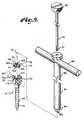
- FIG. 3is a fragmentary and exploded side elevational view of the bone screw, rod and closure with the break-off head of the closure being shown broken therefrom.
- FIG. 4is a fragmentary top plan view of the bone screw, rod and closure with the break-off head removed.
- FIG. 5is a top plan view of the closure with the break-off head broken therefrom, but shown in phantom.
- FIG. 6is a bottom plan view of the closure.
- FIG. 7is an exploded and fragmentary side elevational view of the bone screw, rod and closure showing a removal tool positioned above the closure.
- FIG. 8is a fragmentary and enlarged view of the bone screw, rod and closure shown in FIG. 7 with the removal tool inserted into the closure and with portions of the bone screw and closure broken away to show detail thereof.
- FIG. 9is an exploded perspective view of a modified bone screw and closure in accordance with the present invention, also showing a rod received in a head of the bone screw in phantom lines and a tool for use in inserting the closure into and removing the closure from the head of the bone screw.
- FIG. 10is a side elevational view of the bone screw, rod, closure and tool of the second embodiment of the invention with portions broken away to show internal detail thereof.
- FIG. 11is a fragmentary side elevational view of the bone screw, rod and closure also showing a set screw that is positioned to be received in the closure.
- FIG. 12is a fragmentary side elevational view showing the bone screw, rod, closure and closure set screw positioned in a vertebrae that is shown in cross-section.
- FIG. 13is a front elevational view of the bone screw, rod and closure shown mounted in a vertebrae that is shown in cross-section.
- FIG. 14is a side elevational view of a closure in accordance with a second modified embodiment of the present invention.
- FIG. 15is a top plan view of the closure of the second modified embodiment with a break-off head thereof broken away.
- FIG. 16is a bottom plan view of the closure of the second modified embodiment of the invention.
- the reference numeral 1generally indicates a first embodiment of a medical implant in accordance with the present invention which is shown in FIGS. 1 to 8 .
- the implant 1includes a bone screw 5 , a closure 6 for the bone screw and a rod 7 .
- the implantis received in a vertebrae 9 , typically in conjunction with other implants that are not shown.
- the closure 6also functions in conjunction with other open-headed implants, such as hooks and the like.
- the bone screw 5includes a shank 12 and a head 13 .
- the shank 12is threaded with a coarse flighting-like thread 16 that is threaded into the vertebrae 9 so as to secure and support the bone screw 5 and allow the head 13 to extend from the vertebrae 9 .
- the bone screw head 13includes a base 20 with a pair of upstanding spaced arms 21 and 22 on opposite sides of the base 20 forming a generally U-shaped configuration when viewed from the side and defining a channel 23 therebetween.
- the channel 23is sized and shaped to receive the rod 7 .
- the arms 21 and 22each include an interior threaded surface 26 and 27 respectively.
- the threaded surfaces 26 and 27are spaced and not connected so as to present only a partial threadform which each face one another and cooperate with the closure 6 , as is noted below.
- the threaded surfaces 26 and 27extend from a top 30 of the bone screw only partially down the arms 21 and 22 .
- the closure 6includes a body 35 and a break-off head 36 .
- the closure body 35is generally cylindrical in shape and has a radially outward external threaded surface 40 that extends 360° about an axis of rotation indicated by the reference letter “A”. That is, the threaded surface has a threadform located thereon that entirely encircles the outer threaded surface 40 of the body 35 and extends entirely from top to bottom.
- the threaded surface 40is provided with a thread that is sized, shaped and configured to rotatably mate with the threaded surfaces 26 and 27 of the arms 21 and 22 , so that the closure body 35 may be threaded into the bone screw head, as is shown in FIG. 2 .
- the closure body 35also includes three bores 44 , 45 and 46 that are aligned to be parallel with the axis of rotation.
- the bores 44 , 45 and 46are spaced both from the axis of rotation A and from a periphery 48 of a top 49 of the body.
- the bores 44 , 45 and 46extend from the body top 49 to a bottom surface 50 of the body 35 in the present embodiment.
- the bores 44 , 45 and 46are equally spaced from one another and are approximately equally radially spaced outward from the axis of rotation A. In the embodiment illustrated in FIGS. 1 through 8, the bores 44 , 45 and 46 are spaced at approximately 120° from one another.
- the break-off head 36includes a neck 54 that joins with the body top 49 at a break-off location 56 .
- the break-off location 56is generally coplanar with the body top 49 , so the break-off is clean and low profile.
- the break-off locationis normally determined by the location whereat the neck 54 is smallest in cross-section or can be triggered by an external groove.
- the neck 54also converges somewhat from the remainder of the break-off head 36 to the break-off location 56 .
- the break-off head 36includes a number of facets or panels which are aligned to be parallel to the axis of rotation A and which are joined together to form a polyhedral shape typically associated with a structure to be received in a socket-type tool.
- a combined surface 61 of the facets 60forms such a polyhedral shape.
- a top surface 63 of the break-off head 36has axially located therein a non-threaded bore 65 for operably receiving a tool during implantation.
- the bottom surface 50 of the body 35includes a conical shaped and axially aligned point 67 .
- a tool 70is illustrated in FIG. 2 for cooperatively inserting the closure 6 into the bone screw head 13 .
- the tool 70has an elongate shank 71 with a handle 72 sized and shaped to allow a user to rotate the tool 70 clockwise about the axis of rotation A associated with the closure 6 .
- the tool 70also has a socket type head 74 opposite the handle 72 that is sized and shaped to snugly receive the outer surface 61 of the break off head 36 as is shown in FIG. 2 .
- the rod 7which is elongate and generally circular in cross-section is placed within the bone screw channel 23 and the closure 6 is then threaded into the bone screw head 13 .
- the tool 70is used to rotate the closure 6 until it engages the rod 7 and urges the rod 7 to seat tightly and snugly on the bone screw head base 20 at the bottom of the channel 23 .
- the point 67engages and digs into the rod 7 .
- a preselected torqueis eventually reached (for example 90 inch pounds) where the break-off head 36 breaks from the closure body 35 at the break-off location 56 and separates therefrom, such as is shown in FIG. 3 .
- FIGS. 3 and 4illustrate the closure 6 operably positioned within the bone screw head 13 .
- FIG. 5illustrates the closure 6 with the break-off head 36 removed, but shown in phantom to illustrate the position of the break-off head 36 relative to the bores 44 , 45 and 46 .
- the implant 1is typically a part of an overall system and is normally used to provide support to damaged, injured or missing vertebra of the spinal column.
- the closure 6is removed by utilization of the second tool 78 .
- the tool 78includes a shank 80 that has an axis of rotation during use that is coaxial with the axis of rotation A of the closure 6 .
- the shank 80is attached at one end to a handle 81 to provide a grasp and a means of turning the tool 78 by user.
- the shank 80has a flat surface 83 from which three pegs or posts 84 , 85 and 86 project.
- the posts 84 , 85 and 86are parallel to the axis of rotation of the tool 78 and are sized, shaped and positioned so as to be snugly receivable in the closure bores 44 , 45 and 46 , subsequent to removal of the break-off head 36 .
- the tool 78is shown in position above the closure body 35 in FIG. 7 just prior to insertion of the posts 84 , 85 and 86 into respective bores 44 , 45 and 46 .
- the tool 78is shown positioned with the posts 84 , 85 and 86 in the respective bores 44 , 45 and 46 in FIG. 8 .
- the purpose of the tool 70is to allow user to rotate the closure body 35 counter-clockwise and remove the body 35 from the bone screw head 13 after the closure 6 has been seated therein. In this way the channel 23 can be reopened and the rod 7 removed or repositioned relative to the bone screw head 13 .
- non-axially located bores 44 , 45 and 46 of the present embodimentare located between the break-off head neck 54 and the periphery 48 , it is foreseen that one or more non-axial bores of this type could partially or entirely intersect with the neck 54 so as to become fully open or exposed at the closure top surface 49 only when a break-off head associated with such a neck breaks from the closure body.
- FIGS. 9 to 13Illustrated in FIGS. 9 to 13 is second embodiment or first modified embodiment of an implant in accordance with the present invention that is generally identified by the reference numeral 101 .
- the implant 101includes a bone screw 105 , a closure 106 , a rod 107 and a set screw 108 .
- the bone screw 105 except for the closureis essentially the same as the bone screw 5 and, therefore, will not be described in detail. Reference is made to the description of bone screw 5 for additional detail.
- the bone screw 105has a shank 112 and a head 113 . Upright arms 121 and 122 of the head 113 have inner or interior facing and threaded surfaces 126 and 127 .
- the rod 107is elongate and has a generally circular cross section for being received in the head 113 beneath the closure 106 .
- the closure 106is similar in some respects to the closure 6 , but is installed in a different manner.
- the closure 106has a generally cylindrical shaped body 135 that has a threaded radially outward surface 140 that has a thread thereon that is sized, shaped and positioned to threadedly mate with threads of the arm threaded surfaces 126 and 127 , as seen in FIG. 10 .
- the threadcan be a conventional V-thread, a buttress thread, a reverse angle thread or other threads related to reverse angle threads in that they exert forces to draw or pull the arms 121 and 122 toward one another rather than cause them to splay or open at the top.
- the body 135also has a top surface 149 and a bottom surface 150 . Positioned to extend downwardly into the body 135 form the top surface 149 are four equally spaced bores 151 , 152 , 153 and 154 that do not extend entirely through the body 135 from top to bottom.
- the bores 151 , 152 , 153 and 154are spaced form and positioned between both a central axis B and a periphery 158 of the body top surface 149 .
- Each bore 151 , 152 , 153 and 154is positioned at approximately 90° relative to adjacent bores 151 , 152 , 153 and 154 .
- a threaded bore 161Located axially and centrally in the body 135 is a threaded bore 161 .
- the threaded bore 161extends between the top surface 149 and bottom surface 150 .
- the set screw 108has a threaded shaft 170 sized and shaped to be threadably received in the body threaded bore 161 .
- the set screw 170has sufficient length to extend through and outward from the bottom surface 150 .
- the set screw 108has a head 171 that is gripable by a tool for rotation and torquing.
- a tool 180is provided for installing and removing the closure 106 form the bone screw head 113 .
- the tool 180is T-shaped having a shank 181 with a handle 182 attached to one end and a generally flat surface 184 at an opposite end.
- the surface 184has four pegs or posts 186 extending therefrom.
- the posts 186extend form the surface 184 parallel to an axis of rotation of the tool 180 which is the same in use as the axis of rotation B of the closure.
- the posts 186are aligned, sized and shaped to mate with the closure body bores 151 , 152 , 153 and 154 .
- the tool shank 170also includes an axial bore extending therethrough and receiving a keeper rod 190 .
- the rod 190has a threaded tip 191 that is adapted to be received in the closure body bore 161 and a grasping head 192 at an opposite end.
- the rod 107is placed in the head 112 and the tool 180 is mated with the closure 106 in the manner shown in FIG. 10, so that the four posts 186 are located in respective bores 151 , 152 , 152 and 154 and the rod tip 191 is threaded into the threaded bore 161 .
- the closure 106is then mated with the head 112 and threaded thereon by mating of the surface 140 with the arm surfaces 126 and 127 until the closure 106 is snug in the bone screw head 113 . Torque in a preselected amount is applied to the closure 106 to ensure it is tightly seated in the head 112 .
- the closure 106may just be used to capture the rod 107 and the set screw 108 is used to lock the rod 107 in place.
- the tool 180may be removed and the set screw 108 is then placed in the bore 161 and advanced against the rod 107 .
- a preselected torqueis applied to lock the rod 107 in a selected position in the head 112 .
- the set screw 108may be of other types than the one illustrated. That is the set screw could have a break-off head in which case the overall implant 101 would have a comparatively low profile associated with only the top of the bone screw.
- the installation processis reversed. That is the tool 180 is utilized to rotate the closure 106 counterclockwise rather than the clockwise direction used for inserting. Where a break off set screw is used, the set screw can be rotated with the body 135 of the closure 106 for removal.
- FIGS. 14, 15 and 16Illustrated in FIGS. 14, 15 and 16 is a third embodiment or second modified embodiment of a bone screw closure in accordance with the present invention and generally identified by the reference numeral 206 .
- closure 206is in many ways similar to the closure 6 and reference is made to the disclosure for the closure 6 for additional detail.
- the closure 206has a generally cylindrically shaped body 235 that has a radially outer threaded surface 240 .
- the closure 235also has a break-off head 236 secured to a top or upper surface 249 of the body 235 by a neck 254 at a break-off location 256 .
- a neck 254Positioned between the neck 254 and a periphery 248 of the body upper surface 249 are three bores 244 , 245 and 246 that extend parallel to a central axis of rotation identified by a reference numeral C.
- a body 235 thereofalso includes a central or axial bore 260 extending from a bottom surface 250 upward through the body 235 to the level of an upper surface 249 of the body 235 .
- the bore 260is threaded and covered by the neck 254 until the break-off head 236 breaks form the body 235 during installation by application of torque, as was described in the first embodiment.
- the bore 260is thereafter exposed upwardly or at the upper surface 249 and adapted to receive a set screw 263 of the type used in the second embodiment or alternatively a break-off type, as shown, set screw having removal slots 264 . It is noted that the diameter of the neck 254 at the top surface 249 is larger than the diameter of the bore 260 .
Landscapes
- Health & Medical Sciences (AREA)
- Orthopedic Medicine & Surgery (AREA)
- Life Sciences & Earth Sciences (AREA)
- Neurology (AREA)
- Surgery (AREA)
- Heart & Thoracic Surgery (AREA)
- Engineering & Computer Science (AREA)
- Biomedical Technology (AREA)
- Nuclear Medicine, Radiotherapy & Molecular Imaging (AREA)
- Medical Informatics (AREA)
- Molecular Biology (AREA)
- Animal Behavior & Ethology (AREA)
- General Health & Medical Sciences (AREA)
- Public Health (AREA)
- Veterinary Medicine (AREA)
- Prostheses (AREA)
- Surgical Instruments (AREA)
Abstract
Description
The present invention is directed to an open headed medical implant and, in particular, to a closure for closing the head of an open headed bone screw, hook or the like.
Bone screws are used especially in spinal surgery to support and position various implants needed to repair a spine that has suffered injury, illness or genetic defect. Bone screws of this type are screwed into the vertebrae of the spine and have a head that projects outside the bone which receives other implants, such as rods, that extend along the spine. Bone screws are of two general types which are either open headed or closed headed. Hooks and certain other implants also sometimes have open heads. The present application is directed to open headed bone screws and related implants such as hooks and the like that have such an open head to receive another implant.
In open headed bone screws and related implants, the head includes two upright arms that form a channel therebetween. The channel is sized to receive a rod or the like and is open to make it easier to place the rod in the head. The rod must then be tightly held or locked in the head to prevent relative movement between implants after the surgery. To hold the rod in the head, plugs have been used that are screwed into threads on the interior surfaces of the arms.
The present invention is directed especially to improvements in such plugs or closures that make them easier to insert in the head, that better ensure that the plug effectively secures the rod so that the rod does not later slip, that allow the plugs to be easily removed should the overall implant system require rearrangement and which provide a comparatively low profile, so as reduce trauma and irritation to the surrounding tissues of the patient.
A closure is provided for an open headed implant, especially a bone screw or hook for use in spinal surgery. The closure has a cylindrical shaped body with an axis of rotation. The body has a radially outer surface that is threaded with a thread that is sized and shaped to be received in mating threads on interior surfaces of arms of the implant head. The closure is operably threaded into the head of the implant to capture a rod or other part of an overall spinal support system. The closure captures and locks such a rod in position relative to the implant to prevent rotation or axial movement between the joined parts.
The closure body has a top surface and a bottom surface with a plurality of bores extending parallel to the axis of rotation into the body from the top surface. The bores are positioned in spaced relationship to one another and to the axis of rotation. The bores are sized and shaped to cooperatively mate with posts on a tool to allow removal of the closure from the implant after insertion, should such be necessary. In some instances the tool may also be used to install the closure in the implant.
In one embodiment the closure also includes a break-off head centrally mounted by a neck on the top surface of the body. The break-off head is adapted to receive a socket tool and be rotated thereby during installation. The break-off head is also designed to break from the body at a break-off point or location which is preferably whereat the neck intersects with the top surface of the body; when a preselected torque is applied to the break-off head. When the break-off head is broken away, the bores that are adapted to mate with a removal tool become exposed.
In a second embodiment the body includes a central threaded bore that receives a set screw. The body is then used for capture of a rod or the like and the set screw is used to lock the rod or the like in position relative to the implant.
In a third embodiment, a body includes both a break-off head and a central threaded bore that is covered by the break-off head until the head breaks away, after which the threaded bore is exposed at the top surface of the body to receive a set screw.
Therefore, the objects of the present invention are: to provide a closure for an open ended implant that provides a plurality of spaced bores that are offset from an axis of rotation of the closure and that cooperate with a tool to allow removal of the closure; to provide such an implant having a closure with a break off head for mating with an insertion tool for inserting the closure into the implant; to provide such an implant wherein the removal bores are not accessible for effective access, when the closure is in the implant until the break-off head is broken away; to provide such an implant having a closure wherein a closure body has an axially centered threaded bore and including a set screw sized and shaped to be threaded into and extend from the bottom of the closure threaded bore when fully inserted therein; to provide such an implant having a break-off head joined by a neck to a body of the closure and centered on a top of the closure with the body also having a central threaded bore that extends from a bottom to the top of the closure body, but the threaded bore is unaccessible at the top of the body until the break-off head breaks from the body; to provide such an implant that strongly grips a rod or the like received in the implant and that provides a relatively low profile; and to provide such an implant and closure therefore that is relatively easy to use, comparatively easy to produce and is especially well suited for the intended use thereof.
Other objects and advantages of this invention will become apparent from the following description taken in conjunction with the accompanying drawings wherein are set forth, by way of illustration and example, certain embodiments of this invention.
The drawings constitute a part of this specification and include exemplary embodiments of the present invention and illustrate various objects and features thereof.
FIG. 1 is an exploded perspective view of a bone screw type implant and closure cap in accordance with the present invention prior to insertion of the closure cap into a head of the bone screw.
FIG. 2 is a fragmentary side elevational view of the bone screw with a rod and the closure received therein and with a tool being utilized to insert the closure and provide torque to the break-off head of the closure and further with the bone screw shown embedded in a bone that is indicated by phantom lines.
FIG. 3 is a fragmentary and exploded side elevational view of the bone screw, rod and closure with the break-off head of the closure being shown broken therefrom.
FIG. 4 is a fragmentary top plan view of the bone screw, rod and closure with the break-off head removed.
FIG. 5 is a top plan view of the closure with the break-off head broken therefrom, but shown in phantom.
FIG. 6 is a bottom plan view of the closure.
FIG. 7 is an exploded and fragmentary side elevational view of the bone screw, rod and closure showing a removal tool positioned above the closure.
FIG. 8 is a fragmentary and enlarged view of the bone screw, rod and closure shown in FIG. 7 with the removal tool inserted into the closure and with portions of the bone screw and closure broken away to show detail thereof.
FIG. 9 is an exploded perspective view of a modified bone screw and closure in accordance with the present invention, also showing a rod received in a head of the bone screw in phantom lines and a tool for use in inserting the closure into and removing the closure from the head of the bone screw.
FIG. 10 is a side elevational view of the bone screw, rod, closure and tool of the second embodiment of the invention with portions broken away to show internal detail thereof.
FIG. 11 is a fragmentary side elevational view of the bone screw, rod and closure also showing a set screw that is positioned to be received in the closure.
FIG. 12 is a fragmentary side elevational view showing the bone screw, rod, closure and closure set screw positioned in a vertebrae that is shown in cross-section.
FIG. 13 is a front elevational view of the bone screw, rod and closure shown mounted in a vertebrae that is shown in cross-section.
FIG. 14 is a side elevational view of a closure in accordance with a second modified embodiment of the present invention.
FIG. 15 is a top plan view of the closure of the second modified embodiment with a break-off head thereof broken away.
FIG. 16 is a bottom plan view of the closure of the second modified embodiment of the invention.
As required, detailed embodiments of the present invention are disclosed herein; however, it is to be understood that the disclosed embodiments are merely exemplary of the invention, which may be embodied in various forms. Therefore, specific structural and functional details disclosed herein are not to be interpreted as limiting, but merely as a basis for the claims and as a representative basis for teaching one skilled in the art to variously employ the present invention in virtually any appropriately detailed structure.
The reference numeral1 generally indicates a first embodiment of a medical implant in accordance with the present invention which is shown in FIGS. 1 to8. The implant1 includes abone screw 5, aclosure 6 for the bone screw and arod 7. The implant is received in a vertebrae9, typically in conjunction with other implants that are not shown. Theclosure 6 also functions in conjunction with other open-headed implants, such as hooks and the like.
Thebone screw 5 includes ashank 12 and ahead 13. Theshank 12 is threaded with a coarse flighting-like thread16 that is threaded into the vertebrae9 so as to secure and support thebone screw 5 and allow thehead 13 to extend from the vertebrae9.
Thebone screw head 13 includes abase 20 with a pair of upstanding spacedarms base 20 forming a generally U-shaped configuration when viewed from the side and defining achannel 23 therebetween. Thechannel 23 is sized and shaped to receive therod 7.
Thearms surface surfaces closure 6, as is noted below. In the illustrated embodiment, the threadedsurfaces top 30 of the bone screw only partially down thearms
Theclosure 6 includes abody 35 and a break-offhead 36. In the present embodiment shown in FIGS. 1 through 8 theclosure body 35 is generally cylindrical in shape and has a radially outward external threadedsurface 40 that extends 360° about an axis of rotation indicated by the reference letter “A”. That is, the threaded surface has a threadform located thereon that entirely encircles the outer threadedsurface 40 of thebody 35 and extends entirely from top to bottom. The threadedsurface 40 is provided with a thread that is sized, shaped and configured to rotatably mate with the threaded surfaces26 and27 of thearms closure body 35 may be threaded into the bone screw head, as is shown in FIG.2.
Theclosure body 35 also includes threebores bores periphery 48 of a top49 of the body. Thebores body top 49 to abottom surface 50 of thebody 35 in the present embodiment. Preferably thebores bores
The break-offhead 36 includes aneck 54 that joins with thebody top 49 at a break-offlocation 56. Preferably the break-offlocation 56 is generally coplanar with thebody top 49, so the break-off is clean and low profile. The break-off location is normally determined by the location whereat theneck 54 is smallest in cross-section or can be triggered by an external groove. Theneck 54 also converges somewhat from the remainder of the break-offhead 36 to the break-offlocation 56.
The break-offhead 36 includes a number of facets or panels which are aligned to be parallel to the axis of rotation A and which are joined together to form a polyhedral shape typically associated with a structure to be received in a socket-type tool. A combinedsurface 61 of thefacets 60 forms such a polyhedral shape. Atop surface 63 of the break-offhead 36 has axially located therein anon-threaded bore 65 for operably receiving a tool during implantation. Thebottom surface 50 of thebody 35 includes a conical shaped and axially alignedpoint 67.
Atool 70 is illustrated in FIG. 2 for cooperatively inserting theclosure 6 into thebone screw head 13. Thetool 70 has an elongate shank71 with ahandle 72 sized and shaped to allow a user to rotate thetool 70 clockwise about the axis of rotation A associated with theclosure 6. Thetool 70 also has asocket type head 74 opposite thehandle 72 that is sized and shaped to snugly receive theouter surface 61 of the break offhead 36 as is shown in FIG.2.
During assembly, therod 7 which is elongate and generally circular in cross-section is placed within thebone screw channel 23 and theclosure 6 is then threaded into thebone screw head 13. Thetool 70 is used to rotate theclosure 6 until it engages therod 7 and urges therod 7 to seat tightly and snugly on the bonescrew head base 20 at the bottom of thechannel 23. Thepoint 67 engages and digs into therod 7. As additional torque is applied to thetool 70, a preselected torque is eventually reached (for example 90 inch pounds) where the break-offhead 36 breaks from theclosure body 35 at the break-offlocation 56 and separates therefrom, such as is shown in FIG.3.
FIGS. 3 and 4 illustrate theclosure 6 operably positioned within thebone screw head 13. FIG. 5 illustrates theclosure 6 with the break-offhead 36 removed, but shown in phantom to illustrate the position of the break-offhead 36 relative to thebores
In certain circumstances, it is necessary to remove theclosure 6 to readjust the position of therod 7 or to make some other change in the implant configuration. As mentioned before, the implant1 is typically a part of an overall system and is normally used to provide support to damaged, injured or missing vertebra of the spinal column. When it is necessary to readjust the system, theclosure 6 is removed by utilization of thesecond tool 78. Thetool 78 includes ashank 80 that has an axis of rotation during use that is coaxial with the axis of rotation A of theclosure 6. Theshank 80 is attached at one end to ahandle 81 to provide a grasp and a means of turning thetool 78 by user. Opposite thehandle 81, theshank 80 has aflat surface 83 from which three pegs orposts posts tool 78 and are sized, shaped and positioned so as to be snugly receivable in the closure bores44,45 and46, subsequent to removal of the break-offhead 36. Thetool 78 is shown in position above theclosure body 35 in FIG. 7 just prior to insertion of theposts respective bores tool 78 is shown positioned with theposts tool 70 is to allow user to rotate theclosure body 35 counter-clockwise and remove thebody 35 from thebone screw head 13 after theclosure 6 has been seated therein. In this way thechannel 23 can be reopened and therod 7 removed or repositioned relative to thebone screw head 13.
While the non-axially located bores44,45 and46 of the present embodiment are located between the break-offhead neck 54 and theperiphery 48, it is foreseen that one or more non-axial bores of this type could partially or entirely intersect with theneck 54 so as to become fully open or exposed at the closuretop surface 49 only when a break-off head associated with such a neck breaks from the closure body.
Illustrated in FIGS. 9 to13 is second embodiment or first modified embodiment of an implant in accordance with the present invention that is generally identified by the reference numeral101. The implant101 includes abone screw 105, aclosure 106, arod 107 and aset screw 108.
Thebone screw 105 except for the closure is essentially the same as thebone screw 5 and, therefore, will not be described in detail. Reference is made to the description ofbone screw 5 for additional detail. Thebone screw 105 has ashank 112 and ahead 113.Upright arms head 113 have inner or interior facing and threadedsurfaces
Therod 107 is elongate and has a generally circular cross section for being received in thehead 113 beneath theclosure 106.
Theclosure 106 is similar in some respects to theclosure 6, but is installed in a different manner. In particular, theclosure 106 has a generally cylindrical shapedbody 135 that has a threaded radiallyoutward surface 140 that has a thread thereon that is sized, shaped and positioned to threadedly mate with threads of the arm threadedsurfaces arms
Thebody 135 also has atop surface 149 and abottom surface 150. Positioned to extend downwardly into thebody 135 form thetop surface 149 are four equally spaced bores151,152,153 and154 that do not extend entirely through thebody 135 from top to bottom. Thebores periphery 158 of the bodytop surface 149. Eachbore adjacent bores
Located axially and centrally in thebody 135 is a threadedbore 161. The threaded bore161 extends between thetop surface 149 andbottom surface 150.
Theset screw 108 has a threaded shaft170 sized and shaped to be threadably received in the body threaded bore161. The set screw170 has sufficient length to extend through and outward from thebottom surface 150. In the second embodiment theset screw 108 has a head171 that is gripable by a tool for rotation and torquing.
A tool180 is provided for installing and removing theclosure 106 form thebone screw head 113. The tool180 is T-shaped having a shank181 with a handle182 attached to one end and a generally flat surface184 at an opposite end. The surface184 has four pegs or posts186 extending therefrom. The posts186 extend form the surface184 parallel to an axis of rotation of the tool180 which is the same in use as the axis of rotation B of the closure. The posts186 are aligned, sized and shaped to mate with the closure body bores151,152,153 and154.
The tool shank170 also includes an axial bore extending therethrough and receiving a keeper rod190. The rod190 has a threaded tip191 that is adapted to be received in the closure body bore161 and a grasping head192 at an opposite end.
In use therod 107 is placed in thehead 112 and the tool180 is mated with theclosure 106 in the manner shown in FIG. 10, so that the four posts186 are located inrespective bores bore 161. Theclosure 106 is then mated with thehead 112 and threaded thereon by mating of thesurface 140 with the arm surfaces126 and127 until theclosure 106 is snug in thebone screw head 113. Torque in a preselected amount is applied to theclosure 106 to ensure it is tightly seated in thehead 112. In some instances, theclosure 106 may just be used to capture therod 107 and theset screw 108 is used to lock therod 107 in place. In particular, the tool180 may be removed and theset screw 108 is then placed in thebore 161 and advanced against therod 107. A preselected torque is applied to lock therod 107 in a selected position in thehead 112.
It is foreseen that theset screw 108 may be of other types than the one illustrated. That is the set screw could have a break-off head in which case the overall implant101 would have a comparatively low profile associated with only the top of the bone screw.
For removal, the installation process is reversed. That is the tool180 is utilized to rotate theclosure 106 counterclockwise rather than the clockwise direction used for inserting. Where a break off set screw is used, the set screw can be rotated with thebody 135 of theclosure 106 for removal.
Illustrated in FIGS. 14,15 and16 is a third embodiment or second modified embodiment of a bone screw closure in accordance with the present invention and generally identified by thereference numeral 206.
Theclosure 206 is in many ways similar to theclosure 6 and reference is made to the disclosure for theclosure 6 for additional detail.
In particular theclosure 206 has a generally cylindrically shapedbody 235 that has a radially outer threadedsurface 240. Theclosure 235 also has a break-offhead 236 secured to a top orupper surface 249 of thebody 235 by aneck 254 at a break-offlocation 256. Positioned between theneck 254 and aperiphery 248 of the bodyupper surface 249 are threebores
The major difference between the present embodiment and theclosure 6 shown in the first embodiment is that abody 235 thereof also includes a central oraxial bore 260 extending from abottom surface 250 upward through thebody 235 to the level of anupper surface 249 of thebody 235. Thebore 260 is threaded and covered by theneck 254 until the break-offhead 236 breaks form thebody 235 during installation by application of torque, as was described in the first embodiment. Thebore 260 is thereafter exposed upwardly or at theupper surface 249 and adapted to receive aset screw 263 of the type used in the second embodiment or alternatively a break-off type, as shown, set screw having removal slots264. It is noted that the diameter of theneck 254 at thetop surface 249 is larger than the diameter of thebore 260.
It is to be understood that while certain forms of the present invention have been illustrated and described herein, it is not to be limited to the specific forms or arrangement of parts described and shown.
Claims (13)
1. An open-headed medical implant having:
a) a first element adapted to operably be joined to a bone or other implant;
b) an implant head secured to said first element and having a pair of upright spaced arms defining a channel therebetween; said arms each having facing interior threaded surfaces;
c) a plug for closing said channel between said arms; said plug comprising:
i) a body sized and shaped to be received between the arms of said head; said body having a radially outward surface that has a thread thereon that is sized and shaped to threadedly mate with the threaded arms of said head;
ii) said body having a top and a bottom; said top of said body having at least one bore therein sized and shaped to receive a tool and extending generally axially at least partially through said body from top to bottom thereof; and wherein:
iii) said bore is spaced from and positioned between both a central axis of said body and a periphery of said body.
2. The implant according toclaim 1 wherein:
a) there are a pair of spaced bores extending into said body from the top surface thereof.
3. The implant according toclaim 1 wherein:
a) said body is generally cylindrical in shape.
4. The implant according toclaim 1 including:
a) a break-off head joined to said body by a neck; said neck being aligned with the central axis of said body.
5. The implant according toclaim 4 wherein:
a) said body includes at least a pair of said bores in the top thereof; and
b) said neck is positioned between said bores.
6. The implant according toclaim 4 wherein:
a) said break-off head has a tool gripable outer surface for operably rotating said closure during insertion into said implant head and said neck being sized and shaped such that said break-off head breaks from said body when a preselected torque is applied to said break-off head by such a gripping tool with a generally clean profile at said top surface.
7. The implant according toclaim 4 wherein:
a) said body includes an axial extending bore from the bottom to near the top thereof; said axial bore being located beneath said neck and being accessible from the top of said body when said break-off head breaks away from said body.
8. The implant according toclaim 7 wherein:
a) said axial bore is threaded.
9. The implant according toclaim 1 wherein:
a) said closure includes an axial threaded bore passing entirely through said body from a top to a bottom thereof.
10. The implant according toclaim 9 in combination with:
a) a threaded set screw sized and shaped to be received in said axial bore; said axial set screw being also sized and shaped to extend outward from said body bottom surface when said screw is fully installed therein.
11. The implant according toclaim 1 wherein:
a) said body top surface has three spaced tool receiving bores located therein; each of said bores being located at a common radius from said body central axis and being spaced at 120° from adjacent tool receiving bores.
12. The implant according toclaim 1 wherein:
a) said body top has four spaced tool receiving bores each being located at a common radius from said body central axis and being evenly spaced from adjacent tool receiving bores.
13. The implant according toclaim 1 including:
a) a tool having a gripable handle and an engagement face; said face including a post extending parallel to an axis of rotation of said tool for each said body bore; each said post being sized, aligned and positional to simultaneously enter a respective bore so as to rotate and apply torque to said body when said tool is rotated about the axis thereof, whereby said tool is operable to at least remove said body from said implant head in which said body has been inserted.
Priority Applications (17)
| Application Number | Priority Date | Filing Date | Title |
|---|---|---|---|
| US10/014,434US6726687B2 (en) | 2000-12-08 | 2001-11-09 | Closure plug for open-headed medical implant |
| US10/142,614US8377100B2 (en) | 2000-12-08 | 2002-05-09 | Closure for open-headed medical implant |
| CA002466417ACA2466417C (en) | 2001-11-09 | 2002-10-28 | Closure plug for open-headed medical implant |
| EP02803168AEP1450705B1 (en) | 2001-11-09 | 2002-10-28 | Closure plug for open-headed medical implant |
| AU2002363787AAU2002363787B2 (en) | 2001-11-09 | 2002-10-28 | Closure plug for open-headed medical implant |
| PCT/US2002/034457WO2003041599A1 (en) | 2001-11-09 | 2002-10-28 | Closure plug for open-headed medical implant |
| ES02803168TES2388135T3 (en) | 2001-11-09 | 2002-10-28 | Closing cap for medical implant with open head |
| JP2003543487AJP2005508694A (en) | 2001-11-09 | 2002-10-28 | Closed body plug for open head medical implants |
| US10/767,646US7846187B2 (en) | 2000-12-08 | 2004-01-29 | Closure plug for open headed medical implant |
| US10/783,236US6997927B2 (en) | 2000-12-08 | 2004-02-20 | closure for rod receiving orthopedic implant having a pair of spaced apertures for removal |
| JP2007003890UJP3135102U (en) | 2001-11-09 | 2007-05-28 | Closed body plug for open head medical implants |
| US13/694,970US20130144347A1 (en) | 2000-12-08 | 2013-01-23 | Closure for open headed implant |
| US14/509,496US20150025580A1 (en) | 2000-12-08 | 2014-10-08 | Closure for open-headed medical implant |
| US15/144,915US9907577B2 (en) | 2000-12-08 | 2016-05-03 | Closure for open-headed medical implant |
| US15/883,993US10004541B1 (en) | 2000-12-08 | 2018-01-30 | Closure for open-headed medical implant |
| US16/016,212US10993745B2 (en) | 2000-12-08 | 2018-06-22 | Threaded closure mechanism having a closed body with inwardly-facing concave radiused tool engaging surfaces and a downwardly extending rod-engaging structure |
| US16/789,266US10925647B2 (en) | 2000-12-08 | 2020-02-12 | Threaded closure with inwardly-facing tool engaging concave radiused structures and axial through-aperture |
Applications Claiming Priority (2)
| Application Number | Priority Date | Filing Date | Title |
|---|---|---|---|
| US09/732,528US6454772B1 (en) | 2000-12-08 | 2000-12-08 | Set screw for medical implant with gripping side slots |
| US10/014,434US6726687B2 (en) | 2000-12-08 | 2001-11-09 | Closure plug for open-headed medical implant |
Related Parent Applications (1)
| Application Number | Title | Priority Date | Filing Date |
|---|---|---|---|
| US09/732,528Continuation-In-PartUS6454772B1 (en) | 2000-12-08 | 2000-12-08 | Set screw for medical implant with gripping side slots |
Related Child Applications (4)
| Application Number | Title | Priority Date | Filing Date |
|---|---|---|---|
| US10/142,614Continuation-In-PartUS8377100B2 (en) | 2000-12-08 | 2002-05-09 | Closure for open-headed medical implant |
| US10/236,123Continuation-In-PartUS6726689B2 (en) | 2000-12-08 | 2002-09-06 | Helical interlocking mating guide and advancement structure |
| US10/236,123ContinuationUS6726689B2 (en) | 2000-12-08 | 2002-09-06 | Helical interlocking mating guide and advancement structure |
| US10/767,646DivisionUS7846187B2 (en) | 2000-12-08 | 2004-01-29 | Closure plug for open headed medical implant |
Publications (2)
| Publication Number | Publication Date |
|---|---|
| US20020072751A1 US20020072751A1 (en) | 2002-06-13 |
| US6726687B2true US6726687B2 (en) | 2004-04-27 |
Family
ID=21765468
Family Applications (2)
| Application Number | Title | Priority Date | Filing Date |
|---|---|---|---|
| US10/014,434Expired - LifetimeUS6726687B2 (en) | 2000-12-08 | 2001-11-09 | Closure plug for open-headed medical implant |
| US10/767,646Expired - Fee RelatedUS7846187B2 (en) | 2000-12-08 | 2004-01-29 | Closure plug for open headed medical implant |
Family Applications After (1)
| Application Number | Title | Priority Date | Filing Date |
|---|---|---|---|
| US10/767,646Expired - Fee RelatedUS7846187B2 (en) | 2000-12-08 | 2004-01-29 | Closure plug for open headed medical implant |
Country Status (7)
| Country | Link |
|---|---|
| US (2) | US6726687B2 (en) |
| EP (1) | EP1450705B1 (en) |
| JP (2) | JP2005508694A (en) |
| AU (1) | AU2002363787B2 (en) |
| CA (1) | CA2466417C (en) |
| ES (1) | ES2388135T3 (en) |
| WO (1) | WO2003041599A1 (en) |
Cited By (102)
| Publication number | Priority date | Publication date | Assignee | Title |
|---|---|---|---|---|
| US20030100896A1 (en)* | 2001-11-27 | 2003-05-29 | Lutz Biedermann | Element with a shank and a holding element connected to it for connecting to a rod |
| US20030153911A1 (en)* | 2002-02-13 | 2003-08-14 | Endius Incorporated | Apparatus for connecting a longitudinal member to a bone portion |
| US20040172020A1 (en)* | 2001-04-06 | 2004-09-02 | Jacques Beaurain | Spinal osteosynthesis device and preparation method |
| US20040193176A1 (en)* | 2003-02-12 | 2004-09-30 | Heinz Gerngross | Implant removal |
| US20040254577A1 (en)* | 2001-10-18 | 2004-12-16 | Joel Delecrin | Progressive approach osteosynthesis device and preassembly method |
| US20050010215A1 (en)* | 2001-10-18 | 2005-01-13 | Joel Delecrin | Plate for osteosynthesis device and preassembling method |
| US20050048775A1 (en)* | 2001-07-19 | 2005-03-03 | Hilke Donohue | Depositing a tantalum film |
| US20050107788A1 (en)* | 2001-12-12 | 2005-05-19 | Jacques Beaurain | Implant for osseous anchoring with polyaxial head |
| US20050187549A1 (en)* | 2000-06-06 | 2005-08-25 | Jackson Roger P. | Removable medical implant closure |
| US20050267477A1 (en)* | 2000-06-06 | 2005-12-01 | Jackson Roger P | Removable medical implant closure |
| US20060241599A1 (en)* | 2003-06-27 | 2006-10-26 | Konieczynski David D | Polyaxial Bone Screw |
| US20060241602A1 (en)* | 2000-06-06 | 2006-10-26 | Jackson Roger P | Hooked transverse connector for spinal implant system |
| US20060276791A1 (en)* | 2002-02-13 | 2006-12-07 | Shluzas Alan E | Methods for connecting a longitudinal member to a bone portion |
| US20070118123A1 (en)* | 2005-11-21 | 2007-05-24 | Strausbaugh William L | Polyaxial bone anchors with increased angulation |
| US20070167949A1 (en)* | 2004-10-20 | 2007-07-19 | Moti Altarac | Screw systems and methods for use in stabilization of bone structures |
| US20070255284A1 (en)* | 2006-04-28 | 2007-11-01 | Sdgi Holdings, Inc. | Orthopedic implant apparatus |
| US20070270811A1 (en)* | 2006-04-14 | 2007-11-22 | Sdgi Holdings, Inc. | Reducing device |
| US20070270859A1 (en)* | 2006-04-28 | 2007-11-22 | Sdgi Holdings, Inc. | Orthopedic screw with break away drive |
| US20080015580A1 (en)* | 2006-04-28 | 2008-01-17 | Nam Chao | Large diameter bone anchor assembly |
| US20080015584A1 (en)* | 2002-04-18 | 2008-01-17 | Aesculap Implant Systems | Screw and rod fixation assembly and device |
| US20080234766A1 (en)* | 2007-01-29 | 2008-09-25 | Polaris Biotechnology, Inc. | Craniospinal fusion method and apparatus |
| US20080275456A1 (en)* | 2007-05-02 | 2008-11-06 | Zimmer Spine, Inc. | Installation systems for spinal stabilization system and related methods |
| US20090018584A1 (en)* | 2007-01-29 | 2009-01-15 | Polaris Biotechnology, Inc. | Vertebra attachment method and system |
| US20090036894A1 (en)* | 2007-01-29 | 2009-02-05 | Polaris Biotechnology, Inc. | Method of treating a neurological condition through correction and stabilization of the clivo-axial angle |
| US20090163955A1 (en)* | 2007-12-19 | 2009-06-25 | Missoum Moumene | Polymeric Pedicle Rods and Methods of Manufacturing |
| US20090177230A1 (en)* | 2008-01-08 | 2009-07-09 | Polaris Biotechnology, Inc. | Osteointegration apparatus |
| US20090275246A1 (en)* | 2008-04-30 | 2009-11-05 | Cooper Technologies Company | Single pole cable connector with tamper resistant locking mechanism |
| US20090326583A1 (en)* | 2008-06-25 | 2009-12-31 | Missoum Moumene | Posterior Dynamic Stabilization System With Flexible Ligament |
| US20090326584A1 (en)* | 2008-06-27 | 2009-12-31 | Michael Andrew Slivka | Spinal Dynamic Stabilization Rods Having Interior Bumpers |
| US20100152575A1 (en)* | 2008-01-08 | 2010-06-17 | Polaris Biotechnology, Inc. | Mathematical Relationship of Strain, Neurological Dysfunction and Abnormal Behavior Resulting from Neurological Dysfunction of the Brainstem |
| US20100179597A1 (en)* | 2007-01-29 | 2010-07-15 | Polaris Biotechnology, Inc. | Craniospinal fusion method and apparatus |
| US20100211104A1 (en)* | 2009-02-13 | 2010-08-19 | Missoum Moumene | Dual Spring Posterior Dynamic Stabilization Device With Elongation Limiting Elastomers |
| US20100241175A1 (en)* | 2009-03-20 | 2010-09-23 | Spinal USA LLC | Pedicle screws and methods of using the same |
| US20100316439A1 (en)* | 2009-04-03 | 2010-12-16 | Jergens, Inc. | Mounting system |
| US20100331886A1 (en)* | 2009-06-25 | 2010-12-30 | Jonathan Fanger | Posterior Dynamic Stabilization Device Having A Mobile Anchor |
| US7927359B2 (en) | 2005-10-06 | 2011-04-19 | Paradigm Spine, Llc | Polyaxial screw |
| US8007522B2 (en) | 2008-02-04 | 2011-08-30 | Depuy Spine, Inc. | Methods for correction of spinal deformities |
| US20110238119A1 (en)* | 2010-03-24 | 2011-09-29 | Missoum Moumene | Composite Material Posterior Dynamic Stabilization Spring Rod |
| US8096996B2 (en) | 2007-03-20 | 2012-01-17 | Exactech, Inc. | Rod reducer |
| US8202304B2 (en) | 2002-08-21 | 2012-06-19 | Theken Spine, Llc | Methods and systems for performing spinal surgery |
| US8226690B2 (en) | 2005-07-22 | 2012-07-24 | The Board Of Trustees Of The Leland Stanford Junior University | Systems and methods for stabilization of bone structures |
| US8282673B2 (en) | 2002-09-06 | 2012-10-09 | Jackson Roger P | Anti-splay medical implant closure with multi-surface removal aperture |
| US8343219B2 (en) | 2007-06-08 | 2013-01-01 | Ldr Medical | Intersomatic cage, intervertebral prosthesis, anchoring device and implantation instruments |
| US8361123B2 (en) | 2009-10-16 | 2013-01-29 | Depuy Spine, Inc. | Bone anchor assemblies and methods of manufacturing and use thereof |
| US8388659B1 (en) | 2008-10-17 | 2013-03-05 | Theken Spine, Llc | Spondylolisthesis screw and instrument for implantation |
| US8523865B2 (en) | 2005-07-22 | 2013-09-03 | Exactech, Inc. | Tissue splitter |
| US8534658B2 (en) | 2009-04-03 | 2013-09-17 | Jergens, Inc. | Mounting system |
| US8845649B2 (en) | 2004-09-24 | 2014-09-30 | Roger P. Jackson | Spinal fixation tool set and method for rod reduction and fastener insertion |
| US8845691B2 (en) | 2003-09-01 | 2014-09-30 | Ldr Medical | Osseous anchoring implant with a polyaxial head and method for installing the implant |
| US8894657B2 (en) | 2004-02-27 | 2014-11-25 | Roger P. Jackson | Tool system for dynamic spinal implants |
| US20150025580A1 (en)* | 2000-12-08 | 2015-01-22 | Roger P. Jackson | Closure for open-headed medical implant |
| US8956361B2 (en) | 2011-12-19 | 2015-02-17 | Amendia, Inc. | Extended tab bone screw system |
| US9050148B2 (en) | 2004-02-27 | 2015-06-09 | Roger P. Jackson | Spinal fixation tool attachment structure |
| US9050139B2 (en) | 2004-02-27 | 2015-06-09 | Roger P. Jackson | Orthopedic implant rod reduction tool set and method |
| US9055978B2 (en) | 2004-02-27 | 2015-06-16 | Roger P. Jackson | Orthopedic implant rod reduction tool set and method |
| US9161745B2 (en) | 2011-10-05 | 2015-10-20 | Mark A. Dodson | Modular retractor and related method |
| US9192415B1 (en) | 2008-02-06 | 2015-11-24 | Nuvasive, Inc. | Systems and methods for holding and implanting bone anchors |
| US9198698B1 (en) | 2011-02-10 | 2015-12-01 | Nuvasive, Inc. | Minimally invasive spinal fixation system and related methods |
| US9211150B2 (en) | 2004-11-23 | 2015-12-15 | Roger P. Jackson | Spinal fixation tool set and method |
| US9216039B2 (en) | 2004-02-27 | 2015-12-22 | Roger P. Jackson | Dynamic spinal stabilization assemblies, tool set and method |
| US9277940B2 (en) | 2008-02-05 | 2016-03-08 | Zimmer Spine, Inc. | System and method for insertion of flexible spinal stabilization element |
| US20160367303A1 (en)* | 2013-12-13 | 2016-12-22 | The University Of Akron | Minimal shock set screw |
| US9675389B2 (en) | 2009-12-07 | 2017-06-13 | Samy Abdou | Devices and methods for minimally invasive spinal stabilization and instrumentation |
| US9724145B2 (en) | 2013-03-14 | 2017-08-08 | Medos International Sarl | Bone anchor assemblies with multiple component bottom loading bone anchors |
| US9724130B2 (en) | 2013-03-14 | 2017-08-08 | Medos International Sarl | Locking compression members for use with bone anchor assemblies and methods |
| US9775660B2 (en) | 2013-03-14 | 2017-10-03 | DePuy Synthes Products, Inc. | Bottom-loading bone anchor assemblies and methods |
| US9782204B2 (en) | 2012-09-28 | 2017-10-10 | Medos International Sarl | Bone anchor assemblies |
| US9827023B2 (en) | 2007-01-29 | 2017-11-28 | Life Spine, Inc. | Craniospinal fusion method and apparatus |
| US9918747B2 (en) | 2013-03-14 | 2018-03-20 | DePuy Synthes Products, Inc. | Bone anchor assemblies and methods with improved locking |
| US9943342B2 (en) | 2015-05-11 | 2018-04-17 | Providence Medical Technology, Inc. | Methods for implanting a bone screw |
| US9974577B1 (en) | 2015-05-21 | 2018-05-22 | Nuvasive, Inc. | Methods and instruments for performing leveraged reduction during single position spine surgery |
| US9974571B2 (en) | 2008-09-12 | 2018-05-22 | DePuy Synthes Products, Inc. | Spinal stabilizing and guiding fixation system |
| US10039577B2 (en) | 2004-11-23 | 2018-08-07 | Roger P Jackson | Bone anchor receiver with horizontal radiused tool attachment structures and parallel planar outer surfaces |
| US10039578B2 (en) | 2003-12-16 | 2018-08-07 | DePuy Synthes Products, Inc. | Methods and devices for minimally invasive spinal fixation element placement |
| US10105163B2 (en) | 2009-04-15 | 2018-10-23 | DePuy Synthes Products, Inc. | Revision connector for spinal constructs |
| US10136923B2 (en) | 2007-07-20 | 2018-11-27 | DePuy Synthes Products, Inc. | Polyaxial bone fixation element |
| US20180353225A1 (en)* | 2016-06-01 | 2018-12-13 | Spinecraft, LLC | RCDF Instrument, Apparatus and Procedures |
| US10154859B2 (en) | 2008-09-29 | 2018-12-18 | DePuy Synthes Products, Inc. | Polyaxial bottom-loading screw and rod assembly |
| US10299839B2 (en) | 2003-12-16 | 2019-05-28 | Medos International Sárl | Percutaneous access devices and bone anchor assemblies |
| US10342582B2 (en) | 2013-03-14 | 2019-07-09 | DePuy Synthes Products, Inc. | Bone anchor assemblies and methods with improved locking |
| US10398481B2 (en) | 2016-10-03 | 2019-09-03 | Nuvasive, Inc. | Spinal fixation system |
| US10405892B2 (en) | 2008-11-03 | 2019-09-10 | DePuy Synthes Products, Inc. | Uni-planer bone fixation assembly |
| US10548740B1 (en) | 2016-10-25 | 2020-02-04 | Samy Abdou | Devices and methods for vertebral bone realignment |
| US10575961B1 (en) | 2011-09-23 | 2020-03-03 | Samy Abdou | Spinal fixation devices and methods of use |
| US10695105B2 (en) | 2012-08-28 | 2020-06-30 | Samy Abdou | Spinal fixation devices and methods of use |
| US10758277B2 (en) | 2012-11-16 | 2020-09-01 | DePuy Synthes Products, Inc. | Bone fixation assembly |
| US10857003B1 (en) | 2015-10-14 | 2020-12-08 | Samy Abdou | Devices and methods for vertebral stabilization |
| US10874447B2 (en) | 2015-05-11 | 2020-12-29 | Providence Medical Technology, Inc. | Bone screw and implant delivery device |
| US10918498B2 (en) | 2004-11-24 | 2021-02-16 | Samy Abdou | Devices and methods for inter-vertebral orthopedic device placement |
| US10973648B1 (en) | 2016-10-25 | 2021-04-13 | Samy Abdou | Devices and methods for vertebral bone realignment |
| US11006978B2 (en) | 2009-06-17 | 2021-05-18 | DePuy Synthes Products, Inc. | Revision connector for spinal constructs |
| US11006982B2 (en) | 2012-02-22 | 2021-05-18 | Samy Abdou | Spinous process fixation devices and methods of use |
| US11051861B2 (en) | 2018-06-13 | 2021-07-06 | Nuvasive, Inc. | Rod reduction assemblies and related methods |
| US11173040B2 (en) | 2012-10-22 | 2021-11-16 | Cogent Spine, LLC | Devices and methods for spinal stabilization and instrumentation |
| US11179248B2 (en) | 2018-10-02 | 2021-11-23 | Samy Abdou | Devices and methods for spinal implantation |
| US11241261B2 (en) | 2005-09-30 | 2022-02-08 | Roger P Jackson | Apparatus and method for soft spinal stabilization using a tensionable cord and releasable end structure |
| US11419642B2 (en) | 2003-12-16 | 2022-08-23 | Medos International Sarl | Percutaneous access devices and bone anchor assemblies |
| US11627995B2 (en) | 2020-12-21 | 2023-04-18 | Warsaw Orthopedic, Inc. | Locking-cap module and connector |
| US11627992B2 (en) | 2020-12-21 | 2023-04-18 | Warsaw Orthopedic, Inc. | Locking-cap module and connector |
| US11832852B2 (en) | 2005-05-27 | 2023-12-05 | Roger P. Jackson | Pivotal bone anchor assembly with interchangeable closures |
| US11957391B2 (en) | 2021-11-01 | 2024-04-16 | Warsaw Orthopedic, Inc. | Bone screw having an overmold of a shank |
| US12127766B2 (en) | 2021-03-05 | 2024-10-29 | Medos International Sàrl | Selectively locking polyaxial screw |
Families Citing this family (72)
| Publication number | Priority date | Publication date | Assignee | Title |
|---|---|---|---|---|
| US6280442B1 (en)* | 1999-09-01 | 2001-08-28 | Sdgi Holdings, Inc. | Multi-axial bone screw assembly |
| US7833250B2 (en) | 2004-11-10 | 2010-11-16 | Jackson Roger P | Polyaxial bone screw with helically wound capture connection |
| US6726689B2 (en) | 2002-09-06 | 2004-04-27 | Roger P. Jackson | Helical interlocking mating guide and advancement structure |
| US6997927B2 (en)* | 2000-12-08 | 2006-02-14 | Jackson Roger P | closure for rod receiving orthopedic implant having a pair of spaced apertures for removal |
| US10258382B2 (en) | 2007-01-18 | 2019-04-16 | Roger P. Jackson | Rod-cord dynamic connection assemblies with slidable bone anchor attachment members along the cord |
| US8353932B2 (en) | 2005-09-30 | 2013-01-15 | Jackson Roger P | Polyaxial bone anchor assembly with one-piece closure, pressure insert and plastic elongate member |
| US8292926B2 (en) | 2005-09-30 | 2012-10-23 | Jackson Roger P | Dynamic stabilization connecting member with elastic core and outer sleeve |
| US10729469B2 (en) | 2006-01-09 | 2020-08-04 | Roger P. Jackson | Flexible spinal stabilization assembly with spacer having off-axis core member |
| US8257402B2 (en) | 2002-09-06 | 2012-09-04 | Jackson Roger P | Closure for rod receiving orthopedic implant having left handed thread removal |
| US8876868B2 (en) | 2002-09-06 | 2014-11-04 | Roger P. Jackson | Helical guide and advancement flange with radially loaded lip |
| WO2006052796A2 (en)* | 2004-11-10 | 2006-05-18 | Jackson Roger P | Helical guide and advancement flange with break-off extensions |
| US6716214B1 (en) | 2003-06-18 | 2004-04-06 | Roger P. Jackson | Polyaxial bone screw with spline capture connection |
| US7377923B2 (en) | 2003-05-22 | 2008-05-27 | Alphatec Spine, Inc. | Variable angle spinal screw assembly |
| US8257398B2 (en) | 2003-06-18 | 2012-09-04 | Jackson Roger P | Polyaxial bone screw with cam capture |
| US8377102B2 (en) | 2003-06-18 | 2013-02-19 | Roger P. Jackson | Polyaxial bone anchor with spline capture connection and lower pressure insert |
| US7766915B2 (en) | 2004-02-27 | 2010-08-03 | Jackson Roger P | Dynamic fixation assemblies with inner core and outer coil-like member |
| US8137386B2 (en)* | 2003-08-28 | 2012-03-20 | Jackson Roger P | Polyaxial bone screw apparatus |
| US7967850B2 (en) | 2003-06-18 | 2011-06-28 | Jackson Roger P | Polyaxial bone anchor with helical capture connection, insert and dual locking assembly |
| US8398682B2 (en) | 2003-06-18 | 2013-03-19 | Roger P. Jackson | Polyaxial bone screw assembly |
| US8926670B2 (en) | 2003-06-18 | 2015-01-06 | Roger P. Jackson | Polyaxial bone screw assembly |
| US20040260284A1 (en)* | 2003-06-23 | 2004-12-23 | Matthew Parker | Anti-splay pedicle screw |
| US20060046229A1 (en)* | 2004-08-26 | 2006-03-02 | Teich Thomas J | Dental implant |
| US20060058796A1 (en) | 2004-09-14 | 2006-03-16 | Hartdegen Vernon R | Compression brace |
| USD507650S1 (en)* | 2004-09-17 | 2005-07-19 | Thomas J. Teich | Dental implant with internal passageway |
| US8926672B2 (en) | 2004-11-10 | 2015-01-06 | Roger P. Jackson | Splay control closure for open bone anchor |
| US8308782B2 (en) | 2004-11-23 | 2012-11-13 | Jackson Roger P | Bone anchors with longitudinal connecting member engaging inserts and closures for fixation and optional angulation |
| US9216041B2 (en) | 2009-06-15 | 2015-12-22 | Roger P. Jackson | Spinal connecting members with tensioned cords and rigid sleeves for engaging compression inserts |
| US9980753B2 (en) | 2009-06-15 | 2018-05-29 | Roger P Jackson | pivotal anchor with snap-in-place insert having rotation blocking extensions |
| US8444681B2 (en) | 2009-06-15 | 2013-05-21 | Roger P. Jackson | Polyaxial bone anchor with pop-on shank, friction fit retainer and winged insert |
| US7875065B2 (en) | 2004-11-23 | 2011-01-25 | Jackson Roger P | Polyaxial bone screw with multi-part shank retainer and pressure insert |
| US9168069B2 (en) | 2009-06-15 | 2015-10-27 | Roger P. Jackson | Polyaxial bone anchor with pop-on shank and winged insert with lower skirt for engaging a friction fit retainer |
| US7901437B2 (en) | 2007-01-26 | 2011-03-08 | Jackson Roger P | Dynamic stabilization member with molded connection |
| US10076361B2 (en) | 2005-02-22 | 2018-09-18 | Roger P. Jackson | Polyaxial bone screw with spherical capture, compression and alignment and retention structures |
| US20060264252A1 (en)* | 2005-05-23 | 2006-11-23 | White Gehrig H | System and method for providing a host console for use with an electronic card game |
| US7625394B2 (en)* | 2005-08-05 | 2009-12-01 | Warsaw Orthopedic, Inc. | Coupling assemblies for spinal implants |
| US8105368B2 (en) | 2005-09-30 | 2012-01-31 | Jackson Roger P | Dynamic stabilization connecting member with slitted core and outer sleeve |
| US7914559B2 (en)* | 2006-05-30 | 2011-03-29 | Warsaw Orthopedic, Inc. | Locking device and method employing a posted member to control positioning of a stabilization member of a bone stabilization system |
| US8066744B2 (en)* | 2006-11-10 | 2011-11-29 | Warsaw Orthopedic, Inc. | Keyed crown orientation for multi-axial screws |
| US8475498B2 (en) | 2007-01-18 | 2013-07-02 | Roger P. Jackson | Dynamic stabilization connecting member with cord connection |
| US8366745B2 (en) | 2007-05-01 | 2013-02-05 | Jackson Roger P | Dynamic stabilization assembly having pre-compressed spacers with differential displacements |
| US10792074B2 (en) | 2007-01-22 | 2020-10-06 | Roger P. Jackson | Pivotal bone anchor assemly with twist-in-place friction fit insert |
| US8979904B2 (en) | 2007-05-01 | 2015-03-17 | Roger P Jackson | Connecting member with tensioned cord, low profile rigid sleeve and spacer with torsion control |
| US10383660B2 (en) | 2007-05-01 | 2019-08-20 | Roger P. Jackson | Soft stabilization assemblies with pretensioned cords |
| EP2265202B1 (en)* | 2008-04-22 | 2012-08-29 | Synthes GmbH | Bone fixation element with reduction tabs |
| AU2010260521C1 (en) | 2008-08-01 | 2013-08-01 | Roger P. Jackson | Longitudinal connecting member with sleeved tensioned cords |
| USD601702S1 (en)* | 2008-08-14 | 2009-10-06 | Yechiel Gotfried | Surgical instrument |
| EP2484300B1 (en)* | 2008-09-05 | 2015-05-20 | Biedermann Technologies GmbH & Co. KG | Stabilization device for bones, in particular for the spinal column |
| US8998959B2 (en) | 2009-06-15 | 2015-04-07 | Roger P Jackson | Polyaxial bone anchors with pop-on shank, fully constrained friction fit retainer and lock and release insert |
| CN103826560A (en) | 2009-06-15 | 2014-05-28 | 罗杰.P.杰克逊 | Polyaxial Bone Anchor with Socket Stem and Winged Inserts with Friction Fit Compression Collars |
| US11229457B2 (en) | 2009-06-15 | 2022-01-25 | Roger P. Jackson | Pivotal bone anchor assembly with insert tool deployment |
| US9668771B2 (en) | 2009-06-15 | 2017-06-06 | Roger P Jackson | Soft stabilization assemblies with off-set connector |
| EP2485654B1 (en) | 2009-10-05 | 2021-05-05 | Jackson P. Roger | Polyaxial bone anchor with non-pivotable retainer and pop-on shank, some with friction fit |
| US20110093014A1 (en)* | 2009-10-19 | 2011-04-21 | Zimmer Spine, Inc. | Rod with Removable End and Inserter Therefor |
| US9074617B2 (en)* | 2009-10-28 | 2015-07-07 | Mcgard Llc | Security fastener for wheels with a recess hole |
| US12383311B2 (en) | 2010-05-14 | 2025-08-12 | Roger P. Jackson | Pivotal bone anchor assembly and method for use thereof |
| US8992544B2 (en)* | 2010-06-14 | 2015-03-31 | Orthopaedic International, Inc. | Tool and set screw for use in spinal implant systems |
| AU2011299558A1 (en) | 2010-09-08 | 2013-05-02 | Roger P. Jackson | Dynamic stabilization members with elastic and inelastic sections |
| AU2011324058A1 (en) | 2010-11-02 | 2013-06-20 | Roger P. Jackson | Polyaxial bone anchor with pop-on shank and pivotable retainer |
| JP5865479B2 (en) | 2011-03-24 | 2016-02-17 | ロジャー・ピー・ジャクソン | Multiaxial bone anchor with compound joint and pop-mounted shank |
| US8911479B2 (en) | 2012-01-10 | 2014-12-16 | Roger P. Jackson | Multi-start closures for open implants |
| US8734075B1 (en)* | 2012-01-25 | 2014-05-27 | Mark Hamilton King | Sheared pole butt removal tool |
| US8911478B2 (en) | 2012-11-21 | 2014-12-16 | Roger P. Jackson | Splay control closure for open bone anchor |
| US10058354B2 (en) | 2013-01-28 | 2018-08-28 | Roger P. Jackson | Pivotal bone anchor assembly with frictional shank head seating surfaces |
| US8852239B2 (en) | 2013-02-15 | 2014-10-07 | Roger P Jackson | Sagittal angle screw with integral shank and receiver |
| US9486256B1 (en) | 2013-03-15 | 2016-11-08 | Nuvasive, Inc. | Rod reduction assemblies and related methods |
| US9566092B2 (en) | 2013-10-29 | 2017-02-14 | Roger P. Jackson | Cervical bone anchor with collet retainer and outer locking sleeve |
| US9717533B2 (en) | 2013-12-12 | 2017-08-01 | Roger P. Jackson | Bone anchor closure pivot-splay control flange form guide and advancement structure |
| US9451993B2 (en) | 2014-01-09 | 2016-09-27 | Roger P. Jackson | Bi-radial pop-on cervical bone anchor |
| US9597119B2 (en) | 2014-06-04 | 2017-03-21 | Roger P. Jackson | Polyaxial bone anchor with polymer sleeve |
| US10064658B2 (en) | 2014-06-04 | 2018-09-04 | Roger P. Jackson | Polyaxial bone anchor with insert guides |
| CN109899365B (en)* | 2019-03-13 | 2021-02-26 | 博瑞康有限公司 | Bolt |
| JP7407273B2 (en)* | 2020-04-03 | 2023-12-28 | 京セラ株式会社 | Spinal surgery instruments and systems |
Citations (71)
| Publication number | Priority date | Publication date | Assignee | Title |
|---|---|---|---|---|
| US791548A (en) | 1903-05-23 | 1905-06-06 | Hollow Screw Company | Set-screw. |
| US1300275A (en) | 1914-09-03 | 1919-04-15 | Johnson Service Co | Screw-threaded fastening. |
| DE373809C (en) | 1923-04-16 | Willy Seck | Fuel sucker | |
| GB203508A (en) | 1922-08-24 | 1923-09-13 | Thomas Turner Hindle | Improvements in and relating to set screws for securing wheels, bosses, collars, and the like, upon shafts and the like |
| US2201087A (en) | 1938-04-28 | 1940-05-14 | Standard Pressed Steel Co | Self-locking setscrew |
| US2239352A (en) | 1939-02-23 | 1941-04-22 | Economy Screw Corp | Setscrew and method of producing same |
| US2295314A (en) | 1940-05-04 | 1942-09-08 | Ernest C Whitney | Setscrew |
| US2532815A (en) | 1947-08-29 | 1950-12-05 | Hagerstown Engineering Company | Special lock screw |
| US2553337A (en) | 1948-09-21 | 1951-05-15 | Julius E Shafer | Bearing assembly |
| US2778265A (en) | 1953-06-15 | 1957-01-22 | Set Screw & Mfg Company | Solid cup-point set screw |
| US2877681A (en) | 1954-04-16 | 1959-03-17 | Set Screw & Mfg Company | Screw having deformable temporary head disposed in a groove |
| US2927332A (en) | 1957-11-12 | 1960-03-08 | Moore Harrington | Method of making a setscrew |
| US3143029A (en) | 1960-03-28 | 1964-08-04 | Set Screw & Mfg Company | Set screw with center of gravity located to permit orientation |
| US3370341A (en) | 1965-12-20 | 1968-02-27 | G K N Serews & Fasteners Ltd | Method of and apparatus for use in tightening a nut and bolt assembly |
| US3498174A (en) | 1968-11-19 | 1970-03-03 | Hi Shear Corp | Inherently torque-limited bolt having removal means |
| US3584667A (en) | 1966-09-19 | 1971-06-15 | Textron Inc | Coupling arrangement and tools for same |
| US3812757A (en) | 1969-11-04 | 1974-05-28 | Textron Inc | Threaded fastener with torque control head |
| US3963322A (en) | 1975-01-23 | 1976-06-15 | Ite Imperial Corporation | Torque controlling set screw for use with the cable of solderless connectors, or the like |
| FR2467312A1 (en) | 1979-10-08 | 1981-04-17 | Boulay Ste Indle | Lock nut for screw - has double, internal, hexagonal key drive hole to facilitate complete dismantling |
| US4269246A (en) | 1979-05-10 | 1981-05-26 | Textron Inc. | Fastener and driver assembly |
| GB2082709A (en) | 1980-08-23 | 1982-03-10 | Robinson Derek Hugh | Disc nut and disc-headed bolt |
| US4492500A (en) | 1983-02-10 | 1985-01-08 | Ewing Peter D | Torque limiting set screw |
| US4506917A (en) | 1982-07-22 | 1985-03-26 | Interfit, Inc. | Pipe connection fitting |
| EP0172130A2 (en) | 1984-06-15 | 1986-02-19 | Mecron Medizinische Produkte Gmbh | Screw for orthopaedic fixation |
| US4577448A (en)* | 1981-06-17 | 1986-03-25 | The British Picker Company, Ltd. | Floors |
| US4641636A (en) | 1983-05-04 | 1987-02-10 | Cotrel Yves P C A | Device for supporting the rachis |
| DE3630863A1 (en) | 1986-09-08 | 1988-03-17 | Mecron Med Prod Gmbh | Bone screw |
| EP0276153A2 (en) | 1987-01-22 | 1988-07-27 | Ethicon, Inc. | Bone screw |
| US4763644A (en) | 1984-02-28 | 1988-08-16 | Webb Peter J | Spinal fixation |
| US4764068A (en) | 1987-03-06 | 1988-08-16 | Sps Technologies, Inc. | Knurled cup-point set screw |
| US4790297A (en) | 1987-07-24 | 1988-12-13 | Biotechnology, Inc. | Spinal fixation method and system |
| US4838264A (en) | 1987-08-18 | 1989-06-13 | Bremer Orthopedics, Inc. | Torque limiting device for use with bone penetrating pins |
| EP0195455B1 (en) | 1985-03-22 | 1990-02-28 | CODMAN & SHURTLEFF INC. | Cranial screw |
| US5005562A (en) | 1988-06-24 | 1991-04-09 | Societe De Fabrication De Material Orthopedique | Implant for spinal osteosynthesis device, in particular in traumatology |
| US5026373A (en) | 1988-10-17 | 1991-06-25 | Surgical Dynamics, Inc. | Surgical method and apparatus for fusing adjacent bone structures |
| US5067955A (en) | 1989-04-13 | 1991-11-26 | Societe De Fabrication De Material Orthopedique | Vertebral implant for osteosynthesis device |
| US5073074A (en) | 1990-07-26 | 1991-12-17 | Sps Technologies, Inc. | Set screw |
| EP0465158A2 (en) | 1990-07-04 | 1992-01-08 | Seyed Mohammad Hossein Mehdian | Apparatus for use in the treatment of spinal disorders |
| WO1992003100A1 (en) | 1990-08-21 | 1992-03-05 | Synthes Ag, Chur | Implant for osteosynthesis device, in particular for correcting the vertebral column |
| US5129388A (en) | 1989-02-09 | 1992-07-14 | Vignaud Jean Louis | Device for supporting the spinal column |
| US5147360A (en) | 1990-02-19 | 1992-09-15 | Societe De Fabrication De Materiel Orthopedique | Osteosynthesis device for the correction of spinal curvatures |
| US5154719A (en) | 1990-02-19 | 1992-10-13 | Societe De Fabrication De Materiel Orthopedique - Sofamor | Implant for a device for osteosynthesis, in particular of the spine |
| US5261907A (en) | 1991-05-17 | 1993-11-16 | Vignaud Jean L | Interconnecting device able to lock spinal osteosynthesis fasteners |
| US5282707A (en) | 1993-02-22 | 1994-02-01 | Detroit Tool Industries Corporation | Fastening system for locking nut with torque indicating marks |
| US5312404A (en) | 1990-07-24 | 1994-05-17 | Acromed Corporation | Spinal column retaining apparatus |
| WO1994010927A1 (en) | 1992-11-10 | 1994-05-26 | Sofamor S.N.C. | Spine osteosynthesis instrumentation for an anterior approach |
| WO1994010944A1 (en) | 1992-11-09 | 1994-05-26 | Sofamor, S.N.C. | Apparatus and method for spinal fixation |
| US5334203A (en)* | 1992-09-30 | 1994-08-02 | Amei Technologies Inc. | Spinal fixation system and methods |
| US5346493A (en) | 1991-10-04 | 1994-09-13 | Acromed Corporation | Top-entry rod retainer |
| US5364400A (en) | 1992-02-14 | 1994-11-15 | American Cyanamid Co. | Interference implant |
| US5382248A (en) | 1992-09-10 | 1995-01-17 | H. D. Medical, Inc. | System and method for stabilizing bone segments |
| US5385583A (en) | 1991-08-19 | 1995-01-31 | Sofamor | Implant for an osteosynthesis device, particular for the spine |
| US5387212A (en)* | 1993-01-26 | 1995-02-07 | Yuan; Hansen A. | Vertebral locking and retrieving system with central locking rod |
| US5487742A (en) | 1990-03-08 | 1996-01-30 | Sofamore Danek Group | Transverse fixation device for a spinal osteosynthesis system |
| US5496321A (en) | 1993-11-19 | 1996-03-05 | Cross Medical Products, Inc. | Rod anchor seat having a sliding interlocking rod connector |
| WO1996006576A1 (en) | 1994-08-29 | 1996-03-07 | Societe De Fabrication De Materiel Orthopedique - Sofamor | Osteosynthesis instrument |
| US5499892A (en) | 1993-06-16 | 1996-03-19 | Lock-N-Stitch International | Apparatus for repairing cracks |
| US5507747A (en) | 1994-03-09 | 1996-04-16 | Yuan; Hansen A. | Vertebral fixation device |
| US5562663A (en) | 1995-06-07 | 1996-10-08 | Danek Medical, Inc. | Implant interconnection mechanism |
| US5591235A (en) | 1995-03-15 | 1997-01-07 | Kuslich; Stephen D. | Spinal fixation device |
| US5630817A (en) | 1992-11-18 | 1997-05-20 | Eurosurgical | Rod attachment device for rachidian orthopaedy |
| US5643260A (en) | 1995-02-14 | 1997-07-01 | Smith & Nephew, Inc. | Orthopedic fixation system |
| US5653710A (en) | 1993-11-23 | 1997-08-05 | Haerle; Anton | Osteosynthetic force transmitting member |
| US5697929A (en) | 1995-10-18 | 1997-12-16 | Cross Medical Products, Inc. | Self-limiting set screw for use with spinal implant systems |
| US5879350A (en) | 1996-09-24 | 1999-03-09 | Sdgi Holdings, Inc. | Multi-axial bone screw assembly |
| USD407302S (en)* | 1997-05-15 | 1999-03-30 | R & B, Inc. | Supplemental restraint system (SRS) anti-theft fastener |
| US6149533A (en)* | 1996-09-13 | 2000-11-21 | Finn; Charles A. | Golf club |
| US6193719B1 (en) | 1995-08-24 | 2001-02-27 | Sofamor S.N.C. | Threaded clamping plug for interconnecting two implants of a spinal osteosynthesis instrumentation or other implants |
| US6224598B1 (en) | 2000-02-16 | 2001-05-01 | Roger P. Jackson | Bone screw threaded plug closure with central set screw |
| US6322108B1 (en)* | 1998-09-12 | 2001-11-27 | Hewing Gmbh | Pipe fitting |
| US6349794B2 (en)* | 1999-04-30 | 2002-02-26 | R. Wilson Spencer | Protection plug |
Family Cites Families (11)
| Publication number | Priority date | Publication date | Assignee | Title |
|---|---|---|---|---|
| US1300274A (en)* | 1917-09-10 | 1919-04-15 | Corn Prod Refining Co | Filling apparatus. |
| GB2140523A (en)* | 1983-05-17 | 1984-11-28 | Hepworth Electrical Developmen | Shear head screws or bolts, or shear head adapter |
| US5387211B1 (en)* | 1993-03-10 | 1996-12-31 | Trimedyne Inc | Multi-head laser assembly |
| US5713705A (en)* | 1996-03-01 | 1998-02-03 | Gruenbichler; Carl | Fastener bolt with limited torque head |
| AU5403196A (en) | 1996-04-03 | 1997-10-29 | Jbs Sa | Cap for locking a member into a groove |
| US6053078A (en)* | 1996-09-18 | 2000-04-25 | Pst Products, Inc. | Wrench for soft golf spikes |
| US5797911A (en)* | 1996-09-24 | 1998-08-25 | Sdgi Holdings, Inc. | Multi-axial bone screw assembly |
| US6261039B1 (en)* | 1996-10-02 | 2001-07-17 | Gary Jack Reed | Thread repair insert |
| US6059786A (en) | 1998-10-22 | 2000-05-09 | Jackson; Roger P. | Set screw for medical implants |
| US6454772B1 (en)* | 2000-12-08 | 2002-09-24 | Roger P. Jackson | Set screw for medical implant with gripping side slots |
| US6726689B2 (en)* | 2002-09-06 | 2004-04-27 | Roger P. Jackson | Helical interlocking mating guide and advancement structure |
- 2001
- 2001-11-09USUS10/014,434patent/US6726687B2/ennot_activeExpired - Lifetime
- 2002
- 2002-10-28JPJP2003543487Apatent/JP2005508694A/enactivePending
- 2002-10-28EPEP02803168Apatent/EP1450705B1/ennot_activeExpired - Lifetime
- 2002-10-28CACA002466417Apatent/CA2466417C/ennot_activeExpired - Fee Related
- 2002-10-28AUAU2002363787Apatent/AU2002363787B2/ennot_activeCeased
- 2002-10-28WOPCT/US2002/034457patent/WO2003041599A1/enactiveIP Right Grant
- 2002-10-28ESES02803168Tpatent/ES2388135T3/ennot_activeExpired - Lifetime
- 2004
- 2004-01-29USUS10/767,646patent/US7846187B2/ennot_activeExpired - Fee Related
- 2007
- 2007-05-28JPJP2007003890Upatent/JP3135102U/ennot_activeExpired - Lifetime
Patent Citations (73)
| Publication number | Priority date | Publication date | Assignee | Title |
|---|---|---|---|---|
| DE373809C (en) | 1923-04-16 | Willy Seck | Fuel sucker | |
| US791548A (en) | 1903-05-23 | 1905-06-06 | Hollow Screw Company | Set-screw. |
| US1300275A (en) | 1914-09-03 | 1919-04-15 | Johnson Service Co | Screw-threaded fastening. |
| GB203508A (en) | 1922-08-24 | 1923-09-13 | Thomas Turner Hindle | Improvements in and relating to set screws for securing wheels, bosses, collars, and the like, upon shafts and the like |
| US2201087A (en) | 1938-04-28 | 1940-05-14 | Standard Pressed Steel Co | Self-locking setscrew |
| US2239352A (en) | 1939-02-23 | 1941-04-22 | Economy Screw Corp | Setscrew and method of producing same |
| US2295314A (en) | 1940-05-04 | 1942-09-08 | Ernest C Whitney | Setscrew |
| US2532815A (en) | 1947-08-29 | 1950-12-05 | Hagerstown Engineering Company | Special lock screw |
| US2553337A (en) | 1948-09-21 | 1951-05-15 | Julius E Shafer | Bearing assembly |
| US2778265A (en) | 1953-06-15 | 1957-01-22 | Set Screw & Mfg Company | Solid cup-point set screw |
| US2877681A (en) | 1954-04-16 | 1959-03-17 | Set Screw & Mfg Company | Screw having deformable temporary head disposed in a groove |
| US2927332A (en) | 1957-11-12 | 1960-03-08 | Moore Harrington | Method of making a setscrew |
| US3143029A (en) | 1960-03-28 | 1964-08-04 | Set Screw & Mfg Company | Set screw with center of gravity located to permit orientation |
| US3370341A (en) | 1965-12-20 | 1968-02-27 | G K N Serews & Fasteners Ltd | Method of and apparatus for use in tightening a nut and bolt assembly |
| US3584667A (en) | 1966-09-19 | 1971-06-15 | Textron Inc | Coupling arrangement and tools for same |
| US3498174A (en) | 1968-11-19 | 1970-03-03 | Hi Shear Corp | Inherently torque-limited bolt having removal means |
| US3812757A (en) | 1969-11-04 | 1974-05-28 | Textron Inc | Threaded fastener with torque control head |
| US3963322A (en) | 1975-01-23 | 1976-06-15 | Ite Imperial Corporation | Torque controlling set screw for use with the cable of solderless connectors, or the like |
| US4269246A (en) | 1979-05-10 | 1981-05-26 | Textron Inc. | Fastener and driver assembly |
| FR2467312A1 (en) | 1979-10-08 | 1981-04-17 | Boulay Ste Indle | Lock nut for screw - has double, internal, hexagonal key drive hole to facilitate complete dismantling |
| GB2082709A (en) | 1980-08-23 | 1982-03-10 | Robinson Derek Hugh | Disc nut and disc-headed bolt |
| US4577448A (en)* | 1981-06-17 | 1986-03-25 | The British Picker Company, Ltd. | Floors |
| US4506917A (en) | 1982-07-22 | 1985-03-26 | Interfit, Inc. | Pipe connection fitting |
| US4492500A (en) | 1983-02-10 | 1985-01-08 | Ewing Peter D | Torque limiting set screw |
| US4815453A (en) | 1983-05-04 | 1989-03-28 | Societe De Fabrication De Materiel Orthopedique (Sofamor) | Device for supporting the rachis |
| US4641636A (en) | 1983-05-04 | 1987-02-10 | Cotrel Yves P C A | Device for supporting the rachis |
| US4763644A (en) | 1984-02-28 | 1988-08-16 | Webb Peter J | Spinal fixation |
| EP0172130A2 (en) | 1984-06-15 | 1986-02-19 | Mecron Medizinische Produkte Gmbh | Screw for orthopaedic fixation |
| EP0195455B1 (en) | 1985-03-22 | 1990-02-28 | CODMAN & SHURTLEFF INC. | Cranial screw |
| DE3630863A1 (en) | 1986-09-08 | 1988-03-17 | Mecron Med Prod Gmbh | Bone screw |
| EP0276153A2 (en) | 1987-01-22 | 1988-07-27 | Ethicon, Inc. | Bone screw |
| US4764068A (en) | 1987-03-06 | 1988-08-16 | Sps Technologies, Inc. | Knurled cup-point set screw |
| US4790297A (en) | 1987-07-24 | 1988-12-13 | Biotechnology, Inc. | Spinal fixation method and system |
| US4838264A (en) | 1987-08-18 | 1989-06-13 | Bremer Orthopedics, Inc. | Torque limiting device for use with bone penetrating pins |
| US5005562A (en) | 1988-06-24 | 1991-04-09 | Societe De Fabrication De Material Orthopedique | Implant for spinal osteosynthesis device, in particular in traumatology |
| US5026373A (en) | 1988-10-17 | 1991-06-25 | Surgical Dynamics, Inc. | Surgical method and apparatus for fusing adjacent bone structures |
| US5129388A (en) | 1989-02-09 | 1992-07-14 | Vignaud Jean Louis | Device for supporting the spinal column |
| US5067955A (en) | 1989-04-13 | 1991-11-26 | Societe De Fabrication De Material Orthopedique | Vertebral implant for osteosynthesis device |
| US5154719A (en) | 1990-02-19 | 1992-10-13 | Societe De Fabrication De Materiel Orthopedique - Sofamor | Implant for a device for osteosynthesis, in particular of the spine |
| US5147360A (en) | 1990-02-19 | 1992-09-15 | Societe De Fabrication De Materiel Orthopedique | Osteosynthesis device for the correction of spinal curvatures |
| US5487742A (en) | 1990-03-08 | 1996-01-30 | Sofamore Danek Group | Transverse fixation device for a spinal osteosynthesis system |
| EP0465158A2 (en) | 1990-07-04 | 1992-01-08 | Seyed Mohammad Hossein Mehdian | Apparatus for use in the treatment of spinal disorders |
| US5312404A (en) | 1990-07-24 | 1994-05-17 | Acromed Corporation | Spinal column retaining apparatus |
| US5073074A (en) | 1990-07-26 | 1991-12-17 | Sps Technologies, Inc. | Set screw |
| US5261912A (en) | 1990-08-21 | 1993-11-16 | Synthes (U.S.A.) | Implant for an osteosynthesis device, in particular for spinal column correction |
| WO1992003100A1 (en) | 1990-08-21 | 1992-03-05 | Synthes Ag, Chur | Implant for osteosynthesis device, in particular for correcting the vertebral column |
| US5261907A (en) | 1991-05-17 | 1993-11-16 | Vignaud Jean L | Interconnecting device able to lock spinal osteosynthesis fasteners |
| US5385583A (en) | 1991-08-19 | 1995-01-31 | Sofamor | Implant for an osteosynthesis device, particular for the spine |
| US5346493A (en) | 1991-10-04 | 1994-09-13 | Acromed Corporation | Top-entry rod retainer |
| US5364400A (en) | 1992-02-14 | 1994-11-15 | American Cyanamid Co. | Interference implant |
| US5382248A (en) | 1992-09-10 | 1995-01-17 | H. D. Medical, Inc. | System and method for stabilizing bone segments |
| US5334203A (en)* | 1992-09-30 | 1994-08-02 | Amei Technologies Inc. | Spinal fixation system and methods |
| WO1994010944A1 (en) | 1992-11-09 | 1994-05-26 | Sofamor, S.N.C. | Apparatus and method for spinal fixation |
| WO1994010927A1 (en) | 1992-11-10 | 1994-05-26 | Sofamor S.N.C. | Spine osteosynthesis instrumentation for an anterior approach |
| US5630817A (en) | 1992-11-18 | 1997-05-20 | Eurosurgical | Rod attachment device for rachidian orthopaedy |
| US5387212A (en)* | 1993-01-26 | 1995-02-07 | Yuan; Hansen A. | Vertebral locking and retrieving system with central locking rod |
| US5282707A (en) | 1993-02-22 | 1994-02-01 | Detroit Tool Industries Corporation | Fastening system for locking nut with torque indicating marks |
| US5499892A (en) | 1993-06-16 | 1996-03-19 | Lock-N-Stitch International | Apparatus for repairing cracks |
| US5496321A (en) | 1993-11-19 | 1996-03-05 | Cross Medical Products, Inc. | Rod anchor seat having a sliding interlocking rod connector |
| US5653710A (en) | 1993-11-23 | 1997-08-05 | Haerle; Anton | Osteosynthetic force transmitting member |
| US5507747A (en) | 1994-03-09 | 1996-04-16 | Yuan; Hansen A. | Vertebral fixation device |
| WO1996006576A1 (en) | 1994-08-29 | 1996-03-07 | Societe De Fabrication De Materiel Orthopedique - Sofamor | Osteosynthesis instrument |
| US5643260A (en) | 1995-02-14 | 1997-07-01 | Smith & Nephew, Inc. | Orthopedic fixation system |
| US5591235A (en) | 1995-03-15 | 1997-01-07 | Kuslich; Stephen D. | Spinal fixation device |
| US5562663A (en) | 1995-06-07 | 1996-10-08 | Danek Medical, Inc. | Implant interconnection mechanism |
| US6193719B1 (en) | 1995-08-24 | 2001-02-27 | Sofamor S.N.C. | Threaded clamping plug for interconnecting two implants of a spinal osteosynthesis instrumentation or other implants |
| US5697929A (en) | 1995-10-18 | 1997-12-16 | Cross Medical Products, Inc. | Self-limiting set screw for use with spinal implant systems |
| US6149533A (en)* | 1996-09-13 | 2000-11-21 | Finn; Charles A. | Golf club |
| US5879350A (en) | 1996-09-24 | 1999-03-09 | Sdgi Holdings, Inc. | Multi-axial bone screw assembly |
| USD407302S (en)* | 1997-05-15 | 1999-03-30 | R & B, Inc. | Supplemental restraint system (SRS) anti-theft fastener |
| US6322108B1 (en)* | 1998-09-12 | 2001-11-27 | Hewing Gmbh | Pipe fitting |
| US6349794B2 (en)* | 1999-04-30 | 2002-02-26 | R. Wilson Spencer | Protection plug |
| US6224598B1 (en) | 2000-02-16 | 2001-05-01 | Roger P. Jackson | Bone screw threaded plug closure with central set screw |
Non-Patent Citations (1)
| Title |
|---|
| Two Drawings of Sofamor dated Mar. 10, 1994 and Sep. 20, 1994. |
Cited By (239)
| Publication number | Priority date | Publication date | Assignee | Title |
|---|---|---|---|---|
| US20050187549A1 (en)* | 2000-06-06 | 2005-08-25 | Jackson Roger P. | Removable medical implant closure |
| US20060241602A1 (en)* | 2000-06-06 | 2006-10-26 | Jackson Roger P | Hooked transverse connector for spinal implant system |
| US20050267477A1 (en)* | 2000-06-06 | 2005-12-01 | Jackson Roger P | Removable medical implant closure |
| US20150025580A1 (en)* | 2000-12-08 | 2015-01-22 | Roger P. Jackson | Closure for open-headed medical implant |
| US20040172020A1 (en)* | 2001-04-06 | 2004-09-02 | Jacques Beaurain | Spinal osteosynthesis device and preparation method |
| US7507248B2 (en) | 2001-04-06 | 2009-03-24 | Ldr Medical | Spinal osteosynthesis device and preparation method |
| US20050048775A1 (en)* | 2001-07-19 | 2005-03-03 | Hilke Donohue | Depositing a tantalum film |
| US20050010215A1 (en)* | 2001-10-18 | 2005-01-13 | Joel Delecrin | Plate for osteosynthesis device and preassembling method |
| US8221457B2 (en) | 2001-10-18 | 2012-07-17 | Ldr Medical | Progressive approach osteosynthesis device and preassembly method |
| US20040254577A1 (en)* | 2001-10-18 | 2004-12-16 | Joel Delecrin | Progressive approach osteosynthesis device and preassembly method |
| US8162988B2 (en) | 2001-10-18 | 2012-04-24 | Ldr Medical | Plate for osteosynthesis device and method of preassembling such device |
| US20030100896A1 (en)* | 2001-11-27 | 2003-05-29 | Lutz Biedermann | Element with a shank and a holding element connected to it for connecting to a rod |
| US10792075B2 (en) | 2001-11-27 | 2020-10-06 | Biedermann Technologies Gmbh & Co. Kg | Element with a shank and a holding element connected to it for connecting to a rod |
| US8828060B2 (en)* | 2001-11-27 | 2014-09-09 | Biedermann Technologies Gmbh & Co. Kg | Element with a shank and a holding element connected to it for connecting to a rod |
| US9895173B2 (en) | 2001-11-27 | 2018-02-20 | Biedermann Technologies Gmbh & Co. Kg | Element with a shank and a holding element connected to it for connecting to a rod |
| US20050107788A1 (en)* | 2001-12-12 | 2005-05-19 | Jacques Beaurain | Implant for osseous anchoring with polyaxial head |
| US9326795B2 (en) | 2001-12-12 | 2016-05-03 | Ldr Medical | Implant for osseous anchoring with polyaxial head |
| US20110118793A1 (en)* | 2002-02-13 | 2011-05-19 | Zimmer Spine, Inc. | Methods for connecting a longitudinal member to a bone portion |
| US10219835B2 (en) | 2002-02-13 | 2019-03-05 | Zimmer Spine, Inc. | Systems and devices for connecting a longitudinal member to a bone portion |
| US8709050B2 (en) | 2002-02-13 | 2014-04-29 | Zimmer Spine, Inc. | Methods for connecting a longitudinal member to a bone portion |
| US7066937B2 (en) | 2002-02-13 | 2006-06-27 | Endius Incorporated | Apparatus for connecting a longitudinal member to a bone portion |
| US7144396B2 (en) | 2002-02-13 | 2006-12-05 | Endius Incorporated | Apparatus for connecting a longitudinal member to a bone portion |
| US7604656B2 (en) | 2002-02-13 | 2009-10-20 | Zimmer Spine, Inc. | Apparatus for connecting a longitudinal member to a bone portion |
| US20060293665A1 (en)* | 2002-02-13 | 2006-12-28 | Shluzas Alan E | Apparatus for connecting a longitudinal member to a bone portion |
| US20060276791A1 (en)* | 2002-02-13 | 2006-12-07 | Shluzas Alan E | Methods for connecting a longitudinal member to a bone portion |
| US9848913B2 (en) | 2002-02-13 | 2017-12-26 | Zimmer Spine, Inc. | Methods for connecting a longitudinal member to a bone portion |
| US20030153911A1 (en)* | 2002-02-13 | 2003-08-14 | Endius Incorporated | Apparatus for connecting a longitudinal member to a bone portion |
| US7879075B2 (en) | 2002-02-13 | 2011-02-01 | Zimmer Spine, Inc. | Methods for connecting a longitudinal member to a bone portion |
| US8936624B2 (en) | 2002-02-13 | 2015-01-20 | Zimmer Spine, Inc. | Methods for connecting a longitudinal member to a bone portion |
| US20080015584A1 (en)* | 2002-04-18 | 2008-01-17 | Aesculap Implant Systems | Screw and rod fixation assembly and device |
| US7955363B2 (en) | 2002-04-18 | 2011-06-07 | Aesculap Implant Systems, Llc | Screw and rod fixation assembly and device |
| US8409255B2 (en) | 2002-04-18 | 2013-04-02 | Aesculap Implant Systems, Llc | Screw and rod fixation assembly and device |
| US8579942B2 (en) | 2002-08-21 | 2013-11-12 | Theken Spine, Llc | Systems, methods and tools for spinal surgery |
| US8382802B2 (en) | 2002-08-21 | 2013-02-26 | Theken Spine, Llc | Systems, methods and devices for placement of bone anchors and connectors |
| US8202304B2 (en) | 2002-08-21 | 2012-06-19 | Theken Spine, Llc | Methods and systems for performing spinal surgery |
| US8282673B2 (en) | 2002-09-06 | 2012-10-09 | Jackson Roger P | Anti-splay medical implant closure with multi-surface removal aperture |
| US20040193176A1 (en)* | 2003-02-12 | 2004-09-30 | Heinz Gerngross | Implant removal |
| US7682377B2 (en) | 2003-06-27 | 2010-03-23 | Depuy Spine, Inc. | Polyaxial bone screw |
| US20080140135A1 (en)* | 2003-06-27 | 2008-06-12 | Depuy Spine, Inc. | Polyaxial bone screw |
| US10980574B2 (en) | 2003-06-27 | 2021-04-20 | Medos International Sarl | Polyaxial bone screw |
| US9155579B2 (en) | 2003-06-27 | 2015-10-13 | DePuy Synthes Products, Inc. | Polyaxial bone screw |
| US20060241599A1 (en)* | 2003-06-27 | 2006-10-26 | Konieczynski David D | Polyaxial Bone Screw |
| US8663288B2 (en) | 2003-06-27 | 2014-03-04 | Depuy Synthes Products Llc | Polyaxial bone screw |
| US9463049B2 (en) | 2003-06-27 | 2016-10-11 | DePuy Synthes Products, Inc. | Polyaxial bone screw |
| US10136924B2 (en) | 2003-06-27 | 2018-11-27 | DePuy Synthes Products, Inc. | Polyaxial bone screw |
| US8313516B2 (en) | 2003-06-27 | 2012-11-20 | Depuy Spine, Inc. | Polyaxial bone screw |
| US9655657B2 (en) | 2003-06-27 | 2017-05-23 | DePuy Synthes Products, Inc. | Polyaxial bone screw |
| US20100131018A1 (en)* | 2003-06-27 | 2010-05-27 | Depuy Spine, Inc. | Polyaxial bone screw |
| US8845691B2 (en) | 2003-09-01 | 2014-09-30 | Ldr Medical | Osseous anchoring implant with a polyaxial head and method for installing the implant |
| US11419642B2 (en) | 2003-12-16 | 2022-08-23 | Medos International Sarl | Percutaneous access devices and bone anchor assemblies |
| US11426216B2 (en) | 2003-12-16 | 2022-08-30 | DePuy Synthes Products, Inc. | Methods and devices for minimally invasive spinal fixation element placement |
| US10299839B2 (en) | 2003-12-16 | 2019-05-28 | Medos International Sárl | Percutaneous access devices and bone anchor assemblies |
| US10039578B2 (en) | 2003-12-16 | 2018-08-07 | DePuy Synthes Products, Inc. | Methods and devices for minimally invasive spinal fixation element placement |
| US9216039B2 (en) | 2004-02-27 | 2015-12-22 | Roger P. Jackson | Dynamic spinal stabilization assemblies, tool set and method |
| US9636151B2 (en) | 2004-02-27 | 2017-05-02 | Roger P Jackson | Orthopedic implant rod reduction tool set and method |
| US11648039B2 (en) | 2004-02-27 | 2023-05-16 | Roger P. Jackson | Spinal fixation tool attachment structure |
| US9532815B2 (en) | 2004-02-27 | 2017-01-03 | Roger P. Jackson | Spinal fixation tool set and method |
| US11147597B2 (en) | 2004-02-27 | 2021-10-19 | Roger P Jackson | Dynamic spinal stabilization assemblies, tool set and method |
| US9050148B2 (en) | 2004-02-27 | 2015-06-09 | Roger P. Jackson | Spinal fixation tool attachment structure |
| US10485588B2 (en) | 2004-02-27 | 2019-11-26 | Nuvasive, Inc. | Spinal fixation tool attachment structure |
| US9055978B2 (en) | 2004-02-27 | 2015-06-16 | Roger P. Jackson | Orthopedic implant rod reduction tool set and method |
| US8894657B2 (en) | 2004-02-27 | 2014-11-25 | Roger P. Jackson | Tool system for dynamic spinal implants |
| US9918751B2 (en) | 2004-02-27 | 2018-03-20 | Roger P. Jackson | Tool system for dynamic spinal implants |
| US11291480B2 (en) | 2004-02-27 | 2022-04-05 | Nuvasive, Inc. | Spinal fixation tool attachment structure |
| US9662151B2 (en) | 2004-02-27 | 2017-05-30 | Roger P Jackson | Orthopedic implant rod reduction tool set and method |
| US9050139B2 (en) | 2004-02-27 | 2015-06-09 | Roger P. Jackson | Orthopedic implant rod reduction tool set and method |
| US8845649B2 (en) | 2004-09-24 | 2014-09-30 | Roger P. Jackson | Spinal fixation tool set and method for rod reduction and fastener insertion |
| US8267969B2 (en) | 2004-10-20 | 2012-09-18 | Exactech, Inc. | Screw systems and methods for use in stabilization of bone structures |
| US8551142B2 (en) | 2004-10-20 | 2013-10-08 | Exactech, Inc. | Methods for stabilization of bone structures |
| US20070167949A1 (en)* | 2004-10-20 | 2007-07-19 | Moti Altarac | Screw systems and methods for use in stabilization of bone structures |
| US11389214B2 (en) | 2004-11-23 | 2022-07-19 | Roger P. Jackson | Spinal fixation tool set and method |
| US9629669B2 (en) | 2004-11-23 | 2017-04-25 | Roger P. Jackson | Spinal fixation tool set and method |
| US9211150B2 (en) | 2004-11-23 | 2015-12-15 | Roger P. Jackson | Spinal fixation tool set and method |
| US10039577B2 (en) | 2004-11-23 | 2018-08-07 | Roger P Jackson | Bone anchor receiver with horizontal radiused tool attachment structures and parallel planar outer surfaces |
| US11992423B2 (en) | 2004-11-24 | 2024-05-28 | Samy Abdou | Devices and methods for inter-vertebral orthopedic device placement |
| US10918498B2 (en) | 2004-11-24 | 2021-02-16 | Samy Abdou | Devices and methods for inter-vertebral orthopedic device placement |
| US11096799B2 (en) | 2004-11-24 | 2021-08-24 | Samy Abdou | Devices and methods for inter-vertebral orthopedic device placement |
| US11832852B2 (en) | 2005-05-27 | 2023-12-05 | Roger P. Jackson | Pivotal bone anchor assembly with interchangeable closures |
| US8523865B2 (en) | 2005-07-22 | 2013-09-03 | Exactech, Inc. | Tissue splitter |
| US8226690B2 (en) | 2005-07-22 | 2012-07-24 | The Board Of Trustees Of The Leland Stanford Junior University | Systems and methods for stabilization of bone structures |
| US11241261B2 (en) | 2005-09-30 | 2022-02-08 | Roger P Jackson | Apparatus and method for soft spinal stabilization using a tensionable cord and releasable end structure |
| US8470001B2 (en) | 2005-10-06 | 2013-06-25 | Paradigm Spine, Llc | Polyaxial screw |
| US7927359B2 (en) | 2005-10-06 | 2011-04-19 | Paradigm Spine, Llc | Polyaxial screw |
| US8100946B2 (en) | 2005-11-21 | 2012-01-24 | Synthes Usa, Llc | Polyaxial bone anchors with increased angulation |
| US10595908B2 (en) | 2005-11-21 | 2020-03-24 | DePuy Sythes Products, Inc. | Polaxial bone anchors with increased angulation |
| US8679162B2 (en) | 2005-11-21 | 2014-03-25 | DePuy Synthes Products, LLC | Polyaxial bone anchors with increased angulation |
| US9848918B2 (en) | 2005-11-21 | 2017-12-26 | DePuy Synthes Products, Inc. | Polyaxial bone anchors with increased angulation |
| US9504498B2 (en) | 2005-11-21 | 2016-11-29 | DePuy Synthes Products, Inc. | Polyaxial bone anchors with increased angulation |
| US11432850B2 (en) | 2005-11-21 | 2022-09-06 | DePuy Synthes Products, Inc. | Polyaxial bone anchors with increased angulation |
| US20070118123A1 (en)* | 2005-11-21 | 2007-05-24 | Strausbaugh William L | Polyaxial bone anchors with increased angulation |
| US7922749B2 (en)* | 2006-04-14 | 2011-04-12 | Warsaw Orthopedic, Inc. | Reducing device |
| US20070270811A1 (en)* | 2006-04-14 | 2007-11-22 | Sdgi Holdings, Inc. | Reducing device |
| US8361129B2 (en) | 2006-04-28 | 2013-01-29 | Depuy Spine, Inc. | Large diameter bone anchor assembly |
| US20080015580A1 (en)* | 2006-04-28 | 2008-01-17 | Nam Chao | Large diameter bone anchor assembly |
| US20070270859A1 (en)* | 2006-04-28 | 2007-11-22 | Sdgi Holdings, Inc. | Orthopedic screw with break away drive |
| US20070255284A1 (en)* | 2006-04-28 | 2007-11-01 | Sdgi Holdings, Inc. | Orthopedic implant apparatus |
| US8182511B2 (en) | 2007-01-29 | 2012-05-22 | Polaris Biotechnology, Inc. | Craniospinal fusion method and apparatus |
| US20100179597A1 (en)* | 2007-01-29 | 2010-07-15 | Polaris Biotechnology, Inc. | Craniospinal fusion method and apparatus |
| US20080234766A1 (en)* | 2007-01-29 | 2008-09-25 | Polaris Biotechnology, Inc. | Craniospinal fusion method and apparatus |
| US9107717B2 (en) | 2007-01-29 | 2015-08-18 | Life Spine, Inc. | Craniospinal fusion method and apparatus |
| US8043342B2 (en) | 2007-01-29 | 2011-10-25 | Polaris Biotechnology, Inc. | Craniospinal fusion method and apparatus |
| US8083743B2 (en) | 2007-01-29 | 2011-12-27 | Polaris Biotechnology, Inc. | Craniospinal fusion method and apparatus |
| US9827023B2 (en) | 2007-01-29 | 2017-11-28 | Life Spine, Inc. | Craniospinal fusion method and apparatus |
| US20080234755A1 (en)* | 2007-01-29 | 2008-09-25 | Polaris Biotechnology, Inc. | Craniospinal fusion method and apparatus |
| US20090018584A1 (en)* | 2007-01-29 | 2009-01-15 | Polaris Biotechnology, Inc. | Vertebra attachment method and system |
| US20090036894A1 (en)* | 2007-01-29 | 2009-02-05 | Polaris Biotechnology, Inc. | Method of treating a neurological condition through correction and stabilization of the clivo-axial angle |
| US8403965B2 (en)* | 2007-01-29 | 2013-03-26 | Polaris Biotechnology, Inc. | Vertebra attachment method and system |
| US8096996B2 (en) | 2007-03-20 | 2012-01-17 | Exactech, Inc. | Rod reducer |
| US8246659B2 (en) | 2007-05-02 | 2012-08-21 | Zimmer Spine, Inc. | Installation systems for spinal stabilization system and related methods |
| US8016832B2 (en) | 2007-05-02 | 2011-09-13 | Zimmer Spine, Inc. | Installation systems for spinal stabilization system and related methods |
| US20090216281A1 (en)* | 2007-05-02 | 2009-08-27 | Zimmer Spine, Inc. | Installation systems for spinal stabilization system and related methods |
| US20080275456A1 (en)* | 2007-05-02 | 2008-11-06 | Zimmer Spine, Inc. | Installation systems for spinal stabilization system and related methods |
| US8343219B2 (en) | 2007-06-08 | 2013-01-01 | Ldr Medical | Intersomatic cage, intervertebral prosthesis, anchoring device and implantation instruments |
| US10751187B2 (en) | 2007-06-08 | 2020-08-25 | Ldr Medical | Intersomatic cage, intervertebral prosthesis, anchoring device and implantation instruments |
| US11998246B2 (en) | 2007-07-20 | 2024-06-04 | DePuy Synthes Products, Inc. | Polyaxial bone fixation element |
| US11819247B2 (en) | 2007-07-20 | 2023-11-21 | DePuy Synthes Products, Inc. | Polyaxial bone fixation element |
| US11357550B2 (en) | 2007-07-20 | 2022-06-14 | DePuy Synthes Products, Inc. | Polyaxial bone fixation element |
| US10898234B2 (en) | 2007-07-20 | 2021-01-26 | DePuy Synthes Products, Inc. | Polyaxial bone fixation element |
| US10136923B2 (en) | 2007-07-20 | 2018-11-27 | DePuy Synthes Products, Inc. | Polyaxial bone fixation element |
| US20090163955A1 (en)* | 2007-12-19 | 2009-06-25 | Missoum Moumene | Polymeric Pedicle Rods and Methods of Manufacturing |
| US9232968B2 (en) | 2007-12-19 | 2016-01-12 | DePuy Synthes Products, Inc. | Polymeric pedicle rods and methods of manufacturing |
| US8187302B2 (en) | 2008-01-08 | 2012-05-29 | Polaris Biotechnology, Inc. | Osteointegration apparatus |
| US20100152575A1 (en)* | 2008-01-08 | 2010-06-17 | Polaris Biotechnology, Inc. | Mathematical Relationship of Strain, Neurological Dysfunction and Abnormal Behavior Resulting from Neurological Dysfunction of the Brainstem |
| US8556939B2 (en) | 2008-01-08 | 2013-10-15 | Fraser Cummins Henderson | Mathematical relationship of strain, neurological dysfunction and abnormal behavior resulting from neurological dysfunction of the brainstem |
| US20090177230A1 (en)* | 2008-01-08 | 2009-07-09 | Polaris Biotechnology, Inc. | Osteointegration apparatus |
| US10201377B2 (en) | 2008-02-04 | 2019-02-12 | Medos International Sarl | Methods for correction of spinal deformities |
| US9713488B2 (en) | 2008-02-04 | 2017-07-25 | Medos International Sarl | Methods for correction of spinal deformities |
| US8556941B2 (en) | 2008-02-04 | 2013-10-15 | DePuy Synthes Products, LLC | Methods for correction of spinal deformities |
| US8007522B2 (en) | 2008-02-04 | 2011-08-30 | Depuy Spine, Inc. | Methods for correction of spinal deformities |
| US10987145B2 (en) | 2008-02-04 | 2021-04-27 | Medos International Sarl | Methods for correction of spinal deformities |
| US9277940B2 (en) | 2008-02-05 | 2016-03-08 | Zimmer Spine, Inc. | System and method for insertion of flexible spinal stabilization element |
| US9192415B1 (en) | 2008-02-06 | 2015-11-24 | Nuvasive, Inc. | Systems and methods for holding and implanting bone anchors |
| US11311320B2 (en) | 2008-02-06 | 2022-04-26 | Nuvasive, Inc. | Systems and methods for introducing a bone anchor |
| US9757166B1 (en) | 2008-02-06 | 2017-09-12 | Nuvasive, Inc. | Systems and methods for holding and implanting bone anchors |
| US9492208B1 (en) | 2008-02-06 | 2016-11-15 | Nuvasive, Inc. | Systems and methods for holding and implanting bone anchors |
| US10426526B2 (en) | 2008-02-06 | 2019-10-01 | Nuvasive, Inc. | Systems and methods for introducing a bone anchor |
| US10004544B2 (en) | 2008-02-06 | 2018-06-26 | Nuvasive, Inc. | Systems and methods for introducing a bone anchor |
| US12285195B2 (en) | 2008-02-06 | 2025-04-29 | Globus Medical Inc. | Systems and methods for introducing a bone anchor |
| US7892047B2 (en)* | 2008-04-30 | 2011-02-22 | Cooper Technologies Company | Single pole cable connector with tamper resistant locking mechanism |
| US20090275246A1 (en)* | 2008-04-30 | 2009-11-05 | Cooper Technologies Company | Single pole cable connector with tamper resistant locking mechanism |
| US20090326583A1 (en)* | 2008-06-25 | 2009-12-31 | Missoum Moumene | Posterior Dynamic Stabilization System With Flexible Ligament |
| US20090326584A1 (en)* | 2008-06-27 | 2009-12-31 | Michael Andrew Slivka | Spinal Dynamic Stabilization Rods Having Interior Bumpers |
| US9974571B2 (en) | 2008-09-12 | 2018-05-22 | DePuy Synthes Products, Inc. | Spinal stabilizing and guiding fixation system |
| US11890037B2 (en) | 2008-09-12 | 2024-02-06 | DePuy Synthes Products, Inc. | Spinal stabilizing and guiding fixation system |
| US11129648B2 (en) | 2008-09-12 | 2021-09-28 | DePuy Synthes Products, Inc. | Spinal stabilizing and guiding fixation system |
| US10154859B2 (en) | 2008-09-29 | 2018-12-18 | DePuy Synthes Products, Inc. | Polyaxial bottom-loading screw and rod assembly |
| US10709479B2 (en) | 2008-09-29 | 2020-07-14 | DePuy Synthes Products, Inc. | Polyaxial bottom-loading screw and rod assembly |
| US8388659B1 (en) | 2008-10-17 | 2013-03-05 | Theken Spine, Llc | Spondylolisthesis screw and instrument for implantation |
| US11484348B2 (en) | 2008-11-03 | 2022-11-01 | DePuy Synthes Products, Inc. | Uni-planer bone fixation assembly |
| US10405892B2 (en) | 2008-11-03 | 2019-09-10 | DePuy Synthes Products, Inc. | Uni-planer bone fixation assembly |
| US20100211104A1 (en)* | 2009-02-13 | 2010-08-19 | Missoum Moumene | Dual Spring Posterior Dynamic Stabilization Device With Elongation Limiting Elastomers |
| US8641734B2 (en) | 2009-02-13 | 2014-02-04 | DePuy Synthes Products, LLC | Dual spring posterior dynamic stabilization device with elongation limiting elastomers |
| US9254151B2 (en) | 2009-03-20 | 2016-02-09 | Spinal Usa, Inc. | Pedicle screws and methods of using the same |
| US8882809B2 (en) | 2009-03-20 | 2014-11-11 | Spinal Usa, Inc. | Pedicle screws and methods of using the same |
| US8241341B2 (en) | 2009-03-20 | 2012-08-14 | Spinal Usa, Inc. | Pedicle screws and methods of using the same |
| US20100241175A1 (en)* | 2009-03-20 | 2010-09-23 | Spinal USA LLC | Pedicle screws and methods of using the same |
| US8534658B2 (en) | 2009-04-03 | 2013-09-17 | Jergens, Inc. | Mounting system |
| US8727329B2 (en) | 2009-04-03 | 2014-05-20 | Jergens, Inc. | Mounting system |
| US20100316439A1 (en)* | 2009-04-03 | 2010-12-16 | Jergens, Inc. | Mounting system |
| US11020152B2 (en) | 2009-04-15 | 2021-06-01 | DePuy Synthes Products, Inc. | Revision connector for spinal constructs |
| US10105163B2 (en) | 2009-04-15 | 2018-10-23 | DePuy Synthes Products, Inc. | Revision connector for spinal constructs |
| US12064145B2 (en) | 2009-04-15 | 2024-08-20 | DePuy Synthes Products, Inc. | Revision connector for spinal constructs |
| US12089877B2 (en) | 2009-06-17 | 2024-09-17 | DePuy Synthes Products, Inc. | Revision connector for spinal constructs |
| US11006978B2 (en) | 2009-06-17 | 2021-05-18 | DePuy Synthes Products, Inc. | Revision connector for spinal constructs |
| US9320543B2 (en) | 2009-06-25 | 2016-04-26 | DePuy Synthes Products, Inc. | Posterior dynamic stabilization device having a mobile anchor |
| US20100331886A1 (en)* | 2009-06-25 | 2010-12-30 | Jonathan Fanger | Posterior Dynamic Stabilization Device Having A Mobile Anchor |
| US9161782B2 (en) | 2009-10-16 | 2015-10-20 | DePuy Synthes Products, Inc. | Bone anchor assemblies and methods of manufacturing and use thereof |
| US8361123B2 (en) | 2009-10-16 | 2013-01-29 | Depuy Spine, Inc. | Bone anchor assemblies and methods of manufacturing and use thereof |
| US9675389B2 (en) | 2009-12-07 | 2017-06-13 | Samy Abdou | Devices and methods for minimally invasive spinal stabilization and instrumentation |
| US10857004B2 (en) | 2009-12-07 | 2020-12-08 | Samy Abdou | Devices and methods for minimally invasive spinal stabilization and instrumentation |
| US10945861B2 (en) | 2009-12-07 | 2021-03-16 | Samy Abdou | Devices and methods for minimally invasive spinal stabilization and instrumentation |
| US11918486B2 (en) | 2009-12-07 | 2024-03-05 | Samy Abdou | Devices and methods for minimally invasive spinal stabilization and instrumentation |
| US10610380B2 (en) | 2009-12-07 | 2020-04-07 | Samy Abdou | Devices and methods for minimally invasive spinal stabilization and instrumentation |
| US10543107B2 (en) | 2009-12-07 | 2020-01-28 | Samy Abdou | Devices and methods for minimally invasive spinal stabilization and instrumentation |
| US20110238119A1 (en)* | 2010-03-24 | 2011-09-29 | Missoum Moumene | Composite Material Posterior Dynamic Stabilization Spring Rod |
| US9445844B2 (en) | 2010-03-24 | 2016-09-20 | DePuy Synthes Products, Inc. | Composite material posterior dynamic stabilization spring rod |
| US9198698B1 (en) | 2011-02-10 | 2015-12-01 | Nuvasive, Inc. | Minimally invasive spinal fixation system and related methods |
| US9649140B1 (en) | 2011-02-10 | 2017-05-16 | Nuvasive, Inc. | Minimally invasive spinal fixation system and related methods |
| US11723698B2 (en) | 2011-02-10 | 2023-08-15 | Nuvasive, Inc. | Minimally invasive spinal fixation system and related methods |
| US10426527B2 (en) | 2011-02-10 | 2019-10-01 | Nuvasive, Inc. | Minimally invasive spinal fixation system and related methods |
| US11406429B2 (en) | 2011-02-10 | 2022-08-09 | Nuvasive, Inc. | Minimally invasive spinal fixation system and related methods |
| US10575961B1 (en) | 2011-09-23 | 2020-03-03 | Samy Abdou | Spinal fixation devices and methods of use |
| US11324608B2 (en) | 2011-09-23 | 2022-05-10 | Samy Abdou | Spinal fixation devices and methods of use |
| US12167973B2 (en) | 2011-09-23 | 2024-12-17 | Samy Abdou | Spinal fixation devices and methods of use |
| US11517449B2 (en) | 2011-09-23 | 2022-12-06 | Samy Abdou | Spinal fixation devices and methods of use |
| US10799228B2 (en) | 2011-10-05 | 2020-10-13 | Mark A. Dodson | Modular retractor and related method |
| US9161745B2 (en) | 2011-10-05 | 2015-10-20 | Mark A. Dodson | Modular retractor and related method |
| US10130349B2 (en) | 2011-10-05 | 2018-11-20 | Mark A. Dodson | Modular refractor and related method |
| US8956361B2 (en) | 2011-12-19 | 2015-02-17 | Amendia, Inc. | Extended tab bone screw system |
| US11006982B2 (en) | 2012-02-22 | 2021-05-18 | Samy Abdou | Spinous process fixation devices and methods of use |
| US11839413B2 (en) | 2012-02-22 | 2023-12-12 | Samy Abdou | Spinous process fixation devices and methods of use |
| US10695105B2 (en) | 2012-08-28 | 2020-06-30 | Samy Abdou | Spinal fixation devices and methods of use |
| US11559336B2 (en) | 2012-08-28 | 2023-01-24 | Samy Abdou | Spinal fixation devices and methods of use |
| US10786284B2 (en) | 2012-09-28 | 2020-09-29 | Medos International Sarl | Bone anchor assemblies |
| US10226282B2 (en) | 2012-09-28 | 2019-03-12 | Medos International Sarl | Bone anchor assemblies |
| US9782204B2 (en) | 2012-09-28 | 2017-10-10 | Medos International Sarl | Bone anchor assemblies |
| US11918483B2 (en) | 2012-10-22 | 2024-03-05 | Cogent Spine Llc | Devices and methods for spinal stabilization and instrumentation |
| US11173040B2 (en) | 2012-10-22 | 2021-11-16 | Cogent Spine, LLC | Devices and methods for spinal stabilization and instrumentation |
| US10758277B2 (en) | 2012-11-16 | 2020-09-01 | DePuy Synthes Products, Inc. | Bone fixation assembly |
| US11311318B2 (en) | 2013-03-14 | 2022-04-26 | DePuy Synthes Products, Inc. | Bone anchor assemblies and methods with improved locking |
| US10238441B2 (en) | 2013-03-14 | 2019-03-26 | Medos International Sàrl | Bottom-loading bone anchor assemblies and methods |
| US10342582B2 (en) | 2013-03-14 | 2019-07-09 | DePuy Synthes Products, Inc. | Bone anchor assemblies and methods with improved locking |
| US9724145B2 (en) | 2013-03-14 | 2017-08-08 | Medos International Sarl | Bone anchor assemblies with multiple component bottom loading bone anchors |
| US9724130B2 (en) | 2013-03-14 | 2017-08-08 | Medos International Sarl | Locking compression members for use with bone anchor assemblies and methods |
| US10321938B2 (en) | 2013-03-14 | 2019-06-18 | Medos International Sàrl | Locking compression members for use with bone anchor assemblies and methods |
| US12082852B2 (en) | 2013-03-14 | 2024-09-10 | Medos International Sàrl | Locking compression members for use with bone anchor assemblies and methods |
| US9775660B2 (en) | 2013-03-14 | 2017-10-03 | DePuy Synthes Products, Inc. | Bottom-loading bone anchor assemblies and methods |
| US10987138B2 (en) | 2013-03-14 | 2021-04-27 | Medos International Sari | Locking compression members for use with bone anchor assemblies and methods |
| US9918747B2 (en) | 2013-03-14 | 2018-03-20 | DePuy Synthes Products, Inc. | Bone anchor assemblies and methods with improved locking |
| US10413342B2 (en) | 2013-03-14 | 2019-09-17 | Medos International Sárl | Bone anchor assemblies with multiple component bottom loading bone anchors |
| US11058469B2 (en)* | 2013-12-13 | 2021-07-13 | The University Of Akron | Minimal shock set screw |
| US20160367303A1 (en)* | 2013-12-13 | 2016-12-22 | The University Of Akron | Minimal shock set screw |
| US9943342B2 (en) | 2015-05-11 | 2018-04-17 | Providence Medical Technology, Inc. | Methods for implanting a bone screw |
| US10149710B2 (en) | 2015-05-11 | 2018-12-11 | Providence Medical Technology, Inc. | Bone screw and implant delivery device |
| US10874447B2 (en) | 2015-05-11 | 2020-12-29 | Providence Medical Technology, Inc. | Bone screw and implant delivery device |
| US10653458B2 (en) | 2015-05-11 | 2020-05-19 | Providence Medical Technology, Inc. | Methods for implanting a bone screw |
| US9974577B1 (en) | 2015-05-21 | 2018-05-22 | Nuvasive, Inc. | Methods and instruments for performing leveraged reduction during single position spine surgery |
| US11771477B2 (en) | 2015-05-21 | 2023-10-03 | Nuvasive, Inc. | Methods and instruments for performing leveraged reduction during single position spine surgery |
| US10682166B2 (en) | 2015-05-21 | 2020-06-16 | Nuvasive, Inc. | Methods and instruments for performing leveraged reduction during single position spine surgery |
| US11246718B2 (en) | 2015-10-14 | 2022-02-15 | Samy Abdou | Devices and methods for vertebral stabilization |
| US10857003B1 (en) | 2015-10-14 | 2020-12-08 | Samy Abdou | Devices and methods for vertebral stabilization |
| US20180353225A1 (en)* | 2016-06-01 | 2018-12-13 | Spinecraft, LLC | RCDF Instrument, Apparatus and Procedures |
| US10398481B2 (en) | 2016-10-03 | 2019-09-03 | Nuvasive, Inc. | Spinal fixation system |
| US12324611B2 (en) | 2016-10-03 | 2025-06-10 | Nuvasive, Inc. | Spinal fixation system |
| US11766281B2 (en) | 2016-10-03 | 2023-09-26 | Nuvasive, Inc. | Spinal fixation system |
| US11197697B2 (en) | 2016-10-03 | 2021-12-14 | Nuvasive, Inc. | Spinal fixation system |
| US11058548B1 (en) | 2016-10-25 | 2021-07-13 | Samy Abdou | Devices and methods for vertebral bone realignment |
| US10744000B1 (en) | 2016-10-25 | 2020-08-18 | Samy Abdou | Devices and methods for vertebral bone realignment |
| US10548740B1 (en) | 2016-10-25 | 2020-02-04 | Samy Abdou | Devices and methods for vertebral bone realignment |
| US10973648B1 (en) | 2016-10-25 | 2021-04-13 | Samy Abdou | Devices and methods for vertebral bone realignment |
| US11259935B1 (en) | 2016-10-25 | 2022-03-01 | Samy Abdou | Devices and methods for vertebral bone realignment |
| US11752008B1 (en) | 2016-10-25 | 2023-09-12 | Samy Abdou | Devices and methods for vertebral bone realignment |
| US11051861B2 (en) | 2018-06-13 | 2021-07-06 | Nuvasive, Inc. | Rod reduction assemblies and related methods |
| US12369954B2 (en) | 2018-06-13 | 2025-07-29 | Nuvasive, Inc. | Rod reduction assemblies and related methods |
| US11179248B2 (en) | 2018-10-02 | 2021-11-23 | Samy Abdou | Devices and methods for spinal implantation |
| US11627992B2 (en) | 2020-12-21 | 2023-04-18 | Warsaw Orthopedic, Inc. | Locking-cap module and connector |
| US11627995B2 (en) | 2020-12-21 | 2023-04-18 | Warsaw Orthopedic, Inc. | Locking-cap module and connector |
| US12127766B2 (en) | 2021-03-05 | 2024-10-29 | Medos International Sàrl | Selectively locking polyaxial screw |
| US11957391B2 (en) | 2021-11-01 | 2024-04-16 | Warsaw Orthopedic, Inc. | Bone screw having an overmold of a shank |
Also Published As
| Publication number | Publication date |
|---|---|
| US7846187B2 (en) | 2010-12-07 |
| WO2003041599A1 (en) | 2003-05-22 |
| US20020072751A1 (en) | 2002-06-13 |
| CA2466417C (en) | 2008-04-08 |
| EP1450705B1 (en) | 2012-05-23 |
| JP3135102U (en) | 2007-09-06 |
| JP2005508694A (en) | 2005-04-07 |
| ES2388135T3 (en) | 2012-10-09 |
| EP1450705A1 (en) | 2004-09-01 |
| US20040186478A1 (en) | 2004-09-23 |
| EP1450705A4 (en) | 2008-04-30 |
| CA2466417A1 (en) | 2003-05-22 |
| AU2002363787B2 (en) | 2006-01-19 |
Similar Documents
| Publication | Publication Date | Title |
|---|---|---|
| US6726687B2 (en) | Closure plug for open-headed medical implant | |
| US10925647B2 (en) | Threaded closure with inwardly-facing tool engaging concave radiused structures and axial through-aperture | |
| AU2002363787A1 (en) | Closure plug for open-headed medical implant | |
| US11564714B2 (en) | Spinal stabilization implant assemblies with interchangeable threaded closures | |
| EP1339336B1 (en) | Lockable swivel head bone screw | |
| US6379356B1 (en) | Closure for open ended medical implant | |
| US6251112B1 (en) | Thin profile closure cap for open ended medical implant | |
| US6964666B2 (en) | Polyaxial bone screw locking mechanism | |
| CA2495750C (en) | Nested closure plug and set screw with break-off heads | |
| US6884244B1 (en) | Removable medical implant closure for open headed implants | |
| AU2005331062B2 (en) | Removable medical implant closure | |
| AU2006302283A1 (en) | Helical reverse angle guide and advancement structure with break-off extensions | |
| US20060064089A1 (en) | Bone screw closure having domed rod engaging surface | |
| US11224464B2 (en) | Threaded closure with inwardly-facing tool engaging concave radiused structures and axial through-aperture |
Legal Events
| Date | Code | Title | Description |
|---|---|---|---|
| STCF | Information on status: patent grant | Free format text:PATENTED CASE | |
| REFU | Refund | Free format text:REFUND - PAYMENT OF MAINTENANCE FEE, 4TH YEAR, LARGE ENTITY (ORIGINAL EVENT CODE: R1551); ENTITY STATUS OF PATENT OWNER: LARGE ENTITY | |
| FPAY | Fee payment | Year of fee payment:4 | |
| FPAY | Fee payment | Year of fee payment:8 | |
| FEPP | Fee payment procedure | Free format text:PAT HOLDER CLAIMS SMALL ENTITY STATUS, ENTITY STATUS SET TO SMALL (ORIGINAL EVENT CODE: LTOS); ENTITY STATUS OF PATENT OWNER: LARGE ENTITY | |
| FEPP | Fee payment procedure | Free format text:PAT HOLDER NO LONGER CLAIMS SMALL ENTITY STATUS, ENTITY STATUS SET TO UNDISCOUNTED (ORIGINAL EVENT CODE: STOL); ENTITY STATUS OF PATENT OWNER: LARGE ENTITY | |
| FPAY | Fee payment | Year of fee payment:12 |