US6726439B2 - Retractable rotor blades for power generating wind and ocean current turbines and means for operating below set rotor torque limits - Google Patents
Retractable rotor blades for power generating wind and ocean current turbines and means for operating below set rotor torque limitsDownload PDFInfo
- Publication number
- US6726439B2 US6726439B2US10/039,825US3982501AUS6726439B2US 6726439 B2US6726439 B2US 6726439B2US 3982501 AUS3982501 AUS 3982501AUS 6726439 B2US6726439 B2US 6726439B2
- Authority
- US
- United States
- Prior art keywords
- rotor
- blade
- power
- radius
- pitch
- Prior art date
- Legal status (The legal status is an assumption and is not a legal conclusion. Google has not performed a legal analysis and makes no representation as to the accuracy of the status listed.)
- Expired - Fee Related, expires
Links
Images


Classifications
- F—MECHANICAL ENGINEERING; LIGHTING; HEATING; WEAPONS; BLASTING
- F03—MACHINES OR ENGINES FOR LIQUIDS; WIND, SPRING, OR WEIGHT MOTORS; PRODUCING MECHANICAL POWER OR A REACTIVE PROPULSIVE THRUST, NOT OTHERWISE PROVIDED FOR
- F03D—WIND MOTORS
- F03D7/00—Controlling wind motors
- F03D7/02—Controlling wind motors the wind motors having rotation axis substantially parallel to the air flow entering the rotor
- F03D7/022—Adjusting aerodynamic properties of the blades
- F03D7/0236—Adjusting aerodynamic properties of the blades by changing the active surface of the wind engaging parts, e.g. reefing or furling
- F—MECHANICAL ENGINEERING; LIGHTING; HEATING; WEAPONS; BLASTING
- F03—MACHINES OR ENGINES FOR LIQUIDS; WIND, SPRING, OR WEIGHT MOTORS; PRODUCING MECHANICAL POWER OR A REACTIVE PROPULSIVE THRUST, NOT OTHERWISE PROVIDED FOR
- F03D—WIND MOTORS
- F03D15/00—Transmission of mechanical power
- F—MECHANICAL ENGINEERING; LIGHTING; HEATING; WEAPONS; BLASTING
- F03—MACHINES OR ENGINES FOR LIQUIDS; WIND, SPRING, OR WEIGHT MOTORS; PRODUCING MECHANICAL POWER OR A REACTIVE PROPULSIVE THRUST, NOT OTHERWISE PROVIDED FOR
- F03D—WIND MOTORS
- F03D9/00—Adaptations of wind motors for special use; Combinations of wind motors with apparatus driven thereby; Wind motors specially adapted for installation in particular locations
- F03D9/20—Wind motors characterised by the driven apparatus
- F03D9/25—Wind motors characterised by the driven apparatus the apparatus being an electrical generator
- F—MECHANICAL ENGINEERING; LIGHTING; HEATING; WEAPONS; BLASTING
- F05—INDEXING SCHEMES RELATING TO ENGINES OR PUMPS IN VARIOUS SUBCLASSES OF CLASSES F01-F04
- F05B—INDEXING SCHEME RELATING TO WIND, SPRING, WEIGHT, INERTIA OR LIKE MOTORS, TO MACHINES OR ENGINES FOR LIQUIDS COVERED BY SUBCLASSES F03B, F03D AND F03G
- F05B2210/00—Working fluid
- F05B2210/16—Air or water being indistinctly used as working fluid, i.e. the machine can work equally with air or water without any modification
- F—MECHANICAL ENGINEERING; LIGHTING; HEATING; WEAPONS; BLASTING
- F05—INDEXING SCHEMES RELATING TO ENGINES OR PUMPS IN VARIOUS SUBCLASSES OF CLASSES F01-F04
- F05B—INDEXING SCHEME RELATING TO WIND, SPRING, WEIGHT, INERTIA OR LIKE MOTORS, TO MACHINES OR ENGINES FOR LIQUIDS COVERED BY SUBCLASSES F03B, F03D AND F03G
- F05B2240/00—Components
- F05B2240/20—Rotors
- F05B2240/202—Rotors with adjustable area of intercepted fluid
- F05B2240/2021—Rotors with adjustable area of intercepted fluid by means of telescoping blades
- F—MECHANICAL ENGINEERING; LIGHTING; HEATING; WEAPONS; BLASTING
- F05—INDEXING SCHEMES RELATING TO ENGINES OR PUMPS IN VARIOUS SUBCLASSES OF CLASSES F01-F04
- F05B—INDEXING SCHEME RELATING TO WIND, SPRING, WEIGHT, INERTIA OR LIKE MOTORS, TO MACHINES OR ENGINES FOR LIQUIDS COVERED BY SUBCLASSES F03B, F03D AND F03G
- F05B2240/00—Components
- F05B2240/20—Rotors
- F05B2240/30—Characteristics of rotor blades, i.e. of any element transforming dynamic fluid energy to or from rotational energy and being attached to a rotor
- F05B2240/31—Characteristics of rotor blades, i.e. of any element transforming dynamic fluid energy to or from rotational energy and being attached to a rotor of changeable form or shape
- F05B2240/313—Characteristics of rotor blades, i.e. of any element transforming dynamic fluid energy to or from rotational energy and being attached to a rotor of changeable form or shape with adjustable flow intercepting area
- F—MECHANICAL ENGINEERING; LIGHTING; HEATING; WEAPONS; BLASTING
- F05—INDEXING SCHEMES RELATING TO ENGINES OR PUMPS IN VARIOUS SUBCLASSES OF CLASSES F01-F04
- F05B—INDEXING SCHEME RELATING TO WIND, SPRING, WEIGHT, INERTIA OR LIKE MOTORS, TO MACHINES OR ENGINES FOR LIQUIDS COVERED BY SUBCLASSES F03B, F03D AND F03G
- F05B2240/00—Components
- F05B2240/40—Use of a multiplicity of similar components
- F—MECHANICAL ENGINEERING; LIGHTING; HEATING; WEAPONS; BLASTING
- F05—INDEXING SCHEMES RELATING TO ENGINES OR PUMPS IN VARIOUS SUBCLASSES OF CLASSES F01-F04
- F05B—INDEXING SCHEME RELATING TO WIND, SPRING, WEIGHT, INERTIA OR LIKE MOTORS, TO MACHINES OR ENGINES FOR LIQUIDS COVERED BY SUBCLASSES F03B, F03D AND F03G
- F05B2270/00—Control
- F05B2270/30—Control parameters, e.g. input parameters
- F05B2270/327—Rotor or generator speeds
- F—MECHANICAL ENGINEERING; LIGHTING; HEATING; WEAPONS; BLASTING
- F05—INDEXING SCHEMES RELATING TO ENGINES OR PUMPS IN VARIOUS SUBCLASSES OF CLASSES F01-F04
- F05B—INDEXING SCHEME RELATING TO WIND, SPRING, WEIGHT, INERTIA OR LIKE MOTORS, TO MACHINES OR ENGINES FOR LIQUIDS COVERED BY SUBCLASSES F03B, F03D AND F03G
- F05B2270/00—Control
- F05B2270/30—Control parameters, e.g. input parameters
- F05B2270/328—Blade pitch angle
- F—MECHANICAL ENGINEERING; LIGHTING; HEATING; WEAPONS; BLASTING
- F05—INDEXING SCHEMES RELATING TO ENGINES OR PUMPS IN VARIOUS SUBCLASSES OF CLASSES F01-F04
- F05B—INDEXING SCHEME RELATING TO WIND, SPRING, WEIGHT, INERTIA OR LIKE MOTORS, TO MACHINES OR ENGINES FOR LIQUIDS COVERED BY SUBCLASSES F03B, F03D AND F03G
- F05B2270/00—Control
- F05B2270/30—Control parameters, e.g. input parameters
- F05B2270/332—Maximum loads or fatigue criteria
- Y—GENERAL TAGGING OF NEW TECHNOLOGICAL DEVELOPMENTS; GENERAL TAGGING OF CROSS-SECTIONAL TECHNOLOGIES SPANNING OVER SEVERAL SECTIONS OF THE IPC; TECHNICAL SUBJECTS COVERED BY FORMER USPC CROSS-REFERENCE ART COLLECTIONS [XRACs] AND DIGESTS
- Y02—TECHNOLOGIES OR APPLICATIONS FOR MITIGATION OR ADAPTATION AGAINST CLIMATE CHANGE
- Y02E—REDUCTION OF GREENHOUSE GAS [GHG] EMISSIONS, RELATED TO ENERGY GENERATION, TRANSMISSION OR DISTRIBUTION
- Y02E10/00—Energy generation through renewable energy sources
- Y02E10/70—Wind energy
- Y02E10/72—Wind turbines with rotation axis in wind direction
- Y—GENERAL TAGGING OF NEW TECHNOLOGICAL DEVELOPMENTS; GENERAL TAGGING OF CROSS-SECTIONAL TECHNOLOGIES SPANNING OVER SEVERAL SECTIONS OF THE IPC; TECHNICAL SUBJECTS COVERED BY FORMER USPC CROSS-REFERENCE ART COLLECTIONS [XRACs] AND DIGESTS
- Y10—TECHNICAL SUBJECTS COVERED BY FORMER USPC
- Y10S—TECHNICAL SUBJECTS COVERED BY FORMER USPC CROSS-REFERENCE ART COLLECTIONS [XRACs] AND DIGESTS
- Y10S415/00—Rotary kinetic fluid motors or pumps
- Y10S415/905—Natural fluid current motor
Definitions
- This inventionrelates to electric power-generating devices, such as wind turbines and ocean current turbines, and more particularly to a method and apparatus for controlling extendable rotors of wind or water turbines.
- Rotating variable span airfoilshave been in development for the past 20 years by the aerospace industry for use in helicopters and Vertical Take Off and Landing (VTOL) aircraft
- U.S. Pat. No. 4,710,101, to Jamieson, granted Dec. 1, 1987, entitled “Wind Turbine”discloses a conventional, horizontal axis, axial flow wind turbine for use in a wind turbine electrical generator set wherein an electrical generator is connected to the turbine for generation electrical energy.
- the wind turbinecomprises a conventional tower structure 10 that is stationary with reference to the wind flow.
- the towerhas a rotatable head 11 upon which is mounted a rotor 12 .
- the headis brought upwind by a vane 13 such that the rotor is in alignment with wind flow direction.
- a movable nose portion 16is located at or adjacent the leading edge of the blade and at or adjacent the tip of the blade.
- the nose portionis displaceable longitudinally of the blade, i.e. radially outwardly of the blade, from a normal retracted position. This moveable portion contributes to the lift of the arifoil section, and is moved to an advanced position in which drag is produced, to prevent unwanted increase in the speed of the rotation of the rotor.
- U.S. Pat. No. 4,108,372 to Lippert, et. al, granted Dec. 25, 1979, entitled “Wind Rotor Automatic Air Brake”also discloses a conventional, horizontal axis, axial flow wind turbine for use in a wind turbine electrical generator set wherein an electrical generator is connected to the turbine for generating electrical energy.
- the wind turbinecomprises a conventional tower structure 24 that is stationary with reference to the wind flow.
- the towerhas a pivot arrangement 26 upon which is mounted a rotor 12 .
- An air brake 10 of the inventionis mounted on the tips 12 of the blades 14 of the rotor 16 .
- the rotor of the windmillis mounted on an output shaft 20 , which is journaled in suitable bearings for rotation in the nose of a nacelle 22 .
- Nacelle 22is mounted on a tower 24 by means of the usual pivot arrangement 26 , which allows the windmill to weathercock freely into the wind in alignment with wind flow direction.
- a suitable power train(not shown) converts the energy output of the rotor in a form suitable for utilization, such as an electrical generator connected for generating electrical energy.
- Lippert, Jr.discloses a spring-loaded pivoting end plate braking mechanism 10 for a wind rotor.
- the end plateis hinged such that it is deployed by centrifugal force of a speed change detetced by a sensor whcih controls an actuator to effect the required positioning of the brake plate into the air stream.
- the break plateacts as an aerodynamic brake for wind turbines in over-speed conditions.
- the prior artshows rotor systems which operate within four regions: (1) at velocities below cut-in, (2) over a range of intermediate velocities which yield varying power production, (3) at higher velocities in which the turbines produce constant or slightly decreasing power in order to limit loads, and (4) at extremely high velocities in which the turbines cut-out.
- No prior artindicates operation within a fifth region in which rotor diameter is varied to maintain operation within a specified loads regime.
- What is neededis a method of controlling wind or ocean current turbines in a way that increases energy production while constraining torque, thrust, or other loads below some level that is less than the loads that would be found if the rotor were allowed to produce peak system power while the rotors were fully extended, at all wind conditions from cut-in to cut-out wind speeds.
- the present inventionrelates to controlling an extendable rotor blade used in power generation equipment driven by slow moving fluids such as wind and water.
- the extendable rotormay consist of a number of general configurations.
- an airfoil with a span less than the outer radius of the turbineis controllably maneuvered outwards and inwards from the center of rotation along a load-bearing shaft, increasing and reducing the area swept by the airfoil during rotor revolution.
- the rotorconsists of two main pieces: the main blade, and a blade extension.
- these configurationspresent four major design variables: minimum rotor diameter (with the extension fully retracted), maximum rotor diameter (with the extension fully extended), the rated system power, and the rated system torque.
- minimum rotor diameterwith the extension fully retracted
- maximum rotor diameterwith the extension fully extended
- the rated system poweris of slightly lesser interest, but of significance in isolated design cases as a limiting factor instead of the torque, are the rated system thrust (rotor drag) and blade root bending.
- the mechanical torque (or thrust) delivered by the rotoris controlled such that the torque (or thrust) is limited to below a threshold value.
- extendable bladesoffer the ability to enlarge or reduce the area swept by the blades, thereby increasing or decreasing the power capture for a given wind or ocean current velocity. Because the area swept by the rotor is proportional to the blades' radius squared, small changes induced in the rotor radius (through extension or retraction of blade extensions) result in large changes in power capture. For example, a 25% increase in rotor radius results in a 56% increase in swept area.
- the turbinesmay operate for a significant portion of time in flows with velocities less than required to reach rated power output. A turbine capable of extending its swept area in low velocity periods could then significantly increase the energy generated during these times compared to a non-extendable rotor turbine, which also results in reduction of power output variability (intermittency).
- An advantage of the present inventionis that it provides an approach to turbine control that increases the value of power generating equipment with only limited additional cost.
- the inventionallows the rotor to yield significant increases in power capture through increase of its swept area, without any penalty in rotor torque or thrust loads delivered to the powertrain or the connected structures. This method is applicable to rotors either having blades that feather or having stall regulated airfoils.
- FIGS. 1 a - 1 eillustrate cut-away side views of the preferred embodiments of the present invention
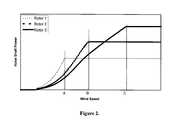
- FIG. 2illustrates possible wind turbine power curves, plotting rotor power capture versus wind speed, for three different rotor diameters, with rotor 1 representing the largest diameter and rotor 3 the smallest diameter
- FIG. 3illustrates the power curve followed by an extendable rotor blade system when controlled in accordance the present invention
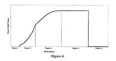
- FIG. 4illustrates the five turbine operating regions of the present invention
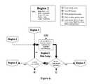
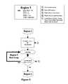
- FIG. 5illustrates a simplified control process loop for system operation within Region 1;
- FIG. 6illustrates a simplified control process loop for system operation within Region 2
- FIG. 7illustrates a simplified control process loop for system operation within Region 3
- FIG. 8illustrates a simplified control process loop for system operation within Region 4.
- FIG. 9illustrates a simplified control process loop for system operation within Region 5.
- the extendable rotor discussed in this inventionmay consist of a number of general configurations.
- an airfoil with a span less than the outer radius of the turbine rotor(see FIGS. 1 a - 1 c ) is controllably maneuvered outwards and inwards from the center of rotation along a load-bearing shaft, increasing and reducing the area swept by the airfoil during rotor revolution.
- the rotorconsists of two main pieces (see FIGS. 1 d - 1 e ): the main blade, and the blade extension (shown by broken lines).
- FIGS. 1 d - 1 ethe main blade
- the blade extensionshown by broken lines
- An aspect of this inventionis a method of controllably limiting the mechanical loads, such as torque, thrust, blade lead-lag (in-plane), blade flap (out of plane), or tower top bending loads, delivered by the rotor to below a threshold value. Achieving this goal enables a single extended rotor blade configuration to operate within adjustable load limits. This enables adaptation to a multitude of wind turbine powertrain manufacturers' designs and to a variety of environmental conditions through use of different control set points, and similarly enables retrofit of existing installed wind turbines.
- mechanical loadssuch as torque, thrust, blade lead-lag (in-plane), blade flap (out of plane), or tower top bending loads
- C pis the power capture efficiency of a given rotor geometry at the specified rotor angular velocity and wind speed. This means that as wind speed increases, the rotor radius must decrease nearly as the inverse of this increase (C p may vary slightly as this occurs) in order to stay within torque limitations.
- ⁇ pis the approximate powertrain efficiency at a given observed output power, P.
- FIG. 2illustrates possible wind turbine power curves, plotting rotor power capture versus wind speed, for three different rotor diameters, with rotor 1 representing the largest diameter and rotor 3 the smallest diameter.
- rotor 1representing the largest diameter
- rotor 3the smallest diameter.
- increasing the rotor diameter at low wind speedsresults in greater power capture at those speeds.
- smaller diameter rotorscan produce more power while staying under the torque constraint for the reason that they are able to rotate faster while remaining under tip speed constraints.
- Points A, B, and Crepresent the wind speeds at which rotors 1, 2, and 3 first produce the single value of torque (or thrust, power, tip speed, blade or tower top bending, or some other limiting load) which limits the turbine capability. Therefore, one goal of this invention is to reduce and extend the radius of the rotor within the wind range bounded by points A and C, as shown in FIG. 3 . At wind speeds greater than point C, the turbine relies on rotor blade feathering or on use of stall-regulated rotor blades to remain in operation at loads below the rated constraints.
- the present inventioncomprises a method of controlling a variable diameter rotor used in power generation equipment driven by slow moving fluids such as wind and water.
- the inventionallows the rotor to yield significant increases in power capture through increase of its swept area, without any penalty in rotor torque or thrust loads delivered to the powertrain or the connected structures. This method is applicable to rotors either having blades that feather or having stall regulated airfoils.
- Region 1spans low velocities below turbine cut-in;
- Region 2spans transition velocities during which the rotor diameter is maximum, rotor speed may vary, and power increases steadily with increasing wind speed;
- Region 3spans higher velocities during which the rotor radius and speed are varied to limit loads while power production continues to increase;
- Region 4spans very high velocities, at which the turbine produces approximately constant power and torque, using temporal rotor speed increases and blade pitch modulation;
- Region 5spans extreme velocities during which the turbine cuts out, feathering its rotor blades to halt rotation and reduce loads.
- rotor 2for an extendable rotor system whose diameter may vary between the extended diameter of rotor 1 and the retracted diameter of rotor 3.
- rotor 2may represent the 50 m diameter rotor common to a 750 kW wind turbine, while rotor 1 and 3 may describe a rotor at the limits of blade extension and retraction such as 65 m fully extended and 35 m fully retracted, while operating under the same loads constraints present in rotor 2.
- FIGS. 5, 6 , 7 , 8 , and 9are illustrated in FIGS. 5, 6 , 7 , 8 , and 9 , respectively.
- the generator(s)are typically shut down, providing no reactive resistance to rotor rotation.
- the rotor bladesare controlled to be at their optimal pitch for power capture in low winds, and the rotor extension is left at maximum radius.
- the generatorengages and the turbine transitions into Region 2.
- FIG. 6shows that while in Region 2, the turbine monitors wind speed, rotor speed, and an assortment of load through sensors. As the wind speed (and the associated rotor power capture) varies, the control system varies the rotor speed to optimize power capture while staying below tip speed limits. If the wind speed and RPM fall below cut-in values, the turbine returns to Region 1 operation. If the any of the sensors exceed limits, the turbine transitions to Region 3 operation.
- the velocity at which the limiting tip speed is reachedmay be less than the velocity where the limiting load (e.g., torque, thrust, blade or tower top bending) is reached. In this case, there is a small velocity range in which the rotors are fully extended and in which the rotational speed does not increase. Alternatively, in some instances such as offshore wind installations where blade acoustics are not as significant, the tip speeds may be allowed to increase, maintaining more optimal power capture efficiency over this range. Because the rotational speed and power capture change, the wind speed at which rated torque is reached may be slightly higher or lower in these instances.
- the limiting loade.g., torque, thrust, blade or tower top bending
- the loadis identical to that produced by the nominal fixed diameter (or semi-retracted) rotor 2 at velocity B and that produced by fully retracted rotor 3 at velocity C.
- the rotor extensionsare gradually retracted, holding fixed the limiting load delivered by the rotor.
- the diameter of the rotoris determined as given in Equations 5 and 6 or 8, and the power curve approximately follows the path shown in FIG. 3 .
- the rotor RPMincreases while maintaining rotor blade tip speeds below the limit. Because the extendable rotor system shown can reduce its diameter below that of the baseline fixed diameter blade of rotor 2, it can rotate at higher speeds. Because it can rotate at higher speeds, it has a higher peak power output while maintaining loads (especially torque) within preset constraints.
- operating Region 3is entered from Region 2 because a load limit is violated or is about to be violated.
- the control systemfirst checks the rotor position (via a sensor) to ensure that the rotor is not fully retracted. If the rotor is fully retracted, the turbine transitions to Region 4 operation. If it is not, the blade extension is incrementally retracted and the RPM and blade pitch are adjusted to optimize power productivity while monitoring rotor speed, blade pitch, extension position, and critical loads.
- the turbine controllerchecks load sensors, and can either repeat these steps or enter Region 3's main run loop, which holds systems static so long as the loads limits are not exceeded through either an upper or lower limit. If loads are too high, the controller re-examines and executes blade retraction.
- schedules or control instructions dictating how the rotor is retracted as a function of wind speedmay be varied for the same rotor blade system, allowing different peak torque and power load criteria to be used.
- the same extendable rotor blade systemmay be installed on a variety of different onshore or offshore wind turbine or ocean current turbine designs, each of which has its own engineering design constraints.
- the gustswill subside in a short period of time, and the power spike can be slowly captured by the turbine as it returns the rotor to the desired slower speed.
- the controlleralways seeks to hold rotor speed constant, but delays implicit in the controller and in the pitch actuator system allow the small speed variability around the desired value.
- Region 4is entered from Region 3 because loads limits are being exceeded and no further blade retraction is possible. While monitoring rotor speed and loads, the rotor speed increases, or flywheels, to absorb gust loads. If the wind is not sustained, the turbine enters its main Region 4 run loop, maintaining torque and power between upper and lower limits. However, if the loads persist beyond a certain time limit, rotor blades are feathered incrementally to off-load power, and the turbine enters the Region 4 run loop. If wind speeds sensors indicate that velocities are extreme, the turbine transitions into operating Region 5, cut-out, by continuing to feather its blades.
- the turbineassesses whether power and torque dip below rated, and if so, it attempts to de-feather the rotor blades to increase rotor power capture efficiency. If the rotor blades are optimally pitched and the power and torque are still too low, the turbine returns to operating Region 3.
- the rotor bladesWhen the velocities exceed a set extreme condition, the rotor blades completely feather or a brake is applied, stopping rotation and power production altogether in order to protect equipment from extreme load conditions that may occur in these velocities.
- FIG. 9illustrates that upon entry into Region 5, the rotor feathers its blades to halt rotation. Once the wind speed falls below a threshold value, the turbine returns to operation in Region 4.
- variable blade pitchBy combining these three parameters, an array of loads and power provided to the turbine can be limited. For example, for short time cycle changes ( ⁇ 1-2 sec), it may be preferable to control blade rotational rate (and thereby power and torque) using power electronics. This does not generally eliminate the load increase, but rather levels out load spikes, reducing the impact of gust or surge variation. For larger time cycles, or velocity changes measured over seconds to tens of seconds or longer, the blade retraction method may be preferable. As a third parameter which may also act on this slower time scale, rotor blade pitch allows power shedding at velocities that result in above-rated power production.
- the blade retraction schedulemay be modified due to control and flow requirements.
- the blade extensionsmay be retracted before the rated load is reached.
- the bladesmay reach full retraction before full power is reached.
- the blade extensionsmay remain partially deployed beyond the velocity at which peak power is reached, instead combining variable pitch with the blade extension for power management.
- controls hysteresismay be implemented, as a part of which, for example, the rotor radius may follow one schedule during increasing velocities, and another in decreasing velocities.
- Hysteresisallows the rotor to operate for longer periods of time at a given set of turbine state parameters (e.g. rotor diameter, blade pitch, and rotor speed) between system actuation, generally reducing the number of actuator cycles and prolonging turbine life.
- This control processmay be improved by adding state control, in which the controller is coded with an assortment of state-space equations governing the operation of turbine systems, including but not limited to blade extensions, rotor blade pitch, and rotor rpm including variable speed control for total or partial conversion for any electrical generator.
- state-space controlis well known in the art [1,2]
- no discussionis found in the art of implementing state-space control of integrated turbine systems incorporating extendable rotor blades.
- This control strategyis based on continual assessment of the state of the turbine. In other words, constant (or periodic) quantification of a number of turbine state variables allows calculation of system responses, dynamically updating system behavior to operate within a specified control boundary.
- This control boundarymay include definition of appropriate system hysteresis. This strategy may allow for broader combinations of individual control states, offering opportunity for increased control stability and for performance optimization.
- state variablessuch as power, torque, thrust, bending, and rpm
- the turbinemay more accurately determine controls actuator commands, optimizing turbine performance.
- sensorsmay include devices such as optical shaft encoders, strain gauges on blades, towers or other structures, generator current and voltage sensors, accelerometers, thermometers, and shaft torque transducers.
- adaptive controlmay be implemented to operate within the loads constraints, using a set of empirical equations with gains that are periodically updated.
- This systemuses a set of operating curves or matrices to determine what combinations of component states are acceptable and to control the system actuators to remain within these state combinations. As system states change, the responses implicit in these matrices are continuously examined and adapted to optimize operation towards specified goals.
- the systemsmay use a similar set of sensors to determine system state (e.g. rotor radius, blade pitch, rotor speed, torque, thrust, bending or wind speed), and control hysteresis may be implicit in that control gains may be altered differently as states vary in the positive and negative directions.
- Look-up tables detailing combined system statese.g. blade pitch, rotor diameter and rotor speed
- independent state variablese.g. wind speed
- measured or calculated state variablese.g. torque, thrust, bending, etc.
- these tablesare designed to optimize a specific area of turbine performance.
- this method of controlhas been widely applied to turbines in the past, it has never been applied to a system incorporating extendable rotor blades, and therefore has not been applied with the goals of maximizing power production while limiting produced loads.
- it is possible to incorporate control hysteresis in these look up tablesby providing different sets of state tables for positive and negative derivatives of independent state variables and by providing a method of transitioning between the tables as these derivatives pass through zero.
- Proportional Integral Derivative controlrelies upon equations that combine terms for proportional response (the difference between a system state and a desired state multiplied by some gain), for integration of past system states, and for system rates of change. Independent states (wind speed, etc.) and measured or calculated states (torque, thrust, bending, etc.) may serve as the inputs for this control method. The methods by which these three terms are calculated may allow for control hysteresis. While PID is widely used in turbines, PID control of turbine systems containing extendable rotor blades, variable rotor speed, and variable rotor pitch is novel.
- Control methodsmay be used to implement this process. These methods generally offer the opportunity to integrate control hysteresis that will allow for reduced actuator cycling in the turbines. These methods may include hybrid control, which may include control methods such as PID equations integrated into a larger set of state-space control equations.
- control strategyenables several physical modifications to past extendable and non-extendable rotor designs. Principally, because the control behavior of this invention allows the blade to be retracted as a function of measured power at a given RPM, having optimal blade performance at in high velocities is not critical. The rotor may simply be retracted more slowly. A small penalty may be paid in this case because this means the rotor will be more extended in higher winds, reducing the rotational rate allowable under tip limitations. This will result in lower permissible power capture to remain within torque or thrust constraints, or increases of these constraints to accommodate the same power capture profile. This affords the opportunity for the rotor extensions to have minimal chord or twist variation or to not be twisted at all, enabling construction with lower-cost methods such as pulltrusion. The power capture efficiency remains high when the rotor is fully extended because the outer half of the rotor blade has minimal twist and chord variation under present designs.
Landscapes
- Engineering & Computer Science (AREA)
- General Engineering & Computer Science (AREA)
- Mechanical Engineering (AREA)
- Sustainable Development (AREA)
- Sustainable Energy (AREA)
- Chemical & Material Sciences (AREA)
- Combustion & Propulsion (AREA)
- Life Sciences & Earth Sciences (AREA)
- Fluid Mechanics (AREA)
- Physics & Mathematics (AREA)
- Power Engineering (AREA)
- Wind Motors (AREA)
- Hydraulic Turbines (AREA)
- Medicines Containing Plant Substances (AREA)
- Control Of Water Turbines (AREA)
- Grinding-Machine Dressing And Accessory Apparatuses (AREA)
- Harvester Elements (AREA)
Abstract
Description


Claims (24)
Priority Applications (11)
| Application Number | Priority Date | Filing Date | Title |
|---|---|---|---|
| US10/039,825US6726439B2 (en) | 2001-08-22 | 2001-10-25 | Retractable rotor blades for power generating wind and ocean current turbines and means for operating below set rotor torque limits |
| ES02776321TES2282475T3 (en) | 2001-10-25 | 2002-10-24 | ROTOR WITH EXTENSIBLE BLADES AND ASSOCIATED CONTROL CRITERIA. |
| DE60218328TDE60218328T2 (en) | 2001-10-25 | 2002-10-24 | ROTOR WITH TELESCOPIC LEAVES AND CONTROL CRITERIA |
| EP02776321AEP1442216B2 (en) | 2001-10-25 | 2002-10-24 | Rotor with extendable blades and control criteria therefor |
| MXPA04003945AMXPA04003945A (en) | 2001-10-25 | 2002-10-24 | Rotor with extendable blades and control criteria therefor. |
| BR0213558-2ABR0213558A (en) | 2001-10-25 | 2002-10-24 | Rotor and control method |
| CA2465271ACA2465271C (en) | 2001-10-25 | 2002-10-24 | Rotor with extendable blades and control criteria therefor |
| PT02776321TPT1442216E (en) | 2001-10-25 | 2002-10-24 | Rotor with extendable blades and control criteria therefor |
| AT02776321TATE354728T1 (en) | 2001-10-25 | 2002-10-24 | ROTOR WITH TELESCOPIC SCROLLING AND CONTROL CRITERIA |
| PCT/US2002/034378WO2003036082A1 (en) | 2001-10-25 | 2002-10-24 | Rotor with extendable blades and control criteria therefor |
| DK02776321TDK1442216T3 (en) | 2001-10-25 | 2002-10-24 | Rotor with extendable blade and control criteria therefore |
Applications Claiming Priority (2)
| Application Number | Priority Date | Filing Date | Title |
|---|---|---|---|
| US31372501P | 2001-08-22 | 2001-08-22 | |
| US10/039,825US6726439B2 (en) | 2001-08-22 | 2001-10-25 | Retractable rotor blades for power generating wind and ocean current turbines and means for operating below set rotor torque limits |
Publications (2)
| Publication Number | Publication Date |
|---|---|
| US20030044274A1 US20030044274A1 (en) | 2003-03-06 |
| US6726439B2true US6726439B2 (en) | 2004-04-27 |
Family
ID=21907529
Family Applications (1)
| Application Number | Title | Priority Date | Filing Date |
|---|---|---|---|
| US10/039,825Expired - Fee RelatedUS6726439B2 (en) | 2001-08-22 | 2001-10-25 | Retractable rotor blades for power generating wind and ocean current turbines and means for operating below set rotor torque limits |
Country Status (11)
| Country | Link |
|---|---|
| US (1) | US6726439B2 (en) |
| EP (1) | EP1442216B2 (en) |
| AT (1) | ATE354728T1 (en) |
| BR (1) | BR0213558A (en) |
| CA (1) | CA2465271C (en) |
| DE (1) | DE60218328T2 (en) |
| DK (1) | DK1442216T3 (en) |
| ES (1) | ES2282475T3 (en) |
| MX (1) | MXPA04003945A (en) |
| PT (1) | PT1442216E (en) |
| WO (1) | WO2003036082A1 (en) |
Cited By (64)
| Publication number | Priority date | Publication date | Assignee | Title |
|---|---|---|---|---|
| US20030075929A1 (en)* | 2001-08-22 | 2003-04-24 | Roland Weitkamp | Wind power plant |
| US20030223868A1 (en)* | 2002-06-04 | 2003-12-04 | Dawson Mark H. | Telescoping wind turbine blade |
| US20030230898A1 (en)* | 2002-05-28 | 2003-12-18 | Jamieson Peter Mckeich | Variable diameter rotor |
| US20040108732A1 (en)* | 2002-05-02 | 2004-06-10 | Roland Weitkamp | Wind power plant, control arrangement for a wind power plant, and method for operating a wind power plant |
| US20050008488A1 (en)* | 2002-01-18 | 2005-01-13 | Brueckner Manfred Karl | Sky turbine that may be mounted on top of a city |
| US20050036888A1 (en)* | 2003-08-12 | 2005-02-17 | Kunio Miyazaki | Windmill structure for use in wind power apparatus |
| US20050200134A1 (en)* | 2002-01-10 | 2005-09-15 | Mitsubishi Heavy Industries, Ltd. | Wind turbine provided with a controller for adjusting active annular plane area and the operating method thereof |
| US20060033338A1 (en)* | 2004-05-11 | 2006-02-16 | Wilson Kitchener C | Wind flow estimation and tracking using tower dynamics |
| US20060045743A1 (en)* | 2004-08-31 | 2006-03-02 | Bertolotti Fabio P | Foldable blades for wind turbines |
| US20060093483A1 (en)* | 2002-01-18 | 2006-05-04 | Brueckner Manfred K | Sky turbine that is mounted on a city |
| US20060103137A1 (en)* | 2000-08-14 | 2006-05-18 | Aloys Wobben | Wind power installation |
| WO2007010322A1 (en) | 2005-07-18 | 2007-01-25 | Clipper Windpower Technology, Inc. | Wind flow estimation and tracking using tower dynamics |
| US20070018457A1 (en)* | 2005-07-22 | 2007-01-25 | Gamesa Eolica, S.A. | Method of operating a wind turbine |
| US20070241567A1 (en)* | 2005-04-14 | 2007-10-18 | Natural Forces, Llc | Reduced Friction Wind Turbine Apparatus and Method |
| WO2008012615A2 (en) | 2006-07-21 | 2008-01-31 | Clipper Windpower Technology, Inc. | Retractable rotor blade structure |
| US20080101916A1 (en)* | 2006-10-20 | 2008-05-01 | David Calley | Method and system for deriving wind speed in a stall controlled wind turbine |
| US20080101930A1 (en)* | 2002-09-23 | 2008-05-01 | Bosche John V | Wind turbine blade deflection control system |
| USD570775S1 (en)* | 2005-11-11 | 2008-06-10 | Mekaro Akita Co., Ltd. | Windmill vane for wind powered generator |
| USD570776S1 (en)* | 2005-11-11 | 2008-06-10 | Mekaro Akita Co., Ltd. | Windmill vane for wind powered generator |
| USD570774S1 (en)* | 2005-11-11 | 2008-06-10 | Mekaro Akita Co., Ltd. | Windmill vane for wind powered generator |
| WO2008081232A1 (en) | 2006-12-28 | 2008-07-10 | Clipper Windpower Technology, Inc. | Wind turbine damping of tower resonant motion and symmetric blade motion using estimation methods |
| USD584685S1 (en)* | 2005-11-11 | 2009-01-13 | Mekaro Akita Co., Ltd. | Windmill vane for wind powered generator |
| USD585020S1 (en)* | 2005-11-11 | 2009-01-20 | Mekaro Akita Co., Ltd. | Windmill vane for wind powered generator |
| US20090021021A1 (en)* | 2007-07-17 | 2009-01-22 | Baseload Energy, Inc. | Power generation system including multiple motors/generators |
| USD591234S1 (en)* | 2008-02-19 | 2009-04-28 | Seabell International Co. Ltd. | Windmill |
| US20090159477A1 (en)* | 2007-12-20 | 2009-06-25 | General Electric Company | Wind turbine blade stowage |
| US20090169357A1 (en)* | 2007-12-31 | 2009-07-02 | General Electric Company | Methods and apparatus for error reduction in rotor loading measurments |
| WO2009090537A2 (en) | 2008-01-14 | 2009-07-23 | Clipper Windpower Technology, Inc. | A modular rotor blade for a power-generating turbine and a method for assembling a power-generating turbine with modular rotor blades |
| WO2009095758A2 (en) | 2008-01-30 | 2009-08-06 | Clipper Windpower Technology, Inc. | Retractable blade structure with a split trailing edge |
| US7581926B1 (en)* | 2004-03-22 | 2009-09-01 | Clipper Windpower Technology, Inc. | Servo-controlled extender mechanism for extendable rotor blades for power generating wind and ocean current turbines |
| US7582977B1 (en)* | 2005-02-25 | 2009-09-01 | Clipper Windpower Technology, Inc. | Extendable rotor blades for power generating wind and ocean current turbines within a module mounted atop a main blade |
| US20090261588A1 (en)* | 2008-04-22 | 2009-10-22 | Repower Systems Ag | Method and system for operating a wind energy installation |
| US7633178B1 (en)* | 2008-11-28 | 2009-12-15 | Wayne Embree | Fluid driven energy generator |
| US20100013236A1 (en)* | 2008-07-18 | 2010-01-21 | Baseload Energy,Inc. | Tether handling for airborne electricity generators |
| US20100038915A1 (en)* | 2007-06-29 | 2010-02-18 | Nobuhiro Murakami | Magnus type wind power generator |
| US20100133823A1 (en)* | 2009-09-25 | 2010-06-03 | General Electric Company | Hybrid braking system and method |
| US20100140949A1 (en)* | 2008-08-22 | 2010-06-10 | Natural Power Concepts, Inc. | Mobile wind turbine |
| US20100143131A1 (en)* | 2008-08-22 | 2010-06-10 | Natural Power Concepts, Inc. | Folding blade turbine |
| US20100158687A1 (en)* | 2008-12-19 | 2010-06-24 | Frontier Wind, Llc | Control Modes for Extendable Rotor Blades |
| US20100196159A1 (en)* | 2009-02-04 | 2010-08-05 | Frontier Wind, Llc | Mass-Centralizing Blade Extension Drive Mount Locations for a Wind Turbine |
| US7775760B1 (en) | 2009-07-02 | 2010-08-17 | Finnell Alfred W | Turbine wheel |
| US20110012363A1 (en)* | 2009-07-02 | 2011-01-20 | Alfred Finnell | Turbine wheel |
| US20110025061A1 (en)* | 2008-04-14 | 2011-02-03 | Wongalea Holdings Oty Ltd | Control system for a windmill kite |
| US20110033293A1 (en)* | 2009-08-10 | 2011-02-10 | Lincoln Joseph Cavalieri | Retractable Wind Turbine |
| WO2011046632A1 (en)* | 2009-10-15 | 2011-04-21 | Smith Danny J | Wind power generation system |
| US20120093627A1 (en)* | 2010-10-18 | 2012-04-19 | Clipper Windpower, Inc. | Method for site specific energy capture optimization through modular rotor blade tip extension |
| US8253268B1 (en) | 2009-10-15 | 2012-08-28 | Airgenesis, LLC | Wind power generation system |
| US8362631B2 (en) | 2006-07-10 | 2013-01-29 | Roe Justin C | Marine energy hybrid |
| US20130028733A1 (en)* | 2010-10-08 | 2013-01-31 | Mccune Earl | Wind turbine having flow-aligned blades |
| US8508065B1 (en) | 2010-11-24 | 2013-08-13 | Chu B. Lee | Windmill generator system |
| US8710694B2 (en) | 2012-04-06 | 2014-04-29 | Airgenesis, LLC | RPM Controlled Wind Power Generation System |
| US20150016996A1 (en)* | 2011-12-29 | 2015-01-15 | Rolf Rohden | Telescopic rotor blade and telescopic tower, wind turbine, and wind farm |
| US9074577B2 (en) | 2013-03-15 | 2015-07-07 | Dehlsen Associates, Llc | Wave energy converter system |
| US9371819B2 (en) | 2012-07-09 | 2016-06-21 | Envision Energy (Denmark) Aps | Method and system to actively pitch to reduce extreme loads on wind turbine |
| US9500179B2 (en) | 2010-05-24 | 2016-11-22 | Vestas Wind Systems A/S | Segmented wind turbine blades with truss connection regions, and associated systems and methods |
| US9500180B1 (en) | 2012-07-29 | 2016-11-22 | Gregg Chandler | Retractable energy generating wind fan with self-adjusting blades |
| US9617979B2 (en) | 2013-10-30 | 2017-04-11 | Airgenesis, LLC | Motor assisted power generation system |
| US20170130698A1 (en)* | 2014-06-18 | 2017-05-11 | Wobben Properties Gmbh | Wind turbine rotor blade, wind turbine and method for operating a wind turbine |
| US9796466B2 (en) | 2013-02-25 | 2017-10-24 | Airgenesis, LLC | Variable coupler drive |
| US9874088B2 (en) | 2014-08-15 | 2018-01-23 | Baker Hughes, A Ge Company, Llc | Wellbore flowmeter |
| US10435145B1 (en) | 2009-07-02 | 2019-10-08 | Alfred Finnell | Vehicle with tension wing assembly |
| US10550823B2 (en) | 2016-08-10 | 2020-02-04 | General Electric Company | Method for balancing segmented wind turbine rotor blades |
| US11021243B1 (en) | 2009-07-02 | 2021-06-01 | Alfred Finnell | Tension airfoil assembly and implementation for power generation and aviation |
| US11885293B2 (en) | 2021-04-12 | 2024-01-30 | Lm Wind Power A/S | Extendable wind turbine blade |
Families Citing this family (25)
| Publication number | Priority date | Publication date | Assignee | Title |
|---|---|---|---|---|
| US6952058B2 (en)* | 2003-02-20 | 2005-10-04 | Wecs, Inc. | Wind energy conversion system |
| WO2005017351A1 (en)* | 2003-07-29 | 2005-02-24 | General Electric Company | Variable diameter rotor |
| CA2557396C (en) | 2004-02-27 | 2010-12-21 | Mitsubishi Heavy Industries, Ltd. | Wind turbine generator, active damping method thereof, and windmill tower |
| ES2216731B1 (en)* | 2004-06-04 | 2006-02-16 | Esdras Automatica, S.L. | POWER CONTROL OF WIND TURBINES THROUGH COEFFICIENT VARIATIONS AND DIMENSION OF SWEEPING BANDS. |
| ES2263389B1 (en)* | 2005-06-03 | 2007-12-01 | Esdras Automaticas, S.L. | STRUCTURE OF SUBALABES FOR REDUCTION OF THE WEIGHT OF LAS PALAS IN EOLIC TURBINES. |
| ES2322423B1 (en) | 2007-06-21 | 2010-01-26 | Manuel Torres Martinez | HORIZONTAL SHAFT AEROGENERATOR SHOVEL. |
| DE102007062616A1 (en)* | 2007-12-22 | 2009-06-25 | Arno Helper | Wind power generator for producing electricity from mechanical energy, has wind wheel with rotor having rotor blades coupled to rotor shaft, where length of rotor blades is adjustable, and tower is lengthwise adjustable |
| ES2335640A1 (en)* | 2009-01-27 | 2010-03-30 | Universidad Politecnica De Madrid | Wind turbine blade |
| ES2382631B1 (en)* | 2009-09-03 | 2013-05-03 | Gamesa Innovation & Technology, S.L. | METHODS AND SYSTEMS OF AIRCRAFT CONTROL |
| GB0921207D0 (en)* | 2009-12-03 | 2010-01-20 | Tidal Energy Ltd | Tidal turbine system |
| DE102012201469A1 (en)* | 2012-02-01 | 2013-08-01 | Aktiebolaget Skf | Wind or tidal flow power plant, has wings comprising wing sections that are moved to extended condition for enlarging wing area or to retracted condition for reducing area, where sections are movable in radial direction relative to wings |
| US9297357B2 (en) | 2013-04-04 | 2016-03-29 | General Electric Company | Blade insert for a wind turbine rotor blade |
| US9506452B2 (en) | 2013-08-28 | 2016-11-29 | General Electric Company | Method for installing a shear web insert within a segmented rotor blade assembly |
| US10054108B2 (en)* | 2014-10-10 | 2018-08-21 | General Electric Company | Wind turbine system and method for controlling a wind turbine system by power monitoring |
| US10738764B2 (en) | 2016-04-18 | 2020-08-11 | Star Wind Turbines Llc | High torque, low RPM horizontal axis wind turbine |
| US20180003154A1 (en)* | 2016-06-30 | 2018-01-04 | General Electric Company | Methods and systems for feedforward control of wind turbines |
| CN106121923A (en)* | 2016-07-26 | 2016-11-16 | 天津大学 | A kind of vertical pivot is utilized to carry out marine marine tidal-current energy and the dual-purpose TRT of wind energy |
| DE102018100129A1 (en)* | 2018-01-04 | 2019-07-04 | Wobben Properties Gmbh | Method for controlling a wind energy plant and wind energy plant |
| CN112534132B (en)* | 2018-08-01 | 2023-08-25 | 维斯塔斯风力系统有限公司 | Noise reduction in wind turbines with hinged blades |
| DE102018009333A1 (en)* | 2018-11-28 | 2020-05-28 | Senvion Gmbh | Method for operating a wind turbine |
| FR3092562B1 (en)* | 2019-02-12 | 2022-01-28 | Airbus Helicopters | Process for optimizing the noise generated on the ground by a rotorcraft |
| CN111734585B (en)* | 2020-06-18 | 2023-06-27 | 上海电气风电集团股份有限公司 | Method and device for determining limit load of wind driven generator and readable storage medium |
| WO2022258520A1 (en) | 2021-06-07 | 2022-12-15 | Aarhus Universitet | Wind turbine with combined pitch and radial displacement coupling and control method |
| CN116123027B (en)* | 2022-12-19 | 2024-08-30 | 中国华能集团清洁能源技术研究院有限公司 | Control method and system of wind turbine generator with multistage retractable blades |
| US12269580B2 (en) | 2023-05-30 | 2025-04-08 | Archer Aviation Inc. | Systems and methods for aircraft load alleviation |
Citations (24)
| Publication number | Priority date | Publication date | Assignee | Title |
|---|---|---|---|---|
| US2108245A (en) | 1936-06-02 | 1938-02-15 | Jr Thomas Ash | Gyratory airplane wing |
| US2163482A (en) | 1936-01-01 | 1939-06-20 | Cameron Peter | Aircraft having rotative sustaining means |
| US2979288A (en) | 1959-01-15 | 1961-04-11 | Klein Albert | Aircraft propeller arrangement and means for elongating same |
| US3249160A (en) | 1964-06-10 | 1966-05-03 | Messerschmitt Ag | Rotor blade construction for aircraft |
| US3606571A (en) | 1968-03-08 | 1971-09-20 | Reginald T Wood | Stowed rotor |
| US3814351A (en) | 1972-12-06 | 1974-06-04 | United Aircraft Corp | Coaxial rotor yaw control |
| US4074952A (en) | 1976-06-28 | 1978-02-21 | United Technologies Corporation | Locking control and overtravel safety stop system for variable length rotor blades |
| US4080097A (en) | 1976-06-28 | 1978-03-21 | United Technologies Corporation | Locking control and overtravel safety stop system for variable length rotor blades |
| US4139330A (en) | 1977-04-14 | 1979-02-13 | Buffalo Forge Company | Adjustable vane centrifugal pump impeller construction |
| US4180372A (en) | 1977-03-02 | 1979-12-25 | Grumman Corporation | Wind rotor automatic air brake |
| US4710101A (en) | 1985-04-26 | 1987-12-01 | James Howden & Company Limited | Wind turbine |
| US5253979A (en) | 1992-06-01 | 1993-10-19 | United Technologies Corporation | Variable diameter rotor having an offset twist |
| US5299912A (en) | 1992-07-28 | 1994-04-05 | United Technologies Corporation | Drive system for changing the diameter of a variable diameter rotor |
| US5310314A (en) | 1993-03-26 | 1994-05-10 | Gyrodyne Company Of America, Inc. | Directional control system for rotary wing aircraft |
| US5620303A (en) | 1995-12-11 | 1997-04-15 | Sikorsky Aircraft Corporation | Rotor system having alternating length rotor blades for reducing blade-vortex interaction (BVI) noise |
| US5620304A (en) | 1995-12-11 | 1997-04-15 | Sikorsky Aircraft Corporation | Rotor system having alternating length rotor blades and positioning means therefor for reducing blade-vortex interaction (BVI) noise |
| US5630705A (en) | 1992-04-29 | 1997-05-20 | Eikelenboom; Pieter A. J. | Rotor construction for windmill |
| US5636969A (en) | 1995-03-28 | 1997-06-10 | Sikorsky Aircraft Corporation | Torque tube/spar assembly for variable diameter helicopter rotors |
| US5642982A (en) | 1995-12-11 | 1997-07-01 | Sikorsky Aircraft Corporation | Retraction/extension mechanism for variable diameter rotors |
| US5655879A (en) | 1995-03-28 | 1997-08-12 | Sikorsky Aircraft Corporation | Mounting arrangement for variable diameter rotor blade assemblies |
| US5735670A (en) | 1995-12-11 | 1998-04-07 | Sikorsky Aircraft Corporation | Rotor system having alternating length rotor blades and positioning means therefor for reducing blade-vortex interaction (BVI) noise |
| US6019578A (en) | 1998-12-18 | 2000-02-01 | Sikorsky Aircraft Corporation | Variable diameter rotor blade actuation system |
| US6030177A (en) | 1998-12-18 | 2000-02-29 | Sikorsky Aircraft Corporation | Drive system for a variable diameter tilt rotor |
| US6398497B1 (en) | 2001-02-20 | 2002-06-04 | Sikorsky Aircraft Corporation | Blade lock system for variable diameter rotor systems |
Family Cites Families (11)
| Publication number | Priority date | Publication date | Assignee | Title |
|---|---|---|---|---|
| GB252461A (en)† | 1925-02-27 | 1926-05-27 | Kurt Bilau | Improvements in or relating to wind-driven prime movers |
| FR1516196A (en)* | 1967-01-26 | 1968-03-08 | Improvements to industrial air propellers | |
| JPS5920871B2 (en)* | 1980-08-04 | 1984-05-16 | 工業技術院長 | windmill |
| US5155375A (en)* | 1991-09-19 | 1992-10-13 | U.S. Windpower, Inc. | Speed control system for a variable speed wind turbine |
| DE4428731A1 (en)* | 1994-08-15 | 1996-02-22 | Infan Gmbh Ingenieurgesellscha | Variable length rotor blade for wind power systems |
| FR2751693B1 (en)† | 1996-07-26 | 1998-09-04 | Toulminet Michel | VARIABLE LENGTH BLADE |
| DE29715249U1 (en)* | 1997-08-25 | 1998-12-24 | Institut für Solare Energieversorgungstechnik Verein an der Universität Gesamthochschule Kassel eV, 34119 Kassel | Wind turbine |
| US6091161A (en)* | 1998-11-03 | 2000-07-18 | Dehlsen Associates, L.L.C. | Method of controlling operating depth of an electricity-generating device having a tethered water current-driven turbine |
| DE69919910T2 (en)* | 1999-11-03 | 2005-09-08 | Vestas Wind Systems A/S | METHOD FOR REGULATING A WIND POWER PLANT AND CORRESPONDING WIND POWER PLANT |
| WO2002077449A1 (en)* | 1999-11-11 | 2002-10-03 | Hitachi Zosen Corporation | Propeller type windmill for power generation |
| JP2001132615A (en)† | 1999-11-11 | 2001-05-18 | Hitachi Zosen Corp | Propeller type wind turbine for power generation |
- 2001
- 2001-10-25USUS10/039,825patent/US6726439B2/ennot_activeExpired - Fee Related
- 2002
- 2002-10-24DEDE60218328Tpatent/DE60218328T2/ennot_activeExpired - Lifetime
- 2002-10-24CACA2465271Apatent/CA2465271C/ennot_activeExpired - Fee Related
- 2002-10-24EPEP02776321Apatent/EP1442216B2/ennot_activeExpired - Lifetime
- 2002-10-24MXMXPA04003945Apatent/MXPA04003945A/enactiveIP Right Grant
- 2002-10-24ATAT02776321Tpatent/ATE354728T1/ennot_activeIP Right Cessation
- 2002-10-24PTPT02776321Tpatent/PT1442216E/enunknown
- 2002-10-24WOPCT/US2002/034378patent/WO2003036082A1/ennot_activeCeased
- 2002-10-24ESES02776321Tpatent/ES2282475T3/ennot_activeExpired - Lifetime
- 2002-10-24BRBR0213558-2Apatent/BR0213558A/ennot_activeApplication Discontinuation
- 2002-10-24DKDK02776321Tpatent/DK1442216T3/enactive
Patent Citations (24)
| Publication number | Priority date | Publication date | Assignee | Title |
|---|---|---|---|---|
| US2163482A (en) | 1936-01-01 | 1939-06-20 | Cameron Peter | Aircraft having rotative sustaining means |
| US2108245A (en) | 1936-06-02 | 1938-02-15 | Jr Thomas Ash | Gyratory airplane wing |
| US2979288A (en) | 1959-01-15 | 1961-04-11 | Klein Albert | Aircraft propeller arrangement and means for elongating same |
| US3249160A (en) | 1964-06-10 | 1966-05-03 | Messerschmitt Ag | Rotor blade construction for aircraft |
| US3606571A (en) | 1968-03-08 | 1971-09-20 | Reginald T Wood | Stowed rotor |
| US3814351A (en) | 1972-12-06 | 1974-06-04 | United Aircraft Corp | Coaxial rotor yaw control |
| US4074952A (en) | 1976-06-28 | 1978-02-21 | United Technologies Corporation | Locking control and overtravel safety stop system for variable length rotor blades |
| US4080097A (en) | 1976-06-28 | 1978-03-21 | United Technologies Corporation | Locking control and overtravel safety stop system for variable length rotor blades |
| US4180372A (en) | 1977-03-02 | 1979-12-25 | Grumman Corporation | Wind rotor automatic air brake |
| US4139330A (en) | 1977-04-14 | 1979-02-13 | Buffalo Forge Company | Adjustable vane centrifugal pump impeller construction |
| US4710101A (en) | 1985-04-26 | 1987-12-01 | James Howden & Company Limited | Wind turbine |
| US5630705A (en) | 1992-04-29 | 1997-05-20 | Eikelenboom; Pieter A. J. | Rotor construction for windmill |
| US5253979A (en) | 1992-06-01 | 1993-10-19 | United Technologies Corporation | Variable diameter rotor having an offset twist |
| US5299912A (en) | 1992-07-28 | 1994-04-05 | United Technologies Corporation | Drive system for changing the diameter of a variable diameter rotor |
| US5310314A (en) | 1993-03-26 | 1994-05-10 | Gyrodyne Company Of America, Inc. | Directional control system for rotary wing aircraft |
| US5636969A (en) | 1995-03-28 | 1997-06-10 | Sikorsky Aircraft Corporation | Torque tube/spar assembly for variable diameter helicopter rotors |
| US5655879A (en) | 1995-03-28 | 1997-08-12 | Sikorsky Aircraft Corporation | Mounting arrangement for variable diameter rotor blade assemblies |
| US5620303A (en) | 1995-12-11 | 1997-04-15 | Sikorsky Aircraft Corporation | Rotor system having alternating length rotor blades for reducing blade-vortex interaction (BVI) noise |
| US5620304A (en) | 1995-12-11 | 1997-04-15 | Sikorsky Aircraft Corporation | Rotor system having alternating length rotor blades and positioning means therefor for reducing blade-vortex interaction (BVI) noise |
| US5642982A (en) | 1995-12-11 | 1997-07-01 | Sikorsky Aircraft Corporation | Retraction/extension mechanism for variable diameter rotors |
| US5735670A (en) | 1995-12-11 | 1998-04-07 | Sikorsky Aircraft Corporation | Rotor system having alternating length rotor blades and positioning means therefor for reducing blade-vortex interaction (BVI) noise |
| US6019578A (en) | 1998-12-18 | 2000-02-01 | Sikorsky Aircraft Corporation | Variable diameter rotor blade actuation system |
| US6030177A (en) | 1998-12-18 | 2000-02-29 | Sikorsky Aircraft Corporation | Drive system for a variable diameter tilt rotor |
| US6398497B1 (en) | 2001-02-20 | 2002-06-04 | Sikorsky Aircraft Corporation | Blade lock system for variable diameter rotor systems |
Cited By (109)
| Publication number | Priority date | Publication date | Assignee | Title |
|---|---|---|---|---|
| US7102248B2 (en) | 2000-08-14 | 2006-09-05 | Aloys Wobben | Wind power installation |
| US20060103137A1 (en)* | 2000-08-14 | 2006-05-18 | Aloys Wobben | Wind power installation |
| US6870281B2 (en)* | 2001-08-22 | 2005-03-22 | General Electric Company | Wind power plant stabilization |
| US20030075929A1 (en)* | 2001-08-22 | 2003-04-24 | Roland Weitkamp | Wind power plant |
| US7425774B2 (en)* | 2002-01-10 | 2008-09-16 | Mitsubishi Heavy Industries Ltd. | Wind turbine provided with a controller for adjusting active annular plane area and the operating method thereof |
| US7425775B2 (en) | 2002-01-10 | 2008-09-16 | Mitsubishi Heavy Industries Ltd. | Wind turbine provided with a controller for adjusting active annular plane area and the operating method thereof |
| US20050200134A1 (en)* | 2002-01-10 | 2005-09-15 | Mitsubishi Heavy Industries, Ltd. | Wind turbine provided with a controller for adjusting active annular plane area and the operating method thereof |
| US20050200135A1 (en)* | 2002-01-10 | 2005-09-15 | Mitsubishi Heavy Industries, Ltd. | Wind turbine provided with a controller for adjusting active annular plane area and the operating method thereof |
| US20050207890A1 (en)* | 2002-01-10 | 2005-09-22 | Mitsubishi Heavy Industries, Ltd. | Wind turbine provided with a controller for adjusting active annular plane area and the operating method thereof |
| US20050207889A1 (en)* | 2002-01-10 | 2005-09-22 | Mitsubishi Heavy Industries, Ltd. | Wind turbine provided with a controller for adjusting active annular plane area and the operating method thereof |
| US7436085B2 (en) | 2002-01-10 | 2008-10-14 | Mitsubishi Heavy Industries Ltd. | Wind turbine provided with a controller for adjusting active annular plane area and the operating method thereof |
| US7071578B1 (en)* | 2002-01-10 | 2006-07-04 | Mitsubishi Heavy Industries, Ltd. | Wind turbine provided with a controller for adjusting active annular plane area and the operating method thereof |
| US20060093483A1 (en)* | 2002-01-18 | 2006-05-04 | Brueckner Manfred K | Sky turbine that is mounted on a city |
| US20050008488A1 (en)* | 2002-01-18 | 2005-01-13 | Brueckner Manfred Karl | Sky turbine that may be mounted on top of a city |
| US7131812B2 (en) | 2002-01-18 | 2006-11-07 | Manfred Karl Brueckner | Sky turbine that is mounted on a city |
| US6940186B2 (en)* | 2002-05-02 | 2005-09-06 | General Electric Company | Wind turbine having sensor elements mounted on rotor blades |
| US20040108732A1 (en)* | 2002-05-02 | 2004-06-10 | Roland Weitkamp | Wind power plant, control arrangement for a wind power plant, and method for operating a wind power plant |
| US20030230898A1 (en)* | 2002-05-28 | 2003-12-18 | Jamieson Peter Mckeich | Variable diameter rotor |
| US6972498B2 (en)* | 2002-05-28 | 2005-12-06 | General Electric Company | Variable diameter wind turbine rotor blades |
| US7632070B2 (en) | 2002-06-04 | 2009-12-15 | Dawson Mark H | Telescoping wind turbine blade |
| US20050285406A1 (en)* | 2002-06-04 | 2005-12-29 | Dawson Mark H | Telescoping wind turbine blade |
| US20030223868A1 (en)* | 2002-06-04 | 2003-12-04 | Dawson Mark H. | Telescoping wind turbine blade |
| US6902370B2 (en) | 2002-06-04 | 2005-06-07 | Energy Unlimited, Inc. | Telescoping wind turbine blade |
| US20080101930A1 (en)* | 2002-09-23 | 2008-05-01 | Bosche John V | Wind turbine blade deflection control system |
| US20050036888A1 (en)* | 2003-08-12 | 2005-02-17 | Kunio Miyazaki | Windmill structure for use in wind power apparatus |
| US7581926B1 (en)* | 2004-03-22 | 2009-09-01 | Clipper Windpower Technology, Inc. | Servo-controlled extender mechanism for extendable rotor blades for power generating wind and ocean current turbines |
| US20060033338A1 (en)* | 2004-05-11 | 2006-02-16 | Wilson Kitchener C | Wind flow estimation and tracking using tower dynamics |
| US7317260B2 (en)* | 2004-05-11 | 2008-01-08 | Clipper Windpower Technology, Inc. | Wind flow estimation and tracking using tower dynamics |
| US20060045743A1 (en)* | 2004-08-31 | 2006-03-02 | Bertolotti Fabio P | Foldable blades for wind turbines |
| US8419362B2 (en) | 2004-08-31 | 2013-04-16 | Hamilton Sundstrand Corporation | Foldable blades for wind turbines |
| US7582977B1 (en)* | 2005-02-25 | 2009-09-01 | Clipper Windpower Technology, Inc. | Extendable rotor blades for power generating wind and ocean current turbines within a module mounted atop a main blade |
| US7633177B2 (en) | 2005-04-14 | 2009-12-15 | Natural Forces, Llc | Reduced friction wind turbine apparatus and method |
| US20070241567A1 (en)* | 2005-04-14 | 2007-10-18 | Natural Forces, Llc | Reduced Friction Wind Turbine Apparatus and Method |
| WO2007010322A1 (en) | 2005-07-18 | 2007-01-25 | Clipper Windpower Technology, Inc. | Wind flow estimation and tracking using tower dynamics |
| US20070018457A1 (en)* | 2005-07-22 | 2007-01-25 | Gamesa Eolica, S.A. | Method of operating a wind turbine |
| US7476985B2 (en)* | 2005-07-22 | 2009-01-13 | Gamesa Innovation & Technology, S.L. | Method of operating a wind turbine |
| USD584685S1 (en)* | 2005-11-11 | 2009-01-13 | Mekaro Akita Co., Ltd. | Windmill vane for wind powered generator |
| USD585020S1 (en)* | 2005-11-11 | 2009-01-20 | Mekaro Akita Co., Ltd. | Windmill vane for wind powered generator |
| USD570774S1 (en)* | 2005-11-11 | 2008-06-10 | Mekaro Akita Co., Ltd. | Windmill vane for wind powered generator |
| USD570776S1 (en)* | 2005-11-11 | 2008-06-10 | Mekaro Akita Co., Ltd. | Windmill vane for wind powered generator |
| USD570775S1 (en)* | 2005-11-11 | 2008-06-10 | Mekaro Akita Co., Ltd. | Windmill vane for wind powered generator |
| US8362631B2 (en) | 2006-07-10 | 2013-01-29 | Roe Justin C | Marine energy hybrid |
| US20090304507A1 (en)* | 2006-07-21 | 2009-12-10 | Dehlsen James G P | Retractable rotor blade structure |
| WO2008012615A2 (en) | 2006-07-21 | 2008-01-31 | Clipper Windpower Technology, Inc. | Retractable rotor blade structure |
| US20080101916A1 (en)* | 2006-10-20 | 2008-05-01 | David Calley | Method and system for deriving wind speed in a stall controlled wind turbine |
| WO2008081232A1 (en) | 2006-12-28 | 2008-07-10 | Clipper Windpower Technology, Inc. | Wind turbine damping of tower resonant motion and symmetric blade motion using estimation methods |
| US20100038915A1 (en)* | 2007-06-29 | 2010-02-18 | Nobuhiro Murakami | Magnus type wind power generator |
| US7675189B2 (en) | 2007-07-17 | 2010-03-09 | Baseload Energy, Inc. | Power generation system including multiple motors/generators |
| US20090021021A1 (en)* | 2007-07-17 | 2009-01-22 | Baseload Energy, Inc. | Power generation system including multiple motors/generators |
| US20110031344A1 (en)* | 2007-07-17 | 2011-02-10 | Baseload Energy, Inc. | High voltage flying apparatus employing multiple motors |
| US8444081B2 (en) | 2007-07-17 | 2013-05-21 | Jst, Llc | High voltage flying apparatus employing multiple motors |
| DE102008055544B4 (en) | 2007-12-20 | 2022-07-14 | General Electric Co. | Stowage of wind turbine blades |
| DE102008055544A1 (en) | 2007-12-20 | 2009-06-25 | General Electric Co. | Stowage of wind turbine blades |
| US20090159477A1 (en)* | 2007-12-20 | 2009-06-25 | General Electric Company | Wind turbine blade stowage |
| US8113778B2 (en) | 2007-12-20 | 2012-02-14 | General Electric Company | Wind turbine blade stowage |
| US8215905B2 (en) | 2007-12-31 | 2012-07-10 | General Electric Corporation | Methods and apparatus for error reduction in rotor loading measurements |
| US20090169357A1 (en)* | 2007-12-31 | 2009-07-02 | General Electric Company | Methods and apparatus for error reduction in rotor loading measurments |
| WO2009090537A2 (en) | 2008-01-14 | 2009-07-23 | Clipper Windpower Technology, Inc. | A modular rotor blade for a power-generating turbine and a method for assembling a power-generating turbine with modular rotor blades |
| WO2009095758A2 (en) | 2008-01-30 | 2009-08-06 | Clipper Windpower Technology, Inc. | Retractable blade structure with a split trailing edge |
| USD591234S1 (en)* | 2008-02-19 | 2009-04-28 | Seabell International Co. Ltd. | Windmill |
| US20110025061A1 (en)* | 2008-04-14 | 2011-02-03 | Wongalea Holdings Oty Ltd | Control system for a windmill kite |
| US20090261588A1 (en)* | 2008-04-22 | 2009-10-22 | Repower Systems Ag | Method and system for operating a wind energy installation |
| US8247913B2 (en)* | 2008-04-22 | 2012-08-21 | Repower Systems Ag | Method and system for operating a wind energy installation |
| US8907516B2 (en) | 2008-07-18 | 2014-12-09 | Jst Llc | Tether handling for airborne electricity generators |
| US8350403B2 (en) | 2008-07-18 | 2013-01-08 | Baseload Energy, Inc. | Tether handling for airborne electricity generators |
| US20100013236A1 (en)* | 2008-07-18 | 2010-01-21 | Baseload Energy,Inc. | Tether handling for airborne electricity generators |
| US20100140949A1 (en)* | 2008-08-22 | 2010-06-10 | Natural Power Concepts, Inc. | Mobile wind turbine |
| US8915697B2 (en) | 2008-08-22 | 2014-12-23 | Natural Power Concepts Inc. | Mobile wind turbine |
| US20100143131A1 (en)* | 2008-08-22 | 2010-06-10 | Natural Power Concepts, Inc. | Folding blade turbine |
| US7633178B1 (en)* | 2008-11-28 | 2009-12-15 | Wayne Embree | Fluid driven energy generator |
| US20100158687A1 (en)* | 2008-12-19 | 2010-06-24 | Frontier Wind, Llc | Control Modes for Extendable Rotor Blades |
| US8128361B2 (en)* | 2008-12-19 | 2012-03-06 | Frontier Wind, Llc | Control modes for extendable rotor blades |
| WO2010080391A3 (en)* | 2008-12-19 | 2010-12-02 | Frontier Wind, Llc | Control modes for extendable rotor blades |
| WO2010080391A2 (en) | 2008-12-19 | 2010-07-15 | Frontier Wind, Llc | Control modes for extendable rotor blades |
| US8231347B2 (en) | 2009-02-04 | 2012-07-31 | Frontier Wind, Llc | Mass-centralizing blade extension drive mount locations for wind turbine |
| US20100196159A1 (en)* | 2009-02-04 | 2010-08-05 | Frontier Wind, Llc | Mass-Centralizing Blade Extension Drive Mount Locations for a Wind Turbine |
| US11021243B1 (en) | 2009-07-02 | 2021-06-01 | Alfred Finnell | Tension airfoil assembly and implementation for power generation and aviation |
| US7775760B1 (en) | 2009-07-02 | 2010-08-17 | Finnell Alfred W | Turbine wheel |
| US10435145B1 (en) | 2009-07-02 | 2019-10-08 | Alfred Finnell | Vehicle with tension wing assembly |
| US8668455B2 (en) | 2009-07-02 | 2014-03-11 | Alfred Finnell | Turbine wheel |
| US20110012363A1 (en)* | 2009-07-02 | 2011-01-20 | Alfred Finnell | Turbine wheel |
| US20110033293A1 (en)* | 2009-08-10 | 2011-02-10 | Lincoln Joseph Cavalieri | Retractable Wind Turbine |
| US8080891B2 (en)* | 2009-09-25 | 2011-12-20 | General Electric Company | Hybrid braking system and method |
| US20100133823A1 (en)* | 2009-09-25 | 2010-06-03 | General Electric Company | Hybrid braking system and method |
| US8247918B2 (en) | 2009-10-15 | 2012-08-21 | Airgenesis Llc | Power generation coupler |
| WO2011046632A1 (en)* | 2009-10-15 | 2011-04-21 | Smith Danny J | Wind power generation system |
| US20110223017A1 (en)* | 2009-10-15 | 2011-09-15 | Airgenesis Llc | Wind Power Generation System |
| US8253268B1 (en) | 2009-10-15 | 2012-08-28 | Airgenesis, LLC | Wind power generation system |
| US8178991B2 (en) | 2009-10-15 | 2012-05-15 | Airgenesis Llc | Wind power generation system |
| US8482150B2 (en) | 2009-10-15 | 2013-07-09 | Airgenesis Llc | Method of power generation |
| US9500179B2 (en) | 2010-05-24 | 2016-11-22 | Vestas Wind Systems A/S | Segmented wind turbine blades with truss connection regions, and associated systems and methods |
| US20130028733A1 (en)* | 2010-10-08 | 2013-01-31 | Mccune Earl | Wind turbine having flow-aligned blades |
| US8899921B2 (en)* | 2010-10-08 | 2014-12-02 | Earl McCune | Wind turbine having flow-aligned blades |
| US20150044055A1 (en)* | 2010-10-08 | 2015-02-12 | Earl McCune | Wind turbine having flow-aligned blades |
| US9581132B2 (en)* | 2010-10-08 | 2017-02-28 | Earl McCune | Wind turbine having flow-aligned blades |
| US20120093627A1 (en)* | 2010-10-18 | 2012-04-19 | Clipper Windpower, Inc. | Method for site specific energy capture optimization through modular rotor blade tip extension |
| US8508065B1 (en) | 2010-11-24 | 2013-08-13 | Chu B. Lee | Windmill generator system |
| US20150016996A1 (en)* | 2011-12-29 | 2015-01-15 | Rolf Rohden | Telescopic rotor blade and telescopic tower, wind turbine, and wind farm |
| US8710694B2 (en) | 2012-04-06 | 2014-04-29 | Airgenesis, LLC | RPM Controlled Wind Power Generation System |
| US9371819B2 (en) | 2012-07-09 | 2016-06-21 | Envision Energy (Denmark) Aps | Method and system to actively pitch to reduce extreme loads on wind turbine |
| US9500180B1 (en) | 2012-07-29 | 2016-11-22 | Gregg Chandler | Retractable energy generating wind fan with self-adjusting blades |
| US9796466B2 (en) | 2013-02-25 | 2017-10-24 | Airgenesis, LLC | Variable coupler drive |
| US9074577B2 (en) | 2013-03-15 | 2015-07-07 | Dehlsen Associates, Llc | Wave energy converter system |
| US9617979B2 (en) | 2013-10-30 | 2017-04-11 | Airgenesis, LLC | Motor assisted power generation system |
| US20170130698A1 (en)* | 2014-06-18 | 2017-05-11 | Wobben Properties Gmbh | Wind turbine rotor blade, wind turbine and method for operating a wind turbine |
| US10465656B2 (en)* | 2014-06-18 | 2019-11-05 | Wobben Properties Gmbh | Wind turbine rotor blade, wind turbine and method for operating a wind turbine |
| US9874088B2 (en) | 2014-08-15 | 2018-01-23 | Baker Hughes, A Ge Company, Llc | Wellbore flowmeter |
| US10550823B2 (en) | 2016-08-10 | 2020-02-04 | General Electric Company | Method for balancing segmented wind turbine rotor blades |
| US11885293B2 (en) | 2021-04-12 | 2024-01-30 | Lm Wind Power A/S | Extendable wind turbine blade |
Also Published As
| Publication number | Publication date |
|---|---|
| PT1442216E (en) | 2007-05-31 |
| BR0213558A (en) | 2004-10-26 |
| DK1442216T3 (en) | 2007-06-11 |
| CA2465271A1 (en) | 2003-05-01 |
| ATE354728T1 (en) | 2007-03-15 |
| DE60218328D1 (en) | 2007-04-05 |
| EP1442216A1 (en) | 2004-08-04 |
| WO2003036082A1 (en) | 2003-05-01 |
| ES2282475T3 (en) | 2007-10-16 |
| DE60218328T2 (en) | 2007-08-30 |
| US20030044274A1 (en) | 2003-03-06 |
| CA2465271C (en) | 2011-09-20 |
| EP1442216B1 (en) | 2007-02-21 |
| EP1442216B2 (en) | 2013-03-13 |
| MXPA04003945A (en) | 2004-11-29 |
Similar Documents
| Publication | Publication Date | Title |
|---|---|---|
| US6726439B2 (en) | Retractable rotor blades for power generating wind and ocean current turbines and means for operating below set rotor torque limits | |
| US6441507B1 (en) | Rotor pitch control method and apparatus for parking wind turbine | |
| EP2306003B1 (en) | System and methods for controlling a wind turbine | |
| CN102933841B (en) | Wind turbine | |
| EP2556249B1 (en) | A wind turbine | |
| US7445420B2 (en) | Horizontal axis wind turbine and idling method of the same | |
| US7118338B2 (en) | Methods and apparatus for twist bend coupled (TCB) wind turbine blades | |
| US8303249B2 (en) | Wind turbine and method for optimizing energy production therein | |
| EP2757253B1 (en) | Method of starting a wind turbine | |
| DK2764238T3 (en) | WINDMILL WITH LINE-WRADED WINGS | |
| EP2527644A2 (en) | A wind turbine and an associated control method | |
| CN111566340A (en) | Operation of wind energy plants during storms | |
| US10018179B2 (en) | Wind turbine blade | |
| KR101242766B1 (en) | wind-driven generator with Apparatus of reducing rotor load and method of reducing rotor load for wind-driven generator with Apparatus of reducing rotor load | |
| GLASGOW et al. | Teetered, tip-controlled rotor-Preliminary test results from Mod-O100-kW experimental wind turbine | |
| HK1079265A1 (en) | Variable length wind turbine blade |
Legal Events
| Date | Code | Title | Description |
|---|---|---|---|
| AS | Assignment | Owner name:CLIPPER WIND POWER TECHNLOLOGY, INC., CALIFORNIA Free format text:ASSIGNMENT OF ASSIGNORS INTEREST;ASSIGNORS:DEANE, GEOFFREY F.;MIKHAIL, AMIR S.;REEL/FRAME:014451/0329 Effective date:20021017 | |
| AS | Assignment | Owner name:CLIPPER WINDPOWER TECHNOLOGY, INC., CALIFORNIA Free format text:ASSIGNMENT OF ASSIGNORS INTEREST;ASSIGNOR:DEHLSEN ASSOCIATES, L.L.C.;REEL/FRAME:016602/0024 Effective date:20050330 | |
| FPAY | Fee payment | Year of fee payment:4 | |
| AS | Assignment | Owner name:CLIPPER WINDPOWER, INC.,CALIFORNIA Free format text:MERGER;ASSIGNOR:CLIPPER WINDPOWER TECHNOLOGY, INC.;REEL/FRAME:024244/0001 Effective date:20091228 Owner name:CLIPPER WINDPOWER, INC., CALIFORNIA Free format text:MERGER;ASSIGNOR:CLIPPER WINDPOWER TECHNOLOGY, INC.;REEL/FRAME:024244/0001 Effective date:20091228 | |
| AS | Assignment | Owner name:UNITED TECHNOLOGIES CORPORATION, CONNECTICUT Free format text:ASSIGNMENT OF ASSIGNORS INTEREST;ASSIGNOR:CLIPPER WINDPOWER, INC.;REEL/FRAME:024958/0213 Effective date:20100819 | |
| AS | Assignment | Owner name:UNITED TECHNOLOGIES CORPORATION, CONNECTICUT Free format text:SECURITY AGREEMENT;ASSIGNOR:CLIPPER WINDPOWER, INC.;REEL/FRAME:025642/0623 Effective date:20101017 | |
| AS | Assignment | Owner name:CLIPPER WINDPOWER, LLC, CALIFORNIA Free format text:CHANGE OF NAME;ASSIGNOR:CLIPPER WINDPOWER, INC.;REEL/FRAME:027136/0891 Effective date:20110701 | |
| REMI | Maintenance fee reminder mailed | ||
| LAPS | Lapse for failure to pay maintenance fees | ||
| STCH | Information on status: patent discontinuation | Free format text:PATENT EXPIRED DUE TO NONPAYMENT OF MAINTENANCE FEES UNDER 37 CFR 1.362 | |
| FP | Lapsed due to failure to pay maintenance fee | Effective date:20120427 |