US6726217B1 - Piston ring for the piston of an internal combustion engine - Google Patents
Piston ring for the piston of an internal combustion engineDownload PDFInfo
- Publication number
- US6726217B1 US6726217B1US09/868,079US86807901AUS6726217B1US 6726217 B1US6726217 B1US 6726217B1US 86807901 AUS86807901 AUS 86807901AUS 6726217 B1US6726217 B1US 6726217B1
- Authority
- US
- United States
- Prior art keywords
- piston
- piston ring
- channels
- ring
- flank
- Prior art date
- Legal status (The legal status is an assumption and is not a legal conclusion. Google has not performed a legal analysis and makes no representation as to the accuracy of the status listed.)
- Expired - Lifetime
Links
Images
Classifications
- F—MECHANICAL ENGINEERING; LIGHTING; HEATING; WEAPONS; BLASTING
- F16—ENGINEERING ELEMENTS AND UNITS; GENERAL MEASURES FOR PRODUCING AND MAINTAINING EFFECTIVE FUNCTIONING OF MACHINES OR INSTALLATIONS; THERMAL INSULATION IN GENERAL
- F16J—PISTONS; CYLINDERS; SEALINGS
- F16J9/00—Piston-rings, e.g. non-metallic piston-rings, seats therefor; Ring sealings of similar construction
- F16J9/12—Details
- F16J9/22—Rings for preventing wear of grooves or like seatings
Definitions
- the inventionrelates to a piston ring, in particular to the compression ring for a piston for internal combustion engines, with the features according to the introductory part of claim 1.
- Such a piston ringis known, for example from WO 97/11295 A1, in conjunction with which provision is made for radially extending channels that are distributed over the circumference for reducing the difference pressure acting on the compression ring in the lower flank of the piston ring.
- Such channelshave a height of less than 1 mm, preferably of from 0.35 to 0.55 mm.
- a piston for internal combustion enginesis known from DE 42 05 503 A1, where provision is made for a defined type of profiling extending all around the circumference of a compression ring for the purpose of avoiding damage to the flank of an annular groove.
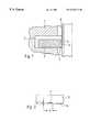
- FIG. 1shows a sectional side view of a piston ring as defined by the invention.
- FIG. 2shows a side view of a cutout of the piston ring.
- a piston ring 3(compression ring) is supported in an annular groove 2 .
- Said piston ringrests against the cylinder wall 5 with its running surface 4 .
- the approximately radially extending channels 7are worked into the lower flank 6 and are uniformly distributed over the circumference.
- Said channels 7have a typical depth “t” of, for example 1 to 5 ⁇ m (shown in the drawing in a highly exaggerated way), and a width “b” of 2 mm.
- the channels 7are worked into the piston ring 3 in a simple manner and at favorable cost using a laser method, which per se is known. Any bulges that might locally occur in said process next to the channels have no disadvantageous effects.
Landscapes
- Engineering & Computer Science (AREA)
- General Engineering & Computer Science (AREA)
- Mechanical Engineering (AREA)
- Pistons, Piston Rings, And Cylinders (AREA)
Abstract
Description
Applicant claims priority under 35 U.S.C. §119 of German Application No. 198 57 637.4 filed Dec. 14, 1998. Applicant also claims priority under 35 U.S.C. §120 of PCT/DE99/03755 filed Nov. 23, 1999. The international application under PCT article 21(2) was not published in English.
The invention relates to a piston ring, in particular to the compression ring for a piston for internal combustion engines, with the features according to the introductory part ofclaim 1.
Such a piston ring is known, for example from WO 97/11295 A1, in conjunction with which provision is made for radially extending channels that are distributed over the circumference for reducing the difference pressure acting on the compression ring in the lower flank of the piston ring. Such channels have a height of less than 1 mm, preferably of from 0.35 to 0.55 mm. Nothing is stated in said document as to how said channels, which are relatively deep, are produced.
Furthermore, a piston for internal combustion engines is known from DE 42 05 503 A1, where provision is made for a defined type of profiling extending all around the circumference of a compression ring for the purpose of avoiding damage to the flank of an annular groove.
The drawback with said design is the fact that producing such a phonograph record-like profiling in the flank of the annular groove is difficult and requires much expenditure.
Based on the type of prior art specified above and the problem posed when plating of the flank of a piston ring with a material is to be avoided, in particular of the uppermost compression ring, the problem of the invention is to find a means that leads to a corresponding piston ring in a simple manner and at favorable cost.
Said problem is solved with a piston ring with the features according to the characterizing part ofclaim 1.
Further advantageous developments of the invention are contained in the dependent claims.
The invention is explained in greater detail in the following with the help of an exemplified embodiment shown in the drawing, in which:
FIG. 1 shows a sectional side view of a piston ring as defined by the invention; and
FIG. 2 shows a side view of a cutout of the piston ring.
In apiston 1 for, for example an Otto motor made of a light metal alloy, a piston ring3 (compression ring) is supported in anannular groove 2. Said piston ring rests against thecylinder wall 5 with its running surface4. The approximately radially extendingchannels 7 are worked into thelower flank 6 and are uniformly distributed over the circumference.Said channels 7 have a typical depth “t” of, for example 1 to 5 μm (shown in the drawing in a highly exaggerated way), and a width “b” of 2 mm. Thechannels 7 are worked into the piston ring3 in a simple manner and at favorable cost using a laser method, which per se is known. Any bulges that might locally occur in said process next to the channels have no disadvantageous effects.
It has been found that a means was discovered with said features in a simple manner that avoids damage to the groove flank or to material plated to the piston ring.
Claims (3)
1. A piston ring, in particular a compression ring for a piston for internal combustion engines, comprising 10 to 100 channels formed via a laser method and distributed over a circumference of a lower flank of the piston ring, wherein said channels are disposed with regular spacings and extend radially, and wherein said channels have a depth “t” of 0.5 to 15 μm, and a width “b” of 0.05 to 5 mm;
such that said channels avoid damage to a groove of the piston supporting the piston ring and prevent material from being plated-to the piston ring.
2. The piston ring according toclaim 1 , wherein said flank of the piston ring having said channels has an additional sulfur surface coating.
3. The piston ring according toclaim 1 , wherein the piston ring is supported in a piston having a first annular groove with a groove height of 0.8 to 1.8 mm, a top land height of 2 to 10 mm, a ring land height of 2.5 to 7 mm, as well as a flank roughness of Ra<0.3 micron.
Applications Claiming Priority (3)
| Application Number | Priority Date | Filing Date | Title |
|---|---|---|---|
| DE19857637 | 1998-12-14 | ||
| DE19857637ADE19857637A1 (en) | 1998-12-14 | 1998-12-14 | Piston ring for a piston for internal combustion engines |
| PCT/DE1999/003755WO2000036320A1 (en) | 1998-12-14 | 1999-11-23 | Piston ring for the piston of an internal combustion engine |
Publications (1)
| Publication Number | Publication Date |
|---|---|
| US6726217B1true US6726217B1 (en) | 2004-04-27 |
Family
ID=7891032
Family Applications (1)
| Application Number | Title | Priority Date | Filing Date |
|---|---|---|---|
| US09/868,079Expired - LifetimeUS6726217B1 (en) | 1998-12-14 | 1999-11-23 | Piston ring for the piston of an internal combustion engine |
Country Status (6)
| Country | Link |
|---|---|
| US (1) | US6726217B1 (en) |
| EP (1) | EP1141593B1 (en) |
| JP (1) | JP2003512552A (en) |
| BR (1) | BR9916108A (en) |
| DE (2) | DE19857637A1 (en) |
| WO (1) | WO2000036320A1 (en) |
Cited By (1)
| Publication number | Priority date | Publication date | Assignee | Title |
|---|---|---|---|---|
| WO2015021238A1 (en)* | 2013-08-07 | 2015-02-12 | Federal-Mogul Corporation | Piston ring |
Families Citing this family (3)
| Publication number | Priority date | Publication date | Assignee | Title |
|---|---|---|---|---|
| WO2004090389A1 (en)* | 2003-04-10 | 2004-10-21 | Man B & W Diesel A/S | A piston ring for an internal combustion engine |
| WO2004111503A1 (en)* | 2003-06-14 | 2004-12-23 | Man B & W Diesel A/S | Reciprocating piston engine |
| CN102072041A (en)* | 2011-01-12 | 2011-05-25 | 江门市中港宝田摩托车实业有限公司 | Lightweight piston for motorcycle engine |
Citations (13)
| Publication number | Priority date | Publication date | Assignee | Title |
|---|---|---|---|---|
| US384272A (en)* | 1888-06-12 | Jefferson patten | ||
| US1489335A (en)* | 1920-06-17 | 1924-04-08 | Seifert Henry Richard | Piston ring |
| US3627336A (en)* | 1967-06-27 | 1971-12-14 | Gordon C Lawson | Extrusion resistant pressure ring assembly for slidably telescoping members |
| US4300494A (en)* | 1979-09-26 | 1981-11-17 | Shell Oil Company | Thermal insulated intake ports |
| US4359229A (en) | 1979-06-01 | 1982-11-16 | Leopoldo Cattaneo | Piston rings with control slits |
| DE3634708A1 (en) | 1986-10-11 | 1988-04-28 | Goetze Ag | Machine component exposed to sliding friction, such as, in particular, a piston ring |
| US4835856A (en) | 1986-07-05 | 1989-06-06 | Sanden Corporation | Piston ring manufacturing method |
| DE3934795C1 (en) | 1989-10-19 | 1991-06-13 | Friedhelm 5090 Leverkusen De Stecher | Piston ring and piston groove - has radial passages in piston ring lower flank, unconnected in peripheral direction |
| DE4205503A1 (en) | 1992-02-22 | 1993-08-26 | Mahle Gmbh | PISTON FOR COMBUSTION ENGINES |
| US5241748A (en) | 1991-06-27 | 1993-09-07 | Teikoku Piston Ring Co., Ltd. | Method for manufacturing a compression ring |
| JPH05340473A (en) | 1992-06-01 | 1993-12-21 | Nippon Steel Corp | Piston ring and machining method thereof |
| WO1997011295A1 (en) | 1995-09-22 | 1997-03-27 | Man B & W Diesel A/S | A piston ring for a piston in an internal combustion engine |
| DE19720779C1 (en) | 1997-05-17 | 1998-10-01 | Ae Goetze Gmbh | Cast iron piston ring |
Family Cites Families (5)
| Publication number | Priority date | Publication date | Assignee | Title |
|---|---|---|---|---|
| JPH02120575A (en)* | 1988-10-29 | 1990-05-08 | Riken Corp | Piston ring |
| JPH05215239A (en)* | 1991-08-07 | 1993-08-24 | Riken Corp | Piston ring |
| JPH05215238A (en)* | 1991-10-30 | 1993-08-24 | Riken Corp | Piston ring |
| JPH06159135A (en)* | 1992-11-24 | 1994-06-07 | Riken Corp | Compression ring |
| JPH10238630A (en)* | 1997-02-27 | 1998-09-08 | Nippon Piston Ring Co Ltd | Piston ring for internal combustion engine |
- 1998
- 1998-12-14DEDE19857637Apatent/DE19857637A1/ennot_activeWithdrawn
- 1999
- 1999-11-23BRBR9916108-7Apatent/BR9916108A/ennot_activeIP Right Cessation
- 1999-11-23EPEP99962077Apatent/EP1141593B1/ennot_activeRevoked
- 1999-11-23WOPCT/DE1999/003755patent/WO2000036320A1/enactiveIP Right Grant
- 1999-11-23JPJP2000588528Apatent/JP2003512552A/enactivePending
- 1999-11-23USUS09/868,079patent/US6726217B1/ennot_activeExpired - Lifetime
- 1999-11-23DEDE59906713Tpatent/DE59906713D1/ennot_activeExpired - Lifetime
Patent Citations (13)
| Publication number | Priority date | Publication date | Assignee | Title |
|---|---|---|---|---|
| US384272A (en)* | 1888-06-12 | Jefferson patten | ||
| US1489335A (en)* | 1920-06-17 | 1924-04-08 | Seifert Henry Richard | Piston ring |
| US3627336A (en)* | 1967-06-27 | 1971-12-14 | Gordon C Lawson | Extrusion resistant pressure ring assembly for slidably telescoping members |
| US4359229A (en) | 1979-06-01 | 1982-11-16 | Leopoldo Cattaneo | Piston rings with control slits |
| US4300494A (en)* | 1979-09-26 | 1981-11-17 | Shell Oil Company | Thermal insulated intake ports |
| US4835856A (en) | 1986-07-05 | 1989-06-06 | Sanden Corporation | Piston ring manufacturing method |
| DE3634708A1 (en) | 1986-10-11 | 1988-04-28 | Goetze Ag | Machine component exposed to sliding friction, such as, in particular, a piston ring |
| DE3934795C1 (en) | 1989-10-19 | 1991-06-13 | Friedhelm 5090 Leverkusen De Stecher | Piston ring and piston groove - has radial passages in piston ring lower flank, unconnected in peripheral direction |
| US5241748A (en) | 1991-06-27 | 1993-09-07 | Teikoku Piston Ring Co., Ltd. | Method for manufacturing a compression ring |
| DE4205503A1 (en) | 1992-02-22 | 1993-08-26 | Mahle Gmbh | PISTON FOR COMBUSTION ENGINES |
| JPH05340473A (en) | 1992-06-01 | 1993-12-21 | Nippon Steel Corp | Piston ring and machining method thereof |
| WO1997011295A1 (en) | 1995-09-22 | 1997-03-27 | Man B & W Diesel A/S | A piston ring for a piston in an internal combustion engine |
| DE19720779C1 (en) | 1997-05-17 | 1998-10-01 | Ae Goetze Gmbh | Cast iron piston ring |
Cited By (4)
| Publication number | Priority date | Publication date | Assignee | Title |
|---|---|---|---|---|
| WO2015021238A1 (en)* | 2013-08-07 | 2015-02-12 | Federal-Mogul Corporation | Piston ring |
| CN105518356A (en)* | 2013-08-07 | 2016-04-20 | 费德罗-莫格尔公司 | Piston ring |
| US9423028B2 (en) | 2013-08-07 | 2016-08-23 | Federal-Mogul Corporation | Piston ring |
| CN105518356B (en)* | 2013-08-07 | 2017-12-22 | 费德罗-莫格尔公司 | Piston ring |
Also Published As
| Publication number | Publication date |
|---|---|
| DE59906713D1 (en) | 2003-09-25 |
| DE19857637A1 (en) | 2000-06-15 |
| EP1141593B1 (en) | 2003-08-20 |
| WO2000036320A1 (en) | 2000-06-22 |
| EP1141593A1 (en) | 2001-10-10 |
| JP2003512552A (en) | 2003-04-02 |
| BR9916108A (en) | 2001-09-04 |
Similar Documents
| Publication | Publication Date | Title |
|---|---|---|
| CN100347432C (en) | Multipart cooling piston for an internal combustion engine and method for its manufacture | |
| US8631736B2 (en) | Two-part piston for an internal combustion engine | |
| EP2206909B1 (en) | Piston device for internal combustion engines | |
| CN1473250A (en) | steel piston ring | |
| EP2318681B1 (en) | Piston skirt with friction reducing oil recess and oil reservoir | |
| US5323744A (en) | Piston for internal combustion engines | |
| KR20030061452A (en) | Cooling duct piston for a direct-injection diesel engine | |
| US20020033579A1 (en) | Piston ring | |
| JP5907955B2 (en) | Oil control ring with iron body for internal combustion engine | |
| CN1685142A (en) | One-part cooling channel pistons for internal combustion engines | |
| US6726217B1 (en) | Piston ring for the piston of an internal combustion engine | |
| CN1806112A (en) | Piston for an internal combustion engine | |
| US6488000B2 (en) | Cylinder block for an internal combustion engine | |
| US7975601B2 (en) | Engine cylinder liner | |
| JPH05340300A (en) | Piston of combustion engine | |
| US4664021A (en) | Treatment of pistons | |
| US11371610B2 (en) | Flutter-suppression piston ring | |
| JPH09257130A (en) | Internal combustion engine piston ring | |
| US20060112924A1 (en) | Cylinder liner for a cylinder crankcase | |
| US6837146B2 (en) | Piston for internal combustion engines | |
| WO2021050471A1 (en) | Coated piston ring for an internal combustion engine | |
| KR100489134B1 (en) | Embossing skirt piston for offset crankshaft | |
| WO2020180925A1 (en) | Piston ring with inlaid dlc coating and method of manufacturing | |
| EP0840039A3 (en) | Oil control ring of two piece type for internal combustion engine | |
| CN220726439U (en) | Bottom chamfering structure of cylinder hole |
Legal Events
| Date | Code | Title | Description |
|---|---|---|---|
| AS | Assignment | Owner name:MAHLE GMBH, GERMANY Free format text:ASSIGNMENT OF ASSIGNORS INTEREST;ASSIGNOR:ISSLER, WOLFGANG;REEL/FRAME:012001/0354 Effective date:20010613 | |
| STCF | Information on status: patent grant | Free format text:PATENTED CASE | |
| FPAY | Fee payment | Year of fee payment:4 | |
| FPAY | Fee payment | Year of fee payment:8 | |
| FPAY | Fee payment | Year of fee payment:12 |