US6726042B2 - Tamper evident closure - Google Patents
Tamper evident closureDownload PDFInfo
- Publication number
- US6726042B2 US6726042B2US10/043,447US4344702AUS6726042B2US 6726042 B2US6726042 B2US 6726042B2US 4344702 AUS4344702 AUS 4344702AUS 6726042 B2US6726042 B2US 6726042B2
- Authority
- US
- United States
- Prior art keywords
- container
- skirt
- segment
- expansion
- closure
- Prior art date
- Legal status (The legal status is an assumption and is not a legal conclusion. Google has not performed a legal analysis and makes no representation as to the accuracy of the status listed.)
- Expired - Fee Related
Links
Images


Classifications
- B—PERFORMING OPERATIONS; TRANSPORTING
- B65—CONVEYING; PACKING; STORING; HANDLING THIN OR FILAMENTARY MATERIAL
- B65D—CONTAINERS FOR STORAGE OR TRANSPORT OF ARTICLES OR MATERIALS, e.g. BAGS, BARRELS, BOTTLES, BOXES, CANS, CARTONS, CRATES, DRUMS, JARS, TANKS, HOPPERS, FORWARDING CONTAINERS; ACCESSORIES, CLOSURES, OR FITTINGS THEREFOR; PACKAGING ELEMENTS; PACKAGES
- B65D41/00—Caps, e.g. crown caps or crown seals, i.e. members having parts arranged for engagement with the external periphery of a neck or wall defining a pouring opening or discharge aperture; Protective cap-like covers for closure members, e.g. decorative covers of metal foil or paper
- B65D41/32—Caps or cap-like covers with lines of weakness, tearing-strips, tags, or like opening or removal devices, e.g. to facilitate formation of pouring openings
- B65D41/34—Threaded or like caps or cap-like covers provided with tamper elements formed in, or attached to, the closure skirt
- B65D41/3442—Threaded or like caps or cap-like covers provided with tamper elements formed in, or attached to, the closure skirt with rigid bead or projections formed on the tamper element and coacting with bead or projections on the container
- B65D41/3447—Threaded or like caps or cap-like covers provided with tamper elements formed in, or attached to, the closure skirt with rigid bead or projections formed on the tamper element and coacting with bead or projections on the container the tamper element being integrally connected to the closure by means of bridges
- Y—GENERAL TAGGING OF NEW TECHNOLOGICAL DEVELOPMENTS; GENERAL TAGGING OF CROSS-SECTIONAL TECHNOLOGIES SPANNING OVER SEVERAL SECTIONS OF THE IPC; TECHNICAL SUBJECTS COVERED BY FORMER USPC CROSS-REFERENCE ART COLLECTIONS [XRACs] AND DIGESTS
- Y10—TECHNICAL SUBJECTS COVERED BY FORMER USPC
- Y10S—TECHNICAL SUBJECTS COVERED BY FORMER USPC CROSS-REFERENCE ART COLLECTIONS [XRACs] AND DIGESTS
- Y10S215/00—Bottles and jars
- Y10S215/901—Tamper-resistant structure
Definitions
- This inventionrelates to enclosures for containers, and more particularly to closures which indicate an initial opening of the container.
- tamper evident closuresare well known in the art, including closures for containers having external screw threads near the opening of the container, such as bottles and jars.
- tamper evident closureshave a cap and a tamper evident band which is frangibly connected to the cap. When the closure is initially removed from a container, the frangible connection breaks to separate the tamper evident band from the cap to indicate that the container has been opened.
- the captypically includes a threaded portion having interior screw threads, or thread segments, which mate with the screw threads of the container to permit the closure to be screwed onto the container and thereby seal the container.
- the tamper evident bandgenerally includes one or more ribs which protrude inwardly of the band to engage a retaining flange on the container which is generally positioned beneath the screw threads of the container.
- a need exists for a tamper evident closurewhich may be easily and quickly installed onto a container without rupturing the frangible connections between the cap portion and the tamper evident band of the closure, while providing a reliable indication of an initial opening of the container.
- the present inventionprovides a tamper evident closure which may be initially installed onto a container without damaging the tamper evident feature, yet provides a reliable indication of a first opening of the container.
- the closureincludes at least one expansion segment on a tamper evident band of the closure which permits the band to be initially installed over a retaining flange on a container without breaking frangible connections between the band and a cap of the closure.
- the expansion segmentpermits closures to be quickly installed on containers and are therefore suitable for use in typical production lines.
- a closure of the present inventionincludes a cap portion and a tamper evident band portion connected by a series of frangible bridges.
- the cap portion of the closureincludes interior threads which permit the closure to be screwed onto a container having corresponding screw threads on a neck of the container.
- the tamper evident bandis made up of several segments formed together into a unitary piece.
- the bandincludes container engaging segments which mate with a retaining flange on a container, and expansion segments which stretch during an initial installation of the closure on the container to permit the closure to be installed without breaking the frangible bridges.
- the container engaging segmentshave raised ribs which are configured to engage the retaining flange of the container.
- the ribsare generally triangular in shape, with a flat surface to engage the retaining flange and a sloped surface which facilitates installation of the band over the retaining flange.
- the raised ribsextend continuously along the lengths of the container engaging segments.
- each container engaging segmenthas two raised ribs.
- the container engaging segmentshave a single raised rib.
- the expansion segmentsare positioned between the container engaging segments and do not have raised ribs for engaging the retaining flange of the container.
- the container engaging segmentsdefine a peripheral boundary and the expansion segments extend arcuately from the peripheral boundary to create discontinuities in the tamper evident band.
- the container engaging segments and the expansion segmentsare formed integrally and no subsequent operations are required to create the expansion segment, such as forming slits in the band.
- a tamper evident container systemin another aspect of the invention, includes a container and a tamper evident closure.
- the containerhas an opening and screw threads near the opening for receiving the closure.
- the closurecomprises a cap, with screw threads which mate with the screw threads on the container, and a tamper evident band made up of container engaging segments and expansion segments. The expansion segments permit the closure to be initially installed to the container without damaging the tamper evident features of the closure.
- a method for installing a tamper evident closure on a containerincludes the steps of positioning the closure on an opening of the container and turning the closure to screw the closure onto the container and expand expansion segments on a tamper evident band of the closure, whereby the closure is secured on the container without breaking frangible connections on the band.
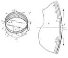
- FIG. 1is a perspective view of an exemplary embodiment of a tamper evident closure, according to the principles of the present invention
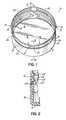
- FIG. 2is a partial cross-sectional view of the tamper evident closure of FIG. 1 taken along line 2 — 2 ;
- FIG. 3is a partial cross-sectional view depicting the tamper evident band of the present invention being installed over a retaining flange of a container;
- FIG. 4shows a partial cross-sectional view of the tamper evident band of FIG. 3 with the raised ribs in position over the retaining flange of a container;
- FIG. 5is a partial plan view of the tamper evident closure of FIG. 1 taken along line 5 — 5 and depicting an expansion of the tamper evident band in phantom;
- FIG. 5Ais a view similar to FIG. 4 of an alternative embodiment of this invention.
- FIGS. 1 and 2an exemplary embodiment of a tamper evident closure 10 including a cap 12 and a tamper evident band 14 according to the principles of the present invention is shown.
- the closure 10comprises an end wall 16 and at least one skirt 18 adjacent to the end wall 16 to define the cap portion 12 of the closure 10 .
- the closure 10is generally circular in shape and has a single skirt 18 .
- Screw threads or screw thread segments 20are disposed on an inwardly facing portion of the skirt 18 and are configured to engage corresponding threads on the necked opening of a container.
- the skirt 18has a terminal edge 22 opposite the end wall 16 , as shown most clearly in FIG. 2 .
- the closure 10also includes a tamper evident band 14 which is connected to the terminal edge 22 of the skirt 18 by a series of frangible bridge elements 24 disposed around the terminal edge 22 of the skirt 18 .
- the tamper evident band 14is made up of several segments joined together around the terminal edge 22 of the skirt 18 .
- the band 14includes several container engaging segments 26 which are configured to engage a retaining flange on the container.
- raised ribs 28are disposed on an inward facing surface of the container engaging segments 26 and are configured to engage the retaining flange of the container.
- the raised ribs 28are continuous along the entire length of the container engaging segments 26 .
- the tamper evident band 14also includes expansion segments 30 connected to and disposed between the container engaging segments 26 .
- the expansion segments 30may be integrally formed with the container engaging segments 26 , but the expansion segments 30 do not have raised ribs for engaging the retaining flange of the container. As shown in FIGS. 1 and 5, each expansion segment 30 has a tapered and raised exterior face 31 relative to the perimeter of the engaging segments 26 of the band 14 .
- the closure 10has four container engaging segments 26 spaced around the terminal edge 22 of the skirt 18 , and four expansion segments 30 evenly spaced around the terminal edge 22 of the skirt 18 and positioned between the container engaging segments 26 .
- container engaging segments 26 and expansion segments 30may be used without departing from the scope of the invention, but the closure 10 should have at least one container engaging segment 26 and at least one expansion segment 30 .
- the expansion segments 30 of the exemplary embodimentextend arcuately out from a peripheral boundary defined by the group of container engaging segments 26 , creating a discontinuity between the container engaging segments 26 .
- the expansion segments 30 , the container engaging segments 26 , and the frangible bridges 24are integrally formed with the cap portion 12 of the closure 10 .
- the entire closure 10may be formed in a single molding operation without the need for subsequent operations, such as slitting.
- a presently preferred method and system of making the closureis disclosed in U.S. Pat. No. 6,099,785, which is hereby incorporated by reference entirely.
- the expansion segments 30permit the closure 10 to be applied to a container for an initial closing of the container without breaking the frangible bridge elements 24 connecting the tamper evident band 14 to the cap portion 12 of the closure 10 .
- FIGS. 3 through 5the initial installation of the closure 10 of the present invention will now be described.
- the closure 10is placed on the opening of the container 40 to engage the screw threads 20 of the closure 10 with the screw threads (not shown) of the container 40 , the raised ribs 28 on the container engaging segments 26 of the closure 10 are brought into contact with a retaining flange 42 on the container 40 .
- FIGS. 1In the exemplary embodiment shown in FIGS.
- the closure 10includes two raised ribs 28 disposed on the container engaging segment 26 of the closure 10 , whereby the retaining flange 42 is positioned between the raised ribs 28 when the closure 10 is fully secured on the container 40 .
- the closure 10may have only one rib 28 , or it may have more than two ribs 28 .
- the raised ribs 28are shaped to permit the ribs 28 to slide over the retaining flange 42 of the container 40 while the closure 10 is being screwed onto the container 40 , but to resist movement of the closure 10 away from the container 40 and back over the retaining flange 42 when the closure 10 is turned to remove the closure 10 from the container 40 .
- FIGS. 1-10In the exemplary embodiment shown in FIGS.
- the raised ribs 28have a generally triangular shape in cross-section, with a sloped surface 44 facing in a direction generally away from the end wall 16 and a generally planar engaging surface 46 facing in a direction generally parallel to and toward the end wall 16 of the closure 10 .
- the sloped edge 44permits the ribs 28 to pass over the retaining flange 42 when the closure 10 is screwed onto the container 40 and the generally flat edge 46 resists the motion of the tamper evident band 14 away from the container when the closure 10 is screwed off of the container 40 .
- the container 40may have a retaining flange 42 a with a truncated triangular configuration, including a downward sloping face 43 , an outer face 45 and a lower face 47 .
- the raised rib(s) 28 ahas a planar engaging surface 46 a on the tamper evident band 14 confronting the face 47 once the closure is initially installed on the container 40 .
- the rib 28 aalso has an outer face 49 and an upwardly sloping face 44 a.
- the expansion segment 30stretches to expand the tamper evident band 14 circumferentially and to permit the raised rib 28 , 28 a to pass over the retaining flange 42 , 42 a without breaking the frangible bridges 24 connecting the tamper evident band 14 to the cap portion 12 of the closure 10 .
- This stretching of the expansion segment 30works in conjunction with the shape of the raised ribs 28 , 28 a to permit the closure 10 to be initially installed on a container 40 without breaking the frangible bridges 24 connecting the tamper evident band 14 to the cap portion 12 .
- the expansion segment 30contracts toward its initial length to secure the tamper evident band 14 proximate the retaining flange 42 , 42 a .
- the raised ribs 28 , 28 aengage the retaining flange 42 , 42 a to prevent the band 14 from moving with the cap 12 .
- the frangible bridges 24break and the band 14 is separated from the cap 12 .
Landscapes
- Engineering & Computer Science (AREA)
- Mechanical Engineering (AREA)
- Closures For Containers (AREA)
Abstract
Description
Claims (11)
Priority Applications (1)
| Application Number | Priority Date | Filing Date | Title |
|---|---|---|---|
| US10/043,447US6726042B2 (en) | 2002-01-10 | 2002-01-10 | Tamper evident closure |
Applications Claiming Priority (1)
| Application Number | Priority Date | Filing Date | Title |
|---|---|---|---|
| US10/043,447US6726042B2 (en) | 2002-01-10 | 2002-01-10 | Tamper evident closure |
Publications (2)
| Publication Number | Publication Date |
|---|---|
| US20030127418A1 US20030127418A1 (en) | 2003-07-10 |
| US6726042B2true US6726042B2 (en) | 2004-04-27 |
Family
ID=21927220
Family Applications (1)
| Application Number | Title | Priority Date | Filing Date |
|---|---|---|---|
| US10/043,447Expired - Fee RelatedUS6726042B2 (en) | 2002-01-10 | 2002-01-10 | Tamper evident closure |
Country Status (1)
| Country | Link |
|---|---|
| US (1) | US6726042B2 (en) |
Cited By (9)
| Publication number | Priority date | Publication date | Assignee | Title |
|---|---|---|---|---|
| US20060043051A1 (en)* | 2002-07-11 | 2006-03-02 | Bissett Andrew S | Fast fit bottle mount |
| US20070251911A1 (en)* | 2006-04-28 | 2007-11-01 | Berry Plastics Corporation | Tamper-evident closure with directional molded retention tabs |
| USD723919S1 (en) | 2013-10-24 | 2015-03-10 | Silgan White Cap LLC | Closure |
| US20170305615A1 (en)* | 2014-10-07 | 2017-10-26 | Stanpac Inc. | Tamper Evident Lid and Method of Making Same |
| US11059633B2 (en) | 2019-10-31 | 2021-07-13 | Cheer Pack North America | Flip-top closure for container |
| US20220363446A1 (en)* | 2021-05-12 | 2022-11-17 | Paul Bradley Forrest | Releasable container cap |
| US20230142631A1 (en)* | 2020-03-27 | 2023-05-11 | Jose Francisco Gonzalez Sanchez | Closing Cap for Containers |
| US20230234754A1 (en)* | 2018-08-29 | 2023-07-27 | Niagara Bottling, Llc | Threaded tamper evidence finish and closure for container |
| US20240076109A1 (en)* | 2021-05-12 | 2024-03-07 | Paul Bradley Forrest | Releasable container cap |
Families Citing this family (9)
| Publication number | Priority date | Publication date | Assignee | Title |
|---|---|---|---|---|
| DE10328179A1 (en)* | 2003-06-16 | 2005-01-20 | Alcoa Deutschland Gmbh | Closing system and method for closing containers |
| US12263994B2 (en)* | 2012-11-01 | 2025-04-01 | Niagara Bottling, Llc | Extended thread tamper band evidence |
| CN106255649B (en)* | 2014-04-24 | 2019-03-22 | 奥布里斯特封闭瑞士有限公司 | About or to tamper-evident sealing improvement |
| US11214410B2 (en) | 2016-02-02 | 2022-01-04 | Niagara Bottling, Llc | Tamper evidence container closure |
| BR112018015742A2 (en) | 2016-02-02 | 2019-01-08 | Clarke Hanan Jay | tamper evidence bridges |
| WO2019058550A1 (en)* | 2017-09-25 | 2019-03-28 | 日本山村硝子株式会社 | Synthetic resin cap and container |
| JPWO2019073794A1 (en)* | 2017-10-10 | 2020-09-24 | 日本山村硝子株式会社 | Synthetic resin caps and containers |
| AU2019312561B2 (en) | 2018-07-30 | 2025-05-29 | Niagara Bottling, Llc | Container preform with threaded tamper evidence finish |
| US11597556B2 (en) | 2018-07-30 | 2023-03-07 | Niagara Bottling, Llc | Container preform with tamper evidence finish portion |
Citations (17)
| Publication number | Priority date | Publication date | Assignee | Title |
|---|---|---|---|---|
| US3455478A (en) | 1967-07-21 | 1969-07-15 | Roehr Metals & Plastics Co | Tamper-indicating closure |
| US4352436A (en) | 1980-11-28 | 1982-10-05 | Consumers Glass Company Limited | Pilferproof cap |
| DE3233806A1 (en)* | 1982-09-11 | 1984-03-15 | Hans 8801 Schillingsfürst Heinlein | Closure cap, preferably with tamper-proof safeguard |
| US4505401A (en) | 1983-06-01 | 1985-03-19 | Wicanders Ab | Screw cap with security ring |
| US4529096A (en) | 1982-06-07 | 1985-07-16 | Consumers Glass Company Limited | Pilferproof cap |
| US4625875A (en) | 1985-02-04 | 1986-12-02 | Carr Joseph J | Tamper-evident closure |
| US4907708A (en) | 1989-01-11 | 1990-03-13 | General Kap Corporation | Double bead track cap system |
| WO1994002371A1 (en) | 1992-07-16 | 1994-02-03 | Precision Valve Australia Pty Ltd | Tamper evident closure |
| US5295600A (en) | 1993-02-25 | 1994-03-22 | Owens-Illinois Closure Inc. | Tamper indicating closure |
| WO1994014674A1 (en) | 1992-12-21 | 1994-07-07 | Zapata Industries, Inc. | Tamper evident plastic closure |
| US5487481A (en) | 1994-10-31 | 1996-01-30 | Sander; Dieter | Tamper evident plastic closure |
| US5893474A (en)* | 1994-06-24 | 1999-04-13 | Crown Cork Ag | Screw cap with anti-tamper strip |
| US5992657A (en) | 1998-05-28 | 1999-11-30 | Rexam Plastics Inc. | Safety closure having tamper-indicating means |
| US6068151A (en) | 1998-08-03 | 2000-05-30 | Fabricas Monterrey, S.A. De C.V. | Tamper-indicating plastic closure having pilfer band |
| US6099785A (en) | 1998-03-17 | 2000-08-08 | Schweigert; Lothar | Method for injection molding plastic closures |
| US20010002661A1 (en)* | 1999-06-03 | 2001-06-07 | Bryan L. Reidenbach | Tamper-resistant bottle closure |
| US6264052B1 (en)* | 1997-01-09 | 2001-07-24 | Cct Creative Closure Technology Gmbh | Screw-type cap including an expandable tamperproof strip |
- 2002
- 2002-01-10USUS10/043,447patent/US6726042B2/ennot_activeExpired - Fee Related
Patent Citations (19)
| Publication number | Priority date | Publication date | Assignee | Title |
|---|---|---|---|---|
| US3455478A (en) | 1967-07-21 | 1969-07-15 | Roehr Metals & Plastics Co | Tamper-indicating closure |
| US4352436A (en) | 1980-11-28 | 1982-10-05 | Consumers Glass Company Limited | Pilferproof cap |
| US4529096A (en) | 1982-06-07 | 1985-07-16 | Consumers Glass Company Limited | Pilferproof cap |
| DE3233806A1 (en)* | 1982-09-11 | 1984-03-15 | Hans 8801 Schillingsfürst Heinlein | Closure cap, preferably with tamper-proof safeguard |
| US4505401A (en) | 1983-06-01 | 1985-03-19 | Wicanders Ab | Screw cap with security ring |
| US4625875A (en) | 1985-02-04 | 1986-12-02 | Carr Joseph J | Tamper-evident closure |
| US4907708A (en) | 1989-01-11 | 1990-03-13 | General Kap Corporation | Double bead track cap system |
| US6089390A (en)* | 1992-07-16 | 2000-07-18 | Closures And Packaging Services Limited | Tamper evident closure |
| WO1994002371A1 (en) | 1992-07-16 | 1994-02-03 | Precision Valve Australia Pty Ltd | Tamper evident closure |
| WO1994014674A1 (en) | 1992-12-21 | 1994-07-07 | Zapata Industries, Inc. | Tamper evident plastic closure |
| US5295600A (en) | 1993-02-25 | 1994-03-22 | Owens-Illinois Closure Inc. | Tamper indicating closure |
| US5893474A (en)* | 1994-06-24 | 1999-04-13 | Crown Cork Ag | Screw cap with anti-tamper strip |
| US5680945A (en) | 1994-10-31 | 1997-10-28 | Sander; Dieter | Tamper evident plastic closure |
| US5487481A (en) | 1994-10-31 | 1996-01-30 | Sander; Dieter | Tamper evident plastic closure |
| US6264052B1 (en)* | 1997-01-09 | 2001-07-24 | Cct Creative Closure Technology Gmbh | Screw-type cap including an expandable tamperproof strip |
| US6099785A (en) | 1998-03-17 | 2000-08-08 | Schweigert; Lothar | Method for injection molding plastic closures |
| US5992657A (en) | 1998-05-28 | 1999-11-30 | Rexam Plastics Inc. | Safety closure having tamper-indicating means |
| US6068151A (en) | 1998-08-03 | 2000-05-30 | Fabricas Monterrey, S.A. De C.V. | Tamper-indicating plastic closure having pilfer band |
| US20010002661A1 (en)* | 1999-06-03 | 2001-06-07 | Bryan L. Reidenbach | Tamper-resistant bottle closure |
Cited By (15)
| Publication number | Priority date | Publication date | Assignee | Title |
|---|---|---|---|---|
| US20060043051A1 (en)* | 2002-07-11 | 2006-03-02 | Bissett Andrew S | Fast fit bottle mount |
| US20070251911A1 (en)* | 2006-04-28 | 2007-11-01 | Berry Plastics Corporation | Tamper-evident closure with directional molded retention tabs |
| US8302794B2 (en) | 2006-04-28 | 2012-11-06 | Berry Plastics Corporation | Tamper-evident closure with directional molded retention tabs |
| US8584874B2 (en) | 2006-04-28 | 2013-11-19 | Berry Plastics Corporation | Tamper-evident closure with directional molded retention tabs |
| USD723919S1 (en) | 2013-10-24 | 2015-03-10 | Silgan White Cap LLC | Closure |
| US20170305615A1 (en)* | 2014-10-07 | 2017-10-26 | Stanpac Inc. | Tamper Evident Lid and Method of Making Same |
| US20230234754A1 (en)* | 2018-08-29 | 2023-07-27 | Niagara Bottling, Llc | Threaded tamper evidence finish and closure for container |
| US12304698B2 (en) | 2018-08-29 | 2025-05-20 | Niagara Bottling, Llc | Threaded tamper evidence finish and closure for container |
| US11873141B2 (en)* | 2018-08-29 | 2024-01-16 | Niagara Bottling, Llc | Threaded tamper evidence finish and closure for container |
| US11059633B2 (en) | 2019-10-31 | 2021-07-13 | Cheer Pack North America | Flip-top closure for container |
| US20230142631A1 (en)* | 2020-03-27 | 2023-05-11 | Jose Francisco Gonzalez Sanchez | Closing Cap for Containers |
| US11542067B2 (en)* | 2021-05-12 | 2023-01-03 | Paul Bradley Forrest | Releasable container cap |
| US20240076109A1 (en)* | 2021-05-12 | 2024-03-07 | Paul Bradley Forrest | Releasable container cap |
| US20220363446A1 (en)* | 2021-05-12 | 2022-11-17 | Paul Bradley Forrest | Releasable container cap |
| US12351373B2 (en)* | 2021-05-12 | 2025-07-08 | Paul Bradley Forrest | Releasable container cap |
Also Published As
| Publication number | Publication date |
|---|---|
| US20030127418A1 (en) | 2003-07-10 |
Similar Documents
| Publication | Publication Date | Title |
|---|---|---|
| US6726042B2 (en) | Tamper evident closure | |
| EP1256523B1 (en) | Mould for forming tamper evident closure caps | |
| KR100436168B1 (en) | Opening check with stop band | |
| US3329295A (en) | Tamper-indicating closure | |
| US5007545A (en) | Removal resistant member | |
| US4613052A (en) | Tamper-indicating closure, container and combination thereof | |
| EP0117104B1 (en) | Method for manufacturing a tamper evident-closure | |
| EP0166572B1 (en) | Tamper indicating closure with tear-off band | |
| US6793082B1 (en) | Snap-on screw-off closure for use in combination with a container | |
| US4653657A (en) | Tamper indicating package | |
| US5107998A (en) | Tamper proof ring for threaded closures | |
| US4667838A (en) | Tamper-evident closure with ribbed skirt | |
| US7228979B2 (en) | Snap-on screw-off closure with retaining member for tamper-indicating band | |
| US5891380A (en) | Tamper evident caps and methods | |
| CN113788220A (en) | Closure, mold stack, mold and molding system | |
| US4645087A (en) | Tamper indicating device | |
| US5248050A (en) | Cap having expandable guarantee strip | |
| US4333577A (en) | Tamperproof closure | |
| EP0235870B2 (en) | Tamper-evident closures | |
| CN1026309C (en) | Closure with tamper evident band | |
| EP0239176A2 (en) | Tamper-evident closures | |
| MXPA97007176A (en) | Inviolable closure with band caut |
Legal Events
| Date | Code | Title | Description |
|---|---|---|---|
| AS | Assignment | Owner name:DELTA PLASTICS, INC., ARKANSAS Free format text:ASSIGNMENT OF ASSIGNORS INTEREST;ASSIGNORS:SCHWEIGERT, LOTHAR;O, UI HWAN;REEL/FRAME:014166/0457;SIGNING DATES FROM 20030503 TO 20030508 | |
| AS | Assignment | Owner name:MADISON CAPITAL FUNDING, LLC, ILLINOIS Free format text:SECURITY AGREEMENT;ASSIGNOR:DELTA PLASTICS, INC.;REEL/FRAME:014154/0777 Effective date:20030606 | |
| CC | Certificate of correction | ||
| AS | Assignment | Owner name:DELTA PLASTICS, INC., ARKANSAS Free format text:RELEASE BY SECURED PARTY;ASSIGNOR:MADISON CAPITAL FUNDING LLC;REEL/FRAME:016570/0160 Effective date:20050919 | |
| FPAY | Fee payment | Year of fee payment:4 | |
| FEPP | Fee payment procedure | Free format text:PAT HOLDER NO LONGER CLAIMS SMALL ENTITY STATUS, ENTITY STATUS SET TO UNDISCOUNTED (ORIGINAL EVENT CODE: STOL); ENTITY STATUS OF PATENT OWNER: LARGE ENTITY | |
| FPAY | Fee payment | Year of fee payment:8 | |
| AS | Assignment | Owner name:BERRY PLASTICS CORPORATION, INDIANA Free format text:ASSIGNMENT OF ASSIGNORS INTEREST;ASSIGNOR:DELTA PLASTICS INC.;REEL/FRAME:029040/0987 Effective date:20120601 | |
| REMI | Maintenance fee reminder mailed | ||
| LAPS | Lapse for failure to pay maintenance fees | ||
| STCH | Information on status: patent discontinuation | Free format text:PATENT EXPIRED DUE TO NONPAYMENT OF MAINTENANCE FEES UNDER 37 CFR 1.362 | |
| FP | Lapsed due to failure to pay maintenance fee | Effective date:20160427 |