US6725177B2 - System for monitoring connection pattern of data ports - Google Patents
System for monitoring connection pattern of data portsDownload PDFInfo
- Publication number
- US6725177B2 US6725177B2US10/437,653US43765303AUS6725177B2US 6725177 B2US6725177 B2US 6725177B2US 43765303 AUS43765303 AUS 43765303AUS 6725177 B2US6725177 B2US 6725177B2
- Authority
- US
- United States
- Prior art keywords
- socket
- contact
- data ports
- micro
- adapter
- Prior art date
- Legal status (The legal status is an assumption and is not a legal conclusion. Google has not performed a legal analysis and makes no representation as to the accuracy of the status listed.)
- Expired - Lifetime
Links
Images


Classifications
- G—PHYSICS
- G06—COMPUTING OR CALCULATING; COUNTING
- G06F—ELECTRIC DIGITAL DATA PROCESSING
- G06F13/00—Interconnection of, or transfer of information or other signals between, memories, input/output devices or central processing units
- G06F13/10—Program control for peripheral devices
- G06F13/12—Program control for peripheral devices using hardware independent of the central processor, e.g. channel or peripheral processor
- H—ELECTRICITY
- H04—ELECTRIC COMMUNICATION TECHNIQUE
- H04M—TELEPHONIC COMMUNICATION
- H04M3/00—Automatic or semi-automatic exchanges
- H04M3/22—Arrangements for supervision, monitoring or testing
- G—PHYSICS
- G01—MEASURING; TESTING
- G01R—MEASURING ELECTRIC VARIABLES; MEASURING MAGNETIC VARIABLES
- G01R31/00—Arrangements for testing electric properties; Arrangements for locating electric faults; Arrangements for electrical testing characterised by what is being tested not provided for elsewhere
- G01R31/50—Testing of electric apparatus, lines, cables or components for short-circuits, continuity, leakage current or incorrect line connections
- G01R31/66—Testing of connections, e.g. of plugs or non-disconnectable joints
- G01R31/67—Testing the correctness of wire connections in electric apparatus or circuits
- H—ELECTRICITY
- H01—ELECTRIC ELEMENTS
- H01R—ELECTRICALLY-CONDUCTIVE CONNECTIONS; STRUCTURAL ASSOCIATIONS OF A PLURALITY OF MUTUALLY-INSULATED ELECTRICAL CONNECTING ELEMENTS; COUPLING DEVICES; CURRENT COLLECTORS
- H01R13/00—Details of coupling devices of the kinds covered by groups H01R12/70 or H01R24/00 - H01R33/00
- H01R13/66—Structural association with built-in electrical component
- H01R13/70—Structural association with built-in electrical component with built-in switch
- H01R13/703—Structural association with built-in electrical component with built-in switch operated by engagement or disengagement of coupling parts, e.g. dual-continuity coupling part
- H01R13/7036—Structural association with built-in electrical component with built-in switch operated by engagement or disengagement of coupling parts, e.g. dual-continuity coupling part the switch being in series with coupling part, e.g. dead coupling, explosion proof coupling
- H01R13/7038—Structural association with built-in electrical component with built-in switch operated by engagement or disengagement of coupling parts, e.g. dual-continuity coupling part the switch being in series with coupling part, e.g. dead coupling, explosion proof coupling making use of a remote controlled switch, e.g. relais, solid state switch activated by the engagement of the coupling parts
- H—ELECTRICITY
- H01—ELECTRIC ELEMENTS
- H01R—ELECTRICALLY-CONDUCTIVE CONNECTIONS; STRUCTURAL ASSOCIATIONS OF A PLURALITY OF MUTUALLY-INSULATED ELECTRICAL CONNECTING ELEMENTS; COUPLING DEVICES; CURRENT COLLECTORS
- H01R24/00—Two-part coupling devices, or either of their cooperating parts, characterised by their overall structure
- H01R24/38—Two-part coupling devices, or either of their cooperating parts, characterised by their overall structure having concentrically or coaxially arranged contacts
- H01R24/40—Two-part coupling devices, or either of their cooperating parts, characterised by their overall structure having concentrically or coaxially arranged contacts specially adapted for high frequency
- H01R24/52—Two-part coupling devices, or either of their cooperating parts, characterised by their overall structure having concentrically or coaxially arranged contacts specially adapted for high frequency mounted in or to a panel or structure
- H—ELECTRICITY
- H01—ELECTRIC ELEMENTS
- H01R—ELECTRICALLY-CONDUCTIVE CONNECTIONS; STRUCTURAL ASSOCIATIONS OF A PLURALITY OF MUTUALLY-INSULATED ELECTRICAL CONNECTING ELEMENTS; COUPLING DEVICES; CURRENT COLLECTORS
- H01R25/00—Coupling parts adapted for simultaneous co-operation with two or more identical counterparts, e.g. for distributing energy to two or more circuits
- H01R25/006—Coupling parts adapted for simultaneous co-operation with two or more identical counterparts, e.g. for distributing energy to two or more circuits the coupling part being secured to apparatus or structure, e.g. duplex wall receptacle
- H—ELECTRICITY
- H04—ELECTRIC COMMUNICATION TECHNIQUE
- H04Q—SELECTING
- H04Q1/00—Details of selecting apparatus or arrangements
- H04Q1/02—Constructional details
- H04Q1/13—Patch panels for monitoring, interconnecting or testing circuits, e.g. patch bay, patch field or jack field; Patching modules
- H04Q1/135—Patch panels for monitoring, interconnecting or testing circuits, e.g. patch bay, patch field or jack field; Patching modules characterized by patch cord details
- H04Q1/136—Patch panels for monitoring, interconnecting or testing circuits, e.g. patch bay, patch field or jack field; Patching modules characterized by patch cord details having patch field management or physical layer management arrangements
- H—ELECTRICITY
- H01—ELECTRIC ELEMENTS
- H01R—ELECTRICALLY-CONDUCTIVE CONNECTIONS; STRUCTURAL ASSOCIATIONS OF A PLURALITY OF MUTUALLY-INSULATED ELECTRICAL CONNECTING ELEMENTS; COUPLING DEVICES; CURRENT COLLECTORS
- H01R13/00—Details of coupling devices of the kinds covered by groups H01R12/70 or H01R24/00 - H01R33/00
- H01R13/62—Means for facilitating engagement or disengagement of coupling parts or for holding them in engagement
- H01R13/625—Casing or ring with bayonet engagement
- H—ELECTRICITY
- H01—ELECTRIC ELEMENTS
- H01R—ELECTRICALLY-CONDUCTIVE CONNECTIONS; STRUCTURAL ASSOCIATIONS OF A PLURALITY OF MUTUALLY-INSULATED ELECTRICAL CONNECTING ELEMENTS; COUPLING DEVICES; CURRENT COLLECTORS
- H01R2103/00—Two poles
- H—ELECTRICITY
- H01—ELECTRIC ELEMENTS
- H01R—ELECTRICALLY-CONDUCTIVE CONNECTIONS; STRUCTURAL ASSOCIATIONS OF A PLURALITY OF MUTUALLY-INSULATED ELECTRICAL CONNECTING ELEMENTS; COUPLING DEVICES; CURRENT COLLECTORS
- H01R2201/00—Connectors or connections adapted for particular applications
- H01R2201/04—Connectors or connections adapted for particular applications for network, e.g. LAN connectors
- H—ELECTRICITY
- H01—ELECTRIC ELEMENTS
- H01R—ELECTRICALLY-CONDUCTIVE CONNECTIONS; STRUCTURAL ASSOCIATIONS OF A PLURALITY OF MUTUALLY-INSULATED ELECTRICAL CONNECTING ELEMENTS; COUPLING DEVICES; CURRENT COLLECTORS
- H01R24/00—Two-part coupling devices, or either of their cooperating parts, characterised by their overall structure
- H01R24/60—Contacts spaced along planar side wall transverse to longitudinal axis of engagement
- H01R24/62—Sliding engagements with one side only, e.g. modular jack coupling devices
- H01R24/64—Sliding engagements with one side only, e.g. modular jack coupling devices for high frequency, e.g. RJ 45
- H—ELECTRICITY
- H01—ELECTRIC ELEMENTS
- H01R—ELECTRICALLY-CONDUCTIVE CONNECTIONS; STRUCTURAL ASSOCIATIONS OF A PLURALITY OF MUTUALLY-INSULATED ELECTRICAL CONNECTING ELEMENTS; COUPLING DEVICES; CURRENT COLLECTORS
- H01R27/00—Coupling parts adapted for co-operation with two or more dissimilar counterparts
- H01R27/02—Coupling parts adapted for co-operation with two or more dissimilar counterparts for simultaneous co-operation with two or more dissimilar counterparts
- H—ELECTRICITY
- H01—ELECTRIC ELEMENTS
- H01R—ELECTRICALLY-CONDUCTIVE CONNECTIONS; STRUCTURAL ASSOCIATIONS OF A PLURALITY OF MUTUALLY-INSULATED ELECTRICAL CONNECTING ELEMENTS; COUPLING DEVICES; CURRENT COLLECTORS
- H01R29/00—Coupling parts for selective co-operation with a counterpart in different ways to establish different circuits, e.g. for voltage selection, for series-parallel selection, programmable connectors
- H—ELECTRICITY
- H01—ELECTRIC ELEMENTS
- H01R—ELECTRICALLY-CONDUCTIVE CONNECTIONS; STRUCTURAL ASSOCIATIONS OF A PLURALITY OF MUTUALLY-INSULATED ELECTRICAL CONNECTING ELEMENTS; COUPLING DEVICES; CURRENT COLLECTORS
- H01R31/00—Coupling parts supported only by co-operation with counterpart
- H01R31/005—Intermediate parts for distributing signals
- H—ELECTRICITY
- H04—ELECTRIC COMMUNICATION TECHNIQUE
- H04Q—SELECTING
- H04Q1/00—Details of selecting apparatus or arrangements
- H04Q1/02—Constructional details
- H04Q1/14—Distribution frames
- H04Q1/149—Wireguides in connector blocks
- Y—GENERAL TAGGING OF NEW TECHNOLOGICAL DEVELOPMENTS; GENERAL TAGGING OF CROSS-SECTIONAL TECHNOLOGIES SPANNING OVER SEVERAL SECTIONS OF THE IPC; TECHNICAL SUBJECTS COVERED BY FORMER USPC CROSS-REFERENCE ART COLLECTIONS [XRACs] AND DIGESTS
- Y10—TECHNICAL SUBJECTS COVERED BY FORMER USPC
- Y10S—TECHNICAL SUBJECTS COVERED BY FORMER USPC CROSS-REFERENCE ART COLLECTIONS [XRACs] AND DIGESTS
- Y10S439/00—Electrical connectors
- Y10S439/915—Auxiliary device for existing plug
Definitions
- the present inventionrelates to the field of cabled systems and related computer peripheral devices, and more particularly to a system and method for determining interconnection pattern of data ports without requiring special patching cables or patching panels.
- a conductorin order to determine the interconnectivity pattern of the various ports, a conductor needs to interconnect the ports and deliver a signal to the scanner indicating the connection status of a particular port.
- it is actually difficult to provide a conductor for this purposebecause most modern data cables being used to interconnect various devices have to meet a particular pre-determined standard in the industry. So for instance, a standard cable such as RJ45 eight wires per cable, each having an end which is adapted to mate with an RJ45 port. No free wire allows for scanning for interconnectivity.
- the portsneeded to be interconnected via a patch panel which required a special patch cable or an apparatus of internal connections in the patch panels. In any case, the ports could not be connected directly using standard cables. Although the need for and desirability of having a scanner system which can utilize standard cables clearly exist, so far, the industry has been unable to come up with such a system.
- the present inventiondetermines and monitors the connection pattern of data ports which are connected by multiconductor cables without requiring special patch cables or patch panels.
- an electrical conductorneeds to connect one port to the other.
- this principleis well known, in the modem era where many of the standardized cables such as RJ11 and RJ45 are used, it is difficult to provide this dedicated conductor for connectivity-scanning purposes because each of the wires within the cable is used for a standardized purpose which may interfere with the connectivity-scanning operation.
- a dedicated conductorwhich may be attached to an existing cable is provided.
- the conductorinteracts with an adapter board which is attached to a port where the cable is to be connected.
- an adapter jacketis provided which attaches to an RJ45 jack.
- the adapter jacketis attached to the jack at both ends of the cable.
- the additional contact point for the scanning operationis provided via an external contact located on the outside of the adapter jacket.
- An external conductor wireconnects the external contact of the jack at each end of the cable such that the contact at each respective end will be electrically coupled to each other.
- an adapter boardis provided above the port sockets with each of the sockets having a socket contact.
- the socket contactis positioned such that when the RJ45 jack having the adapter jacket is inserted into a socket, the contact of the adapter jacket electrically mates with the socket contact of the adapter board.
- the adapter boardis coupled to an output module and an input module.
- the output driver modulehas a plurality of output drivers, and the receiver module has a plurality of latches (other similar electronic devices can be used instead of latches).
- Each of the socket contactsis uniquely connected to one output driver and one latch.
- the output module and the input moduleare both coupled to a micro-processor which is in turn coupled to a communication interface.
- the systemmay be coupled to a local area network or to a computer to report the information regarding the connection pattern.
- Both the output module and the input modulecan be implemented using standard IC devices.
- the main function of the output moduleis to provide a plurality of output drivers which address the adapter contacts and to send a signal to the contacts when instructed to do so by the micro-processor.
- the main function of the input moduleis to provide a plurality of latches (or other similar devices) which also address the contacts and to receive the signal sent by the output drivers.
- the communication interfacecan also be implemented using standard devices currently available to interface between the micro-processor and local area network and electronic devices.
- the micro-processorhas pre-designated one output driver as a first driver and the socket contact which it is connected to as the first contact.
- the latch in the input module which is connected to the designated first contactis designated as the first latch.
- the port corresponding to the first socket contactis considered to be the first port.
- Another driveris pre-designated as a second driver, and its corresponding socket contact is designated as a second contact and its corresponding latch is designated as a second latch.
- the same designation schemeis applied to third, fourth, fifth, and so on, driver/contact/latch groupings such that all groups are uniquely designated.
- the micro-processorcauses the designated first output driver to send out a pulse signal to the socket contact which the micro-processor has designated as the first contact. This places the first socket contact at a high state, and consequently, also places the first latch in the input module at the high state. After sending out the signal, the micro-processor scans the input module for a latch having a high state. If only the first latch indicates a high, then the micro-processor concludes that no valid connection has been made between the first port and another port.
- port oneindicates a high state, for instance port seven
- the micro-processorconcludes that the port is validly connected to port seven. Once the connectivity state of port one is determined, the result is stored in memory and the same process is repeated for port two and so on until all of the ports' connection status has been determined.
- FIG. 1Ais a perspective illustration of a current RJ45 cable which can be adapted to work with the present system.
- FIG. 1Bis a perspective illustration of the RJ45 cable of FIG. 1A which has been fitted with an adapter jacket of the present invention.
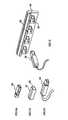
- FIG. 1Cis an isolated perspective illustration of an adapter jacket of the present invention which is adapted for an RJ45 cable jack.
- FIG. 2is a front view of a plurality of RJ45 sockets fitted with an adapter board of the present invention.
- FIG. 3is a simplified schematic illustration of the present connectivity monitoring system.
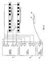
- FIG. 4is a simplified schematic illustration which shows the relationship between the output drivers, the socket contacts, and the receiver latches.
- FIGS. 5, 5 A, 5 B, 5 Cillustrate various other standard cables which can be adapted for use with the present system.
- FIGS. 6, 6 A, 6 B, 6 Cillustrate various other standard cables which can be adapted for use with the present system.
- FIGS. 7, 7 A, 7 B, 7 Cillustrate various other standard cables which can be adapted for use with the present system.
- FIG. 8is a simplified schematic illustration of the present connectivity monitoring system incorporating the optional diagnostic pen.
- FIG. 9is a simplified schematic illustration which shows the relationship between the output drivers, the socket contacts, the receiver latches, and the pen input latch.
- FIG. 10illustrates an embodiment where the external contact is a pin which is supported by a spring.
- FIG. 11illustrates an embodiment where the external contact is placed in the jack itself.
- FIG. 12illustrates adapter strip which is fabricated out of flex tape.
- FIG. 13is a simplified schematic illustration of the present connectivity monitoring system incorporating the optional diagnostic pen and LCD units.
- FIG. 14is a simplified schematic illustration which shows the relationship between the output drivers, the socket contacts, the receiver latches, the pen input latch, and LCD drivers.
- a dedicated conductorwhich may be attached to an existing cable is provided.
- the conductorinteracts with an adapter board which is attached to a port where the cable is to be connected.
- FIG. 1Aa standard RJ45 cable 3 having a jack 5 is shown. Although only one end of the cable is shown here in FIG. 1A for illustration purposes, it should be understood that a similar jack is attached to the other end of the cable.
- the RJ45 jack 5has eight standard contact points 6 .
- an adapter jacket 7FIG. 1C, is provided which attaches to the RJ45 jack as shown in FIG. 1 B.
- the adapter jacketis attached to the jack 5 at both ends of the cable 3 (though only one is shown in the figure).
- the additional contact point for the scanning operationis provided via an external contact 8 located on the outside of the adapter jacket 7 .
- An external conductor wire 9connects the external contact 8 of the jack 5 at each end of the cable 3 such that the contact 8 at each respective end will be electrically coupled to each other.
- a plurality of RJ45 socketsis shown which are standard sockets which mate with a standard RJ45 jack.
- the socketsmay be ports for a network equipment such as a 10 Base-T hub, PABX, and keyphone system, or may be part of a patch panel, though a special patch panel is not required for a successful operation of the present system.
- an adapter board 14is provided above the sockets 12 with each of the sockets 12 having a socket contact 15 .
- the socket contact 15is positioned such that when the RJ45 jack 5 having the adapter jacket 7 , as shown in FIG. 1B, is inserted into a socket 12 of FIG.
- the contact 8 of the adapter jacket 7electrically mates with the socket contact 15 of the adapter board 14 .
- the adapter board 14is shown to carry a plurality of socket contacts 15 , it is entirely possible, and sometimes desirable, to have an adapter board 14 which carries only one socket contact which is used on a single isolated socket.
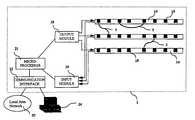
- FIG. 3a simplified schematic illustration of the present system 1 is shown.
- the adapter board 14 of FIG. 2is coupled to an output module 18 and input module 19 .
- the output driver module 18has a plurality of output drivers 20
- the receiver module 19has a plurality of latches 25 (other similar electronic devices can be used instead of latches).
- Each of the socket contacts 15is uniquely connected to one output driver 20 and one latch 25 .
- the output module 18 and the input module 19are both coupled to a micro-processor 21 which is in turn coupled to a communication interface 22 .
- the system 1may be coupled to a local area network 23 or to a computer 24 to report the information regarding connectivity.
- Both the output module and input modulecan be implemented using standard IC devices.
- the main function of the output module 18is to provide a plurality of output drivers 20 which address adapter contacts 15 and to send a signal to the contacts 15 when instructed to do so by the micro-processor 21 .
- the main function of the input module 19is to provide a plurality of latches 25 (or other similar devices) which also address the contacts 15 and to receive the signal sent by the output drivers.
- the communication interface 22can also be implemented using standard devices currently available to interface between the micro-processor 21 and local area network 23 and electronic devices.
- the micro-processor 21has pre-designated one output driver as a first driver and the socket contact which it is connected to as the first contact.
- the latch in the input module 19 which is connected to the designated first contactis designated as the first latch.
- the port corresponding to the first socket contactis considered to be the first port.
- Another driveris pre-designated as a second driver, and its corresponding socket contact is designated as a second contact and its corresponding latch is designated as a second latch.
- the same designation schemeis applied to third, fourth, fifth, and so on, driver/contact/latch groupings such that all groups are uniquely designated.
- the designationsare somewhat arbitrary and the particular designation number or scheme is not important so long as the individual groupings are uniquely traceable by the micro-processor 21 .
- the micro-processor 21causes the designated first output driver to send out a pulse signal to the socket contact 15 which the micro-processor 21 has designated as the first contact. This places the first socket contact at a high state, and consequently, also places the first latch in the input module 19 at the high state. After sending out the signal, the micro-processor 21 scans the input module 19 for a latch having a high state. If only the first latch indicates a high, then the micro-processor 21 concludes that no valid connection has been made between the first port and another port.
- port oneindicates a high state, for instance port seven
- the micro-processor 21concludes that the port 1 is validly connected to port seven. Once the connectivity state of port one is determined, the result is stored in memory and the same process is repeated for port two and so on until all of the ports' connection status has been determined.
- the scheme described aboveis the one employed in the preferred embodiment.
- the advantage of the scheme described aboveis that it allows any port to be connected to any other port. This is unlike patch panel scanning systems where one panel may need to be designated as the input panel, and the other panel is designated as the output panel, and a cable needs to connect a port from the output panel to a port from the input panel. The cable cannot connect, for instance, a port from the input panel to another port from the same input panel.
- This featureis particularly useful for the present invention because no special patch panels are required, and so the ports may be randomly spread out in no particular order.
- the present systemcan optionally include a diagnostic pen which can assist in identifying a port simply by making contact with the socket contact corresponding to the port the user wishes to identify.
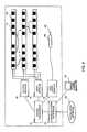
- FIG. 8The block diagram of the present system incorporating this diagnostic pen is shown in FIG. 8 .
- the pen 80has an electrically conductive tip 82 .
- the tip 82is electrically coupled to a pen input module 84 .
- the pen input module 84is communicably coupled to the micro-processor 21 .
- the pen input module 84basically comprise a single latch 27 (or other similar device) for receiving an electrical signal.
- the micro-processor 21To determine which socket contact 15 is making contact with the tip 82 of the diagnostic pen 80 , the micro-processor 21 continually monitors the status of the pen input module 84 . As explained above, the output module continually sends out an electrical signal to each of the socket contacts 15 . Because each of the socket contacts 15 is uniquely addressed at the output module 18 , each socket contact 15 is uniquely traceable. Therefore, the micro-processor 21 is always able to uniquely determine which socket contact 15 is being sent the electrical signal by the output module 18 at any given moment. Initially, when the tip 82 of the pen 80 is not making contact with any of the socket contacts, the pen input module 84 is at a low state because it has not receive any electrical signal.
- the pen input module 84goes high.
- the micro-processor 21is able to determine which socket contact 15 has made contact with the pen tip 82 .
- the data port corresponding to that particular socket contact 15then can be identified.
- the present systemcan optionally further include liquid crystal display (LCD) units 100 for each of the ports as shown in FIG. 13 .
- the LCD units 100are mounted adjacent to the data ports, and are communicably coupled to an LCD module 102 .
- the detailed schematicis shown in FIG. 14 .
- the LCD module 102basically comprise a plurality of output drivers 28 which are uniquely connected to the LCD units 100 .
- the LCD units 100will indicate information about a particular port, or a row of ports. For instance, the LCD unit may indicate the device which is connected to the port, the user name, IP address, etc.
- the LCDmay be used in conjunction with the pen 80 such that by touching the socket contact of a particular port, the micro-processor sends the information about the port to the LCD unit corresponding to the socket contact which made contact with the pen 80 .
- the LCD units 100may also carry an interactive feature where a user can select different options based on a simple menu such as a YES/NO menu scheme where the user can indicate his choice by touching the socket contact (or alternatively a separate dedicated contact pad for the LCD units) with the pen 80 . Although here the LCD units 100 were shown here to be separate units, it should be understood that a single continuous strip of LCD may be used.
- FIGS. 5, 6 , and 7Some such examples are shown in FIGS. 5, 6 , and 7 , where the currently available SC connectors, ST connectors, and BNC connectors, respectively, are fitted with an adapter jacket and their respective ports are provided with an adapter board.
- a standard SC connector 30is fitted with an adapter jacket 31 having a contact 32 to yield an adapted SC connector 33 .
- the SC connector sockets 35have been fitted with adapter boards 34 with adapter contact points 36 .
- a standard ST connector 40is fitted with an adapter jacket 41 having a contact 42 to yield an adapted ST connector 44 .
- the ST connector sockets 45have been fitted with adapter boards 44 with adapter contact points 46 .
- a standard BNC connector 50is fitted with an adapter jacket 51 having a contact 52 to yield an adapted BNC connector 55 .
- the BNC connector sockets 55have been fitted with adapter boards 54 with adapter contact points 56 .
- the external contact 8 of the adapter jacket 7(as shown in FIG. 1C) is in the form of a contact pin 60 as shown in FIG. 10 .
- the pin 60is slidably engaged in a barrel 62 which is placed inside the adapter jacket 64 .
- the contact pin 60is supported by a spring 66 which resides inside the barrel 62 and provides tension to the pin 60 when it is depressed in the direction shown by the arrow 65 .
- the tension provided by the spring 66allows the contact pin 60 to make better contact with the socket contact 15 of the adapter board 14 (FIG. 2 ). It should be appreciated by those skilled in the art that although a spring was shown here, the spring 66 may be replaced with other devices that can provide the necessary tension to the pin 60 .
- the external contactis placed within the standardized jack itself.
- FIG. 11An example of such an embodiment is shown in FIG. 11 .
- the contact pin 70is placed on the RJ45 jack 72 itself. Similar to the embodiment shown in FIG. 10, the contact pin 70 is slidably engaged in a barrel 74 and also supported by a spring 76 . It is to be understood however, that it is possible to have an external contact without the barrel 74 and the spring 76 .
- the socket contactis placed inside the socket itself to make contact with the contact pin 70 .
- a flex tapemay be used to form an adapter strip 90 , as shown in FIG. 12, which is an embodiment of the adapter board.
- the adapter strip 90may be provided with an adhesive such that it can be conveniently pasted adjacent to the sockets.
- the adapter strip 90comprises a main body 92 and a head portion 93 which are fabricated from flex tape which is a common substrate material currently being used to support electronic circuitry.
- the main body 92has a plurality of contacts 94 which are spaced in correspondence with the spacing of the data ports for which the adapter strip is to be placed adjacent to. Two rows of contacts may be provided such as shown in FIG. 12 to accommodate two rows of ports located above and below the adapter strip 90 .
- Each contact 94is connected by a conductor such as a wire which ends in a conductor strip 96 at the head portion 93 .
- the wire strips 96provide a convenient way to electrically mate the adapter strip 90 to the output 18 and input modules 19 .
- the socket contactis in the form of a port or a socket which tightly mates with the external contact.
- the adapter jacketis integrated with the standardized multiconductor cable.
Landscapes
- Engineering & Computer Science (AREA)
- Physics & Mathematics (AREA)
- General Physics & Mathematics (AREA)
- Signal Processing (AREA)
- Computer Networks & Wireless Communication (AREA)
- Theoretical Computer Science (AREA)
- General Engineering & Computer Science (AREA)
- Details Of Connecting Devices For Male And Female Coupling (AREA)
- Coupling Device And Connection With Printed Circuit (AREA)
- Time-Division Multiplex Systems (AREA)
- Structure Of Telephone Exchanges (AREA)
- Maintenance And Management Of Digital Transmission (AREA)
- Communication Control (AREA)
- Use Of Switch Circuits For Exchanges And Methods Of Control Of Multiplex Exchanges (AREA)
- Selective Calling Equipment (AREA)
- Manufacturing Of Electrical Connectors (AREA)
- Testing Of Short-Circuits, Discontinuities, Leakage, Or Incorrect Line Connections (AREA)
- Arrangements For Transmission Of Measured Signals (AREA)
- Information Transfer Systems (AREA)
- Investigation Of Foundation Soil And Reinforcement Of Foundation Soil By Compacting Or Drainage (AREA)
- Communication Cables (AREA)
- Monitoring And Testing Of Transmission In General (AREA)
Abstract
Description
Claims (4)
Priority Applications (2)
| Application Number | Priority Date | Filing Date | Title |
|---|---|---|---|
| US10/437,653US6725177B2 (en) | 1999-04-06 | 2003-05-13 | System for monitoring connection pattern of data ports |
| US10/774,886US7160143B2 (en) | 1999-04-06 | 2004-02-09 | System for monitoring connection pattern of data ports |
Applications Claiming Priority (8)
| Application Number | Priority Date | Filing Date | Title |
|---|---|---|---|
| SG9901521ASG74714A1 (en) | 1999-04-06 | 1999-04-06 | A system for monitoring connection pattern of data ports |
| SG9901521-6 | 1999-04-06 | ||
| SG9901521 | 1999-04-06 | ||
| SG200001891 | 2000-04-05 | ||
| SG200001891-1 | 2000-04-05 | ||
| US09/937,983US6574586B1 (en) | 1999-04-06 | 2000-04-05 | System for monitoring connection pattern of data ports |
| SG200001891ASG74761A1 (en) | 2000-04-05 | 2000-04-05 | A system for monitoring connection pattern of data ports |
| US10/437,653US6725177B2 (en) | 1999-04-06 | 2003-05-13 | System for monitoring connection pattern of data ports |
Related Parent Applications (3)
| Application Number | Title | Priority Date | Filing Date |
|---|---|---|---|
| US09937983Division | 2000-04-05 | ||
| US09/937,983DivisionUS6574586B1 (en) | 1999-04-06 | 2000-04-05 | System for monitoring connection pattern of data ports |
| PCT/SG2000/000045DivisionWO2000060475A1 (en) | 1999-04-06 | 2000-04-05 | A system for monitoring connection pattern of data ports |
Related Child Applications (1)
| Application Number | Title | Priority Date | Filing Date |
|---|---|---|---|
| US10/774,886DivisionUS7160143B2 (en) | 1999-04-06 | 2004-02-09 | System for monitoring connection pattern of data ports |
Publications (2)
| Publication Number | Publication Date |
|---|---|
| US20030204356A1 US20030204356A1 (en) | 2003-10-30 |
| US6725177B2true US6725177B2 (en) | 2004-04-20 |
Family
ID=69399959
Family Applications (3)
| Application Number | Title | Priority Date | Filing Date |
|---|---|---|---|
| US09/937,983Expired - LifetimeUS6574586B1 (en) | 1999-04-06 | 2000-04-05 | System for monitoring connection pattern of data ports |
| US10/437,653Expired - LifetimeUS6725177B2 (en) | 1999-04-06 | 2003-05-13 | System for monitoring connection pattern of data ports |
| US10/774,886Expired - Fee RelatedUS7160143B2 (en) | 1999-04-06 | 2004-02-09 | System for monitoring connection pattern of data ports |
Family Applications Before (1)
| Application Number | Title | Priority Date | Filing Date |
|---|---|---|---|
| US09/937,983Expired - LifetimeUS6574586B1 (en) | 1999-04-06 | 2000-04-05 | System for monitoring connection pattern of data ports |
Family Applications After (1)
| Application Number | Title | Priority Date | Filing Date |
|---|---|---|---|
| US10/774,886Expired - Fee RelatedUS7160143B2 (en) | 1999-04-06 | 2004-02-09 | System for monitoring connection pattern of data ports |
Country Status (31)
| Country | Link |
|---|---|
| US (3) | US6574586B1 (en) |
| EP (5) | EP2228728B1 (en) |
| JP (1) | JP4738601B2 (en) |
| KR (1) | KR100460432B1 (en) |
| CN (1) | CN1142497C (en) |
| AT (3) | ATE433583T1 (en) |
| AU (1) | AU767105B2 (en) |
| BG (1) | BG65360B1 (en) |
| BR (1) | BR0009575A (en) |
| BY (1) | BY6726C1 (en) |
| CA (2) | CA2659706C (en) |
| CY (2) | CY1105840T1 (en) |
| CZ (1) | CZ20013561A3 (en) |
| DE (3) | DE60030707T2 (en) |
| DK (2) | DK1173811T3 (en) |
| ES (2) | ES2272272T3 (en) |
| HK (1) | HK1046962B (en) |
| HR (1) | HRP20010721B1 (en) |
| HU (1) | HUP0200745A2 (en) |
| IL (2) | IL145770A0 (en) |
| LT (1) | LT5017B (en) |
| MX (1) | MXPA01010075A (en) |
| NO (1) | NO20014828L (en) |
| NZ (1) | NZ514611A (en) |
| PL (2) | PL206321B1 (en) |
| PT (2) | PT1173811E (en) |
| RO (1) | RO121496B1 (en) |
| RU (1) | RU2251147C2 (en) |
| TR (1) | TR200103825T2 (en) |
| WO (1) | WO2000060475A1 (en) |
| YU (1) | YU70301A (en) |
Cited By (90)
| Publication number | Priority date | Publication date | Assignee | Title |
|---|---|---|---|---|
| US20020069277A1 (en)* | 2000-11-22 | 2002-06-06 | Caveney Jack E. | Network revision system with local system ports |
| US20040219827A1 (en)* | 1999-04-06 | 2004-11-04 | David Solomon I. | System for monitoring connection pattern of data ports |
| US20050165710A1 (en)* | 2002-02-18 | 2005-07-28 | Unocon Llc C/O Noam Ribon | Network-info device |
| US20050186819A1 (en)* | 2004-01-20 | 2005-08-25 | Frank Velleca | Patch panel system |
| US20050224585A1 (en)* | 2004-04-02 | 2005-10-13 | Durrant Richard C E | Radio frequency identification of a connector by a patch panel or other similar structure |
| US20060040715A1 (en)* | 2004-08-19 | 2006-02-23 | Qijun Chen | System and method for network interface power management |
| US20060094291A1 (en)* | 2004-11-03 | 2006-05-04 | Caveney Jack E | Method and apparatus for patch panel patch cord documentation and revision |
| US20060282529A1 (en)* | 2005-06-14 | 2006-12-14 | Panduit Corp. | Method and apparatus for monitoring physical network topology information |
| US20070013487A1 (en)* | 2005-07-18 | 2007-01-18 | Jan Scholtz | Digital certificate on connectors and other products using RFID tags and/or labels as well as RFID reader/interrogator |
| US20070032124A1 (en)* | 2005-08-08 | 2007-02-08 | Panduit Corp. | Systems and methods for detecting a patch cord end connection |
| US20070117444A1 (en)* | 2005-11-18 | 2007-05-24 | Panduit Corp. | Smart cable provisioning for a patch cord management system |
| US20070132503A1 (en)* | 2005-12-06 | 2007-06-14 | Panduit Corp. | Power patch panel with guided mac capability |
| US20070197094A1 (en)* | 2006-02-08 | 2007-08-23 | The Siemon Company | Contacts For Use In Monitoring Connection Patterns In Data Ports |
| US20070238343A1 (en)* | 2006-03-14 | 2007-10-11 | Frank Velleca | Methods and systems to monitor physical layer connections |
| US20070243725A1 (en)* | 2005-08-26 | 2007-10-18 | Panduit Corp. | Patch Field Documentation and Revision Systems |
| US20070285239A1 (en)* | 2006-06-12 | 2007-12-13 | Easton Martyn N | Centralized optical-fiber-based RFID systems and methods |
| US20080043631A1 (en)* | 2005-05-19 | 2008-02-21 | Panduit Corp. | Method and Apparatus for Documenting Network Paths |
| US20080100467A1 (en)* | 2006-10-31 | 2008-05-01 | Downie John D | Radio frequency identification of component connections |
| US20080214140A1 (en)* | 2005-09-28 | 2008-09-04 | Panduit Corp. | Powered patch panel |
| US20080218355A1 (en)* | 2007-03-09 | 2008-09-11 | Downie John D | Optically addressed RFID elements |
| US7455527B2 (en) | 2004-05-03 | 2008-11-25 | Panduit Corp. | Powered patch panel |
| US7488206B2 (en) | 2006-02-14 | 2009-02-10 | Panduit Corp. | Method and apparatus for patch panel patch cord documentation and revision |
| US7519000B2 (en) | 2002-01-30 | 2009-04-14 | Panduit Corp. | Systems and methods for managing a network |
| US20090186519A1 (en)* | 2008-01-22 | 2009-07-23 | Asustek Computer Inc. | Detecting device and connector module thereof |
| US20090225667A1 (en)* | 1997-11-17 | 2009-09-10 | Adc Telecommunications, Inc. | System and method for electronically identifying connections of a cross-connect system |
| US20100015847A1 (en)* | 2008-02-21 | 2010-01-21 | Panduit Corp. | Intelligent Inter-Connect and Cross-Connect Patching System |
| US7656903B2 (en) | 2002-01-30 | 2010-02-02 | Panduit Corp. | System and methods for documenting networks with electronic modules |
| US20100178058A1 (en)* | 2006-12-14 | 2010-07-15 | Kozischek David R | Rfid systems and methods for optical fiber network deployment and maintenance |
| US7772975B2 (en) | 2006-10-31 | 2010-08-10 | Corning Cable Systems, Llc | System for mapping connections using RFID function |
| US20100211697A1 (en)* | 2009-02-13 | 2010-08-19 | Adc Telecommunications, Inc. | Managed connectivity devices, systems, and methods |
| US20100210134A1 (en)* | 2009-02-19 | 2010-08-19 | Panduit Corp. | Cross connect patch guidance system |
| US20110043333A1 (en)* | 2009-08-21 | 2011-02-24 | Michael German | Systems for Automatically Tracking Patching Connections to Network Devices Using a Separate Control Channel and Related Patching Equipment and Methods |
| US20110043371A1 (en)* | 2009-08-21 | 2011-02-24 | Michael German | Systems, Equipment and Methods for Automatically Tracking Cable Connections and for Identifying Work Area Devices and Related Methods of Operating Communications Networks |
| US20110116748A1 (en)* | 2009-10-16 | 2011-05-19 | Adc Telecommunications, Inc. | Managed connectivity in fiber optic systems and methods thereof |
| US20110185012A1 (en)* | 2010-01-27 | 2011-07-28 | Colley Matthew D | System and method for generating a notification mailing list |
| US20110228473A1 (en)* | 2010-02-12 | 2011-09-22 | Chad Anderson | Communications bladed panel systems |
| US20110235979A1 (en)* | 2010-02-12 | 2011-09-29 | John Anderson | Managed fiber connectivity systems |
| US8142221B2 (en) | 2010-04-19 | 2012-03-27 | Tyco Electronics Corporation | Plug assembly for a connectivity management system |
| US8152560B2 (en) | 2010-04-19 | 2012-04-10 | Tyco Electronics Corporation | Connectivity sensing assembly |
| US8248208B2 (en) | 2008-07-15 | 2012-08-21 | Corning Cable Systems, Llc. | RFID-based active labeling system for telecommunication systems |
| US8264355B2 (en) | 2006-12-14 | 2012-09-11 | Corning Cable Systems Llc | RFID systems and methods for optical fiber network deployment and maintenance |
| US8267706B2 (en) | 2008-11-12 | 2012-09-18 | Panduit Corp. | Patch cord with insertion detection and light illumination capabilities |
| USRE43774E1 (en) | 2007-04-12 | 2012-10-30 | Commscope, Inc. Of North Carolina | Systems and methods of identifying patch cord connections in a communications patching system using common mode transmission |
| US8306935B2 (en) | 2008-12-22 | 2012-11-06 | Panduit Corp. | Physical infrastructure management system |
| US8325770B2 (en) | 2003-08-06 | 2012-12-04 | Panduit Corp. | Network managed device installation and provisioning technique |
| US8477031B2 (en) | 2007-10-19 | 2013-07-02 | Panduit Corp. | Communication port identification system |
| US8565572B2 (en) | 2010-06-23 | 2013-10-22 | Adc Telecommunications, Inc. | Telecommunications assembly |
| US8638651B2 (en) | 2011-01-21 | 2014-01-28 | Commscope, Inc. Of North Carolina | Intelligent patching systems and methods using phantom mode control signals and related communications connectors |
| US8696369B2 (en) | 2010-09-09 | 2014-04-15 | Adc Telecommunications, Inc. | Electrical plug with main contacts and retractable secondary contacts |
| US8715012B2 (en) | 2011-04-15 | 2014-05-06 | Adc Telecommunications, Inc. | Managed electrical connectivity systems |
| US8731405B2 (en) | 2008-08-28 | 2014-05-20 | Corning Cable Systems Llc | RFID-based systems and methods for collecting telecommunications network information |
| US8757895B2 (en) | 2011-04-15 | 2014-06-24 | Adc Telecommunications, Inc. | Managed fiber connectivity systems |
| US8832503B2 (en) | 2011-03-25 | 2014-09-09 | Adc Telecommunications, Inc. | Dynamically detecting a defective connector at a port |
| US8874814B2 (en) | 2010-06-11 | 2014-10-28 | Adc Telecommunications, Inc. | Switch-state information aggregation |
| US8897637B2 (en) | 2009-04-22 | 2014-11-25 | Adc Gmbh | Method and arrangement for identifying at least one object |
| US8992261B2 (en) | 2010-10-22 | 2015-03-31 | Adc Telecommunications, Inc. | Single-piece plug nose with multiple contact sets |
| US8992260B2 (en) | 2009-10-16 | 2015-03-31 | Adc Telecommunications, Inc. | Managed connectivity in electrical systems and methods thereof |
| US9038141B2 (en) | 2011-12-07 | 2015-05-19 | Adc Telecommunications, Inc. | Systems and methods for using active optical cable segments |
| US9054440B2 (en) | 2009-10-19 | 2015-06-09 | Adc Telecommunications, Inc. | Managed electrical connectivity systems |
| US9064022B2 (en) | 2011-05-17 | 2015-06-23 | Adc Telecommunications, Inc. | Component identification and tracking system for telecommunication networks |
| US9081537B2 (en) | 2011-03-25 | 2015-07-14 | Adc Telecommunications, Inc. | Identifier encoding scheme for use with multi-path connectors |
| US9093796B2 (en) | 2012-07-06 | 2015-07-28 | Adc Telecommunications, Inc. | Managed electrical connectivity systems |
| US9203198B2 (en) | 2012-09-28 | 2015-12-01 | Commscope Technologies Llc | Low profile faceplate having managed connectivity |
| US9207417B2 (en) | 2012-06-25 | 2015-12-08 | Adc Telecommunications, Inc. | Physical layer management for an active optical module |
| US9219543B2 (en) | 2012-07-11 | 2015-12-22 | Commscope Technologies Llc | Monitoring optical decay in fiber connectivity systems |
| US9285552B2 (en) | 2013-02-05 | 2016-03-15 | Commscope Technologies Llc | Optical assemblies with managed connectivity |
| US9379501B2 (en) | 2013-02-05 | 2016-06-28 | Commscope Technologies Llc | Optical assemblies with managed connectivity |
| US9380874B2 (en) | 2012-07-11 | 2016-07-05 | Commscope Technologies Llc | Cable including a secure physical layer management (PLM) whereby an aggregation point can be associated with a plurality of inputs |
| US9407510B2 (en) | 2013-09-04 | 2016-08-02 | Commscope Technologies Llc | Physical layer system with support for multiple active work orders and/or multiple active technicians |
| US9423570B2 (en) | 2013-02-05 | 2016-08-23 | Commscope Technologies Llc | Optical assemblies with managed connectivity |
| US9453971B2 (en) | 2012-07-11 | 2016-09-27 | Commscope Technologies Llc | Managed fiber connectivity systems |
| US9473361B2 (en) | 2012-07-11 | 2016-10-18 | Commscope Technologies Llc | Physical layer management at a wall plate device |
| US9470742B2 (en) | 2012-08-03 | 2016-10-18 | Commscope Technologies Llc | Managed fiber connectivity systems |
| US9497098B2 (en) | 2011-03-25 | 2016-11-15 | Commscope Technologies Llc | Event-monitoring in a system for automatically obtaining and managing physical layer information using a reliable packet-based communication protocol |
| US9500814B2 (en) | 2014-03-26 | 2016-11-22 | Commscope Technologies Llc | Optical adapter module with managed connectivity |
| US9544058B2 (en) | 2013-09-24 | 2017-01-10 | Commscope Technologies Llc | Pluggable active optical module with managed connectivity support and simulated memory table |
| US9563832B2 (en) | 2012-10-08 | 2017-02-07 | Corning Incorporated | Excess radio-frequency (RF) power storage and power sharing RF identification (RFID) tags, and related connection systems and methods |
| US9590761B2 (en) | 2011-09-23 | 2017-03-07 | Commscope Technologies Llc | Detective passive RF components using radio frequency identification tags |
| US9678133B2 (en) | 2012-03-12 | 2017-06-13 | Commscope, Inc. Of North Carolina | Intelligent patching systems and methods using electrical cable diagnostic tests and inference-based mapping techniques |
| US9798096B2 (en) | 2014-02-07 | 2017-10-24 | Commscope Technologies Llc | Managed fiber connectivity systems |
| US10153954B2 (en) | 2013-08-14 | 2018-12-11 | Commscope Technologies Llc | Inferring physical layer connection status of generic cables from planned single-end connection events |
| US10234648B2 (en) | 2007-08-06 | 2019-03-19 | Commscope Technologies Llc | Fiber optic enclosure with internal cable spool |
| US10371914B2 (en) | 2011-06-24 | 2019-08-06 | Commscope Technologies Llc | Fiber termination enclosure with modular plate assemblies |
| EP3528405A1 (en) | 2012-07-11 | 2019-08-21 | ADC Telecommunications, INC. | Distributed antenna system with managed connectivity |
| US10545305B2 (en) | 2012-12-19 | 2020-01-28 | CommScope Connectivity Belgium BVBA | Distribution device with incrementally added splitters |
| US10627592B2 (en) | 2007-05-07 | 2020-04-21 | Commscope Technologies Llc | Fiber optic assembly with cable spool |
| US10938167B2 (en) | 2018-03-06 | 2021-03-02 | Commscope Technologies Llc | Automated capture of information about fixed cabling |
| US11113642B2 (en) | 2012-09-27 | 2021-09-07 | Commscope Connectivity Uk Limited | Mobile application for assisting a technician in carrying out an electronic work order |
| US20220320795A1 (en)* | 2019-07-31 | 2022-10-06 | Nexans | Clippable interconnection module and associated connection cord |
| US11558680B2 (en) | 2019-09-12 | 2023-01-17 | Commscope Technologies Llc | Internet of things (IOT) system for cabling infrastructure |
Families Citing this family (55)
| Publication number | Priority date | Publication date | Assignee | Title |
|---|---|---|---|---|
| US7376734B2 (en) | 2002-02-14 | 2008-05-20 | Panduit Corp. | VOIP telephone location system |
| US6802735B2 (en) | 2002-06-18 | 2004-10-12 | Tyco Electronics Corporation | Receptacle and plug interconnect module with integral sensor contacts |
| US6626697B1 (en) | 2002-11-07 | 2003-09-30 | Tyco Electronics Corp. | Network connection sensing assembly |
| IL152768A (en)* | 2002-11-11 | 2008-04-13 | Rit Techn Ltd | Retrofit kit for interconnect cabling system |
| WO2004082078A1 (en)* | 2003-03-11 | 2004-09-23 | Tyco Electronics Amp Espana S.A. | Network connection sensing assembly |
| US7207846B2 (en)* | 2003-11-24 | 2007-04-24 | Panduit Corp. | Patch panel with a motherboard for connecting communication jacks |
| US20070262725A1 (en)* | 2004-07-29 | 2007-11-15 | Nexxus Lighting, Inc. | Modular Lighting System |
| US7327930B2 (en)* | 2004-07-29 | 2008-02-05 | Nexxus Lighting, Inc. | Modular light-emitting diode lighting system |
| US7442068B2 (en)* | 2004-09-24 | 2008-10-28 | Siemens Schweiz Ag | Electrical device having a base and an electrical module |
| US7480840B2 (en)* | 2004-10-12 | 2009-01-20 | International Business Machines Corporation | Apparatus, system, and method for facilitating port testing of a multi-port host adapter |
| US7443915B2 (en)* | 2004-11-30 | 2008-10-28 | Tyco Electronics Corporation | Method and apparatus for providing out of band communications over structured cabling |
| US7311539B2 (en)* | 2005-04-29 | 2007-12-25 | Tyco Electronics Corporation | Duplex plug adapter module |
| US7803013B2 (en)* | 2005-05-31 | 2010-09-28 | Rit Technologies Ltd. | Apparatus and method for monitoring connectivity status of communication ports |
| EP1734692A1 (en)* | 2005-06-14 | 2006-12-20 | Panduit Corporation | Method and apparatus for monitoring physical network topology information |
| US7329137B2 (en)* | 2005-10-05 | 2008-02-12 | Tyco Electronics Corporation | Modular plug with slider latch |
| GB0522300D0 (en)* | 2005-11-01 | 2005-12-07 | Hellermanntyton Data Ltd | Intelligent patching infrastructure management system |
| US7512817B2 (en)* | 2006-01-20 | 2009-03-31 | Rit Technologies Ltd. | Management of a network supplying power over data lines |
| FR2897206B1 (en)* | 2006-02-03 | 2008-03-21 | Mge Ups Systems Soc Par Action | DEVICE FOR CONNECTING PARALLEL OF A PLURALITY OF ELECTRIC POWER SUPPLIES |
| BRPI0709026A2 (en)* | 2006-03-22 | 2011-06-21 | Adc Gmbh | Intelligent patch usage identification system and method |
| RU2409000C2 (en)* | 2006-04-12 | 2011-01-10 | Ифс-Бонигл Электрик Ко., Лтд. | System of group electric wiring which allows determination of location of wire pairs, and method for determining location of wire pairs in system of group electric wiring |
| RU2313800C1 (en)* | 2006-05-03 | 2007-12-27 | Борис Алексеевич Хозяинов | Mode and a system of identification of the port of the switching panel to which a network arrangement is attached |
| US7479032B2 (en)* | 2006-10-10 | 2009-01-20 | Adc Gmbh | Upgradeable telecommunications patch panel and method of upgrading same |
| US7334731B1 (en) | 2006-10-17 | 2008-02-26 | International Business Machines Corporation | Positive evidence-of-use feature for portable storage devices |
| RU2352079C1 (en)* | 2007-10-25 | 2009-04-10 | Борис Алексеевич Хозяинов | Wireless detector for identification of telephone line events |
| RU2351941C1 (en)* | 2008-01-31 | 2009-04-10 | Борис Алексеевич Хозяинов | System of monitoring detachable joints with use of radio-frequency scores |
| US8525649B2 (en)* | 2008-04-17 | 2013-09-03 | Finisar Corporation | Intelligent bail |
| US7695309B2 (en) | 2008-08-26 | 2010-04-13 | Tyco Electronics Corporation | Sensor strip for a connectivity management system |
| GB2468925B (en) | 2009-03-27 | 2014-01-01 | Cable Sense Ltd | Apparatuses and methods for coupling a signal to and/or from a cable |
| RU2398338C1 (en)* | 2009-04-30 | 2010-08-27 | Владимир Анатольевич Жуков | Method for automatic load transfer (versions) and device for its realisation |
| US7854624B1 (en)* | 2009-07-23 | 2010-12-21 | Tyco Electronics Corporation | Panel assembly for a connectivity management system |
| CN101995612B (en) | 2009-08-25 | 2012-12-12 | 华为技术有限公司 | Method, device and system for detecting jump fiber connecting state |
| GB2480830B (en) | 2010-06-01 | 2017-03-22 | Cable Sense Ltd | Signal processing apparatuses and methods |
| US9418256B2 (en) | 2010-10-20 | 2016-08-16 | Panduit Corp. | RFID system |
| US8816857B2 (en) | 2010-10-20 | 2014-08-26 | Panduit Corp. | RFID system |
| GB201018582D0 (en) | 2010-11-03 | 2010-12-22 | Cable Sense Ltd | Apparatus for identifying interconnections and/or determining the physical state of cable lines in a network and associated components |
| EP2659550B1 (en)* | 2010-12-28 | 2021-09-08 | Rit Tech (Intelligence Solutions) Ltd. | Two-part modular connector comprising unique identification number of communication port |
| EP2689500B1 (en)* | 2011-03-24 | 2018-03-07 | Molex, LLC | Patch panel assembly adapter for use with data networks |
| GB2489752B (en) | 2011-04-08 | 2016-08-10 | Cable Sense Ltd | Coupling unit for use with a twisted pair cable and associated apparatuses and methods |
| GB2489978A (en) | 2011-04-14 | 2012-10-17 | Tyco Electronics Ltd Uk | A pluggable modular scanning or guidance device for a patch panel |
| US20120270436A1 (en)* | 2011-04-19 | 2012-10-25 | Blythe Stephen P | Identifying individual copper network cables on a patch panel |
| GB201112816D0 (en) | 2011-07-25 | 2011-09-07 | Cable Sense Ltd | Network monitoring apparatuses and associated methods |
| TW201345089A (en)* | 2012-04-30 | 2013-11-01 | Ibm | An electrical adapter for identifying the connection state of network |
| RU2518439C2 (en)* | 2012-09-13 | 2014-06-10 | Борис Алексеевич Хозяинов | Method of identifying cable used by device to transmit signal |
| US9130318B2 (en) | 2012-11-16 | 2015-09-08 | Tyco Electronics Uk Ltd. | Localized reading of RFID tags located on multiple sides of a port from a single side using RFID coupling circuit and portable RFID reader |
| CN103226573B (en)* | 2013-03-28 | 2016-06-15 | 百度在线网络技术(北京)有限公司 | The method of Search Results association display and client terminal |
| CN104301164B (en)* | 2013-07-18 | 2017-09-29 | 国家电网公司 | The detecting system and method for intelligent terminal GOOSE ports independence |
| US9281603B2 (en)* | 2014-04-22 | 2016-03-08 | Mitchell J Cullins | Data connector and labeling apparatus |
| WO2016022701A1 (en) | 2014-08-06 | 2016-02-11 | Molex Incorporated | Patch panel frame for circuit board module |
| RU2583999C1 (en)* | 2015-01-20 | 2016-05-20 | Борис Алексеевич Хозяинов | Connection sensor for identifying port of switching panel |
| FR3039716B1 (en)* | 2015-07-27 | 2017-08-25 | Sylumis | IMPROVED DEVICE AND METHOD FOR CONNECTING A FIRST BEAM OF CONNECTED CONDUCTORS FREELY TO A BEAM OF IDENTIFIED CONDUCTORS |
| US9716355B1 (en)* | 2016-02-25 | 2017-07-25 | Cisco Technology, Inc. | Plug and receptacle having high density of electrical contacts and/or pins |
| US11411357B2 (en) | 2016-07-08 | 2022-08-09 | Commscope, Inc. Of North Carolina | Electronics unit for managed connectivity, patch panel incorporating the same, methods of installation and use |
| CN108646311B (en)* | 2018-05-10 | 2019-09-27 | 瑞安市异想天开科技有限公司 | For detecting the detection device of connector mounting characteristics |
| RU2715361C1 (en)* | 2019-05-29 | 2020-02-26 | Российская Федерация, от имени которой выступает Государственная корпорация по атомной энергии "Росатом" (Госкорпорация "Росатом") | Monitoring system of split connections of cable path |
| EP3789782B1 (en)* | 2019-09-05 | 2023-11-08 | Lisa Dräxlmaier GmbH | Modular testing system and method for automatically testing different variants of cable harnesses |
Citations (14)
| Publication number | Priority date | Publication date | Assignee | Title |
|---|---|---|---|---|
| HU201415B (en) | 1988-07-22 | 1990-10-28 | Laszlo Muka | Circuit arrangement for driving auxiliary peripherial unit connected to a computera on long line |
| US5483467A (en) | 1992-06-10 | 1996-01-09 | Rit Technologies, Ltd. | Patching panel scanner |
| US5764043A (en) | 1996-12-20 | 1998-06-09 | Siecor Corporation | Traceable patch cord and connector assembly and method for locating patch cord ends |
| US5870626A (en) | 1994-04-08 | 1999-02-09 | Lebeau; Luc | Device for the computer linking of apparatuses with heterogeneous communication systems, and key pertaining to such a device |
| HU216212B (en) | 1991-10-07 | 1999-05-28 | Sixtel S.P.A. | Wireless local computer network |
| US6222908B1 (en) | 1999-09-23 | 2001-04-24 | Avaya Technology Corp. | Method and device for identifying a specific patch cord connector as it is introduced into, or removed from, a telecommunications patch system |
| US6229538B1 (en) | 1998-09-11 | 2001-05-08 | Compaq Computer Corporation | Port-centric graphic representations of network controllers |
| US6227911B1 (en) | 1998-09-09 | 2001-05-08 | Amphenol Corporation | RJ contact/filter modules and multiport filter connector utilizing such modules |
| US6234830B1 (en) | 1999-02-10 | 2001-05-22 | Avaya Technology Corp. | Tracing interface module for patch cords in a telecommunications system |
| US6244896B1 (en)* | 1999-02-23 | 2001-06-12 | Amphenol Corporation | Dual multiport RJ connector arrangement |
| US6285293B1 (en) | 1999-02-10 | 2001-09-04 | Avaya Technology Corp. | System and method for addressing and tracing patch cords in a dedicated telecommunications system |
| US6330307B1 (en)* | 1999-02-10 | 2001-12-11 | Avaya Technology Corp. | Display panel overlay structure and method for tracing interface modules in a telecommunications patch system |
| US6381283B1 (en) | 1998-10-07 | 2002-04-30 | Controlnet, Inc. | Integrated socket with chip carrier |
| US6561852B2 (en)* | 1999-11-15 | 2003-05-13 | Asustek Computer Inc. | Adapter for connecting RJ-45 port and RJ-11 port |
Family Cites Families (26)
| Publication number | Priority date | Publication date | Assignee | Title |
|---|---|---|---|---|
| US3281756A (en)* | 1964-08-24 | 1966-10-25 | Amp Inc | Coaxial cable connector |
| US4072376A (en)* | 1974-12-06 | 1978-02-07 | Amp Incorporated | Socket assemblies |
| US4500988A (en)* | 1982-03-08 | 1985-02-19 | Sperry Corporation | VLSI Wired-OR driver/receiver circuit |
| JPS6356570A (en)* | 1986-08-27 | 1988-03-11 | Nippon Oil & Fats Co Ltd | Painting material used for painting and handicraft |
| US4901004A (en)* | 1988-12-09 | 1990-02-13 | King Fred N | Apparatus and method for mapping the connectivity of communications systems with multiple communications paths |
| JPH01254997A (en)* | 1988-04-04 | 1989-10-11 | Mitsubishi Electric Corp | display device |
| JPH0346904U (en)* | 1989-09-13 | 1991-04-30 | ||
| IL97227A0 (en)* | 1991-02-13 | 1992-05-25 | Bynet System Applic Ltd | Patching panel |
| US5228072A (en)* | 1991-05-29 | 1993-07-13 | Independent Technologies, Inc. | Multiwire-pair telecommunications test system |
| GB9115020D0 (en)* | 1991-07-05 | 1991-08-28 | Mod Tap W Corp | Electrical connection system |
| JPH05180892A (en)* | 1991-12-31 | 1993-07-23 | Osaka Gas Co Ltd | Continuity checking method and apparatus for plural conductors |
| DE69318215T2 (en) | 1992-06-10 | 1998-10-29 | Rit Technologies Ltd., Tel Aviv | Scanner for patch panel |
| US5305405A (en)* | 1993-02-25 | 1994-04-19 | Adc Telecommunications, Inc. | Patch cord |
| JP2598574Y2 (en)* | 1993-08-25 | 1999-08-16 | 矢崎総業株式会社 | Connector shielded wire connection structure |
| US5394503A (en) | 1993-10-08 | 1995-02-28 | Data Switch Corporation | Optical fiber connection monitoring apparatus, patch panel control system and method of using same |
| IL110859A (en)* | 1994-09-04 | 1999-12-31 | Rit Techn Ltd | Interconnection monitor system for telephone network |
| US5462457A (en)* | 1994-09-22 | 1995-10-31 | The Whitaker Corporation | Overmold strain relief and snag prevention feature |
| US5695365A (en)* | 1995-01-13 | 1997-12-09 | Telect, Inc. | Communication coaxial patch cord adapter |
| US5795174A (en)* | 1995-03-29 | 1998-08-18 | Japan Aviation Electronics Industry, Limited | Multi-connector supporting device with connection/disconnection mechanism |
| KR0155328B1 (en)* | 1995-12-21 | 1998-11-16 | 양승택 | Terminal adapter equipment for data service on cdma and driving method for the same |
| ATE257282T1 (en)* | 1997-10-30 | 2004-01-15 | Thomas & Betts Int | CONNECTOR WITH IMPROVED SHIELDING AND MULTIPURPOSE STRAIN RELIEF |
| US6473811B1 (en)* | 1998-03-13 | 2002-10-29 | Canon Kabushiki Kaisha | Method and apparatus for displaying a connection status of a device based on connection information |
| JPH11345193A (en)* | 1998-05-29 | 1999-12-14 | Canon Inc | Serial bus interface device and bus configuration method, recording medium, serial bus interface system |
| SG74714A1 (en)* | 1999-04-06 | 2001-08-21 | Cablesoft Inc | A system for monitoring connection pattern of data ports |
| PL206321B1 (en)* | 1999-04-06 | 2010-07-30 | Itracs Corporationitracs Corporation | Monitoring system for data ports connection model |
| US6784802B1 (en)* | 1999-11-04 | 2004-08-31 | Nordx/Cdt, Inc. | Real time monitoring of cable patch panel |
- 2000
- 2000-04-05PLPL384234Apatent/PL206321B1/enunknown
- 2000-04-05BYBY20010922Apatent/BY6726C1/enunknown
- 2000-04-05DKDK00919250Tpatent/DK1173811T3/enactive
- 2000-04-05CNCNB00805956XApatent/CN1142497C/ennot_activeExpired - Fee Related
- 2000-04-05USUS09/937,983patent/US6574586B1/ennot_activeExpired - Lifetime
- 2000-04-05ATAT05019751Tpatent/ATE433583T1/enactive
- 2000-04-05DEDE60030707Tpatent/DE60030707T2/ennot_activeExpired - Lifetime
- 2000-04-05EPEP10156685Apatent/EP2228728B1/ennot_activeExpired - Lifetime
- 2000-04-05TRTR2001/03825Tpatent/TR200103825T2/enunknown
- 2000-04-05RURU2001128231/09Apatent/RU2251147C2/ennot_activeIP Right Cessation
- 2000-04-05ATAT00919250Tpatent/ATE339726T1/enactive
- 2000-04-05DEDE60042377Tpatent/DE60042377D1/ennot_activeExpired - Lifetime
- 2000-04-05HKHK02107328.6Apatent/HK1046962B/ennot_activeIP Right Cessation
- 2000-04-05PTPT00919250Tpatent/PT1173811E/enunknown
- 2000-04-05EPEP06019065Apatent/EP1758028B1/ennot_activeExpired - Lifetime
- 2000-04-05KRKR10-2001-7012732Apatent/KR100460432B1/ennot_activeExpired - Fee Related
- 2000-04-05NZNZ514611Apatent/NZ514611A/ennot_activeIP Right Cessation
- 2000-04-05DKDK05019751Tpatent/DK1607876T3/enactive
- 2000-04-05WOPCT/SG2000/000045patent/WO2000060475A1/enactiveIP Right Grant
- 2000-04-05ESES00919250Tpatent/ES2272272T3/ennot_activeExpired - Lifetime
- 2000-04-05DEDE60044042Tpatent/DE60044042D1/ennot_activeExpired - Lifetime
- 2000-04-05CACA2659706Apatent/CA2659706C/ennot_activeExpired - Fee Related
- 2000-04-05AUAU39950/00Apatent/AU767105B2/ennot_activeCeased
- 2000-04-05CACA002368851Apatent/CA2368851C/ennot_activeExpired - Fee Related
- 2000-04-05ESES05019751Tpatent/ES2330014T3/ennot_activeExpired - Lifetime
- 2000-04-05HRHR20010721Apatent/HRP20010721B1/ennot_activeIP Right Cessation
- 2000-04-05EPEP05019751Apatent/EP1607876B1/ennot_activeExpired - Lifetime
- 2000-04-05ATAT06019065Tpatent/ATE461486T1/enactive
- 2000-04-05ROROA200101107Apatent/RO121496B1/enunknown
- 2000-04-05JPJP2000609898Apatent/JP4738601B2/ennot_activeExpired - Fee Related
- 2000-04-05YUYU70301Apatent/YU70301A/enunknown
- 2000-04-05PLPL351791Apatent/PL204802B1/ennot_activeIP Right Cessation
- 2000-04-05BRBR0009575-3Apatent/BR0009575A/ennot_activeApplication Discontinuation
- 2000-04-05PTPT05019751Tpatent/PT1607876E/enunknown
- 2000-04-05ILIL14577000Apatent/IL145770A0/enactiveIP Right Grant
- 2000-04-05MXMXPA01010075Apatent/MXPA01010075A/enactiveIP Right Grant
- 2000-04-05CZCZ20013561Apatent/CZ20013561A3/enunknown
- 2000-04-05EPEP00919250Apatent/EP1173811B8/ennot_activeExpired - Lifetime
- 2000-04-05HUHU0200745Apatent/HUP0200745A2/enunknown
- 2000-04-05EPEP05019752Apatent/EP1607877A3/ennot_activeWithdrawn
- 2001
- 2001-10-04ILIL145770Apatent/IL145770A/ennot_activeIP Right Cessation
- 2001-10-04NONO20014828Apatent/NO20014828L/ennot_activeApplication Discontinuation
- 2001-10-05BGBG105981Apatent/BG65360B1/enunknown
- 2001-10-09LTLT2001098Apatent/LT5017B/ennot_activeIP Right Cessation
- 2003
- 2003-05-13USUS10/437,653patent/US6725177B2/ennot_activeExpired - Lifetime
- 2004
- 2004-02-09USUS10/774,886patent/US7160143B2/ennot_activeExpired - Fee Related
- 2006
- 2006-12-11CYCY20061101775Tpatent/CY1105840T1/enunknown
- 2009
- 2009-09-09CYCY20091100938Tpatent/CY1109373T1/enunknown
Patent Citations (14)
| Publication number | Priority date | Publication date | Assignee | Title |
|---|---|---|---|---|
| HU201415B (en) | 1988-07-22 | 1990-10-28 | Laszlo Muka | Circuit arrangement for driving auxiliary peripherial unit connected to a computera on long line |
| HU216212B (en) | 1991-10-07 | 1999-05-28 | Sixtel S.P.A. | Wireless local computer network |
| US5483467A (en) | 1992-06-10 | 1996-01-09 | Rit Technologies, Ltd. | Patching panel scanner |
| US5870626A (en) | 1994-04-08 | 1999-02-09 | Lebeau; Luc | Device for the computer linking of apparatuses with heterogeneous communication systems, and key pertaining to such a device |
| US5764043A (en) | 1996-12-20 | 1998-06-09 | Siecor Corporation | Traceable patch cord and connector assembly and method for locating patch cord ends |
| US6227911B1 (en) | 1998-09-09 | 2001-05-08 | Amphenol Corporation | RJ contact/filter modules and multiport filter connector utilizing such modules |
| US6229538B1 (en) | 1998-09-11 | 2001-05-08 | Compaq Computer Corporation | Port-centric graphic representations of network controllers |
| US6381283B1 (en) | 1998-10-07 | 2002-04-30 | Controlnet, Inc. | Integrated socket with chip carrier |
| US6234830B1 (en) | 1999-02-10 | 2001-05-22 | Avaya Technology Corp. | Tracing interface module for patch cords in a telecommunications system |
| US6285293B1 (en) | 1999-02-10 | 2001-09-04 | Avaya Technology Corp. | System and method for addressing and tracing patch cords in a dedicated telecommunications system |
| US6330307B1 (en)* | 1999-02-10 | 2001-12-11 | Avaya Technology Corp. | Display panel overlay structure and method for tracing interface modules in a telecommunications patch system |
| US6244896B1 (en)* | 1999-02-23 | 2001-06-12 | Amphenol Corporation | Dual multiport RJ connector arrangement |
| US6222908B1 (en) | 1999-09-23 | 2001-04-24 | Avaya Technology Corp. | Method and device for identifying a specific patch cord connector as it is introduced into, or removed from, a telecommunications patch system |
| US6561852B2 (en)* | 1999-11-15 | 2003-05-13 | Asustek Computer Inc. | Adapter for connecting RJ-45 port and RJ-11 port |
Cited By (263)
| Publication number | Priority date | Publication date | Assignee | Title |
|---|---|---|---|---|
| US8804540B2 (en) | 1997-11-17 | 2014-08-12 | Adc Telecommunications, Inc. | System and method for electronically identifying connections of a cross-connect system |
| US20090225667A1 (en)* | 1997-11-17 | 2009-09-10 | Adc Telecommunications, Inc. | System and method for electronically identifying connections of a cross-connect system |
| US7907537B2 (en) | 1997-11-17 | 2011-03-15 | Adc Telecommunications, Inc. | System and method for electronically identifying connections of a cross-connect system |
| US20110188383A1 (en)* | 1997-11-17 | 2011-08-04 | Adc Telecommunications, Inc. | System and method for electronically identifying connections of a cross-connect system |
| US9742633B2 (en) | 1997-11-17 | 2017-08-22 | Commscope Technologies Llc | System and method for electronically identifying connections of a system used to make connections |
| US7160143B2 (en)* | 1999-04-06 | 2007-01-09 | Itracs Corporation | System for monitoring connection pattern of data ports |
| US20040219827A1 (en)* | 1999-04-06 | 2004-11-04 | David Solomon I. | System for monitoring connection pattern of data ports |
| US20020069277A1 (en)* | 2000-11-22 | 2002-06-06 | Caveney Jack E. | Network revision system with local system ports |
| US7370106B2 (en)* | 2000-11-22 | 2008-05-06 | Panduit Corp. | Network revision system with local system ports |
| US7519000B2 (en) | 2002-01-30 | 2009-04-14 | Panduit Corp. | Systems and methods for managing a network |
| US7656903B2 (en) | 2002-01-30 | 2010-02-02 | Panduit Corp. | System and methods for documenting networks with electronic modules |
| US20050165710A1 (en)* | 2002-02-18 | 2005-07-28 | Unocon Llc C/O Noam Ribon | Network-info device |
| US8325770B2 (en) | 2003-08-06 | 2012-12-04 | Panduit Corp. | Network managed device installation and provisioning technique |
| US7193422B2 (en)* | 2004-01-20 | 2007-03-20 | The Siemon Company | Patch panel system |
| US20050186819A1 (en)* | 2004-01-20 | 2005-08-25 | Frank Velleca | Patch panel system |
| US20050232636A1 (en)* | 2004-04-02 | 2005-10-20 | Stratos International, Inc. | Radio frequency identification of a connector by a patch panel or other similar structure |
| US20050224585A1 (en)* | 2004-04-02 | 2005-10-13 | Durrant Richard C E | Radio frequency identification of a connector by a patch panel or other similar structure |
| US20050231325A1 (en)* | 2004-04-02 | 2005-10-20 | Stratos International, Inc. | Radio frequency identification of a connector by a patch panel or other similar structure |
| US7458517B2 (en) | 2004-04-02 | 2008-12-02 | Stratos International, Inc. | Radio frequency identification of a connector by a patch panel or other similar structure |
| US7455527B2 (en) | 2004-05-03 | 2008-11-25 | Panduit Corp. | Powered patch panel |
| US20060040715A1 (en)* | 2004-08-19 | 2006-02-23 | Qijun Chen | System and method for network interface power management |
| US7519842B2 (en) | 2004-08-19 | 2009-04-14 | Hewlett-Packard Development Company, L.P. | System and method for network interface power management |
| US20110070767A1 (en)* | 2004-11-03 | 2011-03-24 | Panduit Corp. | Method and Apparatus for Patch Panel Patch Cord Documentation and Revision |
| US20090197458A1 (en)* | 2004-11-03 | 2009-08-06 | Panduit Corp. | Method and Apparatus for Patch Panel Patch Cord Documentation and Revision |
| US20060094291A1 (en)* | 2004-11-03 | 2006-05-04 | Caveney Jack E | Method and apparatus for patch panel patch cord documentation and revision |
| US20080045075A1 (en)* | 2004-11-03 | 2008-02-21 | Panduit Corp. | Method and Apparatus for Patch Panel Patch Cord Documentation and Revision |
| US20100221947A1 (en)* | 2004-11-03 | 2010-09-02 | Panduit Corp. | Method and Apparatus for Patch Panel Patch Cord Documentation and Revision |
| US7717734B2 (en)* | 2004-11-03 | 2010-05-18 | Panduit Corp. | Method and apparatus for patch panel patch cord documentation and revision |
| US7517243B2 (en) | 2004-11-03 | 2009-04-14 | Panduit Corp. | Method and apparatus for patch panel patch cord documentation and revision |
| US7297018B2 (en)* | 2004-11-03 | 2007-11-20 | Panduit Corp. | Method and apparatus for patch panel patch cord documentation and revision |
| US7841891B2 (en)* | 2004-11-03 | 2010-11-30 | Panduit Corp. | Method and apparatus for patch panel patch cord documentation and revision |
| US7980889B2 (en)* | 2004-11-03 | 2011-07-19 | Panduit Corp. | Method and apparatus for patch panel patch cord documentation and revision |
| US20080043631A1 (en)* | 2005-05-19 | 2008-02-21 | Panduit Corp. | Method and Apparatus for Documenting Network Paths |
| US7756047B2 (en) | 2005-05-19 | 2010-07-13 | Panduit Corp. | Method and apparatus for documenting network paths |
| US7613124B2 (en) | 2005-05-19 | 2009-11-03 | Panduit Corp. | Method and apparatus for documenting network paths |
| US20060282529A1 (en)* | 2005-06-14 | 2006-12-14 | Panduit Corp. | Method and apparatus for monitoring physical network topology information |
| US20070013487A1 (en)* | 2005-07-18 | 2007-01-18 | Jan Scholtz | Digital certificate on connectors and other products using RFID tags and/or labels as well as RFID reader/interrogator |
| US20070032124A1 (en)* | 2005-08-08 | 2007-02-08 | Panduit Corp. | Systems and methods for detecting a patch cord end connection |
| US20110234416A1 (en)* | 2005-08-08 | 2011-09-29 | Panduit Corp. | Systems and Methods for Detecting a Patch Cord End Connection |
| US7636050B2 (en) | 2005-08-08 | 2009-12-22 | Panduit Corp. | Systems and methods for detecting a patch cord end connection |
| US7969320B2 (en) | 2005-08-08 | 2011-06-28 | Panduit Corp. | Systems and methods for detecting a patch cord end connection |
| US8482421B2 (en) | 2005-08-08 | 2013-07-09 | Panduit Corp. | Systems and methods for detecting a patch cord end connection |
| US7563102B2 (en) | 2005-08-26 | 2009-07-21 | Panduit Corp. | Patch field documentation and revision systems |
| US20070243725A1 (en)* | 2005-08-26 | 2007-10-18 | Panduit Corp. | Patch Field Documentation and Revision Systems |
| US9049499B2 (en) | 2005-08-26 | 2015-06-02 | Panduit Corp. | Patch field documentation and revision systems |
| US7978845B2 (en) | 2005-09-28 | 2011-07-12 | Panduit Corp. | Powered patch panel |
| US20080214140A1 (en)* | 2005-09-28 | 2008-09-04 | Panduit Corp. | Powered patch panel |
| US7811119B2 (en) | 2005-11-18 | 2010-10-12 | Panduit Corp. | Smart cable provisioning for a patch cord management system |
| US20070117444A1 (en)* | 2005-11-18 | 2007-05-24 | Panduit Corp. | Smart cable provisioning for a patch cord management system |
| US20070132503A1 (en)* | 2005-12-06 | 2007-06-14 | Panduit Corp. | Power patch panel with guided mac capability |
| US7768418B2 (en) | 2005-12-06 | 2010-08-03 | Panduit Corp. | Power patch panel with guided MAC capability |
| US20070197094A1 (en)* | 2006-02-08 | 2007-08-23 | The Siemon Company | Contacts For Use In Monitoring Connection Patterns In Data Ports |
| US7534137B2 (en) | 2006-02-14 | 2009-05-19 | Panduit Corp. | Method and apparatus for patch panel patch cord documentation and revision |
| US7488206B2 (en) | 2006-02-14 | 2009-02-10 | Panduit Corp. | Method and apparatus for patch panel patch cord documentation and revision |
| US20070238343A1 (en)* | 2006-03-14 | 2007-10-11 | Frank Velleca | Methods and systems to monitor physical layer connections |
| US7934022B2 (en) | 2006-03-14 | 2011-04-26 | The Siemon Company | Methods and systems for deriving connectivity information among telecommunications devices |
| US20070285239A1 (en)* | 2006-06-12 | 2007-12-13 | Easton Martyn N | Centralized optical-fiber-based RFID systems and methods |
| US7782202B2 (en) | 2006-10-31 | 2010-08-24 | Corning Cable Systems, Llc | Radio frequency identification of component connections |
| US20080100467A1 (en)* | 2006-10-31 | 2008-05-01 | Downie John D | Radio frequency identification of component connections |
| US7772975B2 (en) | 2006-10-31 | 2010-08-10 | Corning Cable Systems, Llc | System for mapping connections using RFID function |
| US20100178058A1 (en)* | 2006-12-14 | 2010-07-15 | Kozischek David R | Rfid systems and methods for optical fiber network deployment and maintenance |
| US8264355B2 (en) | 2006-12-14 | 2012-09-11 | Corning Cable Systems Llc | RFID systems and methods for optical fiber network deployment and maintenance |
| US7760094B1 (en) | 2006-12-14 | 2010-07-20 | Corning Cable Systems Llc | RFID systems and methods for optical fiber network deployment and maintenance |
| US7547150B2 (en) | 2007-03-09 | 2009-06-16 | Corning Cable Systems, Llc | Optically addressed RFID elements |
| US20080218355A1 (en)* | 2007-03-09 | 2008-09-11 | Downie John D | Optically addressed RFID elements |
| USRE43774E1 (en) | 2007-04-12 | 2012-10-30 | Commscope, Inc. Of North Carolina | Systems and methods of identifying patch cord connections in a communications patching system using common mode transmission |
| US11009671B2 (en) | 2007-05-07 | 2021-05-18 | Commscope Technologies Llc | Fiber optic assembly with cable storage arrangement |
| US10627592B2 (en) | 2007-05-07 | 2020-04-21 | Commscope Technologies Llc | Fiber optic assembly with cable spool |
| US12235506B2 (en) | 2007-05-07 | 2025-02-25 | Commscope Technologies Llc | Fiber optic enclosure with external cable spool |
| US10788642B2 (en) | 2007-05-07 | 2020-09-29 | Commscope Technologies Llc | Fiber optic assembly with cable storage arrangement |
| US10495836B2 (en) | 2007-08-06 | 2019-12-03 | Commscope Technologies Llc | Fiber optic payout assembly including cable spool |
| US10234648B2 (en) | 2007-08-06 | 2019-03-19 | Commscope Technologies Llc | Fiber optic enclosure with internal cable spool |
| US10606017B2 (en) | 2007-08-06 | 2020-03-31 | Commscope Technologies Llc | Fiber optic payout assembly including cable spool |
| US12253734B2 (en) | 2007-08-06 | 2025-03-18 | Commscope Technologies Llc | Fiber optic enclosure with internal cable spool |
| US10606015B2 (en) | 2007-08-06 | 2020-03-31 | Commscope Technologies Llc | Fiber optic payout assembly including cable spool |
| US10996418B2 (en) | 2007-08-06 | 2021-05-04 | Commscope Technologies Llc | Connecting subscribers to a fiber optic network using a cable spool |
| US10247897B2 (en) | 2007-08-06 | 2019-04-02 | Commscope Technologies Llc | Fiber optic enclosure with internal cable spool |
| US12019301B2 (en) | 2007-08-06 | 2024-06-25 | Commscope Technologies Llc | Fiber optic enclosure with internal cable spool |
| US10996417B2 (en) | 2007-08-06 | 2021-05-04 | Commscope Technologies Llc | Fiber optic enclosure with internal cable spool and movable cover |
| US10895705B2 (en) | 2007-08-06 | 2021-01-19 | Commscope Technologies Llc | Fiber optic enclosure with internal cable spool |
| US11573390B2 (en) | 2007-08-06 | 2023-02-07 | Commscope Technologies Llc | Fiber optic enclosure with internal cable spool |
| US10712518B2 (en) | 2007-08-06 | 2020-07-14 | Commscope Technologies Llc | Fiber optic enclosure with lockable internal cable spool |
| US8477031B2 (en) | 2007-10-19 | 2013-07-02 | Panduit Corp. | Communication port identification system |
| US20090186519A1 (en)* | 2008-01-22 | 2009-07-23 | Asustek Computer Inc. | Detecting device and connector module thereof |
| US7794269B2 (en)* | 2008-01-22 | 2010-09-14 | Asustek Computer Inc. | Detecting device and connector module thereof |
| US7938700B2 (en) | 2008-02-21 | 2011-05-10 | Panduit Corp. | Intelligent inter-connect and cross-connect patching system |
| US8246397B2 (en) | 2008-02-21 | 2012-08-21 | Panduit Corp. | Intelligent inter-connect and cross-connect patching system |
| US8419465B2 (en) | 2008-02-21 | 2013-04-16 | Panduit Corp. | Intelligent inter-connect and cross-connect patching system |
| US8715001B2 (en) | 2008-02-21 | 2014-05-06 | Panduit Corp. | Intelligent inter-connect and cross-connect patching system |
| US20100015847A1 (en)* | 2008-02-21 | 2010-01-21 | Panduit Corp. | Intelligent Inter-Connect and Cross-Connect Patching System |
| US9866458B2 (en) | 2008-02-21 | 2018-01-09 | Panduit Corp. | Intelligent inter-connect and cross-connect patching system |
| US8248208B2 (en) | 2008-07-15 | 2012-08-21 | Corning Cable Systems, Llc. | RFID-based active labeling system for telecommunication systems |
| US9058529B2 (en) | 2008-08-28 | 2015-06-16 | Corning Optical Communications LLC | RFID-based systems and methods for collecting telecommunications network information |
| US8731405B2 (en) | 2008-08-28 | 2014-05-20 | Corning Cable Systems Llc | RFID-based systems and methods for collecting telecommunications network information |
| US8267706B2 (en) | 2008-11-12 | 2012-09-18 | Panduit Corp. | Patch cord with insertion detection and light illumination capabilities |
| US8708724B2 (en) | 2008-11-12 | 2014-04-29 | Panduit Corp. | Patch cord insertion detection and light illumination capabilities |
| US8414319B2 (en) | 2008-11-12 | 2013-04-09 | Panduit Corp. | Patch cord with insertion detection and light illumination capabilities |
| US8306935B2 (en) | 2008-12-22 | 2012-11-06 | Panduit Corp. | Physical infrastructure management system |
| US10516580B2 (en) | 2008-12-22 | 2019-12-24 | Panduit Corp. | Physical infrastructure management system |
| US8719205B2 (en) | 2008-12-22 | 2014-05-06 | Panduit Corp. | Physical infrastructure management system |
| US9026486B2 (en) | 2008-12-22 | 2015-05-05 | Panduit Corp. | Physical infrastructure management system |
| US20100211665A1 (en)* | 2009-02-13 | 2010-08-19 | Adc Telecommunications, Inc. | Network management systems for use with physical layer information |
| US20100215049A1 (en)* | 2009-02-13 | 2010-08-26 | Adc Telecommunications, Inc. | Inter-networking devices for use with physical layer information |
| US9742696B2 (en) | 2009-02-13 | 2017-08-22 | Commscope Technologies Llc | Network management systems for use with physical layer information |
| US9491119B2 (en) | 2009-02-13 | 2016-11-08 | Commscope Technologies Llc | Network management systems for use with physical layer information |
| US9674115B2 (en) | 2009-02-13 | 2017-06-06 | Commscope Technologies Llc | Aggregation of physical layer information related to a network |
| US10129179B2 (en) | 2009-02-13 | 2018-11-13 | Commscope Technologies Llc | Managed connectivity devices, systems, and methods |
| US10554582B2 (en) | 2009-02-13 | 2020-02-04 | CommScope Technolgies LLC | System including management system to determine configuration for inter-networking device based on physical layer information of a network |
| US20100211664A1 (en)* | 2009-02-13 | 2010-08-19 | Adc Telecommunications, Inc. | Aggregation of physical layer information related to a network |
| US8982715B2 (en) | 2009-02-13 | 2015-03-17 | Adc Telecommunications, Inc. | Inter-networking devices for use with physical layer information |
| US20100211697A1 (en)* | 2009-02-13 | 2010-08-19 | Adc Telecommunications, Inc. | Managed connectivity devices, systems, and methods |
| US9667566B2 (en) | 2009-02-13 | 2017-05-30 | Commscope Technologies Llc | Inter-networking devices for use with physical layer information |
| US8128428B2 (en)* | 2009-02-19 | 2012-03-06 | Panduit Corp. | Cross connect patch guidance system |
| US20100210134A1 (en)* | 2009-02-19 | 2010-08-19 | Panduit Corp. | Cross connect patch guidance system |
| US8721360B2 (en) | 2009-02-19 | 2014-05-13 | Panduit Corp. | Methods for patch cord guidance |
| US8382511B2 (en) | 2009-02-19 | 2013-02-26 | Panduit Corp. | Cross connect patch guidance system |
| US8897637B2 (en) | 2009-04-22 | 2014-11-25 | Adc Gmbh | Method and arrangement for identifying at least one object |
| US10374921B2 (en) | 2009-08-21 | 2019-08-06 | Commscope, Inc. Of North Carolina | Systems, equipment and methods for automatically tracking cable connections and for identifying work area devices and related methods of operating communications networks |
| US8994547B2 (en) | 2009-08-21 | 2015-03-31 | Commscope, Inc. Of North Carolina | Systems for automatically tracking patching connections to network devices using a separate control channel and related patching equipment and methods |
| US20110043371A1 (en)* | 2009-08-21 | 2011-02-24 | Michael German | Systems, Equipment and Methods for Automatically Tracking Cable Connections and for Identifying Work Area Devices and Related Methods of Operating Communications Networks |
| US20110043333A1 (en)* | 2009-08-21 | 2011-02-24 | Michael German | Systems for Automatically Tracking Patching Connections to Network Devices Using a Separate Control Channel and Related Patching Equipment and Methods |
| US9538262B2 (en) | 2009-08-21 | 2017-01-03 | Commscope, Inc. Of North Carolina | Systems, equipment and methods for automatically tracking cable connections and for identifying work area devices and related methods of operating communications networks |
| US20110116748A1 (en)* | 2009-10-16 | 2011-05-19 | Adc Telecommunications, Inc. | Managed connectivity in fiber optic systems and methods thereof |
| US9967983B2 (en) | 2009-10-16 | 2018-05-08 | Commscope Technologies Llc | Managed connectivity in electrical systems and methods thereof |
| US8596882B2 (en) | 2009-10-16 | 2013-12-03 | Adc Telecommunications, Inc. | Managed connectivity in fiber optic systems and methods thereof |
| US10678001B2 (en) | 2009-10-16 | 2020-06-09 | Commscope Technologies Llc | Managed connectivity in fiber optic systems and methods thereof |
| US9401552B2 (en) | 2009-10-16 | 2016-07-26 | Commscope Technologies Llc | Managed connectivity in electrical systems and methods thereof |
| US10470320B2 (en) | 2009-10-16 | 2019-11-05 | Commscope Technologies Llc | Managed connectivity in electrical systems and methods thereof |
| US9176294B2 (en) | 2009-10-16 | 2015-11-03 | Tyco Electronics Services Gmbh | Managed connectivity in fiber optic systems and methods thereof |
| US8992260B2 (en) | 2009-10-16 | 2015-03-31 | Adc Telecommunications, Inc. | Managed connectivity in electrical systems and methods thereof |
| US12235494B2 (en) | 2009-10-16 | 2025-02-25 | Commscope Technologies Llc | Managed connectivity in fiber optic systems and methods thereof |
| US11630269B2 (en) | 2009-10-16 | 2023-04-18 | Commscope Technologies Llc | Managed connectivity in fiber optic systems and methods thereof |
| US11191173B2 (en) | 2009-10-16 | 2021-11-30 | Commscope Technologies Llc | Managed connectivity in electrical systems and methods thereof |
| US9769939B2 (en) | 2009-10-16 | 2017-09-19 | Commscope Technologies Llc | Managed connectivity in electrical systems and methods thereof |
| US11231555B2 (en) | 2009-10-16 | 2022-01-25 | Commscope Technologies Llc | Managed connectivity in fiber optic systems and methods thereof |
| US9810860B2 (en) | 2009-10-16 | 2017-11-07 | Commscope Technologies Llc | Managed connectivity in fiber optic systems and methods thereof |
| US9054440B2 (en) | 2009-10-19 | 2015-06-09 | Adc Telecommunications, Inc. | Managed electrical connectivity systems |
| US11469560B2 (en) | 2009-10-19 | 2022-10-11 | Commscope Technologies Llc | Managed electrical connectivity systems |
| US10177514B2 (en) | 2009-10-19 | 2019-01-08 | Commscope Technologies Llc | Managed electrical connectivity systems |
| US11862912B2 (en) | 2009-10-19 | 2024-01-02 | Commscope Technologies Llc | Managed electrical connectivity systems |
| US10958024B2 (en) | 2009-10-19 | 2021-03-23 | Commscope Technologies Llc | Managed electrical connectivity systems |
| US9595797B2 (en) | 2009-10-19 | 2017-03-14 | Commscope Technologies Llc | Managed electrical connectivity systems |
| US10574008B2 (en) | 2009-10-19 | 2020-02-25 | Commscope Technologies Llc | Managed electrical connectivity systems |
| US20110185012A1 (en)* | 2010-01-27 | 2011-07-28 | Colley Matthew D | System and method for generating a notification mailing list |
| US20110228473A1 (en)* | 2010-02-12 | 2011-09-22 | Chad Anderson | Communications bladed panel systems |
| US20110235979A1 (en)* | 2010-02-12 | 2011-09-29 | John Anderson | Managed fiber connectivity systems |
| US12306444B2 (en) | 2010-02-12 | 2025-05-20 | Commscope Technologies Llc | Managed fiber connectivity systems |
| US9198320B2 (en) | 2010-02-12 | 2015-11-24 | Tyco Electronics Services Gmbh | Communications bladed panel systems |
| US9213363B2 (en) | 2010-02-12 | 2015-12-15 | Tyco Electronics Services Gmbh | Communications bladed panel systems |
| US8690593B2 (en) | 2010-02-12 | 2014-04-08 | Adc Telecommunications, Inc. | Managed fiber connectivity systems |
| US10123444B2 (en) | 2010-02-12 | 2018-11-06 | Commscope Technologies Llc | Communications bladed panel systems |
| US10088636B2 (en) | 2010-02-12 | 2018-10-02 | Commscope Technologies Llc | Managed fiber connectivity systems |
| US10473864B2 (en) | 2010-02-12 | 2019-11-12 | Commscope Technologies Llc | Managed fiber connectivity systems |
| US11899246B2 (en) | 2010-02-12 | 2024-02-13 | Commscope Technologies Llc | Managed fiber connectivity systems |
| US9532482B2 (en) | 2010-02-12 | 2016-12-27 | Commscope Technologies Llc | Communications bladed panel systems |
| US9532481B2 (en) | 2010-02-12 | 2016-12-27 | Commscope Technologies Llc | Communications bladed panel systems |
| US9417399B2 (en) | 2010-02-12 | 2016-08-16 | Commscope Technologies Llc | Managed fiber connectivity systems |
| US9140859B2 (en) | 2010-02-12 | 2015-09-22 | Tyco Electronics Services Gmbh | Managed fiber connectivity systems |
| US9549484B2 (en) | 2010-02-12 | 2017-01-17 | Commscope Technologies Llc | Communications bladed panel systems |
| US9223105B2 (en) | 2010-02-12 | 2015-12-29 | Commscope Technologies Llc | Communications bladed panel systems |
| US9804337B2 (en) | 2010-02-12 | 2017-10-31 | Commscope Technologies Llc | Managed fiber connectivity systems |
| US9020319B2 (en) | 2010-02-12 | 2015-04-28 | Adc Telecommunications, Inc. | Communications bladed panel systems |
| US11378755B2 (en) | 2010-02-12 | 2022-07-05 | Commscope Technologies Llc | Managed fiber connectivity systems |
| US8923013B2 (en) | 2010-02-12 | 2014-12-30 | Adc Telecommunications, Inc. | Communications bladed panel systems |
| US9632255B2 (en) | 2010-02-12 | 2017-04-25 | Commscope Technologies Llc | Managed fiber connectivity systems |
| US8934253B2 (en) | 2010-02-12 | 2015-01-13 | Adc Telecommunications, Inc. | Communications bladed panel systems |
| US8934252B2 (en) | 2010-02-12 | 2015-01-13 | Adc Telecommunications, Inc. | Communications bladed panel systems |
| US9265172B2 (en) | 2010-02-12 | 2016-02-16 | Commscope Technologies Llc | Communications bladed panel systems |
| US10983285B2 (en) | 2010-02-12 | 2021-04-20 | Commscope Technologies Llc | Managed fiber connectivity systems |
| US9684134B2 (en) | 2010-02-12 | 2017-06-20 | Commscope Technologies Llc | Managed fiber connectivity systems |
| US8142221B2 (en) | 2010-04-19 | 2012-03-27 | Tyco Electronics Corporation | Plug assembly for a connectivity management system |
| US8152560B2 (en) | 2010-04-19 | 2012-04-10 | Tyco Electronics Corporation | Connectivity sensing assembly |
| US8874814B2 (en) | 2010-06-11 | 2014-10-28 | Adc Telecommunications, Inc. | Switch-state information aggregation |
| US10884211B2 (en) | 2010-06-23 | 2021-01-05 | Commscope Technologies Llc | Telecommunications assembly |
| US10126516B1 (en) | 2010-06-23 | 2018-11-13 | Commscope Technologies Llc | Telecommunications assembly |
| US9678296B2 (en) | 2010-06-23 | 2017-06-13 | Commscope Technologies Llc | Telecommunications assembly |
| US11402595B2 (en) | 2010-06-23 | 2022-08-02 | Commscope Technologies Llc | Telecommunications assembly |
| US8565572B2 (en) | 2010-06-23 | 2013-10-22 | Adc Telecommunications, Inc. | Telecommunications assembly |
| US10627593B2 (en) | 2010-06-23 | 2020-04-21 | Commscope Technologies Llc | Telecommunications assembly |
| US12235504B2 (en) | 2010-06-23 | 2025-02-25 | Commscope Technologies Llc | Telecommunications assembly |
| US9341802B2 (en) | 2010-06-23 | 2016-05-17 | Commscope Technologies Llc | Telecommunications assembly |
| US9170392B2 (en) | 2010-06-23 | 2015-10-27 | Tyco Electronics Services Gmbh | Telecommunications assembly |
| US9995898B2 (en) | 2010-06-23 | 2018-06-12 | Commscope Technologies Llc | Telecommunications assembly |
| US11789226B2 (en) | 2010-06-23 | 2023-10-17 | Commscope Technologies Llc | Telecommunications assembly |
| US10268014B2 (en) | 2010-06-23 | 2019-04-23 | Commscope Technologies Llc | Telecommunications assembly |
| US8696369B2 (en) | 2010-09-09 | 2014-04-15 | Adc Telecommunications, Inc. | Electrical plug with main contacts and retractable secondary contacts |
| US8992261B2 (en) | 2010-10-22 | 2015-03-31 | Adc Telecommunications, Inc. | Single-piece plug nose with multiple contact sets |
| US8638651B2 (en) | 2011-01-21 | 2014-01-28 | Commscope, Inc. Of North Carolina | Intelligent patching systems and methods using phantom mode control signals and related communications connectors |
| US8952707B2 (en) | 2011-01-21 | 2015-02-10 | Commscope, Inc. Of North Carolina | Plug insertion detection circuits and related methods and communications connectors |
| US8947106B2 (en) | 2011-01-21 | 2015-02-03 | Commscope, Inc. Of North Carolina | Plug insertion detection circuits that sense a change in capacitance and related methods and communications connectors |
| US9081537B2 (en) | 2011-03-25 | 2015-07-14 | Adc Telecommunications, Inc. | Identifier encoding scheme for use with multi-path connectors |
| US8832503B2 (en) | 2011-03-25 | 2014-09-09 | Adc Telecommunications, Inc. | Dynamically detecting a defective connector at a port |
| US9497098B2 (en) | 2011-03-25 | 2016-11-15 | Commscope Technologies Llc | Event-monitoring in a system for automatically obtaining and managing physical layer information using a reliable packet-based communication protocol |
| US8949496B2 (en) | 2011-03-25 | 2015-02-03 | Adc Telecommunications, Inc. | Double-buffer insertion count stored in a device attached to a physical layer medium |
| US9759874B2 (en) | 2011-04-15 | 2017-09-12 | CommScope Technologies, LLC | Managed fiber connectivity systems |
| US8757895B2 (en) | 2011-04-15 | 2014-06-24 | Adc Telecommunications, Inc. | Managed fiber connectivity systems |
| US9502843B2 (en) | 2011-04-15 | 2016-11-22 | Commscope Technologies Llc | Managed electrical connectivity systems |
| US9244229B2 (en) | 2011-04-15 | 2016-01-26 | Commscope Technologies Llc | Managed fiber connectivity systems |
| US8944856B2 (en) | 2011-04-15 | 2015-02-03 | Adc Telecommunications, Inc. | Managed electrical connectivity systems |
| US8715012B2 (en) | 2011-04-15 | 2014-05-06 | Adc Telecommunications, Inc. | Managed electrical connectivity systems |
| US9147983B2 (en) | 2011-04-15 | 2015-09-29 | Adc Telecommunications, Inc. | Managed electrical connectivity systems |
| US9064022B2 (en) | 2011-05-17 | 2015-06-23 | Adc Telecommunications, Inc. | Component identification and tracking system for telecommunication networks |
| US11327262B2 (en) | 2011-06-24 | 2022-05-10 | Commscope Technologies Llc | Fiber termination enclosure with modular plate assemblies |
| US10371914B2 (en) | 2011-06-24 | 2019-08-06 | Commscope Technologies Llc | Fiber termination enclosure with modular plate assemblies |
| US11988883B2 (en) | 2011-06-24 | 2024-05-21 | Commscope Technologies Llc | Fiber termination enclosure with modular plate assemblies |
| US10935744B2 (en) | 2011-06-24 | 2021-03-02 | Commscope Technologies Llc | Fiber termination enclosure with modular plate assemblies |
| US11624884B2 (en) | 2011-06-24 | 2023-04-11 | Commscope Technologies Llc | Fiber termination enclosure with modular plate assemblies |
| US10502916B2 (en) | 2011-06-24 | 2019-12-10 | Commscope Technologies Llc | Fiber termination enclosure with modular plate assemblies |
| US10505663B2 (en) | 2011-09-23 | 2019-12-10 | Commscope Technologies Llc | Detecting passive RF components using radio frequency identification tags |
| US10003431B2 (en) | 2011-09-23 | 2018-06-19 | Commscope Technologies Llc | Detecting passive RF components using radio frequency identification tags |
| US9590761B2 (en) | 2011-09-23 | 2017-03-07 | Commscope Technologies Llc | Detective passive RF components using radio frequency identification tags |
| US9038141B2 (en) | 2011-12-07 | 2015-05-19 | Adc Telecommunications, Inc. | Systems and methods for using active optical cable segments |
| USRE47365E1 (en) | 2011-12-07 | 2019-04-23 | Commscope Technologies Llc | Systems and methods for using active optical cable segments |
| US9678133B2 (en) | 2012-03-12 | 2017-06-13 | Commscope, Inc. Of North Carolina | Intelligent patching systems and methods using electrical cable diagnostic tests and inference-based mapping techniques |
| US9602897B2 (en) | 2012-06-25 | 2017-03-21 | Commscope Technologies Llc | Physical layer management for an active optical module |
| US9207417B2 (en) | 2012-06-25 | 2015-12-08 | Adc Telecommunications, Inc. | Physical layer management for an active optical module |
| US9093796B2 (en) | 2012-07-06 | 2015-07-28 | Adc Telecommunications, Inc. | Managed electrical connectivity systems |
| US9437990B2 (en) | 2012-07-06 | 2016-09-06 | Commscope Technologies Llc | Managed electrical connectivity systems |
| US9742704B2 (en) | 2012-07-11 | 2017-08-22 | Commscope Technologies Llc | Physical layer management at a wall plate device |
| US9219543B2 (en) | 2012-07-11 | 2015-12-22 | Commscope Technologies Llc | Monitoring optical decay in fiber connectivity systems |
| US9453971B2 (en) | 2012-07-11 | 2016-09-27 | Commscope Technologies Llc | Managed fiber connectivity systems |
| US9473361B2 (en) | 2012-07-11 | 2016-10-18 | Commscope Technologies Llc | Physical layer management at a wall plate device |
| US9380874B2 (en) | 2012-07-11 | 2016-07-05 | Commscope Technologies Llc | Cable including a secure physical layer management (PLM) whereby an aggregation point can be associated with a plurality of inputs |
| US20170108653A1 (en)* | 2012-07-11 | 2017-04-20 | Commscope Technologies Llc | Managed fiber connectivity systems |
| EP3528405A1 (en) | 2012-07-11 | 2019-08-21 | ADC Telecommunications, INC. | Distributed antenna system with managed connectivity |
| US10050703B2 (en) | 2012-07-11 | 2018-08-14 | Commscope Technologies Llc | Monitoring optical decay in fiber connectivity systems |
| US9470742B2 (en) | 2012-08-03 | 2016-10-18 | Commscope Technologies Llc | Managed fiber connectivity systems |
| US11113642B2 (en) | 2012-09-27 | 2021-09-07 | Commscope Connectivity Uk Limited | Mobile application for assisting a technician in carrying out an electronic work order |
| US9203198B2 (en) | 2012-09-28 | 2015-12-01 | Commscope Technologies Llc | Low profile faceplate having managed connectivity |
| US9525255B2 (en) | 2012-09-28 | 2016-12-20 | Commscope Technologies Llc | Low profile faceplate having managed connectivity |
| US9563832B2 (en) | 2012-10-08 | 2017-02-07 | Corning Incorporated | Excess radio-frequency (RF) power storage and power sharing RF identification (RFID) tags, and related connection systems and methods |
| US10545305B2 (en) | 2012-12-19 | 2020-01-28 | CommScope Connectivity Belgium BVBA | Distribution device with incrementally added splitters |
| US11867952B2 (en) | 2013-02-05 | 2024-01-09 | Commscope Technologies Llc | Optical assemblies with managed connectivity |
| US9778424B2 (en) | 2013-02-05 | 2017-10-03 | Commscope Technologies Llc | Optical assemblies with managed connectivity |
| US11143833B2 (en) | 2013-02-05 | 2021-10-12 | Commscope Technologies Llc | Optical assemblies with managed connectivity |
| US10746943B2 (en) | 2013-02-05 | 2020-08-18 | Commscope Technologies Llc | Optical assemblies with managed connectivity |
| US10571641B2 (en) | 2013-02-05 | 2020-02-25 | Commscope Technologies Llc | Optical assemblies with managed connectivity |
| US11327248B2 (en) | 2013-02-05 | 2022-05-10 | Commscope Technologies Llc | Optical assemblies with managed connectivity |
| US9735523B2 (en) | 2013-02-05 | 2017-08-15 | Commscope Connectivity Uk Limited | Optical assemblies with managed connectivity |
| US11714246B2 (en) | 2013-02-05 | 2023-08-01 | Commscope Technologies Llc | Optical assemblies with contoured base |
| US9379501B2 (en) | 2013-02-05 | 2016-06-28 | Commscope Technologies Llc | Optical assemblies with managed connectivity |
| US12235505B2 (en) | 2013-02-05 | 2025-02-25 | Commscope Technologies Llc | Fiber optic cassette arrangement |
| US9423570B2 (en) | 2013-02-05 | 2016-08-23 | Commscope Technologies Llc | Optical assemblies with managed connectivity |
| US10012813B2 (en) | 2013-02-05 | 2018-07-03 | Commscope Technologies Llc | Optical assemblies with managed connectivity |
| US10268000B2 (en) | 2013-02-05 | 2019-04-23 | Commscope Technologies Llc | Optical assemblies with managed connectivity |
| US9285552B2 (en) | 2013-02-05 | 2016-03-15 | Commscope Technologies Llc | Optical assemblies with managed connectivity |
| US10819602B2 (en) | 2013-08-14 | 2020-10-27 | Commscope Technologies Llc | Inferring physical layer connection status of generic cables from planned single-end connection events |
| US10153954B2 (en) | 2013-08-14 | 2018-12-11 | Commscope Technologies Llc | Inferring physical layer connection status of generic cables from planned single-end connection events |
| US9407510B2 (en) | 2013-09-04 | 2016-08-02 | Commscope Technologies Llc | Physical layer system with support for multiple active work orders and/or multiple active technicians |
| US9905089B2 (en) | 2013-09-04 | 2018-02-27 | Commscope Technologies Llc | Physical layer system with support for multiple active work orders and/or multiple active technicians |
| US9544058B2 (en) | 2013-09-24 | 2017-01-10 | Commscope Technologies Llc | Pluggable active optical module with managed connectivity support and simulated memory table |
| US10700778B2 (en) | 2013-09-24 | 2020-06-30 | Commscope Technologies Llc | Pluggable active optical module with managed connectivity support and simulated memory table |
| US10205519B2 (en) | 2013-09-24 | 2019-02-12 | Commscope Technologies Llc | Pluggable active optical module with managed connectivity support and simulated memory table |
| US9798096B2 (en) | 2014-02-07 | 2017-10-24 | Commscope Technologies Llc | Managed fiber connectivity systems |
| US9500814B2 (en) | 2014-03-26 | 2016-11-22 | Commscope Technologies Llc | Optical adapter module with managed connectivity |
| US10509177B2 (en) | 2014-03-26 | 2019-12-17 | Commscope Technologies Llc | Optical adapter module with managed connectivity |
| US9995883B2 (en) | 2014-03-26 | 2018-06-12 | Commscope Technologies Llc | Optical adapter module with managed connectivity |
| US10938167B2 (en) | 2018-03-06 | 2021-03-02 | Commscope Technologies Llc | Automated capture of information about fixed cabling |
| US11450993B2 (en) | 2018-03-06 | 2022-09-20 | Commscope Technologies Llc | Automated capture of information about fixed cabling |
| US20220320795A1 (en)* | 2019-07-31 | 2022-10-06 | Nexans | Clippable interconnection module and associated connection cord |
| US11837820B2 (en)* | 2019-07-31 | 2023-12-05 | Nexans | Clippable interconnection module and associated connection cord |
| US11558680B2 (en) | 2019-09-12 | 2023-01-17 | Commscope Technologies Llc | Internet of things (IOT) system for cabling infrastructure |
| US12160693B2 (en) | 2019-09-12 | 2024-12-03 | Commscope Technologies Llc | Internet of things (IOT) system for cabling infrastructure |
Also Published As
Similar Documents
| Publication | Publication Date | Title |
|---|---|---|
| US6725177B2 (en) | System for monitoring connection pattern of data ports | |
| US6961675B2 (en) | System for monitoring connection pattern of data ports | |
| US6684179B1 (en) | System for monitoring connection pattern of data ports | |
| HK1083904B (en) | A kit for determining the connection pattern of data ports | |
| HK1083905A (en) | A system for monitoring connection pattern of data ports | |
| JPS5819569A (en) | Collating device for core wire |
Legal Events
| Date | Code | Title | Description |
|---|---|---|---|
| STCF | Information on status: patent grant | Free format text:PATENTED CASE | |
| REMI | Maintenance fee reminder mailed | ||
| FPAY | Fee payment | Year of fee payment:4 | |
| SULP | Surcharge for late payment | ||
| FPAY | Fee payment | Year of fee payment:8 | |
| AS | Assignment | Owner name:ITRACS CORPORATION, ILLINOIS Free format text:ASSIGNMENT OF ASSIGNORS INTEREST;ASSIGNORS:SOLOMON, DAVID I.;PELA, PETER L.;REEL/FRAME:035383/0590 Effective date:20021002 Owner name:TYCO ELECTRONICS SERVICES GMBH, DELAWARE Free format text:ASSIGNMENT OF ASSIGNORS INTEREST;ASSIGNOR:ITRACS CORPORATION;REEL/FRAME:035383/0853 Effective date:20100310 | |
| FPAY | Fee payment | Year of fee payment:12 | |
| AS | Assignment | Owner name:COMMSCOPE EMEA LIMITED, IRELAND Free format text:ASSIGNMENT OF ASSIGNORS INTEREST;ASSIGNOR:TYCO ELECTRONICS SERVICES GMBH;REEL/FRAME:036956/0001 Effective date:20150828 | |
| AS | Assignment | Owner name:COMMSCOPE TECHNOLOGIES LLC, NORTH CAROLINA Free format text:ASSIGNMENT OF ASSIGNORS INTEREST;ASSIGNOR:COMMSCOPE EMEA LIMITED;REEL/FRAME:037012/0001 Effective date:20150828 | |
| AS | Assignment | Owner name:JPMORGAN CHASE BANK, N.A., AS COLLATERAL AGENT, ILLINOIS Free format text:PATENT SECURITY AGREEMENT (TERM);ASSIGNOR:COMMSCOPE TECHNOLOGIES LLC;REEL/FRAME:037513/0709 Effective date:20151220 Owner name:JPMORGAN CHASE BANK, N.A., AS COLLATERAL AGENT, ILLINOIS Free format text:PATENT SECURITY AGREEMENT (ABL);ASSIGNOR:COMMSCOPE TECHNOLOGIES LLC;REEL/FRAME:037514/0196 Effective date:20151220 Owner name:JPMORGAN CHASE BANK, N.A., AS COLLATERAL AGENT, IL Free format text:PATENT SECURITY AGREEMENT (TERM);ASSIGNOR:COMMSCOPE TECHNOLOGIES LLC;REEL/FRAME:037513/0709 Effective date:20151220 Owner name:JPMORGAN CHASE BANK, N.A., AS COLLATERAL AGENT, IL Free format text:PATENT SECURITY AGREEMENT (ABL);ASSIGNOR:COMMSCOPE TECHNOLOGIES LLC;REEL/FRAME:037514/0196 Effective date:20151220 | |
| AS | Assignment | Owner name:REDWOOD SYSTEMS, INC., NORTH CAROLINA Free format text:RELEASE BY SECURED PARTY;ASSIGNOR:JPMORGAN CHASE BANK, N.A.;REEL/FRAME:048840/0001 Effective date:20190404 Owner name:COMMSCOPE TECHNOLOGIES LLC, NORTH CAROLINA Free format text:RELEASE BY SECURED PARTY;ASSIGNOR:JPMORGAN CHASE BANK, N.A.;REEL/FRAME:048840/0001 Effective date:20190404 Owner name:COMMSCOPE, INC. OF NORTH CAROLINA, NORTH CAROLINA Free format text:RELEASE BY SECURED PARTY;ASSIGNOR:JPMORGAN CHASE BANK, N.A.;REEL/FRAME:048840/0001 Effective date:20190404 Owner name:ANDREW LLC, NORTH CAROLINA Free format text:RELEASE BY SECURED PARTY;ASSIGNOR:JPMORGAN CHASE BANK, N.A.;REEL/FRAME:048840/0001 Effective date:20190404 Owner name:ALLEN TELECOM LLC, ILLINOIS Free format text:RELEASE BY SECURED PARTY;ASSIGNOR:JPMORGAN CHASE BANK, N.A.;REEL/FRAME:048840/0001 Effective date:20190404 Owner name:ANDREW LLC, NORTH CAROLINA Free format text:RELEASE BY SECURED PARTY;ASSIGNOR:JPMORGAN CHASE BANK, N.A.;REEL/FRAME:049260/0001 Effective date:20190404 Owner name:REDWOOD SYSTEMS, INC., NORTH CAROLINA Free format text:RELEASE BY SECURED PARTY;ASSIGNOR:JPMORGAN CHASE BANK, N.A.;REEL/FRAME:049260/0001 Effective date:20190404 Owner name:COMMSCOPE TECHNOLOGIES LLC, NORTH CAROLINA Free format text:RELEASE BY SECURED PARTY;ASSIGNOR:JPMORGAN CHASE BANK, N.A.;REEL/FRAME:049260/0001 Effective date:20190404 Owner name:ALLEN TELECOM LLC, ILLINOIS Free format text:RELEASE BY SECURED PARTY;ASSIGNOR:JPMORGAN CHASE BANK, N.A.;REEL/FRAME:049260/0001 Effective date:20190404 Owner name:COMMSCOPE, INC. OF NORTH CAROLINA, NORTH CAROLINA Free format text:RELEASE BY SECURED PARTY;ASSIGNOR:JPMORGAN CHASE BANK, N.A.;REEL/FRAME:049260/0001 Effective date:20190404 | |
| AS | Assignment | Owner name:JPMORGAN CHASE BANK, N.A., NEW YORK Free format text:ABL SECURITY AGREEMENT;ASSIGNORS:COMMSCOPE, INC. OF NORTH CAROLINA;COMMSCOPE TECHNOLOGIES LLC;ARRIS ENTERPRISES LLC;AND OTHERS;REEL/FRAME:049892/0396 Effective date:20190404 Owner name:WILMINGTON TRUST, NATIONAL ASSOCIATION, AS COLLATE Free format text:PATENT SECURITY AGREEMENT;ASSIGNOR:COMMSCOPE TECHNOLOGIES LLC;REEL/FRAME:049892/0051 Effective date:20190404 Owner name:JPMORGAN CHASE BANK, N.A., NEW YORK Free format text:TERM LOAN SECURITY AGREEMENT;ASSIGNORS:COMMSCOPE, INC. OF NORTH CAROLINA;COMMSCOPE TECHNOLOGIES LLC;ARRIS ENTERPRISES LLC;AND OTHERS;REEL/FRAME:049905/0504 Effective date:20190404 Owner name:WILMINGTON TRUST, NATIONAL ASSOCIATION, AS COLLATERAL AGENT, CONNECTICUT Free format text:PATENT SECURITY AGREEMENT;ASSIGNOR:COMMSCOPE TECHNOLOGIES LLC;REEL/FRAME:049892/0051 Effective date:20190404 | |
| AS | Assignment | Owner name:RUCKUS WIRELESS, LLC (F/K/A RUCKUS WIRELESS, INC.), NORTH CAROLINA Free format text:RELEASE OF SECURITY INTEREST AT REEL/FRAME 049905/0504;ASSIGNOR:JPMORGAN CHASE BANK, N.A., AS COLLATERAL AGENT;REEL/FRAME:071477/0255 Effective date:20241217 Owner name:COMMSCOPE TECHNOLOGIES LLC, NORTH CAROLINA Free format text:RELEASE OF SECURITY INTEREST AT REEL/FRAME 049905/0504;ASSIGNOR:JPMORGAN CHASE BANK, N.A., AS COLLATERAL AGENT;REEL/FRAME:071477/0255 Effective date:20241217 Owner name:COMMSCOPE, INC. OF NORTH CAROLINA, NORTH CAROLINA Free format text:RELEASE OF SECURITY INTEREST AT REEL/FRAME 049905/0504;ASSIGNOR:JPMORGAN CHASE BANK, N.A., AS COLLATERAL AGENT;REEL/FRAME:071477/0255 Effective date:20241217 Owner name:ARRIS SOLUTIONS, INC., NORTH CAROLINA Free format text:RELEASE OF SECURITY INTEREST AT REEL/FRAME 049905/0504;ASSIGNOR:JPMORGAN CHASE BANK, N.A., AS COLLATERAL AGENT;REEL/FRAME:071477/0255 Effective date:20241217 Owner name:ARRIS TECHNOLOGY, INC., NORTH CAROLINA Free format text:RELEASE OF SECURITY INTEREST AT REEL/FRAME 049905/0504;ASSIGNOR:JPMORGAN CHASE BANK, N.A., AS COLLATERAL AGENT;REEL/FRAME:071477/0255 Effective date:20241217 Owner name:ARRIS ENTERPRISES LLC (F/K/A ARRIS ENTERPRISES, INC.), NORTH CAROLINA Free format text:RELEASE OF SECURITY INTEREST AT REEL/FRAME 049905/0504;ASSIGNOR:JPMORGAN CHASE BANK, N.A., AS COLLATERAL AGENT;REEL/FRAME:071477/0255 Effective date:20241217 |