US6725092B2 - Electromagnetic radiation immune medical assist device adapter - Google Patents
Electromagnetic radiation immune medical assist device adapterDownload PDFInfo
- Publication number
- US6725092B2 US6725092B2US10/132,457US13245702AUS6725092B2US 6725092 B2US6725092 B2US 6725092B2US 13245702 AUS13245702 AUS 13245702AUS 6725092 B2US6725092 B2US 6725092B2
- Authority
- US
- United States
- Prior art keywords
- photonic
- adapter
- electrical
- interface
- assist device
- Prior art date
- Legal status (The legal status is an assumption and is not a legal conclusion. Google has not performed a legal analysis and makes no representation as to the accuracy of the status listed.)
- Expired - Fee Related, expires
Links
Images


Classifications
- A—HUMAN NECESSITIES
- A61—MEDICAL OR VETERINARY SCIENCE; HYGIENE
- A61N—ELECTROTHERAPY; MAGNETOTHERAPY; RADIATION THERAPY; ULTRASOUND THERAPY
- A61N1/00—Electrotherapy; Circuits therefor
- A61N1/18—Applying electric currents by contact electrodes
- A61N1/32—Applying electric currents by contact electrodes alternating or intermittent currents
- A61N1/36—Applying electric currents by contact electrodes alternating or intermittent currents for stimulation
- A61N1/372—Arrangements in connection with the implantation of stimulators
- A61N1/375—Constructional arrangements, e.g. casings
- A61N1/3752—Details of casing-lead connections
- A—HUMAN NECESSITIES
- A61—MEDICAL OR VETERINARY SCIENCE; HYGIENE
- A61N—ELECTROTHERAPY; MAGNETOTHERAPY; RADIATION THERAPY; ULTRASOUND THERAPY
- A61N1/00—Electrotherapy; Circuits therefor
- A61N1/18—Applying electric currents by contact electrodes
- A61N1/32—Applying electric currents by contact electrodes alternating or intermittent currents
- A61N1/36—Applying electric currents by contact electrodes alternating or intermittent currents for stimulation
- A61N1/362—Heart stimulators
- A61N1/37—Monitoring; Protecting
- A61N1/3718—Monitoring of or protection against external electromagnetic fields or currents
- A—HUMAN NECESSITIES
- A61—MEDICAL OR VETERINARY SCIENCE; HYGIENE
- A61N—ELECTROTHERAPY; MAGNETOTHERAPY; RADIATION THERAPY; ULTRASOUND THERAPY
- A61N1/00—Electrotherapy; Circuits therefor
- A61N1/18—Applying electric currents by contact electrodes
- A61N1/32—Applying electric currents by contact electrodes alternating or intermittent currents
- A61N1/38—Applying electric currents by contact electrodes alternating or intermittent currents for producing shock effects
- A61N1/39—Heart defibrillators
- A61N1/3925—Monitoring; Protecting
- A—HUMAN NECESSITIES
- A61—MEDICAL OR VETERINARY SCIENCE; HYGIENE
- A61N—ELECTROTHERAPY; MAGNETOTHERAPY; RADIATION THERAPY; ULTRASOUND THERAPY
- A61N1/00—Electrotherapy; Circuits therefor
- A61N1/02—Details
- A61N1/08—Arrangements or circuits for monitoring, protecting, controlling or indicating
- A61N1/086—Magnetic resonance imaging [MRI] compatible leads
- A—HUMAN NECESSITIES
- A61—MEDICAL OR VETERINARY SCIENCE; HYGIENE
- A61N—ELECTROTHERAPY; MAGNETOTHERAPY; RADIATION THERAPY; ULTRASOUND THERAPY
- A61N1/00—Electrotherapy; Circuits therefor
- A61N1/18—Applying electric currents by contact electrodes
- A61N1/32—Applying electric currents by contact electrodes alternating or intermittent currents
- A61N1/36—Applying electric currents by contact electrodes alternating or intermittent currents for stimulation
- A61N1/362—Heart stimulators
- A61N1/3625—External stimulators
Definitions
- the present inventionrelates generally to tissue and organ stimulating and sensing devices, and more particularly, to a medical adapter for providing connectivity between a cardiac pacer and associated pacer leads and for controlling the operation of the cardiac pacer.
- the present inventionalso relates to a medical adapter capable of sending stimulating signals to and receiving sensing signals from a patient's heart.
- Cardiac pacerswhich provide stimulation to a patient's heart, by means of amplitude and frequency modulated electrical pulses, have been developed for permanent or temporary applications.
- the two most common types of cardiac pacers currently in useare pacemakers and implantable cardioverter-defibrillators (ICD).
- ICDimplantable cardioverter-defibrillators
- Cardiac pacerscan be implanted in a suitable location inside the patient's body or located outside the patient's body.
- Cardiac pacersoperate with one or more conductive leads, which carry stimulating, low voltage electrical pulses, generated by the pacer, to selected sites within the patient's heart, to communicate sensing signals from those sites back to the cardiac pacer, and to carry high energy pulses, generated by an ICD, to defibrillate the heart, if required.
- cardiac adaptershave been developed. These adapters allow a physician to connect various pacers to the patient's hearts via implanted leads wherein the various pacers may have different interfaces for connecting to the leads.
- the adaptersprovide the universal interface between the implanted leads and the pacer so as to provide interchangeability between the pacers. Examples of such previously proposed adapters are disclosed in the following patents.
- the Bourney et al. Patent(U.S. Pat. No. 4,545,381) discloses and claims an adapter for converting an implantable cardiac pacer to an externally worn cardiac pacer.
- This adapterprovides a housing to which a cardiac pacer can be secured. It also provides compatibility with a plurality of cardiac pacers.
- the Fain et al. Patent(U.S. Pat. No. 5,679,026) discloses and claims a header adapter, which is designed to fit onto the header and case of a cardiac pacer.
- This header adapterprovides a plurality of lead connector configurations, thereby allowing the use of different types of leads and compatibility between leads and cardiac pacers from different manufacturers.
- MRIMagnetic Resonance Imaging
- MRIis an imaging technique adapted to obtain both images of anatomical features of human patients as well as some aspects of the functional activities of biological tissue. These images have medical diagnostic value in determining the state of the health of the tissue examined.
- a patientIn an MRI procedure, a patient is typically aligned to place the portion of the patient's anatomy to be examined in the imaging volume of the MRI apparatus.
- Such an MRI apparatustypically comprises a primary magnet for supplying a constant magnetic field (B 0 ) which, by convention, is along the z-axis and is substantially homogeneous over the imaging volume and secondary magnets that can provide linear magnetic field gradients along each of three principal Cartesian axes in space (generally x, y, and z, or x 1 , x 2 and x 3 , respectively).
- a magnetic field gradient(B 0 / x i ) refers to the variation of the field along the direction parallel to B 0 with respect to each of the three principal Cartesian axes, x i .
- the apparatusalso comprises one or more RF (radio frequency) coils which provide excitation and detection of the MRI signal.
- MRImagnetic resonance imaging
- IPGspulse generators
- CDPscardioverter/defibrillator/pacemakers
- EMIelectromagnetic interference
- sensing and logic systemsthat respond to low-level electrical signals emanating from the monitored tissue region of the patient. Since the sensing systems and conductive elements of these devices are responsive to changes in local electromagnetic fields, the devices are vulnerable to external sources of severe electromagnetic noise, and in particular, to electromagnetic fields emitted during the MRI procedure. Thus, patients with such devices are generally advised not to undergo MRI procedures.
- Bradycardiaoccurs when the heart beats too slowly, and may be treated by a common pacemaker delivering low voltage (about 3 V) pacing pulses having a duration of about 1 millisecond.
- the common pacemakeroperates in conjunction with one or more electrically conductive leads, adapted to conduct electrical stimulating pulses to sites within the patient's heart, and to communicate sensed signals from those sites back to the device.
- the common pacemakertypically has a metal case and a connector block mounted to the metal case that includes receptacles for leads which may be used for electrical stimulation or which may be used for sensing of physiological signals. Electrical interfaces are employed to connect the leads outside the metal case with the medical device circuitry and the battery inside the metal case.
- Electrical interfacesserve the purpose of providing an electrical circuit path extending from the interior of a sealed metal case to an external point outside the case while maintaining the seal of the case.
- a conductive pathis provided through the interface by a conductive pin that is electrically insulated from the case itself.
- Such interfacestypically include a ferrule that permits attachment of the interface to the case, the conductive pin, and a hermetic glass or ceramic seal that supports the pin within the ferrule and isolates the pin from the metal case.
- a common pacemakercan, under some circumstances, be susceptible to electrical interference such that the desired functionality of the pacemaker is impaired.
- common pacemakerrequires protection against electrical interference from electromagnetic interference (EMI), defibrillation pulses, electrostatic discharge, or other generally large voltages or currents generated by other devices external to the medical device.
- EMIelectromagnetic interference
- defibrillation pulseselectrostatic discharge
- RFradio frequency
- Such electrical interferencecan damage the circuitry of the cardiac assist systems or cause interference in the proper operation or functionality of the cardiac assist systems. For example, damage may occur due to high voltages or excessive currents introduced into the cardiac assist system.
- one or more zener diodesmay be connected between the circuitry to be protected, e.g., pacemaker circuitry, and the metal case of the medical device in a manner which grounds current surges through the diode(s).
- Such zener diodes and capacitors used for such applicationsmay be in the form of discrete components mounted relative to circuitry at the input of a connector block where various leads are connected to the medical device, e.g., at the interfaces for such leads.
- interconnect wire length for connecting such protection circuitry and pins of the interfaces to the medical device circuitry that performs desired functions for the medical devicetends to be undesirably long.
- the excessive wire lengthmay lead to signal loss and undesirable inductive effects.
- the wire lengthcan also act as an antenna that conducts undesirable electrical interference signals to sensitive ceramic metal oxide semiconductor (CMOS) circuits within the medical device to be protected.
- CMOScomplementary metal oxide semiconductor
- the radio frequency (RF) energy that is inductively coupled into the wirecauses intense heating along the length of the wire, and at the electrodes that are attached to the heart wall. This heating may be sufficient to ablate the interior surface of the blood vessel through which the wire lead is placed, and may be sufficient to cause scarring at the point where the electrodes contact the heart.
- RFradio frequency
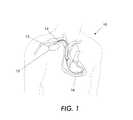
- FIG. 1is a schematic view of a medical device 12 embodying protection against electrical interference. At least one lead 14 is connected to the medical device 12 in connector block region 13 using an interface.
- the pacemaker 12includes at least one or both of pacing and sensing implanted leads represented generally as leads 14 to sense electrical signals attendant to the depolarization and repolarization of the heart 16 , and to provide pacing pulses for causing depolarization of cardiac tissue in the vicinity of the distal ends thereof.
- FIG. 2more particularly illustrates the circuit that is used conventionally to protect from electromagnetic interference.
- protection circuitry 150is provided using a diode array component 130 .
- the diode arrayconsists of five zener diode triggered silicon controlled rectifiers (SCRs) with anti-parallel diodes arranged in an array with one common connection. This allows for a small component size despite the large currents that may be carried through the device during defibrillation, e.g., 10 amps.
- the SCRs 120 - 124turn on and limit the voltage across the device when excessive voltage and current surges occur.
- the zener diode triggered SCRs 120 , 121 , 123 , and 124are connected to an electrically conductive pin 125 , 126 , 128 , and 129 .
- the electrically conductive pin 125 , 126 , 128 , and 129are connected to medical device contact regions 131 , 132 , 134 , and 135 to be wire bonded to pads of a printed circuit board.
- the diode array component 130is connected to the electrically conductive pins 125 , 126 , 128 , and 129 via the die contact regions along with other electrical conductive traces of the printed circuit board.
- One aspect of the present inventionis a photonic adapter to provide an operational electrical interface between a medical assist device and a photonic catheter.
- the photonic adapterincludes a housing; an electrical interface to provide an operative connection between the photonic adapter and the medical assist device; and a photonic transducer to convert electrical energy from the medical assist device to optical energy, the optical energy being utilized by the photonic catheter.
- the photonic adapterto provide an operational transmitter/receiver interface between a medical assist device and a photonic catheter.
- the photonic adapterincludes a housing; a transmitter/receiver interface to provide an operative communication connection between the adapter and the medical assist device; and a transducer to convert information from the medical assist device into optical energy.
- a third aspect of the present inventionis an electromagnetic radiation immune medical assist system.
- the electromagnetic radiation immune medical assist systemincludes a medical assist device; a photonic lead having a proximal end and a distal end; and an adapter to operatively connect the medical assist device with the photonic catheter.
- the adapterincludes a housing, an interface to provide an operative communication connection between the adapter and the medical assist device, and a transducer to convert information from the medical assist device into optical energy.
- a fourth aspect of the present inventionis an adaptive bridge for providing an interface between a photonic adapter and a medical assist device.
- the adaptive bridgeincludes a first interface to provide an electrical connection between the adaptive bridge and the medical assist device; a second interface to provide an electrical connection between the adaptive bridge and the photonic adapter; and a passive electrical lead to provide an electrical conduit between the first interface and the second interface.
- a fifth aspect of the present inventionis a medical assist system.
- the medical assist systemincludes a medical assist device; a photonic adapter; and an adaptive bridge for providing an interface between the photonic adapter and the medical assist device.
- FIGS. 1 and 2are illustrations of conventional techniques used to protect against electromagnetic interference
- FIG. 3is a block diagram of one embodiment of an MRI immune cardiac pacing system according to some or all of the concepts of the present invention
- FIG. 4is a block diagram of one embodiment of a photonic catheter according to some or all of the concepts of the present invention.
- FIGS. 5 through 20are schematics of various adapter transducers and corresponding distal end photonic catheter components according to some or all of the concepts of the present invention.
- FIGS. 21 and 22are detailed block diagrams of a photonic transducer according to the concepts of the present invention.
- FIG. 23is a detailed block diagram of an impedance sensing circuit in a photonic catheter according to the concepts of the present invention.
- FIG. 24is a schematic showing an adaptive bridge that provides electrical connection between a conventional medical assist device and a photonic catheter with an integral electric-optical adapter according to the concepts of the present invention.
- FIG. 25is a schematic showing an adaptive bridge that provides electrical connection between a conventional medical assist device and a combined photonic catheter and EMI shielded electrical lead system with an integral electric-optical adapter according to the concepts of the present invention.
- the term, medical assist devicerefers to any device that may enable monitoring of living tissue(s) or living system(s) wherein the monitoring may be, but not limited to an EKG signal, an ECG signal, a glucose level, hormone level, or cholesterol level.
- the medical assist devicemay also enable stimulus intervention to provide assistance to living tissue(s) or living system(s) so that the stimulus causes the selected body tissue or system to function as desired.
- the stimulusmay be, but not limited to, a cardiac stimulating substance or electrical pulse, a blood thinning substance, insulin, estrogen, progesterone, or testosterone.
- the medical assist devicemay be implanted in a body cavity of a living organism, either.
- medical assist devicemay be located external to the living organism.
- cardiac pacerssuch as pacemakers
- IPGsimplantable pulse generators
- CDPscardioverter/defibrillator/pacemakers
- cardiac monitoring systemsinsulin pump controllers, brain monitoring systems, etc.
- FIG. 3illustrates an MRI-compatible cardiac pacing system according to one embodiment of the present invention.
- the cardiac pacing systemincludes a cardiac pacer 1 that is designed to be located outside the body or implanted inside the body.
- the cardiac pacing systemalso includes an adapter 2 , which can also be located outside the body or implanted inside the body, and is connected to the cardiac pacer by means of a first connector interface 3 . Electrical pulses generated by the cardiac pacer are fed to the adapter 2 through the first connector interface 3 .
- the adapter 2can be connected to a proximal end 6 of a photonic catheter 7 by means of second connector interface (not shown).
- the adapter 2can be integral with the photonic catheter 7 so that a second connector interface is not required. Moreover, the adapter 2 can be connected to a proximal end of an EMI shielded electrical lead system by means of second connector interface (not shown). Lastly, the adapter 2 can be integral with the EMI shielded electrical lead system so that the second connector interface is not required.
- the adapter enclosure 2houses a self-contained electrical power source 4 and an electro-optical (photonic) transducer 5 .
- the power source 4which may include one or more batteries, serves as a power booster for the cardiac pacing system.
- the electro-optical (photonic) transducer 5receives electrical pulses from the cardiac pacer 1 , and converts them into optical signals.
- the optical signalsare directed to the proximal end 6 of photonic catheter 7 .
- the optical signalsare transmitted through the optical conduction pathway 8 to the distal end 9 of the photonic catheter 7 , and used to stimulate the heart 16 .
- the electro-optical (photonic) transducer 5includes a control circuit 102 that is electrically connected to the cardiac pacer through electrical connection 108 .
- the control circuit 102is further connected to a light source 106 , preferably a laser source, and an optical sensor 104 .
- the light source 106 and optical sensor 104interact with a waveguide 110 , which is part of a photonic catheter, in any of the manners described below with respect to FIGS. 5-20.
- the control circuit 102 of FIG. 21converts the electrical pacing signals to pulses of light or optical energy that represent the information conveyed in the original electrical pacing signals.
- the pacing informationcan be conveyed to the distal end of the photonic catheter using pulsewidth modulation of the light source 106 by the control circuit 102 controlling the “ON” and “OFF” time of the light source 106 .
- the pacing informationcan be conveyed to the distal end of the photonic catheter using pulse intensity modulation of the light source 106 by the control circuit 102 controlling the amount of power that the light source 106 receives from the power source 4 , thereby controlling the intensity of the light pulse created by light source 106 .
- Optical sensor 104receives biosensor feedback from the distal end of the photonic catheter, via encoded light pulses.
- the optical sensor 104converts the encoded light pulses to electrical energy, which in turn is converted into electrical signals by the control circuit 102 so that the measured biofeedback can be properly conveyed back to the cardiac pacing device.
- the adapter enclosure 2also includes a shielding to shield the adapter and any circuits therein from electromagnetic interference.
- the shieldmay be a metallic sheath, a carbon composite sheath, or a polymer composite sheath to shield the adapter and any circuits therein from electromagnetic interference.
- the shieldmay be further covered with a biocompatible material wherein the biocompatible material may be a non-permeable diffusion resistant biocompatible material if the adapter is to be implanted.
- FIG. 4illustrates in more detail the MRI compatible cardiac pacing system described in FIG. 3 .
- the cardiac paceris readily implemented to operate in a fixed-rate (VOO) mode.
- the cardiac pacing systemincludes an adapter 41 , which is connected to the proximal end 42 of photonic catheter 43 .
- a distal end 44 of photonic catheter 43mounts a bipolar endocardial (or pericardial) electrode pair 45 that includes a second enclosure 46 and a third enclosure 47 separated by a short insulative spacer 48 .
- Other electrode configurationscould also be used.
- the photonic catheter 43includes an optical transmission pathway 49 surrounded by a protective outer covering 50 .
- the optical transmission pathway 49may be constructed with one or more fiber transmission elements that are conventionally made from glass or plastic fiber material, e.g., a fiber optic bundle.
- the protective outer covering 50should be made from a biocompatible material, such as, but not limited to, silicone rubber, polyurethane, polyethylene, or other biocompatible polymer having the required mechanical and physiological properties.
- the protective outer covering 50is thus a biocompatible covering.
- the biocompatible covering 50is preferably a very thin-walled elongated sleeve or jacket having an outside diameter on the order of one to five millimeters. This will render the photonic catheter 43 sufficiently slender to facilitate insertion thereof through a large vein, such as the external jugular vein.
- the proximal end 42 of photonic catheter 43is mounted on the adapter enclosure 41 using an appropriate connection.
- the optical conduction pathway 49may extend into the adapter enclosure 41 for a short distance, where it terminates in adjacent relationship with the electro-optical (photonic) transducer in order to receive light energy therefrom.
- photonic catheter 43Light emitted by the electro-optical (photonic) transducer is directed into the proximal end 42 of photonic catheter 43 , and transmitted through the optical conduction pathway 49 to the second enclosure 46 . Since the photonic catheter 43 is designed for optical transmission, it cannot develop magnetically induced or RF-induced electrical currents, as is the case with the metallic leads of conventional cardiac pacer catheters.
- the second enclosure 46houses an opto-electrical transducer 51 , which converts light energy received from the distal end of photonic catheter 43 into electrical energy.
- the electrical output side 52 of the opto-electrical transducer 51delivers electrical pulses that drive the cardiac pacer's electrode pair 45 .
- the second enclosure 46is a hermetically sealed casing made from a non-magnetic metal, such as titanium, a titanium-containing alloy, platinum, a platinum-containing alloy, or any other suitable metal, including copper plated with a protective and compatible coating of the foregoing materials. Plated copper is especially suitable for the second enclosure 46 because it has a magnetic susceptibility approaching that of the human body, and will therefore minimize MRI image degradation. Note that the magnetic susceptibility of human body tissue is very low, and is sometimes diamagnetic and sometimes paramagnetic.
- the second enclosure 46can be formed from an electrically conductive non-metal that preferably also has a very low magnetic susceptibility akin to that of the human body. Non-metals that best approach this condition include conductive composite carbon, and conductive polymers comprising silicone, polyethylene, or polyurethane.
- the second enclosure 46includes an outer wall 53 (in a preferred embodiment, the outer wall 53 is cylindrical, but any suitable shape may be utilized) and a pair of disk-shaped end walls 54 and 55 .
- the end wall 54is mounted to the distal end 44 of the photonic catheter 43 using an appropriate sealed connection that prevent body fluids from contacting the optical conduction pathway 49 and from entering the second enclosure 46 .
- the photonic catheter 43may feed directly from the adapter's enclosure 41 to the second enclosure 46 , another arrangement would be to provide an optical coupling (not shown) at an intermediate location on the photonic catheter.
- the optoelectrical transducer 51needs to be implemented as a miniaturized circuit. However, such components are conventionally available from commercial electronic manufacturers. Note that the opto-electrical transducer 51 also needs to be adequately supported within the second enclosure 46 . To that end, the second enclosure 46 can be filled with a support matrix material 56 that may be the same material used to form the photonic catheter's biocompatible covering.
- the second enclosure 46represents part of an electrode pair 45 that delivers the electrical output of the pacemaker to a patient's heart.
- the electrode pair 45is a tip/ring system and the second enclosure 46 is used as an endocardial (or pericardial) ring electrode thereof.
- a positive output lead 57 extending from the electrical output side 52 of the opto-electrical transducer 51is electrically connected to the cylindrical wall 53 of the second enclosure 46 , as by soldering, welding or the like.
- a negative output lead 58 extending from the electrical output side 52 of the opto-electrical transducer 51is fed out of the second enclosure 46 and connected to a third enclosure 47 , which functions as an endocardial tip electrode of the electric pair 45 .
- the third enclosure 47can be constructed from the same non-metallic material, or non-metal material, used to form the second enclosure 46 . Since it is adapted to be inserted in a patient's heart as an endocardial tip electrode, the third enclosure 47 has a generally bullet shaped tip 60 extending from a tubular base end 59 .
- the base end 59preferably has an outside diameter that substantially matches the diameter of the second enclosure 46 and the photonic catheter 43 .
- the base end 59 of the third enclosure 47is open insofar as the third enclosure 47 does not house any critical components. Indeed, it mounts only the negative lead 58 that is electrically connected to the third enclosure's base end 59 , as by soldering, welding, or the like.
- spacer 48preferably fills the interior of the second enclosure 46 so that there are no voids and so that the negative lead 58 is fully captured therein.
- the adapter of the present inventionprovides an operational interface between a conventional medical assist device, such as a cardiac pacer, and an implanted photonic catheter.
- the photonic cathetercan be used in a MRI environment to sense the biological conditions of particular tissue regions of a patient or to stimulate particular tissue regions of the patient.
- the components of the adaptermust be such as to correspond to the components of the photonic catheter to enable proper functionality. Examples of corresponding photonic catheter component and adapter component sets are illustrated in FIGS. 5 through 20.
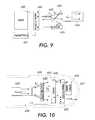
- the adapterincludes a power supply 595 and logic and control unit 597 to enable emitter 598 to transmit radiation, preferably optical radiation at wavelength ⁇ 1 through beam splitter 900 into waveguide 601 .
- This radiationexits the waveguide 601 at the distal end of the photonic catheter and passes through beam splitter 606 to sensor 607 that converts the radiation to electrical energy.
- the electrical energyis used to directly power functions at the distal end of photonic catheter 602 , such as stimulation of internal body tissues and organs (e.g. pacing of cardiac tissues) through electrodes 604 and 603 .
- the electrical energyis also used to power logic and control unit 608 or is stored in energy storage device 609 (e.g. a capacitor) for later use.
- Adapter located elementsare electrically connected through electrical conductors.
- Distally located sensor 607 , logic and control unit 608 , energy storage device 609 , and electrodes ( 604 , 603 )are electrically connected through electrically conductive elements.
- a second emitter 600 in the adaptertransmits radiation at wavelength ⁇ 2 ( ⁇ 2 ⁇ X 1 ) through beam splitter 901 , off beam splitter 900 , into waveguide 601 of the photonic catheter, to beam splitter 606 and optical attenuator 605 that is mounted on a mirror.
- the optical attenuator 605is preferably made from materials such as liquid crystals whose optical transmission density is modulated by applied electrical voltage.
- the distally located logic and control unit 608 and optical attenuator 605are powered either directly by excitation radiation or from energy stored in energy storage element 609 .
- the photonic cathetercan also be used with electrodes 603 and 604 to capture physiological electrical signals or other measurements made by biosensors and converted to electrical signals from the patient and direct these electrical signals to logical and control unit 608 that uses electrical energy to modulate the optical transmission density of optical attenuator 605 .
- Attenuated optical signalsoriginally emanating from emitter 600 , are encoded with the electrical signals received by electrodes 603 and 604 by passing through the optical attenuator 605 , reflect off mirror, travel back through the optical attenuator 605 , reflect off beam splitter 606 and into waveguide 601 to beam splitters 900 and 901 in the adapter to sensor 599 that converts the encoded optical signal to an encoded electrical signal.
- Output from sensor 599is sent to logic and control unit 597 .
- This outputis either utilized by logic and control unit 597 to control the radiation from emitter 598 , which is typically at a high energy level and is used to stimulate distally located tissues and organs, or is relayed to transmitter 596 which relays this sensory information to external sources.
- transmitter 596may also be an electrical interface to a medical assist device.
- FIG. 7is similar to the embodiment illustrated in FIGS. 5 and 6, with the exception that the optical attenuator 612 is mounted over the surface of the distally located sensor 613 to take advantage of the first surface reflectance of this sensor. Radiation emitted by waveguide 610 passes through optical attenuator 612 to sensor 613 that converts the radiation to electrical energy as previously described. Radiation emitted by waveguide 610 passes through optical attenuator 612 and reflects off the front surface of sensor 613 . This reflected energy is collected by coupling lens 611 that directs the energy into waveguide 610 to a sensor within the adapter (not shown).
- FIG. 8The embodiment illustrated in FIG. 8 is similar to the embodiment illustrated in FIGS. 5 and 6, with the exception that a variable reflectance optical reflector 616 is mounted over the surface of the distally located sensor 617 . Radiation emitted by waveguide 619 passes through optical reflector 616 to sensor 617 that converts the radiation to electrical energy as previously described. Radiation emitted by waveguide 619 is reflected off optical reflector 616 and is collected by coupling lens 618 that directs the energy into waveguide 619 . Preferably, the variable reflectance optical reflector 616 would be transparent to excitation radiation.
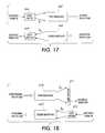
- the adapterincludes a power supply 620 and logic and control unit 622 to enable emitter 623 to transmit radiation, preferably optical radiation at wavelength ⁇ 1 through beam splitter 624 into waveguide 626 of photonic catheter.
- This radiationexits the waveguide and passes through an on-axis variable intensity optical emitter 631 to sensor 632 that converts the radiation to electrical energy.
- the electrical energyis used to directly power functions at the distal end of photonic catheter 635 , such as stimulation of internal body tissues and organs (e.g. pacing of cardiac tissues) through electrodes 627 and 628 ; to power logic and control unit 633 ; or to store in energy storage device 634 (e.g. a capacitor) for later use.
- Adapter located elementsare electrically connected through conductors.
- Distally located sensor, logic and control unit, energy storage device, and electrodesare electrically connected through conductive elements.
- Logic and control unit 633receives sensor input from electrodes 627 and 628 and delivers an electrical potential to variable intensity optical emitter 631 causing it to emit optical radiation at wavelength ⁇ 2 ( ⁇ 2 ⁇ 1 ) which is collected by coupling lens 630 and directed into waveguide 629 , to beam splitter 624 and sensor 625 .
- the distally located logic and control unit 633 and optical attenuator 631are powered either directly by excitation radiation or from energy stored in energy storage element 634 .
- the photonic cathetercan also be used with electrodes 627 and 628 to capture electrical signals from the patient and direct the captured electrical signals to logical and control unit 633 that uses electrical energy to modulate the variable intensity optical emitter 631 .
- Optical signals, emanating from variable intensity optical emitter 631are encoded with the electrical signals received by electrodes 627 and 628 and travel into waveguide 629 to beam splitter 624 to sensor 625 that converts the encoded optical signal to an encoded electrical signal. Output from sensor 625 is sent to logic and control unit 622 .
- This outputis either utilized by logic and control unit 622 to control the radiation from emitter 623 , which is typically at a high energy level and is used to stimulate distally located tissues and organs, or is relayed to transmitter 621 which relays this sensory information to external sources. It is noted that transmitter 621 may also be an electrical interface to a medical assist device.
- FIGS. 11 and 12The embodiment illustrated in FIGS. 11 and 12 is similar to the embodiment illustrated in FIGS. 9 and 10, with the exception that the variable intensity optical emitter 646 is located off-axis.
- Power supply 636 and logic and control unit 638enable emitter 639 to transmit radiation, preferably optical radiation at wavelength ⁇ 1 through beam splitter 910 into waveguide 641 . This radiation exits the waveguide 643 and passes through beam splitter 645 to sensor 647 that converts the radiation to electrical energy.
- the electrical energyis used to directly power functions at the distal end of lead 642 , such as stimulation of internal body tissues and organs (e.g. pacing of cardiac tissues) through electrodes 650 and 644 ; power logic and control unit 648 ; or to be stored in energy storage device 649 (e.g. a capacitor) for later use.
- energy storage device 649e.g. a capacitor
- Adapter located elementsare electrically connected through conductors.
- Distally located sensor 647 , logic and control unit 648 , energy storage device 649 , and electrodes 650 and 644are electrically connected through conductive elements.
- Variable intensity emitter 646transmits radiation at wavelength ⁇ 2 ( ⁇ 2 ⁇ 1 ) off beam splitter 645 into waveguide 643 and off beam splitter 910 to sensor 640 .
- the variable intensity emitter 646emits optical radiation when excited by an electrical potential, and is mounted upon a mirror to direct a greater percentage of emissions into waveguide 643 .
- a preferred application of the embodiment illustrated in FIGS. 11 and 12uses electrodes 650 and 644 to capture electrical signals and direct them to logical and control unit 648 which delivers electrical energy to emitter 646 to emit optical radiation that is encoded with the electrical signals received by electrodes 650 and 644 .
- the encoded optical signalsare directed to beam splitter 645 and into waveguide 643 to sensor 640 that converts the encoded optical signal to an encoded electrical signal. Output from sensor 640 is sent to logic and control unit 638 .
- This outputis either utilized by logic and control unit 638 to control the radiation from emitter 639 , which is typically at a high energy level (typically higher than radiation from emitter 646 ) and is used to stimulate distally located tissues and organs, or is relayed to transmitter 637 that relays this sensory information to external sources. It is noted that transmitter 637 may also be an electrical interface to a medical assist device.
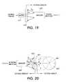
- radiation emitter 651located in the adapter, transmits radiation, preferably optical radiation at wavelength ⁇ 1 through beam splitter 652 into waveguide 655 of the photonic catheter. This radiation exits waveguide 656 at exit angle ⁇ and impinges upon sensor 657 that converts the radiation to electrical energy.
- the electrical energyis used as previously described.
- a second emitter 658 located on or within sensor 657transmits radiation at wavelength ⁇ 2 ( ⁇ 2 ⁇ 1 ) at cone angle ⁇ into waveguide 656 to beam splitter 652 .
- the small size ‘d’ of emitter 658 relative to the larger size ‘D’ of sensor 658 and narrow radiation exit angle ⁇ and emission angle ⁇enable effective coupling of radiation from emitter 651 into sensor 657 and radiation from emitter 658 into waveguide 656 .
- Optional coupling lens 653collects and directs radiation to sensor 654 .
- the distally located light sourcemay be a solid-state laser, light emitting diode, or other source of optical energy.
- radiation emitter 659located in the adapter, transmits radiation, preferably optical radiation at wavelength ⁇ 1 and exit angle ⁇ 1 through optional coupling lens 661 into waveguide 662 .
- This radiationexits waveguide 663 at exit angle ⁇ 1 and impinges upon sensor 664 that converts the radiation into electrical energy.
- the electrical energyis used as previously described.
- a second emitter 665 located on or within sensor 664transmits radiation at wavelength ⁇ 2 at cone angle ⁇ 2 into waveguide 663 .
- This radiationexits waveguide 662 at exit angle ⁇ 2 onto sensor 660 .
- wavelength ⁇ 2 ⁇ 1so that optical reflections from coupling lens 661 or waveguide 662 do not interfere with radiation incident upon detector 660 .
- the small sizes ‘d’ of emitters 659 and 665 relative to the larger sizes ‘D’ of sensors 660 and 664combined with narrow radiation exit angles ⁇ 1 and ⁇ 2 , and ⁇ 1 and ⁇ 2 , enable effective coupling of radiation into waveguide ( 662 , 663 ), and sensors 660 and 664 .
- radiation emitter 666located in the adapter, transmits radiation, preferably optical radiation at wavelength ⁇ 1 into waveguide 667 .
- This radiationexits waveguide 670 and impinges upon sensor 671 that converts the radiation into electrical energy.
- the electrical energyis used as previously described.
- a second distally located emitter 672transmits radiation at wavelength ⁇ 2 into waveguide 673 . This radiation exits waveguide 668 onto proximally located sensor 669 . Wavelength ⁇ 2 may or may not be equal to wavelength ⁇ 1 .
- Light sources 666 and 672include a solid-state laser or light emitting diode. Waveguides ( 667 , 670 ) and ( 668 , 673 ) are preferably included in the same lead assembly.
- a sensor 678located in the adapter, transparent to certain wavelengths of optical radiation is used.
- Radiation emitter 677located in the adapter, transmits radiation, preferably optical radiation at wavelength ⁇ 1 through sensor 678 that is transparent to wavelength ⁇ 1 into waveguide 679 and exiting at exit angle ⁇ to sensor 682 that converts the radiation to electrical energy.
- the electrical energyis used as previously described.
- a second emitter 681 located on or within sensor 682transmits radiation at wavelength ⁇ 2 ( ⁇ 2 ⁇ 1 ) at cone angle ⁇ into waveguide 680 to proximally located sensor 678 where it is absorbed and converted into electrical energy.
- the small size ‘d’ of emitter 681 relative to the larger size ‘D’ of sensor 682 and narrow radiation exit angle ⁇ and emission angle ⁇enable effective coupling of radiation from emitter 677 into sensor 682 and radiation from emitter 681 into waveguide 680 .
- the photonic lead and corresponding photonic adapter of the present inventionelectrically “look like” a conventional wire lead to a conventional pacemaker device.
- the photonic lead and corresponding photonic adapter of the present inventionshould be designed so that it is difficult for a conventional pacemaker device to tell, electronically, that the conventional pacemaker is connected to anything other than a conventional electrical wire lead.
- the photonic adapter of the present inventionincludes a predetermined number of resistors, inductors, and capacitors (preferably located within the photonic transducer) that are either preset or adjusted in a manner so that the combination of the photonic adapter and photonic lead mimic the resistance, inductance, and capacitance of a conventional wire lead that would have normally been attached to the pulse generator of a cardiac pacing device.
- a pulse generator in a cardiac pacerdrives an impedance load 118 , within the photonic transducer 5 , through electrical connection 108 .
- the impedance load 118includes a resistive load 116 , preferably a 1K ⁇ resistor, which is connected in parallel to a capacitive load 114 .
- the resistive load 116is further connected in series with an inductive load 112 .
- the impedance load 118is connected to control circuit 102 .
- the control circuit 102is further connected to light source 106 , preferably a laser source, and optical sensor 104 .
- the light source 106 and optical sensor 104interact with a waveguide 110 , which is part of a photonic catheter, in any of the manners described above with respect to FIGS. 5-20.
- the control circuit 102 of FIG. 22converts the electrical pacing signals to pulses of light or optical energy that represent the information conveyed in the original electrical pacing signals.
- the pacing informationcan be conveyed to the distal end of the photonic catheter using pulsewidth modulation of the light source 106 by the control circuit 102 controlling the “ON” and “OFF” time of the light source 106 .
- the pacing informationcan be conveyed to the distal end of the photonic catheter using pulse intensity modulation of the light source 106 by the control circuit 102 controlling the amount of power that the light source 106 receives from the power source 4 , thereby controlling the intensity of the light pulse created by light source 106 .
- Optical sensor 104receives biosensor feedback from the distal end of the photonic catheter, via encoded light pulses.
- the optical sensor 104converts the encoded light pulses to electrical energy, which in turn is converted into electrical signals by the control circuit 102 so that the measured biofeedback can be properly conveyed back to the cardiac pacing device.
- resistive load 116The combination of the resistive load 116 , capacitive load 114 , and inductive load 112 mimic a conventional electrical wire lead's resistance, capacitance, and inductance (overall impedance).
- variable delay 120is introduced into the photonic adapter to delay the transmission of the pacing signal from the pulse generator to the heart and the transmission of the feedback signal from the heart to the pulse generator.
- the variable delay 120provides proper synchronization of the flow of information to and from the pulse generator.
- pacemaker leadsare tested for continuity and proper interface with myocardium at installation and periodically after the installation procedure by measuring the impedance of the lead-myocardium system. This impedance will vary with time and physiological changes in the patient.
- the distal end of a photonic catheter 200includes an impedance measuring circuit 214 .
- the impedance measuring circuit 214is connected across a ring electrode 210 and a tip electrode 212 .
- the impedance measuring circuit 214sends small test signals to the electrodes 210 and 212 and measures the resistance of the circuit to determine the impedance of the lead-myocardium system.
- the measured impedanceis fed to a control circuit 208 , which is retained by the control circuit 208 to be used to modify the pacing energy applied to the heart in accordance with the measured impedance to ensure the proper amount of energy is delivered to the electrodes to effectuate proper pacing.
- the measuring of the impedance of the lead-myocardium system and proper compensationtherefore can be achieved by any conventional method.
- Examples of such conventional methodsare disclosed in U.S. Pat. No. 5,775,742, to Schuelke et al.; U.S. Pat. No. 5.897,577 to Cinbis et al.; and U.S. Pat. No. 6,317,633 to Jorgenson et al.
- the entire content of these U.S. Patents(U.S. Pat. No. 5,775,742; U.S. Pat. No. 5.897,577; and U.S. Pat. No. 6,317,633) is hereby incorporated by reference.
- the distal end of the photonic leadis provided with the ability to measure impedance (impedance measuring circuit 214 ) at the electrode-myocardium interface, convert this into an encoded optical signal (sensor & light source 204 ), and transmit the encoded optical signal through waveguide 202 to the photonic adapter any change in impedance that takes place in a format that the pulse generator of the cardiac pacer will recognize as an accurate measure of actual change in interfacial impedance.
- the cardiac pacercan then respond using any conventional compensation method, such as those described above, to determine whether an adjustment in pacing pulse characteristics is required to ensure proper pacing.
- the photonic adapterhas the additional capability in the control circuit of the photonic transducer to convert this change in electrical pacing pulse from the pulse generator into an equivalent change in pacing pulse delivered to the heart at the distal end of the photonic lead.
- an enclosureprovides physical securing and sealing to an outer casing of a medical assist device with which it electrically interfaces.
- the photonic medical adapter device of the present inventionmay be manufactured with a single generic design, irrespective of its use with a wide variety of conventional, off-the-shelf medical assist devices that may have a variety of physical configurations and electrical connections.
- the photonic medical assist device adapter of the present inventionis an adapter to permit conventional electrical cardiac pacing systems to function in an MRI environment with the use of photonic technology previously described above
- the photonic adapter devicemay have a single non-varying design, irrespective of its use in conjunction with a variety of electrical cardiac pacing products sold by a variety of manufacturers.
- the present inventioncontemplates an adaptive bridge or adaptive interface, which acts as a passive electrical conduit between the conventional electrical cardiac pacing systems and the photonic adapter device described above.
- a product-specific adaptive bridge or adaptive interface moduleprovides passive electrical connection between a photonic adapter device, according to the concepts of the present invention, and the conventional cardiac pacer.
- the product-specific adaptive bridge or adaptive interface moduleprovides for exact fitment, sealing, and bonding; on one aspect to the cardiac pacer and on the other aspect, to the photonic adapter device, according to the concepts of the present invention.
- FIG. 24is a schematic of one embodiment, in which a generic photonic adapter device, according to the concepts of the present invention, provides all of the electronic, optical, control, and power functions, as well as providing an EMI-shielded and biologically sealed and compatible enclosure.
- a conventional electrical pacemaker 690is connected to a generic photonic adapter device 692 , such as the photonic adapter devices illustrated in FIGS. 3 and 4, by way of product specific adaptive bridge or interface module 694 .
- the photonic adapter device 692communicates with the heart optically, in a manner as disclosed above, through photonic catheter 696 .
- the product specific adaptive bridge or interface module 694is connected electrically with the photonic adapter 692 by way of electrical contacts 704 .
- the product specific adaptive bridge or interface module 694 and the photonic adapter 692are mechanically attached and biologically sealed at interface 720 by conventional means. These connections are preferably made during the last stages of device manufacture.
- the product specific adaptive bridge or interface module 694is further connected electrically to the conventional pacemaker 690 by way of electrical contacts 698 that communicate with electrical receptacle 700 . These contacts 698 are specifically designed to match the specific model of the conventional pacemaker 690 that is being installed. Dashed lines 702 indicate the relationship between the product specific adaptive bridge or interface module 694 and the conventional pacemaker product 690 as mechanical assembly is performed, creating an interface that provides a mechanical attachment and biological seal.
- the mechanical geometry of the product specific adaptive bridge or interface module 694is designed to exactly match the external geometry of the specific model of pacemaker 690 it is being used with and permits mechanical attachment and biological sealing at the interface by conventional means.
- the connections and sealingmay be made during the last stages of overall device manufacture, or alternatively may be made at any time prior to implantation.
- Electrical conductors 706establish internal electrical connection between contacts 700 and contacts 704 . Since the enclosures of the conventional pacemaker 690 , the product specific adaptive bridge or interface module 694 , and the photonic adapter 692 are individually shielded against electromagnetic interference and are in intimate contact, the overall assembly comprising elements 690 , 692 , and 694 will be unaffected by electromagnetic interference.
- the photonic adapter device 692provides for bi-directional opto-electronic conversion of both sensory signals and pacing pulses in a manner that provides for exact replication of pacing pulses at the distal end of photonic catheter 696 and also provides for exact replication of sensory signals within the conventional pacemaker 690 .
- the overall assemblycomprising elements 690 , 692 , and 694 will provide the same functionality as would a photonic pacemaker system, but without the need to create a new product design.
- the use of the photonic adapter of the present invention in conjunction with the product specific adaptive bridge or interface module 694provides for a simple approach to provide photonic MRI safety and MRI compatibility to a wide range of commercially available conventional pacemaker models.
- product specific adaptive bridge or interface module 694 of FIG. 24may also include the impedance load, described above, in lieu of placement of the impedance load in the photonic adapter so as to mimic the impedance of a conventional electrical lead system.
- FIG. 25A further embodiment of the present invention is shown in FIG. 25 .
- a conventional electrical implantable cardioverter defibrillator (ICD) 708is designed to carry out the multiple functions of sensing the heart, pacing the heart upon demand, and if necessary, defibrillating the heart with one or more electrical pulses that may be as high as 800 volts and having as much as 10 joules of energy or more.
- the photonic technology utilized in the photonic adapter of the present inventionis well suited for conventional sensing and cardiac pacing functions, the energy level involved in defibrillation is far higher and would be difficult to realize with photonic technology.
- ICD 708is physically affixed to a product specific adaptive bridge or interface module 694 and thence to a generic photonic adapter 692 in a manner identical to that described with respect to FIG. 24 .
- electrical connection between ICD 708 and the product specific adaptive bridge or interface module 694is made from multiple outputs 700 , through multiple connectors 698 , multiple electrical conductors 706 , and multiple connectors 704 .
- the circuitry in the photonic adapter 692provides for a direct connection between outputs from ICD 708 to electrical leads 710 .
- the electrical leads 710having the material and construction described in above-referenced co-pending U.S. patent application Ser. No. 10/077,842.
- This embodimentalso provides for multi-chamber photonic pacing by providing bi-directional opto-electronic conversion between multiple multi-chamber sensing and pacing outputs 700 on ICD 708 and multiple photonic catheters 696 that may be placed at multiple locations on the heart in order to effect properly synchronized multi-chamber pacing of the heart.
- product specific adaptive bridge or interface module 694 of FIG. 25may also include the impedance load, described above, in lieu of placement of the impedance load in the photonic adapter so as to mimic the impedance of a conventional electrical lead system.
- FIGS. 24 and 25may be extended to all manner of commercially available cardiac assist devices and to any other electronic based implantable medical devices that may be rendered safe and effective in an MRI environment by implementation of a photonic catheter for one or more of its sensing or stimulation functions.
- a medical assist device adaptersuch as cardiac adapter
- the adaptercomprises a housing, a shielding formed around the housing to shield the housing and any devices therein from electromagnetic interference; and interfaces to connect the adapter to a cardiac pacer and the adapter to implanted leads that correspond to a predetermined tissue region of the body.
- the housingmay also include a power supply for providing electrical power to an electro-optical transducer, controller and other devices also residing in the housing.
- the adaptermay receive electrical pulses from the cardiac pacer or radio frequency signals if a transmitter/receiver is used.
- the electro-optical transducerconverts the information from the cardiac pacer into optical signals, which are fed to one or more photonic leads and reconverted to electrical signals by an opto-electrical transducer located at the distal end of the photonic catheter to stimulate the tissue region, such as a heart.
- the opto-electrical transduceralso converts optical signals indicative of the functioning of the tissue region, such as a heart, into electric signals, which are used to control the operation of the medical assist device.
- the housingalso includes a controller, which processes the feedback signals indicative of the functioning of the tissue region, and generates corresponding signals that are used as feedback for controlling the operation of the medical assist device.
- the photonic catheter described abovemay be used for transmission of a signal to and from a body tissue of a vertebrate.
- the fiber optic bundlehas a surface of non-immunogenic, physiologically compatible material and is capable of being permanently implanted in a body cavity or subcutaneously.
- the fiber optic bundlehas a distal end for implantation at or adjacent to the body tissue and a proximal end.
- the proximal endis adapted to be coupled to and direct an optical signal source, and the distal end is adapted to be coupled to an optical stimulator.
- the fiber optic bundledelivers an optical signal intended to cause an optical stimulator coupled to the distal end to deliver an excitatory stimulus to a selected body tissue, such as a nervous system tissue region; e.g., spinal cord or brain.
- the stimuluscauses the selected body tissue to function as desired.
- the photonic catheterfurther includes a photoresponsive device for converting the light transmitted by the fiber optic bundle into electrical energy and for sensing variations in the light energy to produce control signals.
- a charge-accumulating devicereceives and stores the electrical energy produced by the photoresponsive device.
- a discharge control deviceresponsive to the control signals, directs the stored electrical energy from the charge-accumulating device to a cardiac assist device associated with a heart.
- the photoresponsive devicemay include a charge transfer control circuit and a photodiode.
- the charge transfer control circuitcontrols a discharging of a photodiode capacitance in two separate discharge periods during an integration period of the photodiode such that a first discharge period of the photodiode capacitance provides the sensing of variations in the light energy to produce control signals and a second discharge period of the photodiode capacitance provides the converting the light transmitted by the photonic lead system into electrical energy.
- the first discharge periodcan be a shorter time duration that the time duration of the second discharge period.
- a control signal sensing circuitis connected to the photodiode, and during the second discharge period, the charge-accumulating device is connected to the photodiode.
- the charge-accumulating devicemay be a capacitor or a rechargeable battery.
- the photonic cathetercan also transmit between the primary device housing and the cardiac assist device, both power and control signals in the form of light.
- a photoresponsive deviceconverts the light transmitted by the photonic lead system into electrical energy and to sense variations in the light energy to produce control signals.
- a charge-accumulating devicereceives and stores the electrical energy produced by the photoresponsive device, and a discharge control device, responsive to the control signals, directs the stored electrical energy from the charge-accumulating device to the cardiac assist device associated with the heart.
- the photoresponsive devicemay include a charge transfer control circuit and a photodiode.
- the charge transfer control circuitcontrols a discharging of a photodiode capacitance in two separate discharge periods during an integration period of the photodiode such that a first discharge period of the photodiode capacitance provides the sensing of variations in the light energy to produce control signals and a second discharge period of the photodiode capacitance provides the converting the light transmitted by the photonic lead system into electrical energy.
- the first discharge periodcan be a shorter time duration that the time duration of the second discharge period.
- a control signal sensing circuitis connected to the photodiode, and during the second discharge period, the charge-accumulating device is connected to the photodiode.
- the charge-accumulating devicemay be a capacitor or a rechargeable battery.
- the physical realization of the photodiodefunctions as light-detecting elements.
- the photodiodeis first reset with a reset voltage that places an electronic charge across the capacitance associated with the diode.
- Electronic charge, produced by the photodiode when exposed to illumination,causes charge of the photodiode capacitance to dissipate in proportion to the incident illumination intensity.
- the change in photodiode capacitance chargeis collected as electrical energy and the photodiode is reset.
- Charge integration function manipulationcan be realized by changing of an integration time, T int , for the photodiode. Changing the integration time, T int , changes the start time of the charge integration period.
- Integration time, T intis the time that a control signal is not set at a reset level.
- the control signalis not at a reset value, the photodiode causes charge to be transferred or collected therefrom.
- the timing of the control signalcauses charge to be transferred or collected from the photodiode for a shorter duration of time or longer duration of time. This adjustment can be used to manage the charge in the photodiode so that the photodiode does not become saturated with charge as well as to manage the current output of the sensor.
- Another conventional way of manipulating the charge integration functionis to use a stepped or piecewise discrete-time charge integration function.
- a stepped or piecewise discrete charge integration functionBy using a stepped or piecewise discrete charge integration function, the charge in the photodiode can be further managed so that the photodiode does not become saturated with charge as well as to manage the current output of the photodiode.
Landscapes
- Health & Medical Sciences (AREA)
- Life Sciences & Earth Sciences (AREA)
- Radiology & Medical Imaging (AREA)
- Veterinary Medicine (AREA)
- Public Health (AREA)
- Engineering & Computer Science (AREA)
- Biomedical Technology (AREA)
- Nuclear Medicine, Radiotherapy & Molecular Imaging (AREA)
- General Health & Medical Sciences (AREA)
- Animal Behavior & Ethology (AREA)
- Heart & Thoracic Surgery (AREA)
- Cardiology (AREA)
- Physics & Mathematics (AREA)
- Electromagnetism (AREA)
- Electrotherapy Devices (AREA)
Abstract
Description
Claims (21)
Priority Applications (3)
| Application Number | Priority Date | Filing Date | Title |
|---|---|---|---|
| US10/132,457US6725092B2 (en) | 2002-04-25 | 2002-04-25 | Electromagnetic radiation immune medical assist device adapter |
| PCT/US2003/012994WO2003090846A2 (en) | 2002-04-25 | 2003-04-24 | Electromagnetic radiation immune medical assist device adapter |
| AU2003231769AAU2003231769A1 (en) | 2002-04-25 | 2003-04-24 | Electromagnetic radiation immune medical assist device adapter |
Applications Claiming Priority (1)
| Application Number | Priority Date | Filing Date | Title |
|---|---|---|---|
| US10/132,457US6725092B2 (en) | 2002-04-25 | 2002-04-25 | Electromagnetic radiation immune medical assist device adapter |
Publications (2)
| Publication Number | Publication Date |
|---|---|
| US20030204207A1 US20030204207A1 (en) | 2003-10-30 |
| US6725092B2true US6725092B2 (en) | 2004-04-20 |
Family
ID=29248775
Family Applications (1)
| Application Number | Title | Priority Date | Filing Date |
|---|---|---|---|
| US10/132,457Expired - Fee RelatedUS6725092B2 (en) | 2002-04-25 | 2002-04-25 | Electromagnetic radiation immune medical assist device adapter |
Country Status (3)
| Country | Link |
|---|---|
| US (1) | US6725092B2 (en) |
| AU (1) | AU2003231769A1 (en) |
| WO (1) | WO2003090846A2 (en) |
Cited By (65)
| Publication number | Priority date | Publication date | Assignee | Title |
|---|---|---|---|---|
| US20050070972A1 (en)* | 2003-09-26 | 2005-03-31 | Wahlstrand Carl D. | Energy shunt for producing an MRI-safe implantable medical device |
| US20050090886A1 (en)* | 2001-02-20 | 2005-04-28 | Biophan Technologies, Inc. | Medical device with an electrically conductive anti-antenna geometrical shaped member |
| US20050113876A1 (en)* | 2003-04-02 | 2005-05-26 | Biophan Technologies, Inc. | Device and method for preventing magnetic-resonance imaging induced damage |
| US20050222647A1 (en)* | 2004-03-30 | 2005-10-06 | Wahlstrand Carl D | Lead electrode for use in an MRI-safe implantable medical device |
| US20050222642A1 (en)* | 2004-03-30 | 2005-10-06 | Medtronic, Inc. | Lead electrode for use in an MRI-safe implantable medical device |
| US20050222658A1 (en)* | 2004-03-30 | 2005-10-06 | Medtronic, Inc. | Lead electrode for use in an MRI-safe implantable medical device |
| US20050222659A1 (en)* | 2004-03-30 | 2005-10-06 | Medtronic, Inc. | Lead electrode for use in an MRI-safe implantable medical device |
| US20050222656A1 (en)* | 2004-03-30 | 2005-10-06 | Wahlstrand Carl D | MRI-safe implantable medical device |
| US20060178576A1 (en)* | 2005-02-04 | 2006-08-10 | Boston Scientific Scimed, Inc. | Resonator for medical device |
| US20060200218A1 (en)* | 2005-02-01 | 2006-09-07 | Wahlstrand Carl D | Extensible implantable medical lead |
| US20060247748A1 (en)* | 2005-04-29 | 2006-11-02 | Medtronic, Inc. | Lead electrode for use in an MRI-safe implantable medical device |
| US20070021814A1 (en)* | 2005-07-21 | 2007-01-25 | Cyberonics, Inc. | Safe-mode operation of an implantable medical device |
| US20070023424A1 (en)* | 2005-07-26 | 2007-02-01 | Boston Scientific Scimed, Inc. | Resonator for medical device |
| US20070049789A1 (en)* | 2005-08-29 | 2007-03-01 | Boston Scientific Scimed, Inc. | Cardiac sleeve apparatus, system and method of use |
| US20070062933A1 (en)* | 2005-08-23 | 2007-03-22 | Boston Scientific Scimed, Inc. | Resonator with adjustable capacitor for medical device |
| US20070106151A1 (en)* | 2005-11-09 | 2007-05-10 | Boston Scientific Scimed, Inc. | Resonator with adjustable capacitance for medical device |
| WO2007047966A3 (en)* | 2005-10-21 | 2007-06-21 | Surgivision Inc | Mri-safe high impedance lead systems |
| US20070244535A1 (en)* | 2006-04-18 | 2007-10-18 | Cyberonics, Inc. | Heat dissipation for a lead assembly |
| US20070255166A1 (en)* | 2006-04-26 | 2007-11-01 | Carney James K | Contactless Interconnect for Transducers |
| US20080015641A1 (en)* | 2006-07-12 | 2008-01-17 | Cyberonics, Inc. | Implantable Medical Device Charge Balance Assessment |
| US20080058913A1 (en)* | 2003-06-24 | 2008-03-06 | Biophan Technologies, Inc. | Magnetic resonance imaging interference immune device |
| US20080077190A1 (en)* | 2006-09-21 | 2008-03-27 | Cardiac Pacemakers, Inc. | Implantable Medical Device Header With Optical Interface |
| US20080079429A1 (en)* | 2003-06-24 | 2008-04-03 | Biophan Technologies, Inc. | Magnetic resonance imaging interference immune device |
| US7369898B1 (en)* | 2004-12-22 | 2008-05-06 | Pacesetter, Inc. | System and method for responding to pulsed gradient magnetic fields using an implantable medical device |
| US20080129435A1 (en)* | 2003-06-24 | 2008-06-05 | Medtronic, Inc. | Magnetic resonance imaging interference immune device |
| US20080183258A1 (en)* | 2007-01-26 | 2008-07-31 | Inman D Michael | Electrode assembly with fibers for a medical device |
| US20080186691A1 (en)* | 2006-04-28 | 2008-08-07 | Mertz John C | Implantable medical device housing reinforcement |
| US20080195186A1 (en)* | 2007-02-14 | 2008-08-14 | Bernard Li | Continuous conductive materials for electromagnetic shielding |
| US20080195187A1 (en)* | 2007-02-14 | 2008-08-14 | Bernard Li | Discontinuous conductive filler polymer-matrix composites for electromagnetic shielding |
| US20080269863A1 (en)* | 2007-04-25 | 2008-10-30 | Medtronic, Inc. | Lead or lead extension having a conductive body and conductive body contact |
| US7447533B1 (en) | 2003-09-25 | 2008-11-04 | Pacesetter, Inc. | Implantable electronic medical device having an encapsulated optical transducer |
| US20080277773A1 (en)* | 2007-05-11 | 2008-11-13 | International Business Machines Corporation | Circuit structures and methods with beol layer(s) configured to block electromagnetic interference |
| US20080306375A1 (en)* | 2007-06-07 | 2008-12-11 | Surgi-Vision, Inc. | Mri-guided medical interventional systems and methods |
| US20090112084A1 (en)* | 2007-06-07 | 2009-04-30 | Surgi-Vision, Inc. | Mri-guided medical interventional systems and methods |
| US20090118610A1 (en)* | 2005-11-29 | 2009-05-07 | Karmarkar Parag V | Mri-guided localization and/or lead placement systems, related methods, devices and computer program products |
| US20090131783A1 (en)* | 2007-11-21 | 2009-05-21 | Surgi-Vision, Inc. | Methods, systems and computer program products for positioning a guidance apparatus relative to a patient |
| US20090138058A1 (en)* | 2004-12-17 | 2009-05-28 | Cardiac Pacemakers, Inc. | Mri operation modes for implantable medical devices |
| US7561915B1 (en) | 2004-12-17 | 2009-07-14 | Cardiac Pacemakers, Inc. | MRI system having implantable device safety features |
| US20100032814A1 (en)* | 2008-08-08 | 2010-02-11 | International Business Machines Corporation | Circuit structures and methods with beol layers configured to block electromagnetic edge interference |
| US20100087892A1 (en)* | 2008-10-02 | 2010-04-08 | Stubbs Scott R | Implantable medical device responsive to mri induced capture threshold changes |
| US20100192374A1 (en)* | 2006-07-26 | 2010-08-05 | Cyberonics, Inc. | Multi-Electrode Assembly for an Implantable Medical Device |
| US20100211123A1 (en)* | 2009-02-19 | 2010-08-19 | Stubbs Scott R | Systems and methods for providing arrhythmia therapy in mri environments |
| US7844344B2 (en) | 2004-03-30 | 2010-11-30 | Medtronic, Inc. | MRI-safe implantable lead |
| US7853332B2 (en) | 2005-04-29 | 2010-12-14 | Medtronic, Inc. | Lead electrode for use in an MRI-safe implantable medical device |
| US8032228B2 (en) | 2007-12-06 | 2011-10-04 | Cardiac Pacemakers, Inc. | Method and apparatus for disconnecting the tip electrode during MRI |
| US8086321B2 (en) | 2007-12-06 | 2011-12-27 | Cardiac Pacemakers, Inc. | Selectively connecting the tip electrode during therapy for MRI shielding |
| US8160717B2 (en) | 2008-02-19 | 2012-04-17 | Cardiac Pacemakers, Inc. | Model reference identification and cancellation of magnetically-induced voltages in a gradient magnetic field |
| US8195272B2 (en) | 2007-09-24 | 2012-06-05 | MRI Interventions, Inc. | MRI-compatible patches and methods for using the same |
| US20120156933A1 (en)* | 2010-12-18 | 2012-06-21 | Kevin Kreger | Biosensor Interface Apparatus for a Mobile Communication Device |
| US8311637B2 (en) | 2008-02-11 | 2012-11-13 | Cardiac Pacemakers, Inc. | Magnetic core flux canceling of ferrites in MRI |
| US8315689B2 (en) | 2007-09-24 | 2012-11-20 | MRI Interventions, Inc. | MRI surgical systems for real-time visualizations using MRI image data and predefined data of surgical tools |
| US8380324B2 (en) | 2009-08-20 | 2013-02-19 | Boston Scientific Neuromodulation Corporation | Systems and methods for altering one or more RF-response properties of electrical stimulation systems |
| US8478428B2 (en) | 2010-04-23 | 2013-07-02 | Cyberonics, Inc. | Helical electrode for nerve stimulation |
| US8565874B2 (en) | 2009-12-08 | 2013-10-22 | Cardiac Pacemakers, Inc. | Implantable medical device with automatic tachycardia detection and control in MRI environments |
| US8868203B2 (en) | 2007-10-26 | 2014-10-21 | Cyberonics, Inc. | Dynamic lead condition detection for an implantable medical device |
| US8942798B2 (en) | 2007-10-26 | 2015-01-27 | Cyberonics, Inc. | Alternative operation mode for an implantable medical device based upon lead condition |
| US9186499B2 (en) | 2009-04-30 | 2015-11-17 | Medtronic, Inc. | Grounding of a shield within an implantable medical lead |
| US9192446B2 (en) | 2012-09-05 | 2015-11-24 | MRI Interventions, Inc. | Trajectory guide frame for MRI-guided surgeries |
| US9463317B2 (en) | 2012-04-19 | 2016-10-11 | Medtronic, Inc. | Paired medical lead bodies with braided conductive shields having different physical parameter values |
| US9731119B2 (en) | 2008-03-12 | 2017-08-15 | Medtronic, Inc. | System and method for implantable medical device lead shielding |
| US9993638B2 (en) | 2013-12-14 | 2018-06-12 | Medtronic, Inc. | Devices, systems and methods to reduce coupling of a shield and a conductor within an implantable medical lead |
| US10155111B2 (en) | 2014-07-24 | 2018-12-18 | Medtronic, Inc. | Methods of shielding implantable medical leads and implantable medical lead extensions |
| US10279171B2 (en) | 2014-07-23 | 2019-05-07 | Medtronic, Inc. | Methods of shielding implantable medical leads and implantable medical lead extensions |
| WO2020247137A1 (en) | 2019-06-06 | 2020-12-10 | Advanced Neuromodulation Systems, Inc. | Systems and methods for improved damage protection during electrostatic discharge and cardiac defibrillation, and for substantially improved stimulation interference mitigation in implantable pulse generators |
| US10905497B2 (en) | 2017-04-21 | 2021-02-02 | Clearpoint Neuro, Inc. | Surgical navigation systems |
Families Citing this family (8)
| Publication number | Priority date | Publication date | Assignee | Title |
|---|---|---|---|---|
| FR2872709B1 (en)* | 2004-07-07 | 2006-09-15 | Commissariat Energie Atomique | MULTI-SITE CARDIAC STIMULATOR WITH SECONDED ELECTRODES NETWORK |
| DE102005039183B4 (en)* | 2005-08-18 | 2008-05-29 | Siemens Ag | Device for electrical stimulation of parts of the nervous system |
| US8139948B2 (en)* | 2006-06-12 | 2012-03-20 | Acist Medical Systems, Inc. | Process and system for providing electrical energy to a shielded medical imaging suite |
| EP2121121B1 (en)* | 2007-03-07 | 2014-12-10 | Koninklijke Philips N.V. | Apparatus for applying energy within an object |
| US9079038B2 (en) | 2010-12-20 | 2015-07-14 | Biotronik Se & Co. Kg | Implantable device with elongated electrical conductor |
| US9950180B2 (en) | 2012-04-27 | 2018-04-24 | Medtronic, Inc. | Implantable device with chassis element |
| US11052260B2 (en)* | 2017-08-31 | 2021-07-06 | Synergia Medical | Implantable electrode coupled to an optoelectronic device |
| US12303191B2 (en)* | 2018-06-13 | 2025-05-20 | Intuitive Surgical Operations, Inc. | Systems and methods for powering an antenna |
Citations (259)
| Publication number | Priority date | Publication date | Assignee | Title |
|---|---|---|---|---|
| US3057356A (en) | 1960-07-22 | 1962-10-09 | Wilson Greatbatch Inc | Medical cardiac pacemaker |
| US3478746A (en) | 1965-05-12 | 1969-11-18 | Medtronic Inc | Cardiac implantable demand pacemaker |
| US3508167A (en) | 1968-06-28 | 1970-04-21 | Mennen Greatbatch Electronics | Pulse generator |
| US3669095A (en) | 1966-08-25 | 1972-06-13 | Tokyo Shibaura Electric Co | Catheter-type semi-conductor radiation detector for insertion into a human body |
| US3686958A (en) | 1971-02-22 | 1972-08-29 | Ladd Res Ind | Fiber optic pressure detector |
| US3718142A (en) | 1971-04-23 | 1973-02-27 | Medtronic Inc | Electrically shielded, gas-permeable implantable electro-medical apparatus |
| US3789667A (en) | 1972-02-14 | 1974-02-05 | Ladd Res Ind Inc | Fiber optic pressure detector |
| US3825015A (en) | 1972-12-14 | 1974-07-23 | American Optical Corp | Single catheter for atrial and ventricular stimulation |
| US4012641A (en) | 1975-12-05 | 1977-03-15 | The United States Of America As Represented By The Secretary Of The Navy | Portable pulsed signal generator |
| US4041954A (en) | 1974-05-07 | 1977-08-16 | Kabushiki Kaisha Daini Seikosha | System for detecting information in an artificial cardiac pacemaker |
| US4050004A (en) | 1970-04-29 | 1977-09-20 | Wilson Greatbatch Ltd. | Cardiac pacer including controlled voltage multiplier |
| US4071032A (en) | 1976-01-29 | 1978-01-31 | Pacesetter Systems Inc. | Implantable living tissue stimulators |
| US4091818A (en) | 1976-08-03 | 1978-05-30 | Research Corporation | Cardiac pacing apparatus with electromagnetic interference protection |
| US4200110A (en) | 1977-11-28 | 1980-04-29 | United States Of America | Fiber optic pH probe |
| US4210029A (en) | 1979-05-04 | 1980-07-01 | Lad Research Industries, Inc. | Differential fiber optic differential pressure sensor |
| US4254776A (en) | 1976-12-28 | 1981-03-10 | Agency Of Industrial Science & Technology | Apparatus for transmission of information by electrocutaneous stimuli |
| US4325382A (en) | 1980-05-15 | 1982-04-20 | Memorial Hospital For Cancer And Allied Diseases | Process and apparatus for the real time adaptive filtering of catheter pressure measurements |
| US4333053A (en) | 1979-03-13 | 1982-06-01 | Emi Limited | Imaging systems |
| US4341221A (en) | 1980-10-07 | 1982-07-27 | Medtronic, Inc. | Shielded recording electrode system |
| US4379262A (en) | 1979-08-10 | 1983-04-05 | Picker International Limited | Nuclear magnetic resonance systems |
| US4432363A (en) | 1980-01-31 | 1984-02-21 | Tokyo Shibaura Denki Kabushiki Kaisha | Apparatus for transmitting energy to a device implanted in a living body |
| US4450408A (en) | 1981-12-11 | 1984-05-22 | General Electric Company | Low loss wide band front end for NMR receiver |
| US4476870A (en) | 1982-03-30 | 1984-10-16 | The United States Of America As Represented By The Department Of Health And Human Services | Fiber optic PO.sbsb.2 probe |
| US4491768A (en) | 1981-11-04 | 1985-01-01 | Eaton Corporation | Pulse width modulation inverter with battery charger |
| US4611127A (en) | 1984-09-20 | 1986-09-09 | Telectronics N.V. | Electronic sensor for static magnetic field |
| US4677471A (en) | 1985-08-16 | 1987-06-30 | Olympus Optical Co., Ltd. | Endoscope |
| US4686964A (en) | 1982-12-07 | 1987-08-18 | Olympus Optical Co., Ltd. | Endoscope pickup means |
| US4691164A (en) | 1985-08-30 | 1987-09-01 | Kabushiki Kaisha Toshiba | Nuclear magnetic resonance transmitter and receiver system |
| US4719159A (en) | 1986-05-19 | 1988-01-12 | Eastman Kodak Company | Sealed lithium battery |
| US4727874A (en) | 1984-09-10 | 1988-03-01 | C. R. Bard, Inc. | Electrosurgical generator with high-frequency pulse width modulated feedback power control |
| US4763075A (en) | 1984-08-20 | 1988-08-09 | Siemens Aktiengesellschaft | Electro-optical isolator for magnetic resonance tomography |
| US4784461A (en) | 1986-11-04 | 1988-11-15 | Northern Telecom Limited | Optical cable with improved strength |
| US4798443A (en) | 1981-06-17 | 1989-01-17 | Bicc Public Limited Company | Optical cable |
| US4800883A (en) | 1986-04-02 | 1989-01-31 | Intermedics, Inc. | Apparatus for generating multiphasic defibrillation pulse waveform |
| US4804244A (en) | 1985-02-28 | 1989-02-14 | Alps Electric Co., Ltd. | Connector for optical fiber |
| US4827906A (en) | 1987-08-31 | 1989-05-09 | Heineman Medical Research Center | Apparatus and method for activating a pump in response to optical signals from a pacemaker |
| US4827934A (en) | 1987-10-27 | 1989-05-09 | Siemens-Pacesetter, Inc. | Sensing margin detectors for implantable electromedical devices |
| US4858610A (en) | 1985-12-11 | 1989-08-22 | Telectronics, N.V. | Detection of cardiac evoked potentials |
| US4879992A (en) | 1987-04-27 | 1989-11-14 | Olympus Optical Co., Ltd. | Rigid electronic endoscope |
| US4880004A (en) | 1988-06-07 | 1989-11-14 | Intermedics, Inc. | Implantable cardiac stimulator with automatic gain control and bandpass filtering in feedback loop |
| US4903701A (en) | 1987-06-05 | 1990-02-27 | Medtronic, Inc. | Oxygen sensing pacemaker |
| US4911525A (en) | 1988-10-05 | 1990-03-27 | Hicks John W | Optical communication cable |
| US4930521A (en) | 1989-03-17 | 1990-06-05 | Metzger William T | Variable stiffness esophageal catheter |
| US4934785A (en) | 1983-08-29 | 1990-06-19 | American Telephone And Telegraph Company | Optical fiber connector |
| US4987897A (en) | 1989-09-18 | 1991-01-29 | Medtronic, Inc. | Body bus medical device communication system |
| US4991590A (en) | 1989-01-30 | 1991-02-12 | Martin Goffman Associates | Fiber optic intravascular blood pressure transducer |
| US5010888A (en) | 1988-03-25 | 1991-04-30 | Arzco Medical Electronics, Inc. | Method and apparatus for detection of posterior ischemia |
| US5055810A (en) | 1986-12-31 | 1991-10-08 | Hughes Aircraft Company | Ultra-high speed light activated microwave switch/modulation using photoreactive effect |
| US5058586A (en) | 1987-07-27 | 1991-10-22 | Siemens Aktiengesellschaft | Catheter for implantation in the heart, having an integrated measuring probe |
| US5061680A (en) | 1989-07-31 | 1991-10-29 | Biomagnetic Technologies, Inc. | Superconducting biomagnetometer with remote pickup coil |
| US5089697A (en) | 1989-01-11 | 1992-02-18 | Prohaska Otto J | Fiber optic sensing device including pressure detection and human implantable construction |
| US5113859A (en) | 1988-09-19 | 1992-05-19 | Medtronic, Inc. | Acoustic body bus medical device communication system |
| US5131409A (en) | 1989-10-06 | 1992-07-21 | Lobarev Valery E | Device for microwave resonance therapy |
| US5154387A (en) | 1990-05-31 | 1992-10-13 | Syncromed Corporation | Method and apparatus for esophageal pacing |
| US5158932A (en) | 1989-07-31 | 1992-10-27 | Biomagnetic Technologies, Inc. | Superconducting biomagnetometer with inductively coupled pickup coil |
| US5168871A (en) | 1990-11-09 | 1992-12-08 | Medtronic, Inc. | Method and apparatus for processing quasi-transient telemetry signals in noisy environments |
| US5178149A (en) | 1989-11-06 | 1993-01-12 | Michael Imburgia | Transesophageal probe having simultaneous pacing and echocardiographic capability, and method of diagnosing heart disease using same |
| US5214730A (en) | 1991-05-13 | 1993-05-25 | Nippon Telegraph And Telephone Corporation | Multifiber optical connector plug with low reflection and low insertion loss |
| US5217009A (en) | 1991-07-10 | 1993-06-08 | Kronberg James W | Compact biomedical pulsed signal generator for bone tissue stimulation |
| US5217010A (en) | 1991-05-28 | 1993-06-08 | The Johns Hopkins University | Ecg amplifier and cardiac pacemaker for use during magnetic resonance imaging |
| US5226210A (en) | 1989-01-23 | 1993-07-13 | Minnesota Mining And Manufacturing Company | Method of forming metal fiber mat/polymer composite |
| US5240004A (en) | 1989-04-28 | 1993-08-31 | Thomas Jefferson University | Intravascular, ultrasonic imaging catheters and methods for making same |
| US5243979A (en) | 1991-11-15 | 1993-09-14 | Medtronic, Inc. | Method and apparatus for implementing activity sensing in a pulse generator |
| US5265602A (en) | 1992-07-13 | 1993-11-30 | Medtronic, Inc. | Ring-to-ring cardiac electrogram pacemaker |
| US5267564A (en) | 1991-06-14 | 1993-12-07 | Siemens Pacesetter, Inc. | Pacemaker lead for sensing a physiologic parameter of the body |
| US5324310A (en) | 1992-07-01 | 1994-06-28 | Medtronic, Inc. | Cardiac pacemaker with auto-capture function |
| US5330512A (en) | 1992-12-28 | 1994-07-19 | Cardiac Pacemakers, Inc. | Electrode charge-neutral sensing of evoked ECG |
| US5348010A (en) | 1989-02-24 | 1994-09-20 | Medrea, Inc., Pennsylvania Corp., Pa. | Intracavity probe and interface device for MRI imaging and spectroscopy |
| US5354220A (en) | 1990-03-15 | 1994-10-11 | Diagnostic Devices Group, Limited | Electrical coupler for coupling an ultrasonic transducer to a catheter |
| US5370668A (en) | 1993-06-22 | 1994-12-06 | Medtronic, Inc. | Fault-tolerant elective replacement indication for implantable medical device |
| US5387232A (en) | 1990-05-31 | 1995-02-07 | Synchrotech Medical Corporation | Method and apparatus for esophageal pacing |
| US5387229A (en) | 1993-01-21 | 1995-02-07 | Pacesetter, Inc. | Multi-sensor cardiac pacemaker with sensor event recording capability |
| US5410413A (en) | 1993-08-18 | 1995-04-25 | Petrometrix Ltd. | Optical head probe using a gradient index lens and optical fibers |
| US5415653A (en) | 1992-08-26 | 1995-05-16 | Advanced Interventional Systems, Inc. | Optical catheter with stranded fibers |
| US5425373A (en) | 1991-01-15 | 1995-06-20 | Pacesetter, Inc. | Apparatus and method for analyzing and enhancing intercardiac signals |
| US5435308A (en) | 1992-07-16 | 1995-07-25 | Abbott Laboratories | Multi-purpose multi-parameter cardiac catheter |
| US5435316A (en) | 1993-10-07 | 1995-07-25 | Medtronic, Inc. | Low amplitude pacing artifact detection amplifier circuit with driven right leg for filtering high frequency noise caused by multiple noise sources |
| US5445151A (en) | 1994-06-23 | 1995-08-29 | General Electric Company | Method for blood flow acceleration and velocity measurement using MR catheters |
| US5453838A (en) | 1994-06-17 | 1995-09-26 | Ceram Optec Industries, Inc. | Sensing system with a multi-channel fiber optic bundle sensitive probe |
| US5454837A (en) | 1993-06-01 | 1995-10-03 | Pacesetter Ab | Implantable medical system with optical communication between a treatment site and a therapy-generating apparatus |
| US5456698A (en) | 1991-09-26 | 1995-10-10 | Medtronic, Inc. | Pacemaker |
| US5464014A (en) | 1991-10-03 | 1995-11-07 | Sugan Company Limited | Display device for bioelectrical and biophysical phenomena |
| US5520190A (en) | 1994-10-31 | 1996-05-28 | Ventritex, Inc. | Cardiac blood flow sensor and method |
| US5523534A (en) | 1993-06-28 | 1996-06-04 | Vital Connections, Inc. | Shielded carbon lead for medical electrodes |
| US5569158A (en) | 1993-10-15 | 1996-10-29 | Fuji Photo Optical Co. Ltd. | Shielding structure of electronic endoscope apparatus |
| US5570671A (en) | 1989-09-18 | 1996-11-05 | The Research Foundation Of State University Of New York | Method for positioning esophageal catheter for determining pressures associated with the left atrium |
| US5574811A (en) | 1994-09-07 | 1996-11-12 | Northern Telecom Limited | Method and apparatus for providing optical coupling between optical components |
| US5575772A (en) | 1993-07-01 | 1996-11-19 | Boston Scientific Corporation | Albation catheters |
| US5582170A (en) | 1994-12-01 | 1996-12-10 | University Of Massachusetts Medical Center | Fiber optic sensor for in vivo measurement of nitric oxide |
| US5590227A (en) | 1991-11-18 | 1996-12-31 | Sumitomo Electric Industries, Ltd. | Optical connector apparatus |
| US5601611A (en) | 1994-08-05 | 1997-02-11 | Ventritex, Inc. | Optical blood flow measurement apparatus and method and implantable defibrillator incorporating same |
| US5603697A (en) | 1995-02-14 | 1997-02-18 | Fidus Medical Technology Corporation | Steering mechanism for catheters and methods for making same |
| US5604433A (en) | 1994-09-06 | 1997-02-18 | Deutsche Itt Industries Gmbh | Offset compensation for magnetic-field sensor with Hall effect device |
| US5611016A (en) | 1996-06-07 | 1997-03-11 | Lucent Technologies Inc. | Dispersion-balanced optical cable |
| US5619605A (en) | 1993-04-30 | 1997-04-08 | Sumitomo Electric Industries, Ltd | Optical connector |
| US5626618A (en) | 1993-09-24 | 1997-05-06 | The Ohio State University | Mechanical adjunct to cardiopulmonary resuscitation (CPR), and an electrical adjunct to defibrillation countershock, cardiac pacing, and cardiac monitoring |
| US5626619A (en) | 1993-10-08 | 1997-05-06 | Jacobson; Peter | Optically isolated shock circuit for implantable defibrillator |
| US5631988A (en) | 1993-05-24 | 1997-05-20 | Vixel Corporation | Parallel optical interconnect |
| US5649965A (en) | 1994-12-30 | 1997-07-22 | Ela Medical S.A. | Protection against electromagnetic perturbations of external origin for a active implantable device |
| US5653735A (en) | 1995-06-28 | 1997-08-05 | Pacesetter, Inc. | Implantable cardiac stimulation device having an improved backup mode of operation and method thereof |
| US5654317A (en) | 1992-09-18 | 1997-08-05 | Otsuka Pharmaceutical Company, Limited | Antiarrhythmic agent |
| US5658966A (en) | 1992-11-09 | 1997-08-19 | Fujitsu Limited | Method of coupling optical parts and refractive index imaging material |
| US5683435A (en) | 1995-11-13 | 1997-11-04 | Pacesetter, Inc. | Implantable medical device having shielded and filtered feedthrough assembly and methods for making such assembly |
| US5697958A (en) | 1995-06-07 | 1997-12-16 | Intermedics, Inc. | Electromagnetic noise detector for implantable medical devices |
| US5699801A (en) | 1995-06-01 | 1997-12-23 | The Johns Hopkins University | Method of internal magnetic resonance imaging and spectroscopic analysis and associated apparatus |
| US5709225A (en) | 1994-09-22 | 1998-01-20 | Pacesetter Ab | Combined magnetic field detector and activity detector employing a capacitive sensor, for a medical implant |
| US5716386A (en) | 1994-06-27 | 1998-02-10 | The Ohio State University | Non-invasive aortic impingement and core and cerebral temperature manipulation |
| US5723856A (en) | 1995-08-01 | 1998-03-03 | California Institute Of Technology | Opto-electronic oscillator having a positive feedback with an open loop gain greater than one |
| US5733247A (en) | 1995-12-20 | 1998-03-31 | Hewlett-Packard Company | MR compatible patient monitor |
| US5738105A (en) | 1995-10-24 | 1998-04-14 | Angeion Corporation | Method and apparatus for sensing R-waves using both near field and far field sensing simultaneously |
| US5749910A (en) | 1995-06-07 | 1998-05-12 | Angeion Corporation | Shield for implantable cardioverter defibrillator |
| US5752977A (en) | 1997-04-15 | 1998-05-19 | Medtronic, Inc. | Efficient high data rate telemetry format for implanted medical device |
| US5755739A (en) | 1996-12-04 | 1998-05-26 | Medtronic, Inc. | Adaptive and morphological system for discriminating P-waves and R-waves inside the human body |
| US5761354A (en) | 1995-08-10 | 1998-06-02 | Hitachi, Ltd. | Optical coupling system and optical module |
| US5759197A (en) | 1994-10-04 | 1998-06-02 | Medtronic, Inc. | Protective feedthrough |
| US5766227A (en) | 1997-03-04 | 1998-06-16 | Nappholz; Tibor A. | EMI detection in an implantable pacemaker and the like |
| US5772604A (en) | 1997-03-14 | 1998-06-30 | Emory University | Method, system and apparatus for determining prognosis in atrial fibrillation |
| US5774501A (en) | 1995-10-24 | 1998-06-30 | Halpern, Deceased; Peter H. | High speed multilevel symbol telemetry system for cardiac pacemakers |
| US5776167A (en) | 1996-02-27 | 1998-07-07 | Pacesetter, Inc. | System and method for alleviating the effects of pacemaker crosstalk |
| US5776168A (en) | 1996-04-03 | 1998-07-07 | Medtronic, Inc. | EGM recording system for implantable medical device |
| US5782241A (en) | 1993-04-22 | 1998-07-21 | O.D.A.M. Office De Distribution D'appareils Medicaux (Sa) | Sensor device for electrocardiogram |
| US5782880A (en) | 1996-04-23 | 1998-07-21 | Medtronic, Inc. | Low energy pacing pulse waveform for implantable pacemaker |
| US5808730A (en) | 1997-04-08 | 1998-09-15 | Ceramoptec Industries Inc. | Fiber optic displacement sensor |
| US5814089A (en) | 1996-12-18 | 1998-09-29 | Medtronic, Inc. | Leadless multisite implantable stimulus and diagnostic system |
| US5814087A (en) | 1996-12-18 | 1998-09-29 | Medtronic, Inc. | Rate responsive pacemaker adapted to adjust lower rate limit according to monitored patient blood temperature |
| US5814091A (en) | 1996-03-26 | 1998-09-29 | Pacesetter Ab | Active medical implant having a hermetically sealed capsule and method for making same |
| US5814090A (en) | 1995-06-07 | 1998-09-29 | Angeion Corporation | Implantable medical device having heat-shrink conforming shield |
| US5817133A (en) | 1997-03-04 | 1998-10-06 | Medtronic, Inc. | Pacemaker with morphological filtering of sensed cardiac signals |
| US5817130A (en) | 1996-05-03 | 1998-10-06 | Sulzer Intermedics Inc. | Implantable cardiac cardioverter/defibrillator with EMI suppression filter with independent ground connection |
| US5817136A (en) | 1997-05-02 | 1998-10-06 | Pacesetter, Inc. | Rate-responsive pacemaker with minute volume determination and EMI protection |
| US5818990A (en) | 1994-03-18 | 1998-10-06 | Telefonaktiebolaget Lm Ericsson | Encapsulation of optoelectronic components |
| US5827997A (en) | 1994-09-30 | 1998-10-27 | Chung; Deborah D. L. | Metal filaments for electromagnetic interference shielding |
| US5827195A (en) | 1997-05-09 | 1998-10-27 | Cambridge Heart, Inc. | Electrocardiogram noise reduction using multi-dimensional filtering |
| US5830209A (en) | 1992-02-05 | 1998-11-03 | Angeion Corporation | Multi-fiber laser catheter |
| US5836895A (en) | 1995-01-09 | 1998-11-17 | Arzco Medical Systems, Inc. | Esophageal catheter with gauge |
| US5865839A (en) | 1996-12-30 | 1999-02-02 | Doorish; John F. | Artificial retina |
| US5867361A (en) | 1997-05-06 | 1999-02-02 | Medtronic Inc. | Adhesively-bonded capacitive filter feedthrough for implantable medical device |
| US5868664A (en) | 1996-02-23 | 1999-02-09 | Envision Medical Corporation | Electrically isolated sterilizable endoscopic video camera head |
| US5869412A (en) | 1991-08-22 | 1999-02-09 | Minnesota Mining & Manufacturing Co. | Metal fibermat/polymer composite |
| US5871509A (en) | 1998-04-02 | 1999-02-16 | Pacesetter Ab | Method and apparatus to remove data outliers, produced by external disturbance, in internally measured signals in an implantable cardiac stimulator |
| US5871512A (en) | 1997-04-29 | 1999-02-16 | Medtronic, Inc. | Microprocessor capture detection circuit and method |
| US5882305A (en) | 1996-09-09 | 1999-03-16 | General Electric Company | Optical coupling for invasive devices |
| US5882108A (en) | 1995-10-12 | 1999-03-16 | Valeo Sylvania L.L.C. | Lighting with EMI shielding |
| US5891171A (en) | 1997-10-22 | 1999-04-06 | Pacesetter Incorporated | Apparatus with noise classification in an implantable cardiac device by using an amplifier with a variable threshold |
| US5895980A (en) | 1996-12-30 | 1999-04-20 | Medical Pacing Concepts, Ltd. | Shielded pacemaker enclosure |
| US5899927A (en) | 1996-03-28 | 1999-05-04 | Medtronic, Inc. | Detection of pressure waves transmitted through catheter/lead body |
| US5902326A (en) | 1997-09-03 | 1999-05-11 | Medtronic, Inc. | Optical window for implantable medical devices |
| US5916237A (en) | 1998-04-30 | 1999-06-29 | Medtronic, Inc. | Power control apparatus and method for a body implantable medical device |
| US5916162A (en) | 1996-09-02 | 1999-06-29 | U.S. Philips Corporation | Invasive device for use in a magnetic resonance imaging apparatus |
| US5917625A (en) | 1993-09-09 | 1999-06-29 | Kabushiki Kaisha Toshiba | High resolution optical multiplexing and demultiplexing device in optical communication system |
| US5919135A (en) | 1997-02-28 | 1999-07-06 | Lemelson; Jerome | System and method for treating cellular disorders in a living being |
| US5928570A (en) | 1997-02-26 | 1999-07-27 | Specialty Silicone Products, Inc. | Method for making silver filled moldable organopolysiloxane compositions |
| US5928145A (en) | 1996-04-25 | 1999-07-27 | The Johns Hopkins University | Method of magnetic resonance imaging and spectroscopic analysis and associated apparatus employing a loopless antenna |
| US5928270A (en) | 1997-12-02 | 1999-07-27 | Cardiocommand, Inc. | Method and apparatus for incremental cardioversion or defibrillation |
| US5940554A (en) | 1997-05-23 | 1999-08-17 | Lightwave Link, Inc. | Fiber optic coupling apparatus and method |
| US5946086A (en) | 1997-12-10 | 1999-08-31 | Northern Telecom Limited | Optical mean power controller with provisionable output levels |
| US5951596A (en) | 1991-07-01 | 1999-09-14 | Laser Biotherapy Inc | Biological tissue stimulation by optical energy |
| US5954660A (en) | 1997-01-07 | 1999-09-21 | Ela Medical, S.A. | Apparatus for filtering cardiac signals |
| US5957857A (en) | 1998-05-07 | 1999-09-28 | Cardiac Pacemakers, Inc. | Apparatus and method for automatic sensing threshold determination in cardiac pacemakers |
| US5963690A (en) | 1998-01-20 | 1999-10-05 | Cheng; Yu-Feng | Optical fiber connector |
| US5963034A (en) | 1996-09-19 | 1999-10-05 | Ramar Corporation | Electro-optic electromagnetic field sensor system with optical bias adjustment |
| US5968083A (en) | 1997-11-12 | 1999-10-19 | Pacesetter, Inc. | Active overload detection and protection circuit for implantable cardiac therapy devices |
| US5967977A (en) | 1997-10-03 | 1999-10-19 | Medtronic, Inc. | Transesophageal medical lead |
| US5973906A (en) | 1998-03-17 | 1999-10-26 | Maxwell Energy Products, Inc. | Chip capacitors and chip capacitor electromagnetic interference filters |
| US5973779A (en) | 1996-03-29 | 1999-10-26 | Ansari; Rafat R. | Fiber-optic imaging probe |
| US5978710A (en) | 1998-01-23 | 1999-11-02 | Sulzer Intermedics Inc. | Implantable cardiac stimulator with safe noise mode |
| US5982961A (en) | 1997-01-21 | 1999-11-09 | Molecular Optoelectronics Corporation | Organic crystal compound optical waveguide and methods for its fabrication |
| US5985129A (en) | 1989-12-14 | 1999-11-16 | The Regents Of The University Of California | Method for increasing the service life of an implantable sensor |
| US5987995A (en) | 1997-07-17 | 1999-11-23 | Sentec Corporation | Fiber optic pressure catheter |
| US5999857A (en) | 1996-12-18 | 1999-12-07 | Medtronic, Inc. | Implantable device telemetry system and method |
| US5999853A (en) | 1998-03-02 | 1999-12-07 | Vitatron Medical, B.V. | Dual chamber pacemaker with single pass lead and with bipolar and unipolar signal processing capability |
| US6005191A (en) | 1996-05-02 | 1999-12-21 | Parker-Hannifin Corporation | Heat-shrinkable jacket for EMI shielding |
| US6011994A (en) | 1997-09-24 | 2000-01-04 | Equitech Intl' Corporation | Multipurpose biomedical pulsed signal generator |
| US6013376A (en) | 1997-12-09 | 2000-01-11 | 3M Innovative Properties Company | Metal fibermat/polymer composite |
| US6016477A (en) | 1997-12-18 | 2000-01-18 | International Business Machines Corporation | Method and apparatus for identifying applicable business rules |
| US6016448A (en) | 1998-10-27 | 2000-01-18 | Medtronic, Inc. | Multilevel ERI for implantable medical devices |
| US6023641A (en) | 1998-04-29 | 2000-02-08 | Medtronic, Inc. | Power consumption reduction in medical devices employing multiple digital signal processors |
| US6024738A (en) | 1988-07-08 | 2000-02-15 | Surgical Laser Technologies, Inc. | Laser catheter apparatus for use in arteries or other narrow paths within living organisms |
| US6026316A (en) | 1997-05-15 | 2000-02-15 | Regents Of The University Of Minnesota | Method and apparatus for use with MR imaging |
| US6029086A (en) | 1998-06-15 | 2000-02-22 | Cardiac Pacemakers, Inc. | Automatic threshold sensitivity adjustment for cardiac rhythm management devices |
| US6029087A (en) | 1998-09-22 | 2000-02-22 | Vitatron Medical, B.V. | Cardiac pacing system with improved physiological event classification based on DSP |
| US6036639A (en) | 1997-04-11 | 2000-03-14 | Minrad Inc. | Laryngoscope having low magnetic susceptibility and method of assembling |
| US6036654A (en) | 1994-09-23 | 2000-03-14 | Baxter International Inc. | Multi-lumen, multi-parameter catheter |
| US6044301A (en) | 1998-04-29 | 2000-03-28 | Medtronic, Inc. | Audible sound confirmation of programming change in an implantable medical device |
| US6052614A (en) | 1997-09-12 | 2000-04-18 | Magnetic Resonance Equipment Corp. | Electrocardiograph sensor and sensor control system for use with magnetic resonance imaging machines |
| US6052613A (en) | 1993-06-18 | 2000-04-18 | Terumo Cardiovascular Systems Corporation | Blood pressure transducer |
| US6052623A (en) | 1998-11-30 | 2000-04-18 | Medtronic, Inc. | Feedthrough assembly for implantable medical devices and methods for providing same |
| US6055455A (en) | 1997-01-06 | 2000-04-25 | Cardiac Pacemakers, Inc. | Filtered feedthrough for an implantable medical device |
| US6056415A (en) | 1997-04-11 | 2000-05-02 | Minrad Inc. | Penlight having low magnetic susceptibility |
| US6056721A (en) | 1997-08-08 | 2000-05-02 | Sunscope International, Inc. | Balloon catheter and method |
| US6067472A (en) | 1997-03-12 | 2000-05-23 | Medtronic, Inc. | Pacemaker system and method with improved evoked response and repolarization signal detection |
| US6066096A (en) | 1998-05-08 | 2000-05-23 | Duke University | Imaging probes and catheters for volumetric intraluminal ultrasound imaging and related systems |
| US6076003A (en) | 1998-05-01 | 2000-06-13 | R.Z. Comparative Diagnostics Ltd. | Electrocardiography electrodes holder and monitoring set |
| US6080829A (en) | 1998-06-24 | 2000-06-27 | Medtronic, Inc. | Silalkylenesiloxane copolymer materials and methods for their preparation |
| US6090473A (en) | 1997-06-24 | 2000-07-18 | Bridgestone Corporation | Electromagnetic-wave shielding and light transmitting plate |
| US6091015A (en) | 1997-05-28 | 2000-07-18 | Universidad Politecnica De Cataluna | Photovoltaic energy supply system with optical fiber for implantable medical devices |
| US6091744A (en) | 1998-01-14 | 2000-07-18 | Hewlett-Packard Company | Wavelength selectable source for wavelength division multiplexed applications |
| US6090728A (en) | 1998-05-01 | 2000-07-18 | 3M Innovative Properties Company | EMI shielding enclosures |
| US6091987A (en) | 1998-04-29 | 2000-07-18 | Medtronic, Inc. | Power consumption reduction in medical devices by employing different supply voltages |
| US6101973A (en) | 1997-09-03 | 2000-08-15 | Medtronic, Inc. | Apparatus for reducing friction on polymeric surfaces |
| US6119031A (en) | 1996-11-21 | 2000-09-12 | Boston Scientific Corporation | Miniature spectrometer |
| US6118910A (en) | 1998-05-19 | 2000-09-12 | Agilent Technologies, Inc. | Method of aligning optical fibers to a multi-port optical assembly |
| US6134478A (en) | 1998-06-05 | 2000-10-17 | Intermedics Inc. | Method for making cardiac leads with zone insulated electrodes |
| US6134003A (en) | 1991-04-29 | 2000-10-17 | Massachusetts Institute Of Technology | Method and apparatus for performing optical measurements using a fiber optic imaging guidewire, catheter or endoscope |
| US6144866A (en) | 1998-10-30 | 2000-11-07 | Medtronic, Inc. | Multiple sensor assembly for medical electric lead |
| US6144205A (en) | 1998-11-19 | 2000-11-07 | General Electric Company | Optical control of radio frequency antennae in a magnetic resonance imaging system |
| US6142678A (en) | 1999-06-15 | 2000-11-07 | Jds Uniphase Inc. | Optical coupling |
| US6148229A (en) | 1998-12-07 | 2000-11-14 | Medrad, Inc. | System and method for compensating for motion artifacts in a strong magnetic field |
| US6146415A (en) | 1999-05-07 | 2000-11-14 | Advanced Cardiovascular Systems, Inc. | Stent delivery system |
| US6148222A (en) | 1998-07-10 | 2000-11-14 | Cardiocommand, Inc. | Esophageal catheters and method of use |
| US6149313A (en) | 1998-12-31 | 2000-11-21 | Siecor Operations, Llc | Gender selectable fiber optic connector and associated fabrication method |
| US6163724A (en) | 1998-09-18 | 2000-12-19 | Medtronic, Inc. | Microprocessor capture detection circuit and method |
| US6166806A (en) | 1995-09-29 | 2000-12-26 | Tjin; Swee Chuan | Fiber optic catheter for accurate flow measurements |
| US6169921B1 (en) | 1998-12-08 | 2001-01-02 | Cardiac Pacemakers, Inc. | Autocapture determination for an implantable cardioverter defibrillator |
| US6173203B1 (en) | 1997-04-08 | 2001-01-09 | Survivalink Corpration | Circuit mounting system for automated external defibrillator circuits |
| US6171240B1 (en) | 1996-12-05 | 2001-01-09 | Picker International, Inc. | MRI RF catheter coil |
| US6179482B1 (en) | 1997-01-16 | 2001-01-30 | Fujikura, Ltd. | Optical connector and housing for optical connector |
| US6188926B1 (en) | 1997-12-04 | 2001-02-13 | Pacesetter Ab | Pacemaker with adaptable backup pacing in the presence of electromagnetic interference |
| US6192261B1 (en) | 1993-12-16 | 2001-02-20 | I.S.S. (Usa), Inc. | Photosensor with multiple light sources |
| US6198972B1 (en) | 1997-04-30 | 2001-03-06 | Medtronic, Inc. | Control of externally induced current in implantable medical devices |
| US6208899B1 (en) | 1999-09-15 | 2001-03-27 | Pacesetter, Inc. | Implantable cardioversion device with automatic filter control |
| US6216041B1 (en) | 1992-11-13 | 2001-04-10 | Mark Tierney | Thermotherapy probe |
| US6223083B1 (en) | 1999-04-16 | 2001-04-24 | Medtronic, Inc. | Receiver employing digital filtering for use with an implantable medical device |
| US6226545B1 (en) | 1997-10-07 | 2001-05-01 | David John Gilderdale | RF coil structure for intra-cavity use in magnetic resonance imaging |
| US6230060B1 (en) | 1999-10-22 | 2001-05-08 | Daniel D. Mawhinney | Single integrated structural unit for catheter incorporating a microwave antenna |
| US6236879B1 (en) | 1997-01-23 | 2001-05-22 | Centrum Rrn Academisch Ziekenhuis Utrecht | Fiber optic catheter system |
| US6238686B1 (en) | 1992-05-19 | 2001-05-29 | Westaim Technologies | Anti-microbial coating for medical devices |
| US6240317B1 (en) | 1999-04-30 | 2001-05-29 | Medtronic, Inc. | Telemetry system for implantable medical devices |
| US6246910B1 (en) | 1998-06-26 | 2001-06-12 | Ela Medical S.A. | Rate responsive active implantable medical device such as a pacemaker, defibrillator and/or cardiovertor, including the multisite type |
| US6245020B1 (en) | 1998-01-26 | 2001-06-12 | Scimed Life System, Inc. | Catheter assembly with distal end inductive coupler and embedded transmission line |
| US6247474B1 (en) | 1998-04-29 | 2001-06-19 | Medtronic, Inc. | Audible sound communication from an implantable medical device |
| US6256537B1 (en) | 1999-03-17 | 2001-07-03 | Medtronic, Inc. | Pacemaker system with inhibition of AV node for rate regulation during atrial fibrillation |
| US6254632B1 (en) | 2000-09-28 | 2001-07-03 | Advanced Cardiovascular Systems, Inc. | Implantable medical device having protruding surface structures for drug delivery and cover attachment |
| US6256541B1 (en) | 1998-04-17 | 2001-07-03 | Cardiac Pacemakers, Inc. | Endocardial lead having defibrillation and sensing electrodes with septal anchoring |
| US6258087B1 (en) | 1998-02-19 | 2001-07-10 | Curon Medical, Inc. | Expandable electrode assemblies for forming lesions to treat dysfunction in sphincters and adjoining tissue regions |
| US6259954B1 (en) | 1999-02-18 | 2001-07-10 | Intermedics Inc. | Endocardial difibrillation lead with strain-relief coil connection |
| US6259843B1 (en) | 1998-09-22 | 2001-07-10 | Sumitomo Wiring Systems, Ltd. | Optical cable, a method of laying an optical cable, and a data transfer system using the optical cable |
| US6263229B1 (en) | 1998-11-13 | 2001-07-17 | Johns Hopkins University School Of Medicine | Miniature magnetic resonance catheter coils and related methods |
| US6263242B1 (en) | 1999-03-25 | 2001-07-17 | Impulse Dynamics N.V. | Apparatus and method for timing the delivery of non-excitatory ETC signals to a heart |
| US6266564B1 (en) | 1998-04-30 | 2001-07-24 | Medtronic, Inc. | Method and device for electronically controlling the beating of a heart |
| US6266563B1 (en) | 1997-03-14 | 2001-07-24 | Uab Research Foundation | Method and apparatus for treating cardiac arrhythmia |
| US6266555B1 (en) | 1998-05-07 | 2001-07-24 | Medtronic, Inc. | Single complex electrogram display having a sensing threshold for an implantable medical device |
| US6266566B1 (en) | 1999-05-21 | 2001-07-24 | Medtronic, Inc. | Waveform normalization in a medical device |
| US6272380B1 (en) | 1999-08-19 | 2001-08-07 | Medtronic, Inc. | Apparatus for treating atrial tachy arrhythmias with synchronized shocks |
| US6270457B1 (en) | 1999-06-03 | 2001-08-07 | Cardiac Intelligence Corp. | System and method for automated collection and analysis of regularly retrieved patient information for remote patient care |
| US6272377B1 (en) | 1999-10-01 | 2001-08-07 | Cardiac Pacemakers, Inc. | Cardiac rhythm management system with arrhythmia prediction and prevention |
| US6270831B2 (en) | 1998-04-30 | 2001-08-07 | Medquest Products, Inc. | Method and apparatus for providing a conductive, amorphous non-stick coating |
| US6275732B1 (en) | 1998-06-17 | 2001-08-14 | Cardiac Pacemakers, Inc. | Multiple stage morphology-based system detecting ventricular tachycardia and supraventricular tachycardia |
| US6274265B1 (en) | 1999-07-21 | 2001-08-14 | Medtronic, Inc. | Method and system for evaluating an electrochemical cell for use with an implantable medical device |
| US6275730B1 (en) | 1997-03-14 | 2001-08-14 | Uab Research Foundation | Method and apparatus for treating cardiac arrythmia |
| US6275734B1 (en) | 1998-12-30 | 2001-08-14 | Pacesetter, Inc. | Efficient generation of sensing signals in an implantable medical device such as a pacemaker or ICD |
| US6277107B1 (en) | 1993-08-13 | 2001-08-21 | Daig Corporation | Guiding introducer for introducing medical devices into the coronary sinus and process for using same |
| US6278897B1 (en) | 1998-12-03 | 2001-08-21 | Medtronic, Inc | Medical electrical lead and introducer system |
| US6277078B1 (en) | 1999-11-19 | 2001-08-21 | Remon Medical Technologies, Ltd. | System and method for monitoring a parameter associated with the performance of a heart |
| US6278277B1 (en) | 1998-07-24 | 2001-08-21 | Bruker Analytik Gmbh | Probe head for nuclear magnetic resonance measurements |
| US6278057B1 (en) | 1997-05-02 | 2001-08-21 | General Science And Technology Corp. | Medical devices incorporating at least one element made from a plurality of twisted and drawn wires at least one of the wires being a nickel-titanium alloy wire |
| US6278894B1 (en) | 1999-06-21 | 2001-08-21 | Cardiac Pacemakers, Inc. | Multi-site impedance sensor using coronary sinus/vein electrodes |
| US6296654B1 (en) | 1997-06-27 | 2001-10-02 | The Ohio State University Research Foundation | Non-invasive aortic impingement |
| US6367984B1 (en) | 1999-11-10 | 2002-04-09 | Lucent Technologies, Inc. | Optical fiber adapter |
- 2002
- 2002-04-25USUS10/132,457patent/US6725092B2/ennot_activeExpired - Fee Related
- 2003
- 2003-04-24WOPCT/US2003/012994patent/WO2003090846A2/ennot_activeApplication Discontinuation
- 2003-04-24AUAU2003231769Apatent/AU2003231769A1/ennot_activeAbandoned
Patent Citations (269)
| Publication number | Priority date | Publication date | Assignee | Title |
|---|---|---|---|---|
| US3057356A (en) | 1960-07-22 | 1962-10-09 | Wilson Greatbatch Inc | Medical cardiac pacemaker |
| US3478746A (en) | 1965-05-12 | 1969-11-18 | Medtronic Inc | Cardiac implantable demand pacemaker |
| US3669095A (en) | 1966-08-25 | 1972-06-13 | Tokyo Shibaura Electric Co | Catheter-type semi-conductor radiation detector for insertion into a human body |
| US3508167A (en) | 1968-06-28 | 1970-04-21 | Mennen Greatbatch Electronics | Pulse generator |
| US4050004A (en) | 1970-04-29 | 1977-09-20 | Wilson Greatbatch Ltd. | Cardiac pacer including controlled voltage multiplier |
| US3686958A (en) | 1971-02-22 | 1972-08-29 | Ladd Res Ind | Fiber optic pressure detector |
| US3718142A (en) | 1971-04-23 | 1973-02-27 | Medtronic Inc | Electrically shielded, gas-permeable implantable electro-medical apparatus |
| US3789667A (en) | 1972-02-14 | 1974-02-05 | Ladd Res Ind Inc | Fiber optic pressure detector |
| US3825015A (en) | 1972-12-14 | 1974-07-23 | American Optical Corp | Single catheter for atrial and ventricular stimulation |
| US4041954A (en) | 1974-05-07 | 1977-08-16 | Kabushiki Kaisha Daini Seikosha | System for detecting information in an artificial cardiac pacemaker |
| US4012641A (en) | 1975-12-05 | 1977-03-15 | The United States Of America As Represented By The Secretary Of The Navy | Portable pulsed signal generator |
| US4071032A (en) | 1976-01-29 | 1978-01-31 | Pacesetter Systems Inc. | Implantable living tissue stimulators |
| US4091818A (en) | 1976-08-03 | 1978-05-30 | Research Corporation | Cardiac pacing apparatus with electromagnetic interference protection |
| US4254776A (en) | 1976-12-28 | 1981-03-10 | Agency Of Industrial Science & Technology | Apparatus for transmission of information by electrocutaneous stimuli |
| US4200110A (en) | 1977-11-28 | 1980-04-29 | United States Of America | Fiber optic pH probe |
| US4333053A (en) | 1979-03-13 | 1982-06-01 | Emi Limited | Imaging systems |
| US4210029A (en) | 1979-05-04 | 1980-07-01 | Lad Research Industries, Inc. | Differential fiber optic differential pressure sensor |
| US4379262A (en) | 1979-08-10 | 1983-04-05 | Picker International Limited | Nuclear magnetic resonance systems |
| US4432363A (en) | 1980-01-31 | 1984-02-21 | Tokyo Shibaura Denki Kabushiki Kaisha | Apparatus for transmitting energy to a device implanted in a living body |
| US4325382A (en) | 1980-05-15 | 1982-04-20 | Memorial Hospital For Cancer And Allied Diseases | Process and apparatus for the real time adaptive filtering of catheter pressure measurements |
| US4341221A (en) | 1980-10-07 | 1982-07-27 | Medtronic, Inc. | Shielded recording electrode system |
| US4798443A (en) | 1981-06-17 | 1989-01-17 | Bicc Public Limited Company | Optical cable |
| US4491768A (en) | 1981-11-04 | 1985-01-01 | Eaton Corporation | Pulse width modulation inverter with battery charger |
| US4450408A (en) | 1981-12-11 | 1984-05-22 | General Electric Company | Low loss wide band front end for NMR receiver |
| US4476870A (en) | 1982-03-30 | 1984-10-16 | The United States Of America As Represented By The Department Of Health And Human Services | Fiber optic PO.sbsb.2 probe |
| US4686964A (en) | 1982-12-07 | 1987-08-18 | Olympus Optical Co., Ltd. | Endoscope pickup means |
| US4934785A (en) | 1983-08-29 | 1990-06-19 | American Telephone And Telegraph Company | Optical fiber connector |
| US4763075A (en) | 1984-08-20 | 1988-08-09 | Siemens Aktiengesellschaft | Electro-optical isolator for magnetic resonance tomography |
| US4727874A (en) | 1984-09-10 | 1988-03-01 | C. R. Bard, Inc. | Electrosurgical generator with high-frequency pulse width modulated feedback power control |
| US4611127A (en) | 1984-09-20 | 1986-09-09 | Telectronics N.V. | Electronic sensor for static magnetic field |
| US4804244A (en) | 1985-02-28 | 1989-02-14 | Alps Electric Co., Ltd. | Connector for optical fiber |
| US4677471A (en) | 1985-08-16 | 1987-06-30 | Olympus Optical Co., Ltd. | Endoscope |
| US4691164A (en) | 1985-08-30 | 1987-09-01 | Kabushiki Kaisha Toshiba | Nuclear magnetic resonance transmitter and receiver system |
| US4858610A (en) | 1985-12-11 | 1989-08-22 | Telectronics, N.V. | Detection of cardiac evoked potentials |
| US4800883A (en) | 1986-04-02 | 1989-01-31 | Intermedics, Inc. | Apparatus for generating multiphasic defibrillation pulse waveform |
| US4719159A (en) | 1986-05-19 | 1988-01-12 | Eastman Kodak Company | Sealed lithium battery |
| US4784461A (en) | 1986-11-04 | 1988-11-15 | Northern Telecom Limited | Optical cable with improved strength |
| US5055810A (en) | 1986-12-31 | 1991-10-08 | Hughes Aircraft Company | Ultra-high speed light activated microwave switch/modulation using photoreactive effect |
| US4879992A (en) | 1987-04-27 | 1989-11-14 | Olympus Optical Co., Ltd. | Rigid electronic endoscope |
| US4903701A (en) | 1987-06-05 | 1990-02-27 | Medtronic, Inc. | Oxygen sensing pacemaker |
| US5058586A (en) | 1987-07-27 | 1991-10-22 | Siemens Aktiengesellschaft | Catheter for implantation in the heart, having an integrated measuring probe |
| US4827906A (en) | 1987-08-31 | 1989-05-09 | Heineman Medical Research Center | Apparatus and method for activating a pump in response to optical signals from a pacemaker |
| US4827934A (en) | 1987-10-27 | 1989-05-09 | Siemens-Pacesetter, Inc. | Sensing margin detectors for implantable electromedical devices |
| US5010888A (en) | 1988-03-25 | 1991-04-30 | Arzco Medical Electronics, Inc. | Method and apparatus for detection of posterior ischemia |
| US4880004A (en) | 1988-06-07 | 1989-11-14 | Intermedics, Inc. | Implantable cardiac stimulator with automatic gain control and bandpass filtering in feedback loop |
| US6024738A (en) | 1988-07-08 | 2000-02-15 | Surgical Laser Technologies, Inc. | Laser catheter apparatus for use in arteries or other narrow paths within living organisms |
| US5113859A (en) | 1988-09-19 | 1992-05-19 | Medtronic, Inc. | Acoustic body bus medical device communication system |
| US4911525A (en) | 1988-10-05 | 1990-03-27 | Hicks John W | Optical communication cable |
| US5089697A (en) | 1989-01-11 | 1992-02-18 | Prohaska Otto J | Fiber optic sensing device including pressure detection and human implantable construction |
| US5226210A (en) | 1989-01-23 | 1993-07-13 | Minnesota Mining And Manufacturing Company | Method of forming metal fiber mat/polymer composite |
| US4991590A (en) | 1989-01-30 | 1991-02-12 | Martin Goffman Associates | Fiber optic intravascular blood pressure transducer |
| US5348010A (en) | 1989-02-24 | 1994-09-20 | Medrea, Inc., Pennsylvania Corp., Pa. | Intracavity probe and interface device for MRI imaging and spectroscopy |
| US5476095A (en) | 1989-02-24 | 1995-12-19 | Medrad, Inc. | Intracavity probe and interface device for MRI imaging and spectroscopy |
| US4930521A (en) | 1989-03-17 | 1990-06-05 | Metzger William T | Variable stiffness esophageal catheter |
| US5240004A (en) | 1989-04-28 | 1993-08-31 | Thomas Jefferson University | Intravascular, ultrasonic imaging catheters and methods for making same |
| US5158932A (en) | 1989-07-31 | 1992-10-27 | Biomagnetic Technologies, Inc. | Superconducting biomagnetometer with inductively coupled pickup coil |
| US5061680A (en) | 1989-07-31 | 1991-10-29 | Biomagnetic Technologies, Inc. | Superconducting biomagnetometer with remote pickup coil |
| US5570671A (en) | 1989-09-18 | 1996-11-05 | The Research Foundation Of State University Of New York | Method for positioning esophageal catheter for determining pressures associated with the left atrium |
| US4987897A (en) | 1989-09-18 | 1991-01-29 | Medtronic, Inc. | Body bus medical device communication system |
| US5131409A (en) | 1989-10-06 | 1992-07-21 | Lobarev Valery E | Device for microwave resonance therapy |
| US5178149A (en) | 1989-11-06 | 1993-01-12 | Michael Imburgia | Transesophageal probe having simultaneous pacing and echocardiographic capability, and method of diagnosing heart disease using same |
| US5985129A (en) | 1989-12-14 | 1999-11-16 | The Regents Of The University Of California | Method for increasing the service life of an implantable sensor |
| US5354220A (en) | 1990-03-15 | 1994-10-11 | Diagnostic Devices Group, Limited | Electrical coupler for coupling an ultrasonic transducer to a catheter |
| US5387232A (en) | 1990-05-31 | 1995-02-07 | Synchrotech Medical Corporation | Method and apparatus for esophageal pacing |
| US5154387A (en) | 1990-05-31 | 1992-10-13 | Syncromed Corporation | Method and apparatus for esophageal pacing |
| US5168871A (en) | 1990-11-09 | 1992-12-08 | Medtronic, Inc. | Method and apparatus for processing quasi-transient telemetry signals in noisy environments |
| US5425373A (en) | 1991-01-15 | 1995-06-20 | Pacesetter, Inc. | Apparatus and method for analyzing and enhancing intercardiac signals |
| US6134003A (en) | 1991-04-29 | 2000-10-17 | Massachusetts Institute Of Technology | Method and apparatus for performing optical measurements using a fiber optic imaging guidewire, catheter or endoscope |
| US5214730A (en) | 1991-05-13 | 1993-05-25 | Nippon Telegraph And Telephone Corporation | Multifiber optical connector plug with low reflection and low insertion loss |
| US5217010A (en) | 1991-05-28 | 1993-06-08 | The Johns Hopkins University | Ecg amplifier and cardiac pacemaker for use during magnetic resonance imaging |
| US5267564A (en) | 1991-06-14 | 1993-12-07 | Siemens Pacesetter, Inc. | Pacemaker lead for sensing a physiologic parameter of the body |
| US5438987A (en) | 1991-06-14 | 1995-08-08 | Pacesetter, Inc. | Implantable lead for sensing a physiologic parameter of the body |
| US5951596A (en) | 1991-07-01 | 1999-09-14 | Laser Biotherapy Inc | Biological tissue stimulation by optical energy |
| US5217009A (en) | 1991-07-10 | 1993-06-08 | Kronberg James W | Compact biomedical pulsed signal generator for bone tissue stimulation |
| US5869412A (en) | 1991-08-22 | 1999-02-09 | Minnesota Mining & Manufacturing Co. | Metal fibermat/polymer composite |
| US5456698A (en) | 1991-09-26 | 1995-10-10 | Medtronic, Inc. | Pacemaker |
| US5464014A (en) | 1991-10-03 | 1995-11-07 | Sugan Company Limited | Display device for bioelectrical and biophysical phenomena |
| US5243979A (en) | 1991-11-15 | 1993-09-14 | Medtronic, Inc. | Method and apparatus for implementing activity sensing in a pulse generator |
| US5590227A (en) | 1991-11-18 | 1996-12-31 | Sumitomo Electric Industries, Ltd. | Optical connector apparatus |
| US5830209A (en) | 1992-02-05 | 1998-11-03 | Angeion Corporation | Multi-fiber laser catheter |
| US6238686B1 (en) | 1992-05-19 | 2001-05-29 | Westaim Technologies | Anti-microbial coating for medical devices |
| US5324310A (en) | 1992-07-01 | 1994-06-28 | Medtronic, Inc. | Cardiac pacemaker with auto-capture function |
| US5265602A (en) | 1992-07-13 | 1993-11-30 | Medtronic, Inc. | Ring-to-ring cardiac electrogram pacemaker |
| US5634720A (en) | 1992-07-16 | 1997-06-03 | Abbott Laboratories | Multi-purpose multi-parameter cardiac catheter |
| US5435308A (en) | 1992-07-16 | 1995-07-25 | Abbott Laboratories | Multi-purpose multi-parameter cardiac catheter |
| US5415653A (en) | 1992-08-26 | 1995-05-16 | Advanced Interventional Systems, Inc. | Optical catheter with stranded fibers |
| US5654317A (en) | 1992-09-18 | 1997-08-05 | Otsuka Pharmaceutical Company, Limited | Antiarrhythmic agent |
| US5658966A (en) | 1992-11-09 | 1997-08-19 | Fujitsu Limited | Method of coupling optical parts and refractive index imaging material |
| US6216041B1 (en) | 1992-11-13 | 2001-04-10 | Mark Tierney | Thermotherapy probe |
| US5330512A (en) | 1992-12-28 | 1994-07-19 | Cardiac Pacemakers, Inc. | Electrode charge-neutral sensing of evoked ECG |
| US5387229A (en) | 1993-01-21 | 1995-02-07 | Pacesetter, Inc. | Multi-sensor cardiac pacemaker with sensor event recording capability |
| US5782241A (en) | 1993-04-22 | 1998-07-21 | O.D.A.M. Office De Distribution D'appareils Medicaux (Sa) | Sensor device for electrocardiogram |
| US5619605A (en) | 1993-04-30 | 1997-04-08 | Sumitomo Electric Industries, Ltd | Optical connector |
| US5631988A (en) | 1993-05-24 | 1997-05-20 | Vixel Corporation | Parallel optical interconnect |
| US5454837A (en) | 1993-06-01 | 1995-10-03 | Pacesetter Ab | Implantable medical system with optical communication between a treatment site and a therapy-generating apparatus |
| US6052613A (en) | 1993-06-18 | 2000-04-18 | Terumo Cardiovascular Systems Corporation | Blood pressure transducer |
| US5402070A (en) | 1993-06-22 | 1995-03-28 | Medtronic, Inc. | Fault-tolerant elective replacement indication for implantable medical device |
| US5370668A (en) | 1993-06-22 | 1994-12-06 | Medtronic, Inc. | Fault-tolerant elective replacement indication for implantable medical device |
| US5523534A (en) | 1993-06-28 | 1996-06-04 | Vital Connections, Inc. | Shielded carbon lead for medical electrodes |
| US5575772A (en) | 1993-07-01 | 1996-11-19 | Boston Scientific Corporation | Albation catheters |
| US6277107B1 (en) | 1993-08-13 | 2001-08-21 | Daig Corporation | Guiding introducer for introducing medical devices into the coronary sinus and process for using same |
| US5410413A (en) | 1993-08-18 | 1995-04-25 | Petrometrix Ltd. | Optical head probe using a gradient index lens and optical fibers |
| US5917625A (en) | 1993-09-09 | 1999-06-29 | Kabushiki Kaisha Toshiba | High resolution optical multiplexing and demultiplexing device in optical communication system |
| US5626618A (en) | 1993-09-24 | 1997-05-06 | The Ohio State University | Mechanical adjunct to cardiopulmonary resuscitation (CPR), and an electrical adjunct to defibrillation countershock, cardiac pacing, and cardiac monitoring |
| US5435316A (en) | 1993-10-07 | 1995-07-25 | Medtronic, Inc. | Low amplitude pacing artifact detection amplifier circuit with driven right leg for filtering high frequency noise caused by multiple noise sources |
| US5626619A (en) | 1993-10-08 | 1997-05-06 | Jacobson; Peter | Optically isolated shock circuit for implantable defibrillator |
| US5569158A (en) | 1993-10-15 | 1996-10-29 | Fuji Photo Optical Co. Ltd. | Shielding structure of electronic endoscope apparatus |
| US6192261B1 (en) | 1993-12-16 | 2001-02-20 | I.S.S. (Usa), Inc. | Photosensor with multiple light sources |
| US5818990A (en) | 1994-03-18 | 1998-10-06 | Telefonaktiebolaget Lm Ericsson | Encapsulation of optoelectronic components |
| US5453838A (en) | 1994-06-17 | 1995-09-26 | Ceram Optec Industries, Inc. | Sensing system with a multi-channel fiber optic bundle sensitive probe |
| US5445151A (en) | 1994-06-23 | 1995-08-29 | General Electric Company | Method for blood flow acceleration and velocity measurement using MR catheters |
| US5716386A (en) | 1994-06-27 | 1998-02-10 | The Ohio State University | Non-invasive aortic impingement and core and cerebral temperature manipulation |
| US5601611A (en) | 1994-08-05 | 1997-02-11 | Ventritex, Inc. | Optical blood flow measurement apparatus and method and implantable defibrillator incorporating same |
| US5604433A (en) | 1994-09-06 | 1997-02-18 | Deutsche Itt Industries Gmbh | Offset compensation for magnetic-field sensor with Hall effect device |
| US5574811A (en) | 1994-09-07 | 1996-11-12 | Northern Telecom Limited | Method and apparatus for providing optical coupling between optical components |
| US5709225A (en) | 1994-09-22 | 1998-01-20 | Pacesetter Ab | Combined magnetic field detector and activity detector employing a capacitive sensor, for a medical implant |
| US6036654A (en) | 1994-09-23 | 2000-03-14 | Baxter International Inc. | Multi-lumen, multi-parameter catheter |
| US5827997A (en) | 1994-09-30 | 1998-10-27 | Chung; Deborah D. L. | Metal filaments for electromagnetic interference shielding |
| US5759197A (en) | 1994-10-04 | 1998-06-02 | Medtronic, Inc. | Protective feedthrough |
| US5520190A (en) | 1994-10-31 | 1996-05-28 | Ventritex, Inc. | Cardiac blood flow sensor and method |
| US5582170A (en) | 1994-12-01 | 1996-12-10 | University Of Massachusetts Medical Center | Fiber optic sensor for in vivo measurement of nitric oxide |
| US5649965A (en) | 1994-12-30 | 1997-07-22 | Ela Medical S.A. | Protection against electromagnetic perturbations of external origin for a active implantable device |
| US5836895A (en) | 1995-01-09 | 1998-11-17 | Arzco Medical Systems, Inc. | Esophageal catheter with gauge |
| US5603697A (en) | 1995-02-14 | 1997-02-18 | Fidus Medical Technology Corporation | Steering mechanism for catheters and methods for making same |
| US5699801A (en) | 1995-06-01 | 1997-12-23 | The Johns Hopkins University | Method of internal magnetic resonance imaging and spectroscopic analysis and associated apparatus |
| US5749910A (en) | 1995-06-07 | 1998-05-12 | Angeion Corporation | Shield for implantable cardioverter defibrillator |
| US5814090A (en) | 1995-06-07 | 1998-09-29 | Angeion Corporation | Implantable medical device having heat-shrink conforming shield |
| US5697958A (en) | 1995-06-07 | 1997-12-16 | Intermedics, Inc. | Electromagnetic noise detector for implantable medical devices |
| US5653735A (en) | 1995-06-28 | 1997-08-05 | Pacesetter, Inc. | Implantable cardiac stimulation device having an improved backup mode of operation and method thereof |
| US5723856A (en) | 1995-08-01 | 1998-03-03 | California Institute Of Technology | Opto-electronic oscillator having a positive feedback with an open loop gain greater than one |
| US5761354A (en) | 1995-08-10 | 1998-06-02 | Hitachi, Ltd. | Optical coupling system and optical module |
| US6166806A (en) | 1995-09-29 | 2000-12-26 | Tjin; Swee Chuan | Fiber optic catheter for accurate flow measurements |
| US5882108A (en) | 1995-10-12 | 1999-03-16 | Valeo Sylvania L.L.C. | Lighting with EMI shielding |
| US5738105A (en) | 1995-10-24 | 1998-04-14 | Angeion Corporation | Method and apparatus for sensing R-waves using both near field and far field sensing simultaneously |
| US5774501A (en) | 1995-10-24 | 1998-06-30 | Halpern, Deceased; Peter H. | High speed multilevel symbol telemetry system for cardiac pacemakers |
| US5683435A (en) | 1995-11-13 | 1997-11-04 | Pacesetter, Inc. | Implantable medical device having shielded and filtered feedthrough assembly and methods for making such assembly |
| US5733247A (en) | 1995-12-20 | 1998-03-31 | Hewlett-Packard Company | MR compatible patient monitor |
| US5868664A (en) | 1996-02-23 | 1999-02-09 | Envision Medical Corporation | Electrically isolated sterilizable endoscopic video camera head |
| US5776167A (en) | 1996-02-27 | 1998-07-07 | Pacesetter, Inc. | System and method for alleviating the effects of pacemaker crosstalk |
| US5814091A (en) | 1996-03-26 | 1998-09-29 | Pacesetter Ab | Active medical implant having a hermetically sealed capsule and method for making same |
| US5899927A (en) | 1996-03-28 | 1999-05-04 | Medtronic, Inc. | Detection of pressure waves transmitted through catheter/lead body |
| US5973779A (en) | 1996-03-29 | 1999-10-26 | Ansari; Rafat R. | Fiber-optic imaging probe |
| US5776168A (en) | 1996-04-03 | 1998-07-07 | Medtronic, Inc. | EGM recording system for implantable medical device |
| US5782880A (en) | 1996-04-23 | 1998-07-21 | Medtronic, Inc. | Low energy pacing pulse waveform for implantable pacemaker |
| US5928145A (en) | 1996-04-25 | 1999-07-27 | The Johns Hopkins University | Method of magnetic resonance imaging and spectroscopic analysis and associated apparatus employing a loopless antenna |
| US6005191A (en) | 1996-05-02 | 1999-12-21 | Parker-Hannifin Corporation | Heat-shrinkable jacket for EMI shielding |
| US5817130A (en) | 1996-05-03 | 1998-10-06 | Sulzer Intermedics Inc. | Implantable cardiac cardioverter/defibrillator with EMI suppression filter with independent ground connection |
| US5611016A (en) | 1996-06-07 | 1997-03-11 | Lucent Technologies Inc. | Dispersion-balanced optical cable |
| US5916162A (en) | 1996-09-02 | 1999-06-29 | U.S. Philips Corporation | Invasive device for use in a magnetic resonance imaging apparatus |
| US5882305A (en) | 1996-09-09 | 1999-03-16 | General Electric Company | Optical coupling for invasive devices |
| US5963034A (en) | 1996-09-19 | 1999-10-05 | Ramar Corporation | Electro-optic electromagnetic field sensor system with optical bias adjustment |
| US6119031A (en) | 1996-11-21 | 2000-09-12 | Boston Scientific Corporation | Miniature spectrometer |
| US5755739A (en) | 1996-12-04 | 1998-05-26 | Medtronic, Inc. | Adaptive and morphological system for discriminating P-waves and R-waves inside the human body |
| US6171240B1 (en) | 1996-12-05 | 2001-01-09 | Picker International, Inc. | MRI RF catheter coil |
| US5999857A (en) | 1996-12-18 | 1999-12-07 | Medtronic, Inc. | Implantable device telemetry system and method |
| US5814089A (en) | 1996-12-18 | 1998-09-29 | Medtronic, Inc. | Leadless multisite implantable stimulus and diagnostic system |
| US5814087A (en) | 1996-12-18 | 1998-09-29 | Medtronic, Inc. | Rate responsive pacemaker adapted to adjust lower rate limit according to monitored patient blood temperature |
| US5895980A (en) | 1996-12-30 | 1999-04-20 | Medical Pacing Concepts, Ltd. | Shielded pacemaker enclosure |
| US5865839A (en) | 1996-12-30 | 1999-02-02 | Doorish; John F. | Artificial retina |
| US6055455A (en) | 1997-01-06 | 2000-04-25 | Cardiac Pacemakers, Inc. | Filtered feedthrough for an implantable medical device |
| US5954660A (en) | 1997-01-07 | 1999-09-21 | Ela Medical, S.A. | Apparatus for filtering cardiac signals |
| US6179482B1 (en) | 1997-01-16 | 2001-01-30 | Fujikura, Ltd. | Optical connector and housing for optical connector |
| US5982961A (en) | 1997-01-21 | 1999-11-09 | Molecular Optoelectronics Corporation | Organic crystal compound optical waveguide and methods for its fabrication |
| US6236879B1 (en) | 1997-01-23 | 2001-05-22 | Centrum Rrn Academisch Ziekenhuis Utrecht | Fiber optic catheter system |
| US5928570A (en) | 1997-02-26 | 1999-07-27 | Specialty Silicone Products, Inc. | Method for making silver filled moldable organopolysiloxane compositions |
| US5919135A (en) | 1997-02-28 | 1999-07-06 | Lemelson; Jerome | System and method for treating cellular disorders in a living being |
| US5766227A (en) | 1997-03-04 | 1998-06-16 | Nappholz; Tibor A. | EMI detection in an implantable pacemaker and the like |
| US5817133A (en) | 1997-03-04 | 1998-10-06 | Medtronic, Inc. | Pacemaker with morphological filtering of sensed cardiac signals |
| US6067472A (en) | 1997-03-12 | 2000-05-23 | Medtronic, Inc. | Pacemaker system and method with improved evoked response and repolarization signal detection |
| US6064906A (en) | 1997-03-14 | 2000-05-16 | Emory University | Method, system and apparatus for determining prognosis in atrial fibrillation |
| US6275730B1 (en) | 1997-03-14 | 2001-08-14 | Uab Research Foundation | Method and apparatus for treating cardiac arrythmia |
| US6266563B1 (en) | 1997-03-14 | 2001-07-24 | Uab Research Foundation | Method and apparatus for treating cardiac arrhythmia |
| US5772604A (en) | 1997-03-14 | 1998-06-30 | Emory University | Method, system and apparatus for determining prognosis in atrial fibrillation |
| US6173203B1 (en) | 1997-04-08 | 2001-01-09 | Survivalink Corpration | Circuit mounting system for automated external defibrillator circuits |
| US5808730A (en) | 1997-04-08 | 1998-09-15 | Ceramoptec Industries Inc. | Fiber optic displacement sensor |
| US6056415A (en) | 1997-04-11 | 2000-05-02 | Minrad Inc. | Penlight having low magnetic susceptibility |
| US6036639A (en) | 1997-04-11 | 2000-03-14 | Minrad Inc. | Laryngoscope having low magnetic susceptibility and method of assembling |
| US5752977A (en) | 1997-04-15 | 1998-05-19 | Medtronic, Inc. | Efficient high data rate telemetry format for implanted medical device |
| US5873898A (en) | 1997-04-29 | 1999-02-23 | Medtronic, Inc. | Microprocessor capture detection circuit and method |
| US6144881A (en) | 1997-04-29 | 2000-11-07 | Medtronic, Inc. | Capture detection circuit for pulses and physiologic signals |
| US5871512A (en) | 1997-04-29 | 1999-02-16 | Medtronic, Inc. | Microprocessor capture detection circuit and method |
| US6198972B1 (en) | 1997-04-30 | 2001-03-06 | Medtronic, Inc. | Control of externally induced current in implantable medical devices |
| US5817136A (en) | 1997-05-02 | 1998-10-06 | Pacesetter, Inc. | Rate-responsive pacemaker with minute volume determination and EMI protection |
| US6278057B1 (en) | 1997-05-02 | 2001-08-21 | General Science And Technology Corp. | Medical devices incorporating at least one element made from a plurality of twisted and drawn wires at least one of the wires being a nickel-titanium alloy wire |
| US6031710A (en) | 1997-05-06 | 2000-02-29 | Medtronic, Inc. | Adhesively- and solder-bonded capacitive filter feedthrough for implantable medical devices |
| US5867361A (en) | 1997-05-06 | 1999-02-02 | Medtronic Inc. | Adhesively-bonded capacitive filter feedthrough for implantable medical device |
| US5870272A (en) | 1997-05-06 | 1999-02-09 | Medtronic Inc. | Capacitive filter feedthrough for implantable medical device |
| US5827195A (en) | 1997-05-09 | 1998-10-27 | Cambridge Heart, Inc. | Electrocardiogram noise reduction using multi-dimensional filtering |
| US6026316A (en) | 1997-05-15 | 2000-02-15 | Regents Of The University Of Minnesota | Method and apparatus for use with MR imaging |
| US5940554A (en) | 1997-05-23 | 1999-08-17 | Lightwave Link, Inc. | Fiber optic coupling apparatus and method |
| US6091015A (en) | 1997-05-28 | 2000-07-18 | Universidad Politecnica De Cataluna | Photovoltaic energy supply system with optical fiber for implantable medical devices |
| US6090473A (en) | 1997-06-24 | 2000-07-18 | Bridgestone Corporation | Electromagnetic-wave shielding and light transmitting plate |
| US6296654B1 (en) | 1997-06-27 | 2001-10-02 | The Ohio State University Research Foundation | Non-invasive aortic impingement |
| US5987995A (en) | 1997-07-17 | 1999-11-23 | Sentec Corporation | Fiber optic pressure catheter |
| US6056721A (en) | 1997-08-08 | 2000-05-02 | Sunscope International, Inc. | Balloon catheter and method |
| US6101973A (en) | 1997-09-03 | 2000-08-15 | Medtronic, Inc. | Apparatus for reducing friction on polymeric surfaces |
| US5902326A (en) | 1997-09-03 | 1999-05-11 | Medtronic, Inc. | Optical window for implantable medical devices |
| US6052614A (en) | 1997-09-12 | 2000-04-18 | Magnetic Resonance Equipment Corp. | Electrocardiograph sensor and sensor control system for use with magnetic resonance imaging machines |
| US6011994A (en) | 1997-09-24 | 2000-01-04 | Equitech Intl' Corporation | Multipurpose biomedical pulsed signal generator |
| US5967977A (en) | 1997-10-03 | 1999-10-19 | Medtronic, Inc. | Transesophageal medical lead |
| US6226545B1 (en) | 1997-10-07 | 2001-05-01 | David John Gilderdale | RF coil structure for intra-cavity use in magnetic resonance imaging |
| US5891171A (en) | 1997-10-22 | 1999-04-06 | Pacesetter Incorporated | Apparatus with noise classification in an implantable cardiac device by using an amplifier with a variable threshold |
| US5968083A (en) | 1997-11-12 | 1999-10-19 | Pacesetter, Inc. | Active overload detection and protection circuit for implantable cardiac therapy devices |
| US5928270A (en) | 1997-12-02 | 1999-07-27 | Cardiocommand, Inc. | Method and apparatus for incremental cardioversion or defibrillation |
| US6188926B1 (en) | 1997-12-04 | 2001-02-13 | Pacesetter Ab | Pacemaker with adaptable backup pacing in the presence of electromagnetic interference |
| US6013376A (en) | 1997-12-09 | 2000-01-11 | 3M Innovative Properties Company | Metal fibermat/polymer composite |
| US5946086A (en) | 1997-12-10 | 1999-08-31 | Northern Telecom Limited | Optical mean power controller with provisionable output levels |
| US6016477A (en) | 1997-12-18 | 2000-01-18 | International Business Machines Corporation | Method and apparatus for identifying applicable business rules |
| US6091744A (en) | 1998-01-14 | 2000-07-18 | Hewlett-Packard Company | Wavelength selectable source for wavelength division multiplexed applications |
| US5963690A (en) | 1998-01-20 | 1999-10-05 | Cheng; Yu-Feng | Optical fiber connector |
| US6198968B1 (en) | 1998-01-23 | 2001-03-06 | Intermedics Inc. | Implantable cardiac stimulator with safe noise mode |
| US5978710A (en) | 1998-01-23 | 1999-11-02 | Sulzer Intermedics Inc. | Implantable cardiac stimulator with safe noise mode |
| US6245020B1 (en) | 1998-01-26 | 2001-06-12 | Scimed Life System, Inc. | Catheter assembly with distal end inductive coupler and embedded transmission line |
| US6258087B1 (en) | 1998-02-19 | 2001-07-10 | Curon Medical, Inc. | Expandable electrode assemblies for forming lesions to treat dysfunction in sphincters and adjoining tissue regions |
| US5999853A (en) | 1998-03-02 | 1999-12-07 | Vitatron Medical, B.V. | Dual chamber pacemaker with single pass lead and with bipolar and unipolar signal processing capability |
| US5973906A (en) | 1998-03-17 | 1999-10-26 | Maxwell Energy Products, Inc. | Chip capacitors and chip capacitor electromagnetic interference filters |
| US5871509A (en) | 1998-04-02 | 1999-02-16 | Pacesetter Ab | Method and apparatus to remove data outliers, produced by external disturbance, in internally measured signals in an implantable cardiac stimulator |
| US6256541B1 (en) | 1998-04-17 | 2001-07-03 | Cardiac Pacemakers, Inc. | Endocardial lead having defibrillation and sensing electrodes with septal anchoring |
| US6247474B1 (en) | 1998-04-29 | 2001-06-19 | Medtronic, Inc. | Audible sound communication from an implantable medical device |
| US6023641A (en) | 1998-04-29 | 2000-02-08 | Medtronic, Inc. | Power consumption reduction in medical devices employing multiple digital signal processors |
| US6091987A (en) | 1998-04-29 | 2000-07-18 | Medtronic, Inc. | Power consumption reduction in medical devices by employing different supply voltages |
| US6044301A (en) | 1998-04-29 | 2000-03-28 | Medtronic, Inc. | Audible sound confirmation of programming change in an implantable medical device |
| US6266564B1 (en) | 1998-04-30 | 2001-07-24 | Medtronic, Inc. | Method and device for electronically controlling the beating of a heart |
| US5916237A (en) | 1998-04-30 | 1999-06-29 | Medtronic, Inc. | Power control apparatus and method for a body implantable medical device |
| US6270831B2 (en) | 1998-04-30 | 2001-08-07 | Medquest Products, Inc. | Method and apparatus for providing a conductive, amorphous non-stick coating |
| US6090728A (en) | 1998-05-01 | 2000-07-18 | 3M Innovative Properties Company | EMI shielding enclosures |
| US6076003A (en) | 1998-05-01 | 2000-06-13 | R.Z. Comparative Diagnostics Ltd. | Electrocardiography electrodes holder and monitoring set |
| US5957857A (en) | 1998-05-07 | 1999-09-28 | Cardiac Pacemakers, Inc. | Apparatus and method for automatic sensing threshold determination in cardiac pacemakers |
| US6266555B1 (en) | 1998-05-07 | 2001-07-24 | Medtronic, Inc. | Single complex electrogram display having a sensing threshold for an implantable medical device |
| US6066096A (en) | 1998-05-08 | 2000-05-23 | Duke University | Imaging probes and catheters for volumetric intraluminal ultrasound imaging and related systems |
| US6118910A (en) | 1998-05-19 | 2000-09-12 | Agilent Technologies, Inc. | Method of aligning optical fibers to a multi-port optical assembly |
| US6134478A (en) | 1998-06-05 | 2000-10-17 | Intermedics Inc. | Method for making cardiac leads with zone insulated electrodes |
| US6029086A (en) | 1998-06-15 | 2000-02-22 | Cardiac Pacemakers, Inc. | Automatic threshold sensitivity adjustment for cardiac rhythm management devices |
| US6275732B1 (en) | 1998-06-17 | 2001-08-14 | Cardiac Pacemakers, Inc. | Multiple stage morphology-based system detecting ventricular tachycardia and supraventricular tachycardia |
| US6080829A (en) | 1998-06-24 | 2000-06-27 | Medtronic, Inc. | Silalkylenesiloxane copolymer materials and methods for their preparation |
| US6246910B1 (en) | 1998-06-26 | 2001-06-12 | Ela Medical S.A. | Rate responsive active implantable medical device such as a pacemaker, defibrillator and/or cardiovertor, including the multisite type |
| US6148222A (en) | 1998-07-10 | 2000-11-14 | Cardiocommand, Inc. | Esophageal catheters and method of use |
| US6278277B1 (en) | 1998-07-24 | 2001-08-21 | Bruker Analytik Gmbh | Probe head for nuclear magnetic resonance measurements |
| US6163724A (en) | 1998-09-18 | 2000-12-19 | Medtronic, Inc. | Microprocessor capture detection circuit and method |
| US6259843B1 (en) | 1998-09-22 | 2001-07-10 | Sumitomo Wiring Systems, Ltd. | Optical cable, a method of laying an optical cable, and a data transfer system using the optical cable |
| US6029087A (en) | 1998-09-22 | 2000-02-22 | Vitatron Medical, B.V. | Cardiac pacing system with improved physiological event classification based on DSP |
| US6016448A (en) | 1998-10-27 | 2000-01-18 | Medtronic, Inc. | Multilevel ERI for implantable medical devices |
| US6144866A (en) | 1998-10-30 | 2000-11-07 | Medtronic, Inc. | Multiple sensor assembly for medical electric lead |
| US6263229B1 (en) | 1998-11-13 | 2001-07-17 | Johns Hopkins University School Of Medicine | Miniature magnetic resonance catheter coils and related methods |
| US6144205A (en) | 1998-11-19 | 2000-11-07 | General Electric Company | Optical control of radio frequency antennae in a magnetic resonance imaging system |
| US6052623A (en) | 1998-11-30 | 2000-04-18 | Medtronic, Inc. | Feedthrough assembly for implantable medical devices and methods for providing same |
| US6278897B1 (en) | 1998-12-03 | 2001-08-21 | Medtronic, Inc | Medical electrical lead and introducer system |
| US6148229A (en) | 1998-12-07 | 2000-11-14 | Medrad, Inc. | System and method for compensating for motion artifacts in a strong magnetic field |
| US6169921B1 (en) | 1998-12-08 | 2001-01-02 | Cardiac Pacemakers, Inc. | Autocapture determination for an implantable cardioverter defibrillator |
| US6275734B1 (en) | 1998-12-30 | 2001-08-14 | Pacesetter, Inc. | Efficient generation of sensing signals in an implantable medical device such as a pacemaker or ICD |
| US6149313A (en) | 1998-12-31 | 2000-11-21 | Siecor Operations, Llc | Gender selectable fiber optic connector and associated fabrication method |
| US6259954B1 (en) | 1999-02-18 | 2001-07-10 | Intermedics Inc. | Endocardial difibrillation lead with strain-relief coil connection |
| US6256537B1 (en) | 1999-03-17 | 2001-07-03 | Medtronic, Inc. | Pacemaker system with inhibition of AV node for rate regulation during atrial fibrillation |
| US6263242B1 (en) | 1999-03-25 | 2001-07-17 | Impulse Dynamics N.V. | Apparatus and method for timing the delivery of non-excitatory ETC signals to a heart |
| US6223083B1 (en) | 1999-04-16 | 2001-04-24 | Medtronic, Inc. | Receiver employing digital filtering for use with an implantable medical device |
| US6240317B1 (en) | 1999-04-30 | 2001-05-29 | Medtronic, Inc. | Telemetry system for implantable medical devices |
| US6146415A (en) | 1999-05-07 | 2000-11-14 | Advanced Cardiovascular Systems, Inc. | Stent delivery system |
| US6266566B1 (en) | 1999-05-21 | 2001-07-24 | Medtronic, Inc. | Waveform normalization in a medical device |
| US6270457B1 (en) | 1999-06-03 | 2001-08-07 | Cardiac Intelligence Corp. | System and method for automated collection and analysis of regularly retrieved patient information for remote patient care |
| US6142678A (en) | 1999-06-15 | 2000-11-07 | Jds Uniphase Inc. | Optical coupling |
| US6278894B1 (en) | 1999-06-21 | 2001-08-21 | Cardiac Pacemakers, Inc. | Multi-site impedance sensor using coronary sinus/vein electrodes |
| US6274265B1 (en) | 1999-07-21 | 2001-08-14 | Medtronic, Inc. | Method and system for evaluating an electrochemical cell for use with an implantable medical device |
| US6272380B1 (en) | 1999-08-19 | 2001-08-07 | Medtronic, Inc. | Apparatus for treating atrial tachy arrhythmias with synchronized shocks |
| US6208899B1 (en) | 1999-09-15 | 2001-03-27 | Pacesetter, Inc. | Implantable cardioversion device with automatic filter control |
| US6272377B1 (en) | 1999-10-01 | 2001-08-07 | Cardiac Pacemakers, Inc. | Cardiac rhythm management system with arrhythmia prediction and prevention |
| US6230060B1 (en) | 1999-10-22 | 2001-05-08 | Daniel D. Mawhinney | Single integrated structural unit for catheter incorporating a microwave antenna |
| US6367984B1 (en) | 1999-11-10 | 2002-04-09 | Lucent Technologies, Inc. | Optical fiber adapter |
| US6277078B1 (en) | 1999-11-19 | 2001-08-21 | Remon Medical Technologies, Ltd. | System and method for monitoring a parameter associated with the performance of a heart |
| US6254632B1 (en) | 2000-09-28 | 2001-07-03 | Advanced Cardiovascular Systems, Inc. | Implantable medical device having protruding surface structures for drug delivery and cover attachment |
Non-Patent Citations (47)
Cited By (156)
| Publication number | Priority date | Publication date | Assignee | Title |
|---|---|---|---|---|
| US20050090886A1 (en)* | 2001-02-20 | 2005-04-28 | Biophan Technologies, Inc. | Medical device with an electrically conductive anti-antenna geometrical shaped member |
| US7450996B2 (en) | 2001-02-20 | 2008-11-11 | Medtronic, Inc. | Medical device with an electrically conductive anti-antenna geometrical shaped member |
| US20050113876A1 (en)* | 2003-04-02 | 2005-05-26 | Biophan Technologies, Inc. | Device and method for preventing magnetic-resonance imaging induced damage |
| US7742825B2 (en) | 2003-06-24 | 2010-06-22 | Medtronic, Inc. | Magnetic resonance imaging interference immune device |
| US20080129435A1 (en)* | 2003-06-24 | 2008-06-05 | Medtronic, Inc. | Magnetic resonance imaging interference immune device |
| US20080079429A1 (en)* | 2003-06-24 | 2008-04-03 | Biophan Technologies, Inc. | Magnetic resonance imaging interference immune device |
| US20080058913A1 (en)* | 2003-06-24 | 2008-03-06 | Biophan Technologies, Inc. | Magnetic resonance imaging interference immune device |
| US7671594B2 (en)* | 2003-06-24 | 2010-03-02 | Medtronic, Inc. | Magnetic resonance imaging interference immune device |
| US7839146B2 (en) | 2003-06-24 | 2010-11-23 | Medtronic, Inc. | Magnetic resonance imaging interference immune device |
| US7729777B2 (en) | 2003-06-24 | 2010-06-01 | Medtronic, Inc. | Magnetic resonance imaging interference immune device |
| US7447533B1 (en) | 2003-09-25 | 2008-11-04 | Pacesetter, Inc. | Implantable electronic medical device having an encapsulated optical transducer |
| US20050070972A1 (en)* | 2003-09-26 | 2005-03-31 | Wahlstrand Carl D. | Energy shunt for producing an MRI-safe implantable medical device |
| US8989840B2 (en) | 2004-03-30 | 2015-03-24 | Medtronic, Inc. | Lead electrode for use in an MRI-safe implantable medical device |
| US20050222656A1 (en)* | 2004-03-30 | 2005-10-06 | Wahlstrand Carl D | MRI-safe implantable medical device |
| US7174219B2 (en) | 2004-03-30 | 2007-02-06 | Medtronic, Inc. | Lead electrode for use in an MRI-safe implantable medical device |
| US7844343B2 (en) | 2004-03-30 | 2010-11-30 | Medtronic, Inc. | MRI-safe implantable medical device |
| US20050222647A1 (en)* | 2004-03-30 | 2005-10-06 | Wahlstrand Carl D | Lead electrode for use in an MRI-safe implantable medical device |
| US9302101B2 (en) | 2004-03-30 | 2016-04-05 | Medtronic, Inc. | MRI-safe implantable lead |
| US7844344B2 (en) | 2004-03-30 | 2010-11-30 | Medtronic, Inc. | MRI-safe implantable lead |
| US20050222642A1 (en)* | 2004-03-30 | 2005-10-06 | Medtronic, Inc. | Lead electrode for use in an MRI-safe implantable medical device |
| US7877150B2 (en) | 2004-03-30 | 2011-01-25 | Medtronic, Inc. | Lead electrode for use in an MRI-safe implantable medical device |
| US20050222658A1 (en)* | 2004-03-30 | 2005-10-06 | Medtronic, Inc. | Lead electrode for use in an MRI-safe implantable medical device |
| US9155877B2 (en) | 2004-03-30 | 2015-10-13 | Medtronic, Inc. | Lead electrode for use in an MRI-safe implantable medical device |
| US20050222659A1 (en)* | 2004-03-30 | 2005-10-06 | Medtronic, Inc. | Lead electrode for use in an MRI-safe implantable medical device |
| US7561915B1 (en) | 2004-12-17 | 2009-07-14 | Cardiac Pacemakers, Inc. | MRI system having implantable device safety features |
| US8886317B2 (en) | 2004-12-17 | 2014-11-11 | Cardiac Pacemakers, Inc. | MRI operation modes for implantable medical devices |
| US8014867B2 (en) | 2004-12-17 | 2011-09-06 | Cardiac Pacemakers, Inc. | MRI operation modes for implantable medical devices |
| US20090138058A1 (en)* | 2004-12-17 | 2009-05-28 | Cardiac Pacemakers, Inc. | Mri operation modes for implantable medical devices |
| US8543207B2 (en) | 2004-12-17 | 2013-09-24 | Cardiac Pacemakers, Inc. | MRI operation modes for implantable medical devices |
| US7369898B1 (en)* | 2004-12-22 | 2008-05-06 | Pacesetter, Inc. | System and method for responding to pulsed gradient magnetic fields using an implantable medical device |
| US8280526B2 (en) | 2005-02-01 | 2012-10-02 | Medtronic, Inc. | Extensible implantable medical lead |
| US20060200218A1 (en)* | 2005-02-01 | 2006-09-07 | Wahlstrand Carl D | Extensible implantable medical lead |
| US20060178576A1 (en)* | 2005-02-04 | 2006-08-10 | Boston Scientific Scimed, Inc. | Resonator for medical device |
| US8066759B2 (en) | 2005-02-04 | 2011-11-29 | Boston Scientific Scimed, Inc. | Resonator for medical device |
| US8027736B2 (en) | 2005-04-29 | 2011-09-27 | Medtronic, Inc. | Lead electrode for use in an MRI-safe implantable medical device |
| US20060247748A1 (en)* | 2005-04-29 | 2006-11-02 | Medtronic, Inc. | Lead electrode for use in an MRI-safe implantable medical device |
| US7853332B2 (en) | 2005-04-29 | 2010-12-14 | Medtronic, Inc. | Lead electrode for use in an MRI-safe implantable medical device |
| US9265940B2 (en)* | 2005-04-29 | 2016-02-23 | Medtronic, Inc. | Lead electrode for use in an MRI-safe implantable medical device |
| US8165693B2 (en) | 2005-07-21 | 2012-04-24 | Cyberonics, Inc. | Safe-mode implantable medical devices |
| US8437853B2 (en) | 2005-07-21 | 2013-05-07 | Cyberonics, Inc. | Safe-mode operation of an implantable medical device |
| US8140159B2 (en) | 2005-07-21 | 2012-03-20 | Cyberonics, Inc. | Safe-mode operation of an implantable medical device |
| US20070021814A1 (en)* | 2005-07-21 | 2007-01-25 | Cyberonics, Inc. | Safe-mode operation of an implantable medical device |
| US20070021785A1 (en)* | 2005-07-21 | 2007-01-25 | Cyberonics, Inc. | Safe-mode implantable medical devices |
| US7279664B2 (en) | 2005-07-26 | 2007-10-09 | Boston Scientific Scimed, Inc. | Resonator for medical device |
| US7812290B2 (en) | 2005-07-26 | 2010-10-12 | Boston Scientific Scimed, Inc. | Resonator for medical device |
| US20070023424A1 (en)* | 2005-07-26 | 2007-02-01 | Boston Scientific Scimed, Inc. | Resonator for medical device |
| US20070213809A1 (en)* | 2005-07-26 | 2007-09-13 | Jan Weber | Resonator for medical device |
| US7304277B2 (en) | 2005-08-23 | 2007-12-04 | Boston Scientific Scimed, Inc | Resonator with adjustable capacitor for medical device |
| US20080061788A1 (en)* | 2005-08-23 | 2008-03-13 | Boston Scientific Scimed, Inc. | Resonator with adjustable capacitor for medical device |
| US20070062933A1 (en)* | 2005-08-23 | 2007-03-22 | Boston Scientific Scimed, Inc. | Resonator with adjustable capacitor for medical device |
| US7838806B2 (en) | 2005-08-23 | 2010-11-23 | Boston Scientific Scimed, Inc. | Resonator with adjustable capacitor for medical device |
| US20070049789A1 (en)* | 2005-08-29 | 2007-03-01 | Boston Scientific Scimed, Inc. | Cardiac sleeve apparatus, system and method of use |
| US7524282B2 (en) | 2005-08-29 | 2009-04-28 | Boston Scientific Scimed, Inc. | Cardiac sleeve apparatus, system and method of use |
| US20090187064A1 (en)* | 2005-08-29 | 2009-07-23 | Boston Scientific Scimed, Inc. | Cardiac sleeve apparatus, system and method of use |
| US7871369B2 (en) | 2005-08-29 | 2011-01-18 | Boston Scientific Scimed, Inc. | Cardiac sleeve apparatus, system and method of use |
| US8055351B2 (en) | 2005-10-21 | 2011-11-08 | Boston Scientific Neuromodulation Corporation | MRI-safe high impedance lead systems |
| WO2007047966A3 (en)* | 2005-10-21 | 2007-06-21 | Surgivision Inc | Mri-safe high impedance lead systems |
| AU2006304775B2 (en)* | 2005-10-21 | 2011-11-17 | Boston Scientific Neuromodulation Corporation | MRI-safe high impedance lead systems and related methods |
| US8433421B2 (en) | 2005-10-21 | 2013-04-30 | Boston Scientific Neuromodulation Corporation | MRI-safe high impedance lead systems |
| US20090171421A1 (en)* | 2005-10-21 | 2009-07-02 | Ergin Atalar | Mri-safe high impedance lead systems |
| US8688226B2 (en) | 2005-10-21 | 2014-04-01 | Boston Scientific Neuromodulation Corporation | MRI-safe high impedance lead systems |
| US20080290958A1 (en)* | 2005-11-09 | 2008-11-27 | Torsten Scheuermann | Resonator with adjustable capacitance for medical device |
| US7423496B2 (en) | 2005-11-09 | 2008-09-09 | Boston Scientific Scimed, Inc. | Resonator with adjustable capacitance for medical device |
| US20070106151A1 (en)* | 2005-11-09 | 2007-05-10 | Boston Scientific Scimed, Inc. | Resonator with adjustable capacitance for medical device |
| US8046048B2 (en) | 2005-11-09 | 2011-10-25 | Boston Scientific Scimed, Inc. | Resonator with adjustable capacitance for medical device |
| US20090118610A1 (en)* | 2005-11-29 | 2009-05-07 | Karmarkar Parag V | Mri-guided localization and/or lead placement systems, related methods, devices and computer program products |
| US10492881B2 (en) | 2005-11-29 | 2019-12-03 | MRI Interventions, Inc. | Surgical image-guided navigation devices and related systems |
| US9042958B2 (en) | 2005-11-29 | 2015-05-26 | MRI Interventions, Inc. | MRI-guided localization and/or lead placement systems, related methods, devices and computer program products |
| US9763745B2 (en) | 2005-11-29 | 2017-09-19 | MRI Interventions, Inc. | Surgical image-guided navigation devices and related systems |
| US11872086B2 (en) | 2005-11-29 | 2024-01-16 | Clearpoint Neuro, Inc. | Surgical image-guided navigation devices and related systems |
| US8180462B2 (en) | 2006-04-18 | 2012-05-15 | Cyberonics, Inc. | Heat dissipation for a lead assembly |
| US20070244535A1 (en)* | 2006-04-18 | 2007-10-18 | Cyberonics, Inc. | Heat dissipation for a lead assembly |
| US7684872B2 (en)* | 2006-04-26 | 2010-03-23 | Medtronic, Inc. | Contactless interconnect for transducers |
| US20070255166A1 (en)* | 2006-04-26 | 2007-11-01 | Carney James K | Contactless Interconnect for Transducers |
| US20080186691A1 (en)* | 2006-04-28 | 2008-08-07 | Mertz John C | Implantable medical device housing reinforcement |
| US20080015641A1 (en)* | 2006-07-12 | 2008-01-17 | Cyberonics, Inc. | Implantable Medical Device Charge Balance Assessment |
| US8478420B2 (en) | 2006-07-12 | 2013-07-02 | Cyberonics, Inc. | Implantable medical device charge balance assessment |
| US20100192374A1 (en)* | 2006-07-26 | 2010-08-05 | Cyberonics, Inc. | Multi-Electrode Assembly for an Implantable Medical Device |
| US8483846B2 (en) | 2006-07-26 | 2013-07-09 | Cyberonics, Inc. | Multi-electrode assembly for an implantable medical device |
| US20080077190A1 (en)* | 2006-09-21 | 2008-03-27 | Cardiac Pacemakers, Inc. | Implantable Medical Device Header With Optical Interface |
| US8290592B2 (en) | 2006-09-21 | 2012-10-16 | Cardiac Pacemakers, Inc. | Implantable medical device header with optical interface |
| US20080183258A1 (en)* | 2007-01-26 | 2008-07-31 | Inman D Michael | Electrode assembly with fibers for a medical device |
| US20110224767A1 (en)* | 2007-01-26 | 2011-09-15 | Cyberonics, Inc. | Electrode assembly with fibers for a medical device |
| US7974707B2 (en) | 2007-01-26 | 2011-07-05 | Cyberonics, Inc. | Electrode assembly with fibers for a medical device |
| US8295946B2 (en) | 2007-01-26 | 2012-10-23 | Cyberonics, Inc. | Electrode assembly with fibers for a medical device |
| US20080195187A1 (en)* | 2007-02-14 | 2008-08-14 | Bernard Li | Discontinuous conductive filler polymer-matrix composites for electromagnetic shielding |
| US20080195186A1 (en)* | 2007-02-14 | 2008-08-14 | Bernard Li | Continuous conductive materials for electromagnetic shielding |
| US9044593B2 (en) | 2007-02-14 | 2015-06-02 | Medtronic, Inc. | Discontinuous conductive filler polymer-matrix composites for electromagnetic shielding |
| US10398893B2 (en) | 2007-02-14 | 2019-09-03 | Medtronic, Inc. | Discontinuous conductive filler polymer-matrix composites for electromagnetic shielding |
| US10537730B2 (en) | 2007-02-14 | 2020-01-21 | Medtronic, Inc. | Continuous conductive materials for electromagnetic shielding |
| US20080269863A1 (en)* | 2007-04-25 | 2008-10-30 | Medtronic, Inc. | Lead or lead extension having a conductive body and conductive body contact |
| US9259572B2 (en) | 2007-04-25 | 2016-02-16 | Medtronic, Inc. | Lead or lead extension having a conductive body and conductive body contact |
| US8483842B2 (en) | 2007-04-25 | 2013-07-09 | Medtronic, Inc. | Lead or lead extension having a conductive body and conductive body contact |
| US7821110B2 (en) | 2007-05-11 | 2010-10-26 | International Business Machines Corporation | Circuit structures and methods with BEOL layer(s) configured to block electromagnetic interference |
| US20080277773A1 (en)* | 2007-05-11 | 2008-11-13 | International Business Machines Corporation | Circuit structures and methods with beol layer(s) configured to block electromagnetic interference |
| US8208993B2 (en) | 2007-06-07 | 2012-06-26 | MRI Interventions, Inc. | Imaging device for MRI-guided medical interventional systems |
| US9055884B2 (en) | 2007-06-07 | 2015-06-16 | MRI Interventions, Inc. | MRI-guided medical interventional systems and methods |
| US8175677B2 (en) | 2007-06-07 | 2012-05-08 | MRI Interventions, Inc. | MRI-guided medical interventional systems and methods |
| US8374677B2 (en) | 2007-06-07 | 2013-02-12 | MRI Interventions, Inc. | MRI-guided medical interventional systems and methods |
| US20080306375A1 (en)* | 2007-06-07 | 2008-12-11 | Surgi-Vision, Inc. | Mri-guided medical interventional systems and methods |
| US20090112084A1 (en)* | 2007-06-07 | 2009-04-30 | Surgi-Vision, Inc. | Mri-guided medical interventional systems and methods |
| US20090112082A1 (en)* | 2007-06-07 | 2009-04-30 | Surgi-Vision, Inc. | Imaging device for mri-guided medical interventional systems |
| US8644906B2 (en) | 2007-09-24 | 2014-02-04 | MRI Interventions, Inc. | Methods for using MRI-compatible patches |
| US9097756B2 (en) | 2007-09-24 | 2015-08-04 | MRI Interventions, Inc. | Control unit for MRI-guided medical interventional systems |
| US8195272B2 (en) | 2007-09-24 | 2012-06-05 | MRI Interventions, Inc. | MRI-compatible patches and methods for using the same |
| US11317982B2 (en) | 2007-09-24 | 2022-05-03 | Clearpoint Neuro, Inc. | Image processing circuits for real-time visualizations using MRI image data and predefined data of surgical tools |
| US20090082783A1 (en)* | 2007-09-24 | 2009-03-26 | Surgi-Vision, Inc. | Control unit for mri-guided medical interventional systems |
| US10376327B2 (en) | 2007-09-24 | 2019-08-13 | MRI Interventions, Inc. | Computer programs for visualizations using image data and predefined data of surgical tools |
| US9314305B2 (en) | 2007-09-24 | 2016-04-19 | MRI Interventions, Inc. | Methods associated with MRI surgical systems for real-time visualizations using MRI image data and predefined data of surgical tools |
| US8315689B2 (en) | 2007-09-24 | 2012-11-20 | MRI Interventions, Inc. | MRI surgical systems for real-time visualizations using MRI image data and predefined data of surgical tools |
| US8868203B2 (en) | 2007-10-26 | 2014-10-21 | Cyberonics, Inc. | Dynamic lead condition detection for an implantable medical device |
| US8942798B2 (en) | 2007-10-26 | 2015-01-27 | Cyberonics, Inc. | Alternative operation mode for an implantable medical device based upon lead condition |
| US8340743B2 (en) | 2007-11-21 | 2012-12-25 | MRI Interventions, Inc. | Methods, systems and computer program products for positioning a guidance apparatus relative to a patient |
| US20090131783A1 (en)* | 2007-11-21 | 2009-05-21 | Surgi-Vision, Inc. | Methods, systems and computer program products for positioning a guidance apparatus relative to a patient |
| US8897875B2 (en) | 2007-12-06 | 2014-11-25 | Cardiac Pacemakers, Inc. | Selectively connecting the tip electrode during therapy for MRI shielding |
| US8032228B2 (en) | 2007-12-06 | 2011-10-04 | Cardiac Pacemakers, Inc. | Method and apparatus for disconnecting the tip electrode during MRI |
| US8086321B2 (en) | 2007-12-06 | 2011-12-27 | Cardiac Pacemakers, Inc. | Selectively connecting the tip electrode during therapy for MRI shielding |
| US8554335B2 (en) | 2007-12-06 | 2013-10-08 | Cardiac Pacemakers, Inc. | Method and apparatus for disconnecting the tip electrode during MRI |
| US8311637B2 (en) | 2008-02-11 | 2012-11-13 | Cardiac Pacemakers, Inc. | Magnetic core flux canceling of ferrites in MRI |
| US8160717B2 (en) | 2008-02-19 | 2012-04-17 | Cardiac Pacemakers, Inc. | Model reference identification and cancellation of magnetically-induced voltages in a gradient magnetic field |
| US9731119B2 (en) | 2008-03-12 | 2017-08-15 | Medtronic, Inc. | System and method for implantable medical device lead shielding |
| US8138563B2 (en) | 2008-08-08 | 2012-03-20 | International Business Machines Corporation | Circuit structures and methods with BEOL layers configured to block electromagnetic edge interference |
| US20100032814A1 (en)* | 2008-08-08 | 2010-02-11 | International Business Machines Corporation | Circuit structures and methods with beol layers configured to block electromagnetic edge interference |
| US8273648B2 (en) | 2008-08-08 | 2012-09-25 | International Business Machines Corporation | Circuit structures and methods with BEOL layers configured to block electromagnetic edge interference |
| US20100087892A1 (en)* | 2008-10-02 | 2010-04-08 | Stubbs Scott R | Implantable medical device responsive to mri induced capture threshold changes |
| US8571661B2 (en) | 2008-10-02 | 2013-10-29 | Cardiac Pacemakers, Inc. | Implantable medical device responsive to MRI induced capture threshold changes |
| US9561378B2 (en) | 2008-10-02 | 2017-02-07 | Cardiac Pacemakers, Inc. | Implantable medical device responsive to MRI induced capture threshold changes |
| US8977356B2 (en) | 2009-02-19 | 2015-03-10 | Cardiac Pacemakers, Inc. | Systems and methods for providing arrhythmia therapy in MRI environments |
| US20100211123A1 (en)* | 2009-02-19 | 2010-08-19 | Stubbs Scott R | Systems and methods for providing arrhythmia therapy in mri environments |
| US8639331B2 (en) | 2009-02-19 | 2014-01-28 | Cardiac Pacemakers, Inc. | Systems and methods for providing arrhythmia therapy in MRI environments |
| US9272136B2 (en) | 2009-04-30 | 2016-03-01 | Medtronic, Inc. | Grounding of a shield within an implantable medical lead |
| US9216286B2 (en) | 2009-04-30 | 2015-12-22 | Medtronic, Inc. | Shielded implantable medical lead with guarded termination |
| US9186499B2 (en) | 2009-04-30 | 2015-11-17 | Medtronic, Inc. | Grounding of a shield within an implantable medical lead |
| US12409320B2 (en) | 2009-04-30 | 2025-09-09 | Medtronic, Inc. | Termination of a shield within an implantable medical lead |
| US9452284B2 (en) | 2009-04-30 | 2016-09-27 | Medtronic, Inc. | Termination of a shield within an implantable medical lead |
| US9205253B2 (en) | 2009-04-30 | 2015-12-08 | Medtronic, Inc. | Shielding an implantable medical lead |
| US9220893B2 (en) | 2009-04-30 | 2015-12-29 | Medtronic, Inc. | Shielded implantable medical lead with reduced torsional stiffness |
| US9629998B2 (en) | 2009-04-30 | 2017-04-25 | Medtronics, Inc. | Establishing continuity between a shield within an implantable medical lead and a shield within an implantable lead extension |
| US10086194B2 (en) | 2009-04-30 | 2018-10-02 | Medtronic, Inc. | Termination of a shield within an implantable medical lead |
| US10035014B2 (en) | 2009-04-30 | 2018-07-31 | Medtronic, Inc. | Steering an implantable medical lead via a rotational coupling to a stylet |
| US8380324B2 (en) | 2009-08-20 | 2013-02-19 | Boston Scientific Neuromodulation Corporation | Systems and methods for altering one or more RF-response properties of electrical stimulation systems |
| US8818526B2 (en) | 2009-08-20 | 2014-08-26 | Boston Scientific Neuromodulation Corporation | Systems and methods for altering one or more RF-response properties of electrical stimulation systems |
| US8565874B2 (en) | 2009-12-08 | 2013-10-22 | Cardiac Pacemakers, Inc. | Implantable medical device with automatic tachycardia detection and control in MRI environments |
| US9381371B2 (en) | 2009-12-08 | 2016-07-05 | Cardiac Pacemakers, Inc. | Implantable medical device with automatic tachycardia detection and control in MRI environments |
| US8478428B2 (en) | 2010-04-23 | 2013-07-02 | Cyberonics, Inc. | Helical electrode for nerve stimulation |
| US20120156933A1 (en)* | 2010-12-18 | 2012-06-21 | Kevin Kreger | Biosensor Interface Apparatus for a Mobile Communication Device |
| US8923918B2 (en)* | 2010-12-18 | 2014-12-30 | Kallows Engineering India Pvt. Ltd. | Biosensor interface apparatus for a mobile communication device |
| US9463317B2 (en) | 2012-04-19 | 2016-10-11 | Medtronic, Inc. | Paired medical lead bodies with braided conductive shields having different physical parameter values |
| US9192446B2 (en) | 2012-09-05 | 2015-11-24 | MRI Interventions, Inc. | Trajectory guide frame for MRI-guided surgeries |
| US9993638B2 (en) | 2013-12-14 | 2018-06-12 | Medtronic, Inc. | Devices, systems and methods to reduce coupling of a shield and a conductor within an implantable medical lead |
| US10279171B2 (en) | 2014-07-23 | 2019-05-07 | Medtronic, Inc. | Methods of shielding implantable medical leads and implantable medical lead extensions |
| US10155111B2 (en) | 2014-07-24 | 2018-12-18 | Medtronic, Inc. | Methods of shielding implantable medical leads and implantable medical lead extensions |
| US11779401B2 (en) | 2017-04-21 | 2023-10-10 | Clearpoint Neuro, Inc. | Methods for surgical navigation |
| US10905497B2 (en) | 2017-04-21 | 2021-02-02 | Clearpoint Neuro, Inc. | Surgical navigation systems |
| EP3980114A4 (en)* | 2019-06-06 | 2023-06-14 | Advanced Neuromodulation Systems, Inc. | SYSTEMS AND METHODS FOR IMPROVED DAMAGE PROTECTION DURING ELECTROSTATIC DISCHARGE AND CARDIAC DEFIBRILLATION AND FOR SIGNIFICANTLY IMPROVED PACING INTERFERENCE REDUCTION IN IMPLANTABLE PULSE GENERATORS |
| WO2020247137A1 (en) | 2019-06-06 | 2020-12-10 | Advanced Neuromodulation Systems, Inc. | Systems and methods for improved damage protection during electrostatic discharge and cardiac defibrillation, and for substantially improved stimulation interference mitigation in implantable pulse generators |
Also Published As
| Publication number | Publication date |
|---|---|
| WO2003090846A2 (en) | 2003-11-06 |
| AU2003231769A1 (en) | 2003-11-10 |
| US20030204207A1 (en) | 2003-10-30 |
| AU2003231769A8 (en) | 2003-11-10 |
| WO2003090846A3 (en) | 2003-12-11 |
Similar Documents
| Publication | Publication Date | Title |
|---|---|---|
| US6725092B2 (en) | Electromagnetic radiation immune medical assist device adapter | |
| US7047074B2 (en) | Electromagnetic interference immune tissue invasive system | |
| US6829509B1 (en) | Electromagnetic interference immune tissue invasive system |
Legal Events
| Date | Code | Title | Description |
|---|---|---|---|
| AS | Assignment | Owner name:BIOPHAN TECHNOLOGIES, INC., NEW YORK Free format text:ASSIGNMENT OF ASSIGNORS INTEREST;ASSIGNORS:MACDONALD, STUART G.;HELFER, JEFFREY L.;WEINER, MICHAEL L.;REEL/FRAME:012842/0388 Effective date:20020424 | |
| AS | Assignment | Owner name:BIOMED SOLUTIONS, LLC( FORMERLY KNOWN AS BIOPHAN, Free format text:SECURITY AGREEMENT;ASSIGNOR:BIOPHAN TECHNOLOGIES, INC. (FORMERLY KNOWN AS IDAHO TECHNICAL, INC.);REEL/FRAME:012900/0007 Effective date:20020514 | |
| AS | Assignment | Owner name:IROQUOIS MASTER FUND LTD.,NEW YORK Free format text:SECURITY AGREEMENT;ASSIGNOR:BIOPHAN TECHNOLOGIES, INC.;REEL/FRAME:018398/0155 Effective date:20061011 Owner name:IROQUOIS MASTER FUND LTD., NEW YORK Free format text:SECURITY AGREEMENT;ASSIGNOR:BIOPHAN TECHNOLOGIES, INC.;REEL/FRAME:018398/0155 Effective date:20061011 | |
| FEPP | Fee payment procedure | Free format text:PAT HOLDER NO LONGER CLAIMS SMALL ENTITY STATUS, ENTITY STATUS SET TO UNDISCOUNTED (ORIGINAL EVENT CODE: STOL); ENTITY STATUS OF PATENT OWNER: LARGE ENTITY | |
| FPAY | Fee payment | Year of fee payment:4 | |
| REMI | Maintenance fee reminder mailed | ||
| LAPS | Lapse for failure to pay maintenance fees | ||
| STCH | Information on status: patent discontinuation | Free format text:PATENT EXPIRED DUE TO NONPAYMENT OF MAINTENANCE FEES UNDER 37 CFR 1.362 | |
| FP | Lapsed due to failure to pay maintenance fee | Effective date:20120420 |