US6725072B2 - Sensor for transcutaneous measurement of vascular access blood flow - Google Patents
Sensor for transcutaneous measurement of vascular access blood flowDownload PDFInfo
- Publication number
- US6725072B2 US6725072B2US09/750,076US75007600AUS6725072B2US 6725072 B2US6725072 B2US 6725072B2US 75007600 AUS75007600 AUS 75007600AUS 6725072 B2US6725072 B2US 6725072B2
- Authority
- US
- United States
- Prior art keywords
- access
- sensor
- emitter
- detector
- line
- Prior art date
- Legal status (The legal status is an assumption and is not a legal conclusion. Google has not performed a legal analysis and makes no representation as to the accuracy of the status listed.)
- Expired - Fee Related, expires
Links
- 230000002792vascularEffects0.000titleclaimsabstractdescription46
- 230000017531blood circulationEffects0.000titleclaimsabstractdescription22
- 238000005259measurementMethods0.000titleclaimsdescription27
- 239000008280bloodSubstances0.000claimsdescription38
- 210000004369bloodAnatomy0.000claimsdescription38
- 239000000758substrateSubstances0.000claimsdescription30
- 238000001631haemodialysisMethods0.000abstractdescription19
- 230000000322hemodialysisEffects0.000abstractdescription19
- 230000003287optical effectEffects0.000abstractdescription17
- 238000005534hematocritMethods0.000description63
- 210000001519tissueAnatomy0.000description49
- 238000011144upstream manufacturingMethods0.000description38
- 238000000502dialysisMethods0.000description29
- 238000000034methodMethods0.000description23
- FAPWRFPIFSIZLT-UHFFFAOYSA-MSodium chlorideChemical compound[Na+].[Cl-]FAPWRFPIFSIZLT-UHFFFAOYSA-M0.000description22
- 239000010410layerSubstances0.000description22
- 230000035515penetrationEffects0.000description20
- 239000011780sodium chlorideSubstances0.000description19
- 210000003491skinAnatomy0.000description17
- 238000002347injectionMethods0.000description16
- 239000007924injectionSubstances0.000description16
- 238000010790dilutionMethods0.000description11
- 239000012895dilutionSubstances0.000description11
- 238000013459approachMethods0.000description8
- 230000008569processEffects0.000description7
- 238000010521absorption reactionMethods0.000description6
- 210000003462veinAnatomy0.000description6
- 239000000463materialSubstances0.000description5
- 125000006850spacer groupChemical group0.000description5
- 102000001554HemoglobinsHuman genes0.000description4
- 108010054147HemoglobinsProteins0.000description4
- 239000012790adhesive layerSubstances0.000description4
- 235000013405beerNutrition0.000description4
- 238000003113dilution methodMethods0.000description4
- 238000001802infusionMethods0.000description4
- 239000003973paintSubstances0.000description4
- 239000011241protective layerSubstances0.000description4
- 239000000126substanceSubstances0.000description4
- 238000012935AveragingMethods0.000description3
- 206010016717FistulaDiseases0.000description3
- 239000000853adhesiveSubstances0.000description3
- 230000001070adhesive effectEffects0.000description3
- 230000008901benefitEffects0.000description3
- 230000008859changeEffects0.000description3
- 230000000295complement effectEffects0.000description3
- 239000002131composite materialSubstances0.000description3
- 230000000694effectsEffects0.000description3
- 230000003890fistulaEffects0.000description3
- 230000006870functionEffects0.000description3
- 238000001727in vivoMethods0.000description3
- 238000012544monitoring processMethods0.000description3
- 238000012360testing methodMethods0.000description3
- 238000000108ultra-filtrationMethods0.000description3
- 208000031481Pathologic ConstrictionDiseases0.000description2
- QVGXLLKOCUKJST-UHFFFAOYSA-Natomic oxygenChemical compound[O]QVGXLLKOCUKJST-UHFFFAOYSA-N0.000description2
- 230000002612cardiopulmonary effectEffects0.000description2
- 239000000470constituentSubstances0.000description2
- 206010012601diabetes mellitusDiseases0.000description2
- 239000006260foamSubstances0.000description2
- 210000003734kidneyAnatomy0.000description2
- 238000012986modificationMethods0.000description2
- 230000004048modificationEffects0.000description2
- 229910052760oxygenInorganic materials0.000description2
- 239000001301oxygenSubstances0.000description2
- 230000036961partial effectEffects0.000description2
- 230000005855radiationEffects0.000description2
- 238000002604ultrasonographyMethods0.000description2
- 229920002799BoPETPolymers0.000description1
- JOYRKODLDBILNP-UHFFFAOYSA-NEthyl urethaneChemical compoundCCOC(N)=OJOYRKODLDBILNP-UHFFFAOYSA-N0.000description1
- WQZGKKKJIJFFOK-GASJEMHNSA-NGlucoseNatural productsOC[C@H]1OC(O)[C@H](O)[C@@H](O)[C@@H]1OWQZGKKKJIJFFOK-GASJEMHNSA-N0.000description1
- 239000005041Mylar™Substances0.000description1
- 208000012641Pigmentation diseaseDiseases0.000description1
- 239000004820Pressure-sensitive adhesiveSubstances0.000description1
- XUIMIQQOPSSXEZ-UHFFFAOYSA-NSiliconChemical compound[Si]XUIMIQQOPSSXEZ-UHFFFAOYSA-N0.000description1
- 238000000692Student's t-testMethods0.000description1
- 238000009530blood pressure measurementMethods0.000description1
- -1boneSubstances0.000description1
- 210000000988bone and boneAnatomy0.000description1
- 230000001684chronic effectEffects0.000description1
- 238000010276constructionMethods0.000description1
- 230000001419dependent effectEffects0.000description1
- 238000009795derivationMethods0.000description1
- 210000004207dermisAnatomy0.000description1
- 238000013461designMethods0.000description1
- 239000003085diluting agentSubstances0.000description1
- 238000005516engineering processMethods0.000description1
- 210000002615epidermisAnatomy0.000description1
- 210000000981epitheliumAnatomy0.000description1
- 238000011156evaluationMethods0.000description1
- 239000008103glucoseSubstances0.000description1
- 230000036541healthEffects0.000description1
- 238000003384imaging methodMethods0.000description1
- MOFVSTNWEDAEEK-UHFFFAOYSA-Mindocyanine greenChemical compound[Na+].[O-]S(=O)(=O)CCCCN1C2=CC=C3C=CC=CC3=C2C(C)(C)C1=CC=CC=CC=CC1=[N+](CCCCS([O-])(=O)=O)C2=CC=C(C=CC=C3)C3=C2C1(C)CMOFVSTNWEDAEEK-UHFFFAOYSA-M0.000description1
- 238000012417linear regressionMethods0.000description1
- 238000012423maintenanceMethods0.000description1
- 230000035800maturationEffects0.000description1
- 230000036564melanin contentEffects0.000description1
- 206010033675panniculitisDiseases0.000description1
- 239000004033plasticSubstances0.000description1
- 229920001296polysiloxanePolymers0.000description1
- 239000004810polytetrafluoroethyleneSubstances0.000description1
- 229920001343polytetrafluoroethylenePolymers0.000description1
- 230000001681protective effectEffects0.000description1
- 238000011160researchMethods0.000description1
- 230000035945sensitivityEffects0.000description1
- 238000000926separation methodMethods0.000description1
- 229910052710siliconInorganic materials0.000description1
- 239000010703siliconSubstances0.000description1
- 239000000243solutionSubstances0.000description1
- 210000004304subcutaneous tissueAnatomy0.000description1
- 230000036962time dependentEffects0.000description1
- 210000000689upper legAnatomy0.000description1
- 238000010200validation analysisMethods0.000description1
- 230000008320venous blood flowEffects0.000description1
- XLYOFNOQVPJJNP-UHFFFAOYSA-NwaterSubstancesOXLYOFNOQVPJJNP-UHFFFAOYSA-N0.000description1
Images


Classifications
- G—PHYSICS
- G01—MEASURING; TESTING
- G01N—INVESTIGATING OR ANALYSING MATERIALS BY DETERMINING THEIR CHEMICAL OR PHYSICAL PROPERTIES
- G01N21/00—Investigating or analysing materials by the use of optical means, i.e. using sub-millimetre waves, infrared, visible or ultraviolet light
- G01N21/01—Arrangements or apparatus for facilitating the optical investigation
- G01N21/03—Cuvette constructions
- G01N21/0303—Optical path conditioning in cuvettes, e.g. windows; adapted optical elements or systems; path modifying or adjustment
- A—HUMAN NECESSITIES
- A61—MEDICAL OR VETERINARY SCIENCE; HYGIENE
- A61B—DIAGNOSIS; SURGERY; IDENTIFICATION
- A61B5/00—Measuring for diagnostic purposes; Identification of persons
- A61B5/02—Detecting, measuring or recording for evaluating the cardiovascular system, e.g. pulse, heart rate, blood pressure or blood flow
- A61B5/026—Measuring blood flow
- A61B5/0261—Measuring blood flow using optical means, e.g. infrared light
- A—HUMAN NECESSITIES
- A61—MEDICAL OR VETERINARY SCIENCE; HYGIENE
- A61B—DIAGNOSIS; SURGERY; IDENTIFICATION
- A61B5/00—Measuring for diagnostic purposes; Identification of persons
- A61B5/145—Measuring characteristics of blood in vivo, e.g. gas concentration or pH-value ; Measuring characteristics of body fluids or tissues, e.g. interstitial fluid or cerebral tissue
- A61B5/14535—Measuring characteristics of blood in vivo, e.g. gas concentration or pH-value ; Measuring characteristics of body fluids or tissues, e.g. interstitial fluid or cerebral tissue for measuring haematocrit
- A—HUMAN NECESSITIES
- A61—MEDICAL OR VETERINARY SCIENCE; HYGIENE
- A61B—DIAGNOSIS; SURGERY; IDENTIFICATION
- A61B5/00—Measuring for diagnostic purposes; Identification of persons
- A61B5/145—Measuring characteristics of blood in vivo, e.g. gas concentration or pH-value ; Measuring characteristics of body fluids or tissues, e.g. interstitial fluid or cerebral tissue
- A61B5/14546—Measuring characteristics of blood in vivo, e.g. gas concentration or pH-value ; Measuring characteristics of body fluids or tissues, e.g. interstitial fluid or cerebral tissue for measuring analytes not otherwise provided for, e.g. ions, cytochromes
- A—HUMAN NECESSITIES
- A61—MEDICAL OR VETERINARY SCIENCE; HYGIENE
- A61B—DIAGNOSIS; SURGERY; IDENTIFICATION
- A61B5/00—Measuring for diagnostic purposes; Identification of persons
- A61B5/145—Measuring characteristics of blood in vivo, e.g. gas concentration or pH-value ; Measuring characteristics of body fluids or tissues, e.g. interstitial fluid or cerebral tissue
- A61B5/1455—Measuring characteristics of blood in vivo, e.g. gas concentration or pH-value ; Measuring characteristics of body fluids or tissues, e.g. interstitial fluid or cerebral tissue using optical sensors, e.g. spectral photometrical oximeters
- A61B5/14551—Measuring characteristics of blood in vivo, e.g. gas concentration or pH-value ; Measuring characteristics of body fluids or tissues, e.g. interstitial fluid or cerebral tissue using optical sensors, e.g. spectral photometrical oximeters for measuring blood gases
- A61B5/14552—Details of sensors specially adapted therefor
- A—HUMAN NECESSITIES
- A61—MEDICAL OR VETERINARY SCIENCE; HYGIENE
- A61B—DIAGNOSIS; SURGERY; IDENTIFICATION
- A61B5/00—Measuring for diagnostic purposes; Identification of persons
- A61B5/145—Measuring characteristics of blood in vivo, e.g. gas concentration or pH-value ; Measuring characteristics of body fluids or tissues, e.g. interstitial fluid or cerebral tissue
- A61B5/1455—Measuring characteristics of blood in vivo, e.g. gas concentration or pH-value ; Measuring characteristics of body fluids or tissues, e.g. interstitial fluid or cerebral tissue using optical sensors, e.g. spectral photometrical oximeters
- A61B5/14551—Measuring characteristics of blood in vivo, e.g. gas concentration or pH-value ; Measuring characteristics of body fluids or tissues, e.g. interstitial fluid or cerebral tissue using optical sensors, e.g. spectral photometrical oximeters for measuring blood gases
- A61B5/14557—Measuring characteristics of blood in vivo, e.g. gas concentration or pH-value ; Measuring characteristics of body fluids or tissues, e.g. interstitial fluid or cerebral tissue using optical sensors, e.g. spectral photometrical oximeters for measuring blood gases specially adapted to extracorporeal circuits
- A—HUMAN NECESSITIES
- A61—MEDICAL OR VETERINARY SCIENCE; HYGIENE
- A61B—DIAGNOSIS; SURGERY; IDENTIFICATION
- A61B5/00—Measuring for diagnostic purposes; Identification of persons
- A61B5/68—Arrangements of detecting, measuring or recording means, e.g. sensors, in relation to patient
- A61B5/6801—Arrangements of detecting, measuring or recording means, e.g. sensors, in relation to patient specially adapted to be attached to or worn on the body surface
- A61B5/6813—Specially adapted to be attached to a specific body part
- A61B5/6825—Hand
- A61B5/6826—Finger
- A—HUMAN NECESSITIES
- A61—MEDICAL OR VETERINARY SCIENCE; HYGIENE
- A61B—DIAGNOSIS; SURGERY; IDENTIFICATION
- A61B5/00—Measuring for diagnostic purposes; Identification of persons
- A61B5/68—Arrangements of detecting, measuring or recording means, e.g. sensors, in relation to patient
- A61B5/6801—Arrangements of detecting, measuring or recording means, e.g. sensors, in relation to patient specially adapted to be attached to or worn on the body surface
- A61B5/683—Means for maintaining contact with the body
- A61B5/6838—Clamps or clips
- A—HUMAN NECESSITIES
- A61—MEDICAL OR VETERINARY SCIENCE; HYGIENE
- A61B—DIAGNOSIS; SURGERY; IDENTIFICATION
- A61B5/00—Measuring for diagnostic purposes; Identification of persons
- A61B5/68—Arrangements of detecting, measuring or recording means, e.g. sensors, in relation to patient
- A61B5/6801—Arrangements of detecting, measuring or recording means, e.g. sensors, in relation to patient specially adapted to be attached to or worn on the body surface
- A61B5/6843—Monitoring or controlling sensor contact pressure
- A—HUMAN NECESSITIES
- A61—MEDICAL OR VETERINARY SCIENCE; HYGIENE
- A61M—DEVICES FOR INTRODUCING MEDIA INTO, OR ONTO, THE BODY; DEVICES FOR TRANSDUCING BODY MEDIA OR FOR TAKING MEDIA FROM THE BODY; DEVICES FOR PRODUCING OR ENDING SLEEP OR STUPOR
- A61M1/00—Suction or pumping devices for medical purposes; Devices for carrying-off, for treatment of, or for carrying-over, body-liquids; Drainage systems
- A61M1/36—Other treatment of blood in a by-pass of the natural circulatory system, e.g. temperature adaptation, irradiation ; Extra-corporeal blood circuits
- A61M1/3607—Regulation parameters
- A61M1/3609—Physical characteristics of the blood, e.g. haematocrit, urea
- A61M1/361—Physical characteristics of the blood, e.g. haematocrit, urea before treatment
- A—HUMAN NECESSITIES
- A61—MEDICAL OR VETERINARY SCIENCE; HYGIENE
- A61M—DEVICES FOR INTRODUCING MEDIA INTO, OR ONTO, THE BODY; DEVICES FOR TRANSDUCING BODY MEDIA OR FOR TAKING MEDIA FROM THE BODY; DEVICES FOR PRODUCING OR ENDING SLEEP OR STUPOR
- A61M1/00—Suction or pumping devices for medical purposes; Devices for carrying-off, for treatment of, or for carrying-over, body-liquids; Drainage systems
- A61M1/36—Other treatment of blood in a by-pass of the natural circulatory system, e.g. temperature adaptation, irradiation ; Extra-corporeal blood circuits
- A61M1/3607—Regulation parameters
- A61M1/3609—Physical characteristics of the blood, e.g. haematocrit, urea
- A61M1/3612—Physical characteristics of the blood, e.g. haematocrit, urea after treatment
- A—HUMAN NECESSITIES
- A61—MEDICAL OR VETERINARY SCIENCE; HYGIENE
- A61M—DEVICES FOR INTRODUCING MEDIA INTO, OR ONTO, THE BODY; DEVICES FOR TRANSDUCING BODY MEDIA OR FOR TAKING MEDIA FROM THE BODY; DEVICES FOR PRODUCING OR ENDING SLEEP OR STUPOR
- A61M1/00—Suction or pumping devices for medical purposes; Devices for carrying-off, for treatment of, or for carrying-over, body-liquids; Drainage systems
- A61M1/36—Other treatment of blood in a by-pass of the natural circulatory system, e.g. temperature adaptation, irradiation ; Extra-corporeal blood circuits
- A61M1/3621—Extra-corporeal blood circuits
- A61M1/3653—Interfaces between patient blood circulation and extra-corporal blood circuit
- A61M1/3656—Monitoring patency or flow at connection sites; Detecting disconnections
- A—HUMAN NECESSITIES
- A61—MEDICAL OR VETERINARY SCIENCE; HYGIENE
- A61M—DEVICES FOR INTRODUCING MEDIA INTO, OR ONTO, THE BODY; DEVICES FOR TRANSDUCING BODY MEDIA OR FOR TAKING MEDIA FROM THE BODY; DEVICES FOR PRODUCING OR ENDING SLEEP OR STUPOR
- A61M1/00—Suction or pumping devices for medical purposes; Devices for carrying-off, for treatment of, or for carrying-over, body-liquids; Drainage systems
- A61M1/36—Other treatment of blood in a by-pass of the natural circulatory system, e.g. temperature adaptation, irradiation ; Extra-corporeal blood circuits
- A61M1/3621—Extra-corporeal blood circuits
- A61M1/3663—Flow rate transducers; Flow integrators
- A—HUMAN NECESSITIES
- A61—MEDICAL OR VETERINARY SCIENCE; HYGIENE
- A61B—DIAGNOSIS; SURGERY; IDENTIFICATION
- A61B5/00—Measuring for diagnostic purposes; Identification of persons
- A61B5/145—Measuring characteristics of blood in vivo, e.g. gas concentration or pH-value ; Measuring characteristics of body fluids or tissues, e.g. interstitial fluid or cerebral tissue
- A61B5/14532—Measuring characteristics of blood in vivo, e.g. gas concentration or pH-value ; Measuring characteristics of body fluids or tissues, e.g. interstitial fluid or cerebral tissue for measuring glucose, e.g. by tissue impedance measurement
- G—PHYSICS
- G01—MEASURING; TESTING
- G01N—INVESTIGATING OR ANALYSING MATERIALS BY DETERMINING THEIR CHEMICAL OR PHYSICAL PROPERTIES
- G01N21/00—Investigating or analysing materials by the use of optical means, i.e. using sub-millimetre waves, infrared, visible or ultraviolet light
- G01N21/01—Arrangements or apparatus for facilitating the optical investigation
- G01N21/03—Cuvette constructions
- G01N2021/036—Cuvette constructions transformable, modifiable
Definitions
- the present inventionrelates to apparatus for non-invasively measuring one or more blood parameters. More specifically, the invention relates to apparatus for the transcutaneous measurement of vascular access blood flow.
- the inventioncan also be used for precise access location, as a “flow finder,” and also can be used to locate grafts and to localize veins in normal patients for more efficient canulatization.
- Routine determination of the rate of blood flow within the vascular access site during maintenance hemodialysisis currently considered an integral component of vascular access assessment. While the relative importance of vascular access flow rates and venous pressure measurements in detecting venous stenoses is still somewhat controversial, both the magnitude and the rate of decrease in vascular access flow rate have been previously shown to predict venous stenoses and access site failure.
- the traditional approach for determining the vascular access flow rateis by Doppler flow imaging; however, these procedures are expensive and cannot be performed during routine hemodialysis, and the results from this approach are dependent on the machine and operator.
- Determination of the vascular access flow ratecan also be accurately determined using indicator dilution methods.
- Early indicator dilution studiesdetermined the vascular access flow rate by injecting cardiogreen or radiolabeled substances at a constant rate into the arterial end of the access site and calculated the vascular access flow rate from the steady state downstream concentration of the injected substance. These early attempts to use indicator dilution methods were limited to research applications since this approach could not be routinely performed during clinical hemodialysis.
- the dialysis blood linescan be reversed (by switching the arterial and venous connections) to direct the blood flow within the hemodialysis circuit in order to facilitate the injection of an indicator in the arterial end of the access site and detect its concentration downstream
- N. M. Krivitski“Theory and validation of access flow measurements by dilution technique during hemodialysis,” Kidney Int 48: 244-250, 1995
- N. M. Krivitski“Novel method to measure access flow during hemodialysis by ultrasound velocity dilution technique”
- an optical sensorincluding complementary emitter and detector elements at multiple spacings (d 1 , d 2 ) for the purpose of measuring the bulk absorptivity ( ⁇ ) of the volume immediately surrounding and including the access site, and the absorptivity ( ⁇ o ) of the tissue itself.
- the optical sensor systemcomprises an LED of specific wavelength and a complementary photodetector.
- the LEDilluminates a volume of tissue, and a small fraction of the light absorbed and back-scattered by the media is detected by the photodetector.
- the illuminated volume as seen by the photodetectorcan be visualized as an isointensity ellipsoid, as individual photons of light are continuously scattered and absorbed by the media. Because a wavelength of 805 nm-880 nm is used, hemoglobin of the blood within the tissue volume is the principal absorbing substance.
- the scattering and absorbing characteristicsare mathematically expressed in terms of a bulk attenuation coefficient ( ⁇ ) that is specific to the illuminated media.
- the amount of light detected by the photodetectoris proportional via a modified Beer's law formula to the instantaneous net ⁇ value of the media.
- the resultant ⁇ valueincludes information about both the surrounding tissue and the access itself.
- the sensor systemilluminates adjacent tissue regions on either side of the access. Values of ⁇ o for tissue regions not containing the access are then used to normalize the signal, thus providing a baseline from which relative changes in access hematocrit can be assessed.
- FIG. 1is a diagrammatic view of a dialysis circuit in which a TQ a hematocrit sensor in accordance with the present invention is placed at the hemodialysis vascular access site.
- FIG. 2is a perspective view of a first embodiment of a TQ a hematocrit sensor in accordance with the present invention.
- FIG. 3is a bottom plan view of the TQ a hematocrit sensor of FIG. 2 .
- FIG. 4is a side elevational view of the TQ a hematocrit sensor of FIG. 2 .
- FIG. 5is a top plan view of the TQ a hematocrit sensor of FIG. 2 .
- FIG. 6is a cross-sectional view taken along line 6 — 6 of FIG. 2 .
- FIG. 7is a diagrammatic view illustrating the TQ a sensor of FIG. 2 and the illuminated volumes or “glowballs” produced by the emitters and seen by the detectors thereof.
- FIG. 8is a perspective view of a second embodiment of a TQ a hematocrit sensor in accordance with the present invention.
- FIG. 9is a bottom plan view of the TQ a hematocrit sensor of FIG. 8 .
- FIG. 10is a side elevational view of the TQ a hematocrit sensor of FIG. 8 .
- FIG. 11is a top plan view of the TQ a hematocrit sensor of FIG. 8 .
- FIG. 12is a cross-sectional view taken along line 12 — 12 of FIG. 9 .
- FIG. 13is a diagrammatic view illustrating the TQ a hematocrit sensor of FIG. 8 and the illuminated volumes or “glowballs” produced by the emitters and seen by the detector thereof.
- FIG. 14is a perspective view of a third embodiment of a TQ a hematocrit sensor in accordance with the present invention.
- FIG. 15is a bottom plan view of the TQ a hematocrit sensor of FIG. 14 .
- FIG. 16is a side elevational view of the TQ a hematocrit sensor of FIG. 14 .
- FIG. 17is a top plan view of the TQ a hematocrit sensor of FIG. 14 .
- FIG. 18is a cross-sectional view taken along line 18 — 18 of FIG. 15 .
- FIG. 19is a diagrammatic view illustrating the TQ a hematocrit sensor of FIG. 14 and the illuminated volumes or “glowballs” produced by the emitter and seen by the detectors thereof.
- FIG. 20is a perspective view of a fourth embodiment of a TQ a hematocrit sensor in accordance with the present invention.
- FIG. 21is a partial cross-sectional view of the TQ a hematocrit sensor of FIG. 20 .
- FIG. 22is a diagrammatic view of the TQ a hematocrit sensor of FIG. 20 showing the placement of the emitters and detectors relative to the access site.
- FIGS. 23-26are diagrammatic views illustrating the TQ a hematocrit sensor of FIG. 20 and the illuminated volumes or “glowballs” produced by the emitters and seen by the detectors thereof.
- FIG. 27is a perspective view of a fifth embodiment of a TQ a hematocrit sensor in accordance with the present invention.
- FIG. 28is a partial cross-sectional view of the TQ a hematocrit sensor of FIG. 27 .
- FIG. 29is a diagrammatic view of the TQ a hematocrit sensor of FIG. 27 showing the placement of the emitters and detectors relative to the access site.
- FIGS. 30-33are diagrammatic views illustrating the TQ a hematocrit sensor of FIG. 27 and the illuminated volumes or “glowballs” produced by the emitters and seen by the detectors thereof.
- FIG. 34is a cross-sectional view of a TQ a hematocrit sensor in accordance with the present invention in the form of a disposable adhesive patch.
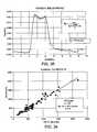
- FIG. 35is a graphical representation of a signal proportional to the hematocrit in the vascular access as recorded by a sensor and associated monitoring system in accordance with the invention.
- FIG. 36is a graphical representation of plotted values of the vascular access flow rate determined using a TQ a sensor in accordance with the present invention versus that determined by a conventional HD01 monitor.
- Hhematocrit
- H ahematocrit within the vascular access site
- H aohematocrit beneath the sensor (outside the dialyzer)
- iintensity of light
- I baselinebaseline intensity (taken in the absence of a bolus)
- I measuredlight back-scattered from a turbid tissue sample
- K baccess site blood coefficient
- TQ atranscutaneous access blood flow
- Vknown volume of saline injected into dialysis venous line
- X bpercentage of the access volume to the total volume illuminated (access blood proration value)
- the optical hematocrit sensor in accordance with the present inventioncomprises a light emitting source (emitter) (preferably an LED of specific wavelength) and a complementary photodetector that can be placed directly on the skin over a vascular access site.
- the LEDpreferably emits light at a wavelength of 805 nm-880 nm, because it is near the known isobestic wavelength for hemoglobin, is commercially available, and has been shown to be effective in the optical determination of whole blood parameters such as hematocrit and oxygen saturation.
- the LEDilluminates a volume of tissue, and a small fraction of the light absorbed and back-scattered by the media is detected by the photodetector. While light travels in a straight line, the illuminated volume as seen by the photodetector can be visualized as an isointensity ellipsoid, as individual photons of light are continuously scattered and absorbed by the media. Because a wavelength of 805 nm-880 nm is used, hemoglobin of the blood within the tissue volume is the principal absorbing substance. The scattering and absorbing characteristics are mathematically expressed in terms of a bulk attenuation coefficient ( ⁇ ) that is specific to the illuminated media. The amount of light detected by the photodetector is proportional via a modified Beer's law formula to the instantaneous net ⁇ value of the media.
- ⁇bulk attenuation coefficient
- the resultant ⁇ valueincludes information about both the surrounding tissue and the access itself.
- the sensor systemilluminates adjacent tissue regions on either side of the access. Values of ⁇ o for tissue regions not containing the access are then used to normalize the signal, thus providing a baseline from which relative changes can be assessed in access hematocrit in the access blood flowing directly under the skin.
- FIG. 1illustrates a dialysis circuit in which a TQ a hematocrit sensor 12 in accordance with the present invention is placed over the hemodialysis vascular access site 14 , with the dialysis arterial and venous blood lines 16 a and 16 b in the normal configuration, for measuring TQ a .
- a dialyzer 20 downstream of the vascular access site 14 and a syringe 22 for injecting a reference diluent (for example, saline) downstream of the dialyzer 20are indicated.
- the hematocrits and flow rates under steady state conditionsare also indicated, where Q a is the access flow rate, Q b is the dialyzer blood flow rate, Q i is the injection flow rate, H a is the hematocrit in the access flow, and H o is the hematocrit at the sensor 12 .
- the hematocrit sensor 12is placed directly on the skin over the vascular access site 14 downstream of the venous dialysis needle 24 .
- the senor 12 and an associated monitoring system 30records a signal proportional to the hematocrit in the vascular access site 14 (H a ).
- the monitoring system 30can be a computer including a computer processor and memory, and output means such as a video monitor and printer (not shown).
- a known volume (V) of normal salineis injected via the syringe 22 into the dialysis venous line 16 b , which reduces the hematocrit beneath the sensor 12 to a time-dependent hematocrit H o during the injection.
- ⁇ Hdenotes H a -H ao
- This equationis valid independent of the rate of saline injection or the dialyzer blood flow rate.
- the signals detected by the TQ a sensor 12can be used to calculate F ⁇ ( ⁇ ⁇ ⁇ H H o ) .
- the percentage change in blood parameters (both macroscopic and microscopic) passing through the access site 14may be measured in a variety of ways. Macroscopic parameters such as bulk density or flow energy can be measured by ultrasonic, temperature, or conductivity means. Microscopic parameters (sometimes called “physiologic or intrinsic” parameters) such as hematocrit or red cell oxygen content are measured by optical means. Each technique has its respective advantages and disadvantages, both rely on the quantity ⁇ ⁇ ⁇ H H .
- the theory on which the construction of the TQ a sensor 12 is basedrequires the use of optical physics and laws associated with optical determination of physiologic elements including hematocrit.
- I ois the radiation intensity emitted from the LED
- Ais a complex function of d and ⁇ of the various layers of tissue (epidermis, dermis, and subcutaneous tissue)
- dis the distance between the LED and detector
- ⁇is the bulk optical attenuation coefficient.
- the ⁇ termis a function of the absorption and scattering nature of the tissue and has a strong dependence on hematocrit.
- a transcutaneously measured ⁇ valueis actually a prorated composite measure of all the absorption and scattering elements contained within the illuminated volume or “glowball” of the emitter source, and typically includes the effects of tissue, water, bone, blood, and in the case of hemodialysis patients, the access site 14 .
- ⁇clearly only the blood flowing through the access site 14 is of interest. The task therefore becomes one of separating the effects of absorption and scattering of the access site 14 from that of surrounding tissue structure.
- Kis the bulk absorption coefficient and S is the bulk scattering coefficient
- X bratio of the access volume to the total volume illuminated
- Cis a proportionality scalar known from the literature or empirically derived.
- measurementsare made in areas 130 b and 130 c near but not including the access site 14 , as depicted, for example, in FIG. 7 . If the tissue is more or less homogenous, it is only necessary to make a single reference ⁇ o measurement, using either two emitters 202 a and 202 b and one detector 204 (as shown in FIG. 13) or one emitter 302 and two detectors 304 a and 304 b (as shown in FIG. 19 ), as discussed in greater detail hereinafter.
- a baseline intensity(taken in the absence of a bolus) is first measured to establish a reference. The intensity is then measured as a time varying signal as the saline bolus is injected , I(t).
- the access blood proration value, X bcancels out. This removes vascular access size, volume, or depth dependence from the final result. Likewise, the di i
- the indicatorIn order to use indicator dilution techniques to measure vascular access flow rates during routine hemodialysis, the indicator must be injected upstream and its concentration detected downstream in the blood flowing through the vascular access site 14 . Reversing the dialysis blood lines 16 a and 16 b during the hemodialysis treatment permits application of indicator dilution by direct injection of the indicator into the dialysis venous tubing 16 b . Because the TQ a sensor 12 can detect a dilution signal downstream of the venous needle 24 through the skin, a unique application of indicator dilution principles permits determination of the vascular access flow rate without reversal of the dialysis blood lines 16 a and 16 b .
- the accuracy of the measurements taken using the TQ a sensor 12depends critically on at least two factors.
- the calculated access flow ratedepends directly on the volume of saline injected; therefore, care must be taken to inject a given amount of saline over a specified time interval. The latter does not need to be known precisely; however, it is important that it be less than approximately 10 seconds to avoid significant interference due to cardiopulmonary recirculation (CPR) of the injected saline.
- CPRcardiopulmonary recirculation
- the second factor that is important to consider in the accuracy of the TQ a measurementsis the placement of the TQ a sensor 12 to accurately determine changes in hematocrit through the skin.
- the sensor 12must be placed directly over the vascular access site 14 approximately 25 mm downstream of the venous needle 24 in the specified orientation to accurately determine the relative changes in hematocrit. Additional variability due to sensor placement does not appear, however, to be significant, in that small variations in sensor placement do not significantly influence the measured vascular access flow rate. An additional concern is whether variations in accuracy of measurements taken using the TQ a sensor 12 may occur with access sites that are not superficial or if the access diameter is very large; however, varying the spacing of sensor elements eliminates difficulties associated with very large accesses or with deeper access sites such as those typically found in the upper arm or thigh. Less accurate results would also be obtained if the sensor 12 does not accurately detect changes in hematocrit due to significant variation in skin pigmentation.
- the TQ a sensor in accordance with the inventionhas been specifically designed to account for the individual absorption and scattering properties of patient tissues, through the use of 805 nm-880 nm LED optical technology, and the normalized nature of the measurements ( di i )
- FIGS. 2-6there is shown a first embodiment of the TQ a sensor 100 in accordance with the present invention for the transcutaneous measurement of vascular access blood flow in a hemodialysis shunt or fistula 14 .
- two emitters 102 a and 102 b and two detectors 104 a and 104 bare arranged in alignment along an axis A 1 on a substrate 110 .
- this embodimentis employed if a gradient in ⁇ o exists in the area of interest (as is often the case in vivo), as multiple measurements must be made to establish the nature of the gradient and provide an averaged estimate of ⁇ o .
- the sensor 100has an access placement line L 1 perpendicular to the axis A 1 .
- the sensor 100must be placed with the access placement line L 1 over the venous access site (shunt) 14 .
- One of the emitters (the “inboard emitter”) 102 a and one of the detectors (the “inboard detector”) 104 aare placed at inboard positions on either side of and equidistant from the access placement line L 1 .
- the second emitter (the “outboard emitter”) 102 bis placed at a position outboard of the inboard detector 104 a
- the second detector (the “outboard detector”) 104 bis placed at a position outboard of the inboard emitter 102 a , so that the emitters 102 a and 102 b and detectors 104 a and 104 b alternate.
- the spacing between the emitters 102 a and 102 b and the detectors 104 a and 104 bis uniform.
- the substrate 110is provided with apertures 116 in its lower surface (the surface which in use faces the access site 20 ) for receiving the emitters 102 a and 102 b and the detectors 104 a and 104 b .
- the apertures 116are sized so that the emitters 102 a and 102 b and the detectors 104 a and 104 b lie flush with the lower surface of the substrate 110 .
- the upper surface of the substrate 110is marked with the access placement line L 1 .
- the upper surface of the substrate 110may also be provided with small projections 120 or other markings above the apertures 116 indicating the locations of the emitters 102 a and 102 b and the detectors 104 a and 104 b.
- the circuitry (not shown) associated with the emitters 102 a and 102 b and the detectors 104 a and 104 bcan be provided as a printed circuit on the lower surface of the substrate 110 .
- the substrate 110is made of a material that is flexible enough to conform to the contours of the underlying tissue but rigid enough to have body durability.
- a first glowball 130 arepresenting the reflective penetration volume ( ⁇ ) of the inboard emitter 102 a through the access site tissue as seen by the inboard detector 104 a in the process of determination of the access Hematocrit
- a second glowball 130 brepresenting the reflective penetration ( ⁇ o1 ) of the inboard emitter 102 a through the non-access site tissue that surrounds the access site 14 as seen by the outboard detector 104 b
- a third glowball 130 crepresenting the reflective penetration ( ⁇ o2 ) of the outboard emitter 102 b through the non-access site tissue that surrounds the access site 14 as seen by the inboard detector 104 a .
- An estimate of ⁇ ois made by averaging ⁇ o1 and ⁇ o2 . That is, ⁇
- the spacing between the inboard emitter 102 a and the inboard detector 104 ais typically 24 mm.
- FIGS. 8-12there is shown a second embodiment of the TQ a sensor 200 in accordance with the present invention.
- two emitters 202 a and 202 b and one detector 204are arranged in alignment along an axis A 2 on a substrate 210 .
- this embodimentis employed if the tissue, T, is more or less homogenous, and it is only necessary to make a single reference ⁇ o measurement.
- the sensor 200has an access placement line L 2 perpendicular to the axis A 2 .
- One of the emitters (the “inboard emitter”) 202 a and the detector 204are placed at inboard positions on either side of and equidistant from the access placement line L 2 .
- the second emitter (the “outboard emitter”) 202 bis placed at a position outboard of the detector 204 , so that the emitters 202 a and 202 b and the detector 204 alternate.
- the spacing between the emitters 202 a and 202 b and the detector 204is uniform.
- the substrate 210is provided with apertures 216 in its lower surface for receiving the emitters 202 a and 202 b and the detector 204 .
- the apertures 216are sized so that the emitters 202 a and 202 b and the detector 204 lie flush with the lower surface of the substrate 210 .
- the upper surface of the substrate 210is marked with the access placement line L 2 , and also is marked with “plus” and “minus” signs 218 a and 218 b , which indicate the direction to move the sensor 200 left or right.
- the upper surface of the substrate 210may also be provided with small projections 220 or other markings above the apertures 216 indicating the locations of the emitters 202 a and 202 b and the detector 204 .
- the circuitry (not shown) associated with the emitters 202 a and 202 b and the detector 204can be provided as a printed circuit on the lower surface of the substrate 210 .
- the substrate 210is made of a material that is flexible enough to conform to the contours of the underlying tissue but rigid enough to have body durability.
- FIG. 13there are two illuminated “glowballs” 230 a and 230 b seen by the single detector 204 : a first glowball 230 a representing the reflective penetration ( ⁇ ) of the inboard emitter 202 a through the access site tissue as seen by the single detector 204 in the process of determination of the access Hematocrit; and a second glowball 230 b representing the reflective penetration ( ⁇ o ) of the outboard emitter 202 b through the non-access site tissue that surrounds the access site 14 as seen by the single detector 204 .
- a first glowball 230 arepresenting the reflective penetration ( ⁇ ) of the inboard emitter 202 a through the access site tissue as seen by the single detector 204 in the process of determination of the access Hematocrit
- a second glowball 230 brepresenting the reflective penetration ( ⁇ o ) of the outboard emitter 202 b through the non-access site tissue that surrounds the access site 14 as seen by the single detector 204 .
- FIGS. 14-18there is shown a third embodiment of the TQ a sensor 300 in accordance with the present invention.
- the third embodimentis similar to the second embodiment, except that one emitter 302 and two detector 304 a and 304 b are arranged in alignment along an axis A 3 on a substrate 310 .
- the sensor 300has an access placement line L 3 perpendicular to the axis A 3 .
- the emitter 302 and one of the detectors (the “inboard detector”) 304 aare placed at inboard positions on either side of and equidistant from the access placement line L 3 .
- the second detector (the “outboard detector”) 304 bis placed at a position outboard of the emitter 302 , so that the emitter 302 and the detectors 304 a and 304 b alternate.
- the spacing between the emitter 302 and the detectors 304 a and 304 bis uniform.
- the substrate 310is provided with apertures 316 in its lower surface for receiving the emitter 302 and the detectors 3204 a and 3204 b .
- the apertures 316are sized so that the emitter 302 and the detectors 304 a and 304 b lie flush with the lower surface of the substrate 210 .
- the circuitry (not shown) associated with the emitter 302 and the detectors 304 a and 304 bcan be provided as a printed circuit on the lower surface of the substrate 310 .
- the substrate 310is made of a material that is flexible enough to conform to the contours of the underlying tissue but rigid enough to have body durability.
- the upper surface of the substrate 310is marked with the access placement line L 3 , and also is marked with “plus” and “minus” signs 318 a and 318 b , which indicate the direction to move the sensor 300 left or right.
- the upper surface of the substrate 310may also be provided with small projections 320 or other markings above the apertures 316 indicating the locations of the emitter 302 and the detectors 304 a and 304 b.
- a first glowball 330 arepresenting the reflective penetration ( ⁇ ) of the single emitter 302 through the access tissue as seen by the inboard detector 304 a in the process of determination of the access Hematocrit
- a second glowball 330 brepresenting the reflective penetration ( ⁇ o ) of the single emitter 302 through the non-access site tissue that surrounds the access site 14 as seen by the outboard detector 304 b
- the placement of the emitters and detectorspermits all of the measurements to be made only in tissue volumes perpendicular to the access site 14 .
- the placement of the emitters and detectorspermits measurements to be made in tissue areas parallel, as well as perpendicular, to the access site 14 .
- a flexible components layer 410is provided having an access placement line L 4 .
- An upstream and a downstream emitter 402 a and 402 bare arranged on the components layer 410 along a first diagonal line D 1 forming a 45° angle with the access placement line L 4 , and an upstream and a downstream detector 404 a and 404 b are arranged along a second line D 2 perpendicular to the first line at its point of intersection P with the access placement line L 4 .
- the upstream and downstream emitters 402 a and 402 b and the upstream and downstream detectors 404 a and 404 bare equidistant from the point of intersection P. It will thus be seen that the upstream emitter 402 a and the downstream detector 404 b lie on one side of the access placement line L 4 along a line parallel thereto, and the upstream detector 404 a and the downstream emitter 402 b lie on the other side of the access placement line L 4 along a line parallel thereto; and that the upstream emitter 402 a and the upstream detector 404 a lie along a line perpendicular to the access placement line L 4 , as do the downstream emitter 402 b and the downstream detector 404 b.
- the circuitry associated with the emitters 402 a and 402 b and the detectors 404 a and 404 bis also incorporated in the flexible components layer 410 .
- the components layer 410has a lower surface that faces the access site 14 , and an upper surface that faces away.
- the emitters 402 a and 402 b and the detectors 404 a and 404 bmay protrude from the lower surface of the components layer 410 .
- a cover layer 412 of flexible foam or the likecovers the upper surface of the components layer 410 .
- a spacer layer 414 of flexible foam or the likecovers the lower surface of the components layer 410 , and has apertures 416 in registration with the emitters 402 a and 402 b and the detectors 404 a and 404 b , so that each emitter and detector is received in its own corresponding aperture 416 .
- the spacer layer 414has an upper surface that contacts the lower surface of the components layer 410 and a lower surface that faces away from the components layer 410 .
- the upper surface of the cover layer 412is marked with the access placement line L 4 , and also is marked to indicate which end of the access placement line L 4 is to be placed adjacent the venous needle 24 , to assist in proper placement.
- the TQ a sensor 400preferably is elongated in the direction of the access placement line L 4 , in order to ensure the proper placement of the emitters 402 a and 402 b and the detectors 404 a and 404 b relative to the venous needle 24 .
- a transparent adhesive layer 420can be applied to the lower surface of the spacer layer 414 .
- the adhesivecan be any suitable pressure sensitive adhesive.
- a release liner 422covers the adhesive layer 420 . Prior to use, the release layer 424 is removed from the adhesive layer 420 of the TQ a sensor 400 , and the TQ a sensor 400 is adhered to the access site 14 .
- FIGS. 23-26there are four illuminated “glowballs” seen by the upstream and downstream detectors: a first glowball 430 a representing the reflective penetration ( ⁇ ) of the upstream emitter 402 a through the access site tissue as seen by the upstream detector 404 a in the process of determination of the access hematocrit (FIG. 23 ); a second glowball 430 b representing the reflective penetration ( ⁇ ) of the downstream emitter 402 b through the access site tissue as seen by the downstream detector 404 b in the process of determination of the access Hematocrit (FIG.
- a third glowball 430 crepresenting the reflective penetration ( ⁇ o1 ) of the upstream emitter 402 a through the non-access site tissue that surrounds the access site 14 as seen by the downstream detector 404 b (FIG. 25 ); and a fourth glowball 430 d representing the reflective penetration ( ⁇ o2 ) of the downstream emitter 404 b through the non-access site tissue that surrounds the access site 14 as seen by the upstream detector 404 a (FIG. 26 ).
- An estimate of ⁇ ois again made by averaging ⁇ o1 and ⁇ o2 .
- a substrate 510is provided having an access placement line L 5 .
- a first upstream emitter 502 a and a downstream emitter 502 bare arranged on the substrate 510 along a first diagonal line D 3 forming a 45° angle with the access placement line L 5
- upstream and downstream detectors 504 a and 504 bare arranged along a second line D 4 perpendicular to the first line at its point of intersection P with the access placement line L 4 , exactly as in the fourth embodiment, with the first upstream and the downstream emitters 502 a and 502 b and the upstream and downstream detectors 504 a and 504 b being equidistant from the point of intersection P.
- the second, third, fourth, fifth, and sixth upstream detectors 502 c , 502 d , 502 e , 502 f , and 502 gare arranged in alignment along a line defined by the first upstream emitter 502 a and the upstream detector 504 a , with the fourth detector 502 e lying on the access placement line L 5 .
- the second, third, fourth, fifth, and sixth emitters 502 c , 502 d , 502 e , 502 f , and 502 gare uniformly spaced between the first upstream emitter 502 a and the upstream detector 504 a and can be used to locate the access.
- pairs of emitters 502 a and 502 c - 502 gcan be used to determine the diameter of the access.
- the cover layer 512 , spacer layer 514 , adhesive layer 522 , and release liner 524 of the sensor 500 in accordance with the fifth embodimentare identical to those of the sensor 400 of the fourth embodiment, except that the apertures 516 in the spacer layer 514 will be placed in accordance with the placement of the emitters 502 a - 502 g and the detectors 504 a and 504 b in the components layer 510 of the fifth embodiment.
- FIGS. 30 and 31there are six illuminated glowballs perpendicular to the access site 14 and one illuminated glowball parallel to the access site 14 that are seen by the upstream detector 504 a : a first glowball 530 a representing the reflective penetration ( ⁇ ) of the first upstream emitter 502 a through the access site tissue in the process of determination of the access site Hematocrit (FIG. 30 ); a second glowball 530 b representing the reflective penetration ( ⁇ o1 ) of the downstream emitter 502 b through the non-access site tissue that is parallel to the access site 14 (FIG.
- a third glowball 530 crepresenting the reflective penetration of the second upstream emitter 502 c through both non-access and some of the access volume (FIG. 30 ); a fourth glowball 530 d representing the reflective penetration of the third upstream emitter 502 d through both non-access and some of the access volume (FIG. 30 ); a fifth glowball 530 e representing the reflective penetration of the fourth upstream emitter 502 e through both non-access and some of the access volume (FIG. 30 ); a sixth glowball 530 f representing the reflective penetration of the fifth upstream emitter 502 f through non-access the access volume (FIG. 30 ); and a seventh glowball 530 g representing the reflective penetration of the sixth upstream emitter 502 g through non-access volume (FIG. 30 ).
- FIGS. 32 and 33there are two illuminated “glowballs” seen by the downstream detector 504 b : an eighth glowball 530 h representing the reflective penetration ( ⁇ o2 ) of the first upstream emitter 502 a through the non-access site tissue that is parallel to the access site 14 (FIG. 32 ); and a second glowball 530 i representing the reflective penetration ( ⁇ ) of the downstream emitter 502 b through the access site tissue in the process of determination of the access Hematocrit (FIG. 33 ).
- An estimate of ⁇ ois made by averaging ⁇ o1 and ⁇ 02 , and then using equation (13) to determine F ⁇ ( ⁇ ⁇ ⁇ H H ) .
- the spacing between the first upstream emitter 502 a and the upstream detector 504 ais typically 24 mm.
- the remaining upstream emitters 502 c - 502 gare equally spaced between the first upstream emitter 502 a and the upstream detector 504 a .
- the spacing between the downstream emitter 502 b and the downstream detector 504 bare typically 24 mm.
- the emittersare preferably LEDs that emit light at a wavelength of 805 nm-880 nm
- the detectorsare silicon photodiodes.
- the substratepreferably is provided with an exterior covering (see FIG. 34) of a plastic material, for example urethane or silicone, and the emitters and detectors lie flush with the lower surface of the exterior covering, that is, the surface that faces the skin, so that the emitters and detectors lie on the skin.
- each emitter and detectoris recessed in an aperture. The fourth and fifth embodiments use more LED's than the other embodiments.
- an emitter-detector separationis required so that the reflectance of the first layer of tissue (a non-blood layer of epithelium) does not further exaggerate a multiple scattering effect, as discussed in U.S. Pat. No. 5,499,627, which is incorporated herein by reference in its entirety.
- the distance between each adjacent pair of emitters and detectorsmust be sufficient for a portion of the access site 14 to be enclosed within the illuminated volume or “glowball” of the inboard emitter. This distance typically is about 24 mm, except as described above with respect to the fifth embodiment.
- a sensor 600includes a substrate 610 that houses a plurality of emitters and detectors (not shown) as previously described, a circuit 652 printed on the skin side of the substrate 610 , and an exterior covering 654 covering the circuit 652 and the exposed sides of the substrate 610 .
- the substrate 610can comprise a flexible material such as MYLAR on which conductive paint has been deposited to define a circuit.
- Apertures 656are formed through the skin side of the exterior covering 654 in registration with circuit junctions that are covered by conductive paint that allows continuity across the junctions. Plugs 660 are inserted into the apertures 656 in such a fashion that they adhere to the conductive paint at the circuit junctions.
- the skin side of the exterior covering 654is covered by a removable protective layer 662 , to which the plugs 660 are also affixed.
- the protective surface protective layer 662must be removed in order for the sensor 600 to take a measurement. Because the plugs 660 are adhered to the protective layer 662 , when the protective layer 662 is peeled off, the plugs 660 are pulled out of their apertures 656 along with the conductive paint covering the circuit junctions.
- the circuitryis designed such that once the circuit is broken, the sensor 600 cannot be calibrated again, and can only be used to take one measurement. The sensor 600 thus cannot be re-used.
- TQ a sensor in accordance with the inventionOperability of the TQ a sensor in accordance with the invention was confirmed in in vivo tests in 59 hemodialysis patients.
- a disposable tubing with an injection portCO-daptoR, Transonic Systems, Ithaca, N.Y., USA
- the dialysis circuitwas primed with saline in usual fashion taking extra care to remove any air bubbles from the venous injection port.
- the transcutaneous hematocrit sensorwas placed on the skin over the patient's vascular access approximately 25 mm downstream of the venous needle. Thirty ml of normal saline solution were then injected into the injection port of the disposable tubing adjacent to the venous needle at a rate of approximately 300 ml/min to determine access blood flow rate using the TQ a sensor of the invention. In six patients, saline was injected directly into the arterial dialysis needle before connecting the needle to the complete dialysis circuit. In two patients, saline was injected directly into the access by using a needle and syringe. The data from these various methods were combined together, independent of where saline was injected into the access. The resulting F ⁇ ( ⁇ ⁇ ⁇ H H )
- the patients studiedwere predominantly male and Caucasian; 5 Black and 1 Native American patients were studied. Although the distribution of patient race in the study was not representative of that within the United States as a whole, it was representative of the population in the geographical region where the test was conducted.
- the age of the patients, the fraction of diabetic patients and the fraction of patients with synthetic PTFE graftswere similar to those for chronic hemodialysis patients in the United States. Eleven patients were studied twice and one patient was studied three times. All other patients were studied once for a total of 72 measurements. Access recirculation was significant in three patients. In those patients, the blood pump setting was reduced to 150 ml/min to eliminate access recirculation before completing the study protocol.
- FIG. 36shows values of the vascular access flow rate determined using the TQ a sensor plotted versus that determined by the HD01 monitor.
- the best-fit linear regression linehas a slope of essentially unity and a small y-intercept.
- the optical TQ a sensor in accordance with the inventioncan accurately determine instantaneous changes in hematocrit, it permits use of the bolus injection indicator dilution approach (Henriques-Hamilton-Bergner Principle).
- This optical approachis likely to be of considerable interest to nephrologists since it is also possible to determine the vascular access flow rate when the patient is in the physician's office or in the clinic and not being treated by hemodialysis by simply injecting saline directly into the access and measuring with a downstream TQ a sensor.
- eight patientshad vascular access flow rate determinations by direct injection of saline into the access prior to dialysis; their results were later confirmed once the dialysis circuit was in place and functioning.
- TQ a sensor in accordance with the inventionmay now be possible to use the TQ a sensor in accordance with the invention to regularly monitor the vascular access flow rate as an indicator of access function when the patient is not being dialyzed, as well as during maturation of native fistulas prior to first use.
- the senor in accordance with the present inventioncan be used to measure blood constituents other than hematocrit, such as albumen and glucose, in which case the LEDs emit different wavelengths suited to the specific constituent.
- the detector-emitter arrangement of the sensor in accordance with the present inventionallows for precise access location, as a “flow finder,” and also can be used to locate grafts and to localize veins in normal patients for more efficient canulatization.
- the sensor 110is placed directly on the skin over the approximate area of the access, graft, or vein, and values of ⁇ , ⁇ o1 , and ⁇ o2 are calculated as described above.
- SSsignal strength
- SS>40a sufficient amount of the access or graft or vein is within the illuminated volume of tissue. If RR is not ⁇ 15 (that is, if RR ⁇ 15), or if SS is not>40 (that is, if SS is ⁇ 40), then the sensor 110 is moved right or left (+ or ⁇ ) to find the appropriate spot or location.
Landscapes
- Health & Medical Sciences (AREA)
- Life Sciences & Earth Sciences (AREA)
- Heart & Thoracic Surgery (AREA)
- Physics & Mathematics (AREA)
- General Health & Medical Sciences (AREA)
- Veterinary Medicine (AREA)
- Engineering & Computer Science (AREA)
- Animal Behavior & Ethology (AREA)
- Public Health (AREA)
- Biomedical Technology (AREA)
- Pathology (AREA)
- Medical Informatics (AREA)
- Molecular Biology (AREA)
- Surgery (AREA)
- Biophysics (AREA)
- Vascular Medicine (AREA)
- Hematology (AREA)
- Cardiology (AREA)
- Optics & Photonics (AREA)
- Anesthesiology (AREA)
- Spectroscopy & Molecular Physics (AREA)
- Physiology (AREA)
- Analytical Chemistry (AREA)
- Immunology (AREA)
- General Physics & Mathematics (AREA)
- Biochemistry (AREA)
- Chemical & Material Sciences (AREA)
- Fluid Mechanics (AREA)
- External Artificial Organs (AREA)
- Measurement Of The Respiration, Hearing Ability, Form, And Blood Characteristics Of Living Organisms (AREA)
- Measuring Pulse, Heart Rate, Blood Pressure Or Blood Flow (AREA)
Abstract
Description


Claims (13)
Priority Applications (11)
| Application Number | Priority Date | Filing Date | Title |
|---|---|---|---|
| US09/750,076US6725072B2 (en) | 1990-10-06 | 2000-12-29 | Sensor for transcutaneous measurement of vascular access blood flow |
| KR10-2003-7008841AKR20030081369A (en) | 2000-12-29 | 2001-12-20 | Sensor for transcutaneous measurement of vascular access blood flow |
| PCT/US2001/048562WO2002053025A2 (en) | 2000-12-29 | 2001-12-20 | Sensor for transcutaneous measurement of vascular access blood flow |
| EP01996251AEP1345529A2 (en) | 2000-12-29 | 2001-12-20 | Sensor for transcutaneous measurement of vascular access blood flow |
| AU2002227400AAU2002227400A1 (en) | 2000-12-29 | 2001-12-20 | Sensor for transcutaneous measurement of vascular access blood flow |
| JP2002553980AJP2004523268A (en) | 2000-12-29 | 2001-12-20 | Sensor for percutaneous measurement of vascular access blood flow |
| CA002433278ACA2433278A1 (en) | 2000-12-29 | 2001-12-20 | Sensor for transcutaneous measurement of vascular access blood flow |
| US10/099,974US6804543B2 (en) | 1998-02-05 | 2002-03-19 | Sensor for transcutaneous measurement of vascular access blood flow |
| US10/730,005US6937882B2 (en) | 2000-12-29 | 2003-12-09 | Sensor for transcutaneous measurement of vascular access blood flow |
| US10/730,102US6987993B2 (en) | 2000-12-29 | 2003-12-09 | Sensor for transcutaneous measurement of vascular access blood flow |
| US10/730,000US20040116817A1 (en) | 1990-10-06 | 2003-12-09 | Sensor for transcutaneous measurement of vascular access blood flow |
Applications Claiming Priority (8)
| Application Number | Priority Date | Filing Date | Title |
|---|---|---|---|
| US59816990A | 1990-10-06 | 1990-10-06 | |
| US08/011,882US5372136A (en) | 1990-10-06 | 1993-02-01 | System and method for noninvasive hematocrit monitoring |
| US08/317,726US5499627A (en) | 1990-10-06 | 1994-10-04 | System for noninvasive hematocrit monitoring |
| US08/479,352US5803908A (en) | 1990-10-06 | 1995-06-07 | System for noninvasive hematocrit monitoring |
| US7378498P | 1998-02-05 | 1998-02-05 | |
| US09/084,958US6266546B1 (en) | 1990-10-06 | 1998-05-28 | System for noninvasive hematocrit monitoring |
| US09/244,756US6181958B1 (en) | 1998-02-05 | 1999-02-05 | Method and apparatus for non-invasive blood constituent monitoring |
| US09/750,076US6725072B2 (en) | 1990-10-06 | 2000-12-29 | Sensor for transcutaneous measurement of vascular access blood flow |
Related Parent Applications (2)
| Application Number | Title | Priority Date | Filing Date |
|---|---|---|---|
| US09/084,958Continuation-In-PartUS6266546B1 (en) | 1990-10-06 | 1998-05-28 | System for noninvasive hematocrit monitoring |
| US09/244,756Continuation-In-PartUS6181958B1 (en) | 1990-10-06 | 1999-02-05 | Method and apparatus for non-invasive blood constituent monitoring |
Related Child Applications (4)
| Application Number | Title | Priority Date | Filing Date |
|---|---|---|---|
| US10/099,974Continuation-In-PartUS6804543B2 (en) | 1998-02-05 | 2002-03-19 | Sensor for transcutaneous measurement of vascular access blood flow |
| US10/730,000ContinuationUS20040116817A1 (en) | 1990-10-06 | 2003-12-09 | Sensor for transcutaneous measurement of vascular access blood flow |
| US10/730,005DivisionUS6937882B2 (en) | 1990-10-06 | 2003-12-09 | Sensor for transcutaneous measurement of vascular access blood flow |
| US10/730,102DivisionUS6987993B2 (en) | 2000-12-29 | 2003-12-09 | Sensor for transcutaneous measurement of vascular access blood flow |
Publications (2)
| Publication Number | Publication Date |
|---|---|
| US20010003793A1 US20010003793A1 (en) | 2001-06-14 |
| US6725072B2true US6725072B2 (en) | 2004-04-20 |
Family
ID=25016382
Family Applications (4)
| Application Number | Title | Priority Date | Filing Date |
|---|---|---|---|
| US09/750,076Expired - Fee RelatedUS6725072B2 (en) | 1990-10-06 | 2000-12-29 | Sensor for transcutaneous measurement of vascular access blood flow |
| US10/730,102Expired - Fee RelatedUS6987993B2 (en) | 2000-12-29 | 2003-12-09 | Sensor for transcutaneous measurement of vascular access blood flow |
| US10/730,005Expired - Fee RelatedUS6937882B2 (en) | 1990-10-06 | 2003-12-09 | Sensor for transcutaneous measurement of vascular access blood flow |
| US10/730,000AbandonedUS20040116817A1 (en) | 1990-10-06 | 2003-12-09 | Sensor for transcutaneous measurement of vascular access blood flow |
Family Applications After (3)
| Application Number | Title | Priority Date | Filing Date |
|---|---|---|---|
| US10/730,102Expired - Fee RelatedUS6987993B2 (en) | 2000-12-29 | 2003-12-09 | Sensor for transcutaneous measurement of vascular access blood flow |
| US10/730,005Expired - Fee RelatedUS6937882B2 (en) | 1990-10-06 | 2003-12-09 | Sensor for transcutaneous measurement of vascular access blood flow |
| US10/730,000AbandonedUS20040116817A1 (en) | 1990-10-06 | 2003-12-09 | Sensor for transcutaneous measurement of vascular access blood flow |
Country Status (7)
| Country | Link |
|---|---|
| US (4) | US6725072B2 (en) |
| EP (1) | EP1345529A2 (en) |
| JP (1) | JP2004523268A (en) |
| KR (1) | KR20030081369A (en) |
| AU (1) | AU2002227400A1 (en) |
| CA (1) | CA2433278A1 (en) |
| WO (1) | WO2002053025A2 (en) |
Cited By (19)
| Publication number | Priority date | Publication date | Assignee | Title |
|---|---|---|---|---|
| US20130261414A1 (en)* | 2012-03-29 | 2013-10-03 | Card Guard Scientific Survival Ltd | Hand-held device having health monitoring capabilities |
| WO2015185202A1 (en) | 2014-06-06 | 2015-12-10 | Fresenius Medical Care Deutschland Gmbh | Device for the non-invasive measurement of blood flow |
| WO2016209998A1 (en)* | 2015-06-22 | 2016-12-29 | Fresenius Medical Care Holdings, Inc. | Transcutaneous measurement of hemoglobin changes to calculate estimated blood volume change during peritoneal dialysis |
| US9788794B2 (en) | 2014-02-28 | 2017-10-17 | Valencell, Inc. | Method and apparatus for generating assessments using physical activity and biometric parameters |
| US9808204B2 (en) | 2007-10-25 | 2017-11-07 | Valencell, Inc. | Noninvasive physiological analysis using excitation-sensor modules and related devices and methods |
| US9955919B2 (en) | 2009-02-25 | 2018-05-01 | Valencell, Inc. | Light-guiding devices and monitoring devices incorporating same |
| US9993204B2 (en) | 2013-01-09 | 2018-06-12 | Valencell, Inc. | Cadence detection based on inertial harmonics |
| US10076282B2 (en) | 2009-02-25 | 2018-09-18 | Valencell, Inc. | Wearable monitoring devices having sensors and light guides |
| US10258243B2 (en) | 2006-12-19 | 2019-04-16 | Valencell, Inc. | Apparatus, systems, and methods for measuring environmental exposure and physiological response thereto |
| US10281454B2 (en) | 2015-06-24 | 2019-05-07 | Fresenius Medical Care Holdings, Inc. | Tunable optical receiver |
| US10349844B2 (en) | 2012-01-16 | 2019-07-16 | Valencell, Inc. | Reduction of physiological metric error due to inertial cadence |
| US10390762B2 (en) | 2012-01-16 | 2019-08-27 | Valencell, Inc. | Physiological metric estimation rise and fall limiting |
| US10413197B2 (en) | 2006-12-19 | 2019-09-17 | Valencell, Inc. | Apparatus, systems and methods for obtaining cleaner physiological information signals |
| US10512403B2 (en) | 2011-08-02 | 2019-12-24 | Valencell, Inc. | Systems and methods for variable filter adjustment by heart rate metric feedback |
| US10610158B2 (en) | 2015-10-23 | 2020-04-07 | Valencell, Inc. | Physiological monitoring devices and methods that identify subject activity type |
| US10827979B2 (en) | 2011-01-27 | 2020-11-10 | Valencell, Inc. | Wearable monitoring device |
| US10888255B2 (en) | 2017-09-26 | 2021-01-12 | Samsung Electronics Co., Ltd. | Biological component estimation apparatus and operation method thereof |
| US10945618B2 (en) | 2015-10-23 | 2021-03-16 | Valencell, Inc. | Physiological monitoring devices and methods for noise reduction in physiological signals based on subject activity type |
| US10966662B2 (en) | 2016-07-08 | 2021-04-06 | Valencell, Inc. | Motion-dependent averaging for physiological metric estimating systems and methods |
Families Citing this family (28)
| Publication number | Priority date | Publication date | Assignee | Title |
|---|---|---|---|---|
| US6725072B2 (en)* | 1990-10-06 | 2004-04-20 | Hema Metrics, Inc. | Sensor for transcutaneous measurement of vascular access blood flow |
| SE524166C2 (en)* | 2002-05-17 | 2004-07-06 | Hemapure Ab | Sensor unit and method for detecting a blood related parameter and system comprising such sensor unit |
| US20080132797A1 (en)* | 2002-12-10 | 2008-06-05 | Knut Brabrand | Monitoring infusion of a substance |
| JP3590047B1 (en)* | 2003-09-24 | 2004-11-17 | 株式会社日立製作所 | Optical measuring device and blood glucose measuring device using the same |
| US20060094941A1 (en)* | 2004-10-29 | 2006-05-04 | Ok-Kyung Cho | Optical measurement apparatus and blood sugar level measuring apparatus using the same |
| GB0603006D0 (en)* | 2006-02-15 | 2006-03-29 | Dialog Devices Ltd | Assessing blood supply to a peripheral portion of an animal |
| RU2309668C1 (en) | 2006-02-20 | 2007-11-10 | Александр Сергеевич Парфенов | Method and device for non-invasive measurement of function of endothelium |
| US8639309B2 (en) | 2007-07-31 | 2014-01-28 | J&M Shuler, Inc. | Method and system for monitoring oxygenation levels of compartments and tissue |
| US8100834B2 (en)* | 2007-02-27 | 2012-01-24 | J&M Shuler, Inc. | Method and system for monitoring oxygenation levels of a compartment for detecting conditions of a compartment syndrome |
| KR100905571B1 (en) | 2007-07-19 | 2009-07-02 | 삼성전자주식회사 | Biometric information measuring device |
| US9011334B2 (en) | 2007-09-27 | 2015-04-21 | Baxter International Inc. | Access disconnect detection |
| WO2009061769A1 (en)* | 2007-11-06 | 2009-05-14 | Alfred E. Mann Institute For Biomedical Engineering At The University Of Southern Califorina | Measurement of hematocrit and cardiac output from optical transmission and reflection changes |
| JP5222706B2 (en)* | 2008-12-04 | 2013-06-26 | 日機装株式会社 | Blood purification apparatus and blood flow calculation method thereof |
| US8057400B2 (en) | 2009-05-12 | 2011-11-15 | Angiologix, Inc. | System and method of measuring changes in arterial volume of a limb segment |
| KR101707701B1 (en) | 2009-06-26 | 2017-02-16 | 감브로 룬디아 아베 | Devices, a computer program product and a method for data extraction |
| US20110060224A1 (en)* | 2009-08-09 | 2011-03-10 | Tz Medical, Inc. | Non-invasive continuous doppler monitoring device for arterial blood flow to distal body parts |
| EP2519279B1 (en)* | 2009-12-28 | 2015-04-22 | Gambro Lundia AB | Device and method for monitoring a fluid flow rate in a cardiovascular system |
| US9132273B2 (en) | 2010-10-14 | 2015-09-15 | II Erich W. Wolf | Apparatus and method using near infrared reflectometry to reduce the effect of positional changes during spinal cord stimulation |
| US8239038B2 (en)* | 2010-10-14 | 2012-08-07 | Wolf Ii Erich W | Apparatus and method using near infrared reflectometry to reduce the effect of positional changes during spinal cord stimulation |
| US9550063B2 (en) | 2010-10-14 | 2017-01-24 | II Erich W. Wolf | Apparatus and method using near infrared reflectometry to reduce the effect of positional changes during spinal cord stimulation |
| US9656097B2 (en) | 2010-10-14 | 2017-05-23 | II Erich W. Wolf | Apparatus and method using near infrared reflectometry to reduce the effect of positional changes during spinal cord stimulation |
| EP2565624A1 (en)* | 2011-09-05 | 2013-03-06 | Carl Freudenberg KG | Sensor head for use in transcutaneous organ function measurements |
| KR20180015171A (en) | 2015-05-26 | 2018-02-12 | 비에스엑스 애슐레틱스 | Device and method for determining biological indicator levels of tissue |
| EP3111842B1 (en)* | 2015-06-30 | 2025-01-22 | Nokia Technologies Oy | An apparatus comprising a light detector, a light source and optics |
| AU2018244596B2 (en)* | 2017-03-29 | 2022-03-31 | Alio, Inc. | Wearable device with multimodal diagnostics |
| ES3015552T3 (en) | 2018-07-16 | 2025-05-06 | Bbi Medical Innovations Llc | Perfusion and oxygenation measurement |
| US11742080B2 (en)* | 2020-06-10 | 2023-08-29 | Fresenius Medical Care Holdings, Inc. | Secure artificial intelligence enabled wearable medical sensor platforms |
| JP7725878B2 (en)* | 2021-06-03 | 2025-08-20 | 株式会社ジェイ・エム・エス | Blood purification device |
Citations (67)
| Publication number | Priority date | Publication date | Assignee | Title |
|---|---|---|---|---|
| US3638640A (en) | 1967-11-01 | 1972-02-01 | Robert F Shaw | Oximeter and method for in vivo determination of oxygen saturation in blood using three or more different wavelengths |
| US3880151A (en) | 1972-07-12 | 1975-04-29 | Siemens Elema Ab | Pressure receiver |
| US3998550A (en)* | 1974-10-14 | 1976-12-21 | Minolta Camera Corporation | Photoelectric oximeter |
| US4014321A (en) | 1974-11-25 | 1977-03-29 | March Wayne F | Non-invasive glucose sensor system |
| US4081372A (en) | 1975-12-08 | 1978-03-28 | University Of Utah | Leakage indicator for recirculating peritoneal dialysis system |
| US4086915A (en) | 1975-04-30 | 1978-05-02 | Harvey I. Kofsky | Ear oximetry process and apparatus |
| US4167331A (en) | 1976-12-20 | 1979-09-11 | Hewlett-Packard Company | Multi-wavelength incremental absorbence oximeter |
| US4181610A (en) | 1975-07-14 | 1980-01-01 | Takeda Chemical Industries, Ltd. | Blood leak detector suitable for use with artificial kidneys |
| US4223680A (en) | 1977-06-28 | 1980-09-23 | Duke University, Inc. | Method and apparatus for monitoring metabolism in body organs in vivo |
| US4266554A (en) | 1978-06-22 | 1981-05-12 | Minolta Camera Kabushiki Kaisha | Digital oximeter |
| US4295470A (en) | 1976-10-18 | 1981-10-20 | Oximetrix, Inc. | Optical catheters and method for making same |
| US4416285A (en) | 1978-11-29 | 1983-11-22 | Oximetrix, Inc. | Improved optical catheter and method for making same |
| US4446871A (en) | 1980-01-25 | 1984-05-08 | Minolta Kabushiki Kaisha | Optical analyzer for measuring a construction ratio between components in the living tissue |
| WO1986006946A1 (en) | 1985-05-30 | 1986-12-04 | Baxter Travenol Laboratories, Inc. | Method and apparatus for determining oxygen saturation in vivo |
| US4653498A (en) | 1982-09-13 | 1987-03-31 | Nellcor Incorporated | Pulse oximeter monitor |
| US4655225A (en) | 1985-04-18 | 1987-04-07 | Kurabo Industries Ltd. | Spectrophotometric method and apparatus for the non-invasive |
| US4685464A (en) | 1985-07-05 | 1987-08-11 | Nellcor Incorporated | Durable sensor for detecting optical pulses |
| US4714080A (en) | 1986-10-06 | 1987-12-22 | Nippon Colin Co., Ltd. | Method and apparatus for noninvasive monitoring of arterial blood oxygen saturation |
| US4770179A (en) | 1982-09-02 | 1988-09-13 | Nellcor Incorporated | Calibrated optical oximeter probe |
| US4805623A (en) | 1987-09-04 | 1989-02-21 | Vander Corporation | Spectrophotometric method for quantitatively determining the concentration of a dilute component in a light- or other radiation-scattering environment |
| US4819752A (en) | 1987-10-02 | 1989-04-11 | Datascope Corp. | Blood constituent measuring device and method |
| US4821734A (en) | 1987-04-21 | 1989-04-18 | Nihon Seimitsu Sokki Co., Ltd. | Sphygmomanometer |
| US4824242A (en) | 1986-09-26 | 1989-04-25 | Sensormedics Corporation | Non-invasive oximeter and method |
| US4825872A (en) | 1988-08-05 | 1989-05-02 | Critikon, Inc. | Finger sensor for pulse oximetry system |
| US4825879A (en) | 1987-10-08 | 1989-05-02 | Critkon, Inc. | Pulse oximeter sensor |
| EP0160768B1 (en) | 1984-05-04 | 1989-05-03 | Kurabo Industries Ltd. | Spectrophotometric apparatus for the non-invasive determination of glucose in body tissues |
| US4832484A (en) | 1986-10-29 | 1989-05-23 | Nihon Kohden Corporation | Apparatus for determining the concentration of a light-absorbing material in blood |
| US4863265A (en) | 1987-10-16 | 1989-09-05 | Mine Safety Appliances Company | Apparatus and method for measuring blood constituents |
| US4867557A (en) | 1987-04-09 | 1989-09-19 | Sumitomo Electric Industries, Ltd. | Reflection type oximeter for applying light pulses to a body tissue to measure oxygen saturation |
| EP0104772B1 (en) | 1982-09-02 | 1990-03-21 | Nellcor Incorporated | Calibrated optical oximeter probe |
| US4920972A (en) | 1987-01-27 | 1990-05-01 | Medex, Inc. | Gel-filled blood pressure transducer |
| US4925299A (en) | 1987-08-10 | 1990-05-15 | Fresenius Ag | Hemoglobin detector |
| US5028787A (en) | 1989-01-19 | 1991-07-02 | Futrex, Inc. | Non-invasive measurement of blood glucose |
| US5035243A (en) | 1988-03-26 | 1991-07-30 | Nicolay Gmbh | Holder sleeve for positioning a detecting and measuring sensor |
| US5048524A (en) | 1989-03-03 | 1991-09-17 | Camino Laboratories, Inc. | Blood parameter measurement |
| US5054487A (en) | 1990-02-02 | 1991-10-08 | Boston Advanced Technologies, Inc. | Laser systems for material analysis based on reflectance ratio detection |
| US5057695A (en) | 1988-12-19 | 1991-10-15 | Otsuka Electronics Co., Ltd. | Method of and apparatus for measuring the inside information of substance with the use of light scattering |
| US5058587A (en) | 1988-08-23 | 1991-10-22 | Terumo Kabushiki Kaisha | Probe for optical sensor |
| US5059394A (en) | 1986-08-13 | 1991-10-22 | Lifescan, Inc. | Analytical device for the automated determination of analytes in fluids |
| US5066859A (en) | 1990-05-18 | 1991-11-19 | Karkar Maurice N | Hematocrit and oxygen saturation blood analyzer |
| US5092836A (en) | 1989-03-25 | 1992-03-03 | Fresenius Ag | Hemodialysis apparatus with automatic adjustment of dialysis solution flow |
| US5101825A (en) | 1988-10-28 | 1992-04-07 | Blackbox, Inc. | Method for noninvasive intermittent and/or continuous hemoglobin, arterial oxygen content, and hematocrit determination |
| US5111817A (en) | 1988-12-29 | 1992-05-12 | Medical Physics, Inc. | Noninvasive system and method for enhanced arterial oxygen saturation determination and arterial blood pressure monitoring |
| US5127406A (en) | 1988-12-19 | 1992-07-07 | Nihon Kohden Corporation | Apparatus for measuring concentration of substances in blood |
| US5137023A (en) | 1990-04-19 | 1992-08-11 | Worcester Polytechnic Institute | Method and apparatus for monitoring blood analytes noninvasively by pulsatile photoplethysmography |
| US5158091A (en) | 1990-11-30 | 1992-10-27 | Ivac Corporation | Tonometry system for determining blood pressure |
| EP0529412A1 (en) | 1991-08-28 | 1993-03-03 | Nellcor Incorporated | Disposable cardiac-pulse oximeter sensor |
| US5193543A (en) | 1986-12-12 | 1993-03-16 | Critikon, Inc. | Method and apparatus for measuring arterial blood constituents |
| WO1993006456A1 (en) | 1991-09-19 | 1993-04-01 | Radiometer A/S | Method of photometric in vitro determination of the content of an analyte in a sample |
| US5237999A (en) | 1990-05-07 | 1993-08-24 | Peter Von Berg Extrakorporale Systeme Medizintechnik Gmbh | Damper for pressure measuring systems |
| US5285783A (en)* | 1990-02-15 | 1994-02-15 | Hewlett-Packard Company | Sensor, apparatus and method for non-invasive measurement of oxygen saturation |
| US5351686A (en) | 1990-10-06 | 1994-10-04 | In-Line Diagnostics Corporation | Disposable extracorporeal conduit for blood constituent monitoring |
| US5499627A (en) | 1990-10-06 | 1996-03-19 | In-Line Diagnostics Corporation | System for noninvasive hematocrit monitoring |
| US5520177A (en) | 1993-03-26 | 1996-05-28 | Nihon Kohden Corporation | Oximeter probe |
| US5551422A (en)* | 1992-11-09 | 1996-09-03 | Boehringer Mannheim Gmbh | Method and apparatus for analytical determination of glucose in a biological matrix |
| US5595182A (en) | 1994-10-24 | 1997-01-21 | Transonic Systems, Inc. | Cardiovascular measurements by sound velocity dilution |
| US5785657A (en)* | 1994-01-14 | 1998-07-28 | Pacesetter Ab | Blood flow measurement device |
| US5797841A (en)* | 1996-03-05 | 1998-08-25 | Nellcor Puritan Bennett Incorporated | Shunt barrier in pulse oximeter sensor |
| US5817009A (en) | 1994-11-28 | 1998-10-06 | Mipm Mammendorfer Institut Fuer Physik Und Medizin Gmbh | Arrangement for noninvasive determination of the oxygen saturation in human blood vessels or organs |
| EP0928614A1 (en) | 1998-01-07 | 1999-07-14 | Fresenius Medical Care North America | Method and apparatus for determining hemodialysis parameters |
| US5974337A (en) | 1995-05-23 | 1999-10-26 | Kaffka; Karoly | Method and apparatus for rapid non-invasive determination of blood composition parameters |
| US6041246A (en) | 1997-10-14 | 2000-03-21 | Transonic Systems, Inc. | Single light sensor optical probe for monitoring blood parameters and cardiovascular measurements |
| US6117099A (en) | 1996-10-23 | 2000-09-12 | In-Line Diagnostics Corporation | System and method for noninvasive hemodynamic measurements in hemodialysis shunts |
| US6153109A (en) | 1994-09-16 | 2000-11-28 | Transonic Systmes, Inc. | Method and apparatus to measure blood flow rate in hemodialysis shunts |
| US6167765B1 (en) | 1998-09-25 | 2001-01-02 | The Regents Of The University Of Michigan | System and method for determining the flow rate of blood in a vessel using doppler frequency signals |
| US6189388B1 (en) | 1997-11-12 | 2001-02-20 | Gambro, Inc. | Access flow monitoring using reversal of normal blood flow |
| US6452371B1 (en) | 1992-09-30 | 2002-09-17 | Gambro, Inc. | Differential conductivity hemodynamic monitor |
Family Cites Families (19)
| Publication number | Priority date | Publication date | Assignee | Title |
|---|---|---|---|---|
| US4715808A (en)* | 1982-03-18 | 1987-12-29 | Heath Rodney T | Thermostatic control system |
| US5066589A (en)* | 1984-03-02 | 1991-11-19 | Board Of Regents Of The University Of Okla. | Streptokinase-coding recombinant vectors |
| GB8821944D0 (en)* | 1988-09-19 | 1988-10-19 | Gillette Co | Method & apparatus for forming surface of workpiece |
| CA1331483C (en)* | 1988-11-02 | 1994-08-16 | Britton Chance | User-wearable hemoglobinometer for measuring the metabolic condition of a subject |
| DE3900324A1 (en)* | 1989-01-07 | 1990-07-12 | Dorstener Maschf Ag | Method and press for making mould cores from moulding sand for foundry practice |
| US5386819A (en) | 1990-03-29 | 1995-02-07 | Olympus Optical Co., Ltd. | Method and apparatus for inhibiting a scattered component in a light having passed through an examined object |
| USH1114H (en) | 1990-04-30 | 1992-12-01 | Medtronic, Inc. | Fiber-optic oxygen saturation/hematocrit sensor |
| US6725072B2 (en)* | 1990-10-06 | 2004-04-20 | Hema Metrics, Inc. | Sensor for transcutaneous measurement of vascular access blood flow |
| JP3143484B2 (en)* | 1991-02-22 | 2001-03-07 | キヤノン株式会社 | Image processing device |
| US5218962A (en)* | 1991-04-15 | 1993-06-15 | Nellcor Incorporated | Multiple region pulse oximetry probe and oximeter |
| DE4337570A1 (en)* | 1993-11-04 | 1995-05-11 | Boehringer Mannheim Gmbh | Method for the analysis of glucose in a biological matrix |
| DE4427101A1 (en)* | 1994-07-30 | 1996-02-01 | Boehringer Mannheim Gmbh | Apparatus and method for the optical characterization of the structure and composition of a scattering sample |
| US5803909A (en)* | 1994-10-06 | 1998-09-08 | Hitachi, Ltd. | Optical system for measuring metabolism in a body and imaging method |
| US5655225A (en)* | 1995-05-19 | 1997-08-12 | Signwear Inc. | Protective headgear attachment for baseball style caps |
| US6353750B1 (en)* | 1997-06-27 | 2002-03-05 | Sysmex Corporation | Living body inspecting apparatus and noninvasive blood analyzer using the same |
| DE69940053D1 (en)* | 1998-02-05 | 2009-01-22 | Hema Metrics Inc | METHOD AND DEVICE FOR NON-INVASIVE OBSERVATION OF BLOOD COMPONENTS |
| US6526300B1 (en) | 1999-06-18 | 2003-02-25 | Masimo Corporation | Pulse oximeter probe-off detection system |
| US6611793B1 (en)* | 1999-09-07 | 2003-08-26 | Scimed Life Systems, Inc. | Systems and methods to identify and disable re-use single use devices based on detecting environmental changes |
| US6377829B1 (en) | 1999-12-09 | 2002-04-23 | Masimo Corporation | Resposable pulse oximetry sensor |
- 2000
- 2000-12-29USUS09/750,076patent/US6725072B2/ennot_activeExpired - Fee Related
- 2001
- 2001-12-20JPJP2002553980Apatent/JP2004523268A/enactivePending
- 2001-12-20AUAU2002227400Apatent/AU2002227400A1/ennot_activeAbandoned
- 2001-12-20WOPCT/US2001/048562patent/WO2002053025A2/ennot_activeApplication Discontinuation
- 2001-12-20EPEP01996251Apatent/EP1345529A2/ennot_activeWithdrawn
- 2001-12-20CACA002433278Apatent/CA2433278A1/ennot_activeAbandoned
- 2001-12-20KRKR10-2003-7008841Apatent/KR20030081369A/ennot_activeWithdrawn
- 2003
- 2003-12-09USUS10/730,102patent/US6987993B2/ennot_activeExpired - Fee Related
- 2003-12-09USUS10/730,005patent/US6937882B2/ennot_activeExpired - Fee Related
- 2003-12-09USUS10/730,000patent/US20040116817A1/ennot_activeAbandoned
Patent Citations (72)
| Publication number | Priority date | Publication date | Assignee | Title |
|---|---|---|---|---|
| US3638640A (en) | 1967-11-01 | 1972-02-01 | Robert F Shaw | Oximeter and method for in vivo determination of oxygen saturation in blood using three or more different wavelengths |
| US3880151A (en) | 1972-07-12 | 1975-04-29 | Siemens Elema Ab | Pressure receiver |
| US3998550A (en)* | 1974-10-14 | 1976-12-21 | Minolta Camera Corporation | Photoelectric oximeter |
| US4014321A (en) | 1974-11-25 | 1977-03-29 | March Wayne F | Non-invasive glucose sensor system |
| US4086915A (en) | 1975-04-30 | 1978-05-02 | Harvey I. Kofsky | Ear oximetry process and apparatus |
| US4181610A (en) | 1975-07-14 | 1980-01-01 | Takeda Chemical Industries, Ltd. | Blood leak detector suitable for use with artificial kidneys |
| US4081372A (en) | 1975-12-08 | 1978-03-28 | University Of Utah | Leakage indicator for recirculating peritoneal dialysis system |
| US4295470A (en) | 1976-10-18 | 1981-10-20 | Oximetrix, Inc. | Optical catheters and method for making same |
| US4167331A (en) | 1976-12-20 | 1979-09-11 | Hewlett-Packard Company | Multi-wavelength incremental absorbence oximeter |
| US4223680A (en) | 1977-06-28 | 1980-09-23 | Duke University, Inc. | Method and apparatus for monitoring metabolism in body organs in vivo |
| US4266554A (en) | 1978-06-22 | 1981-05-12 | Minolta Camera Kabushiki Kaisha | Digital oximeter |
| US4416285A (en) | 1978-11-29 | 1983-11-22 | Oximetrix, Inc. | Improved optical catheter and method for making same |
| US4446871A (en) | 1980-01-25 | 1984-05-08 | Minolta Kabushiki Kaisha | Optical analyzer for measuring a construction ratio between components in the living tissue |
| EP0104772B1 (en) | 1982-09-02 | 1990-03-21 | Nellcor Incorporated | Calibrated optical oximeter probe |
| US4770179A (en) | 1982-09-02 | 1988-09-13 | Nellcor Incorporated | Calibrated optical oximeter probe |
| US4653498A (en) | 1982-09-13 | 1987-03-31 | Nellcor Incorporated | Pulse oximeter monitor |
| US4653498B1 (en) | 1982-09-13 | 1989-04-18 | ||
| EP0160768B1 (en) | 1984-05-04 | 1989-05-03 | Kurabo Industries Ltd. | Spectrophotometric apparatus for the non-invasive determination of glucose in body tissues |
| US4655225A (en) | 1985-04-18 | 1987-04-07 | Kurabo Industries Ltd. | Spectrophotometric method and apparatus for the non-invasive |
| WO1986006946A1 (en) | 1985-05-30 | 1986-12-04 | Baxter Travenol Laboratories, Inc. | Method and apparatus for determining oxygen saturation in vivo |
| US4685464A (en) | 1985-07-05 | 1987-08-11 | Nellcor Incorporated | Durable sensor for detecting optical pulses |
| US5059394A (en) | 1986-08-13 | 1991-10-22 | Lifescan, Inc. | Analytical device for the automated determination of analytes in fluids |
| US4824242A (en) | 1986-09-26 | 1989-04-25 | Sensormedics Corporation | Non-invasive oximeter and method |
| US4714080A (en) | 1986-10-06 | 1987-12-22 | Nippon Colin Co., Ltd. | Method and apparatus for noninvasive monitoring of arterial blood oxygen saturation |
| US4832484A (en) | 1986-10-29 | 1989-05-23 | Nihon Kohden Corporation | Apparatus for determining the concentration of a light-absorbing material in blood |
| US5193543A (en) | 1986-12-12 | 1993-03-16 | Critikon, Inc. | Method and apparatus for measuring arterial blood constituents |
| US4920972A (en) | 1987-01-27 | 1990-05-01 | Medex, Inc. | Gel-filled blood pressure transducer |
| US4867557A (en) | 1987-04-09 | 1989-09-19 | Sumitomo Electric Industries, Ltd. | Reflection type oximeter for applying light pulses to a body tissue to measure oxygen saturation |
| US4821734A (en) | 1987-04-21 | 1989-04-18 | Nihon Seimitsu Sokki Co., Ltd. | Sphygmomanometer |
| US4925299A (en) | 1987-08-10 | 1990-05-15 | Fresenius Ag | Hemoglobin detector |
| US4805623A (en) | 1987-09-04 | 1989-02-21 | Vander Corporation | Spectrophotometric method for quantitatively determining the concentration of a dilute component in a light- or other radiation-scattering environment |
| WO1989001758A1 (en) | 1987-09-04 | 1989-03-09 | Vander Corporation | Spectrophotometric method for quantitatively determining the concentration of a dilute component in a light- or other radiation-scattering environment |
| US4819752A (en) | 1987-10-02 | 1989-04-11 | Datascope Corp. | Blood constituent measuring device and method |
| US4825879A (en) | 1987-10-08 | 1989-05-02 | Critkon, Inc. | Pulse oximeter sensor |
| US4863265A (en) | 1987-10-16 | 1989-09-05 | Mine Safety Appliances Company | Apparatus and method for measuring blood constituents |
| US5035243A (en) | 1988-03-26 | 1991-07-30 | Nicolay Gmbh | Holder sleeve for positioning a detecting and measuring sensor |
| US4825872A (en) | 1988-08-05 | 1989-05-02 | Critikon, Inc. | Finger sensor for pulse oximetry system |
| US5058587A (en) | 1988-08-23 | 1991-10-22 | Terumo Kabushiki Kaisha | Probe for optical sensor |
| US5101825A (en) | 1988-10-28 | 1992-04-07 | Blackbox, Inc. | Method for noninvasive intermittent and/or continuous hemoglobin, arterial oxygen content, and hematocrit determination |
| US5057695A (en) | 1988-12-19 | 1991-10-15 | Otsuka Electronics Co., Ltd. | Method of and apparatus for measuring the inside information of substance with the use of light scattering |
| US5127406A (en) | 1988-12-19 | 1992-07-07 | Nihon Kohden Corporation | Apparatus for measuring concentration of substances in blood |
| US5111817A (en) | 1988-12-29 | 1992-05-12 | Medical Physics, Inc. | Noninvasive system and method for enhanced arterial oxygen saturation determination and arterial blood pressure monitoring |
| US5028787A (en) | 1989-01-19 | 1991-07-02 | Futrex, Inc. | Non-invasive measurement of blood glucose |
| US5048524A (en) | 1989-03-03 | 1991-09-17 | Camino Laboratories, Inc. | Blood parameter measurement |
| US5092836A (en) | 1989-03-25 | 1992-03-03 | Fresenius Ag | Hemodialysis apparatus with automatic adjustment of dialysis solution flow |
| US5054487A (en) | 1990-02-02 | 1991-10-08 | Boston Advanced Technologies, Inc. | Laser systems for material analysis based on reflectance ratio detection |
| US5285783A (en)* | 1990-02-15 | 1994-02-15 | Hewlett-Packard Company | Sensor, apparatus and method for non-invasive measurement of oxygen saturation |
| US5137023A (en) | 1990-04-19 | 1992-08-11 | Worcester Polytechnic Institute | Method and apparatus for monitoring blood analytes noninvasively by pulsatile photoplethysmography |
| US5237999A (en) | 1990-05-07 | 1993-08-24 | Peter Von Berg Extrakorporale Systeme Medizintechnik Gmbh | Damper for pressure measuring systems |
| US5066859A (en) | 1990-05-18 | 1991-11-19 | Karkar Maurice N | Hematocrit and oxygen saturation blood analyzer |
| US5499627A (en) | 1990-10-06 | 1996-03-19 | In-Line Diagnostics Corporation | System for noninvasive hematocrit monitoring |
| US5803908A (en) | 1990-10-06 | 1998-09-08 | In-Line Diagnostics Corporation | System for noninvasive hematocrit monitoring |
| US5351686A (en) | 1990-10-06 | 1994-10-04 | In-Line Diagnostics Corporation | Disposable extracorporeal conduit for blood constituent monitoring |
| US5456253A (en) | 1990-10-06 | 1995-10-10 | In-Line Diagnostics Corporation | Disposable extracorporeal conduit for blood constituent monitoring |
| US5158091A (en) | 1990-11-30 | 1992-10-27 | Ivac Corporation | Tonometry system for determining blood pressure |
| EP0529412A1 (en) | 1991-08-28 | 1993-03-03 | Nellcor Incorporated | Disposable cardiac-pulse oximeter sensor |
| WO1993006456A1 (en) | 1991-09-19 | 1993-04-01 | Radiometer A/S | Method of photometric in vitro determination of the content of an analyte in a sample |
| US6452371B1 (en) | 1992-09-30 | 2002-09-17 | Gambro, Inc. | Differential conductivity hemodynamic monitor |
| US5551422A (en)* | 1992-11-09 | 1996-09-03 | Boehringer Mannheim Gmbh | Method and apparatus for analytical determination of glucose in a biological matrix |
| US5520177A (en) | 1993-03-26 | 1996-05-28 | Nihon Kohden Corporation | Oximeter probe |
| US5785657A (en)* | 1994-01-14 | 1998-07-28 | Pacesetter Ab | Blood flow measurement device |
| US6153109A (en) | 1994-09-16 | 2000-11-28 | Transonic Systmes, Inc. | Method and apparatus to measure blood flow rate in hemodialysis shunts |
| US6210591B1 (en) | 1994-09-16 | 2001-04-03 | Transonic Systems, Inc. | Method to measure blood flow rate in hemodialysis shunts |
| US5595182A (en) | 1994-10-24 | 1997-01-21 | Transonic Systems, Inc. | Cardiovascular measurements by sound velocity dilution |
| US5817009A (en) | 1994-11-28 | 1998-10-06 | Mipm Mammendorfer Institut Fuer Physik Und Medizin Gmbh | Arrangement for noninvasive determination of the oxygen saturation in human blood vessels or organs |
| US5974337A (en) | 1995-05-23 | 1999-10-26 | Kaffka; Karoly | Method and apparatus for rapid non-invasive determination of blood composition parameters |
| US5797841A (en)* | 1996-03-05 | 1998-08-25 | Nellcor Puritan Bennett Incorporated | Shunt barrier in pulse oximeter sensor |
| US6117099A (en) | 1996-10-23 | 2000-09-12 | In-Line Diagnostics Corporation | System and method for noninvasive hemodynamic measurements in hemodialysis shunts |
| US6041246A (en) | 1997-10-14 | 2000-03-21 | Transonic Systems, Inc. | Single light sensor optical probe for monitoring blood parameters and cardiovascular measurements |
| US6189388B1 (en) | 1997-11-12 | 2001-02-20 | Gambro, Inc. | Access flow monitoring using reversal of normal blood flow |
| EP0928614A1 (en) | 1998-01-07 | 1999-07-14 | Fresenius Medical Care North America | Method and apparatus for determining hemodialysis parameters |
| US6167765B1 (en) | 1998-09-25 | 2001-01-02 | The Regents Of The University Of Michigan | System and method for determining the flow rate of blood in a vessel using doppler frequency signals |
Non-Patent Citations (17)
| Title |
|---|
| C. Aldridge, R.N. Greenwood, W.R. Cattell and R.V. Barrett, "The assessment of arteriovenous fistulae created for haemodialysis from pressure and thermal dilution measurements," Journal of Medical Engineering & Technology, vol. 8, No. 3, (May/Jun.), pp. 118-124. |
| D. Yarar et al., "Ultrafiltration method for measuring vascular access flow rates during hemodialysis," Kidney Int., 56: 1129-1135 (1999). |
| J.P. Payne and J.W. Severinghaus, Eds., Pulse Oximetry, Chapters 1 and 2 ((R)1986). |
| J.P. Payne and J.W. Severinghaus, Eds., Pulse Oximetry, Chapters 1 and 2 (®1986). |
| John D. Bower and Thomas G. Coleman, Circulatory Function During Chronic Hemodialysis, vol. XV Trans. Amer. Soc. Artif. Int. Organs, 1969, 373-377. |
| Joseph M. Schmitt, Fred G. Mihm and James Meindl, New Methods for Whole Blood Oximetry, Annals of Biomedical Engineering, vol., 14, pp. 35-52, 1986. |
| Joseph M. Schmitt, James D. Meindl and Frederick G. Mihm, "An Integrated Circuit-Based Optical Sensor for In Vivo Measurement of Blood Oxygenation," IEEE Transactions On Biomedical Engineering, vol. BME-33, No. 21, Feb. 1986, pp. 98-107. |
| L. Goldstein, L. Pavitt, R.N. Greenwood, C. Aldridge, L.R.I. Baker and W.R. Cattell, "The Assessment of Areteriovenous Fistulae From Pressure and Recirculation Studies," ProcEDTNA-ERCA (1985) vol. 14., pp. 207-215. |
| Larry Reynolds, C. Johnson, A. Ishimaru, "Diffuse reflectance from a finite blood medium: applications to the modeling of fiber optic catheters," Sep. 1976, vol. 15, No. 9, Applied Optics, pp. 2059-2067. |
| Mark R. Arnfield, J. Tulip and Malcolm McPhee, "Optical Propagation in Tissue With Anisotropic Scattering," IEEE Transactions on Biomedical Engineering, vol. 35, No. 5, May 1988, pp. 372-381. |
| N.M. Krivitski et al., "Saline Release Method to Measure Access Flow (AF) by Ultrasound Dilution during Hemodialysis," JASN Abstracts, 8:164A, 1997. |
| N.M. Krivitski, "Novel method to measure access flow during hemodialysis by ultrasound velocity dilution technique," ASAIO J 41:M741-M745, 1995. |
| N.M. Krivitski, "Theory and validation of access flow measurements by dilution technique during hemodialysis," Kidney Int 48:244-250, 1995. |
| R.N. Greenwood, C, Aldridge, L. Goldstein, L.R.I. Baker and W.R. Cattell, "Assessment of arteriovenous fistulae from pressure and thermal dilution studies: clinical experience in forearm fistulae," Clinical Nephrology, vol. 23, No. 4-1985, pp. 189-197. |
| R.N. Greenwood, C. Aldridge and W.R. Cattell, "Serial blood water estimations and in-line blood viscometry: the continuous measurement of blood volume during dialysis procedures," Clinical Science (1984)66, pp. 575-583. |
| R.N. Greenwood, C. Aldridge, L. Goldstein, L.R.I. Baker and W.R. Cattell, "Assessment of Arteriovenous Fistulas From Pressure and Recirculation Studies: Clinical Experience In 215 Upper Limb Fistulas," ProcEDTA-ERA (1985), vol. 22, pp. 296-302. |
| T.A. Depner and N.M. Krivitski, "Clinical measurement of blood flow in hemodialysis access fistulae and grafts by ultrasound dilution," ASAIO J 41:M745-M749, 1995). |
Cited By (64)
| Publication number | Priority date | Publication date | Assignee | Title |
|---|---|---|---|---|
| US10716481B2 (en) | 2006-12-19 | 2020-07-21 | Valencell, Inc. | Apparatus, systems and methods for monitoring and evaluating cardiopulmonary functioning |
| US10595730B2 (en) | 2006-12-19 | 2020-03-24 | Valencell, Inc. | Physiological monitoring methods |
| US10987005B2 (en) | 2006-12-19 | 2021-04-27 | Valencell, Inc. | Systems and methods for presenting personal health information |
| US11000190B2 (en) | 2006-12-19 | 2021-05-11 | Valencell, Inc. | Apparatus, systems and methods for obtaining cleaner physiological information signals |
| US11412938B2 (en) | 2006-12-19 | 2022-08-16 | Valencell, Inc. | Physiological monitoring apparatus and networks |
| US11083378B2 (en) | 2006-12-19 | 2021-08-10 | Valencell, Inc. | Wearable apparatus having integrated physiological and/or environmental sensors |
| US11295856B2 (en) | 2006-12-19 | 2022-04-05 | Valencell, Inc. | Apparatus, systems, and methods for measuring environmental exposure and physiological response thereto |
| US11109767B2 (en) | 2006-12-19 | 2021-09-07 | Valencell, Inc. | Apparatus, systems and methods for obtaining cleaner physiological information signals |
| US11395595B2 (en) | 2006-12-19 | 2022-07-26 | Valencell, Inc. | Apparatus, systems and methods for monitoring and evaluating cardiopulmonary functioning |
| US11272848B2 (en) | 2006-12-19 | 2022-03-15 | Valencell, Inc. | Wearable apparatus for multiple types of physiological and/or environmental monitoring |
| US11272849B2 (en) | 2006-12-19 | 2022-03-15 | Valencell, Inc. | Wearable apparatus |
| US11399724B2 (en) | 2006-12-19 | 2022-08-02 | Valencell, Inc. | Earpiece monitor |
| US11350831B2 (en) | 2006-12-19 | 2022-06-07 | Valencell, Inc. | Physiological monitoring apparatus |
| US10258243B2 (en) | 2006-12-19 | 2019-04-16 | Valencell, Inc. | Apparatus, systems, and methods for measuring environmental exposure and physiological response thereto |
| US10413197B2 (en) | 2006-12-19 | 2019-09-17 | Valencell, Inc. | Apparatus, systems and methods for obtaining cleaner physiological information signals |
| US11324407B2 (en) | 2006-12-19 | 2022-05-10 | Valencell, Inc. | Methods and apparatus for physiological and environmental monitoring with optical and footstep sensors |
| US9808204B2 (en) | 2007-10-25 | 2017-11-07 | Valencell, Inc. | Noninvasive physiological analysis using excitation-sensor modules and related devices and methods |
| US10448840B2 (en) | 2009-02-25 | 2019-10-22 | Valencell, Inc. | Apparatus for generating data output containing physiological and motion-related information |
| US11160460B2 (en) | 2009-02-25 | 2021-11-02 | Valencell, Inc. | Physiological monitoring methods |
| US11589812B2 (en) | 2009-02-25 | 2023-02-28 | Valencell, Inc. | Wearable devices for physiological monitoring |
| US10898083B2 (en) | 2009-02-25 | 2021-01-26 | Valencell, Inc. | Wearable monitoring devices with passive and active filtering |
| US10092245B2 (en) | 2009-02-25 | 2018-10-09 | Valencell, Inc. | Methods and apparatus for detecting motion noise and for removing motion noise from physiological signals |
| US10542893B2 (en) | 2009-02-25 | 2020-01-28 | Valencell, Inc. | Form-fitted monitoring apparatus for health and environmental monitoring |
| US10076282B2 (en) | 2009-02-25 | 2018-09-18 | Valencell, Inc. | Wearable monitoring devices having sensors and light guides |
| US11026588B2 (en) | 2009-02-25 | 2021-06-08 | Valencell, Inc. | Methods and apparatus for detecting motion noise and for removing motion noise from physiological signals |
| US9955919B2 (en) | 2009-02-25 | 2018-05-01 | Valencell, Inc. | Light-guiding devices and monitoring devices incorporating same |
| US11471103B2 (en) | 2009-02-25 | 2022-10-18 | Valencell, Inc. | Ear-worn devices for physiological monitoring |
| US10973415B2 (en) | 2009-02-25 | 2021-04-13 | Valencell, Inc. | Form-fitted monitoring apparatus for health and environmental monitoring |
| US10716480B2 (en) | 2009-02-25 | 2020-07-21 | Valencell, Inc. | Hearing aid earpiece covers |
| US10750954B2 (en) | 2009-02-25 | 2020-08-25 | Valencell, Inc. | Wearable devices with flexible optical emitters and/or optical detectors |
| US11660006B2 (en) | 2009-02-25 | 2023-05-30 | Valencell, Inc. | Wearable monitoring devices with passive and active filtering |
| US10842387B2 (en) | 2009-02-25 | 2020-11-24 | Valencell, Inc. | Apparatus for assessing physiological conditions |
| US10842389B2 (en) | 2009-02-25 | 2020-11-24 | Valencell, Inc. | Wearable audio devices |
| US10827979B2 (en) | 2011-01-27 | 2020-11-10 | Valencell, Inc. | Wearable monitoring device |
| US11324445B2 (en) | 2011-01-27 | 2022-05-10 | Valencell, Inc. | Headsets with angled sensor modules |
| US10512403B2 (en) | 2011-08-02 | 2019-12-24 | Valencell, Inc. | Systems and methods for variable filter adjustment by heart rate metric feedback |
| US11375902B2 (en) | 2011-08-02 | 2022-07-05 | Valencell, Inc. | Systems and methods for variable filter adjustment by heart rate metric feedback |
| US10390762B2 (en) | 2012-01-16 | 2019-08-27 | Valencell, Inc. | Physiological metric estimation rise and fall limiting |
| US10542896B2 (en) | 2012-01-16 | 2020-01-28 | Valencell, Inc. | Reduction of physiological metric error due to inertial cadence |
| US11350884B2 (en) | 2012-01-16 | 2022-06-07 | Valencell, Inc. | Physiological metric estimation rise and fall limiting |
| US10349844B2 (en) | 2012-01-16 | 2019-07-16 | Valencell, Inc. | Reduction of physiological metric error due to inertial cadence |
| US10631740B2 (en) | 2012-01-16 | 2020-04-28 | Valencell, Inc. | Reduction of physiological metric error due to inertial cadence |
| US9693697B2 (en)* | 2012-03-29 | 2017-07-04 | Benny Tal | Hand-held device having health monitoring capabilities |
| US10631742B2 (en)* | 2012-03-29 | 2020-04-28 | Braemar Manufacturing, Llc | Hand-held device having health monitoring capabilities |
| US20130261414A1 (en)* | 2012-03-29 | 2013-10-03 | Card Guard Scientific Survival Ltd | Hand-held device having health monitoring capabilities |
| US9993204B2 (en) | 2013-01-09 | 2018-06-12 | Valencell, Inc. | Cadence detection based on inertial harmonics |
| US11363987B2 (en) | 2013-01-09 | 2022-06-21 | Valencell, Inc. | Cadence detection based on inertial harmonics |
| US10856813B2 (en) | 2014-02-28 | 2020-12-08 | Valencell, Inc. | Method and apparatus for generating assessments using physical activity and biometric parameters |
| US10413250B2 (en) | 2014-02-28 | 2019-09-17 | Valencell, Inc. | Method and apparatus for generating assessments using physical activity and biometric parameters |
| US10206627B2 (en) | 2014-02-28 | 2019-02-19 | Valencell, Inc. | Method and apparatus for generating assessments using physical activity and biometric parameters |
| US11298036B2 (en) | 2014-02-28 | 2022-04-12 | Valencell, Inc. | Wearable device including PPG and inertial sensors for assessing physical activity and biometric parameters |
| US9788794B2 (en) | 2014-02-28 | 2017-10-17 | Valencell, Inc. | Method and apparatus for generating assessments using physical activity and biometric parameters |
| US11298450B2 (en) | 2014-06-06 | 2022-04-12 | Fresenius Medical Care Deutschland Gmbh | Apparatus for the non-invasive measurement of the blood flow |
| WO2015185202A1 (en) | 2014-06-06 | 2015-12-10 | Fresenius Medical Care Deutschland Gmbh | Device for the non-invasive measurement of blood flow |
| DE102014008446A1 (en) | 2014-06-06 | 2015-12-17 | Fresenius Medical Care Deutschland Gmbh | Device for non-invasive measurement of blood flow |
| US10117590B2 (en) | 2015-06-22 | 2018-11-06 | Fresenius Medical Care Holdings, Inc. | Transcutaneous measurement of hemoglobin changes to calculate estimated blood volume change during peritoneal dialysis |
| WO2016209998A1 (en)* | 2015-06-22 | 2016-12-29 | Fresenius Medical Care Holdings, Inc. | Transcutaneous measurement of hemoglobin changes to calculate estimated blood volume change during peritoneal dialysis |
| US10281454B2 (en) | 2015-06-24 | 2019-05-07 | Fresenius Medical Care Holdings, Inc. | Tunable optical receiver |
| US10945618B2 (en) | 2015-10-23 | 2021-03-16 | Valencell, Inc. | Physiological monitoring devices and methods for noise reduction in physiological signals based on subject activity type |
| US10610158B2 (en) | 2015-10-23 | 2020-04-07 | Valencell, Inc. | Physiological monitoring devices and methods that identify subject activity type |
| US12285244B2 (en) | 2015-10-23 | 2025-04-29 | Yukka Magic Llc | Physiological monitoring devices and methods for noise reduction in physiological signals based on subject activity type |
| US10966662B2 (en) | 2016-07-08 | 2021-04-06 | Valencell, Inc. | Motion-dependent averaging for physiological metric estimating systems and methods |
| US11771347B2 (en) | 2017-09-26 | 2023-10-03 | Samsung Electronics Co., Ltd. | Biological component estimation apparatus and operation method thereof |
| US10888255B2 (en) | 2017-09-26 | 2021-01-12 | Samsung Electronics Co., Ltd. | Biological component estimation apparatus and operation method thereof |
Also Published As
| Publication number | Publication date |
|---|---|
| US20040122330A1 (en) | 2004-06-24 |
| US6987993B2 (en) | 2006-01-17 |
| JP2004523268A (en) | 2004-08-05 |
| KR20030081369A (en) | 2003-10-17 |
| AU2002227400A1 (en) | 2002-07-16 |
| US6937882B2 (en) | 2005-08-30 |
| US20040116817A1 (en) | 2004-06-17 |
| WO2002053025A2 (en) | 2002-07-11 |
| US20040116790A1 (en) | 2004-06-17 |
| EP1345529A2 (en) | 2003-09-24 |
| CA2433278A1 (en) | 2002-07-11 |
| US20010003793A1 (en) | 2001-06-14 |
| WO2002053025A3 (en) | 2002-11-07 |
Similar Documents
| Publication | Publication Date | Title |
|---|---|---|
| US6725072B2 (en) | Sensor for transcutaneous measurement of vascular access blood flow | |
| US6804543B2 (en) | Sensor for transcutaneous measurement of vascular access blood flow | |
| US6606509B2 (en) | Method and apparatus for improving the accuracy of noninvasive hematocrit measurements | |
| US6687519B2 (en) | System and method for measuring blood urea nitrogen, blood osmolarity, plasma free hemoglobin and tissue water content | |
| US6746407B2 (en) | Method of measuring transcutaneous access blood flow | |
| US6671528B2 (en) | Method and apparatus for non-invasive blood constituent monitoring | |
| US6681128B2 (en) | System for noninvasive hematocrit monitoring | |
| EP0693900B1 (en) | System and method for noninvasive hematocrit monitoring | |
| US6266546B1 (en) | System for noninvasive hematocrit monitoring | |
| US8517968B2 (en) | Shrouded sensor clip assembly and blood chamber for an optical blood monitoring system | |
| US20080228053A1 (en) | Method and system for cerebral oxygenation level monitoring | |
| EP2129288B1 (en) | Device and method for monitoring blood parameters | |
| CA2808252A1 (en) | Blood chamber for an optical blood monitoring system | |
| JP2014513584A (en) | Shroud-covered sensor clip assembly and blood chamber for optical blood monitoring systems | |
| CN106456029A (en) | Device and method for noninvasively determining the hematocrit value of a subject | |
| Reuss et al. | The pulse in reflectance pulse oximetry: modeling and experimental studies | |
| Steuer et al. | Noninvasive transcutaneous determination of access blood flow rate | |
| US6339714B1 (en) | Apparatus and method for measuring concentrations of a dye in a living organism | |
| HK1063072B (en) | Method and apparatus for improving the accuracy of noninvasive hematocrit measurements |
Legal Events
| Date | Code | Title | Description |
|---|---|---|---|
| AS | Assignment | Owner name:IN-LINE DIAGNOSTICS, UTAH Free format text:ASSIGNMENT OF ASSIGNORS INTEREST;ASSIGNORS:STEUER, ROBERT R.;BELL, DAVID A.;MILLER, DAVID R.;REEL/FRAME:011421/0686 Effective date:20001228 | |
| AS | Assignment | Owner name:HEMA METRICS, INC., UTAH Free format text:CHANGE OF NAME;ASSIGNOR:NON-INVASIVE MEDICAL TECHNOLOGIES CORPORATION, D.B.A IN-LINE DIAGNOSTICS CORPORATION;REEL/FRAME:014601/0066 Effective date:20010709 | |
| REMI | Maintenance fee reminder mailed | ||
| AS | Assignment | Owner name:FRONTIER COMPANIES, LLC, COLORADO Free format text:SECURITY AGREEMENT;ASSIGNOR:HEMA METRICS, INC;REEL/FRAME:020317/0695 Effective date:20060621 | |
| FPAY | Fee payment | Year of fee payment:4 | |
| SULP | Surcharge for late payment | ||
| AS | Assignment | Owner name:HEMA METRICS, LLC, UTAH Free format text:CORRECTIVE ASSIGNMENT TO CORRECT THE SCHEDULE A, PAGE 2 FROM 6,746,451 TO 6,746,415 AND PAGE 5, 6,725,702 TO 6,725,072 PREVIOUSLY RECORDED ON REEL 022529 FRAME 0766. ASSIGNOR(S) HEREBY CONFIRMS THE CORRECT PATENT NOS. SHOULD BE 6,746,415 AND 6,725,072;ASSIGNOR:HEMA METRICS, INC.;REEL/FRAME:025845/0308 Effective date:20090217 | |
| AS | Assignment | Owner name:HERNA METRICS, LLC, UTAH Free format text:RE-RECORD TO REMOVE 6755072 LISTED AT REEL 002473, FRAME 0844;ASSIGNOR:FRONTIER COMPANIES, LLC;REEL/FRAME:025961/0068 Effective date:20080515 | |
| AS | Assignment | Owner name:FRESENIUS MEDICAL CARE HOLDINGS, INC., MASSACHUSET Free format text:ASSIGNMENT OF ASSIGNORS INTEREST;ASSIGNOR:HEMA METRICS, LLC;REEL/FRAME:026399/0723 Effective date:20110511 | |
| FEPP | Fee payment procedure | Free format text:PAT HOLDER NO LONGER CLAIMS SMALL ENTITY STATUS, ENTITY STATUS SET TO UNDISCOUNTED (ORIGINAL EVENT CODE: STOL); ENTITY STATUS OF PATENT OWNER: LARGE ENTITY | |
| REFU | Refund | Free format text:REFUND - PAYMENT OF MAINTENANCE FEE, 8TH YR, SMALL ENTITY (ORIGINAL EVENT CODE: R2552); ENTITY STATUS OF PATENT OWNER: LARGE ENTITY Free format text:REFUND - 7.5 YR SURCHARGE - LATE PMT W/IN 6 MO, SMALL ENTITY (ORIGINAL EVENT CODE: R2555); ENTITY STATUS OF PATENT OWNER: LARGE ENTITY | |
| REMI | Maintenance fee reminder mailed | ||
| FPAY | Fee payment | Year of fee payment:8 | |
| SULP | Surcharge for late payment | Year of fee payment:7 | |
| REMI | Maintenance fee reminder mailed | ||
| LAPS | Lapse for failure to pay maintenance fees | ||
| STCH | Information on status: patent discontinuation | Free format text:PATENT EXPIRED DUE TO NONPAYMENT OF MAINTENANCE FEES UNDER 37 CFR 1.362 | |
| FP | Lapsed due to failure to pay maintenance fee | Effective date:20160420 |