US6724817B1 - Adaptive image data compression - Google Patents
Adaptive image data compressionDownload PDFInfo
- Publication number
- US6724817B1 US6724817B1US09/588,266US58826600AUS6724817B1US 6724817 B1US6724817 B1US 6724817B1US 58826600 AUS58826600 AUS 58826600AUS 6724817 B1US6724817 B1US 6724817B1
- Authority
- US
- United States
- Prior art keywords
- compression
- image
- image data
- module
- volume
- Prior art date
- Legal status (The legal status is an assumption and is not a legal conclusion. Google has not performed a legal analysis and makes no representation as to the accuracy of the status listed.)
- Expired - Lifetime, expires
Links
Images


Classifications
- H—ELECTRICITY
- H04—ELECTRIC COMMUNICATION TECHNIQUE
- H04N—PICTORIAL COMMUNICATION, e.g. TELEVISION
- H04N1/00—Scanning, transmission or reproduction of documents or the like, e.g. facsimile transmission; Details thereof
- H04N1/32—Circuits or arrangements for control or supervision between transmitter and receiver or between image input and image output device, e.g. between a still-image camera and its memory or between a still-image camera and a printer device
- H04N1/333—Mode signalling or mode changing; Handshaking therefor
- H—ELECTRICITY
- H04—ELECTRIC COMMUNICATION TECHNIQUE
- H04N—PICTORIAL COMMUNICATION, e.g. TELEVISION
- H04N19/00—Methods or arrangements for coding, decoding, compressing or decompressing digital video signals
- H04N19/10—Methods or arrangements for coding, decoding, compressing or decompressing digital video signals using adaptive coding
- H04N19/134—Methods or arrangements for coding, decoding, compressing or decompressing digital video signals using adaptive coding characterised by the element, parameter or criterion affecting or controlling the adaptive coding
- H04N19/146—Data rate or code amount at the encoder output
- H04N19/15—Data rate or code amount at the encoder output by monitoring actual compressed data size at the memory before deciding storage at the transmission buffer
- H—ELECTRICITY
- H04—ELECTRIC COMMUNICATION TECHNIQUE
- H04N—PICTORIAL COMMUNICATION, e.g. TELEVISION
- H04N19/00—Methods or arrangements for coding, decoding, compressing or decompressing digital video signals
- H04N19/10—Methods or arrangements for coding, decoding, compressing or decompressing digital video signals using adaptive coding
- H04N19/134—Methods or arrangements for coding, decoding, compressing or decompressing digital video signals using adaptive coding characterised by the element, parameter or criterion affecting or controlling the adaptive coding
- H04N19/146—Data rate or code amount at the encoder output
- H04N19/152—Data rate or code amount at the encoder output by measuring the fullness of the transmission buffer
- H—ELECTRICITY
- H04—ELECTRIC COMMUNICATION TECHNIQUE
- H04N—PICTORIAL COMMUNICATION, e.g. TELEVISION
- H04N19/00—Methods or arrangements for coding, decoding, compressing or decompressing digital video signals
- H04N19/10—Methods or arrangements for coding, decoding, compressing or decompressing digital video signals using adaptive coding
- H04N19/169—Methods or arrangements for coding, decoding, compressing or decompressing digital video signals using adaptive coding characterised by the coding unit, i.e. the structural portion or semantic portion of the video signal being the object or the subject of the adaptive coding
- H04N19/17—Methods or arrangements for coding, decoding, compressing or decompressing digital video signals using adaptive coding characterised by the coding unit, i.e. the structural portion or semantic portion of the video signal being the object or the subject of the adaptive coding the unit being an image region, e.g. an object
- H04N19/176—Methods or arrangements for coding, decoding, compressing or decompressing digital video signals using adaptive coding characterised by the coding unit, i.e. the structural portion or semantic portion of the video signal being the object or the subject of the adaptive coding the unit being an image region, e.g. an object the region being a block, e.g. a macroblock
- H—ELECTRICITY
- H04—ELECTRIC COMMUNICATION TECHNIQUE
- H04N—PICTORIAL COMMUNICATION, e.g. TELEVISION
- H04N19/00—Methods or arrangements for coding, decoding, compressing or decompressing digital video signals
- H04N19/10—Methods or arrangements for coding, decoding, compressing or decompressing digital video signals using adaptive coding
- H04N19/169—Methods or arrangements for coding, decoding, compressing or decompressing digital video signals using adaptive coding characterised by the coding unit, i.e. the structural portion or semantic portion of the video signal being the object or the subject of the adaptive coding
- H04N19/18—Methods or arrangements for coding, decoding, compressing or decompressing digital video signals using adaptive coding characterised by the coding unit, i.e. the structural portion or semantic portion of the video signal being the object or the subject of the adaptive coding the unit being a set of transform coefficients
- H—ELECTRICITY
- H04—ELECTRIC COMMUNICATION TECHNIQUE
- H04N—PICTORIAL COMMUNICATION, e.g. TELEVISION
- H04N19/00—Methods or arrangements for coding, decoding, compressing or decompressing digital video signals
- H04N19/10—Methods or arrangements for coding, decoding, compressing or decompressing digital video signals using adaptive coding
- H04N19/189—Methods or arrangements for coding, decoding, compressing or decompressing digital video signals using adaptive coding characterised by the adaptation method, adaptation tool or adaptation type used for the adaptive coding
- H04N19/196—Methods or arrangements for coding, decoding, compressing or decompressing digital video signals using adaptive coding characterised by the adaptation method, adaptation tool or adaptation type used for the adaptive coding being specially adapted for the computation of encoding parameters, e.g. by averaging previously computed encoding parameters
- H—ELECTRICITY
- H04—ELECTRIC COMMUNICATION TECHNIQUE
- H04N—PICTORIAL COMMUNICATION, e.g. TELEVISION
- H04N19/00—Methods or arrangements for coding, decoding, compressing or decompressing digital video signals
- H04N19/60—Methods or arrangements for coding, decoding, compressing or decompressing digital video signals using transform coding
Definitions
- the present inventionrelates generally to image data compression. More particularly, the invention relates to a method and apparatus for compressing an image data signal wherein the applied compression level, or ratio, is adaptable.
- An imagesuch as a photograph, video still or the like, can be represented digitally by a plurality of data elements, commonly referred to as pixels.
- image dataFor the transmission and storage of an image, it is desirable to compress the digital image data in order to reduce the volume of data which needs to be transmitted or stored. This is particularly important where it is desired to transmit the digital image data across a communications link of limited bandwidth.
- Image compression techniquesare commonly employed in applications such as colour printing, colour image scanning, colour facsimile transmission and multimedia computing.
- a problem with conventional image compression techniquesis that, for a given image size, it is not possible to predict the volume of data that will be produced after compression. This can result in loss of data in applications involving a fixed bandwidth communication link.
- Examples of a conventional image compression techniquesare the JPEG standards, such as the JPEG baseline standard and extended sequential JPEG as established by the Joint Photographic Experts Group (JPEG).
- JPEGJoint Photographic Experts Group
- the JPEG standardinvolves sub-dividing an image into blocks containing a respective array of pixel values, performing a discrete cosine transform (DCT) on each block to produce an array of frequency coefficients, quantizing the frequency coefficients of each block in accordance with a quantization table, and entropy encoding the quantized coefficients of each block in accordance with a Huffman table to produce compressed image data.
- DCTdiscrete cosine transform
- the compression ratio achieved by the JPEGis primarily determined by the quantization table and the Huffman table.
- the present inventionprovides a method an apparatus for compressing an image wherein the level of applied compression is adaptable to the volume of compressed data produced, in order to meet a target volume of compressed data.
- a first aspect of the inventionprovides an image compression apparatus for compressing an image data signal comprising one or more image data blocks, the apparatus comprising a transform module arranged to transform the or each image data block into an array of frequency coefficients; a quantization module arranged to quantize each of said frequency coefficients according to a respective quantization coefficient; a compression control module arranged to eliminate each [non-zero] frequency coefficient having a magnitude less than a threshold value; an entropy encoding module arranged to generate a coded data element for each non-zero and non-eliminated frequency coefficient to produce a compressed data signal, wherein the apparatus image data signal is processed in image segments, each image segment comprising at least one image data block, and a respective target volume is set for each image segment, the apparatus being arranged to measure the volume of the compressed data signal produced for each image segment, to calculate the difference between the respective target volume and respective measured volume for each image segment, and to sum the calculated differences, the compression control module being arranged to adapt the level of compression applied by the apparatus depending
- the apparatuscan control the volume of the compressed data produced in order to meet a target so that, for example, the compressed data signal is suitable for transmission over a communication link of limited bandwidth.
- the apparatusminimizes the impact of increasing the compression level on the visual quality of the image data signal when reconstructed.
- the inventionfurther provides a method of adapting the level of compression in an image compression apparatus as claimed in claim 10.
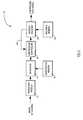
- FIG. 1is a schematic view of an image compression apparatus according to a first aspect of the invention
- FIG. 2is a schematic view of a preferred embodiment of the apparatus of FIG. 1, arranged to implement DCT-based image compression;
- FIG. 3is a first flow diagram illustrating the operation of a compression control module included in the apparatus of FIG. 2;
- FIG. 4is a second flow diagram illustrating the operation of the compression control module.
- FIG. 5is a schematic view of an architecture for the compression control module.
- FIG. 6is a representation of an 8 ⁇ 8 array of quantized frequency coefficients
- FIG. 7is a representation of a source image and constituent image components.
- the present inventionrelates to the compression, or encoding, of image data, specifically digitized image data.
- an imageis represented by a plurality of multi-bit pixels.
- the pixelsare grouped into arrays, or blocks, and are typically processed by a compression apparatus on a block-by-block basis.
- a colour imagecomprises a number of components, for example a red (R) component, a blue (B) component and a green (G) component, or two chrominance (U, V) components and a luminance (Y) component, whereas a grayscale image comprises a single component.
- The, or each, component of an imageis represented by blocks of pixels as described above and is processed by an image compression apparatus on a block-by-block basis.
- image compressionis to reduce the quantity or volume of image data to facilitate storage and transmission.
- FIG. 1there is shown, in schematic view, an image compression apparatus, generally indicated at 10 , according to a first aspect of the invention.
- the apparatus 10is arranged to receive an input image data signal comprising a plurality of image data blocks representing the or each component of a source image (not shown).
- Each image data blockcomprises an array of image data elements, or pixels, and each pixel comprises one or more bits of information.
- each pixelcomprises eight bits, and each image data block comprises an eight-by-eight array of pixels.
- the apparatus 10outputs a compressed data signal.
- the level of compression, or compression level, applied by the apparatus 10determines the volume of the compressed data signal compared to the to the volume of the image data signal for a given block or segment of the image data signal.
- the compression levelis expressed as a compression ratio i.e. a ratio of the volume of the compressed data signal to the volume of the image data signal.
- the apparatus 10includes a transform module 12 for transforming the image data signal from the spatial domain into the frequency domain.
- the transform module 12generates a respective array of frequency coefficients for each image data block.
- a quantization module, or quantizer 14is arranged to quantize each of the frequency coefficients in accordance with one or more quantization tables (not shown) which are held in a quantization memory 16 .
- the or each quantization tableholds a respective quantization coefficient for each frequency coefficient and the quantization module 14 divides (or multiplies as appropriate) each frequency coefficient with a respective quantization coefficient to generate a respective array of quantized frequency coefficients for each array of frequency coefficients.
- the quantization operationis performed using integer arithmetic so that each quantized frequency coefficient is rounded up or down to the nearest integer.
- one or more of the frequency coefficientsmay be set to zero.
- the or each frequency component of the source image represented by a frequency coefficient which is set to zerois effectively removed from the image data.
- Quantizationthus introduces losses in the image data such that the source image cannot precisely be reconstructed after quantization has occurred.
- the compression performed by the apparatus 10is known as a lossy compression.
- Lossy compression techniquesare not considered to be unduly problematic when compressing photographic images since a human observer's (not shown) perception of an image is not significantly impaired by the removal or reduction of certain frequency components of corresponding digitized image data. In particular, the removal or reduction of high frequency components does not significantly reduce the quality of an image to a human observer.
- a compression control module, or compression controller 18is provided to eliminate each non-zero frequency coefficient having a magnitude less than a threshold value. It is preferred that the compression controller 18 is located between the quantizer 14 and the entropy encoder 20 such that it operates on the quantized frequency coefficients produced by the quantizer 14 . It is possible, however, to arrange for the compression controller 18 to be located between the transform module 12 and the quantizer 14 such that it operates on the non-quantized frequency coefficients produced by the transform module 12 . In a preferred embodiment, the compression controller 18 eliminates, or removes, non-zero frequency components by setting them to zero. Advantageously, the operation of the compression controller 18 is selective in that the controller 18 is programmable to eliminate, or not to eliminate, those frequency coefficients falling below the threshold value.
- the compression controller 18is arranged to enable the threshold value to be programmable by a human operator (not shown).
- the compression controller 18is programmable with more than one different threshold value and is arranged to select one or other of the threshold values, thereby adapting the applied compression level, or ratio, depending on the volume of compressed image data being produced by the apparatus 10 , as is explained in more detail below.
- a preferred embodiment of the compression controller 18is described in detail with reference to FIGS. 2-5.
- the apparatus 10further includes an entropy encoding module, or entropy encoder 20 , arranged to generate a coded data element for each non-zero and non-eliminated frequency coefficient to produce a compressed data signal.
- the encoder 20generates each coded data element in accordance with one or more encoding tables held in an encoding memory 22 .
- the compressed data signalincludes the coded data elements together with one or more appended data elements relating to the structure of the compressed data signal, as is well known in the art.
- the apparatus 10is arranged to measure the volume of the compressed data signal and to compare the measured volume with a first target volume.
- a feedback communication line 24is provided between the entropy encoder 20 and the compression controller 18 .
- the entropy encoder 20measures the volume, in bytes for example, of each coded data element it produces and transmits this information to the compression controller 18 .
- the compression controller 18calculates the cumulative volume, in bytes for example, of coded data elements generated by the encoder 20 as a measure of the volume of the compressed data signal. It will be apparent that the measurement of the volume of each coded data element and the cumulative volume can both be performed by the entropy encoder 20 or the compression controller 18 , or in any other convenient manner.
- the target volumeis programmable by the operator and may be determined by, for example, the bandwidth of a communications link (not shown) across which the compressed data signal is to be transmitted. For example, typically the size of the digitized source image is known, as is the bandwidth of the communications link across which the compressed data signal is to be transmitted. It is therefore possible to calculate the desired compression ratio to be implemented by the compression apparatus 10 . Hence, for a given volume of image data blocks, the volume of coded data elements which can be generated without exceeding the desired compression ratio can be calculated.
- the target volumecan therefore be expressed as a volume of coded data elements, in bytes for example, per group of image data blocks, or of Minimum Coded Units (MCUs) where an MCU comprises one or more image data blocks depending on the composition of the digitized image data.
- MCUsMinimum Coded Units
- the target volumeis the same for each group of image data blocks or MCUs which make up a given source image although this need not necessarily be the case.
- the compression controller 18eliminates those non-zero frequency coefficients whose value is less than the current threshold value by setting the value of said non-zero coefficients to zero. If the measured volume of coded data elements exceeds the target volume, then the compression controller 18 may increase the threshold value so that frequency coefficients of larger magnitude are subsequently eliminated. In this way, the compression controller 18 reduces the volume of coded data elements subsequently generated by the entropy encoder 20 thereby increasing the compression ratio. If the measured volume of coded data elements is less than the first target volume, then the compression controller 18 may select to decrease the threshold value or not to eliminate any non-zero coefficients.
- the compression controller 18is programmable with more than one target volume, each specifying a respective target volume of coded data elements. This is advantageous in cases where, for example, an image is scanned more than once when being encoded or compressed.
- a first target volumemay be stipulated for the first scan, while a second target volume may be specified for the second scan, or for each subsequent scan, as required by the user.
- the elimination, or removal, of frequency coefficients which have a value i.e. magnitude, less than a given threshold valueis advantageous in that the compression controller 18 removes frequency components of the digitized image data according to their importance or significance in the source image, and irrespective of the actual frequency of the component. If the compression controller 18 is required to increase the level of compression, it does so at first by eliminating the frequency coefficients of smaller magnitude, which correspond to the less significant frequency components of the particular source image being compressed. If the compression controller 18 is required to further increase the level of compression, then it increases the threshold value so that it removes incrementally larger frequency coefficients (and therefore incrementally more important frequency components). Thus, the effect of increasing the compression ratio on the visual quality of the source image, when reconstructed, is minimized. In this context, it will be noted that the significance or importance of a frequency component is measured in terms of relative magnitude of that frequency component as opposed to the actual frequency of the component.
- the level of compression, or compression ratio, implemented by the apparatus 10 of the inventionis adaptive, or adaptable, in real time to the volume or quantity of compressed image data produced by the apparatus 10 .
- the compression technique implemented by the compression controller 18is adaptive to the frequency composition of the source image to be compressed in that frequency components are removed on the basis of their importance in the source image.
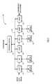
- the compression apparatus 110is arranged to implement sequential JPEG encoding as defined in the JPEG baseline standard (8-bit samples). It will be noted that the apparatus and method of the invention are also applicable for use with other compression standards, such as extended JPEG, and is not limited to an 8-bit sample size or to a particular number of Huffman or quantization tables.
- the compression apparatus 110is arranged to receive an image data signal comprising image data blocks each comprising an array (not illustrated) of eight-by-eight image data samples, or pixels, each pixel comprising eight data bits.
- a transform module in the form of a DCT transform module 112is arranged to transform, or decompose, each image data block into a corresponding eight-by-eight array (not shown) of frequency coefficients in accordance with conventional DCT algorithms (not shown).
- the DCT transformproduces one DC coefficient and sixty-three AC coefficients for each image data block.
- the transform module 112uses a two-dimensional transform architecture employing row-composition decomposition to decompose the operation into a two-stage, one-dimensional operation.
- a set of intermediate, one-dimensional resultsis produced and is stored in a transpose memory 113 .
- a skilled personwill appreciate that there are many conventional methods of performing a DCT transform which are also suitable. The present invention is not limited to the method outlined above. The preferred arrangement enables sustained one sample per clock cycle data processing.
- the DCT transform module 112produces frequency coefficients comprising eleven data bits.
- a quantization module or quantizer 114divides each of the sixty-four DCT frequency coefficients produced for each image data block by a respective quantization value, in conventional manner, to produce sixty-four quantized DCT frequency coefficients, each comprising eleven data bits.
- the quantization coefficientsare selectable from four quantization tables, each table being held in the quantization table memory 116 .
- the quantization tablesare determined by the operator and loaded into the quantization table memory 116 via a program control module 130 . The operator may also select which of the four quantization tables is to be used via the program control module 130 . It will be apparent that the number of qunatization tables used is not critical.
- the apparatus 110includes an entropy encoder comprising a Run Length Coding (RLC) module 121 , a Huffman encoding module 123 and a packing module 125 .
- the RLC module 121generates a respective first coded data element for each non-zero quantized frequency coefficient.
- Each coded data elementcomprises a Run component and a Size component, appended to the respective non-zero coefficient data.
- the Run componentrepresents the number of zero-value quantized frequency coefficients that were encountered between the current non-zero coefficient and the previous non-zero coefficient.
- the Size componentrepresents the number of data bits required to represent the current non-zero coefficient.
- the RLC moduleprocesses the quantized frequency coefficients in a zig-zag manner, i.e., that it processes the coefficients in ascending order of frequency. This tends to maximize the length of the runs of zero-value coefficients and, since a long run of zero-value coefficients is recorded in a single coded data element, the number of coded data elements produced is minimized.
- the RLC module 121reads the quantized frequency coefficients from a zig-zag memory 127 . This is achieved in conventional manner by the provision of re-ordering logic (not shown) in the RLC module 121 comprising a counter and an LUT which together generate the desired zig-zag address sequence.
- the zig-zag re-orderingneed not necessarily be performed at the RLC module 121 but may alternatively be performed beforehand at, for example, the quantizer 114 .
- the huffman encoder 123is arranged to receive the coded data elements produced by the RLC module 121 and to generate a respective second, or Huffman, coded data element for each RLC coded data element.
- the second coded data elementsare derived from a Huffman table held in the Huffman table memory 122 .
- Huffman encodingis intended to minimize the number of bits required to represent the RLC coded data elements.
- Each code in a Huffman tableis unique and corresponds with a particular combination of Run and Size components.
- the Huffman codesare variable in size and, advantageously, the more commonly occurring combinations of Run and Size are assigned to the shorter Huffman codes.
- Each Huffman coded data elementcomprises a respective Huffman code appended to respective frequency coefficient data.
- the Huffman table memoryis programmable with a plurality of Huffman tables, one or more table for the DC frequency coefficients, the remaining tables for the AC frequency coefficients. Preferably, there are four Huffman tables, two for the DC frequency coefficients and two for the AC frequency coefficients.
- the RLC module 121does not produce a Run component for the DC coefficients.
- the Huffman tablesmay be loaded by, and are, in use, selectable by, the operator via the program control module 130 .
- the Huffman encoder 123does not necessarily produce coded data elements contiguously—this depends on the nature of the source image data provided to the apparatus 110 .
- the packing module 125is arranged to receive the second coded data elements generated by the Huffman encoder 123 , join the coded data elements together, and then split them into units of, for example two-bytes.
- the packing module 125outputs the two-byte units serially to produce the compressed data signal.
- the compressed data signalfurther includes data structure information, in conventional manner as laid down by the JPEG baseline standard, to enable reconstruction. This is not described herein for reasons of clarity.
- a compression control module(CCM), or compression controller 118 , is preferably arranged between the quantizer 114 and the RLC module 121 .
- the compression controller 118is arranged to communicate with, in particular, the Huffman encoder 123 via communication line 119 (which serves as the communication line 24 depicted in FIG. 1 ).
- the compression controller 118counts the cumulative volume of coded data elements, in bytes for example, produced by the Huffman encoder 123 and compares the measured volume with a target volume.
- the target volumeis defined for a portion, or segment, of the source image rather than for the source image as a whole.
- the target volumeis defined in, for example, bytes per MCU, or per group of MCUs.
- the compression controller 118may take action to increase the compression level, or ratio, in order to reduce the volume of coded data elements produced for subsequent MCUs or groups of MCUs. Equally, if the measured volume is less than the target volume, the compression controller 118 may reduce the compression ratio.
- the compression controller 118is arranged to remove, or eliminate, any quantized frequency coefficients whose magnitude is less than a threshold value.
- the compression control module 118is provided with a plurality of threshold values, which for example are user programmable via the program control module 130 , and is arranged to select a respective one of said threshold values depending on the required change in compression ratio.
- the compression controller 118determines that the cumulative measured volume of coded data elements is still over target for the overall image, then the controller 118 selects a higher threshold value in order to remove a larger number of frequency coefficients in the image data blocks of subsequent image segments, thereby further increasing the compression ratio.
- the controller 118can select a lower threshold value so that fewer frequency coefficients are removed. Further, the controller 118 may select not to remove any frequency components if the volume of the coded data elements is on target.
- the compression ratio applied by the apparatus 110is thus adaptive in order to meet the predetermined overall target volume for the compressed image.
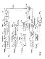
- FIG. 5is a schematic view of an architecture for the compression controller 118 .
- a first input signal NewBlkis asserted to indicate the arrival of each new, or successive, image data block from the quantizer 114 .
- the quantized frequency coefficients associated with each respective image data blockare received by the controller 118 as input signal DctCoeff.
- DctCoeffinput signal
- the quantized freqency coefficients associated with each data blockare processed by the Huffman encoder 123 .
- the Huffman encoder 123is arranged to generate a signal NumBytes each time it produces a Huffman coded data element.
- the Numbytes signalindicates the number of bytes contained within each respective Huffman coded data element produced, and is received by the compression controller 118 via communication line 119 .
- the Huffman encoderis arranged to generate a further signal BlkDone each time it finishes processing an image data block.
- the BlkDone signalis also received by the compression controller 118 via communication line 119 .
- the measurement of the volume of coded data elementsis conveniently performed for respective successive segments, or portions, of a source image, wherein each image segment comprises one or more MCU.
- An MCUmay comprise one or more image data block depending on the strucure of the source image.
- the compression controller 118is provided with two variable paramenters namely, NumBlksMcu, which indicates the number of image data blocks per MCU in the source image to be processed, and NMcu, which indicates the number of MCUs in each image segment.
- NMcuis selectable by the operator and provided to the compression controller 118 via the program control module 130 .
- NumBlksMcuis determined by the structure of the source image to be processed and is also provided to the compression controller 118 via the program control module 130 . It will be apparent that the controller 118 need not necessarily operate on groups of one of more MCUs—the image data may be operated on in segments in any convenient manner.
- the compression controller 118is also provided with one or more target volumes for each image segment.
- two target volumesare provided, one for the first scan of the source, the other for all subsequent scans of the image.
- the target volumesare determined by the operator as described above and are provided to the compression controller 118 via the program control module 130 .
- the value of the target volumeis represented in FIG. 5 by Target.
- the compression controller 118is further provided with one or more threshold values.
- a plurality of threshold values of increasing magnitudeare defined and are each associated with a respective control action level, L.
- the respective associated threshold valueincreases, preferably in even increments, and the controller 118 is arranged to remove all quantized frequency coefficients on or below the threshold value of the selected level.
- coefficients 1 - 15normally represent the lower frequency components of the source image which, as described above, are more important to an observer's perception of an image than the higher frequency components represented by coefficients 16 - 31 or 32 - 63 .
- the threshold value for application to coefficients 1 - 15is advantageously set lower than the threshold value for coefficients 16 - 31 , which in turn is advantageously lower than the threshold value for coefficients 32 - 63 .
- The, or each, threshold value for the, or each, control action levelis selectable by the operator and provided to the compression controller 118 via the program control module 130 .
- FIG. 3is a flow chart illustrating the process whereby the compression controller 118 of the preferred embodiment determines which control action level, L, to apply.
- Modules 302 , 303 and 304define the period over which the volume of coded data elements produced by the Huffman encoder 123 is measured. In the present example, a respective volume measurement is performed for sucessive source image segments, where the size of an image segment is defined by NMcu.
- the controller 118determines when a complete image data block is processed by the Huffman enocder 123 (via the BlkDone signal).
- the controller 118counts the number of processed image data blocks and updates a count variable HuffBlkCnt.
- the controller 118determines when an image segment is processed i.e. when HuffBlkCnt is equal to NMcu.
- the controller 118counts, or measures, the volume of coded data elements produced by the Huffman encoder 123 and records the volume accumulated for the current image segment as variable Sum.
- the controller 118resets HuffBlkCnt and calculates the difference between the measured value for Sum and the target volume Target for said current image segment.
- the controller 118also sums the respective values of Spare for each successive image segment to produce CumSpare.
- the controllerdetermines whether CumSpare is positive or negative. If CumSpare is negative, this is indicative that the current level of compression may not result in the target volume for the overall image being met and that, accordingly, an increase in the control action level L may be required. The controller 118 then progresses to module 307 where it makes a further determination as to whether an increase in the control action level L is required. Specifically, the controller 118 checks whether the current value for CumSpare is less than the previous value for CumSpare (indicated in FIG. 3 as PrevCumSpare) i.e. whether or not the current value of Spare is negative. The controller 118 also checks whether the current action level L is less than the maximum action level (which is 7 in the present example).
- the controllerselects a higher control action level (module 308 ) thereby increasing the applied compression level in order to meet the target volume for the overall compressed image, otherwise the controller 118 leaves the control action level unchanged.
- the controller 118checks whether the current value for CumSpare is greater than the previous value for CumSpare (indicated in FIG. 3 as PrevCumSpare) i.e. whether or not the current value of Spare is positive. The controller 118 also checks whether the current action level L is greater than the minimum action level (which is 0 in the present example).
- the controllerselects a lower control action level (module 310 ) thereby decreasing the applied compression level, otherwise the controller 118 leaves the control action level unchanged.
- control action level Lis not limiting.
- a skilled personwill appreciate that other criteria for increasing or decreasing the control action level L may be employed.
- a cruder version of the compression controllermay select the control action level L solely on the basis of whether the Spare value is positive or negative, or whether the CumSpare value is increasing or decreasing.
- the process of FIG. 3is preferred as it performs a more sophisticated analysis of whether or not the target volume for the overall compressed image will be met and therefore produces more accurate results.
- FIG. 4is a flow chart illustrating how the compression controller 118 applies a newly selected control action level L.
- Lthe corresponding threshold value(s) are applied to the next, and all subsequent, image data blocks received by the compression controller 118 until L changes again.
- the flow of data through the apparatus 110is not necessarily uniform, and is therefore not necessarily predictable, as it is dependent on how the source image data is received by the apparauts 110 . It is therefore not possible to say when the new value for L will be available. It is however possible to say that the new value of L will be available within a given number of image data blocks after the group of MCUs, which correspond to the current image segment, have entered the compression controller 118 .
- LatencySaid given number of image data blocks is hereinafter referred to as Latency and the controller is preferably arranged to apply a newly calculated control action level L Latency image data blocks after the end of the current image segment.
- the packing module 125advantageously has an output enable signal which can be used to stall, or delay, the data output. If this signal is de-asserted, then this causes data to build up in the RLC and Huffman modules 121 , 123 . The space allowed for this build-up means that input data can still be processed continuously as long as the stall is not too long.
- the amount of data that can be storedis fixed, but represents a variable number of data blocks depending on the compression ratio. This number of blocks has an upper limit, which also corresponds to Latency. In the present example Latency is set equal to 6. This arrangement allows the operation of the apparatus 110 to be more predictable and enables a bit-accurate model, for example a C-model, to be produced.
- Module 401represents the initial state after reset.
- the controller 118detects the arrival of a new image data block from the quantiser 114 (the new block arrival being indicated by the signal NewBlk, FIG. 5 ).
- the controller 118increments a variable NewBlkCnt for each new image data block received.
- the controllerdetermines when the end of the current image segment occurs. Then, the controller 118 counts, or waits for, the arrival of a further number (Latency) of image data blocks before proceeding to Module 405 .
- the controllerresets NewBlkCnt and sets the current control action level L to the newly calculated value.
- the compression controller 118measures the volume of coded data elements produced for successive image segments, wherein each segment comprises a group of one or more MCUs, and compares the measured volume against a target volume for the image segment. Further, the controller 118 calculates the required control action level L after each image segment is processed. It is preferred that the group comprises more than one MCU in order to smooth out the operation of the controller 118 by averaging the density of the image data over the group size. Thus, if a particular image data block or MCU contains a particularly high, or low, information content, the controller 118 does not necessarily respond by increasing, or decreasing respectively, the control action level L—the effect of such an extreme data block or MCU is averaged over the group size.
- the controller 118may react too quickly. On the other hand, if the group size is too large, the controller 118 may not react quickly enough. The result in either case may be that the target volume for the overall image is not be met or that portions of the source image are compressed at an unecessarily high level.
- the compression controller 118is arranged to receive each of the required parameters NumBlksMcu, NMcu, Latent, and Target, as indicated in the Figure, from the program control module 130 .
- the control action level Lis initially set to 0 and this value is recorded in register 510 (designated Curr_L in FIG. 5 ).
- each control action level Lis associated with three respective threshold values, as explained above, and each respective set of three threshold values is provided to the controller 118 by the program control module 130 and stored in a Look-up table (LUT) an LUT 513 (designated Actions LUT in FIG. 5 ).
- the compression control apparatus 118performs the following operations. It receives and stores the parameters as outlined above; it counts the number of MCUs that pass through it; it counts the number of MCUs processed by the Huffman encoder 123 ; it counts the volume (in bytes) of coded data elements produced by the Huffman encoder 123 ; it calculates an appropriate value for the control action level L; and it removes all quantized frequency coefficients of magnitude less than that specified by the current control action level L.
- NewBlkEach time a new image data block is input to the compression controller 118 by the quantizer 114 , it is accompanied by the signal NewBlk. Each time the NewBlk signal is asserted, the value of NewBlkCnt, which is stored in register 501 , is incremented. The value of NewBlkCnt is compared with the value of NumBlksMcu at comparator module 517 . When NewBlkCnt equals NumBlksMcu, NewBlkCnt is re-set to zero and the value of a variable NewMcuCnt, which is stored in register 502 , is incremented.
- NewMcuCntis a measure of how many MCUs have been received by the compression controller 118 .
- Comparator module 518compares the value of NewMcuCnt with NMcu. When NewMcuCnt equals NMcu, the comparator module 518 signals to a register 503 that a complete image segment has been received. Register 503 holds a variable LatCnt. Each time the comparator module 518 indicates that a complete image segment has been received, the variable LatCnt is incremented for each subsequent new image data block received. To this end, the NewBlk signal is also fed directly to register 503 . Comparator module 519 compares the value of LatCnt with the stored value for Latency.
- Huffman encoder 123Each time the Huffman encoder 123 finishes encoding an image data block, it asserts the BlkDone signal and the value of HuffMcuCnt, which is held in register 504 , is incremented. Comparator module 520 compares the value of HuffBlkCnt with the value of NumBlksMcu. When HuffBlkCnt equals NumBlksMcu, the value of variable HuffMcuCnt, which is stored in register 505 , is incremented by a signal from the comparator module 520 . The variable HuffMcuCnt is representative of the number of MCUs processed by the Huffman encoder 123 .
- Comparator module 521compares the value of HuffMcuCnt with the known value of NMcu. When the value of HuffMcuCnt reaches the value ATMcu, HuffMcuCnt is re-set to zero and a signal HuffMcuEq is asserted for one cycle.
- the Huffman encoder 123is arranged to calculate or count the number of data bits it produces when generating coded data elements i.e. to calculate the volume of coded data elements produced.
- the Huffman encoder 123is arranged to provide said volume in bytes and so the number of data bits counted is divided by eight, with any remainder data bits being stored for use in subsequent calculations.
- every time the Huffman encoder 123 produces a coded data elementit calculates the number of bits produced and adds this to the number of remainder bits left over from previous calculations.
- the calculated volumeis divided by eight to convert to bytes and output as signal NumBytes.
- NumBytesis set to zero.
- the NumBytes signalis received by the compression controller 118 as indicated in FIG. 5 .
- Register 506stores a value for Spare which is initially set equal to the target volume for an image segment. The received value of NumBytes is subtracted from the value of Spare by subtrator module 522 .
- CumSpare Register 507holds a value CumSpare to which the value of Spare is added each time signal HuffMcuEq is asserted.
- each control action level Lis associated with three respective threshold values, each for application to a respective set of quantized frequency coefficients produced for each image data block, the compression controller 118 must calculate the relative position of each quantized frequency coefficient within its respective array.
- FIG. 6is a representation of an 8 ⁇ 8 array of quantized frequency coefficients wherein the arrows indicate the input order of the coefficients.
- coefficients 0 to 15are designated as being in region zero of the array
- coefficients 16 to 31are designated as being in region 1 of the array
- coefficients 32 to 63are designated as being in region 2 .
- a respective threshold valueis applied to the coefficients according to the region in which they lie.
- the quantized frequency coefficientsare input to the compression controller 118 (via signal DctCoeff) they are each accompanied by a DctValid signal. Each time DctValid is asserted, the value of a variable NumCoeff, which is stored in Register 511 , is incremented. NumCoeff is supplied to a spectral LUT 512 which determines which region of the frequency coefficient array, or spectrum, a given frequency coefficient is from.
- the Spectral LUT 512supplies this information to the Actions LUT 513 , which also receives the current value of control action level L from Register 510 .
- the actions LUT 513is thus able to calculate the threshold value which is to be applied to the current quantized frequency coefficient as received in signal DctCoeff.
- a size calculation module 514is arranged to receive the incoming quantized frequency coefficient in signal DctCoeff and calculates the size of each coefficient in accordance with, for example, Table 1 below.
- the calculated coefficient sizeis fed to comparator 523 which also receives the relevant threshold value from the actions LUT 513 . If the calculated coefficient size is equal to or less than the relevant threshold value, then signal Eliminate is asserted.
- a multiplexor 516is arranged to receive the signal DctCoeff as one input, and the value zero as a second input.
- the signal Eliminateserves as the control signal for the multiplexor 516 such that, when Eliminate is asserted, the zero input is selected at the output ADct of the multiplexor 516 , otherwise ADct takes the value of the current quantized frequency coefficient as provided by DctCoeff.
- the compression troller 118effectively removes or eliminates the current quantized frequency coefficient.
- the size of a source image 700is 256 bytes ⁇ 256 bytes and comprises three colour components 702 , 704 and 706 .
- the horizontal sampling factorsare 2 , 1 , 1 for components 702 , 704 and 706 respectively and the respective vertical sampling factors are 1 , 1 , 1 (see components 702 ′, 704 ′, 706 ′ in FIG. 7 ).
- NMcuis set at 10 and the desired compression ratio is assumed to 20:1.
- the source image sizeis first calculated, assuming 8-byte samples per component.
- each MCUis comprised of two 8 ⁇ 8 blocks from the first component 702 , one 8 ⁇ 8 block from the second component 704 , and one 8 ⁇ 8 block from the third component 706 .
- the total number of MCUs in the source image 700is calculated as 512 .
- the invention described aboverelates to an image compression apparatus 10 , 110 and in particular to an image compression apparatus for implementing the JPEG baseline standard.
- a conventional decompression apparatus(not shown) is required.
Landscapes
- Engineering & Computer Science (AREA)
- Multimedia (AREA)
- Signal Processing (AREA)
- Computing Systems (AREA)
- Theoretical Computer Science (AREA)
- Compression Or Coding Systems Of Tv Signals (AREA)
- Compression, Expansion, Code Conversion, And Decoders (AREA)
- Compression Of Band Width Or Redundancy In Fax (AREA)
Abstract
Description
| TABLE 1 | |||
| Amplitude | |||
| 0 | 0 | ||
| 1 | −1, | 1 | ||
| 2 | −3, −2, | 2, 3 | ||
| 3 | −7, . . ., −4, | 4, . . ., 7 | ||
| 4 | −15, . . ., −8, | 8, . . ., 15 | ||
| 5 | −31, . . ., −16, | 16, . . ., 31 | ||
| 6 | −63, . . ., −32, | 32, . . ., 63 | ||
| 7 | −127, . . ., −64, | 64, . . ., 127 | ||
| 8 | −255, . . ., −128, | 128, . . ., 255 | ||
| 9 | −511, . . ., −256, | 256, . . ., 511 | ||
| 10 | −1023, . . ., −512, | 512, . . ., 1023 | ||
| 11 | −2047, . . ., −1024, | 1024, . . ., 2047 | ||

Claims (16)
Priority Applications (2)
| Application Number | Priority Date | Filing Date | Title |
|---|---|---|---|
| US09/588,266US6724817B1 (en) | 2000-06-05 | 2000-06-05 | Adaptive image data compression |
| EP01113717AEP1162826A3 (en) | 2000-06-05 | 2001-06-05 | Adaptive image data compression |
Applications Claiming Priority (1)
| Application Number | Priority Date | Filing Date | Title |
|---|---|---|---|
| US09/588,266US6724817B1 (en) | 2000-06-05 | 2000-06-05 | Adaptive image data compression |
Publications (1)
| Publication Number | Publication Date |
|---|---|
| US6724817B1true US6724817B1 (en) | 2004-04-20 |
Family
ID=24353160
Family Applications (1)
| Application Number | Title | Priority Date | Filing Date |
|---|---|---|---|
| US09/588,266Expired - LifetimeUS6724817B1 (en) | 2000-06-05 | 2000-06-05 | Adaptive image data compression |
Country Status (2)
| Country | Link |
|---|---|
| US (1) | US6724817B1 (en) |
| EP (1) | EP1162826A3 (en) |
Cited By (53)
| Publication number | Priority date | Publication date | Assignee | Title |
|---|---|---|---|---|
| US20020141653A1 (en)* | 2001-03-28 | 2002-10-03 | Leonardo Estevez | Image compression |
| US20030076301A1 (en)* | 2001-10-22 | 2003-04-24 | Apple Computer, Inc. | Method and apparatus for accelerated scrolling |
| US20030076303A1 (en)* | 2001-10-22 | 2003-04-24 | Apple Computers, Inc. | Mouse having a rotary dial |
| US20030076306A1 (en)* | 2001-10-22 | 2003-04-24 | Zadesky Stephen Paul | Touch pad handheld device |
| US20030091242A1 (en)* | 2001-10-23 | 2003-05-15 | Ramakrishna Kakarala | Signaling adaptive-quantization matrices in JPEG using end-of-block codes |
| US20030095096A1 (en)* | 2001-10-22 | 2003-05-22 | Apple Computer, Inc. | Method and apparatus for use of rotational user inputs |
| US20030103074A1 (en)* | 2001-12-04 | 2003-06-05 | Koninklijke Philips Electronics N.V. | Methods for multimedia content repurposing |
| US20030224734A1 (en)* | 2002-05-20 | 2003-12-04 | Fujitsu Limited | Data compression program, data compression method, and data compression device |
| US20040035876A1 (en)* | 2002-08-23 | 2004-02-26 | Pfizer Inc | Apparatus for dispensing articles |
| US20040046741A1 (en)* | 2002-09-09 | 2004-03-11 | Apple Computer, Inc. | Mouse having an optically-based scrolling feature |
| US20050052425A1 (en)* | 2003-08-18 | 2005-03-10 | Zadesky Stephen Paul | Movable touch pad with added functionality |
| US20050110768A1 (en)* | 2003-11-25 | 2005-05-26 | Greg Marriott | Touch pad for handheld device |
| US20050175091A1 (en)* | 2004-02-06 | 2005-08-11 | Atul Puri | Rate and quality controller for H.264/AVC video coder and scene analyzer therefor |
| US20050175092A1 (en)* | 2004-02-06 | 2005-08-11 | Atul Puri | H.264/AVC coder incorporating rate and quality controller |
| US7119792B1 (en) | 2000-01-12 | 2006-10-10 | Apple Computer, Inc. | Cursor control device having an integral top member |
| US20060274042A1 (en)* | 2005-06-03 | 2006-12-07 | Apple Computer, Inc. | Mouse with improved input mechanisms |
| US7233318B1 (en) | 2002-03-13 | 2007-06-19 | Apple Inc. | Multi-button mouse |
| US20070242057A1 (en)* | 2002-02-25 | 2007-10-18 | Apple Inc. | Touch pad for handheld device |
| US20080036734A1 (en)* | 2005-09-06 | 2008-02-14 | Apple Computer, Inc. | Scrolling input arrangements using capacitive sensors on a flexible membrane |
| US20080297478A1 (en)* | 2003-09-02 | 2008-12-04 | Steve Hotelling | Ambidextrous Mouse |
| US7492820B2 (en) | 2004-02-06 | 2009-02-17 | Apple Inc. | Rate control for video coder employing adaptive linear regression bits modeling |
| US20090245674A1 (en)* | 2008-03-27 | 2009-10-01 | Megachips Corporation | Image processor |
| EP2160036A2 (en) | 2008-09-01 | 2010-03-03 | Fundación Cetena | Method of bit rate control in digital video compression systems based on MJPEG |
| US7795553B2 (en) | 2006-09-11 | 2010-09-14 | Apple Inc. | Hybrid button |
| US7880729B2 (en) | 2005-10-11 | 2011-02-01 | Apple Inc. | Center button isolation ring |
| US7910843B2 (en) | 2007-09-04 | 2011-03-22 | Apple Inc. | Compact input device |
| US7932897B2 (en) | 2004-08-16 | 2011-04-26 | Apple Inc. | Method of increasing the spatial resolution of touch sensitive devices |
| US8022935B2 (en) | 2006-07-06 | 2011-09-20 | Apple Inc. | Capacitance sensing electrode with integrated I/O mechanism |
| US8059099B2 (en) | 2006-06-02 | 2011-11-15 | Apple Inc. | Techniques for interactive input to portable electronic devices |
| US8077147B2 (en) | 2005-12-30 | 2011-12-13 | Apple Inc. | Mouse with optical sensing surface |
| US8125461B2 (en) | 2008-01-11 | 2012-02-28 | Apple Inc. | Dynamic input graphic display |
| US8274479B2 (en) | 2006-10-11 | 2012-09-25 | Apple Inc. | Gimballed scroll wheel |
| US8395590B2 (en) | 2008-12-17 | 2013-03-12 | Apple Inc. | Integrated contact switch and touch sensor elements |
| US8416198B2 (en) | 2007-12-03 | 2013-04-09 | Apple Inc. | Multi-dimensional scroll wheel |
| US8482530B2 (en) | 2006-11-13 | 2013-07-09 | Apple Inc. | Method of capacitively sensing finger position |
| US8514185B2 (en) | 2006-07-06 | 2013-08-20 | Apple Inc. | Mutual capacitance touch sensing device |
| US8537132B2 (en) | 2005-12-30 | 2013-09-17 | Apple Inc. | Illuminated touchpad |
| US8683378B2 (en) | 2007-09-04 | 2014-03-25 | Apple Inc. | Scrolling techniques for user interfaces |
| US8743060B2 (en) | 2006-07-06 | 2014-06-03 | Apple Inc. | Mutual capacitance touch sensing device |
| US8816967B2 (en) | 2008-09-25 | 2014-08-26 | Apple Inc. | Capacitive sensor having electrodes arranged on the substrate and the flex circuit |
| US8820133B2 (en) | 2008-02-01 | 2014-09-02 | Apple Inc. | Co-extruded materials and methods |
| US8872771B2 (en) | 2009-07-07 | 2014-10-28 | Apple Inc. | Touch sensing device having conductive nodes |
| US9047009B2 (en) | 2005-03-04 | 2015-06-02 | Apple Inc. | Electronic device having display and surrounding touch sensitive bezel for user interface and control |
| US20150189288A1 (en)* | 2013-12-26 | 2015-07-02 | Megachips Corporation | Image processor |
| US20150256843A1 (en)* | 2014-03-07 | 2015-09-10 | Steven Roskowski | Adaptive Security Camera Image Compression Apparatus and Method of Operation |
| US9354751B2 (en) | 2009-05-15 | 2016-05-31 | Apple Inc. | Input device with optimized capacitive sensing |
| US9367151B2 (en) | 2005-12-30 | 2016-06-14 | Apple Inc. | Touch pad with symbols based on mode |
| US9454256B2 (en) | 2008-03-14 | 2016-09-27 | Apple Inc. | Sensor configurations of an input device that are switchable based on mode |
| US9654104B2 (en) | 2007-07-17 | 2017-05-16 | Apple Inc. | Resistive force sensor with capacitive discrimination |
| US10089360B2 (en) | 2015-06-19 | 2018-10-02 | Western Digital Technologies, Inc. | Apparatus and method for single pass entropy detection on data transfer |
| US10152389B2 (en) | 2015-06-19 | 2018-12-11 | Western Digital Technologies, Inc. | Apparatus and method for inline compression and deduplication |
| US11275405B2 (en) | 2005-03-04 | 2022-03-15 | Apple Inc. | Multi-functional hand-held device |
| US20230319279A1 (en)* | 2020-12-09 | 2023-10-05 | Huawei Technologies Co., Ltd. | Media Packetization For Network Qualitative Communication |
Families Citing this family (4)
| Publication number | Priority date | Publication date | Assignee | Title |
|---|---|---|---|---|
| EP1879401A4 (en)* | 2005-05-03 | 2012-03-28 | Panasonic Corp | DYNAMIC IMAGE ENCODING METHOD, DYNAMIC IMAGE DECODING METHOD, AND DEVICE THEREFOR |
| EP1720356A1 (en)* | 2005-05-03 | 2006-11-08 | Matsushita Electric Industrial Co., Ltd. | A frequency selective video compression |
| US7460725B2 (en) | 2006-11-09 | 2008-12-02 | Calista Technologies, Inc. | System and method for effectively encoding and decoding electronic information |
| CN107589910A (en)* | 2017-09-01 | 2018-01-16 | 厦门集微科技有限公司 | The method and system of the high in the clouds data management of user's custom strategies |
Citations (9)
| Publication number | Priority date | Publication date | Assignee | Title |
|---|---|---|---|---|
| US5126842A (en)* | 1989-12-30 | 1992-06-30 | Sony Corporation | Video signal encoding method with a substantially constant amount of transform data per transmission unit block |
| US5333212A (en) | 1991-03-04 | 1994-07-26 | Storm Technology | Image compression technique with regionally selective compression ratio |
| US5892548A (en) | 1996-04-30 | 1999-04-06 | Daewoo Electronics Co., Ltd. | Adaptive quantizer with modification of high frequency coefficients |
| WO2000018130A1 (en) | 1998-09-18 | 2000-03-30 | Sarnoff Corporation | Treating non-zero quantized transform coefficients as zeros during video compression processing |
| US6111913A (en)* | 1997-05-20 | 2000-08-29 | International Business Machines Corporation | Macroblock bit regulation schemes for video encoder |
| US6160846A (en)* | 1995-10-25 | 2000-12-12 | Sarnoff Corporation | Apparatus and method for optimizing the rate control in a coding system |
| US6173012B1 (en)* | 1996-04-25 | 2001-01-09 | Matsushita Electric Industrial Co., Ltd. | Moving picture encoding apparatus and method |
| US6215820B1 (en)* | 1998-10-12 | 2001-04-10 | Stmicroelectronics S.R.L. | Constant bit-rate control in a video coder by way of pre-analysis of a slice of the pictures |
| US6373895B2 (en)* | 1995-10-30 | 2002-04-16 | Sony Corporation | Video data compression with trial encoder |
- 2000
- 2000-06-05USUS09/588,266patent/US6724817B1/ennot_activeExpired - Lifetime
- 2001
- 2001-06-05EPEP01113717Apatent/EP1162826A3/ennot_activeWithdrawn
Patent Citations (10)
| Publication number | Priority date | Publication date | Assignee | Title |
|---|---|---|---|---|
| US5126842A (en)* | 1989-12-30 | 1992-06-30 | Sony Corporation | Video signal encoding method with a substantially constant amount of transform data per transmission unit block |
| US5333212A (en) | 1991-03-04 | 1994-07-26 | Storm Technology | Image compression technique with regionally selective compression ratio |
| US6160846A (en)* | 1995-10-25 | 2000-12-12 | Sarnoff Corporation | Apparatus and method for optimizing the rate control in a coding system |
| US6373895B2 (en)* | 1995-10-30 | 2002-04-16 | Sony Corporation | Video data compression with trial encoder |
| US6173012B1 (en)* | 1996-04-25 | 2001-01-09 | Matsushita Electric Industrial Co., Ltd. | Moving picture encoding apparatus and method |
| US5892548A (en) | 1996-04-30 | 1999-04-06 | Daewoo Electronics Co., Ltd. | Adaptive quantizer with modification of high frequency coefficients |
| US6111913A (en)* | 1997-05-20 | 2000-08-29 | International Business Machines Corporation | Macroblock bit regulation schemes for video encoder |
| WO2000018130A1 (en) | 1998-09-18 | 2000-03-30 | Sarnoff Corporation | Treating non-zero quantized transform coefficients as zeros during video compression processing |
| US6263021B1 (en)* | 1998-09-18 | 2001-07-17 | Sarnoff Corporation | Treating non-zero quantized transform coefficients as zeros during video compression processing |
| US6215820B1 (en)* | 1998-10-12 | 2001-04-10 | Stmicroelectronics S.R.L. | Constant bit-rate control in a video coder by way of pre-analysis of a slice of the pictures |
Non-Patent Citations (2)
| Title |
|---|
| Copy of European Search Report for EP 01 11 3717. |
| Paper, "Rate-Distortion Optimas Fast Thresholding With Complete JPEG/MPEG Decoder Compatibility", dated Sep. 1994, by Kannan Ramchandran and Martin Vetterli. |
Cited By (119)
| Publication number | Priority date | Publication date | Assignee | Title |
|---|---|---|---|---|
| US7119792B1 (en) | 2000-01-12 | 2006-10-10 | Apple Computer, Inc. | Cursor control device having an integral top member |
| US20020141653A1 (en)* | 2001-03-28 | 2002-10-03 | Leonardo Estevez | Image compression |
| US7123772B2 (en)* | 2001-03-28 | 2006-10-17 | Texas Instruments Incorporated | Image compression by differences within a strip |
| US7710393B2 (en) | 2001-10-22 | 2010-05-04 | Apple Inc. | Method and apparatus for accelerated scrolling |
| US7710409B2 (en) | 2001-10-22 | 2010-05-04 | Apple Inc. | Method and apparatus for use of rotational user inputs |
| US20030095096A1 (en)* | 2001-10-22 | 2003-05-22 | Apple Computer, Inc. | Method and apparatus for use of rotational user inputs |
| US7312785B2 (en)* | 2001-10-22 | 2007-12-25 | Apple Inc. | Method and apparatus for accelerated scrolling |
| US9977518B2 (en) | 2001-10-22 | 2018-05-22 | Apple Inc. | Scrolling based on rotational movement |
| US9009626B2 (en) | 2001-10-22 | 2015-04-14 | Apple Inc. | Method and apparatus for accelerated scrolling |
| US8952886B2 (en) | 2001-10-22 | 2015-02-10 | Apple Inc. | Method and apparatus for accelerated scrolling |
| US20070080938A1 (en)* | 2001-10-22 | 2007-04-12 | Apple Computer, Inc. | Method and apparatus for use of rotational user inputs |
| US7710394B2 (en) | 2001-10-22 | 2010-05-04 | Apple Inc. | Method and apparatus for use of rotational user inputs |
| US20070080936A1 (en)* | 2001-10-22 | 2007-04-12 | Apple Computer, Inc. | Method and apparatus for accelerated scrolling |
| US7345671B2 (en) | 2001-10-22 | 2008-03-18 | Apple Inc. | Method and apparatus for use of rotational user inputs |
| US7046230B2 (en) | 2001-10-22 | 2006-05-16 | Apple Computer, Inc. | Touch pad handheld device |
| US7084856B2 (en) | 2001-10-22 | 2006-08-01 | Apple Computer, Inc. | Mouse having a rotary dial |
| US20030076301A1 (en)* | 2001-10-22 | 2003-04-24 | Apple Computer, Inc. | Method and apparatus for accelerated scrolling |
| US20030076306A1 (en)* | 2001-10-22 | 2003-04-24 | Zadesky Stephen Paul | Touch pad handheld device |
| US20030076303A1 (en)* | 2001-10-22 | 2003-04-24 | Apple Computers, Inc. | Mouse having a rotary dial |
| US7092578B2 (en)* | 2001-10-23 | 2006-08-15 | Agilent Technologies, Inc. | Signaling adaptive-quantization matrices in JPEG using end-of-block codes |
| US20030091242A1 (en)* | 2001-10-23 | 2003-05-15 | Ramakrishna Kakarala | Signaling adaptive-quantization matrices in JPEG using end-of-block codes |
| US7305618B2 (en)* | 2001-12-04 | 2007-12-04 | Koninklijke Philips Electronics N.V. | Methods for multimedia content repurposing |
| US20030103074A1 (en)* | 2001-12-04 | 2003-06-05 | Koninklijke Philips Electronics N.V. | Methods for multimedia content repurposing |
| US7333092B2 (en) | 2002-02-25 | 2008-02-19 | Apple Computer, Inc. | Touch pad for handheld device |
| US8446370B2 (en) | 2002-02-25 | 2013-05-21 | Apple Inc. | Touch pad for handheld device |
| US10353565B2 (en) | 2002-02-25 | 2019-07-16 | Apple Inc. | Input apparatus and button arrangement for handheld device |
| US20070242057A1 (en)* | 2002-02-25 | 2007-10-18 | Apple Inc. | Touch pad for handheld device |
| US7535458B2 (en) | 2002-03-13 | 2009-05-19 | Apple Inc. | Multi-button mouse |
| US9261984B2 (en) | 2002-03-13 | 2016-02-16 | Apple Inc. | Multi-button mouse |
| US20070211033A1 (en)* | 2002-03-13 | 2007-09-13 | Apple Inc. | Multi-button mouse |
| US8243018B2 (en) | 2002-03-13 | 2012-08-14 | Apple Inc. | Multi-button mouse |
| US20090207136A1 (en)* | 2002-03-13 | 2009-08-20 | Apple Inc. | Multi-button mouse |
| US7233318B1 (en) | 2002-03-13 | 2007-06-19 | Apple Inc. | Multi-button mouse |
| US7451237B2 (en)* | 2002-05-20 | 2008-11-11 | Fujitsu Limited | Data compression program, data compression method, and data compression device |
| US20030224734A1 (en)* | 2002-05-20 | 2003-12-04 | Fujitsu Limited | Data compression program, data compression method, and data compression device |
| US9983742B2 (en) | 2002-07-01 | 2018-05-29 | Apple Inc. | Electronic device having display and surrounding touch sensitive bezel for user interface and control |
| US20040035876A1 (en)* | 2002-08-23 | 2004-02-26 | Pfizer Inc | Apparatus for dispensing articles |
| US20040046741A1 (en)* | 2002-09-09 | 2004-03-11 | Apple Computer, Inc. | Mouse having an optically-based scrolling feature |
| US8314773B2 (en) | 2002-09-09 | 2012-11-20 | Apple Inc. | Mouse having an optically-based scrolling feature |
| US20080150898A1 (en)* | 2002-09-09 | 2008-06-26 | Apple, Inc. | Mouse having an optically-based scrolling feature |
| US7358963B2 (en) | 2002-09-09 | 2008-04-15 | Apple Inc. | Mouse having an optically-based scrolling feature |
| US8749493B2 (en) | 2003-08-18 | 2014-06-10 | Apple Inc. | Movable touch pad with added functionality |
| US7499040B2 (en) | 2003-08-18 | 2009-03-03 | Apple Inc. | Movable touch pad with added functionality |
| US20050052425A1 (en)* | 2003-08-18 | 2005-03-10 | Zadesky Stephen Paul | Movable touch pad with added functionality |
| US9785258B2 (en) | 2003-09-02 | 2017-10-10 | Apple Inc. | Ambidextrous mouse |
| US20080297476A1 (en)* | 2003-09-02 | 2008-12-04 | Steve Hotelling | Ambidextrous Mouse |
| US20080297477A1 (en)* | 2003-09-02 | 2008-12-04 | Steve Hotelling | Ambidextrous Mouse |
| US10156914B2 (en) | 2003-09-02 | 2018-12-18 | Apple Inc. | Ambidextrous mouse |
| US8704769B2 (en) | 2003-09-02 | 2014-04-22 | Apple Inc. | Ambidextrous mouse |
| US8704770B2 (en) | 2003-09-02 | 2014-04-22 | Apple Inc. | Ambidextrous mouse |
| US7808479B1 (en) | 2003-09-02 | 2010-10-05 | Apple Inc. | Ambidextrous mouse |
| US20080297478A1 (en)* | 2003-09-02 | 2008-12-04 | Steve Hotelling | Ambidextrous Mouse |
| US8537115B2 (en) | 2003-09-02 | 2013-09-17 | Apple Inc. | Ambidextrous mouse |
| US10474251B2 (en) | 2003-09-02 | 2019-11-12 | Apple Inc. | Ambidextrous mouse |
| US8552990B2 (en) | 2003-11-25 | 2013-10-08 | Apple Inc. | Touch pad for handheld device |
| US20050110768A1 (en)* | 2003-11-25 | 2005-05-26 | Greg Marriott | Touch pad for handheld device |
| US8933890B2 (en) | 2003-11-25 | 2015-01-13 | Apple Inc. | Techniques for interactive input to portable electronic devices |
| US7495659B2 (en) | 2003-11-25 | 2009-02-24 | Apple Inc. | Touch pad for handheld device |
| US7986731B2 (en)* | 2004-02-06 | 2011-07-26 | Apple Inc. | H.264/AVC coder incorporating rate and quality controller |
| US8036267B2 (en) | 2004-02-06 | 2011-10-11 | Apple, Inc. | Rate control for video coder employing adaptive linear regression bits modeling |
| US20050175092A1 (en)* | 2004-02-06 | 2005-08-11 | Atul Puri | H.264/AVC coder incorporating rate and quality controller |
| US7869503B2 (en) | 2004-02-06 | 2011-01-11 | Apple Inc. | Rate and quality controller for H.264/AVC video coder and scene analyzer therefor |
| US7492820B2 (en) | 2004-02-06 | 2009-02-17 | Apple Inc. | Rate control for video coder employing adaptive linear regression bits modeling |
| US20050175091A1 (en)* | 2004-02-06 | 2005-08-11 | Atul Puri | Rate and quality controller for H.264/AVC video coder and scene analyzer therefor |
| US7932897B2 (en) | 2004-08-16 | 2011-04-26 | Apple Inc. | Method of increasing the spatial resolution of touch sensitive devices |
| US11360509B2 (en) | 2005-03-04 | 2022-06-14 | Apple Inc. | Electronic device having display and surrounding touch sensitive surfaces for user interface and control |
| US10386980B2 (en) | 2005-03-04 | 2019-08-20 | Apple Inc. | Electronic device having display and surrounding touch sensitive surfaces for user interface and control |
| US10921941B2 (en) | 2005-03-04 | 2021-02-16 | Apple Inc. | Electronic device having display and surrounding touch sensitive surfaces for user interface and control |
| US11275405B2 (en) | 2005-03-04 | 2022-03-15 | Apple Inc. | Multi-functional hand-held device |
| US9047009B2 (en) | 2005-03-04 | 2015-06-02 | Apple Inc. | Electronic device having display and surrounding touch sensitive bezel for user interface and control |
| US8279176B2 (en) | 2005-06-03 | 2012-10-02 | Apple Inc. | Mouse with improved input mechanisms using touch sensors |
| US7710397B2 (en) | 2005-06-03 | 2010-05-04 | Apple Inc. | Mouse with improved input mechanisms using touch sensors |
| US20100201626A1 (en)* | 2005-06-03 | 2010-08-12 | Krah Christoph H | Mouse with Improved Input Mechanisms Using Touch Sensors |
| US20060274042A1 (en)* | 2005-06-03 | 2006-12-07 | Apple Computer, Inc. | Mouse with improved input mechanisms |
| US7671837B2 (en) | 2005-09-06 | 2010-03-02 | Apple Inc. | Scrolling input arrangements using capacitive sensors on a flexible membrane |
| US20080036734A1 (en)* | 2005-09-06 | 2008-02-14 | Apple Computer, Inc. | Scrolling input arrangements using capacitive sensors on a flexible membrane |
| US7880729B2 (en) | 2005-10-11 | 2011-02-01 | Apple Inc. | Center button isolation ring |
| US8077147B2 (en) | 2005-12-30 | 2011-12-13 | Apple Inc. | Mouse with optical sensing surface |
| US9367151B2 (en) | 2005-12-30 | 2016-06-14 | Apple Inc. | Touch pad with symbols based on mode |
| US8537132B2 (en) | 2005-12-30 | 2013-09-17 | Apple Inc. | Illuminated touchpad |
| US8059099B2 (en) | 2006-06-02 | 2011-11-15 | Apple Inc. | Techniques for interactive input to portable electronic devices |
| US9360967B2 (en) | 2006-07-06 | 2016-06-07 | Apple Inc. | Mutual capacitance touch sensing device |
| US9405421B2 (en) | 2006-07-06 | 2016-08-02 | Apple Inc. | Mutual capacitance touch sensing device |
| US10890953B2 (en) | 2006-07-06 | 2021-01-12 | Apple Inc. | Capacitance sensing electrode with integrated I/O mechanism |
| US8022935B2 (en) | 2006-07-06 | 2011-09-20 | Apple Inc. | Capacitance sensing electrode with integrated I/O mechanism |
| US8743060B2 (en) | 2006-07-06 | 2014-06-03 | Apple Inc. | Mutual capacitance touch sensing device |
| US10359813B2 (en) | 2006-07-06 | 2019-07-23 | Apple Inc. | Capacitance sensing electrode with integrated I/O mechanism |
| US8514185B2 (en) | 2006-07-06 | 2013-08-20 | Apple Inc. | Mutual capacitance touch sensing device |
| US10139870B2 (en) | 2006-07-06 | 2018-11-27 | Apple Inc. | Capacitance sensing electrode with integrated I/O mechanism |
| US7795553B2 (en) | 2006-09-11 | 2010-09-14 | Apple Inc. | Hybrid button |
| US8044314B2 (en) | 2006-09-11 | 2011-10-25 | Apple Inc. | Hybrid button |
| US10180732B2 (en) | 2006-10-11 | 2019-01-15 | Apple Inc. | Gimballed scroll wheel |
| US8274479B2 (en) | 2006-10-11 | 2012-09-25 | Apple Inc. | Gimballed scroll wheel |
| US8482530B2 (en) | 2006-11-13 | 2013-07-09 | Apple Inc. | Method of capacitively sensing finger position |
| US9654104B2 (en) | 2007-07-17 | 2017-05-16 | Apple Inc. | Resistive force sensor with capacitive discrimination |
| US10866718B2 (en) | 2007-09-04 | 2020-12-15 | Apple Inc. | Scrolling techniques for user interfaces |
| US12159028B2 (en) | 2007-09-04 | 2024-12-03 | Apple Inc. | Scrolling techniques for user interfaces |
| US8683378B2 (en) | 2007-09-04 | 2014-03-25 | Apple Inc. | Scrolling techniques for user interfaces |
| US8330061B2 (en) | 2007-09-04 | 2012-12-11 | Apple Inc. | Compact input device |
| US7910843B2 (en) | 2007-09-04 | 2011-03-22 | Apple Inc. | Compact input device |
| US8416198B2 (en) | 2007-12-03 | 2013-04-09 | Apple Inc. | Multi-dimensional scroll wheel |
| US8866780B2 (en) | 2007-12-03 | 2014-10-21 | Apple Inc. | Multi-dimensional scroll wheel |
| US8125461B2 (en) | 2008-01-11 | 2012-02-28 | Apple Inc. | Dynamic input graphic display |
| US8820133B2 (en) | 2008-02-01 | 2014-09-02 | Apple Inc. | Co-extruded materials and methods |
| US9454256B2 (en) | 2008-03-14 | 2016-09-27 | Apple Inc. | Sensor configurations of an input device that are switchable based on mode |
| US8229239B2 (en)* | 2008-03-27 | 2012-07-24 | Megachips Corporation | Image processor |
| US20090245674A1 (en)* | 2008-03-27 | 2009-10-01 | Megachips Corporation | Image processor |
| EP2160036A2 (en) | 2008-09-01 | 2010-03-03 | Fundación Cetena | Method of bit rate control in digital video compression systems based on MJPEG |
| US8816967B2 (en) | 2008-09-25 | 2014-08-26 | Apple Inc. | Capacitive sensor having electrodes arranged on the substrate and the flex circuit |
| US8395590B2 (en) | 2008-12-17 | 2013-03-12 | Apple Inc. | Integrated contact switch and touch sensor elements |
| US9354751B2 (en) | 2009-05-15 | 2016-05-31 | Apple Inc. | Input device with optimized capacitive sensing |
| US8872771B2 (en) | 2009-07-07 | 2014-10-28 | Apple Inc. | Touch sensing device having conductive nodes |
| US20150189288A1 (en)* | 2013-12-26 | 2015-07-02 | Megachips Corporation | Image processor |
| US9571844B2 (en)* | 2013-12-26 | 2017-02-14 | Megachips Corporation | Image processor |
| US20150256843A1 (en)* | 2014-03-07 | 2015-09-10 | Steven Roskowski | Adaptive Security Camera Image Compression Apparatus and Method of Operation |
| US9648355B2 (en)* | 2014-03-07 | 2017-05-09 | Eagle Eye Networks, Inc. | Adaptive security camera image compression apparatus and method of operation |
| US10152389B2 (en) | 2015-06-19 | 2018-12-11 | Western Digital Technologies, Inc. | Apparatus and method for inline compression and deduplication |
| US10089360B2 (en) | 2015-06-19 | 2018-10-02 | Western Digital Technologies, Inc. | Apparatus and method for single pass entropy detection on data transfer |
| US20230319279A1 (en)* | 2020-12-09 | 2023-10-05 | Huawei Technologies Co., Ltd. | Media Packetization For Network Qualitative Communication |
Also Published As
| Publication number | Publication date |
|---|---|
| EP1162826A3 (en) | 2003-04-09 |
| EP1162826A2 (en) | 2001-12-12 |
Similar Documents
| Publication | Publication Date | Title |
|---|---|---|
| US6724817B1 (en) | Adaptive image data compression | |
| EP0613306B1 (en) | Apparatus for controlling quantizing in a video signal compressor | |
| CN1190083C (en) | Adaptive rate control for digital video compression | |
| US5283646A (en) | Quantizer control method and apparatus | |
| JP2843523B2 (en) | Rate control device for efficient coding of video signals | |
| EP0566219B1 (en) | Image processing apparatus | |
| US8031769B2 (en) | Method and device for controlling quantization scales of a video encoding bit stream | |
| EP0997034B1 (en) | Image compression | |
| JPH0595536A (en) | High efficiency coded signal processor | |
| JP2001512651A (en) | Calculation method of quantization matrix for each frame | |
| JPH08256335A (en) | Quantization parameter determination device and method | |
| US5260808A (en) | Image processing apparatus | |
| KR0186112B1 (en) | Apparatus for determining quantum number of video system | |
| JPH09200758A (en) | Image encoder | |
| JP2516082B2 (en) | Data compression device | |
| EP1619900B1 (en) | Bit rate controller | |
| JP3681828B2 (en) | Code amount control method and apparatus for image data | |
| JP3626779B2 (en) | Image coding method and apparatus | |
| US20040027463A1 (en) | Image pickup apparatus and image pickup method | |
| JP3265696B2 (en) | Image compression coding device | |
| JP2006304198A (en) | Image compressing device | |
| JPH0670175A (en) | Method and device for encoding picture data | |
| JPH06284401A (en) | Picture coder | |
| JPH03252284A (en) | Data compressor | |
| JPH06141186A (en) | Image data encoding method and apparatus |
Legal Events
| Date | Code | Title | Description |
|---|---|---|---|
| AS | Assignment | Owner name:INTEGRATED SILICON SYSTEMS LIMITED, A NORTHERN IRE Free format text:ASSIGNMENT OF ASSIGNORS INTEREST;ASSIGNORS:SIMPSON, THOMAS ALBERT;HU, YI;REEL/FRAME:010847/0094 Effective date:20000602 | |
| STCF | Information on status: patent grant | Free format text:PATENTED CASE | |
| AS | Assignment | Owner name:CONEXANT SYSTEMS, INC., CALIFORNIA Free format text:ASSIGNMENT OF ASSIGNORS INTEREST;ASSIGNOR:AMPHION SEMICONDUCTOR LIMITED;REEL/FRAME:017411/0919 Effective date:20060109 | |
| FEPP | Fee payment procedure | Free format text:PAT HOLDER NO LONGER CLAIMS SMALL ENTITY STATUS, ENTITY STATUS SET TO UNDISCOUNTED (ORIGINAL EVENT CODE: STOL); ENTITY STATUS OF PATENT OWNER: LARGE ENTITY | |
| AS | Assignment | Owner name:BANK OF NEW YORK TRUST COMPANY, N.A.,ILLINOIS Free format text:SECURITY AGREEMENT;ASSIGNOR:CONEXANT SYSTEMS, INC.;REEL/FRAME:018711/0818 Effective date:20061113 Owner name:BANK OF NEW YORK TRUST COMPANY, N.A., ILLINOIS Free format text:SECURITY AGREEMENT;ASSIGNOR:CONEXANT SYSTEMS, INC.;REEL/FRAME:018711/0818 Effective date:20061113 | |
| FPAY | Fee payment | Year of fee payment:4 | |
| REMI | Maintenance fee reminder mailed | ||
| AS | Assignment | Owner name:AMPHION SEMICONDUCTOR LIMITED, IRELAND Free format text:CHANGE OF NAME;ASSIGNOR:INTEGRATED SILICON SYSTEMS LIMITED;REEL/FRAME:020593/0825 Effective date:20010122 | |
| AS | Assignment | Owner name:CONEXANT SYSTEMS, INC., CALIFORNIA Free format text:RELEASE BY SECURED PARTY;ASSIGNOR:BANK OF NEW YORK MELLON TRUST COMPANY, N.A. (FORMERLY, BANK OF NEW YORK TRUST COMPANY, N.A.);REEL/FRAME:021523/0804 Effective date:20080808 Owner name:CONEXANT SYSTEMS, INC.,CALIFORNIA Free format text:RELEASE BY SECURED PARTY;ASSIGNOR:BANK OF NEW YORK MELLON TRUST COMPANY, N.A. (FORMERLY, BANK OF NEW YORK TRUST COMPANY, N.A.);REEL/FRAME:021523/0804 Effective date:20080808 | |
| AS | Assignment | Owner name:NXP, B.V., NETHERLANDS Free format text:ASSIGNMENT OF ASSIGNORS INTEREST;ASSIGNOR:CONEXANT SYSTEMS, INC.;REEL/FRAME:021531/0523 Effective date:20080808 Owner name:NXP, B.V.,NETHERLANDS Free format text:ASSIGNMENT OF ASSIGNORS INTEREST;ASSIGNOR:CONEXANT SYSTEMS, INC.;REEL/FRAME:021531/0523 Effective date:20080808 | |
| AS | Assignment | Owner name:TRIDENT MICROSYSTEMS (FAR EAST) LTD.,CAYMAN ISLAND Free format text:ASSIGNMENT OF ASSIGNORS INTEREST;ASSIGNORS:TRIDENT MICROSYSTEMS (EUROPE) B.V.;NXP HOLDING 1 B.V.;REEL/FRAME:023928/0552 Effective date:20100208 Owner name:NXP HOLDING 1 B.V.,NETHERLANDS Free format text:ASSIGNMENT OF ASSIGNORS INTEREST;ASSIGNOR:NXP;REEL/FRAME:023928/0489 Effective date:20100207 Owner name:NXP HOLDING 1 B.V., NETHERLANDS Free format text:ASSIGNMENT OF ASSIGNORS INTEREST;ASSIGNOR:NXP;REEL/FRAME:023928/0489 Effective date:20100207 Owner name:TRIDENT MICROSYSTEMS (FAR EAST) LTD., CAYMAN ISLAN Free format text:ASSIGNMENT OF ASSIGNORS INTEREST;ASSIGNORS:TRIDENT MICROSYSTEMS (EUROPE) B.V.;NXP HOLDING 1 B.V.;REEL/FRAME:023928/0552 Effective date:20100208 | |
| FPAY | Fee payment | Year of fee payment:8 | |
| AS | Assignment | Owner name:ENTROPIC COMMUNICATIONS, INC., CALIFORNIA Free format text:ASSIGNMENT OF ASSIGNORS INTEREST;ASSIGNORS:TRIDENT MICROSYSTEMS, INC.;TRIDENT MICROSYSTEMS (FAR EAST) LTD.;REEL/FRAME:028153/0440 Effective date:20120411 | |
| AS | Assignment | Owner name:ENTROPIC COMMUNICATIONS, INC., CALIFORNIA Free format text:MERGER AND CHANGE OF NAME;ASSIGNORS:EXCALIBUR ACQUISITION CORPORATION;ENTROPIC COMMUNICATIONS, INC.;ENTROPIC COMMUNICATIONS, INC.;REEL/FRAME:035706/0267 Effective date:20150430 | |
| AS | Assignment | Owner name:ENTROPIC COMMUNICATIONS, LLC, CALIFORNIA Free format text:MERGER AND CHANGE OF NAME;ASSIGNORS:ENTROPIC COMMUNICATIONS, INC.;EXCALIBUR SUBSIDIARY, LLC;ENTROPIC COMMUNICATIONS, LLC;REEL/FRAME:035717/0628 Effective date:20150430 | |
| FPAY | Fee payment | Year of fee payment:12 | |
| AS | Assignment | Owner name:JPMORGAN CHASE BANK, N.A., AS COLLATERAL AGENT, IL Free format text:SECURITY AGREEMENT;ASSIGNORS:MAXLINEAR, INC.;ENTROPIC COMMUNICATIONS, LLC (F/K/A ENTROPIC COMMUNICATIONS, INC.);EXAR CORPORATION;REEL/FRAME:042453/0001 Effective date:20170512 Owner name:JPMORGAN CHASE BANK, N.A., AS COLLATERAL AGENT, ILLINOIS Free format text:SECURITY AGREEMENT;ASSIGNORS:MAXLINEAR, INC.;ENTROPIC COMMUNICATIONS, LLC (F/K/A ENTROPIC COMMUNICATIONS, INC.);EXAR CORPORATION;REEL/FRAME:042453/0001 Effective date:20170512 | |
| AS | Assignment | Owner name:DYNAMIC DATA TECHNOLOGIES LLC, MINNESOTA Free format text:ASSIGNMENT OF ASSIGNORS INTEREST;ASSIGNORS:MAXLINEAR INC;ENTROPIC COMMUNICATIONS LLC;REEL/FRAME:046942/0260 Effective date:20180418 | |
| AS | Assignment | Owner name:MUFG UNION BANK, N.A., CALIFORNIA Free format text:SUCCESSION OF AGENCY (REEL 042453 / FRAME 0001);ASSIGNOR:JPMORGAN CHASE BANK, N.A.;REEL/FRAME:053115/0842 Effective date:20200701 | |
| AS | Assignment | Owner name:MAXLINEAR, INC., CALIFORNIA Free format text:RELEASE BY SECURED PARTY;ASSIGNOR:MUFG UNION BANK, N.A.;REEL/FRAME:056656/0204 Effective date:20210623 Owner name:EXAR CORPORATION, CALIFORNIA Free format text:RELEASE BY SECURED PARTY;ASSIGNOR:MUFG UNION BANK, N.A.;REEL/FRAME:056656/0204 Effective date:20210623 Owner name:MAXLINEAR COMMUNICATIONS LLC, CALIFORNIA Free format text:RELEASE BY SECURED PARTY;ASSIGNOR:MUFG UNION BANK, N.A.;REEL/FRAME:056656/0204 Effective date:20210623 |