US6724750B1 - Method for a link to a wide area network device in a home communication network - Google Patents
Method for a link to a wide area network device in a home communication networkDownload PDFInfo
- Publication number
- US6724750B1 US6724750B1US09/519,608US51960800AUS6724750B1US 6724750 B1US6724750 B1US 6724750B1US 51960800 AUS51960800 AUS 51960800AUS 6724750 B1US6724750 B1US 6724750B1
- Authority
- US
- United States
- Prior art keywords
- voice
- packet
- hang
- signal
- phone
- Prior art date
- Legal status (The legal status is an assumption and is not a legal conclusion. Google has not performed a legal analysis and makes no representation as to the accuracy of the status listed.)
- Expired - Fee Related
Links
- 238000004891communicationMethods0.000titleclaimsabstractdescription34
- 238000000034methodMethods0.000titleclaimsabstractdescription13
- 238000005516engineering processMethods0.000claimsabstractdescription7
- 238000012544monitoring processMethods0.000claimsdescription14
- 238000010586diagramMethods0.000description12
- 230000006855networkingEffects0.000description4
- 230000001419dependent effectEffects0.000description2
- 230000008878couplingEffects0.000description1
- 238000010168coupling processMethods0.000description1
- 238000005859coupling reactionMethods0.000description1
- 230000000694effectsEffects0.000description1
- 238000009429electrical wiringMethods0.000description1
- 239000000284extractSubstances0.000description1
- 230000000977initiatory effectEffects0.000description1
- 238000012423maintenanceMethods0.000description1
- 239000000203mixtureSubstances0.000description1
- 230000011664signalingEffects0.000description1
Images


Classifications
- H—ELECTRICITY
- H04—ELECTRIC COMMUNICATION TECHNIQUE
- H04L—TRANSMISSION OF DIGITAL INFORMATION, e.g. TELEGRAPHIC COMMUNICATION
- H04L12/00—Data switching networks
- H04L12/28—Data switching networks characterised by path configuration, e.g. LAN [Local Area Networks] or WAN [Wide Area Networks]
- H04L12/2854—Wide area networks, e.g. public data networks
- H04L12/2856—Access arrangements, e.g. Internet access
- H04L12/2869—Operational details of access network equipments
- H04L12/287—Remote access server, e.g. BRAS
- H04L12/2874—Processing of data for distribution to the subscribers
- H—ELECTRICITY
- H04—ELECTRIC COMMUNICATION TECHNIQUE
- H04L—TRANSMISSION OF DIGITAL INFORMATION, e.g. TELEGRAPHIC COMMUNICATION
- H04L12/00—Data switching networks
- H04L12/28—Data switching networks characterised by path configuration, e.g. LAN [Local Area Networks] or WAN [Wide Area Networks]
- H04L12/40—Bus networks
- H04L12/407—Bus networks with decentralised control
- H04L12/413—Bus networks with decentralised control with random access, e.g. carrier-sense multiple-access with collision detection [CSMA-CD]
- H—ELECTRICITY
- H04—ELECTRIC COMMUNICATION TECHNIQUE
- H04L—TRANSMISSION OF DIGITAL INFORMATION, e.g. TELEGRAPHIC COMMUNICATION
- H04L12/00—Data switching networks
- H04L12/66—Arrangements for connecting between networks having differing types of switching systems, e.g. gateways
- H—ELECTRICITY
- H04—ELECTRIC COMMUNICATION TECHNIQUE
- H04L—TRANSMISSION OF DIGITAL INFORMATION, e.g. TELEGRAPHIC COMMUNICATION
- H04L12/00—Data switching networks
- H04L12/28—Data switching networks characterised by path configuration, e.g. LAN [Local Area Networks] or WAN [Wide Area Networks]
- H04L12/2803—Home automation networks
- H04L12/283—Processing of data at an internetworking point of a home automation network
- H—ELECTRICITY
- H04—ELECTRIC COMMUNICATION TECHNIQUE
- H04L—TRANSMISSION OF DIGITAL INFORMATION, e.g. TELEGRAPHIC COMMUNICATION
- H04L12/00—Data switching networks
- H04L12/28—Data switching networks characterised by path configuration, e.g. LAN [Local Area Networks] or WAN [Wide Area Networks]
- H04L12/2803—Home automation networks
- H04L12/2838—Distribution of signals within a home automation network, e.g. involving splitting/multiplexing signals to/from different paths
- H—ELECTRICITY
- H04—ELECTRIC COMMUNICATION TECHNIQUE
- H04L—TRANSMISSION OF DIGITAL INFORMATION, e.g. TELEGRAPHIC COMMUNICATION
- H04L12/00—Data switching networks
- H04L12/28—Data switching networks characterised by path configuration, e.g. LAN [Local Area Networks] or WAN [Wide Area Networks]
- H04L12/2803—Home automation networks
- H04L2012/284—Home automation networks characterised by the type of medium used
- H04L2012/2845—Telephone line
Definitions
- the systemincludes the uses high bandwidth and high frequency channels along with low frequency channels for control information.
- PSTNPublic Switched Telecommunication Network
- ADSLasymmetric digital subscriber line
- LANlocal area network
- the present inventionprovides a means by which the existing wiring in a home or building can be used as a voice and data network enabling both telephones and computers to communicate within the home, or building, as well as communicate with the Internet and a Public Switched Telecommunication Network (PSTN).
- a home voice and data network (HVDN) of the present inventionadapts to the existing telephone lines without any rewiring and allows connection between phones within the home or building as well as between computers that may be operating within the network. Communications to phones and computers outside of the network is accommodated by a device that provides a link to either an Internet service provider (ISP) or a Public Switched Telecommunication Network (PSTN).
- ISPInternet service provider
- PSTNPublic Switched Telecommunication Network
- a plurality of VDM devicescan be used as a standalone voice and data network without the use of a LTW or a PBX.
- the plurality of VDM devicescould be located at different locations in a room and at locations in different rooms.
- the plurality of VDM deviceswould provide room to room and station to station voice communications, or data communications, or a mixed voice and data communications.
- Each VDMwould have a unique device ID that can be programmed by the user to allow the room to room and station to station voice or data communications.
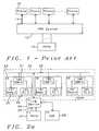
- a link to wide area network (LTW) device 26 with a network address 1 Xis connected to the wiring network 22 of the building and provides a communication port to the outside of the HVDN.
- LTW 26Connected to the LTW 26 is a PSTN 27 and an Internet service provider (ISP) 28 .
- the LTW device 26can be connected to a number of individual phone lines 29 depending on the capacity required by the home or building being services by the HVDN.
- the LTW device 26receives phone calls from and places calls to external phones by way of the PSTN 27 and Internet telephony through the ISP 28 , and connects the calls to the appropriate phone address as directed by an extension number.
- a connection of a VDM 21 to the telephone wiring 22 in a house or buildingwill most likely be made at wall connector originally used to provide a connection for a phone device; however, multiple VDM devices 21 can be connected to the telephone wiring of the house or building at these wall connectors and each can have a different length in the network.
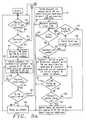
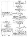
- FIG. 2 bis shown a functional flow diagram for a VDM device 21 monitoring the network for calls and participating in making connecting calls between phones and between computers.
- the term call for the flow diagram of FIG. 2 bis meant to refer to a request for a connection either between phone or between computers even though the details are not necessarily the same.
- the VDMmonitors the network for an incoming call to either the phone or the computer attached to the VDM. From the perspective of the VDM it matters little where the incoming call originates except for the network address of sender of the call.
- the ADMcontinues to monitor the network for a call 220 . If there is an incoming call 231 and if the phone or the computer is busy to the call 232 , then the call is disconnected 233 . To disconnect the call a packet containing a busy signal is sent to the sending network device, a VDM or a LTW, and the sending network device terminates the call. If there is an incoming call 231 and the phone or computer to which the call is directed is not busy 234 , then the incoming call is connected 235 . The call continues 236 until the communications are complete 237 .
- the callUpon completion of the call 237 , the call is disconnected 233 , and the VDM returns to monitoring the network for an incoming call 220 .
- the two network devices involved in the calleither two VDM devices or a VDM device and a LTW device, must communicate with each other using Ethernet packets signaling that the call has been terminated by either or both devices which make up the connection.
- Phone calls and computer callsare disconnected when a phone hang up is detected or a computer disconnect signal is detected, and the VDM returns to monitoring network for incoming calls.
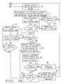
- FIG. 3 ais shown is a functional flow diagram for a VDM device 21 placing a call to a phone outside the HVDN network 20 .
- Each VDM device 21monitors the phone which is connected to it for a dial signal. If dial signal is not detected 42 , the VDM device 21 continues monitoring the phone for a dial signal. If a dial signal is detected 40 and if the signal is for a phone outside of the HVDN network 43 , then the LTW address as the destination address DA and store the dialed number 44 .
- the VDMsends a request for a connection packet to the queue 45 with DA as destination address and port ID as the source address. If the connection packet is not received 46 , send a request for a connection packet to queue 45 .
- Detect Ethernet packet from the LTW 52If the line is not busy and the connection to the remote phone is made 59 , convert a voice signal from the local phone making the call to Ethernet packets with DA as destination address 60 . If a hang up packet from the LTW is detected 61 , then hang up phone 49 . If hang up packet from LTW is not detected 62 but a phone hang up is detected by the VDM 64 , then send a hang up packet to queue with DA as the destination address 65 and hang up the phone 49 . If hang up packet from LTW is not detected 62 and if the phone is not hung up 63 , then continue to convert voice signals to Ethernet packets with DA as destination address 60 .
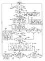
- the LTWcontinues to monitor for a connection packet 161 . If there is no hang up signal from outside line 151 , then the LTW continues to monitor connection status. If there is a hang up signal from the outside line 152 , then a packet is sent with the hang up signal to queue with DA as destination address. If line is not busy 140 and if connection is made 154 , then the LTW converts incoming voice signal to an Ethernet packet with DA as destination address and device ID as source address, and converts received voice packets with DA as source address to voice signals to be sent to outside line 155 .
- voice packetsare converted to voice signals and sent to the outside line 201 , and voice signals from outside the line are converted to packets with DA as destination address and device ID as source address 202 . If a hang up packet with source as DA is received 203 , the outside line is hung up 204 . If there is not a hang up signal from the outside line 205 , continue to hang up the outside line 204 . If a hang up signal is received from the outside line 206 , return the LTW to detecting voice packets 170 .
Landscapes
- Engineering & Computer Science (AREA)
- Computer Networks & Wireless Communication (AREA)
- Signal Processing (AREA)
- Telephonic Communication Services (AREA)
- Data Exchanges In Wide-Area Networks (AREA)
Abstract
Description
Claims (8)
Priority Applications (1)
| Application Number | Priority Date | Filing Date | Title |
|---|---|---|---|
| US09/519,608US6724750B1 (en) | 1999-12-24 | 2000-03-06 | Method for a link to a wide area network device in a home communication network |
Applications Claiming Priority (2)
| Application Number | Priority Date | Filing Date | Title |
|---|---|---|---|
| US17305299P | 1999-12-24 | 1999-12-24 | |
| US09/519,608US6724750B1 (en) | 1999-12-24 | 2000-03-06 | Method for a link to a wide area network device in a home communication network |
Publications (1)
| Publication Number | Publication Date |
|---|---|
| US6724750B1true US6724750B1 (en) | 2004-04-20 |
Family
ID=32072773
Family Applications (1)
| Application Number | Title | Priority Date | Filing Date |
|---|---|---|---|
| US09/519,608Expired - Fee RelatedUS6724750B1 (en) | 1999-12-24 | 2000-03-06 | Method for a link to a wide area network device in a home communication network |
Country Status (1)
| Country | Link |
|---|---|
| US (1) | US6724750B1 (en) |
Cited By (19)
| Publication number | Priority date | Publication date | Assignee | Title |
|---|---|---|---|---|
| US20020110114A1 (en)* | 2001-02-14 | 2002-08-15 | Taylor Karen J. | Automatic voicemail announcements with multimedia attachments |
| US20050190746A1 (en)* | 2004-02-27 | 2005-09-01 | Innomedia Pte Ltd. | Band signal detection and presentation for IP phone |
| US20060146793A1 (en)* | 2004-12-30 | 2006-07-06 | Benco David S | System and method for conference calling with VOIP terminal |
| US7130297B1 (en) | 2000-03-06 | 2006-10-31 | Sun Peter C P | Architecture for a mixed voice and data network |
| US7593394B2 (en) | 2000-04-18 | 2009-09-22 | Mosaid Technologies Incorporated | Telephone communication system over a single telephone line |
| US20090276843A1 (en)* | 2004-06-08 | 2009-11-05 | Rajesh Patel | Security event data normalization |
| US7633966B2 (en) | 2000-04-19 | 2009-12-15 | Mosaid Technologies Incorporated | Network combining wired and non-wired segments |
| US7680255B2 (en) | 2001-07-05 | 2010-03-16 | Mosaid Technologies Incorporated | Telephone outlet with packet telephony adaptor, and a network using same |
| US7686653B2 (en) | 2003-09-07 | 2010-03-30 | Mosaid Technologies Incorporated | Modular outlet |
| US7702095B2 (en) | 2003-01-30 | 2010-04-20 | Mosaid Technologies Incorporated | Method and system for providing DC power on local telephone lines |
| US7715534B2 (en) | 2000-03-20 | 2010-05-11 | Mosaid Technologies Incorporated | Telephone outlet for implementing a local area network over telephone lines and a local area network using such outlets |
| US7746905B2 (en) | 2003-03-13 | 2010-06-29 | Mosaid Technologies Incorporated | Private telephone network connected to more than one public network |
| US7965735B2 (en) | 1998-07-28 | 2011-06-21 | Mosaid Technologies Incorporated | Local area network of serial intelligent cells |
| US20120002666A1 (en)* | 2006-06-28 | 2012-01-05 | Miller Iii William V | Method for Extending Ethernet over Twisted Pair Conductors and to the Telephone Network and Plug-In Apparatus for Same Employing Standard Mechanics |
| US8351582B2 (en) | 1999-07-20 | 2013-01-08 | Mosaid Technologies Incorporated | Network for telephony and data communication |
| US8582598B2 (en) | 1999-07-07 | 2013-11-12 | Mosaid Technologies Incorporated | Local area network for distributing data communication, sensing and control signals |
| US8611528B2 (en) | 2004-02-16 | 2013-12-17 | Mosaid Technologies Incorporated | Outlet add-on module |
| US10756926B2 (en)* | 2018-07-01 | 2020-08-25 | Benchmark Electronics, Inc. | System and method for transmission of video and controller area network (CAN) data over a power slip ring assembly |
| US11032353B2 (en) | 2004-01-13 | 2021-06-08 | May Patents Ltd. | Information device |
Citations (10)
| Publication number | Priority date | Publication date | Assignee | Title |
|---|---|---|---|---|
| US5604737A (en)* | 1993-12-15 | 1997-02-18 | Hitachi, Ltd. | Voice communication system and voice communication method |
| US5742596A (en)* | 1995-11-12 | 1998-04-21 | Phonet Communication Ltd. | Network based distributed PBX system |
| US5790548A (en) | 1996-04-18 | 1998-08-04 | Bell Atlantic Network Services, Inc. | Universal access multimedia data network |
| US5892764A (en)* | 1996-09-16 | 1999-04-06 | Sphere Communications Inc. | ATM LAN telephone system |
| US5929748A (en) | 1997-06-12 | 1999-07-27 | Microsoft Corporation | Automated home control using existing electrical lines as a communications medium |
| US5991634A (en) | 1997-02-28 | 1999-11-23 | Lucent Technologies Inc. | "Plug and play" telephone system |
| US5999612A (en) | 1997-05-27 | 1999-12-07 | International Business Machines Corporation | Integrated telephony and data services over cable networks |
| US6005861A (en) | 1995-11-22 | 1999-12-21 | Samsung Electronics Co., Ltd. | Home multimedia network architecture |
| US6456625B1 (en)* | 1997-10-16 | 2002-09-24 | Fujitsu Limited | LAN telephone switching system |
| US6574242B1 (en)* | 1998-06-10 | 2003-06-03 | Merlot Communications, Inc. | Method for the transmission and control of audio, video, and computer data over a single network fabric |
- 2000
- 2000-03-06USUS09/519,608patent/US6724750B1/ennot_activeExpired - Fee Related
Patent Citations (10)
| Publication number | Priority date | Publication date | Assignee | Title |
|---|---|---|---|---|
| US5604737A (en)* | 1993-12-15 | 1997-02-18 | Hitachi, Ltd. | Voice communication system and voice communication method |
| US5742596A (en)* | 1995-11-12 | 1998-04-21 | Phonet Communication Ltd. | Network based distributed PBX system |
| US6005861A (en) | 1995-11-22 | 1999-12-21 | Samsung Electronics Co., Ltd. | Home multimedia network architecture |
| US5790548A (en) | 1996-04-18 | 1998-08-04 | Bell Atlantic Network Services, Inc. | Universal access multimedia data network |
| US5892764A (en)* | 1996-09-16 | 1999-04-06 | Sphere Communications Inc. | ATM LAN telephone system |
| US5991634A (en) | 1997-02-28 | 1999-11-23 | Lucent Technologies Inc. | "Plug and play" telephone system |
| US5999612A (en) | 1997-05-27 | 1999-12-07 | International Business Machines Corporation | Integrated telephony and data services over cable networks |
| US5929748A (en) | 1997-06-12 | 1999-07-27 | Microsoft Corporation | Automated home control using existing electrical lines as a communications medium |
| US6456625B1 (en)* | 1997-10-16 | 2002-09-24 | Fujitsu Limited | LAN telephone switching system |
| US6574242B1 (en)* | 1998-06-10 | 2003-06-03 | Merlot Communications, Inc. | Method for the transmission and control of audio, video, and computer data over a single network fabric |
Non-Patent Citations (3)
| Title |
|---|
| Chen et al., "Emerging Home Digital Networking Needs", Proceedings-1997 Fourth Int'l Workshop on Community Networking, IEEE, pp. 7-12. |
| Chen et al., "Emerging Home Digital Networking Needs", Proceedings—1997 Fourth Int'l Workshop on Community Networking, IEEE, pp. 7-12. |
| Hwang et al., "Standardization Activities and Technology Competitors for the In-Home Networking", Proceedings of 1998 International Conference on Communication Technology, pp. 787-832. |
Cited By (48)
| Publication number | Priority date | Publication date | Assignee | Title |
|---|---|---|---|---|
| US7965735B2 (en) | 1998-07-28 | 2011-06-21 | Mosaid Technologies Incorporated | Local area network of serial intelligent cells |
| US8908673B2 (en) | 1998-07-28 | 2014-12-09 | Conversant Intellectual Property Management Incorporated | Local area network of serial intelligent cells |
| US8885659B2 (en) | 1998-07-28 | 2014-11-11 | Conversant Intellectual Property Management Incorporated | Local area network of serial intelligent cells |
| US8885660B2 (en) | 1998-07-28 | 2014-11-11 | Conversant Intellectual Property Management Incorporated | Local area network of serial intelligent cells |
| US8867523B2 (en) | 1998-07-28 | 2014-10-21 | Conversant Intellectual Property Management Incorporated | Local area network of serial intelligent cells |
| US8325636B2 (en) | 1998-07-28 | 2012-12-04 | Mosaid Technologies Incorporated | Local area network of serial intelligent cells |
| US7986708B2 (en) | 1998-07-28 | 2011-07-26 | Mosaid Technologies Incorporated | Local area network of serial intelligent cells |
| US8582598B2 (en) | 1999-07-07 | 2013-11-12 | Mosaid Technologies Incorporated | Local area network for distributing data communication, sensing and control signals |
| US8351582B2 (en) | 1999-07-20 | 2013-01-08 | Mosaid Technologies Incorporated | Network for telephony and data communication |
| US8929523B2 (en) | 1999-07-20 | 2015-01-06 | Conversant Intellectual Property Management Inc. | Network for telephony and data communication |
| US7130297B1 (en) | 2000-03-06 | 2006-10-31 | Sun Peter C P | Architecture for a mixed voice and data network |
| US8363797B2 (en) | 2000-03-20 | 2013-01-29 | Mosaid Technologies Incorporated | Telephone outlet for implementing a local area network over telephone lines and a local area network using such outlets |
| US8855277B2 (en) | 2000-03-20 | 2014-10-07 | Conversant Intellectual Property Managment Incorporated | Telephone outlet for implementing a local area network over telephone lines and a local area network using such outlets |
| US7715534B2 (en) | 2000-03-20 | 2010-05-11 | Mosaid Technologies Incorporated | Telephone outlet for implementing a local area network over telephone lines and a local area network using such outlets |
| US8000349B2 (en) | 2000-04-18 | 2011-08-16 | Mosaid Technologies Incorporated | Telephone communication system over a single telephone line |
| US8559422B2 (en) | 2000-04-18 | 2013-10-15 | Mosaid Technologies Incorporated | Telephone communication system over a single telephone line |
| US7593394B2 (en) | 2000-04-18 | 2009-09-22 | Mosaid Technologies Incorporated | Telephone communication system over a single telephone line |
| US8223800B2 (en) | 2000-04-18 | 2012-07-17 | Mosaid Technologies Incorporated | Telephone communication system over a single telephone line |
| US8873575B2 (en) | 2000-04-19 | 2014-10-28 | Conversant Intellectual Property Management Incorporated | Network combining wired and non-wired segments |
| US8982903B2 (en) | 2000-04-19 | 2015-03-17 | Conversant Intellectual Property Management Inc. | Network combining wired and non-wired segments |
| US8848725B2 (en) | 2000-04-19 | 2014-09-30 | Conversant Intellectual Property Management Incorporated | Network combining wired and non-wired segments |
| US8982904B2 (en) | 2000-04-19 | 2015-03-17 | Conversant Intellectual Property Management Inc. | Network combining wired and non-wired segments |
| US8873586B2 (en) | 2000-04-19 | 2014-10-28 | Conversant Intellectual Property Management Incorporated | Network combining wired and non-wired segments |
| US7633966B2 (en) | 2000-04-19 | 2009-12-15 | Mosaid Technologies Incorporated | Network combining wired and non-wired segments |
| US8867506B2 (en) | 2000-04-19 | 2014-10-21 | Conversant Intellectual Property Management Incorporated | Network combining wired and non-wired segments |
| US20020110114A1 (en)* | 2001-02-14 | 2002-08-15 | Taylor Karen J. | Automatic voicemail announcements with multimedia attachments |
| US7002951B2 (en)* | 2001-02-14 | 2006-02-21 | 3Com Corporation | Automatic voicemail announcements with multimedia attachments |
| US8472593B2 (en) | 2001-07-05 | 2013-06-25 | Mosaid Technologies Incorporated | Telephone outlet with packet telephony adaptor, and a network using same |
| US7769030B2 (en) | 2001-07-05 | 2010-08-03 | Mosaid Technologies Incorporated | Telephone outlet with packet telephony adapter, and a network using same |
| US7680255B2 (en) | 2001-07-05 | 2010-03-16 | Mosaid Technologies Incorporated | Telephone outlet with packet telephony adaptor, and a network using same |
| US8761186B2 (en) | 2001-07-05 | 2014-06-24 | Conversant Intellectual Property Management Incorporated | Telephone outlet with packet telephony adapter, and a network using same |
| US8787562B2 (en) | 2003-01-30 | 2014-07-22 | Conversant Intellectual Property Management Inc. | Method and system for providing DC power on local telephone lines |
| US7702095B2 (en) | 2003-01-30 | 2010-04-20 | Mosaid Technologies Incorporated | Method and system for providing DC power on local telephone lines |
| US8107618B2 (en) | 2003-01-30 | 2012-01-31 | Mosaid Technologies Incorporated | Method and system for providing DC power on local telephone lines |
| US7746905B2 (en) | 2003-03-13 | 2010-06-29 | Mosaid Technologies Incorporated | Private telephone network connected to more than one public network |
| US8238328B2 (en) | 2003-03-13 | 2012-08-07 | Mosaid Technologies Incorporated | Telephone system having multiple distinct sources and accessories therefor |
| US7686653B2 (en) | 2003-09-07 | 2010-03-30 | Mosaid Technologies Incorporated | Modular outlet |
| US11032353B2 (en) | 2004-01-13 | 2021-06-08 | May Patents Ltd. | Information device |
| US8611528B2 (en) | 2004-02-16 | 2013-12-17 | Mosaid Technologies Incorporated | Outlet add-on module |
| US20050190746A1 (en)* | 2004-02-27 | 2005-09-01 | Innomedia Pte Ltd. | Band signal detection and presentation for IP phone |
| US7471671B2 (en)* | 2004-02-27 | 2008-12-30 | Innomedia Pte Ltd. | Band signal detection and presentation for IP phone |
| US20090276843A1 (en)* | 2004-06-08 | 2009-11-05 | Rajesh Patel | Security event data normalization |
| US9060024B2 (en)* | 2004-06-08 | 2015-06-16 | Log Storm Security, Inc. | Security event data normalization |
| US20060146793A1 (en)* | 2004-12-30 | 2006-07-06 | Benco David S | System and method for conference calling with VOIP terminal |
| US7693133B2 (en)* | 2004-12-30 | 2010-04-06 | Alcatel-Lucent Usa Inc. | System and method for conference calling with VOIP terminal |
| US20120002666A1 (en)* | 2006-06-28 | 2012-01-05 | Miller Iii William V | Method for Extending Ethernet over Twisted Pair Conductors and to the Telephone Network and Plug-In Apparatus for Same Employing Standard Mechanics |
| US8837712B2 (en)* | 2006-06-28 | 2014-09-16 | Hubbell Incorporated | Method for extending Ethernet over twisted pair conductors and to the telephone network and plug-in apparatus for same employing standard mechanics |
| US10756926B2 (en)* | 2018-07-01 | 2020-08-25 | Benchmark Electronics, Inc. | System and method for transmission of video and controller area network (CAN) data over a power slip ring assembly |
Similar Documents
| Publication | Publication Date | Title |
|---|---|---|
| US6724750B1 (en) | Method for a link to a wide area network device in a home communication network | |
| US8717950B2 (en) | Multi-mode endpoint in a communication network system and methods thereof | |
| EP0898837B1 (en) | An access network over a dedicated medium | |
| US6141345A (en) | Signal processing resource allocation for internet-based telephony | |
| US6167043A (en) | Method and system for small office and home office telephone private branch exchange allowing simultaneous data and voice communications | |
| US20070211698A1 (en) | System and device for integrating ip and analog telephone systems | |
| JPH1146260A (en) | System adapting to broadband network, computer telephone adaptor and path designation system | |
| JP2004524755A (en) | VoIP system | |
| JP2011501616A (en) | System for supporting analog telephone in IP telephony network | |
| CA2588051A1 (en) | Apparatus and method of remotely enabling a special mode of operation of an endpoint in a voip network | |
| KR20000055380A (en) | Voice communication apparatus | |
| US7489680B2 (en) | Method for connecting routing device in existing wiring | |
| US6870852B1 (en) | Combination router bridge in an integrated services hub | |
| JPH10224408A5 (en) | ||
| US6856614B1 (en) | Method for a mixed voice and data device in a home communications network | |
| US7130297B1 (en) | Architecture for a mixed voice and data network | |
| JP4465525B2 (en) | IP telephone exchange method and apparatus | |
| US7668180B2 (en) | Distributed multimedia and messaging router over layer 2 | |
| US7042996B1 (en) | Method and apparatus for cas-based ring limiting of FXS ports | |
| JP2001358830A (en) | Network telephone communication path establishment method and communication path control device | |
| US20050114546A1 (en) | Method for establishing virtual intranet over internet based on a digital closed network constructed from a telephone exchange and a key telephone system and the virtual intranet structure using the same | |
| JP4215550B2 (en) | Private branch exchange system for intersystem connection by IP and system information transmission method thereof | |
| WO1999038312A1 (en) | Computer telephony integrated pbx | |
| US20050122984A1 (en) | Roaming communication system over internet | |
| JP2003143320A (en) | Method for reaching incoming call to ip terminal |
Legal Events
| Date | Code | Title | Description |
|---|---|---|---|
| AS | Assignment | Owner name:WARPCOM TECHNOLOGIES, INC., CALIFORNIA Free format text:ASSIGNMENT OF ASSIGNORS INTEREST;ASSIGNOR:SUN, PETER;REEL/FRAME:010664/0443 Effective date:20000228 | |
| AS | Assignment | Owner name:LARA NETWORKS, INC., CALIFORNIA Free format text:MERGER;ASSIGNOR:WARPCOM TECHNOLOGIES, INC.;REEL/FRAME:017198/0849 Effective date:20000719 | |
| FEPP | Fee payment procedure | Free format text:PAYOR NUMBER ASSIGNED (ORIGINAL EVENT CODE: ASPN); ENTITY STATUS OF PATENT OWNER: LARGE ENTITY Free format text:PAYER NUMBER DE-ASSIGNED (ORIGINAL EVENT CODE: RMPN); ENTITY STATUS OF PATENT OWNER: LARGE ENTITY Free format text:PAT HOLDER NO LONGER CLAIMS SMALL ENTITY STATUS, ENTITY STATUS SET TO UNDISCOUNTED (ORIGINAL EVENT CODE: STOL); ENTITY STATUS OF PATENT OWNER: LARGE ENTITY | |
| REFU | Refund | Free format text:REFUND - SURCHARGE, PETITION TO ACCEPT PYMT AFTER EXP, UNINTENTIONAL (ORIGINAL EVENT CODE: R2551); ENTITY STATUS OF PATENT OWNER: LARGE ENTITY | |
| FPAY | Fee payment | Year of fee payment:4 | |
| REMI | Maintenance fee reminder mailed | ||
| AS | Assignment | Owner name:SILICON VALLEY BANK, CALIFORNIA Free format text:SECURITY AGREEMENT;ASSIGNORS:NETLOGIC MICROSYSTEMS, INC.;NETLOGIC MICROSYSTEMS INTERNATIONAL LIMITED;NETLOGIC MICROSYSTEMS CAYMANS LIMITED;REEL/FRAME:022973/0710 Effective date:20090717 Owner name:SILICON VALLEY BANK,CALIFORNIA Free format text:SECURITY AGREEMENT;ASSIGNORS:NETLOGIC MICROSYSTEMS, INC.;NETLOGIC MICROSYSTEMS INTERNATIONAL LIMITED;NETLOGIC MICROSYSTEMS CAYMANS LIMITED;REEL/FRAME:022973/0710 Effective date:20090717 | |
| FEPP | Fee payment procedure | Free format text:PAYOR NUMBER ASSIGNED (ORIGINAL EVENT CODE: ASPN); ENTITY STATUS OF PATENT OWNER: LARGE ENTITY Free format text:PAYER NUMBER DE-ASSIGNED (ORIGINAL EVENT CODE: RMPN); ENTITY STATUS OF PATENT OWNER: LARGE ENTITY | |
| AS | Assignment | Owner name:NETLOGIC MICROSYSTEMS INTERNATIONAL LIMITED, CALIF Free format text:RELEASE;ASSIGNOR:SILICON VALLEY BANK;REEL/FRAME:025051/0248 Effective date:20100809 Owner name:NETLOGIC MICROSYSTEMS CAYMANS LIMITED, CALIFORNIA Free format text:RELEASE;ASSIGNOR:SILICON VALLEY BANK;REEL/FRAME:025051/0248 Effective date:20100809 Owner name:NETLOGIC MICROSYSTEMS, INC., CALIFORNIA Free format text:RELEASE;ASSIGNOR:SILICON VALLEY BANK;REEL/FRAME:025051/0248 Effective date:20100809 | |
| FPAY | Fee payment | Year of fee payment:8 | |
| AS | Assignment | Owner name:BROADCOM CORPORATION, CALIFORNIA Free format text:ASSIGNMENT OF ASSIGNORS INTEREST;ASSIGNOR:NETLOGIC I LLC;REEL/FRAME:035443/0763 Effective date:20150327 Owner name:NETLOGIC I LLC, DELAWARE Free format text:CHANGE OF NAME;ASSIGNOR:NETLOGIC MICROSYSTEMS, INC.;REEL/FRAME:035443/0824 Effective date:20130123 | |
| REMI | Maintenance fee reminder mailed | ||
| AS | Assignment | Owner name:BANK OF AMERICA, N.A., AS COLLATERAL AGENT, NORTH CAROLINA Free format text:PATENT SECURITY AGREEMENT;ASSIGNOR:BROADCOM CORPORATION;REEL/FRAME:037806/0001 Effective date:20160201 Owner name:BANK OF AMERICA, N.A., AS COLLATERAL AGENT, NORTH Free format text:PATENT SECURITY AGREEMENT;ASSIGNOR:BROADCOM CORPORATION;REEL/FRAME:037806/0001 Effective date:20160201 | |
| LAPS | Lapse for failure to pay maintenance fees | ||
| STCH | Information on status: patent discontinuation | Free format text:PATENT EXPIRED DUE TO NONPAYMENT OF MAINTENANCE FEES UNDER 37 CFR 1.362 | |
| FP | Lapsed due to failure to pay maintenance fee | Effective date:20160420 | |
| AS | Assignment | Owner name:AVAGO TECHNOLOGIES GENERAL IP (SINGAPORE) PTE. LTD., SINGAPORE Free format text:ASSIGNMENT OF ASSIGNORS INTEREST;ASSIGNOR:BROADCOM CORPORATION;REEL/FRAME:041706/0001 Effective date:20170120 Owner name:AVAGO TECHNOLOGIES GENERAL IP (SINGAPORE) PTE. LTD Free format text:ASSIGNMENT OF ASSIGNORS INTEREST;ASSIGNOR:BROADCOM CORPORATION;REEL/FRAME:041706/0001 Effective date:20170120 | |
| AS | Assignment | Owner name:BROADCOM CORPORATION, CALIFORNIA Free format text:TERMINATION AND RELEASE OF SECURITY INTEREST IN PATENTS;ASSIGNOR:BANK OF AMERICA, N.A., AS COLLATERAL AGENT;REEL/FRAME:041712/0001 Effective date:20170119 | |
| AS | Assignment | Owner name:AVAGO TECHNOLOGIES INTERNATIONAL SALES PTE. LIMITE Free format text:MERGER;ASSIGNOR:AVAGO TECHNOLOGIES GENERAL IP (SINGAPORE) PTE. LTD.;REEL/FRAME:047195/0026 Effective date:20180509 | |
| AS | Assignment | Owner name:AVAGO TECHNOLOGIES INTERNATIONAL SALES PTE. LIMITE Free format text:CORRECTIVE ASSIGNMENT TO CORRECT THE EFFECTIVE DATE OF MERGER PREVIOUSLY RECORDED ON REEL 047195 FRAME 0026. ASSIGNOR(S) HEREBY CONFIRMS THE MERGER;ASSIGNOR:AVAGO TECHNOLOGIES GENERAL IP (SINGAPORE) PTE. LTD.;REEL/FRAME:047477/0423 Effective date:20180905 |