US6724566B2 - Acoustic damper for a disc drive - Google Patents
Acoustic damper for a disc driveDownload PDFInfo
- Publication number
- US6724566B2 US6724566B2US10/104,572US10457202AUS6724566B2US 6724566 B2US6724566 B2US 6724566B2US 10457202 AUS10457202 AUS 10457202AUS 6724566 B2US6724566 B2US 6724566B2
- Authority
- US
- United States
- Prior art keywords
- top cover
- base plate
- disc drive
- acoustic damper
- pole
- Prior art date
- Legal status (The legal status is an assumption and is not a legal conclusion. Google has not performed a legal analysis and makes no representation as to the accuracy of the status listed.)
- Expired - Lifetime, expires
Links
Images


Classifications
- G—PHYSICS
- G11—INFORMATION STORAGE
- G11B—INFORMATION STORAGE BASED ON RELATIVE MOVEMENT BETWEEN RECORD CARRIER AND TRANSDUCER
- G11B33/00—Constructional parts, details or accessories not provided for in the other groups of this subclass
- G11B33/02—Cabinets; Cases; Stands; Disposition of apparatus therein or thereon
- G11B33/08—Insulation or absorption of undesired vibrations or sounds
- G—PHYSICS
- G11—INFORMATION STORAGE
- G11B—INFORMATION STORAGE BASED ON RELATIVE MOVEMENT BETWEEN RECORD CARRIER AND TRANSDUCER
- G11B33/00—Constructional parts, details or accessories not provided for in the other groups of this subclass
- G11B33/14—Reducing influence of physical parameters, e.g. temperature change, moisture, dust
- G11B33/1446—Reducing contamination, e.g. by dust, debris
- G11B33/1466—Reducing contamination, e.g. by dust, debris sealing gaskets
Definitions
- the inventionis generally directed to the field of disc drives and more particularly to controlling acoustic noise emissions emanating from a disc drive voice coil motor assembly while maintaining a sealed environment for the internal components of a disc drive.
- Modern disc drivescomprise one or more discs that are coated with a magnetizable medium and mounted on the hub of a spindle motor for rotation at a constant high speed. Information is stored on the discs in a plurality of concentric circular tracks. Data is typically written to, and read from, the tracks via transducers (“heads”) typically mounted to a radial actuator assembly, which positions the heads relative to the discs.
- transducersheads
- Various disc drive components, including the spindle motor and the actuator assemblyare fastened to a base plate.
- a top coveris attached to the base plate and sealed with a pressure seal to enclose and create a sealed environment for the disc drive components. This sealed environment reduces the chance that outside contaminants, such as dust, will interfere with read/write operations of the actuator assembly, among other things.
- Radial actuator assembliesemploy a voice coil motor (VCM) to position the heads with respect to the disc surfaces.
- VCMvoice coil motor
- the headsare mounted via flexures at the ends of a plurality of actuator arms, which project radially outward from a substantially cylindrical actuator body.
- the actuator bodypivots about a shaft mounted to the disc drive housing at a position closely adjacent the outer extreme of the discs.
- the pivot shaftis parallel with the axis of rotation of the spindle motor and the discs, so that the heads move in a plane parallel with the surfaces of the discs.
- the VCMincludes a coil mounted on the side of the actuator body opposite the actuator arms between an array of permanent magnets which are positioned above and/or below the coil on top and/or bottom magnet plates or poles, respectively.
- an electromagnetic fieldis generated.
- the generated electromagnetic fieldinteracts with the magnetic field of the permanent magnets thus causing the coil to move relative to the magnets in accordance with the well-known Lorentz relationship.
- the actuator bodypivots about the pivot shaft and the heads are moved across the disc surfaces.
- the headsare supported on the actuator arms in a position over the discs by actuator slider assemblies, which include air-bearing surfaces designed to interact with a thin layer of moving air generated by the rotation of the discs, so that the heads “fly” over the disc surfaces.
- the headswrite data to a selected data track on the disc surface by selectively magnetizing portions of the data track through the application of a time-varying write current to the head.
- the headdetects flux transitions in the magnetic fields on the data track and converts these flux transitions to a signal which is decoded by read channel circuitry of the disc drive.
- a closed-loop servo systemis typically used to control the position of the heads with respect to the disc surfaces. More particularly, during a track following mode in which a head is caused to follow a selected data track, servo information is read which provides a position error signal indicative of the position of the head relative to a center line of the track. The position error signal is used, when necessary, to generate a correction signal that in turn is provided to a power amplifier. The power amplifier then passes current through the actuator coil to adjust the position of the head relative to the track.
- the servo systemreceives the address of the destination track and generates control signals that cause the heads to initially accelerate and then subsequently decelerate as the head nears the destination track. At some point towards the end of the deceleration of the head, the servo system will transition to a settle mode during which the head is settled onto the destination track and, thereafter, the servo system causes the head to follow the destination track in a track following mode.
- a general trend in the disc drive industryis to reduce the level of acoustic emissions or noise generated by disc drives, preferably reducing the noise to a level that is below the human hearing threshold.
- Idle noiseresults from the operation of the spindle motor and its associated rotating discs.
- Significant improvements in reducing idle noisehave been achieved by replacing ball bearing assemblies with hydraulic bearings in the spindle motor.
- seek noiseresults from vibrations in the permanent magnets and/or poles of the VCM caused when current is passed through the VCM coil.
- the vibrations occurring in the poles of the voice coil motormay be transmitted to the top cover and/or the disc drive base plate either as sympathetic vibrations or as direct transmissions.
- a slowed down seek operational settingis often provided in disc drives as an optional setting.
- the alternative operational setting in disc drives having a quite seek settingis an operational setting commonly referred to as the performance seek, where the seek to the track occurs quickly relative to the quite seek.
- the quite seekreduces the acoustical emissions from the disc drive, it also necessarily reduces disc drive performance.
- Disc drives including such quite seek operational settingsare often employed in areas, such as government and private offices, that are subject to strict environmental noise limitations.
- Another approach to reducing the acoustical emissions from the disc driveis to add a damping material between the upper magnetic plate or top pole and the top cover of the disc drive.
- the top covermust be sufficiently rigid to provide deflection of the damping material.
- the stiffness required for this approach to be usefulmay add unacceptable weight and manufacturing costs to the disc drive.
- the coveris not sufficiently stiff, the addition of damping material between the cover and the top pole may cause the top cover to deform and breach the pressure seal between the cover and the base plate. Breach of this pressure seal allows contaminants into the disc drive and thus, may prevent the disc drive from operating effectively.
- adding a damper between the top pole and the top covermay add significant costs to the manufacturing of the disc drive.
- the various embodiments of the present inventionrelate to systems and methods of minimizing vibrationally induced noise in a disc drive servo system. Additionally, embodiments of the present invention relate to reducing vibrationally induced acoustical emissions from a disc drive device.
- a disc drivehas a base plate, a voice coil motor operably attached to the base plate, and a top cover attached to the base plate with two perimeter fasteners and one interior fastener through corresponding apertures in the top cover.
- the two perimeter fasteners/apertures and the interior fastener/apertureform a triangular portion of the top cover that has increased stiffness and rigidity due to the proximity of the fasteners to each other.
- a pressure sealis positioned between the top cover and the base plate to seal the disc drive to form an internal sealed environment for the various disc drive components.
- An acoustic damperis positioned between and contacts the voice coil motor and the triangular portion of the top cover to dampen vibrations occurring in the voice coil motor and the top cover.
- the acoustic damperis made of the same material as the pressure seal.
- a second acoustic damperis positioned between the base plate and the voice coil motor such that it does not contact the top cover.
- the second acoustic damperneed not to be positioned within the triangle formed by the two perimeter fasteners and the interior fastener.
- the voice coil motorincludes a bottom pole attached to the base plate, a top pole operably connected to the bottom pole in a manner such that the top pole is maintained in a spaced relationship to the bottom pole, and a single magnet pair positioned between the top pole and the bottom pole.
- the first acoustic damperis preferably positioned between the top pole and the top cover and the second acoustic damper is preferably positioned between the bottom pole and the bottom cover.
- a stiffening ridgeis added to the top cover to create an isolated portion of the top cover over the top pole of the voice coil motor; the isolated portion is stiffer and more rigid than the remainder of the top cover.
- the isolated portionmay be outside of the triangular portion, may partially overlap the triangular portion, or may be contained entirely within the triangular portion.
- the acoustic dampermay be positioned between the isolated portion and the voice coil motor to dampen acoustic noise without adversely affecting the integrity of the pressure seal.
- the disc driveis manufactured by operably attaching the voice coil motor to the base plate and then attaching the top cover to the base plate using at least the two perimeter fasteners and the interior fastener.
- a pressure sealis positioned between and contacts the top cover and the base plate and an acoustic damper is positioned between and contacts the voice coil motor and the triangular portion of the top cover.
- the pressure seal and acoustic dampermay be applied to the top cover prior to attaching the cover to the base plate or applied to the base plate and the voice coil motor, respectively prior to attaching the cover to the base plate.
- the same processis preferably used to apply the acoustic damper as to position the pressure seal which adds little or no additional cost to the manufacture of the disc drive.
- FIG. 1is a top view of a disc drive showing the primary internal disc drive components, with the cover shown partially cutaway.
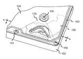
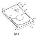
- FIG. 2is top plan view of the disc drive of FIG. 1 with a top cover incorporating an acoustic damper (shown in shadow) in accordance with an embodiment of the present invention.
- FIG. 3is a top view of the disc drive of FIG. 2 with the cover shown partially cutaway to expose the acoustic damper.
- FIG. 4is cross-sectional view through lines 4 — 4 of FIG. 3 .
- FIG. 5is cross-sectional view of an alternative embodiment of the present invention incorporating an acoustic damper contacting the top cover and top pole and an acoustic damper contacting the base plate and the bottom pole.
- FIG. 6is a top view of a disc drive incorporating another embodiment of the present invention before the top cover is attached.
- FIG. 7is a bottom plan view of a top cover incorporating another embodiment of the present invention, with the position of the top pole shown in shadow.
- FIG. 8is a bottom plan view of a top cover incorporating another embodiment of the present invention, with the position of the top pole shown in shadow.
- FIG. 9is top plan view of the disc drive with a top cover incorporating yet another embodiment of the present invention.
- FIG. 10is a bottom plan view of a top cover incorporating another embodiment of the present invention, with the position of the top pole shown in shadow.
- the present disclosuredescribes methods and systems for dampening vibrations in, and acoustical emissions from, a disc drive device. More particularly, the present disclosure describes a system and method for reducing vibrational modes induced in and by a disc drive voice coil motor (VCM), referred to herein as “seek noise.”
- VCMdisc drive voice coil motor
- the disc drive 100includes a base plate 102 to which various components of the disc drive 100 are mounted.
- a top cover 104shown partially cut away in FIG. 1, is mounted to the base plate 102 with a series of six perimeter fasteners 150 - 155 , such as screws, through six perimeter apertures 160 - 165 in the cover 104 and one interior screw 156 through one interior aperture 166 in the top cover 104 .
- a pressure seal 103applied to a perimeter of the top cover 104 , seals the top cover 104 to the base plate 102 to form an internal, sealed environment for the disc drive components when the top cover 104 is attached to the base plate 102 .
- the pressure seal 103may be first applied to a perimeter of the base plate 102 as opposed to the top cover 104 .
- the disc drive components contained within the sealed disc driveinclude a spindle motor 106 , one or more discs 108 , and an actuator assembly 110 .
- the spindle motor 106rotates the discs 108 at a constant high speed. Information is written to and read from tracks on the discs 108 through the use of the actuator assembly 110 , which rotates during a seek operation about a bearing shaft assembly 112 positioned adjacent the discs 108 .
- the actuator assembly 110includes a plurality of actuator arms 114 which extend toward and over the discs 108 , with one or more flexures 116 extending from each of the actuator arms 114 .
- a head 118mounted at the distal end of each of the flexures 116 is a head 118 which includes an air bearing slider (not shown) that enables the head 118 to fly in close proximity to a corresponding surface of an associated disc 108 .
- the track position of the heads 118is controlled through the use of a voice coil motor (VCM) 124 , which typically includes a coil 126 attached to the actuator assembly 110 , a top pole 130 , a bottom pole 132 (FIG. 4 ), as well as one or more permanent magnet pairs 128 , positioned between the top pole 130 and the bottom pole 132 , which establish a magnetic field in which the coil 126 is immersed.
- VCMvoice coil motor
- the bottom pole 132(shown in FIG. 5) is attached to the base plate 102 and the top pole 130 is operably connected to the bottom pole 132 and/or base plate 102 in spaced relation to the bottom pole 132 with a first screw 134 .
- An additional second screw 136may be used to fasten an opposite side of the top pole 130 to the bottom pole 132 and/or base plate 102 .
- the controlled application of current to the coil 126causes magnetic interaction between the magnet pair(s) 128 and the coil 126 so that the coil 126 moves in accordance with the well known Lorentz relationship.
- the actuator assembly 110pivots about the bearing shaft assembly 112 , and the heads 118 are caused to move across the surfaces of the discs 108 .
- a flex assembly 140provides the requisite electrical connection paths for the actuator assembly 110 while allowing pivotal movement of the actuator assembly 110 during operation.
- the flex assemblytypically includes circuitry to which head wires (not shown) are connected. The head wires are routed along the actuator arms 114 and the flexures 116 to the heads 118 .
- the flex assembly circuitrytypically controls the write currents applied to the heads 118 during a write operation and amplifies read signals generated by the heads 118 during a read operation.
- the flex assembly 140terminates at a flex bracket 144 for communication through the base plate 102 to a disc drive printed circuit board (not shown) mounted to the bottom side of the disc drive 100 .
- FIG. 2shows a plan view of a disc drive with the top cover 104 attached.
- the screws 150 , 151 , and 156 and/or apertures 160 , 161 , and 166(shown in FIG. 6) define three points of a triangular portion 170 of the top cover 104 .
- the triangular portion 170 of the top cover 104becomes more stiff and rigid and more resistant to deformation than the remaining portion of the cover 104 . This additional stiffness is due in part to the strength added by the close proximity of the screws 150 , 151 , and 156 to each other. While the interior screw 156 is shown mounted through the center of the bearing shaft assembly 112 (shown in FIG.
- An acoustic damper 200(shown by dashed lines in FIG. 2) is positioned between the top cover 104 and the top pole 130 such that the acoustic damper contacts the top cover 104 within the triangular portion 170 .
- FIG. 3illustrates a top view of the disc drive shown in FIG. 1 with the cover 104 partially cutaway to expose the acoustic damper 200 .
- FIG. 4shows a cross sectional view along line 4 — 4 of FIG. 3 .
- the triangular portion 170 of the top cover 104exerts pressure on the acoustic damper 200 thereby allowing the acoustic damper 200 to dampen acoustic vibrations in the top pole 130 caused by seek noise, thereby preventing vibrations from passing through the top cover 104 .
- the addition of the acoustic damper 200 within the triangular portion 170will not cause the top cover 104 to deform and breach in the pressure seal 103 because the triangular portion 170 has extra stiffness or rigidity due in part to the location of the screws 150 , 151 , and 156 .
- the pressure exerted by the acoustic damper 200 on the triangular portion 170will not cause the remaining portion of the top cover 104 to deform because the triangular portion 170 is stiff enough to endure this pressure. In this way, the acoustic damper 200 does not affect the integrity of the pressure seal 103 .
- the acoustic damper 200is made of a damping material, such as, vicsoelastic damping material, fluoroelastomer damping material, polyurethane elastomers, rubber, fluorocarbon elastomers, epoxy thermoset elastomers, ethylene-Propylene (EPDM), BUNA-N (Nitrile) (NBR), silicone elastomers, neoprene (synthetic rubber), or fluorosilicone elastomers.
- a damping materialsuch as, vicsoelastic damping material, fluoroelastomer damping material, polyurethane elastomers, rubber, fluorocarbon elastomers, epoxy thermoset elastomers, ethylene-Propylene (EPDM), BUNA-N (Nitrile) (NBR), silicone elastomers, neoprene (synthetic rubber), or fluorosilicone elastomers
- the acoustic damper 200is made of the same material as the pressure seal 103 and is preferably applied to an interior surface of the top cover 104 using the same process that is used to apply the pressure seal 103 to the interior surface of the top cover 104 . If the acoustic damper 200 is applied within the triangular portion 170 of the top cover 104 at the same time as the pressure seal 103 and using the same material as the pressure seal 103 , there will be little or no extra cost associated with the addition of acoustic damper 200 .
- Various methodsmay be used to apply the acoustic damper 200 to the triangular portion 170 of the cover 104 and/or the top pole 130 , including without limitation, dispensing or applying the acoustic damper 200 as an elastomer bead followed by one or more curing processes; directly molding the acoustic damper 200 on the cover; molding the acoustic damper 200 separately (either stand alone or on a backbone or substrate), which results in the seal becoming a separate part for placement between the cover and voice coil motor; or a process involving molding and/or extruding the acoustic damper 200 in a three-dimensional piece followed by slicing process to produce each individual acoustic damper 200 , which would then be attached to the cover 104 and/or the voice coil motor 124 using adhesive. These same methods may be used to position the pressure seal 103 between the top cover 104 and the base plate 102 .
- the acoustic damper 200may be applied to the top cover 104 prior to engaging it with the top pole 130 , which will happen when the cover is attached to the base plate 102 as shown in FIGS. 7 and 8. Or the acoustic damper 200 may be applied to the top pole 130 prior to engaging it with the top cover 104 when the top cover 104 is attached to the base plate 102 as shown in FIG. 6 .
- the acoustic damper 200may be made of any shape, including without limitation, a rounded V-shape (FIG. 3 ), a wavy line (FIG. 6 ), a U-shape (FIG. 7 ), and a spiral (FIG. 8) so long as the acoustic damper 200 is contained within the triangular portion 170 .
- a rounded V-shapeFIG. 3
- a wavy lineFIG. 6
- U-shapeFIG. 7
- a spiralFIG. 8
- the more spaced that the acoustic damper 200 is from the screws 134 and 136 fastening the voice coil motor to base platethe better that the acoustic damper 200 will dampen the seek noise. So for example, if the VCM 124 is fastened to the base plate 102 with a single screw 134 , the acoustic damper 200 will dampen more seek noise if it is positioned in the farthest point from screw 134 within the triangular portion 170 .
- the acoustic damper 200will dampen more seek noise if it is positioned equidistant from the two screws 134 and 136 while still being positioned within the triangle portion 170 .
- the more pressure exerted between the acoustic damper 200 and the triangular portion 170the better that the acoustic damper 200 will dampen the seek noise.
- Pressurepreferably ranges in the amount of a few psi to several hundred psi. If the top pole 130 is attached to the base plate by only the first screw 134 , then the acoustic damper will have better damping effect the farther it is located away from the screw 134 .
- FIG. 5shows another embodiment of the present invention including a second acoustic damper 210 positioned between and contacting the bottom pole 132 and the base plate 102 .
- the acoustic damper 210further reduces seek noise by damping the vibrations of the bottom pole 132 and preventing transmission of these vibrations to the base plate 102 .
- the second acoustic damper 210may be made of the same material as the acoustic damper 200 and the pressure seal 103 , thereby adding almost no additional cost to the disc drive manufacture.
- the acoustic damper 210is applied to the base plate 102 and the bottom pole 132 using the same process as is used to apply the acoustic damper 200 to the top cover 104 and the top pole 130 , thereby adding no additional manufacturing costs. Because the acoustic damper 210 does not contact the top cover 104 , it may be positioned anywhere, so long as it makes contact with the bottom pole 132 and the base plate 102 .
- FIGS. 9 and 10show another embodiment of the present invention designed to be used with lightweight disc drives, for example for use with mobile computers such as lap tops.
- a top cover 304is made of a lightweight material, such as aluminum.
- Aluminumis lighter than steel and is used to reduce the overall weight of disc drives.
- aluminumtypically it lacks the stiffness or rigidity of heavier materials, such as steel. Because aluminum lacks the rigidity of steel, an addition of damping material between the cover 304 and the top pole 130 , even within the triangular portion 170 of the cover 304 may increase the risk of deforming the cover 304 thereby causing a breach of the pressure seal 103 .
- a stiffening ridge 310may be added to the cover 304 , which increases the rigidity of the cover within a portion 320 of the cover 304 surrounded by the ridge 310 .
- the stiffening ridge 310is continuous such that it defines the portion 320 that is isolated from the remainder of the cover 304 .
- the stiffening ridge 310may be any shape, including without limitation, a circle, a triangle, square, rectangle, or the like. In this way, the stiffening ridge 310 isolates the portion 320 from the cover 304 to make a smaller area, which is more rigid than the cover 304 .
- the stiffening ridge 310may be any depth so long as it does not add unnecessary height to the disc drive 100 .
- the area 320is made additionally stiff if it is positioned at least partially within or overlapping the triangular portion 170 of the top cover 304 as is shown in FIG. 9 or contained entirely with the triangular portion 170 as shown in FIG. 10 .
- An acoustic damper 300is positioned within the isolated portion 320 of the cover 304 between the cover 304 and the top pole 130 .
- the addition of the acoustic damper 300 within the isolated portion 320will not cause a breach in the pressure seal 103 around the perimeter of the disc drive 100 because the portion 320 has extra stiffness or rigidity and is isolated from the cover 304 by the stiffening ridge 310 .
- the isolated portion 320is indented within the cover 304 as shown in FIG. 9 to allow it to exert additional pressure on the acoustic damper 300 thereby increasing the dampening effect of the acoustic damper 300 .
- the acoustic dampermay be added to the cover 304 first or to the top pole 130 first.
- the disc drive (such as 100 )includes the base plate (such as 102 ), the voice coil motor (such as 124 ) operably attached to the base plate (such as 102 ), the top cover (such as 104 ) attached to the base plate (such as 102 ) with perimeter fasteners (such as 160 - 165 ) and one interior fastener (such as 166 ) through corresponding perimeter apertures (such as 150 - 155 ) and one interior aperture (such as 156 ) in the top cover (such as 104 ) and the base plate (such as 102 ), wherein two perimeter fasteners (such as 160 and 161 ) and two perimeter apertures (such as 150 and 151 ) and the interior fastener (such as 166 ) and interior aperture (such as 156 ) form the triangular portion (such as 170 ) of the top cover (such as 104 ), and the pressure seal (such as 103 ) formed of a material positioned between the top cover (such as 104 ) and
- the first acoustic damper(such as 200 or 300 ) is positioned between and contacting the voice coil motor (such as 124 ) and the triangular portion (such as 170 ) of the top cover (such as 104 ) for damping vibrations occurring in the voice coil motor (such as 124 ) and the top cover (such as 104 ).
- the first acoustic damper(such as 200 or 300 ) comprises the same material as the pressure seal (such as 103 ).
- the voice coil motor(such as 124 ) includes the bottom pole (such as 132 ) attached to the base plate (such as 102 ) and the top pole (such as 130 ) operably connected to the bottom pole (such as 132 ) in a manner such that the top pole (such as 130 ) is maintained in a spaced relationship to the bottom pole (such as 132 ).
- the first acoustic damper(such as 200 or 300 ) contacts the top pole (such as 130 ) and the triangular portion (such as 170 ) of the top cover (such as 104 ).
- the pressure seal (such as 103 ) and the first acoustic damper (such as 200 or 300 )may be made of many different materials, including fluoroelastomer damping material or viscoelastic damping material.
- the first acoustic damper (such as 200 or 300 )may be adhesively attached to the triangular portion (such as 170 ) of the top cover (such as 104 ) or the voice coil motor (such as 124 ).
- the first acoustic damper (such as 200 or 300 )may be many shapes including a U-shape or a spiral shape.
- the first acoustic damper (such as 200 or 300 )may be centered within the triangular portion (such as 170 ) of the top cover (such as 104 ).
- the second acoustic damper(such as 210 ) may be positioned between and contacting the voice coil motor (such as 124 ) or bottom pole (such as 132 ) and the base plate (such as 102 ) for damping vibrations occurring in the voice coil motor (such as 124 ) and the base plate (such as 102 ).
- the second acoustic damper(such as 210 ) comprises the same material as the pressure seal (such as 103 ).
- the disc drive (such as 100 )may include a stiffening ridge (such as 310 ) in the top cover (such as 104 ) that defines the isolated portion (such as 320 ), wherein the stiffening ridge (such as 310 ) overlaps the triangular portion (such as 170 ) of the top cover (such as 104 ) and may be contained entirely within the triangular portion (such as 170 ) of the top cover (such as 104 ).
- the first acoustic damper (such as 200 or 300 )may contact the isolated portion (such as 320 ) of the top cover (such as 104 ).
- the disc drive (such as 100 )is manufactured by operably attaching the voice coil motor (such as 124 ) to the base plate (such as 102 ), positioning the pressure seal (such as 103 ) made of a material around the periphery of one of the top cover (such as 104 ) or the base plate (such as 102 ), applying the first acoustic damper (such as 200 or 300 ) made of the same material as the pressure seal (such as 103 ) to one of the triangular portion (such as 170 ) of the top cover (such as 104 ) or the voice coil motor (such as 124 ), and attaching the top cover (such as 104 ) to the base plate (such as 102 ) with the two perimeter fasteners (such as 160 and 161 ) through the two perimeter apertures (such as 160 and 161 ) and the interior fastener (such as 166 ) through the interior aperture (such as 156 ).
- the pressure seal(such as 103 ) may be positioned using the same process as is used to apply the first acoustic damper (such as 200 or 300 ).
- the first acoustic damper(such as 200 or 300 ) may be applied using various processes including applying it as an elastomer bead followed by curing, directly molding it to one of the top cover (such as 104 ) or the voice coil motor (such as 124 ), or molding it separately from the top cover (such as 104 ) or the voice coil motor (such as 124 ) and then attaching it to one of the top cover (such as 104 ) or the voice coil motor (such as 124 ) with adhesive.
- the pressure seal(such as 103 ) may be positioned as the same time as the acoustic seals (such as 200 , 210 , or 300 ) are applied.
- a second acoustic damper(such as 210 ) made of the same material as the pressure seal (such as 103 ) may be applied to one of the base plate (such as 102 ) or the voice coil motor (such as 124 ).
- a disc drive (such as 100 ) damping systemhas a base plate (such as 102 ), a voice coil motor (such as 124 ) connected to the base plate (such as 102 ), a top cover (such as 104 ) attached to the base plate (such as 102 ), and a first damping means positioned between and contacting the triangular portion (such as 170 ) of the top cover (such as 104 ) and the voice coil motor (such as 124 ) for damping vibrations in the disc drive (such as 100 ).
- a pressure seal (such as 103 )is positioned between the top cover (such as 104 ) and the base plate (such as 102 ).
- a second damping means(such as 210 ) may be positioned between the base plate (such as 102 ) and the voice coil motor (such as 124 ) for damping vibrations in the disc drive (such as 100 ).
Landscapes
- Moving Of Heads (AREA)
Abstract
Description
Claims (15)
Priority Applications (1)
| Application Number | Priority Date | Filing Date | Title |
|---|---|---|---|
| US10/104,572US6724566B2 (en) | 2001-09-24 | 2002-03-21 | Acoustic damper for a disc drive |
Applications Claiming Priority (2)
| Application Number | Priority Date | Filing Date | Title |
|---|---|---|---|
| US32439501P | 2001-09-24 | 2001-09-24 | |
| US10/104,572US6724566B2 (en) | 2001-09-24 | 2002-03-21 | Acoustic damper for a disc drive |
Publications (2)
| Publication Number | Publication Date |
|---|---|
| US20030058572A1 US20030058572A1 (en) | 2003-03-27 |
| US6724566B2true US6724566B2 (en) | 2004-04-20 |
Family
ID=26801694
Family Applications (1)
| Application Number | Title | Priority Date | Filing Date |
|---|---|---|---|
| US10/104,572Expired - LifetimeUS6724566B2 (en) | 2001-09-24 | 2002-03-21 | Acoustic damper for a disc drive |
Country Status (1)
| Country | Link |
|---|---|
| US (1) | US6724566B2 (en) |
Cited By (20)
| Publication number | Priority date | Publication date | Assignee | Title |
|---|---|---|---|---|
| US20030128461A1 (en)* | 2001-11-08 | 2003-07-10 | International Business Machines Corporation | System and method of constraining vibration in a disk drive unit and motor device |
| US20040084246A1 (en)* | 2002-11-01 | 2004-05-06 | Mo Xu | Performance flow guide for improved acoustics |
| US20040163093A1 (en)* | 2003-02-14 | 2004-08-19 | Chih-Wei Chang | Low noise optical disk drive |
| US20050099734A1 (en)* | 2003-11-06 | 2005-05-12 | Menachem Rafaelof | Distributed damper for data storage devices |
| US6950275B1 (en)* | 2002-06-26 | 2005-09-27 | Western Digital Technologies, Inc. | Disk drive having cover assembly which compresses a foam member between substantially planar rigid members |
| US20060238914A1 (en)* | 2005-04-20 | 2006-10-26 | Seagate Technology Llc | Formed in place vibration damper or dampers |
| US20060268451A1 (en)* | 2005-05-26 | 2006-11-30 | Kabushiki Kaisha Toshiba | Disk device |
| US20060291095A1 (en)* | 2005-06-28 | 2006-12-28 | Fujitsu Limted | Magnetic disk apparatus |
| US20070002495A1 (en)* | 2005-07-04 | 2007-01-04 | Fujitsu Limited | Magnetic disc apparatus |
| US7420771B1 (en) | 2005-01-11 | 2008-09-02 | Western Digital Technologies, Inc. | Disk drive with cover including a metal layer and a polymer layer with a polymer layer feature |
| US20100027400A1 (en)* | 2008-07-30 | 2010-02-04 | Seagate Technology Llc | Motion limiting cover for data storage device |
| US20100085665A1 (en)* | 2008-10-06 | 2010-04-08 | Seagate Technology Llc | Damping member for a moveable flex circuit |
| US20120293948A1 (en)* | 2011-05-20 | 2012-11-22 | Samsung Electro-Mechanics Co., Ltd. | Base for hard disk drive and hard disk drive having the same |
| US8553356B1 (en) | 2011-11-21 | 2013-10-08 | Western Digital Technologies, Inc. | Disk limiter for disk drive |
| US8743509B1 (en) | 2010-05-10 | 2014-06-03 | Western Digital Technologies, Inc. | Disk drive having a head loading ramp and a disk limiter tab that projects from a side of an actuator arm |
| US8767353B2 (en) | 2010-12-28 | 2014-07-01 | HGST Netherlands B.V. | Low profile damper plates for a yoke of a voice coil motor |
| US8797677B2 (en)* | 2011-12-15 | 2014-08-05 | Western Digital Technologies, Inc. | Disk deflection damper for disk drive |
| US8958179B1 (en) | 2014-01-07 | 2015-02-17 | HGST Netherlands B.V. | Managing resonance frequency of hard disk drive voice coil motor |
| US9153261B1 (en) | 2014-04-04 | 2015-10-06 | HGST Netherlands B.V. | Dampers for actuator assembly of hard disk drive |
| US11308994B2 (en)* | 2020-04-20 | 2022-04-19 | Seagate Technology Llc | Top cover spring designs |
Families Citing this family (3)
| Publication number | Priority date | Publication date | Assignee | Title |
|---|---|---|---|---|
| US7184244B1 (en)* | 2000-12-20 | 2007-02-27 | Maxtor Corporation | Method for flying a disk drive slider having a high pressure micropad ABS |
| US7372662B2 (en)* | 2003-08-14 | 2008-05-13 | Seagate Technology Llc | Base deck with formed-in-place gaskets and impact dissipation members for a data storage device |
| KR100582950B1 (en)* | 2004-07-23 | 2006-05-25 | 삼성전자주식회사 | Dustproof device and optical disk drive having same |
Citations (19)
| Publication number | Priority date | Publication date | Assignee | Title |
|---|---|---|---|---|
| US4367503A (en) | 1980-12-24 | 1983-01-04 | International Business Machines Corporation | Fermetically sealed disk file |
| US4791508A (en) | 1986-01-21 | 1988-12-13 | Raymond Engineering Inc. | Magnetic disc memory unit |
| US4814925A (en) | 1985-06-12 | 1989-03-21 | Docdata N.V. | Sealed cassette containing recording carrier tape |
| US4870703A (en) | 1986-12-15 | 1989-09-26 | Raymond Engineering Inc. | Magnetic disc memory unit |
| US4974103A (en) | 1988-11-14 | 1990-11-27 | Syquest Technology, Inc. | High density disc drive with magnetic clutch for use with a sealed removable cartridge |
| US5282100A (en) | 1992-01-22 | 1994-01-25 | Quantum Corporation | Disk drive with reduced acoustic noise |
| US5376850A (en) | 1993-07-02 | 1994-12-27 | Seagate Technology, Inc. | Audible noise reduction in a disc drive |
| US5422766A (en) | 1994-01-03 | 1995-06-06 | Maxtor Corporation | Gasket for sealing a disk drive assembly |
| US5454157A (en) | 1992-10-14 | 1995-10-03 | Maxtor Corporation | Method of manufacturing a hermetically sealed disk drive |
| US5461268A (en) | 1992-04-20 | 1995-10-24 | Nec Corporation | Spindle motor for a magnetic disk drive |
| US5483398A (en) | 1994-11-04 | 1996-01-09 | International Business Machines Corporation | Compliant vibration isolation housing assembly for a data storage system |
| US5761184A (en) | 1996-04-22 | 1998-06-02 | W. L. Gore & Associates, Inc. | Vibration damping article |
| US5781373A (en) | 1997-03-14 | 1998-07-14 | Western Digital Corporation | Acoustic noise reduction system for a disk drive |
| US6175469B1 (en)* | 1998-12-04 | 2001-01-16 | Seagate Technology, Inc. | Disc drive magnet housing electro mechanical resonance dampening system |
| US6256165B1 (en) | 1998-04-11 | 2001-07-03 | Samsung Electronics Co., Ltd. | Easy to manufacture covering device of a hard disk drive that dampens vibrations and seals internal components within |
| US6473263B2 (en)* | 1998-11-17 | 2002-10-29 | Samsung Electronics Co., Ltd. | Cover structure of hard disk drive with air damping layer |
| US6498700B2 (en)* | 1998-08-24 | 2002-12-24 | Nitto Denko Corporation | Damping material, damping method and disc drive |
| US6603633B2 (en)* | 2001-03-21 | 2003-08-05 | Seagate Technology Llc | Parallel spring design for acoustic damping of a disc drive |
| US6608732B2 (en)* | 2000-07-26 | 2003-08-19 | Seagate Technology Llc | Damper for disc drive voice coil motor |
- 2002
- 2002-03-21USUS10/104,572patent/US6724566B2/ennot_activeExpired - Lifetime
Patent Citations (19)
| Publication number | Priority date | Publication date | Assignee | Title |
|---|---|---|---|---|
| US4367503A (en) | 1980-12-24 | 1983-01-04 | International Business Machines Corporation | Fermetically sealed disk file |
| US4814925A (en) | 1985-06-12 | 1989-03-21 | Docdata N.V. | Sealed cassette containing recording carrier tape |
| US4791508A (en) | 1986-01-21 | 1988-12-13 | Raymond Engineering Inc. | Magnetic disc memory unit |
| US4870703A (en) | 1986-12-15 | 1989-09-26 | Raymond Engineering Inc. | Magnetic disc memory unit |
| US4974103A (en) | 1988-11-14 | 1990-11-27 | Syquest Technology, Inc. | High density disc drive with magnetic clutch for use with a sealed removable cartridge |
| US5282100A (en) | 1992-01-22 | 1994-01-25 | Quantum Corporation | Disk drive with reduced acoustic noise |
| US5461268A (en) | 1992-04-20 | 1995-10-24 | Nec Corporation | Spindle motor for a magnetic disk drive |
| US5454157A (en) | 1992-10-14 | 1995-10-03 | Maxtor Corporation | Method of manufacturing a hermetically sealed disk drive |
| US5376850A (en) | 1993-07-02 | 1994-12-27 | Seagate Technology, Inc. | Audible noise reduction in a disc drive |
| US5422766A (en) | 1994-01-03 | 1995-06-06 | Maxtor Corporation | Gasket for sealing a disk drive assembly |
| US5483398A (en) | 1994-11-04 | 1996-01-09 | International Business Machines Corporation | Compliant vibration isolation housing assembly for a data storage system |
| US5761184A (en) | 1996-04-22 | 1998-06-02 | W. L. Gore & Associates, Inc. | Vibration damping article |
| US5781373A (en) | 1997-03-14 | 1998-07-14 | Western Digital Corporation | Acoustic noise reduction system for a disk drive |
| US6256165B1 (en) | 1998-04-11 | 2001-07-03 | Samsung Electronics Co., Ltd. | Easy to manufacture covering device of a hard disk drive that dampens vibrations and seals internal components within |
| US6498700B2 (en)* | 1998-08-24 | 2002-12-24 | Nitto Denko Corporation | Damping material, damping method and disc drive |
| US6473263B2 (en)* | 1998-11-17 | 2002-10-29 | Samsung Electronics Co., Ltd. | Cover structure of hard disk drive with air damping layer |
| US6175469B1 (en)* | 1998-12-04 | 2001-01-16 | Seagate Technology, Inc. | Disc drive magnet housing electro mechanical resonance dampening system |
| US6608732B2 (en)* | 2000-07-26 | 2003-08-19 | Seagate Technology Llc | Damper for disc drive voice coil motor |
| US6603633B2 (en)* | 2001-03-21 | 2003-08-05 | Seagate Technology Llc | Parallel spring design for acoustic damping of a disc drive |
Cited By (25)
| Publication number | Priority date | Publication date | Assignee | Title |
|---|---|---|---|---|
| US6952323B2 (en)* | 2001-11-08 | 2005-10-04 | International Business Machines Corporation | System and method of constraining vibration in a disk drive unit and motor device |
| US20030128461A1 (en)* | 2001-11-08 | 2003-07-10 | International Business Machines Corporation | System and method of constraining vibration in a disk drive unit and motor device |
| US6950275B1 (en)* | 2002-06-26 | 2005-09-27 | Western Digital Technologies, Inc. | Disk drive having cover assembly which compresses a foam member between substantially planar rigid members |
| US20040084246A1 (en)* | 2002-11-01 | 2004-05-06 | Mo Xu | Performance flow guide for improved acoustics |
| US7644802B2 (en)* | 2002-11-01 | 2010-01-12 | Seagate Technology Llc | Performance flow guide for improved acoustics |
| US20040163093A1 (en)* | 2003-02-14 | 2004-08-19 | Chih-Wei Chang | Low noise optical disk drive |
| US6952833B2 (en)* | 2003-02-14 | 2005-10-04 | Micro-Star Int'l Co., Ltd. | Low noise optical disk drive |
| US20050099734A1 (en)* | 2003-11-06 | 2005-05-12 | Menachem Rafaelof | Distributed damper for data storage devices |
| US7420771B1 (en) | 2005-01-11 | 2008-09-02 | Western Digital Technologies, Inc. | Disk drive with cover including a metal layer and a polymer layer with a polymer layer feature |
| US7529062B2 (en) | 2005-04-20 | 2009-05-05 | Seagate Technology Llc | Formed in place vibration damper or dampers |
| US20060238914A1 (en)* | 2005-04-20 | 2006-10-26 | Seagate Technology Llc | Formed in place vibration damper or dampers |
| US20060268451A1 (en)* | 2005-05-26 | 2006-11-30 | Kabushiki Kaisha Toshiba | Disk device |
| US20060291095A1 (en)* | 2005-06-28 | 2006-12-28 | Fujitsu Limted | Magnetic disk apparatus |
| US20070002495A1 (en)* | 2005-07-04 | 2007-01-04 | Fujitsu Limited | Magnetic disc apparatus |
| US20100027400A1 (en)* | 2008-07-30 | 2010-02-04 | Seagate Technology Llc | Motion limiting cover for data storage device |
| US8169748B2 (en) | 2008-10-06 | 2012-05-01 | Seagate Technology Llc | Damping member for a moveable flex circuit |
| US20100085665A1 (en)* | 2008-10-06 | 2010-04-08 | Seagate Technology Llc | Damping member for a moveable flex circuit |
| US8743509B1 (en) | 2010-05-10 | 2014-06-03 | Western Digital Technologies, Inc. | Disk drive having a head loading ramp and a disk limiter tab that projects from a side of an actuator arm |
| US8767353B2 (en) | 2010-12-28 | 2014-07-01 | HGST Netherlands B.V. | Low profile damper plates for a yoke of a voice coil motor |
| US20120293948A1 (en)* | 2011-05-20 | 2012-11-22 | Samsung Electro-Mechanics Co., Ltd. | Base for hard disk drive and hard disk drive having the same |
| US8553356B1 (en) | 2011-11-21 | 2013-10-08 | Western Digital Technologies, Inc. | Disk limiter for disk drive |
| US8797677B2 (en)* | 2011-12-15 | 2014-08-05 | Western Digital Technologies, Inc. | Disk deflection damper for disk drive |
| US8958179B1 (en) | 2014-01-07 | 2015-02-17 | HGST Netherlands B.V. | Managing resonance frequency of hard disk drive voice coil motor |
| US9153261B1 (en) | 2014-04-04 | 2015-10-06 | HGST Netherlands B.V. | Dampers for actuator assembly of hard disk drive |
| US11308994B2 (en)* | 2020-04-20 | 2022-04-19 | Seagate Technology Llc | Top cover spring designs |
Also Published As
| Publication number | Publication date |
|---|---|
| US20030058572A1 (en) | 2003-03-27 |
Similar Documents
| Publication | Publication Date | Title |
|---|---|---|
| US6724566B2 (en) | Acoustic damper for a disc drive | |
| US6608732B2 (en) | Damper for disc drive voice coil motor | |
| US7057852B1 (en) | Disk drive including surface coated disk clamp screws with reduced coefficient of friction for mitigating disk clamp movement | |
| US5570250A (en) | Disk drive head disk assembly actuator mount mechanism | |
| US5798887A (en) | Apparatus for absorbing stator vibrations in computer storage apparatus | |
| US20040190202A1 (en) | Head-gimbal assembly of hard disk drive | |
| US6175469B1 (en) | Disc drive magnet housing electro mechanical resonance dampening system | |
| US6501615B1 (en) | Dampening member for isolating actuator vibration | |
| US6646826B1 (en) | Integrated cover and gasket assembly | |
| US7064931B2 (en) | Disc drive suspension optimized for preload bend damper | |
| US6603633B2 (en) | Parallel spring design for acoustic damping of a disc drive | |
| US6674608B1 (en) | Damped protective cover to improve disc drive acoustics | |
| US7271345B2 (en) | Method and apparatus for attenuating flexible circuit resonance | |
| US20050099734A1 (en) | Distributed damper for data storage devices | |
| US6577474B2 (en) | Integrated voice coil motor assembly for a disc drive | |
| KR20050078020A (en) | Hard disc drive | |
| JPH11134821A (en) | Storage device | |
| EP1141954B1 (en) | A mounting interface for a spindle motor | |
| KR19980042653A (en) | Magnetic disk device | |
| US20070201163A1 (en) | Disk device | |
| US20030058573A1 (en) | Aerodynamic air current diverting apparatus | |
| KR20070090088A (en) | Thin-joint actuator arm and hard disk drive with same | |
| US6606221B2 (en) | Viscoelastic disc clamp using adhesive with radial compliance | |
| US7379273B2 (en) | Anti-gall bearing with captive screw | |
| US20090052088A1 (en) | Swaging process for actuator arm of hard disk drive |
Legal Events
| Date | Code | Title | Description |
|---|---|---|---|
| AS | Assignment | Owner name:SEAGATE TECHNOLOGY LLC, CALIFORNIA Free format text:ASSIGNMENT OF ASSIGNORS INTEREST;ASSIGNORS:KANT, RISHI NMN;RAFAELOF, MENACHEM;MAIERS, MICHAEL ALAN;REEL/FRAME:012738/0814;SIGNING DATES FROM 20020227 TO 20020228 | |
| FEPP | Fee payment procedure | Free format text:PAYOR NUMBER ASSIGNED (ORIGINAL EVENT CODE: ASPN); ENTITY STATUS OF PATENT OWNER: LARGE ENTITY | |
| STCF | Information on status: patent grant | Free format text:PATENTED CASE | |
| FPAY | Fee payment | Year of fee payment:4 | |
| REMI | Maintenance fee reminder mailed | ||
| AS | Assignment | Owner name:WELLS FARGO BANK, NATIONAL ASSOCIATION, AS COLLATERAL AGENT AND SECOND PRIORITY REPRESENTATIVE, CALIFORNIA Free format text:SECURITY AGREEMENT;ASSIGNORS:MAXTOR CORPORATION;SEAGATE TECHNOLOGY LLC;SEAGATE TECHNOLOGY INTERNATIONAL;REEL/FRAME:022757/0017 Effective date:20090507 Owner name:JPMORGAN CHASE BANK, N.A., AS ADMINISTRATIVE AGENT AND FIRST PRIORITY REPRESENTATIVE, NEW YORK Free format text:SECURITY AGREEMENT;ASSIGNORS:MAXTOR CORPORATION;SEAGATE TECHNOLOGY LLC;SEAGATE TECHNOLOGY INTERNATIONAL;REEL/FRAME:022757/0017 Effective date:20090507 Owner name:JPMORGAN CHASE BANK, N.A., AS ADMINISTRATIVE AGENT Free format text:SECURITY AGREEMENT;ASSIGNORS:MAXTOR CORPORATION;SEAGATE TECHNOLOGY LLC;SEAGATE TECHNOLOGY INTERNATIONAL;REEL/FRAME:022757/0017 Effective date:20090507 Owner name:WELLS FARGO BANK, NATIONAL ASSOCIATION, AS COLLATE Free format text:SECURITY AGREEMENT;ASSIGNORS:MAXTOR CORPORATION;SEAGATE TECHNOLOGY LLC;SEAGATE TECHNOLOGY INTERNATIONAL;REEL/FRAME:022757/0017 Effective date:20090507 | |
| AS | Assignment | Owner name:SEAGATE TECHNOLOGY LLC, CALIFORNIA Free format text:RELEASE;ASSIGNOR:JPMORGAN CHASE BANK, N.A., AS ADMINISTRATIVE AGENT;REEL/FRAME:025662/0001 Effective date:20110114 Owner name:SEAGATE TECHNOLOGY HDD HOLDINGS, CALIFORNIA Free format text:RELEASE;ASSIGNOR:JPMORGAN CHASE BANK, N.A., AS ADMINISTRATIVE AGENT;REEL/FRAME:025662/0001 Effective date:20110114 Owner name:MAXTOR CORPORATION, CALIFORNIA Free format text:RELEASE;ASSIGNOR:JPMORGAN CHASE BANK, N.A., AS ADMINISTRATIVE AGENT;REEL/FRAME:025662/0001 Effective date:20110114 Owner name:SEAGATE TECHNOLOGY INTERNATIONAL, CALIFORNIA Free format text:RELEASE;ASSIGNOR:JPMORGAN CHASE BANK, N.A., AS ADMINISTRATIVE AGENT;REEL/FRAME:025662/0001 Effective date:20110114 | |
| AS | Assignment | Owner name:THE BANK OF NOVA SCOTIA, AS ADMINISTRATIVE AGENT, CANADA Free format text:SECURITY AGREEMENT;ASSIGNOR:SEAGATE TECHNOLOGY LLC;REEL/FRAME:026010/0350 Effective date:20110118 Owner name:THE BANK OF NOVA SCOTIA, AS ADMINISTRATIVE AGENT, Free format text:SECURITY AGREEMENT;ASSIGNOR:SEAGATE TECHNOLOGY LLC;REEL/FRAME:026010/0350 Effective date:20110118 | |
| FPAY | Fee payment | Year of fee payment:8 | |
| AS | Assignment | Owner name:SEAGATE TECHNOLOGY US HOLDINGS, INC., CALIFORNIA Free format text:TERMINATION AND RELEASE OF SECURITY INTEREST IN PATENT RIGHTS;ASSIGNOR:WELLS FARGO BANK, NATIONAL ASSOCIATION, AS COLLATERAL AGENT AND SECOND PRIORITY REPRESENTATIVE;REEL/FRAME:030833/0001 Effective date:20130312 Owner name:SEAGATE TECHNOLOGY LLC, CALIFORNIA Free format text:TERMINATION AND RELEASE OF SECURITY INTEREST IN PATENT RIGHTS;ASSIGNOR:WELLS FARGO BANK, NATIONAL ASSOCIATION, AS COLLATERAL AGENT AND SECOND PRIORITY REPRESENTATIVE;REEL/FRAME:030833/0001 Effective date:20130312 Owner name:EVAULT INC. (F/K/A I365 INC.), CALIFORNIA Free format text:TERMINATION AND RELEASE OF SECURITY INTEREST IN PATENT RIGHTS;ASSIGNOR:WELLS FARGO BANK, NATIONAL ASSOCIATION, AS COLLATERAL AGENT AND SECOND PRIORITY REPRESENTATIVE;REEL/FRAME:030833/0001 Effective date:20130312 Owner name:SEAGATE TECHNOLOGY INTERNATIONAL, CAYMAN ISLANDS Free format text:TERMINATION AND RELEASE OF SECURITY INTEREST IN PATENT RIGHTS;ASSIGNOR:WELLS FARGO BANK, NATIONAL ASSOCIATION, AS COLLATERAL AGENT AND SECOND PRIORITY REPRESENTATIVE;REEL/FRAME:030833/0001 Effective date:20130312 | |
| FPAY | Fee payment | Year of fee payment:12 | |
| AS | Assignment | Owner name:SEAGATE TECHNOLOGY PUBLIC LIMITED COMPANY, CALIFORNIA Free format text:RELEASE BY SECURED PARTY;ASSIGNOR:THE BANK OF NOVA SCOTIA;REEL/FRAME:072193/0001 Effective date:20250303 Owner name:SEAGATE TECHNOLOGY, CALIFORNIA Free format text:RELEASE BY SECURED PARTY;ASSIGNOR:THE BANK OF NOVA SCOTIA;REEL/FRAME:072193/0001 Effective date:20250303 Owner name:SEAGATE TECHNOLOGY HDD HOLDINGS, CALIFORNIA Free format text:RELEASE BY SECURED PARTY;ASSIGNOR:THE BANK OF NOVA SCOTIA;REEL/FRAME:072193/0001 Effective date:20250303 Owner name:I365 INC., CALIFORNIA Free format text:RELEASE BY SECURED PARTY;ASSIGNOR:THE BANK OF NOVA SCOTIA;REEL/FRAME:072193/0001 Effective date:20250303 Owner name:SEAGATE TECHNOLOGY LLC, CALIFORNIA Free format text:RELEASE BY SECURED PARTY;ASSIGNOR:THE BANK OF NOVA SCOTIA;REEL/FRAME:072193/0001 Effective date:20250303 Owner name:SEAGATE TECHNOLOGY INTERNATIONAL, CAYMAN ISLANDS Free format text:RELEASE BY SECURED PARTY;ASSIGNOR:THE BANK OF NOVA SCOTIA;REEL/FRAME:072193/0001 Effective date:20250303 Owner name:SEAGATE HDD CAYMAN, CAYMAN ISLANDS Free format text:RELEASE BY SECURED PARTY;ASSIGNOR:THE BANK OF NOVA SCOTIA;REEL/FRAME:072193/0001 Effective date:20250303 Owner name:SEAGATE TECHNOLOGY (US) HOLDINGS, INC., CALIFORNIA Free format text:RELEASE BY SECURED PARTY;ASSIGNOR:THE BANK OF NOVA SCOTIA;REEL/FRAME:072193/0001 Effective date:20250303 |