US6724553B2 - Method and apparatus for generating the optimum read timing for read and write offset of a magneto resistive head - Google Patents
Method and apparatus for generating the optimum read timing for read and write offset of a magneto resistive headDownload PDFInfo
- Publication number
- US6724553B2 US6724553B2US10/037,783US3778301AUS6724553B2US 6724553 B2US6724553 B2US 6724553B2US 3778301 AUS3778301 AUS 3778301AUS 6724553 B2US6724553 B2US 6724553B2
- Authority
- US
- United States
- Prior art keywords
- read
- offset
- write
- disk
- disk drive
- Prior art date
- Legal status (The legal status is an assumption and is not a legal conclusion. Google has not performed a legal analysis and makes no representation as to the accuracy of the status listed.)
- Expired - Fee Related, expires
Links
Images


Classifications
- G—PHYSICS
- G11—INFORMATION STORAGE
- G11B—INFORMATION STORAGE BASED ON RELATIVE MOVEMENT BETWEEN RECORD CARRIER AND TRANSDUCER
- G11B5/00—Recording by magnetisation or demagnetisation of a record carrier; Reproducing by magnetic means; Record carriers therefor
- G11B5/02—Recording, reproducing, or erasing methods; Read, write or erase circuits therefor
- G—PHYSICS
- G11—INFORMATION STORAGE
- G11B—INFORMATION STORAGE BASED ON RELATIVE MOVEMENT BETWEEN RECORD CARRIER AND TRANSDUCER
- G11B5/00—Recording by magnetisation or demagnetisation of a record carrier; Reproducing by magnetic means; Record carriers therefor
- G11B5/48—Disposition or mounting of heads or head supports relative to record carriers ; arrangements of heads, e.g. for scanning the record carrier to increase the relative speed
- G11B5/488—Disposition of heads
- G11B5/4886—Disposition of heads relative to rotating disc
- G—PHYSICS
- G11—INFORMATION STORAGE
- G11B—INFORMATION STORAGE BASED ON RELATIVE MOVEMENT BETWEEN RECORD CARRIER AND TRANSDUCER
- G11B27/00—Editing; Indexing; Addressing; Timing or synchronising; Monitoring; Measuring tape travel
- G11B27/10—Indexing; Addressing; Timing or synchronising; Measuring tape travel
- G11B27/19—Indexing; Addressing; Timing or synchronising; Measuring tape travel by using information detectable on the record carrier
- G11B27/28—Indexing; Addressing; Timing or synchronising; Measuring tape travel by using information detectable on the record carrier by using information signals recorded by the same method as the main recording
- G11B27/30—Indexing; Addressing; Timing or synchronising; Measuring tape travel by using information detectable on the record carrier by using information signals recorded by the same method as the main recording on the same track as the main recording
- G11B27/3027—Indexing; Addressing; Timing or synchronising; Measuring tape travel by using information detectable on the record carrier by using information signals recorded by the same method as the main recording on the same track as the main recording used signal is digitally coded
- G—PHYSICS
- G11—INFORMATION STORAGE
- G11B—INFORMATION STORAGE BASED ON RELATIVE MOVEMENT BETWEEN RECORD CARRIER AND TRANSDUCER
- G11B5/00—Recording by magnetisation or demagnetisation of a record carrier; Reproducing by magnetic means; Record carriers therefor
- G11B5/012—Recording on, or reproducing or erasing from, magnetic disks
- G—PHYSICS
- G11—INFORMATION STORAGE
- G11B—INFORMATION STORAGE BASED ON RELATIVE MOVEMENT BETWEEN RECORD CARRIER AND TRANSDUCER
- G11B5/00—Recording by magnetisation or demagnetisation of a record carrier; Reproducing by magnetic means; Record carriers therefor
- G11B5/48—Disposition or mounting of heads or head supports relative to record carriers ; arrangements of heads, e.g. for scanning the record carrier to increase the relative speed
- G11B5/58—Disposition or mounting of heads or head supports relative to record carriers ; arrangements of heads, e.g. for scanning the record carrier to increase the relative speed with provision for moving the head for the purpose of maintaining alignment of the head relative to the record carrier during transducing operation, e.g. to compensate for surface irregularities of the latter or for track following
- G11B5/596—Disposition or mounting of heads or head supports relative to record carriers ; arrangements of heads, e.g. for scanning the record carrier to increase the relative speed with provision for moving the head for the purpose of maintaining alignment of the head relative to the record carrier during transducing operation, e.g. to compensate for surface irregularities of the latter or for track following for track following on disks
- G11B5/59627—Aligning for runout, eccentricity or offset compensation
- G—PHYSICS
- G11—INFORMATION STORAGE
- G11B—INFORMATION STORAGE BASED ON RELATIVE MOVEMENT BETWEEN RECORD CARRIER AND TRANSDUCER
- G11B5/00—Recording by magnetisation or demagnetisation of a record carrier; Reproducing by magnetic means; Record carriers therefor
- G11B5/48—Disposition or mounting of heads or head supports relative to record carriers ; arrangements of heads, e.g. for scanning the record carrier to increase the relative speed
- G11B5/58—Disposition or mounting of heads or head supports relative to record carriers ; arrangements of heads, e.g. for scanning the record carrier to increase the relative speed with provision for moving the head for the purpose of maintaining alignment of the head relative to the record carrier during transducing operation, e.g. to compensate for surface irregularities of the latter or for track following
- G11B5/596—Disposition or mounting of heads or head supports relative to record carriers ; arrangements of heads, e.g. for scanning the record carrier to increase the relative speed with provision for moving the head for the purpose of maintaining alignment of the head relative to the record carrier during transducing operation, e.g. to compensate for surface irregularities of the latter or for track following for track following on disks
- G11B5/59683—Disposition or mounting of heads or head supports relative to record carriers ; arrangements of heads, e.g. for scanning the record carrier to increase the relative speed with provision for moving the head for the purpose of maintaining alignment of the head relative to the record carrier during transducing operation, e.g. to compensate for surface irregularities of the latter or for track following for track following on disks for magnetoresistive heads
- G—PHYSICS
- G11—INFORMATION STORAGE
- G11B—INFORMATION STORAGE BASED ON RELATIVE MOVEMENT BETWEEN RECORD CARRIER AND TRANSDUCER
- G11B5/00—Recording by magnetisation or demagnetisation of a record carrier; Reproducing by magnetic means; Record carriers therefor
- G11B2005/0002—Special dispositions or recording techniques
- G11B2005/0005—Arrangements, methods or circuits
- G11B2005/001—Controlling recording characteristics of record carriers or transducing characteristics of transducers by means not being part of their structure
- G11B2005/0013—Controlling recording characteristics of record carriers or transducing characteristics of transducers by means not being part of their structure of transducers, e.g. linearisation, equalisation
- G11B2005/0016—Controlling recording characteristics of record carriers or transducing characteristics of transducers by means not being part of their structure of transducers, e.g. linearisation, equalisation of magnetoresistive transducers
- G—PHYSICS
- G11—INFORMATION STORAGE
- G11B—INFORMATION STORAGE BASED ON RELATIVE MOVEMENT BETWEEN RECORD CARRIER AND TRANSDUCER
- G11B2220/00—Record carriers by type
- G11B2220/20—Disc-shaped record carriers
Definitions
- the present inventionrelates to reading data in a disk drive and compensating for an offset between a read element and a write element of a head.
- Hard disk drivescontain a plurality of magnetic heads that are coupled to rotating disks.
- the headswrite and read information by magnetizing and sensing the magnetic fields of the disk surfaces.
- There have been developed magnetic headsthat have a write element for magnetizing the disks and a separate read element for sensing the magnetic fields of the disks.
- the read elementis typically constructed from a magneto-resistive material.
- the magneto-resistive materialhas a resistance that varies with the magnetic fields of the disk. Heads with magneto-resistive read elements are commonly referred to as magneto-resistive (MR) heads.
- MRmagneto-resistive
- Each headis attached to a flexure arm to create a subassembly commonly referred to as a head gimbal assembly (“HGA”).
- HGAhead gimbal assembly
- the HGA'sare suspended from an actuator arm.
- the actuator armhas a voice coil motor that can move the heads across the surfaces of the disks.
- Each trackis typically divided up into a number of segments.
- the voice coil motor and actuator armcan move the heads to different tracks of the disks.
- FIG. 1shows a typical sector of a disk.
- the sectorcontains a servo address mark (SAM) that provides a sync for a SERVO field.
- SAMservo address mark
- the SERVO fieldcontains servo bits that are used to center the head on the track.
- a DATA fieldfollows the servo field.
- the data fieldtypically contains a preamble that is used to phase lock the circuits of the disk drive with the information on the disk.
- the headis typically connected to a pre-amplifier circuit that has a read gate and a separate write gate. Enabling the write gate allows information to be written onto the disk through the write element of the head. Enabling the read gate allows information to be read from the disk through the read element.
- the write gate WGis typically enabled in conjunction with the trailing edge of a SECTOR signal.
- the preamble and dataare then written onto the disk.
- the SECTOR signalsare typically generated at predetermined time intervals after the detection of the SAM signal.
- the read gate RGis enabled at approximately the trailing edge of the sector signal.
- the write elementis typically offset from the read element of an MR head. Consequently, some of the preamble is actually written prematurely so that the read element misses a portion of the preamble during a read routine.
- the preambleis used to phase lock the circuits of the disk drive to allow for proper reading of the data in the subsequent DATA sector(s). Without a sufficient amount of preamble to read, the disk drive may not acquire proper phase lock. A lack of phase lock may cause errors in reading the data. This problem can be alleviated by increasing the length of the preamble so that there is enough preamble data to allow phase lock. Unfortunately, stretching the preamble reduces the storage capacity of the disk drive.
- a hard disk drivethat includes a head coupled to a disk.
- the headincludes a read element offset from a write element.
- the drivefurther includes electrical circuits that enable the read element as a function of the offset.
- FIG. 1is a schematic and timing diagram showing the writing and reading of data in a disk drive of the prior art
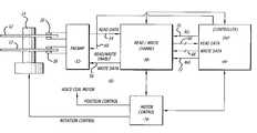
- FIG. 2is a top view of an embodiment of a hard disk drive of the present invention
- FIG. 2Ais a top enlarged view of a head of the hard disk drive
- FIG. 3is a schematic of an electrical circuit for the hard disk drive
- FIG. 4is a schematic and timing diagram for the writing and reading of data in the disk drive
- FIG. 5is a flowchart showing the determination of an offset in a head of the disk drive.
- the methoddetermines an offset time by determining the difference between a desired sync byte position and an actual sync byte position located between a preamble and a data sector of the disk. The difference corresponds to the offset between the read and write elements.
- the offset timeis subtracted from the normal time for enabling the read gate of a disk drive pre-amplifier.
- FIG. 2shows an embodiment of a hard disk drive 10 of the present invention.
- the disk drive 10may include one or more magnetic disks 12 that are rotated by a spindle motor 14 .
- the spindle motor 14may be mounted to a base plate 16 .
- the disk drive 10may further have a cover 18 that encloses the disks 12 .
- the disk drive 10may include a plurality of heads 20 located adjacent to the disks 12 . As shown in FIG. 2A the heads 20 may have separate write 22 and read elements 24 .
- the write element 22magnetizes the disk 12 to write data.
- the read element 24senses the magnetic fields of the disks 12 to read data.
- the read element 24may be constructed from a magneto-resistive material that has a resistance which varies linearly with changes in magnetic flux.
- each head 20may be gimbal mounted to a flexure arm 26 as part of a head gimbal assembly (HGA).
- the flexure arms 26are attached to an actuator arm 28 that is pivotally mounted to the base plate 16 by a bearing assembly 30 .
- a voice coil 32is attached to the actuator arm 28 .
- the voice coil 32is coupled to a magnet assembly 34 to create a voice coil motor (VCM) 36 . Providing a current to the voice coil 32 will create a torque that swings the actuator arm 28 and moves the heads 20 across the disks 12 .
- VCMvoice coil motor
- the hard disk drive 10may include a printed circuit board assembly 38 that includes a plurality of integrated circuits 40 coupled to a printed circuit board 42 .
- the printed circuit board 40is coupled to the voice coil 32 , heads 20 and spindle motor 14 by wires (not shown).
- FIG. 3shows an electrical circuit 50 for reading and writing data onto the disks 12 .
- the circuit 50may include a pre-amplifier circuit 52 that is coupled to the heads 20 .
- the pre-amplifier circuit 52has a read data channel 54 and a write data channel 56 that are connected to a read/write channel circuit 58 .
- the pre-amplifier 52also has a read/write enable gate 60 connected to a controller 64 . Data can be written onto the disks 12 , or read from the disks 12 by enabling the read/write enable gate 60 .
- the read/write channel circuit 62is connected to a controller 64 through read and write channels 66 and 68 , respectively, and read and write gates 70 and 72 , respectively.
- the read gate 70is enabled when data is to be read from the disks 12 .
- the write gate 72is to be enabled when writing data to the disks 12 .
- the controller 64may be a digital signal processor that operates in accordance with a software routine, including a routine(s) to write and read data from the disks 12 .
- the read/write channel circuit 62 and controller 64may also be connected to a motor control circuit 74 which controls the voice coil motor 36 and spindle motor 14 of the disk drive 10 .
- FIG. 4shows a track segment 100 and corresponding timing signals for writing and reading data in the disk drive 10 .
- the segment 100includes a servo address mark (SAM) 102 , a SERVO field 104 and a plurality of DATA fields 105 .
- Each DATA field 105includes a PREAMBLE 106 , a sync byte (SB) 108 and a DATA sector 110 .
- a SECTOR signalis generated at predetermined intervals after the reading of the SAM signals.
- the write gate WGcan be enabled at the trailing edge of the SECTOR signal wherein preamble data, the sync byte SB and data are written onto the disk. Because the write element is offset from the read element, a portion of the PREAMBLE is actually written prematurely. The PREAMBLE allows the read/write channel to phase lock onto the data in the DATA sector.
- the read gateis enabled a predetermined time interval before the SECTOR signal. This time interval will be referred to as the offset time t 1 .
- the time at which the read gate is enabledis determined by subtracting the offset time from a normal or non-offset time shown in phantom in FIG. 4 .
- the early enablement of the read gateallows all of the PREAMBLE to be read and allow phase lock and subsequent reading of data in the data sector.
- FIG. 5shows a flowchart for determining the offset time.
- the time interval t 2 between the SECTOR signal and the sync byte for a desired sync byte locationis already known given the parameters of the disk drive.
- the preamble, sync byte and dataare written onto the disk.
- the start time of the read gateis adjusted until the read/write channel can lock and read the sync byte.
- the time interval t 3 between the SECTOR signal and the sync byteis determined in block 154 .
- the timing differential t 2 -t 3 between the desired sync position and the actual sync positionis computed in processing block 156 .
- the offset time t 1 used to shift the read gate RG during operationis computed in block 158 based on the timing differential t 2 -t 3 .
- the offset timeis stored in memory, typically on the disk(s).
- decision block 162the head 20 is moved to an adjacent track where steps 150 - 160 are repeated, unless the head 20 is at the last track.
- steps 150 - 162are repeated for a different head unless all of the heads have been processed.
- the offset times for each head and each trackcan be stored in memory and then retrieved by the controller to shift the enablement of the read gate RG to insure that the entire PREAMBLE is read and the read/write channel acquires phase lock for subsequent data retrieval.
- the offsetwas determined by measuring the time interval between the sync byte and SECTOR signal, the actual and desired position of the sync byte may be referenced from the SAM signal.
Landscapes
- Digital Magnetic Recording (AREA)
Abstract
Description
This application is based on U.S. Provisional Application No. 60/279,136, filed on Mar. 26, 2001.
1. Field of the Invention
The present invention relates to reading data in a disk drive and compensating for an offset between a read element and a write element of a head.
2. Background Information
Hard disk drives contain a plurality of magnetic heads that are coupled to rotating disks. The heads write and read information by magnetizing and sensing the magnetic fields of the disk surfaces. There have been developed magnetic heads that have a write element for magnetizing the disks and a separate read element for sensing the magnetic fields of the disks. The read element is typically constructed from a magneto-resistive material. The magneto-resistive material has a resistance that varies with the magnetic fields of the disk. Heads with magneto-resistive read elements are commonly referred to as magneto-resistive (MR) heads.
Each head is attached to a flexure arm to create a subassembly commonly referred to as a head gimbal assembly (“HGA”). The HGA's are suspended from an actuator arm. The actuator arm has a voice coil motor that can move the heads across the surfaces of the disks.
Information is typically stored in radial tracks that extend across the surface of each disk. Each track is typically divided up into a number of segments. The voice coil motor and actuator arm can move the heads to different tracks of the disks.
FIG. 1 shows a typical sector of a disk. The sector contains a servo address mark (SAM) that provides a sync for a SERVO field. The SERVO field contains servo bits that are used to center the head on the track. A DATA field follows the servo field. The data field typically contains a preamble that is used to phase lock the circuits of the disk drive with the information on the disk.
The head is typically connected to a pre-amplifier circuit that has a read gate and a separate write gate. Enabling the write gate allows information to be written onto the disk through the write element of the head. Enabling the read gate allows information to be read from the disk through the read element.
As shown in FIG. 1, the write gate WG is typically enabled in conjunction with the trailing edge of a SECTOR signal. The preamble and data are then written onto the disk. There are typically multiple DATA sectors, wherein the process of generating a SECTOR signal and writing data is repeated. The SECTOR signals are typically generated at predetermined time intervals after the detection of the SAM signal. When reading the data the read gate RG is enabled at approximately the trailing edge of the sector signal.
The write element is typically offset from the read element of an MR head. Consequently, some of the preamble is actually written prematurely so that the read element misses a portion of the preamble during a read routine. The preamble is used to phase lock the circuits of the disk drive to allow for proper reading of the data in the subsequent DATA sector(s). Without a sufficient amount of preamble to read, the disk drive may not acquire proper phase lock. A lack of phase lock may cause errors in reading the data. This problem can be alleviated by increasing the length of the preamble so that there is enough preamble data to allow phase lock. Unfortunately, stretching the preamble reduces the storage capacity of the disk drive.
A hard disk drive that includes a head coupled to a disk. The head includes a read element offset from a write element. The drive further includes electrical circuits that enable the read element as a function of the offset.
FIG. 1 is a schematic and timing diagram showing the writing and reading of data in a disk drive of the prior art;
FIG. 2 is a top view of an embodiment of a hard disk drive of the present invention;
FIG. 2A is a top enlarged view of a head of the hard disk drive;
FIG. 3 is a schematic of an electrical circuit for the hard disk drive;
FIG. 4 is a schematic and timing diagram for the writing and reading of data in the disk drive;
FIG. 5 is a flowchart showing the determination of an offset in a head of the disk drive.
Disclosed is a method for writing and reading data in a hard disk drive and compensating for an offset between a write element and a read element of a head. The method determines an offset time by determining the difference between a desired sync byte position and an actual sync byte position located between a preamble and a data sector of the disk. The difference corresponds to the offset between the read and write elements. The offset time is subtracted from the normal time for enabling the read gate of a disk drive pre-amplifier.
Referring to the drawings more particularly by reference numbers, FIG. 2 shows an embodiment of ahard disk drive 10 of the present invention. Thedisk drive 10 may include one or moremagnetic disks 12 that are rotated by aspindle motor 14. Thespindle motor 14 may be mounted to abase plate 16. Thedisk drive 10 may further have acover 18 that encloses thedisks 12.
Thedisk drive 10 may include a plurality ofheads 20 located adjacent to thedisks 12. As shown in FIG. 2A theheads 20 may haveseparate write 22 and readelements 24. Thewrite element 22 magnetizes thedisk 12 to write data. The readelement 24 senses the magnetic fields of thedisks 12 to read data. By way of example, theread element 24 may be constructed from a magneto-resistive material that has a resistance which varies linearly with changes in magnetic flux.
Referring to FIG. 2, eachhead 20 may be gimbal mounted to aflexure arm 26 as part of a head gimbal assembly (HGA). Theflexure arms 26 are attached to anactuator arm 28 that is pivotally mounted to thebase plate 16 by a bearingassembly 30. Avoice coil 32 is attached to theactuator arm 28. Thevoice coil 32 is coupled to amagnet assembly 34 to create a voice coil motor (VCM)36. Providing a current to thevoice coil 32 will create a torque that swings theactuator arm 28 and moves theheads 20 across thedisks 12.
Thehard disk drive 10 may include a printedcircuit board assembly 38 that includes a plurality ofintegrated circuits 40 coupled to a printedcircuit board 42. The printedcircuit board 40 is coupled to thevoice coil 32, heads20 andspindle motor 14 by wires (not shown).
FIG. 3 shows anelectrical circuit 50 for reading and writing data onto thedisks 12. Thecircuit 50 may include apre-amplifier circuit 52 that is coupled to theheads 20. Thepre-amplifier circuit 52 has a readdata channel 54 and awrite data channel 56 that are connected to a read/write channel circuit 58. Thepre-amplifier 52 also has a read/write enablegate 60 connected to acontroller 64. Data can be written onto thedisks 12, or read from thedisks 12 by enabling the read/write enablegate 60.
The read/write channel circuit62 is connected to acontroller 64 through read and writechannels gates gate 70 is enabled when data is to be read from thedisks 12. Thewrite gate 72 is to be enabled when writing data to thedisks 12. Thecontroller 64 may be a digital signal processor that operates in accordance with a software routine, including a routine(s) to write and read data from thedisks 12. The read/write channel circuit62 andcontroller 64 may also be connected to amotor control circuit 74 which controls thevoice coil motor 36 andspindle motor 14 of thedisk drive 10.
FIG. 4 shows atrack segment 100 and corresponding timing signals for writing and reading data in thedisk drive 10. Thesegment 100 includes a servo address mark (SAM)102, aSERVO field 104 and a plurality of DATA fields105. EachDATA field 105 includes aPREAMBLE 106, a sync byte (SB)108 and aDATA sector 110. A SECTOR signal is generated at predetermined intervals after the reading of the SAM signals. These fields and signals are found in the prior art as shown in FIG.1.
The write gate WG can be enabled at the trailing edge of the SECTOR signal wherein preamble data, the sync byte SB and data are written onto the disk. Because the write element is offset from the read element, a portion of the PREAMBLE is actually written prematurely. The PREAMBLE allows the read/write channel to phase lock onto the data in the DATA sector.
To insure that all of the preamble data is properly read and the read/write channel acquires phase lock, the read gate is enabled a predetermined time interval before the SECTOR signal. This time interval will be referred to as the offset time t1. The time at which the read gate is enabled is determined by subtracting the offset time from a normal or non-offset time shown in phantom in FIG.4. The early enablement of the read gate allows all of the PREAMBLE to be read and allow phase lock and subsequent reading of data in the data sector.
FIG. 5 shows a flowchart for determining the offset time. The time interval t2between the SECTOR signal and the sync byte for a desired sync byte location is already known given the parameters of the disk drive. In process block150 the preamble, sync byte and data are written onto the disk. Inblock 152, the start time of the read gate is adjusted until the read/write channel can lock and read the sync byte. The time interval t3between the SECTOR signal and the sync byte is determined inblock 154. The timing differential t2-t3between the desired sync position and the actual sync position is computed inprocessing block 156.
The offset time t1used to shift the read gate RG during operation is computed inblock 158 based on the timing differential t2-t3. Inblock 160, the offset time is stored in memory, typically on the disk(s). Indecision block 162 thehead 20 is moved to an adjacent track where steps150-160 are repeated, unless thehead 20 is at the last track. Indecision block 162, steps150-162 are repeated for a different head unless all of the heads have been processed.
The offset times for each head and each track can be stored in memory and then retrieved by the controller to shift the enablement of the read gate RG to insure that the entire PREAMBLE is read and the read/write channel acquires phase lock for subsequent data retrieval.
While certain exemplary embodiments have been described and shown in the accompanying drawings, it is to be understood that such embodiments are merely illustrative of and not restrictive on the broad invention, and that this invention not be limited to the specific constructions and arrangements shown and described, since various other modifications may occur to those ordinarily skilled in the art.
For example, although the offset was determined by measuring the time interval between the sync byte and SECTOR signal, the actual and desired position of the sync byte may be referenced from the SAM signal.
Claims (47)
1. A hard disk drive, comprising:
a disk;
a spindle motor coupled to said disk;
a head coupled to said disk, said head having a read element that is separated from a write element by an offset; and,
an electrical circuit that enables said read element as a function of the offset.
2. The disk drive ofclaim 1 , wherein said disk includes a sync byte, the offset is related to a difference between a desired sync byte location and an actual sync byte location.
3. The disk drive ofclaim 2 , wherein the sync byte location is measured from a sector signal.
4. The disk drive ofclaim 2 , wherein the sync byte location is measured from a sync address mark located on said disk.
5. The disk drive ofclaim 1 , wherein said electrical circuit includes a pre-amplifier circuit connected to said head, a read/write channel connected to said pre-amplifier circuit and a controller connected to said read/write channel and said pre-amplifier, said pre-amplifier circuit having a read gate coupled to said read element of said head.
6. The disk drive ofclaim 1 , wherein the information relating to the offset is stored on said disk.
7. The disk drive ofclaim 2 , wherein said disk includes a data sector and a preamble to said data sector, said sync byte being located between said data sector and said preamble.
8. A hard disk drive, comprising:
a disk that has a sync address mark, a data sector, a preamble to said data sector, and a sync byte located between said preamble and said data sector;
a spindle motor coupled to said disk;
a head coupled to said disk, said head having a read element that is separated from a write element by an offset;
a pre-amplifier circuit connected to said head, said pre-amplifier circuit having a read gate coupled to said read element;
a read/write channel circuit connected to said pre-amplifier circuit; and,
a controller connected to read/write channel circuit and said pre-amplifier circuit, said controller provides a read gate signal to said read gate to enable said read element, a timing of said read gate signal being a function of the offset.
9. The disk drive ofclaim 8 , wherein the offset is determined from a desired sync byte location and an actual sync byte location.
10. The disk drive ofclaim 9 , wherein the actual sync byte is measured from the sync address mark.
11. The disk drive ofclaim 9 , wherein the actual sync byte is measured from a sector signal.
12. The disk drive ofclaim 11 , wherein the read gate signal is generated in accordance with a difference between a non-offset time of the read gate signal and the offset time.
13. A hard disk drive, comprising:
a disk;
a spindle motor coupled to said disk;
a head coupled to said disk, said head having a read element that is separated from a write element by an offset; and,
circuit means for enabling said read element as a function of the offset.
14. The disk drive ofclaim 13 , wherein said disk includes a sync byte, the offset is related to a difference between a desired sync byte location and an actual sync byte location.
15. The disk drive ofclaim 14 , wherein the sync byte location is measured from a sector signal.
16. The disk drive ofclaim 14 , wherein the sync byte location is measured from a sync address mark located on said disk.
17. The disk drive ofclaim 13 , wherein said circuit means includes a pre-amplifier circuit connected to said head, a read/write channel connected to said pre-amplifier circuit and a controller connected to said read/write channel and said pre-amplifier, said pre-amplifier circuit having a read gate coupled to said read element of said head.
18. The disk drive ofclaim 13 , wherein the information relating to the offset is stored on said disk.
19. The disk drive ofclaim 14 , wherein said disk includes a data sector and a preamble to said data sector, said sync byte being located between said data sector and said preamble.
20. A hard disk drive, comprising:
a disk that has a sync address mark, a data sector, a preamble to said data sector, and a sync byte located between said preamble and said data sector;
a spindle motor coupled to said disk;
a head coupled to said disk, said head having a read element that is separated from a write element by an offset;
a pre-amplifier circuit connected to said head, said pre-amplifier circuit having a read gate coupled to said read element;
a read/write channel circuit connected to said pre-amplifier circuit; and,
controller means for providing a read gate signal to said read gate to enable said read element, a timing of said read gate signal being a function of the offset.
21. The disk drive ofclaim 20 , wherein an offset time is determined from a desired sync byte location and an actual sync byte location.
22. The disk drive ofclaim 21 , wherein the actual sync byte is measured from the sync address mark.
23. The disk drive ofclaim 21 , wherein the actual sync byte is measured from a sector signal.
24. The disk drive ofclaim 21 , wherein the read gate signal is generated in accordance with a difference between a non-offset time of the read gate signal and the offset time.
25. A method for enabling a read gate of a hard disk drive, comprising:
reading a sync address mark of a disk with a head that has a read element offset from a write element;
generating a sector signal; and,
enabling a read gate signal at a time that is a function of the offset.
26. A method to determine an offset between a read element and a write element of a hard disk drive, comprising:
determining a desired sync byte location on a disk;
reading a disk with a head that has a read element;
determining an actual sync byte location of the disk; and,
generating offset information as a difference between the desired and actual sync byte locations.
27. The method ofclaim 26 , further comprising storing the offset information onto the disk.
28. The method ofclaim 26 , wherein the actual sync byte position is measured from a sync address mark.
29. The method ofclaim 26 , wherein the actual sync byte position is measured from a sector signal.
30. The method ofclaim 26 , wherein the sync byte is located between a data sector and a preamble of said data sector.
31. The method ofclaim 26 , further comprising using the offset information to enable a read gate.
32. A circuit that controls a read/write operation of a data storage device that has a read element and a write element that are physically offset from each other, comprising:
a controller that generates a periodic timing reference signal, a read gate signal that precedes in time said periodic timing reference signal and indicates a start of a read operation, and a write gate signal that is subsequent in time to said periodic timing reference signal by an offset duration and indicates a start of a write operation.
33. The circuit according to aclaim 32 , wherein said offset duration corresponds to said physical offset between said read element and said write element.
34. The circuit according toclaim 32 , wherein said controller further generates a write gate signal that is subsequent in time to said periodic timing reference signal and indicates a start of a write operation.
35. The circuit ofclaim 32 , wherein said periodic timing reference signal is a SECTOR signal.
36. A data storage device, comprising:
a storage medium;
a head coupled to said storage medium, said head having a read element that is physically offset from a write element;
a controller that generates a periodic timing reference signal, a read gate signal that precedes in time said periodic timing reference signal and indicates a start of a read operation, and a write gate signal that is subsequent in time to said periodic timing reference signal by an offset duration and indicates a start of a write operation.
37. The data storage device according toclaim 36 , wherein said offset duration corresponding to said physical offset between said read element and said write element.
38. The data storage device ofclaim 36 , wherein said periodic timing reference signal is a SECTOR signal.
39. A method for controlling the operation of a data storage device that has a read element physically offset from a write element, comprising:
generating a write signal that is subsequent in time to a first periodic timing reference signal to initiate a write operation through the write element; and,
generating a read gate signal that precedes in time a second periodic timing reference signal to initiate a read operation through the read element.
40. The method ofclaim 39 , wherein the first and second periodic timing reference signals are SECTOR signals.
41. A circuit that controls a read/write operation of a data storage device that has a read element and a write element that are physically offset from each other, comprising:
a controller that generates a periodic timing reference signal, and a read gate signal that indicates a start of a read operation, said read gate signal being offset in time from the periodic timing reference signal by a duration that corresponds to the physical offset between the read element and the write element.
42. The circuit ofclaim 41 , wherein said periodic timing reference signal is a SECTOR signal.
43. A method for controlling the read/write operation of a data storage device that has a read element and a write element that are physically offset from each other, comprising:
generating a write signal that is subsequent in time to a first periodic timing reference signal by an offset duration to initiate a write operation through the write element; and,
generating a read gate signal that precedes in time a second periodic timing reference signal to initiate a read operation through the read element.
44. The method ofclaim 43 , wherein the first and second periodic timing reference signals are SECTOR signals.
45. A method of compensating for a physical offset between a read element and a write element of a data storage device, comprising:
writing a data pattern onto a storage medium, the data pattern including a preamble portion that has a start point;
determining a time duration between the start point of the preamble and a periodic timing reference signal; and,
offsetting at least one of a read gate signal and a write gate signal from said periodic timing reference signal by said determined time duration, said read gate signal indicating a start of a read operation, said write gate signal indicating a start of a write operation.
46. The method ofclaim 45 , wherein the time duration is stored onto the storage medium.
47. The method ofclaim 45 , wherein said time duration is determined by determining a time length of said preamble portion, determining a rear time duration, said rear time duration being a time difference between said periodic timing reference signal and an end of said preamble portion, and subtracting said rear time duration from said time length to arrive at said time duration.
Priority Applications (1)
| Application Number | Priority Date | Filing Date | Title |
|---|---|---|---|
| US10/037,783US6724553B2 (en) | 2001-03-26 | 2001-10-22 | Method and apparatus for generating the optimum read timing for read and write offset of a magneto resistive head |
Applications Claiming Priority (2)
| Application Number | Priority Date | Filing Date | Title |
|---|---|---|---|
| US27913601P | 2001-03-26 | 2001-03-26 | |
| US10/037,783US6724553B2 (en) | 2001-03-26 | 2001-10-22 | Method and apparatus for generating the optimum read timing for read and write offset of a magneto resistive head |
Publications (2)
| Publication Number | Publication Date |
|---|---|
| US20020135915A1 US20020135915A1 (en) | 2002-09-26 |
| US6724553B2true US6724553B2 (en) | 2004-04-20 |
Family
ID=23067773
Family Applications (1)
| Application Number | Title | Priority Date | Filing Date |
|---|---|---|---|
| US10/037,783Expired - Fee RelatedUS6724553B2 (en) | 2001-03-26 | 2001-10-22 | Method and apparatus for generating the optimum read timing for read and write offset of a magneto resistive head |
Country Status (5)
| Country | Link |
|---|---|
| US (1) | US6724553B2 (en) |
| EP (1) | EP1267341B1 (en) |
| JP (1) | JP2002334402A (en) |
| KR (1) | KR100446296B1 (en) |
| DE (1) | DE60237940D1 (en) |
Cited By (6)
| Publication number | Priority date | Publication date | Assignee | Title |
|---|---|---|---|---|
| US20040190174A1 (en)* | 2003-03-26 | 2004-09-30 | Hitachi Global Storage Technologies Japan, Ltd. | Method for compensating timing to start data recording and magnetic disk device using same |
| US20050002295A1 (en)* | 2003-07-04 | 2005-01-06 | Kabushiki Kaisha Toshiba | Method and apparatus for measuring head gap length of composite head |
| US7006316B1 (en) | 2004-08-16 | 2006-02-28 | Western Digital Technologies, Inc. | Estimating a writer/reader gap in a disk drive by measuring write/read times relative to a sync mark |
| US20070019320A1 (en)* | 2005-07-19 | 2007-01-25 | Samsung Electronics Co., Ltd. | Recording controlling method in hard disk drive and hard disk drive using the same |
| US8749911B1 (en) | 2013-03-11 | 2014-06-10 | Western Digital Technologies, Inc. | Disk drive accounting for fractional clock cycle when measuring reader/writer gap |
| US9013818B1 (en)* | 2013-12-06 | 2015-04-21 | Western Digital Technologies, Inc. | Disk drive measuring reader/writer gap by measuring fractional clock cycle over disk radius |
Families Citing this family (2)
| Publication number | Priority date | Publication date | Assignee | Title |
|---|---|---|---|---|
| JP3987484B2 (en)* | 2003-11-28 | 2007-10-10 | 株式会社東芝 | Magnetic recording medium, magnetic recording apparatus, and offset amount measuring method |
| KR101957155B1 (en) | 2018-07-05 | 2019-03-13 | 메리츠테크놀로지 주식회사 | Soundproof Tunnel using Composite Structure |
Citations (62)
| Publication number | Priority date | Publication date | Assignee | Title |
|---|---|---|---|---|
| US3834392A (en) | 1973-02-01 | 1974-09-10 | Kli Inc | Laparoscopy system |
| US4343300A (en) | 1979-09-20 | 1982-08-10 | Olympus Optical Co., Ltd. | Data transmission system for an endoscope apparatus |
| EP0079524A1 (en) | 1981-11-04 | 1983-05-25 | Olympus Optical Co., Ltd. | Endoscope apparatus |
| US4499895A (en) | 1981-10-15 | 1985-02-19 | Olympus Optical Co., Ltd. | Endoscope system with an electric bending mechanism |
| US4572198A (en) | 1984-06-18 | 1986-02-25 | Varian Associates, Inc. | Catheter for use with NMR imaging systems |
| US4573452A (en) | 1984-07-12 | 1986-03-04 | Greenberg I Melvin | Surgical holder for a laparoscope or the like |
| US4601705A (en) | 1983-10-31 | 1986-07-22 | Mccoy William C | Steerable and aimable catheter |
| US4621618A (en) | 1984-02-28 | 1986-11-11 | Olympus Optical Company, Ltd. | Dual viewing and control apparatus for endoscope |
| US4633304A (en) | 1983-08-27 | 1986-12-30 | Olympus Optical Co., Ltd. | Endoscope assembly |
| US4672963A (en) | 1985-06-07 | 1987-06-16 | Israel Barken | Apparatus and method for computer controlled laser surgery |
| US4758222A (en) | 1985-05-03 | 1988-07-19 | Mccoy William C | Steerable and aimable catheter |
| US4785806A (en) | 1987-01-08 | 1988-11-22 | Yale University | Laser ablation process and apparatus |
| US4788975A (en) | 1987-11-05 | 1988-12-06 | Medilase, Inc. | Control system and method for improved laser angioplasty |
| US4790813A (en) | 1984-12-17 | 1988-12-13 | Intravascular Surgical Instruments, Inc. | Method and apparatus for surgically removing remote deposits |
| US4802033A (en) | 1986-11-07 | 1989-01-31 | Eastman Kodak Company | Predictive positioning offset compensation for high TPI disk systems |
| US4875897A (en) | 1981-06-12 | 1989-10-24 | Regents Of University Of California | Catheter assembly |
| US4887605A (en) | 1988-02-18 | 1989-12-19 | Angelsen Bjorn A J | Laser catheter delivery system for controlled atheroma ablation combining laser angioplasty and intra-arterial ultrasonic imagining |
| US4974607A (en) | 1987-08-20 | 1990-12-04 | Satoru Miwa | System for centralized management of medical data |
| US4982295A (en) | 1988-01-28 | 1991-01-01 | Mitsumi Electric Co., Ltd. | Method for centering a read/write head of a magnetic data storage apparatus on a track of a magnetic disk |
| US4996975A (en) | 1989-06-01 | 1991-03-05 | Kabushiki Kaisha Toshiba | Electronic endoscope apparatus capable of warning lifetime of electronic scope |
| US5078714A (en) | 1990-03-02 | 1992-01-07 | Jefferson Katims | Method and apparatus for placement of a probe in the body and the medical procedure for guiding and locating a catheter or probe in the body |
| US5104392A (en) | 1985-03-22 | 1992-04-14 | Massachusetts Institute Of Technology | Laser spectro-optic imaging for diagnosis and treatment of diseased tissue |
| US5125888A (en) | 1990-01-10 | 1992-06-30 | University Of Virginia Alumni Patents Foundation | Magnetic stereotactic system for treatment delivery |
| US5170299A (en) | 1990-08-17 | 1992-12-08 | Quantum Corporation | Edge servo for disk drive head positioner |
| US5203781A (en) | 1991-12-19 | 1993-04-20 | Meditron Devices, Inc. | Lumbar arthroscopic laser sheath |
| US5217001A (en) | 1991-12-09 | 1993-06-08 | Nakao Naomi L | Endoscope sheath and related method |
| US5217003A (en) | 1991-03-18 | 1993-06-08 | Wilk Peter J | Automated surgical system and apparatus |
| US5217453A (en) | 1991-03-18 | 1993-06-08 | Wilk Peter J | Automated surgical system and apparatus |
| US5228429A (en) | 1991-01-14 | 1993-07-20 | Tadashi Hatano | Position measuring device for endoscope |
| US5233482A (en) | 1991-07-31 | 1993-08-03 | International Business Machines Corporation | Thermal asperity compensation for PRML data detection |
| US5235478A (en) | 1989-12-15 | 1993-08-10 | Sony Corporation | Disc drive apparatus with servo tracks offset from data tracks |
| US5259365A (en) | 1989-07-26 | 1993-11-09 | Olympus Optical Co., Ltd. | Endoscope examination apparatus |
| US5268803A (en) | 1991-01-31 | 1993-12-07 | Sony Corporation | Disc memory apparatus utilizing detection of high-accuracy address data in short servo sectors for high speed accessing |
| US5274510A (en) | 1990-05-21 | 1993-12-28 | Sony Corporation | Track address pattern for a disk memory apparatus |
| US5301080A (en) | 1992-12-31 | 1994-04-05 | International Business Machines Corporation | Bias servo loop for magneto-resistive read/write head |
| US5335121A (en) | 1991-10-01 | 1994-08-02 | U.S. Philips Corporation | Arrangement for reproducing a digital signal from a track on a magnetic record carrier using a read head with magneto-resistive element and an equalizer filter |
| US5335123A (en) | 1990-02-21 | 1994-08-02 | Matsushita Electric Industrial Co., Ltd. | Apparatus and method for head-positioning on a rotatable recording medium |
| US5367409A (en) | 1993-04-29 | 1994-11-22 | International Business Machines Corporation | Even harmonic distortion compensation for digital data detection |
| US5384671A (en) | 1993-12-23 | 1995-01-24 | Quantum Corporation | PRML sampled data channel synchronous servo detector |
| US5388127A (en) | 1993-02-09 | 1995-02-07 | Hitachi America, Ltd. | Digital timing recovery circuit |
| US5402280A (en) | 1992-05-11 | 1995-03-28 | Quantum Corp. | Method and apparatus for runout correction due to disk slip or spindle imbalance |
| US5483393A (en) | 1994-04-18 | 1996-01-09 | Western Digital Corporation | Disk drive having head positioning servo with improved servo read signal processing using median servo burst peak magnitudes |
| US5497111A (en) | 1994-12-22 | 1996-03-05 | International Business Machines Corporation | Peak detection circuit for suppressing magnetoresistive thermal asperity transients in a data channel |
| US5500776A (en) | 1993-12-16 | 1996-03-19 | Seagate Technology, Inc. | Self-calibration for computer disk read/write offsets |
| US5523899A (en) | 1991-11-22 | 1996-06-04 | Micropolis Corporation | Method and apparatus for thermal calibration of hard disk drive |
| US5539714A (en) | 1991-09-25 | 1996-07-23 | Integral Peripherals | Adaptive runout compensation for miniature disk drives |
| US5566101A (en) | 1995-08-15 | 1996-10-15 | Sigmatel, Inc. | Method and apparatus for a finite impulse response filter processor |
| US5581420A (en) | 1993-03-08 | 1996-12-03 | International Business Machines Corporation | Method and system for determining a radial positioning valve used for writing tracks at a desired track pitch |
| US5587850A (en) | 1994-08-26 | 1996-12-24 | Quantum Corporation | Data track pattern including embedded servo sectors for magneto-resistive read/inductive write head structure for a disk drive |
| US5590154A (en) | 1995-06-26 | 1996-12-31 | Motorola, Inc. | Equalizer circuit and a method for equalizing a continuous signal |
| US5606469A (en) | 1992-03-30 | 1997-02-25 | Fujitsu Limited | Method for correcting offset in a magnetic disk including apparent offtrack cancellation |
| US5608587A (en) | 1993-08-06 | 1997-03-04 | Seagate Technology, Inc. | Method using magnetic disk servo pattern with buried identification patterns |
| US5715105A (en) | 1992-09-28 | 1998-02-03 | Hitachi, Ltd. | Method of and apparatus for recording on and reproducing from disk-type recording medium having recording tracks with sectors each having an ID area and a data area |
| US5781133A (en) | 1996-08-05 | 1998-07-14 | Seagate Technology, Inc. | Method and apparatus for implementing run length limited codes |
| US5822143A (en) | 1996-06-11 | 1998-10-13 | Western Digital Corporation | Decision feedback equalization implementation of partial-response signaling in a magnetic recording channel |
| US5844920A (en) | 1996-11-07 | 1998-12-01 | Cirrus Logic, Inc. | Thermal asperity compensation using multiple sync marks for retroactive and split segment data synchronization in a magnetic disk storage system |
| US5862007A (en) | 1996-04-18 | 1999-01-19 | Samsung Electronics Co., Ltd. | Method and apparatus for removing baseline shifts in a read signal using filters |
| US5898532A (en) | 1996-07-02 | 1999-04-27 | Seagate Technology Inc. | MR head thermal asperity recovery |
| US5905601A (en)* | 1995-05-16 | 1999-05-18 | Kabushiki Kaisha Toshiba | Apparatus for reproducing data having a restart read gate signal generator in a disk storage system |
| US5961658A (en) | 1997-05-23 | 1999-10-05 | Cirrus Logic, Inc. | PR4 equalization and an EPR4 remod/demod sequence detector in a sampled amplitude read channel |
| US5986847A (en) | 1996-10-18 | 1999-11-16 | Samsung Electronics Co., Ltd. | Method and apparatus for providing read and write skew offset information for a magneto-resistive head |
| US6094316A (en) | 1998-03-27 | 2000-07-25 | Samsung Electronics Co., Ltd. | Method and apparatus for providing thermal asperity compensation in a fixed delay tree search detector |
Family Cites Families (10)
| Publication number | Priority date | Publication date | Assignee | Title |
|---|---|---|---|---|
| JPH02232807A (en)* | 1989-03-07 | 1990-09-14 | Fujitsu Ltd | Method for measuring circumferential offset amount in magnetic disk device |
| US5168395A (en)* | 1990-05-02 | 1992-12-01 | International Business Machines Corporation | Controlled magnetic recording head relaxation in a magnetic recording system |
| JPH06176486A (en)* | 1992-11-30 | 1994-06-24 | Sony Corp | Magnetic disk device and magnetic disk |
| US5751512A (en)* | 1994-01-28 | 1998-05-12 | Seagate Technology, Inc. | Data storage format for data storage devices having a radial offset between read and write elements |
| JP3890090B2 (en)* | 1995-10-16 | 2007-03-07 | 株式会社日立グローバルストレージテクノロジーズ | Magnetic disk unit |
| US5850566A (en)* | 1995-12-13 | 1998-12-15 | International Business Machines Corporation | Method for storing multiple files without header information and for each storage medium maintaining a separate stored index including header information for each file |
| US5867343A (en) | 1996-05-01 | 1999-02-02 | Samsung Electronics, Ltd. | Method and apparatus for storing position offset information on a hard drive assembly cylinder |
| US5917670A (en)* | 1996-10-15 | 1999-06-29 | Quantum Corporation | Method for recovering data from disk with magneto-resistive head in presence of thermal asperities |
| JPH113565A (en)* | 1997-06-11 | 1999-01-06 | Hitachi Ltd | Data recording / reproducing method and apparatus therefor |
| JP4026989B2 (en)* | 1999-07-08 | 2007-12-26 | 富士通株式会社 | Magnetic disk drive and optimum offset measuring method |
- 2001
- 2001-10-22USUS10/037,783patent/US6724553B2/ennot_activeExpired - Fee Related
- 2002
- 2002-03-26JPJP2002085840Apatent/JP2002334402A/enactivePending
- 2002-03-26DEDE60237940Tpatent/DE60237940D1/ennot_activeExpired - Lifetime
- 2002-03-26EPEP02006901Apatent/EP1267341B1/ennot_activeExpired - Lifetime
- 2002-03-26KRKR10-2002-0016474Apatent/KR100446296B1/ennot_activeExpired - Fee Related
Patent Citations (65)
| Publication number | Priority date | Publication date | Assignee | Title |
|---|---|---|---|---|
| US3834392A (en) | 1973-02-01 | 1974-09-10 | Kli Inc | Laparoscopy system |
| US4343300A (en) | 1979-09-20 | 1982-08-10 | Olympus Optical Co., Ltd. | Data transmission system for an endoscope apparatus |
| US4875897A (en) | 1981-06-12 | 1989-10-24 | Regents Of University Of California | Catheter assembly |
| US4499895A (en) | 1981-10-15 | 1985-02-19 | Olympus Optical Co., Ltd. | Endoscope system with an electric bending mechanism |
| EP0079524A1 (en) | 1981-11-04 | 1983-05-25 | Olympus Optical Co., Ltd. | Endoscope apparatus |
| US4633304A (en) | 1983-08-27 | 1986-12-30 | Olympus Optical Co., Ltd. | Endoscope assembly |
| US4601705A (en) | 1983-10-31 | 1986-07-22 | Mccoy William C | Steerable and aimable catheter |
| US4621618A (en) | 1984-02-28 | 1986-11-11 | Olympus Optical Company, Ltd. | Dual viewing and control apparatus for endoscope |
| US4572198A (en) | 1984-06-18 | 1986-02-25 | Varian Associates, Inc. | Catheter for use with NMR imaging systems |
| US4573452A (en) | 1984-07-12 | 1986-03-04 | Greenberg I Melvin | Surgical holder for a laparoscope or the like |
| US4790813A (en) | 1984-12-17 | 1988-12-13 | Intravascular Surgical Instruments, Inc. | Method and apparatus for surgically removing remote deposits |
| US5104392A (en) | 1985-03-22 | 1992-04-14 | Massachusetts Institute Of Technology | Laser spectro-optic imaging for diagnosis and treatment of diseased tissue |
| US4758222A (en) | 1985-05-03 | 1988-07-19 | Mccoy William C | Steerable and aimable catheter |
| US4672963A (en) | 1985-06-07 | 1987-06-16 | Israel Barken | Apparatus and method for computer controlled laser surgery |
| US4802033A (en) | 1986-11-07 | 1989-01-31 | Eastman Kodak Company | Predictive positioning offset compensation for high TPI disk systems |
| US4785806A (en) | 1987-01-08 | 1988-11-22 | Yale University | Laser ablation process and apparatus |
| US4974607A (en) | 1987-08-20 | 1990-12-04 | Satoru Miwa | System for centralized management of medical data |
| US4788975A (en) | 1987-11-05 | 1988-12-06 | Medilase, Inc. | Control system and method for improved laser angioplasty |
| US4788975B1 (en) | 1987-11-05 | 1999-03-02 | Trimedyne Inc | Control system and method for improved laser angioplasty |
| US4982295A (en) | 1988-01-28 | 1991-01-01 | Mitsumi Electric Co., Ltd. | Method for centering a read/write head of a magnetic data storage apparatus on a track of a magnetic disk |
| US4887605A (en) | 1988-02-18 | 1989-12-19 | Angelsen Bjorn A J | Laser catheter delivery system for controlled atheroma ablation combining laser angioplasty and intra-arterial ultrasonic imagining |
| US4996975A (en) | 1989-06-01 | 1991-03-05 | Kabushiki Kaisha Toshiba | Electronic endoscope apparatus capable of warning lifetime of electronic scope |
| US5259365A (en) | 1989-07-26 | 1993-11-09 | Olympus Optical Co., Ltd. | Endoscope examination apparatus |
| US5235478A (en) | 1989-12-15 | 1993-08-10 | Sony Corporation | Disc drive apparatus with servo tracks offset from data tracks |
| US5125888A (en) | 1990-01-10 | 1992-06-30 | University Of Virginia Alumni Patents Foundation | Magnetic stereotactic system for treatment delivery |
| US5335123A (en) | 1990-02-21 | 1994-08-02 | Matsushita Electric Industrial Co., Ltd. | Apparatus and method for head-positioning on a rotatable recording medium |
| US5078714A (en) | 1990-03-02 | 1992-01-07 | Jefferson Katims | Method and apparatus for placement of a probe in the body and the medical procedure for guiding and locating a catheter or probe in the body |
| US5274510A (en) | 1990-05-21 | 1993-12-28 | Sony Corporation | Track address pattern for a disk memory apparatus |
| US5170299A (en) | 1990-08-17 | 1992-12-08 | Quantum Corporation | Edge servo for disk drive head positioner |
| US5228429A (en) | 1991-01-14 | 1993-07-20 | Tadashi Hatano | Position measuring device for endoscope |
| US5268803A (en) | 1991-01-31 | 1993-12-07 | Sony Corporation | Disc memory apparatus utilizing detection of high-accuracy address data in short servo sectors for high speed accessing |
| US5217453A (en) | 1991-03-18 | 1993-06-08 | Wilk Peter J | Automated surgical system and apparatus |
| US5217003A (en) | 1991-03-18 | 1993-06-08 | Wilk Peter J | Automated surgical system and apparatus |
| US5368015A (en) | 1991-03-18 | 1994-11-29 | Wilk; Peter J. | Automated surgical system and apparatus |
| US5233482A (en) | 1991-07-31 | 1993-08-03 | International Business Machines Corporation | Thermal asperity compensation for PRML data detection |
| US5539714A (en) | 1991-09-25 | 1996-07-23 | Integral Peripherals | Adaptive runout compensation for miniature disk drives |
| US5335121A (en) | 1991-10-01 | 1994-08-02 | U.S. Philips Corporation | Arrangement for reproducing a digital signal from a track on a magnetic record carrier using a read head with magneto-resistive element and an equalizer filter |
| US5523899A (en) | 1991-11-22 | 1996-06-04 | Micropolis Corporation | Method and apparatus for thermal calibration of hard disk drive |
| US5217001A (en) | 1991-12-09 | 1993-06-08 | Nakao Naomi L | Endoscope sheath and related method |
| US5203781A (en) | 1991-12-19 | 1993-04-20 | Meditron Devices, Inc. | Lumbar arthroscopic laser sheath |
| US5606469A (en) | 1992-03-30 | 1997-02-25 | Fujitsu Limited | Method for correcting offset in a magnetic disk including apparent offtrack cancellation |
| US5402280A (en) | 1992-05-11 | 1995-03-28 | Quantum Corp. | Method and apparatus for runout correction due to disk slip or spindle imbalance |
| US5715105A (en) | 1992-09-28 | 1998-02-03 | Hitachi, Ltd. | Method of and apparatus for recording on and reproducing from disk-type recording medium having recording tracks with sectors each having an ID area and a data area |
| US5301080A (en) | 1992-12-31 | 1994-04-05 | International Business Machines Corporation | Bias servo loop for magneto-resistive read/write head |
| US5388127A (en) | 1993-02-09 | 1995-02-07 | Hitachi America, Ltd. | Digital timing recovery circuit |
| US5615058A (en) | 1993-03-08 | 1997-03-25 | International Business Machines Corporation | Method and system for writing a servo-pattern on a storage medium |
| US5581420A (en) | 1993-03-08 | 1996-12-03 | International Business Machines Corporation | Method and system for determining a radial positioning valve used for writing tracks at a desired track pitch |
| US5367409A (en) | 1993-04-29 | 1994-11-22 | International Business Machines Corporation | Even harmonic distortion compensation for digital data detection |
| US5608587A (en) | 1993-08-06 | 1997-03-04 | Seagate Technology, Inc. | Method using magnetic disk servo pattern with buried identification patterns |
| US5500776A (en) | 1993-12-16 | 1996-03-19 | Seagate Technology, Inc. | Self-calibration for computer disk read/write offsets |
| US5384671A (en) | 1993-12-23 | 1995-01-24 | Quantum Corporation | PRML sampled data channel synchronous servo detector |
| US5483393A (en) | 1994-04-18 | 1996-01-09 | Western Digital Corporation | Disk drive having head positioning servo with improved servo read signal processing using median servo burst peak magnitudes |
| US5587850A (en) | 1994-08-26 | 1996-12-24 | Quantum Corporation | Data track pattern including embedded servo sectors for magneto-resistive read/inductive write head structure for a disk drive |
| US5497111A (en) | 1994-12-22 | 1996-03-05 | International Business Machines Corporation | Peak detection circuit for suppressing magnetoresistive thermal asperity transients in a data channel |
| US5905601A (en)* | 1995-05-16 | 1999-05-18 | Kabushiki Kaisha Toshiba | Apparatus for reproducing data having a restart read gate signal generator in a disk storage system |
| US5590154A (en) | 1995-06-26 | 1996-12-31 | Motorola, Inc. | Equalizer circuit and a method for equalizing a continuous signal |
| US5566101A (en) | 1995-08-15 | 1996-10-15 | Sigmatel, Inc. | Method and apparatus for a finite impulse response filter processor |
| US5862007A (en) | 1996-04-18 | 1999-01-19 | Samsung Electronics Co., Ltd. | Method and apparatus for removing baseline shifts in a read signal using filters |
| US5822143A (en) | 1996-06-11 | 1998-10-13 | Western Digital Corporation | Decision feedback equalization implementation of partial-response signaling in a magnetic recording channel |
| US5898532A (en) | 1996-07-02 | 1999-04-27 | Seagate Technology Inc. | MR head thermal asperity recovery |
| US5781133A (en) | 1996-08-05 | 1998-07-14 | Seagate Technology, Inc. | Method and apparatus for implementing run length limited codes |
| US5986847A (en) | 1996-10-18 | 1999-11-16 | Samsung Electronics Co., Ltd. | Method and apparatus for providing read and write skew offset information for a magneto-resistive head |
| US5844920A (en) | 1996-11-07 | 1998-12-01 | Cirrus Logic, Inc. | Thermal asperity compensation using multiple sync marks for retroactive and split segment data synchronization in a magnetic disk storage system |
| US5961658A (en) | 1997-05-23 | 1999-10-05 | Cirrus Logic, Inc. | PR4 equalization and an EPR4 remod/demod sequence detector in a sampled amplitude read channel |
| US6094316A (en) | 1998-03-27 | 2000-07-25 | Samsung Electronics Co., Ltd. | Method and apparatus for providing thermal asperity compensation in a fixed delay tree search detector |
Cited By (9)
| Publication number | Priority date | Publication date | Assignee | Title |
|---|---|---|---|---|
| US20040190174A1 (en)* | 2003-03-26 | 2004-09-30 | Hitachi Global Storage Technologies Japan, Ltd. | Method for compensating timing to start data recording and magnetic disk device using same |
| US7106534B2 (en)* | 2003-03-26 | 2006-09-12 | Hitachi Global Storage Technologies Japan, Ltd. | Method for compensating timing to start data recording and magnetic disk device using same |
| US20050002295A1 (en)* | 2003-07-04 | 2005-01-06 | Kabushiki Kaisha Toshiba | Method and apparatus for measuring head gap length of composite head |
| US7388817B2 (en)* | 2003-07-04 | 2008-06-17 | Kabushiki Kaisha Toshiba | Method and apparatus for measuring head gap length of composite head |
| US7006316B1 (en) | 2004-08-16 | 2006-02-28 | Western Digital Technologies, Inc. | Estimating a writer/reader gap in a disk drive by measuring write/read times relative to a sync mark |
| US20070019320A1 (en)* | 2005-07-19 | 2007-01-25 | Samsung Electronics Co., Ltd. | Recording controlling method in hard disk drive and hard disk drive using the same |
| US7499237B2 (en)* | 2005-07-19 | 2009-03-03 | Samsung Electronics Co., Ltd. | Recording controlling method in hard disk drive and hard disk drive using the same |
| US8749911B1 (en) | 2013-03-11 | 2014-06-10 | Western Digital Technologies, Inc. | Disk drive accounting for fractional clock cycle when measuring reader/writer gap |
| US9013818B1 (en)* | 2013-12-06 | 2015-04-21 | Western Digital Technologies, Inc. | Disk drive measuring reader/writer gap by measuring fractional clock cycle over disk radius |
Also Published As
| Publication number | Publication date |
|---|---|
| DE60237940D1 (en) | 2010-11-25 |
| KR100446296B1 (en) | 2004-08-30 |
| EP1267341A3 (en) | 2007-10-24 |
| JP2002334402A (en) | 2002-11-22 |
| EP1267341B1 (en) | 2010-10-13 |
| EP1267341A2 (en) | 2002-12-18 |
| US20020135915A1 (en) | 2002-09-26 |
| KR20020076179A (en) | 2002-10-09 |
Similar Documents
| Publication | Publication Date | Title |
|---|---|---|
| US7158336B2 (en) | Window timing adjustment for spiral bursts | |
| US5867353A (en) | Off-track PES calibration for a magneto-resistive element | |
| KR100468767B1 (en) | Method for preventing adjacent track erase in HDD and apparatus thereof | |
| US7117399B2 (en) | Method of and apparatus for controlling data storage system according to temperature, and medium | |
| US6791775B2 (en) | Method and apparatus to distinguish effects of adjacent track encroachment from head thermal movement | |
| KR100855986B1 (en) | Method of generating skew table for head and hard disk drive having processor for performing the method | |
| EP1396846B1 (en) | Method and apparatus for controlling hard disc drive | |
| JP2006085832A (en) | Recording current control method and magnetic disk apparatus | |
| US7253985B1 (en) | Delay clock track read back data to compensate time variance due to disk thermal expansion in spiral servo track writing | |
| US6724553B2 (en) | Method and apparatus for generating the optimum read timing for read and write offset of a magneto resistive head | |
| US7944641B2 (en) | Overshoot duration range selection in a hard disk drive | |
| US7880991B2 (en) | Write timing system for hard disk drives with bit patterned media | |
| US20020036859A1 (en) | Method and disc drive for writing servo wedges | |
| US7423831B2 (en) | Utilization of the acceleration zone in ammonite servo writing | |
| US20050174672A1 (en) | Compensation for jitter in servo signal within data storage device | |
| US20040085669A1 (en) | Method and apparatus for providing a marker for adaptive formatting via a self-servowrite process | |
| US7649705B2 (en) | Data read retry with read timing adjustment for eccentrity of disc in data storage device | |
| KR100604859B1 (en) | Servo Timing Control Method and Disk Drive Using the Same | |
| US7203016B2 (en) | Method of reproducing data and control device using controllable dummy read gate | |
| US7859783B2 (en) | Increased format efficiency using disk synchronized write | |
| US20110032636A1 (en) | Enhanced head skew optimization for high speed disk access | |
| US8169732B2 (en) | Reducing written-in errors in servo patterns | |
| US7369344B2 (en) | Method and apparatus for compensating for offset of disk drive | |
| US20060103964A1 (en) | Variable control of write parameters for hard disk drive |
Legal Events
| Date | Code | Title | Description |
|---|---|---|---|
| AS | Assignment | Owner name:SAMSUNG ELECTRONICS CO., LTD., KOREA, REPUBLIC OF Free format text:ASSIGNMENT OF ASSIGNORS INTEREST;ASSIGNORS:YUN, JONG YUN;LEE, KANG SEOK;CHU, SANG HOON;AND OTHERS;REEL/FRAME:012449/0865 Effective date:20011018 | |
| REMI | Maintenance fee reminder mailed | ||
| LAPS | Lapse for failure to pay maintenance fees | ||
| STCH | Information on status: patent discontinuation | Free format text:PATENT EXPIRED DUE TO NONPAYMENT OF MAINTENANCE FEES UNDER 37 CFR 1.362 | |
| FP | Lapsed due to failure to pay maintenance fee | Effective date:20080420 |