US6723597B2 - Method of using high-k dielectric materials to reduce soft errors in SRAM memory cells, and a device comprising same - Google Patents
Method of using high-k dielectric materials to reduce soft errors in SRAM memory cells, and a device comprising sameDownload PDFInfo
- Publication number
- US6723597B2 US6723597B2US10/191,833US19183302AUS6723597B2US 6723597 B2US6723597 B2US 6723597B2US 19183302 AUS19183302 AUS 19183302AUS 6723597 B2US6723597 B2US 6723597B2
- Authority
- US
- United States
- Prior art keywords
- forming
- bpsg
- layer
- bpsg layer
- transistors
- Prior art date
- Legal status (The legal status is an assumption and is not a legal conclusion. Google has not performed a legal analysis and makes no representation as to the accuracy of the status listed.)
- Expired - Lifetime
Links
- 238000000034methodMethods0.000titleclaimsabstractdescription121
- 239000003989dielectric materialSubstances0.000titledescription4
- 239000000758substrateSubstances0.000claimsabstractdescription32
- 239000000463materialSubstances0.000claimsabstractdescription21
- 230000008569processEffects0.000claimsdescription58
- 238000000151depositionMethods0.000claimsdescription25
- 238000005530etchingMethods0.000claimsdescription20
- 238000000623plasma-assisted chemical vapour depositionMethods0.000claimsdescription16
- ZOXJGFHDIHLPTG-UHFFFAOYSA-NBoronChemical compound[B]ZOXJGFHDIHLPTG-UHFFFAOYSA-N0.000claimsdescription15
- 229910052796boronInorganic materials0.000claimsdescription15
- 239000005360phosphosilicate glassSubstances0.000claimsdescription15
- 238000005229chemical vapour depositionMethods0.000claimsdescription12
- WFKWXMTUELFFGS-UHFFFAOYSA-NtungstenChemical compound[W]WFKWXMTUELFFGS-UHFFFAOYSA-N0.000claimsdescription9
- 229910052721tungstenInorganic materials0.000claimsdescription9
- 239000010937tungstenSubstances0.000claimsdescription9
- TWNQGVIAIRXVLR-UHFFFAOYSA-Noxo(oxoalumanyloxy)alumaneChemical compoundO=[Al]O[Al]=OTWNQGVIAIRXVLR-UHFFFAOYSA-N0.000claimsdescription8
- BPUBBGLMJRNUCC-UHFFFAOYSA-Noxygen(2-);tantalum(5+)Chemical compound[O-2].[O-2].[O-2].[O-2].[O-2].[Ta+5].[Ta+5]BPUBBGLMJRNUCC-UHFFFAOYSA-N0.000claimsdescription8
- 229910021420polycrystalline siliconInorganic materials0.000claimsdescription8
- PBCFLUZVCVVTBY-UHFFFAOYSA-Ntantalum pentoxideInorganic materialsO=[Ta](=O)O[Ta](=O)=OPBCFLUZVCVVTBY-UHFFFAOYSA-N0.000claimsdescription8
- RVTZCBVAJQQJTK-UHFFFAOYSA-Noxygen(2-);zirconium(4+)Chemical compound[O-2].[O-2].[Zr+4]RVTZCBVAJQQJTK-UHFFFAOYSA-N0.000claimsdescription7
- 229920005591polysiliconPolymers0.000claimsdescription7
- 229910001928zirconium oxideInorganic materials0.000claimsdescription7
- RYGMFSIKBFXOCR-UHFFFAOYSA-NCopperChemical compound[Cu]RYGMFSIKBFXOCR-UHFFFAOYSA-N0.000claimsdescription6
- 229910052782aluminiumInorganic materials0.000claimsdescription6
- XAGFODPZIPBFFR-UHFFFAOYSA-NaluminiumChemical compound[Al]XAGFODPZIPBFFR-UHFFFAOYSA-N0.000claimsdescription6
- 229910052802copperInorganic materials0.000claimsdescription6
- 239000010949copperSubstances0.000claimsdescription6
- 229910052751metalInorganic materials0.000claimsdescription6
- 239000002184metalSubstances0.000claimsdescription6
- 229910001092metal group alloyInorganic materials0.000claimsdescription6
- 238000004528spin coatingMethods0.000claimsdescription5
- 238000000231atomic layer depositionMethods0.000claims5
- 229910000449hafnium oxideInorganic materials0.000claims5
- WIHZLLGSGQNAGK-UHFFFAOYSA-Nhafnium(4+);oxygen(2-)Chemical compound[O-2].[O-2].[Hf+4]WIHZLLGSGQNAGK-UHFFFAOYSA-N0.000claims5
- 239000005380borophosphosilicate glassSubstances0.000abstract7
- 230000001681protective effectEffects0.000description7
- 238000012545processingMethods0.000description6
- 239000002245particleSubstances0.000description5
- 239000004065semiconductorSubstances0.000description5
- VYPSYNLAJGMNEJ-UHFFFAOYSA-NSilicium dioxideChemical compoundO=[Si]=OVYPSYNLAJGMNEJ-UHFFFAOYSA-N0.000description4
- XUIMIQQOPSSXEZ-UHFFFAOYSA-NSiliconChemical compound[Si]XUIMIQQOPSSXEZ-UHFFFAOYSA-N0.000description4
- 230000008021depositionEffects0.000description4
- 238000009413insulationMethods0.000description4
- 229910052710siliconInorganic materials0.000description4
- 239000010703siliconSubstances0.000description4
- RTAQQCXQSZGOHL-UHFFFAOYSA-NTitaniumChemical compound[Ti]RTAQQCXQSZGOHL-UHFFFAOYSA-N0.000description3
- NRTOMJZYCJJWKI-UHFFFAOYSA-NTitanium nitrideChemical compound[Ti]#NNRTOMJZYCJJWKI-UHFFFAOYSA-N0.000description3
- 230000015572biosynthetic processEffects0.000description3
- 238000005137deposition processMethods0.000description3
- 239000010936titaniumSubstances0.000description3
- 229910052719titaniumInorganic materials0.000description3
- 229910052581Si3N4Inorganic materials0.000description2
- 230000008901benefitEffects0.000description2
- 238000010276constructionMethods0.000description2
- 238000011161developmentMethods0.000description2
- 239000002019doping agentSubstances0.000description2
- 239000007943implantSubstances0.000description2
- 238000002955isolationMethods0.000description2
- 238000004519manufacturing processMethods0.000description2
- 238000012986modificationMethods0.000description2
- 230000004048modificationEffects0.000description2
- 238000000206photolithographyMethods0.000description2
- 235000012239silicon dioxideNutrition0.000description2
- 239000000377silicon dioxideSubstances0.000description2
- HQVNEWCFYHHQES-UHFFFAOYSA-Nsilicon nitrideChemical compoundN12[Si]34N5[Si]62N3[Si]51N64HQVNEWCFYHHQES-UHFFFAOYSA-N0.000description2
- 125000006850spacer groupChemical group0.000description2
- 239000000126substanceSubstances0.000description2
- ZSLUVFAKFWKJRC-IGMARMGPSA-N232ThChemical compound[232Th]ZSLUVFAKFWKJRC-IGMARMGPSA-N0.000description1
- BOTDANWDWHJENH-UHFFFAOYSA-NTetraethyl orthosilicateChemical compoundCCO[Si](OCC)(OCC)OCCBOTDANWDWHJENH-UHFFFAOYSA-N0.000description1
- 229910052776ThoriumInorganic materials0.000description1
- 229910052770UraniumInorganic materials0.000description1
- 230000004888barrier functionEffects0.000description1
- 238000013461designMethods0.000description1
- 238000001035dryingMethods0.000description1
- -1e.g.Substances0.000description1
- 229910052732germaniumInorganic materials0.000description1
- GNPVGFCGXDBREM-UHFFFAOYSA-Ngermanium atomChemical compound[Ge]GNPVGFCGXDBREM-UHFFFAOYSA-N0.000description1
- CJNBYAVZURUTKZ-UHFFFAOYSA-Nhafnium(iv) oxideChemical compoundO=[Hf]=OCJNBYAVZURUTKZ-UHFFFAOYSA-N0.000description1
- 239000012535impuritySubstances0.000description1
- 239000012212insulatorSubstances0.000description1
- 230000010354integrationEffects0.000description1
- 230000005865ionizing radiationEffects0.000description1
- 150000002500ionsChemical class0.000description1
- 239000000203mixtureSubstances0.000description1
- 239000005022packaging materialSubstances0.000description1
- 238000005498polishingMethods0.000description1
- 238000007517polishing processMethods0.000description1
- 230000002285radioactive effectEffects0.000description1
- 230000009467reductionEffects0.000description1
- 230000003068static effectEffects0.000description1
- JFALSRSLKYAFGM-UHFFFAOYSA-Nuranium(0)Chemical compound[U]JFALSRSLKYAFGM-UHFFFAOYSA-N0.000description1
Images


Classifications
- H—ELECTRICITY
- H10—SEMICONDUCTOR DEVICES; ELECTRIC SOLID-STATE DEVICES NOT OTHERWISE PROVIDED FOR
- H10B—ELECTRONIC MEMORY DEVICES
- H10B10/00—Static random access memory [SRAM] devices
- H—ELECTRICITY
- H10—SEMICONDUCTOR DEVICES; ELECTRIC SOLID-STATE DEVICES NOT OTHERWISE PROVIDED FOR
- H10B—ELECTRONIC MEMORY DEVICES
- H10B10/00—Static random access memory [SRAM] devices
- H10B10/12—Static random access memory [SRAM] devices comprising a MOSFET load element
Definitions
- This present inventionis generally directed to the field of integrated circuits and semiconductor processing, and, more particularly, to a method of using high-k dielectric materials to reduce soft errors in static random access memory (SRAM) memory cells, and a device comprising same.
- SRAMstatic random access memory
- an SRAM memory cellprovides a very fast read access speed. Accordingly, SRAM cells are widely used in integrated circuits.
- An SRAM cellis considered to be a bi-stable circuit because it has two stable or self-maintaining operating states that correspond to two different output voltages, or logic states. Typically, the different voltages correspond to a binary stored “1” (logically high) or “0” (logically low). Without external stimuli, an SRAM memory cell will operate continuously in a single one of its two operating states. It has internal feedback to maintain a stable voltage differential between two nodes of the cell. The polarity of this voltage difference is sensed by external circuitry to determine the operating state of the SRAM cell. The two possible output voltages produced by an SRAM cell are typically determined by the upper and lower circuit supply voltages.
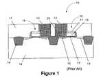
- FIG. 1is a cross-sectional view of a portion of an illustrative SRAM cell 10 formed above a semiconducting substrate 12 , such as silicon.
- the SRAM cell 10is generally comprised of two transistors 16 , each of which is comprised of a gate insulation layer 17 , a gate electrode 19 , a protective cap layer 21 , and a plurality of source/drain regions 15 .
- the transistors 16are formed between isolation structures 14 formed in the substrate 12 .
- a plurality of local interconnects 13are formed in a BPSG (boron phosphosilicate glass) layer 11 .
- BPSGboron phosphosilicate glass
- the BPSG layer 11may be formed by a variety of deposition techniques, e.g., chemical vapor deposition (“CVD”), plasma enhanced chemical vapor deposition (“PECVD”), etc.
- the thickness of the BPSG layer 11may vary depending upon the device under construction. Typically, the BPSG layer 11 may have a thickness that ranges from approximately 500-1000 nm (5000-10000 ⁇ ). More importantly, in traditional SRAM cells, the local interconnects 13 are positioned within the insulating BPSG layer 11 .
- the BPSG layer 11will be deposited and a plurality of openings 25 will be formed therein by performing known photolithography and etching techniques. Thereafter, the local intcrconnects 13 will be formed in the openings 25 in the BPSG layer 11 .
- Alpha particlesare naturally occurring ionizing radiation which can penetrate into the silicon substrate of the SRAM cell 10 depicted in FIG. 1 and generate electron-hole pairs.
- One source of alpha particlesis the decay of radioactive impurities such as uranium or thorium, known to be present in trace levels in common semiconductor packaging materials.
- the alpha particles, from whatever source,can generate sufficient charge adjacent an SRAM memory cell node to upset the data state of the SRAM memory cell, i.e., it can cause the SRAM cell 10 to flip from a “1” to a “0,” or vice versa.
- Such eventsare termed “soft errors” in the industry. Soft error rates must be controlled to very low levels for reliable operation of semiconductor devices.
- the boron element used in the BPSG layer 11is B 10 , which has a relatively large capture cross-section.
- B 10phosphosilicate glass
- the alpha particles striking the BPSG layer 11tend to split and enter the silicon with the tendency to thereby cause soft errors.
- PSGphosphosilicate glass
- the present inventionis directed to a device and various methods that may solve, or at least reduce, some or all of the aforementioned problems.
- the present inventionis generally directed to a method of using high-k dielectric materials to reduce soft errors in SRAM devices, and a device comprising same.
- the methodcomprises forming a plurality of transistors above a semiconducting substrate, forming a layer comprised of boron phosphosilicate glass (BPSG) above the substrate and the transistors, forming a dielectric layer above the BPSG layer, the dielectric layer comprised of a material having a dielectric constant greater than approximately 6.0, forming a plurality of openings in the dielectric layer and the BPSG layer, each of the openings allowing contact to a doped region of one of the transistors, and forming a conductive local interconnect (LI) in each of the openings.
- BPSGboron phosphosilicate glass
- the methodcomprises forming a plurality of transistors above a semiconducting substrate, forming a layer comprised of boron phosphosilicate glass (BPSG) above the substrate and between the transistors, forming a plurality of openings in the BPSG layer, each of the openings allowing contact to a doped region of one of the transistors, forming a conductive local interconnect in each of the openings, reducing a thickness of the BPSG layer after the local interconnects are formed, and forming a dielectric layer above the BPSG layer and between the local interconnects.
- BPSGboron phosphosilicate glass
- a memory cellcomprises a plurality of transistors formed above a semiconducting substrate and a plurality of local interconnects, each of which is conductively coupled to a doped region, i.e., a source/drain region, of one of the transistors.
- the local interconnectsare positioned in openings in a layer of boron phosphosilicate glass (BPSG) and a dielectric layer positioned above the BPSG layer, the dielectric layer being comprised of a material having a dielectric constant greater than approximately 6.0.
- BPSGboron phosphosilicate glass
- FIG. 1is a cross-sectional view of an illustrative prior art SRAM device
- FIGS. 2A-2Ddepict one illustrative process flow that may be performed in accordance with one embodiment of the present invention.
- FIGS. 3A-3Ddepict another illustrative process flow that may be performed in accordance with one illustrative embodiment of the present invention.
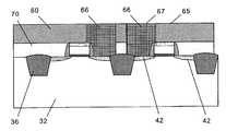
- FIGS. 2A-2DOne illustrative process flow that may be employed to manufacture an integrated circuit device in accordance with one embodiment of the present invention is depicted in FIGS. 2A-2D.
- an illustrative SRAM cell 30(see FIG. 2D) is formed above a semiconducting substrate 32 .
- the processbegins with the formation of a plurality of transistors 34 above the substrate 32 between isolation regions 36 formed in the substrate 32 .
- the transistors 34are comprised of a gate insulation layer 37 , a gate electrode 39 , sidewall spacers 40 , and source/drain regions 42 .
- a protective, cap layer 44is formed above the gate electrode 39 .
- the various components just describedmay be formed by a variety of known techniques, and they may be comprised of a variety of known materials.
- the gate insulation layer 37may be comprised of a thermally grown layer of silicon dioxide.
- the gate electrode 39may be comprised of a doped polycrystalline silicon (polysilicon), and the sidewall spacers 40 may be comprised of silicon nitride, or other like materials.
- the cap layer 44may be comprised of silicon nitride or silicon dioxide made using TEOS.
- the source/drain regions 42may be formed by performing one or more ion implant processes to implant the appropriate dopant atoms into the substrate. One or more anneal processes may then be performed to activate the implanted dopant material.
- the substrate 32may be comprised of a variety of semiconducting materials, e.g., silicon, germanium, silicon-on-insulator (SOI) structures, etc.
- SOIsilicon-on-insulator
- the initial step in the illustrative embodiment of the present invention depicted in FIGS. 2A-2Dinvolves the formation of a layer 50 of boron phosphosilicate glass (BPSG) above the transistors 34 and the substrate 32 .
- BPSG layer 50may be formed by a variety of known deposition processes, e.g., chemical vapor deposition (“CVD”), plasma enhanced chemical vapor deposition (“PECVD”), etc.
- CVDchemical vapor deposition
- PECVDplasma enhanced chemical vapor deposition
- the thickness of the BPSG layer 50may vary to some degree, but it will generally be significantly less than the BPSG layer described in the background section of the application.
- the BPSG layer 50may have a thickness that is approximately the same as the height of the gate stack, i.e., the combined height of the gate insulation layer 37 , gate electrode 39 and protective cap layer 44 .
- the BPSG layer 50has a thickness that ranges from approximately 150-200 nm (1500-2000 ⁇ ). In general, the thickness of the BPSG layer 50 will be such that the surface 52 of the BPSG layer 50 extends somewhat above the surface 46 of the protective cap layer 44 , as shown in FIG. 2 A.
- the BPSG layer 50will be deposited such that the upper surface 52 extends approximately 50-100 nm (500-1000 ⁇ ) above the upper surface 46 of the transistors.
- the surface 52 of the BPSG layer 50may be deposited in such a manner that the surface 52 is approximately level with the surface 46 after the deposition process.
- CMPchemical mechanical polishing
- an insulating layer 60comprised of a material having a relatively high dielectric constant, e.g., a dielectric constant greater than approximately 6.0 is formed above the BPSG layer 50 .
- the high-k dielectric layer 60may be comprised of aluminum oxide (Al 2 O 3 ) (k of approximately 12), tantalum pentoxide (Ta 2 O 5 ) (k of approximately 12), hafnium oxide (HfO 2 ) (k of approximately 18, zirconium oxide (ZrO 2 ) (k of approximately 16), etc.
- the high-k dielectric layer 60may be formed by a variety of techniques, e.g., CVD, PECVD, ALD, a spin coating process, etc. Moreover, the thickness of the high-k dielectric layer 60 may vary depending upon the overall height of the SRAM cell. For example, in one illustrative embodiment, the thickness of the high-k dielectric layer 60 may vary from approximately 300-850 nm (3000-8500 ⁇ ), depending upon the desired capacitance between the local interconnects.
- a plurality of openings 54are formed in the high-k dielectric layer 60 and the BPSG layer 50 using known photolithography and etching processes. For example, one or more anisotropic etching processes may be performed to pattern the high-k dielectric layer 60 and the BPSG layer 50 . Thereafter, known processing techniques and materials are used to form local interconnects 66 in the openings 54 .
- the process of forming the local interconnects 66will involve the conformal deposition of a material such as titanium, followed by the conformal deposition of a material such as titanium nitride, and a blanket deposition of tungsten above the surface 65 of the high-k dielectric layer 60 and in the openings 54 . Thereafter, one or more chemical mechanical polishing processes are performed to remove the excess material, i.e., the excess titanium, titanium nitride and tungsten, from above the surface 65 of the high-k dielectric layer 60 . Note that the layers of titanium and titanium nitride are not depicted as part of the local interconnects 66 for purpose of clarity.
- the local interconnects 66may be comprised of a variety of different materials, e.g., a metal, a metal alloy, copper, aluminum, tungsten, polysilicon, etc. As suggested, depending on the particular material or process chosen to form the interconnects 66 , a barrier or other intermediate layer may be required or desired.
- FIGS. 3 A- 3 DAnother illustrative process flow that may be employed to manufacture an integrated circuit in accordance with one embodiment of the present invention is depicted in FIGS. 3 A- 3 D.
- a BPSG layer 70is formed above the semiconducting substrate 32 and transistors 34 in accordance with traditional processing techniques as described in the background section of this application. More specifically, the BPSG layer 70 has a sufficient thickness such that its upper surface 71 extends significantly above the top surface 46 of the protective cap layer 44 on the transistor 34 .
- the BPSG layer 70will be formed to a sufficient thickness such that a plurality of local interconnects 66 may be formed therein, as shown in FIG. 3 B.
- the BPSG layer 70may have a thickness of approximately 500-1000 nm (5000-10000 ⁇ ), and it may be formed by a variety of deposition processes, e.g., CVD, PECVD, etc.
- the local interconnects 66may be formed by a variety of known techniques, such as those previously described in the present application.
- one or more etching processesare performed on the BPSG layer, 70 to reduce the thickness of the BPSG layer 70 . That is, the surface 71 of the BPSG layer 70 is lowered.
- the etching processis performed for a sufficient duration such that the surface 71 of the BPSG layer 70 is approximately even with the top surface 46 of the protective cap layer 44 on the transistors 34 .
- the etching processmay be performed to reduce the original thickness of the BPSG layer 70 by approximately 40-60%, depending upon the desired capacitance between the local interconnects.
- the final thickness of the BPSG layer 70 after the etching process is performedmay range from approximately 150-200 nm (1500-2000 ⁇ ).
- anisotropic or isotropic etching processesmay be employed to reduce the thickness of the BPSG layer 70 , and such processes may be either wet or dry processes.
- the reduction in thickness of the BPSG layer 70exposes portions of the previously formed local interconnects 66 .
- the high-k dielectric layer 60is then formed, e.g., by deposition, above the reduced-thickness BPSG layer 70 and between the previously formed local interconnects 66 .
- a CMP processmay be subsequently performed to insure that the upper surface 65 of the BPSG layer 60 is approximately planar with the upper surface 67 of the local interconnects 66 .
- traditional processing operationsare performed to complete the formation of the integrated circuit device.
- the present inventionis generally directed to a method of using high-k dielectric materials to reduce soft errors in SRAM devices, and a device comprising same.
- the methodcomprises forming a plurality of transistors above a semiconducting substrate, forming a layer comprised of boron phosphosilicate glass (BPSG) above the substrate and the transistors, forming a dielectric layer above the BPSG layer, the dielectric layer comprised of a material having a dielectric constant greater than approximately 6.0, forming a plurality of openings in the dielectric layer and the BPSG layer, each of the openings allowing contact to a doped region of one of the transistors, and forming a local interconnect in each of the openings.
- BPSGboron phosphosilicate glass
- the methodcomprises forming a plurality of transistors above a semiconducting substrate, forming a layer comprised of boron phosphosilicate glass (BPSG) above the substrate and between the transistors, forming a plurality of openings in the BPSG layer, each of the openings allowing contact to a doped region of one of the transistors, forming a local interconnect in each of the openings, reducing a thickness of the BPSG layer after the local interconnects are formed, and forming a dielectric layer above the BPSG layer and between the local interconnects.
- BPSGboron phosphosilicate glass
- a memory cellin yet another illustrative embodiment, comprises a plurality of transistors formed above a semiconducting substrate and a plurality of local inter-connects, each of which is conductively coupled to a doped region, i.e., a source/drain region, of one of the transistors.
- Each of the local interconnects of the memory deviceis positioned in an opening in a layer of boron phosphosilicate glass (BPSG) and a dielectric layer positioned above the BPSG layer, the dielectric layer being comprised of a material having a dielectric constant greater than approximately 6.0.
- the memory cell of the present inventionmay be a part of a traditional memory array, or it may be included as a portion of another integrated product, such as a microprocessor, an application-specific circuit, etc.
- soft error rates in SRAM cellsmay be reduced. More specifically, as the size of SRAM cells shrinks, the cell capacitance also drops. Since the charge stored on each node is equal to Ccell*Vcc, the charge stored also drops substantially. This makes the SRAM cell prone to soft error failure. Soft error is caused by alpha is particle hitting junction area creating free charges. If the free charges are greater than the charge stored on an SRAM cell node, the cell will flip. By replacing a portion of the current BPSG local interconnect stack with a relatively high-k dielectric (e.g., Al 2 O 3 , Ta 2 O 5 , etc.), adjacent local interconnects are now more coupled through increased capacitance. As a result, Ccell is increased and there is less chance of the cell flipping states.
- a relatively high-k dielectrice.g., Al 2 O 3 , Ta 2 O 5 , etc.
Landscapes
- Semiconductor Memories (AREA)
- Internal Circuitry In Semiconductor Integrated Circuit Devices (AREA)
Abstract
Description
Claims (45)
Priority Applications (2)
| Application Number | Priority Date | Filing Date | Title |
|---|---|---|---|
| US10/191,833US6723597B2 (en) | 2002-07-09 | 2002-07-09 | Method of using high-k dielectric materials to reduce soft errors in SRAM memory cells, and a device comprising same |
| US10/780,014US6900494B2 (en) | 2002-07-09 | 2004-02-17 | Method of using high-k dielectric materials to reduce soft errors in SRAM memory cells, and a device comprising same |
Applications Claiming Priority (1)
| Application Number | Priority Date | Filing Date | Title |
|---|---|---|---|
| US10/191,833US6723597B2 (en) | 2002-07-09 | 2002-07-09 | Method of using high-k dielectric materials to reduce soft errors in SRAM memory cells, and a device comprising same |
Related Child Applications (1)
| Application Number | Title | Priority Date | Filing Date |
|---|---|---|---|
| US10/780,014DivisionUS6900494B2 (en) | 2002-07-09 | 2004-02-17 | Method of using high-k dielectric materials to reduce soft errors in SRAM memory cells, and a device comprising same |
Publications (2)
| Publication Number | Publication Date |
|---|---|
| US20040009633A1 US20040009633A1 (en) | 2004-01-15 |
| US6723597B2true US6723597B2 (en) | 2004-04-20 |
Family
ID=30114226
Family Applications (2)
| Application Number | Title | Priority Date | Filing Date |
|---|---|---|---|
| US10/191,833Expired - LifetimeUS6723597B2 (en) | 2002-07-09 | 2002-07-09 | Method of using high-k dielectric materials to reduce soft errors in SRAM memory cells, and a device comprising same |
| US10/780,014Expired - LifetimeUS6900494B2 (en) | 2002-07-09 | 2004-02-17 | Method of using high-k dielectric materials to reduce soft errors in SRAM memory cells, and a device comprising same |
Family Applications After (1)
| Application Number | Title | Priority Date | Filing Date |
|---|---|---|---|
| US10/780,014Expired - LifetimeUS6900494B2 (en) | 2002-07-09 | 2004-02-17 | Method of using high-k dielectric materials to reduce soft errors in SRAM memory cells, and a device comprising same |
Country Status (1)
| Country | Link |
|---|---|
| US (2) | US6723597B2 (en) |
Cited By (12)
| Publication number | Priority date | Publication date | Assignee | Title |
|---|---|---|---|---|
| US20040166667A1 (en)* | 2003-02-22 | 2004-08-26 | Ju-Bum Lee | Method for manufacturing a semiconductor device |
| US20040209427A1 (en)* | 2003-04-15 | 2004-10-21 | Nanya Technology Corporation | Method of filling bit line contact via |
| US20050048763A1 (en)* | 2003-09-03 | 2005-03-03 | Kaan-Lu Tzou | Method for preventing contact defects in interlayer dielectric layer |
| US20050059009A1 (en)* | 1999-10-30 | 2005-03-17 | Affymetrix, Inc. | Preparation of nucleic acid samples |
| EP1616654A1 (en) | 2004-07-13 | 2006-01-18 | Lincoln Global, Inc. | Power source for electric arc welding |
| US20060069941A1 (en)* | 2004-09-14 | 2006-03-30 | Seagate Technology Llc | Embedded system with reduced susceptibility to single event upset effects |
| US20070145592A1 (en)* | 2005-12-28 | 2007-06-28 | Kwon Young M | Semiconductor Device and Method of Manufacturing the Same |
| US7386817B1 (en) | 2007-01-02 | 2008-06-10 | International Business Machines Corporation | Method of determining stopping powers of design structures with respect to a traveling particle |
| US20100096738A1 (en)* | 2008-10-16 | 2010-04-22 | Texas Instruments Incorporated | Ic die having tsv and wafer level underfill and stacked ic devices comprising a workpiece solder connected to the tsv |
| US7829991B2 (en) | 1998-06-30 | 2010-11-09 | Micron Technology, Inc. | Stackable ceramic FBGA for high thermal applications |
| US8072082B2 (en) | 2008-04-24 | 2011-12-06 | Micron Technology, Inc. | Pre-encapsulated cavity interposer |
| KR101324517B1 (en)* | 2012-08-03 | 2013-11-08 | 넷솔 주식회사 | Memory device |
Families Citing this family (5)
| Publication number | Priority date | Publication date | Assignee | Title |
|---|---|---|---|---|
| US7875547B2 (en)* | 2005-01-12 | 2011-01-25 | Taiwan Semiconductor Manufacturing Co., Ltd. | Contact hole structures and contact structures and fabrication methods thereof |
| KR100726150B1 (en)* | 2005-12-29 | 2007-06-13 | 주식회사 하이닉스반도체 | Saddle Pin Transistor Manufacturing Method |
| WO2016209206A1 (en)* | 2015-06-22 | 2016-12-29 | Intel Corporation | Dual height glass for finfet doping |
| CN106449400B (en)* | 2016-11-09 | 2019-09-17 | 上海华力微电子有限公司 | The method that short circuit caused by metal layer itself defect is leaked electricity before eliminating |
| GB2627731A (en)* | 2023-02-22 | 2024-09-04 | Duality Quantum Photonics Ltd | Improvements in and relating to photonics |
Citations (14)
| Publication number | Priority date | Publication date | Assignee | Title |
|---|---|---|---|---|
| US5675185A (en)* | 1995-09-29 | 1997-10-07 | International Business Machines Corporation | Semiconductor structure incorporating thin film transistors with undoped cap oxide layers |
| US5792703A (en)* | 1996-03-20 | 1998-08-11 | International Business Machines Corporation | Self-aligned contact wiring process for SI devices |
| US5872033A (en) | 1994-03-11 | 1999-02-16 | Micron Technology, Inc. | Method for increasing capacitance of an HSG rugged capacitor using a phosphine rich oxidation and subsequent wet etch |
| US5877051A (en) | 1997-08-22 | 1999-03-02 | Micron Technology, Inc. | Methods of reducing alpha particle inflicted damage to SRAM cells, methods of forming integrated circuitry, and methods of forming SRAM cells |
| US5989946A (en) | 1996-01-03 | 1999-11-23 | Micron Technology, Inc. | Method of forming SRAM cells and pairs of field effect transistors |
| US6172387B1 (en)* | 1998-05-04 | 2001-01-09 | Micron Technology, Inc. | Semiconductor interconnection structure and method |
| US6291331B1 (en)* | 1999-10-04 | 2001-09-18 | Taiwan Semiconductor Manufacturing Company | Re-deposition high compressive stress PECVD oxide film after IMD CMP process to solve more than 5 metal stack via process IMD crack issue |
| US6339550B1 (en) | 1998-12-29 | 2002-01-15 | Frank M. Wanlass | Soft error immune dynamic random access memory |
| US6348356B1 (en) | 1998-09-30 | 2002-02-19 | Advanced Micro Devices, Inc. | Method and apparatus for determining the robustness of memory cells to alpha-particle/cosmic ray induced soft errors |
| US6351151B2 (en) | 1999-12-23 | 2002-02-26 | Intel Corporation | Method and apparatus for reducing soft errors in dynamic circuits |
| US6376358B1 (en)* | 2001-03-15 | 2002-04-23 | Micron Technology, Inc. | Method of forming plugs and local interconnect for embedded memory/system-on-chip (SOC) applications |
| US6534866B1 (en)* | 2000-04-13 | 2003-03-18 | Micron Technology, Inc. | Dual damascene interconnect |
| US20030071361A1 (en)* | 2001-10-15 | 2003-04-17 | International Business Machines Corporation | Structure and method for charge sensitive electrical devices |
| US6630395B1 (en)* | 2002-10-24 | 2003-10-07 | International Business Machines Corporation | Methods for fabricating electrical connections to semiconductor structures incorporating low-k dielectric materials |
Family Cites Families (14)
| Publication number | Priority date | Publication date | Assignee | Title |
|---|---|---|---|---|
| US5689641A (en)* | 1993-10-01 | 1997-11-18 | Vicor, Inc. | Multimedia collaboration system arrangement for routing compressed AV signal through a participant site without decompressing the AV signal |
| US5721842A (en)* | 1995-08-25 | 1998-02-24 | Apex Pc Solutions, Inc. | Interconnection system for viewing and controlling remotely connected computers with on-screen video overlay for controlling of the interconnection switch |
| US6167432A (en)* | 1996-02-29 | 2000-12-26 | Webex Communications, Inc., | Method for creating peer-to-peer connections over an interconnected network to facilitate conferencing among users |
| US6343313B1 (en)* | 1996-03-26 | 2002-01-29 | Pixion, Inc. | Computer conferencing system with real-time multipoint, multi-speed, multi-stream scalability |
| US6002768A (en)* | 1996-05-07 | 1999-12-14 | International Computer Science Institute | Distributed registration and key distribution system and method |
| US6563914B2 (en)* | 1997-02-26 | 2003-05-13 | Call Sciences Limited | Personal web-based teleconferencing method and system |
| US6129395A (en)* | 1998-04-21 | 2000-10-10 | Dell Usa, L.P. | Spring latch for a portable computer |
| US6140672A (en)* | 1999-03-05 | 2000-10-31 | Symetrix Corporation | Ferroelectric field effect transistor having a gate electrode being electrically connected to the bottom electrode of a ferroelectric capacitor |
| US6326301B1 (en)* | 1999-07-13 | 2001-12-04 | Motorola, Inc. | Method for forming a dual inlaid copper interconnect structure |
| US6496201B1 (en)* | 1999-09-30 | 2002-12-17 | International Business Machines Corporation | System and user interface for multiparty conferencing |
| US20020019337A1 (en)* | 2000-04-19 | 2002-02-14 | Zhong-Min Wei | Treatment of fruits or vegetables with hypersensitive response elicitor to inhibit postharvest disease or desiccation |
| US6509270B1 (en)* | 2001-03-30 | 2003-01-21 | Cypress Semiconductor Corp. | Method for polishing a semiconductor topography |
| US6937266B2 (en)* | 2001-06-14 | 2005-08-30 | Microsoft Corporation | Automated online broadcasting system and method using an omni-directional camera system for viewing meetings over a computer network |
| TWI240352B (en)* | 2001-08-03 | 2005-09-21 | Winbond Electronics Corp | Integrated circuit device of high Q MIM capacitor and manufacturing process thereof |
- 2002
- 2002-07-09USUS10/191,833patent/US6723597B2/ennot_activeExpired - Lifetime
- 2004
- 2004-02-17USUS10/780,014patent/US6900494B2/ennot_activeExpired - Lifetime
Patent Citations (14)
| Publication number | Priority date | Publication date | Assignee | Title |
|---|---|---|---|---|
| US5872033A (en) | 1994-03-11 | 1999-02-16 | Micron Technology, Inc. | Method for increasing capacitance of an HSG rugged capacitor using a phosphine rich oxidation and subsequent wet etch |
| US5675185A (en)* | 1995-09-29 | 1997-10-07 | International Business Machines Corporation | Semiconductor structure incorporating thin film transistors with undoped cap oxide layers |
| US5989946A (en) | 1996-01-03 | 1999-11-23 | Micron Technology, Inc. | Method of forming SRAM cells and pairs of field effect transistors |
| US5792703A (en)* | 1996-03-20 | 1998-08-11 | International Business Machines Corporation | Self-aligned contact wiring process for SI devices |
| US5877051A (en) | 1997-08-22 | 1999-03-02 | Micron Technology, Inc. | Methods of reducing alpha particle inflicted damage to SRAM cells, methods of forming integrated circuitry, and methods of forming SRAM cells |
| US6172387B1 (en)* | 1998-05-04 | 2001-01-09 | Micron Technology, Inc. | Semiconductor interconnection structure and method |
| US6348356B1 (en) | 1998-09-30 | 2002-02-19 | Advanced Micro Devices, Inc. | Method and apparatus for determining the robustness of memory cells to alpha-particle/cosmic ray induced soft errors |
| US6339550B1 (en) | 1998-12-29 | 2002-01-15 | Frank M. Wanlass | Soft error immune dynamic random access memory |
| US6291331B1 (en)* | 1999-10-04 | 2001-09-18 | Taiwan Semiconductor Manufacturing Company | Re-deposition high compressive stress PECVD oxide film after IMD CMP process to solve more than 5 metal stack via process IMD crack issue |
| US6351151B2 (en) | 1999-12-23 | 2002-02-26 | Intel Corporation | Method and apparatus for reducing soft errors in dynamic circuits |
| US6534866B1 (en)* | 2000-04-13 | 2003-03-18 | Micron Technology, Inc. | Dual damascene interconnect |
| US6376358B1 (en)* | 2001-03-15 | 2002-04-23 | Micron Technology, Inc. | Method of forming plugs and local interconnect for embedded memory/system-on-chip (SOC) applications |
| US20030071361A1 (en)* | 2001-10-15 | 2003-04-17 | International Business Machines Corporation | Structure and method for charge sensitive electrical devices |
| US6630395B1 (en)* | 2002-10-24 | 2003-10-07 | International Business Machines Corporation | Methods for fabricating electrical connections to semiconductor structures incorporating low-k dielectric materials |
Cited By (24)
| Publication number | Priority date | Publication date | Assignee | Title |
|---|---|---|---|---|
| US7829991B2 (en) | 1998-06-30 | 2010-11-09 | Micron Technology, Inc. | Stackable ceramic FBGA for high thermal applications |
| US20050059009A1 (en)* | 1999-10-30 | 2005-03-17 | Affymetrix, Inc. | Preparation of nucleic acid samples |
| US7335589B2 (en) | 2003-02-22 | 2008-02-26 | Samsung Electronics Co., Ltd. | Method of forming contact via through multiple layers of dielectric material |
| US7049225B2 (en)* | 2003-02-22 | 2006-05-23 | Sumsung Electronics Co., Ltd. | Method for manufacturing vias between conductive patterns utilizing etching mask patterns formed on the conductive patterns |
| US20040166667A1 (en)* | 2003-02-22 | 2004-08-26 | Ju-Bum Lee | Method for manufacturing a semiconductor device |
| US20060183319A1 (en)* | 2003-02-22 | 2006-08-17 | Ju-Bum Lee | Method for manufacturing a semiconductor device |
| US20040209427A1 (en)* | 2003-04-15 | 2004-10-21 | Nanya Technology Corporation | Method of filling bit line contact via |
| US6908840B2 (en)* | 2003-04-15 | 2005-06-21 | Nanya Technology Corporation | Method of filling bit line contact via |
| US6900118B2 (en)* | 2003-09-03 | 2005-05-31 | Nanya Technology Corporation | Method for preventing contact defects in interlayer dielectric layer |
| US20050048763A1 (en)* | 2003-09-03 | 2005-03-03 | Kaan-Lu Tzou | Method for preventing contact defects in interlayer dielectric layer |
| EP1616654A1 (en) | 2004-07-13 | 2006-01-18 | Lincoln Global, Inc. | Power source for electric arc welding |
| US7325155B2 (en) | 2004-09-14 | 2008-01-29 | Seagate Technology Llc | Embedded system with reduced susceptibility to single event upset effects |
| US20060069941A1 (en)* | 2004-09-14 | 2006-03-30 | Seagate Technology Llc | Embedded system with reduced susceptibility to single event upset effects |
| US20070145592A1 (en)* | 2005-12-28 | 2007-06-28 | Kwon Young M | Semiconductor Device and Method of Manufacturing the Same |
| US20080201681A1 (en)* | 2007-01-02 | 2008-08-21 | Giovanni Fiorenza | Computer program products for determining stopping powers of design structures with respect to a traveling particle |
| US7386817B1 (en) | 2007-01-02 | 2008-06-10 | International Business Machines Corporation | Method of determining stopping powers of design structures with respect to a traveling particle |
| WO2008082938A3 (en)* | 2007-01-02 | 2008-12-11 | Ibm | Method of determining stopping powers of design structures with respect to a traveling particle |
| US20080163137A1 (en)* | 2007-01-02 | 2008-07-03 | Giovanni Fiorenza | Method of determining stopping powers of design structures with respect to a traveling particle |
| US7877716B2 (en) | 2007-01-02 | 2011-01-25 | International Business Machines Corporation | Computer program products for determining stopping powers of design structures with respect to a traveling particle |
| US8072082B2 (en) | 2008-04-24 | 2011-12-06 | Micron Technology, Inc. | Pre-encapsulated cavity interposer |
| US8399297B2 (en) | 2008-04-24 | 2013-03-19 | Micron Technology, Inc. | Methods of forming and assembling pre-encapsulated assemblies and of forming associated semiconductor device packages |
| US20100096738A1 (en)* | 2008-10-16 | 2010-04-22 | Texas Instruments Incorporated | Ic die having tsv and wafer level underfill and stacked ic devices comprising a workpiece solder connected to the tsv |
| US8227295B2 (en)* | 2008-10-16 | 2012-07-24 | Texas Instruments Incorporated | IC die having TSV and wafer level underfill and stacked IC devices comprising a workpiece solder connected to the TSV |
| KR101324517B1 (en)* | 2012-08-03 | 2013-11-08 | 넷솔 주식회사 | Memory device |
Also Published As
| Publication number | Publication date |
|---|---|
| US6900494B2 (en) | 2005-05-31 |
| US20040159895A1 (en) | 2004-08-19 |
| US20040009633A1 (en) | 2004-01-15 |
Similar Documents
| Publication | Publication Date | Title |
|---|---|---|
| US6723597B2 (en) | Method of using high-k dielectric materials to reduce soft errors in SRAM memory cells, and a device comprising same | |
| US7919863B2 (en) | Semiconductor constructions | |
| US5498889A (en) | Semiconductor device having increased capacitance and method for making the same | |
| US11569244B2 (en) | Vertical heterostructure semiconductor memory cell and methods for making the same | |
| CN111108619B (en) | Capacitor, integrated assembly including capacitor, and method of forming integrated assembly | |
| US6399399B2 (en) | Method for manufacturing semiconductor memory and method for manufacturing capacitor | |
| US11239243B2 (en) | Semiconductor structure for preventing row hammering issue in DRAM cell and method for manufacturing the same | |
| KR20080061250A (en) | Semiconductor integrated circuit device | |
| US6740957B2 (en) | Shallow trench antifuse and methods of making and using same | |
| US11956940B2 (en) | Vertical heterostructure semiconductor memory cell and methods for making the same | |
| US10020308B2 (en) | Thyristor memory cell with assist device | |
| CN113544848B (en) | Integrated assembly having shielded lines between digital lines and method of forming the integrated assembly | |
| US6825081B2 (en) | Cell nitride nucleation on insulative layers and reduced corner leakage of container capacitors | |
| US20040012043A1 (en) | Novel dielectric stack and method of making same | |
| US8946671B2 (en) | Mask read only memory containing diodes and method of manufacturing the same | |
| US10535665B1 (en) | Integrated assemblies having continuous high-dielectric films extending across channel regions of adjacent transistors | |
| US20060102957A1 (en) | SER immune cell structure | |
| US11678477B2 (en) | Semiconductor constructions, and semiconductor processing methods | |
| TWI826301B (en) | Semiconductor structure and method for manufacturing the same | |
| US6107153A (en) | Method of forming a trench capacitor for a DRAM cell | |
| HK1048195A1 (en) | Multi-bit trench capacitor | |
| WO2023108972A1 (en) | Method for forming semiconductor structure, and stack structure and forming method therefor | |
| US8765548B2 (en) | Capacitors and methods of manufacture thereof | |
| US6822301B2 (en) | Maskless middle-of-line liner deposition | |
| US11910601B2 (en) | Microelectronic devices with source region vertically between tiered decks, and related methods and systems |
Legal Events
| Date | Code | Title | Description |
|---|---|---|---|
| AS | Assignment | Owner name:MICRON TECHNOLOGY, INC., IDAHO Free format text:ASSIGNMENT OF ASSIGNORS INTEREST;ASSIGNORS:ABBOTT, TODD R.;VIOLETTE, MIKE;WANG, ZHONGZE;AND OTHERS;REEL/FRAME:013093/0711 Effective date:20020628 | |
| STCF | Information on status: patent grant | Free format text:PATENTED CASE | |
| CC | Certificate of correction | ||
| FPAY | Fee payment | Year of fee payment:4 | |
| FPAY | Fee payment | Year of fee payment:8 | |
| FPAY | Fee payment | Year of fee payment:12 | |
| AS | Assignment | Owner name:U.S. BANK NATIONAL ASSOCIATION, AS COLLATERAL AGENT, CALIFORNIA Free format text:SECURITY INTEREST;ASSIGNOR:MICRON TECHNOLOGY, INC.;REEL/FRAME:038669/0001 Effective date:20160426 Owner name:U.S. BANK NATIONAL ASSOCIATION, AS COLLATERAL AGEN Free format text:SECURITY INTEREST;ASSIGNOR:MICRON TECHNOLOGY, INC.;REEL/FRAME:038669/0001 Effective date:20160426 | |
| AS | Assignment | Owner name:MORGAN STANLEY SENIOR FUNDING, INC., AS COLLATERAL AGENT, MARYLAND Free format text:PATENT SECURITY AGREEMENT;ASSIGNOR:MICRON TECHNOLOGY, INC.;REEL/FRAME:038954/0001 Effective date:20160426 Owner name:MORGAN STANLEY SENIOR FUNDING, INC., AS COLLATERAL Free format text:PATENT SECURITY AGREEMENT;ASSIGNOR:MICRON TECHNOLOGY, INC.;REEL/FRAME:038954/0001 Effective date:20160426 | |
| AS | Assignment | Owner name:U.S. BANK NATIONAL ASSOCIATION, AS COLLATERAL AGENT, CALIFORNIA Free format text:CORRECTIVE ASSIGNMENT TO CORRECT THE REPLACE ERRONEOUSLY FILED PATENT #7358718 WITH THE CORRECT PATENT #7358178 PREVIOUSLY RECORDED ON REEL 038669 FRAME 0001. ASSIGNOR(S) HEREBY CONFIRMS THE SECURITY INTEREST;ASSIGNOR:MICRON TECHNOLOGY, INC.;REEL/FRAME:043079/0001 Effective date:20160426 Owner name:U.S. BANK NATIONAL ASSOCIATION, AS COLLATERAL AGEN Free format text:CORRECTIVE ASSIGNMENT TO CORRECT THE REPLACE ERRONEOUSLY FILED PATENT #7358718 WITH THE CORRECT PATENT #7358178 PREVIOUSLY RECORDED ON REEL 038669 FRAME 0001. ASSIGNOR(S) HEREBY CONFIRMS THE SECURITY INTEREST;ASSIGNOR:MICRON TECHNOLOGY, INC.;REEL/FRAME:043079/0001 Effective date:20160426 | |
| AS | Assignment | Owner name:JPMORGAN CHASE BANK, N.A., AS COLLATERAL AGENT, ILLINOIS Free format text:SECURITY INTEREST;ASSIGNORS:MICRON TECHNOLOGY, INC.;MICRON SEMICONDUCTOR PRODUCTS, INC.;REEL/FRAME:047540/0001 Effective date:20180703 Owner name:JPMORGAN CHASE BANK, N.A., AS COLLATERAL AGENT, IL Free format text:SECURITY INTEREST;ASSIGNORS:MICRON TECHNOLOGY, INC.;MICRON SEMICONDUCTOR PRODUCTS, INC.;REEL/FRAME:047540/0001 Effective date:20180703 | |
| AS | Assignment | Owner name:MICRON TECHNOLOGY, INC., IDAHO Free format text:RELEASE BY SECURED PARTY;ASSIGNOR:U.S. BANK NATIONAL ASSOCIATION, AS COLLATERAL AGENT;REEL/FRAME:047243/0001 Effective date:20180629 | |
| AS | Assignment | Owner name:MICRON TECHNOLOGY, INC., IDAHO Free format text:RELEASE BY SECURED PARTY;ASSIGNOR:MORGAN STANLEY SENIOR FUNDING, INC., AS COLLATERAL AGENT;REEL/FRAME:050937/0001 Effective date:20190731 | |
| AS | Assignment | Owner name:MICRON SEMICONDUCTOR PRODUCTS, INC., IDAHO Free format text:RELEASE BY SECURED PARTY;ASSIGNOR:JPMORGAN CHASE BANK, N.A., AS COLLATERAL AGENT;REEL/FRAME:051028/0001 Effective date:20190731 Owner name:MICRON TECHNOLOGY, INC., IDAHO Free format text:RELEASE BY SECURED PARTY;ASSIGNOR:JPMORGAN CHASE BANK, N.A., AS COLLATERAL AGENT;REEL/FRAME:051028/0001 Effective date:20190731 |