US6723097B2 - Surgical trial implant - Google Patents
Surgical trial implantDownload PDFInfo
- Publication number
- US6723097B2 US6723097B2US10/200,890US20089002AUS6723097B2US 6723097 B2US6723097 B2US 6723097B2US 20089002 AUS20089002 AUS 20089002AUS 6723097 B2US6723097 B2US 6723097B2
- Authority
- US
- United States
- Prior art keywords
- trial
- implant
- markers
- marker
- combinations
- Prior art date
- Legal status (The legal status is an assumption and is not a legal conclusion. Google has not performed a legal analysis and makes no representation as to the accuracy of the status listed.)
- Expired - Fee Related
Links
Images


Classifications
- A—HUMAN NECESSITIES
- A61—MEDICAL OR VETERINARY SCIENCE; HYGIENE
- A61F—FILTERS IMPLANTABLE INTO BLOOD VESSELS; PROSTHESES; DEVICES PROVIDING PATENCY TO, OR PREVENTING COLLAPSING OF, TUBULAR STRUCTURES OF THE BODY, e.g. STENTS; ORTHOPAEDIC, NURSING OR CONTRACEPTIVE DEVICES; FOMENTATION; TREATMENT OR PROTECTION OF EYES OR EARS; BANDAGES, DRESSINGS OR ABSORBENT PADS; FIRST-AID KITS
- A61F2/00—Filters implantable into blood vessels; Prostheses, i.e. artificial substitutes or replacements for parts of the body; Appliances for connecting them with the body; Devices providing patency to, or preventing collapsing of, tubular structures of the body, e.g. stents
- A61F2/02—Prostheses implantable into the body
- A61F2/30—Joints
- A61F2/46—Special tools for implanting artificial joints
- A61F2/4684—Trial or dummy prostheses
- A—HUMAN NECESSITIES
- A61—MEDICAL OR VETERINARY SCIENCE; HYGIENE
- A61F—FILTERS IMPLANTABLE INTO BLOOD VESSELS; PROSTHESES; DEVICES PROVIDING PATENCY TO, OR PREVENTING COLLAPSING OF, TUBULAR STRUCTURES OF THE BODY, e.g. STENTS; ORTHOPAEDIC, NURSING OR CONTRACEPTIVE DEVICES; FOMENTATION; TREATMENT OR PROTECTION OF EYES OR EARS; BANDAGES, DRESSINGS OR ABSORBENT PADS; FIRST-AID KITS
- A61F2/00—Filters implantable into blood vessels; Prostheses, i.e. artificial substitutes or replacements for parts of the body; Appliances for connecting them with the body; Devices providing patency to, or preventing collapsing of, tubular structures of the body, e.g. stents
- A61F2/02—Prostheses implantable into the body
- A61F2/30—Joints
- A61F2/3094—Designing or manufacturing processes
- A61F2/30965—Reinforcing the prosthesis by embedding particles or fibres during moulding or dipping
- A—HUMAN NECESSITIES
- A61—MEDICAL OR VETERINARY SCIENCE; HYGIENE
- A61F—FILTERS IMPLANTABLE INTO BLOOD VESSELS; PROSTHESES; DEVICES PROVIDING PATENCY TO, OR PREVENTING COLLAPSING OF, TUBULAR STRUCTURES OF THE BODY, e.g. STENTS; ORTHOPAEDIC, NURSING OR CONTRACEPTIVE DEVICES; FOMENTATION; TREATMENT OR PROTECTION OF EYES OR EARS; BANDAGES, DRESSINGS OR ABSORBENT PADS; FIRST-AID KITS
- A61F2/00—Filters implantable into blood vessels; Prostheses, i.e. artificial substitutes or replacements for parts of the body; Appliances for connecting them with the body; Devices providing patency to, or preventing collapsing of, tubular structures of the body, e.g. stents
- A61F2/02—Prostheses implantable into the body
- A61F2/30—Joints
- A61F2/44—Joints for the spine, e.g. vertebrae, spinal discs
- A61F2/442—Intervertebral or spinal discs, e.g. resilient
- A—HUMAN NECESSITIES
- A61—MEDICAL OR VETERINARY SCIENCE; HYGIENE
- A61F—FILTERS IMPLANTABLE INTO BLOOD VESSELS; PROSTHESES; DEVICES PROVIDING PATENCY TO, OR PREVENTING COLLAPSING OF, TUBULAR STRUCTURES OF THE BODY, e.g. STENTS; ORTHOPAEDIC, NURSING OR CONTRACEPTIVE DEVICES; FOMENTATION; TREATMENT OR PROTECTION OF EYES OR EARS; BANDAGES, DRESSINGS OR ABSORBENT PADS; FIRST-AID KITS
- A61F2/00—Filters implantable into blood vessels; Prostheses, i.e. artificial substitutes or replacements for parts of the body; Appliances for connecting them with the body; Devices providing patency to, or preventing collapsing of, tubular structures of the body, e.g. stents
- A61F2/02—Prostheses implantable into the body
- A61F2/30—Joints
- A61F2002/30001—Additional features of subject-matter classified in A61F2/28, A61F2/30 and subgroups thereof
- A61F2002/30003—Material related properties of the prosthesis or of a coating on the prosthesis
- A61F2002/3006—Properties of materials and coating materials
- A61F2002/30062—(bio)absorbable, biodegradable, bioerodable, (bio)resorbable, resorptive
- A—HUMAN NECESSITIES
- A61—MEDICAL OR VETERINARY SCIENCE; HYGIENE
- A61F—FILTERS IMPLANTABLE INTO BLOOD VESSELS; PROSTHESES; DEVICES PROVIDING PATENCY TO, OR PREVENTING COLLAPSING OF, TUBULAR STRUCTURES OF THE BODY, e.g. STENTS; ORTHOPAEDIC, NURSING OR CONTRACEPTIVE DEVICES; FOMENTATION; TREATMENT OR PROTECTION OF EYES OR EARS; BANDAGES, DRESSINGS OR ABSORBENT PADS; FIRST-AID KITS
- A61F2/00—Filters implantable into blood vessels; Prostheses, i.e. artificial substitutes or replacements for parts of the body; Appliances for connecting them with the body; Devices providing patency to, or preventing collapsing of, tubular structures of the body, e.g. stents
- A61F2/02—Prostheses implantable into the body
- A61F2/30—Joints
- A61F2002/30001—Additional features of subject-matter classified in A61F2/28, A61F2/30 and subgroups thereof
- A61F2002/30003—Material related properties of the prosthesis or of a coating on the prosthesis
- A61F2002/3006—Properties of materials and coating materials
- A61F2002/3008—Properties of materials and coating materials radio-opaque, e.g. radio-opaque markers
- A—HUMAN NECESSITIES
- A61—MEDICAL OR VETERINARY SCIENCE; HYGIENE
- A61F—FILTERS IMPLANTABLE INTO BLOOD VESSELS; PROSTHESES; DEVICES PROVIDING PATENCY TO, OR PREVENTING COLLAPSING OF, TUBULAR STRUCTURES OF THE BODY, e.g. STENTS; ORTHOPAEDIC, NURSING OR CONTRACEPTIVE DEVICES; FOMENTATION; TREATMENT OR PROTECTION OF EYES OR EARS; BANDAGES, DRESSINGS OR ABSORBENT PADS; FIRST-AID KITS
- A61F2/00—Filters implantable into blood vessels; Prostheses, i.e. artificial substitutes or replacements for parts of the body; Appliances for connecting them with the body; Devices providing patency to, or preventing collapsing of, tubular structures of the body, e.g. stents
- A61F2/02—Prostheses implantable into the body
- A61F2/30—Joints
- A61F2002/30001—Additional features of subject-matter classified in A61F2/28, A61F2/30 and subgroups thereof
- A61F2002/30108—Shapes
- A61F2002/3011—Cross-sections or two-dimensional shapes
- A61F2002/30112—Rounded shapes, e.g. with rounded corners
- A61F2002/30113—Rounded shapes, e.g. with rounded corners circular
- A61F2002/30115—Rounded shapes, e.g. with rounded corners circular circular-O-shaped
- A—HUMAN NECESSITIES
- A61—MEDICAL OR VETERINARY SCIENCE; HYGIENE
- A61F—FILTERS IMPLANTABLE INTO BLOOD VESSELS; PROSTHESES; DEVICES PROVIDING PATENCY TO, OR PREVENTING COLLAPSING OF, TUBULAR STRUCTURES OF THE BODY, e.g. STENTS; ORTHOPAEDIC, NURSING OR CONTRACEPTIVE DEVICES; FOMENTATION; TREATMENT OR PROTECTION OF EYES OR EARS; BANDAGES, DRESSINGS OR ABSORBENT PADS; FIRST-AID KITS
- A61F2/00—Filters implantable into blood vessels; Prostheses, i.e. artificial substitutes or replacements for parts of the body; Appliances for connecting them with the body; Devices providing patency to, or preventing collapsing of, tubular structures of the body, e.g. stents
- A61F2/02—Prostheses implantable into the body
- A61F2/30—Joints
- A61F2002/30001—Additional features of subject-matter classified in A61F2/28, A61F2/30 and subgroups thereof
- A61F2002/30108—Shapes
- A61F2002/3011—Cross-sections or two-dimensional shapes
- A61F2002/30159—Concave polygonal shapes
- A61F2002/30172—T-shaped
- A—HUMAN NECESSITIES
- A61—MEDICAL OR VETERINARY SCIENCE; HYGIENE
- A61F—FILTERS IMPLANTABLE INTO BLOOD VESSELS; PROSTHESES; DEVICES PROVIDING PATENCY TO, OR PREVENTING COLLAPSING OF, TUBULAR STRUCTURES OF THE BODY, e.g. STENTS; ORTHOPAEDIC, NURSING OR CONTRACEPTIVE DEVICES; FOMENTATION; TREATMENT OR PROTECTION OF EYES OR EARS; BANDAGES, DRESSINGS OR ABSORBENT PADS; FIRST-AID KITS
- A61F2/00—Filters implantable into blood vessels; Prostheses, i.e. artificial substitutes or replacements for parts of the body; Appliances for connecting them with the body; Devices providing patency to, or preventing collapsing of, tubular structures of the body, e.g. stents
- A61F2/02—Prostheses implantable into the body
- A61F2/30—Joints
- A61F2002/30001—Additional features of subject-matter classified in A61F2/28, A61F2/30 and subgroups thereof
- A61F2002/30108—Shapes
- A61F2002/3011—Cross-sections or two-dimensional shapes
- A61F2002/30159—Concave polygonal shapes
- A61F2002/30179—X-shaped
- A—HUMAN NECESSITIES
- A61—MEDICAL OR VETERINARY SCIENCE; HYGIENE
- A61F—FILTERS IMPLANTABLE INTO BLOOD VESSELS; PROSTHESES; DEVICES PROVIDING PATENCY TO, OR PREVENTING COLLAPSING OF, TUBULAR STRUCTURES OF THE BODY, e.g. STENTS; ORTHOPAEDIC, NURSING OR CONTRACEPTIVE DEVICES; FOMENTATION; TREATMENT OR PROTECTION OF EYES OR EARS; BANDAGES, DRESSINGS OR ABSORBENT PADS; FIRST-AID KITS
- A61F2/00—Filters implantable into blood vessels; Prostheses, i.e. artificial substitutes or replacements for parts of the body; Appliances for connecting them with the body; Devices providing patency to, or preventing collapsing of, tubular structures of the body, e.g. stents
- A61F2/02—Prostheses implantable into the body
- A61F2/30—Joints
- A61F2002/30001—Additional features of subject-matter classified in A61F2/28, A61F2/30 and subgroups thereof
- A61F2002/30108—Shapes
- A61F2002/30199—Three-dimensional shapes
- A61F2002/30224—Three-dimensional shapes cylindrical
- A61F2002/30235—Three-dimensional shapes cylindrical tubular, e.g. sleeves
- A—HUMAN NECESSITIES
- A61—MEDICAL OR VETERINARY SCIENCE; HYGIENE
- A61F—FILTERS IMPLANTABLE INTO BLOOD VESSELS; PROSTHESES; DEVICES PROVIDING PATENCY TO, OR PREVENTING COLLAPSING OF, TUBULAR STRUCTURES OF THE BODY, e.g. STENTS; ORTHOPAEDIC, NURSING OR CONTRACEPTIVE DEVICES; FOMENTATION; TREATMENT OR PROTECTION OF EYES OR EARS; BANDAGES, DRESSINGS OR ABSORBENT PADS; FIRST-AID KITS
- A61F2/00—Filters implantable into blood vessels; Prostheses, i.e. artificial substitutes or replacements for parts of the body; Appliances for connecting them with the body; Devices providing patency to, or preventing collapsing of, tubular structures of the body, e.g. stents
- A61F2/02—Prostheses implantable into the body
- A61F2/30—Joints
- A61F2002/30001—Additional features of subject-matter classified in A61F2/28, A61F2/30 and subgroups thereof
- A61F2002/30108—Shapes
- A61F2002/30199—Three-dimensional shapes
- A61F2002/30242—Three-dimensional shapes spherical
- A—HUMAN NECESSITIES
- A61—MEDICAL OR VETERINARY SCIENCE; HYGIENE
- A61F—FILTERS IMPLANTABLE INTO BLOOD VESSELS; PROSTHESES; DEVICES PROVIDING PATENCY TO, OR PREVENTING COLLAPSING OF, TUBULAR STRUCTURES OF THE BODY, e.g. STENTS; ORTHOPAEDIC, NURSING OR CONTRACEPTIVE DEVICES; FOMENTATION; TREATMENT OR PROTECTION OF EYES OR EARS; BANDAGES, DRESSINGS OR ABSORBENT PADS; FIRST-AID KITS
- A61F2/00—Filters implantable into blood vessels; Prostheses, i.e. artificial substitutes or replacements for parts of the body; Appliances for connecting them with the body; Devices providing patency to, or preventing collapsing of, tubular structures of the body, e.g. stents
- A61F2/02—Prostheses implantable into the body
- A61F2/30—Joints
- A61F2002/30001—Additional features of subject-matter classified in A61F2/28, A61F2/30 and subgroups thereof
- A61F2002/30108—Shapes
- A61F2002/30199—Three-dimensional shapes
- A61F2002/30261—Three-dimensional shapes parallelepipedal
- A—HUMAN NECESSITIES
- A61—MEDICAL OR VETERINARY SCIENCE; HYGIENE
- A61F—FILTERS IMPLANTABLE INTO BLOOD VESSELS; PROSTHESES; DEVICES PROVIDING PATENCY TO, OR PREVENTING COLLAPSING OF, TUBULAR STRUCTURES OF THE BODY, e.g. STENTS; ORTHOPAEDIC, NURSING OR CONTRACEPTIVE DEVICES; FOMENTATION; TREATMENT OR PROTECTION OF EYES OR EARS; BANDAGES, DRESSINGS OR ABSORBENT PADS; FIRST-AID KITS
- A61F2/00—Filters implantable into blood vessels; Prostheses, i.e. artificial substitutes or replacements for parts of the body; Appliances for connecting them with the body; Devices providing patency to, or preventing collapsing of, tubular structures of the body, e.g. stents
- A61F2/02—Prostheses implantable into the body
- A61F2/30—Joints
- A61F2002/30001—Additional features of subject-matter classified in A61F2/28, A61F2/30 and subgroups thereof
- A61F2002/30316—The prosthesis having different structural features at different locations within the same prosthesis; Connections between prosthetic parts; Special structural features of bone or joint prostheses not otherwise provided for
- A61F2002/30535—Special structural features of bone or joint prostheses not otherwise provided for
- A61F2002/30604—Special structural features of bone or joint prostheses not otherwise provided for modular
- A61F2002/30616—Sets comprising a plurality of prosthetic parts of different sizes or orientations
- A—HUMAN NECESSITIES
- A61—MEDICAL OR VETERINARY SCIENCE; HYGIENE
- A61F—FILTERS IMPLANTABLE INTO BLOOD VESSELS; PROSTHESES; DEVICES PROVIDING PATENCY TO, OR PREVENTING COLLAPSING OF, TUBULAR STRUCTURES OF THE BODY, e.g. STENTS; ORTHOPAEDIC, NURSING OR CONTRACEPTIVE DEVICES; FOMENTATION; TREATMENT OR PROTECTION OF EYES OR EARS; BANDAGES, DRESSINGS OR ABSORBENT PADS; FIRST-AID KITS
- A61F2210/00—Particular material properties of prostheses classified in groups A61F2/00 - A61F2/26 or A61F2/82 or A61F9/00 or A61F11/00 or subgroups thereof
- A61F2210/0004—Particular material properties of prostheses classified in groups A61F2/00 - A61F2/26 or A61F2/82 or A61F9/00 or A61F11/00 or subgroups thereof bioabsorbable
- A—HUMAN NECESSITIES
- A61—MEDICAL OR VETERINARY SCIENCE; HYGIENE
- A61F—FILTERS IMPLANTABLE INTO BLOOD VESSELS; PROSTHESES; DEVICES PROVIDING PATENCY TO, OR PREVENTING COLLAPSING OF, TUBULAR STRUCTURES OF THE BODY, e.g. STENTS; ORTHOPAEDIC, NURSING OR CONTRACEPTIVE DEVICES; FOMENTATION; TREATMENT OR PROTECTION OF EYES OR EARS; BANDAGES, DRESSINGS OR ABSORBENT PADS; FIRST-AID KITS
- A61F2230/00—Geometry of prostheses classified in groups A61F2/00 - A61F2/26 or A61F2/82 or A61F9/00 or A61F11/00 or subgroups thereof
- A61F2230/0002—Two-dimensional shapes, e.g. cross-sections
- A61F2230/0004—Rounded shapes, e.g. with rounded corners
- A61F2230/0006—Rounded shapes, e.g. with rounded corners circular
- A—HUMAN NECESSITIES
- A61—MEDICAL OR VETERINARY SCIENCE; HYGIENE
- A61F—FILTERS IMPLANTABLE INTO BLOOD VESSELS; PROSTHESES; DEVICES PROVIDING PATENCY TO, OR PREVENTING COLLAPSING OF, TUBULAR STRUCTURES OF THE BODY, e.g. STENTS; ORTHOPAEDIC, NURSING OR CONTRACEPTIVE DEVICES; FOMENTATION; TREATMENT OR PROTECTION OF EYES OR EARS; BANDAGES, DRESSINGS OR ABSORBENT PADS; FIRST-AID KITS
- A61F2230/00—Geometry of prostheses classified in groups A61F2/00 - A61F2/26 or A61F2/82 or A61F9/00 or A61F11/00 or subgroups thereof
- A61F2230/0002—Two-dimensional shapes, e.g. cross-sections
- A61F2230/0028—Shapes in the form of latin or greek characters
- A61F2230/0052—T-shaped
- A—HUMAN NECESSITIES
- A61—MEDICAL OR VETERINARY SCIENCE; HYGIENE
- A61F—FILTERS IMPLANTABLE INTO BLOOD VESSELS; PROSTHESES; DEVICES PROVIDING PATENCY TO, OR PREVENTING COLLAPSING OF, TUBULAR STRUCTURES OF THE BODY, e.g. STENTS; ORTHOPAEDIC, NURSING OR CONTRACEPTIVE DEVICES; FOMENTATION; TREATMENT OR PROTECTION OF EYES OR EARS; BANDAGES, DRESSINGS OR ABSORBENT PADS; FIRST-AID KITS
- A61F2230/00—Geometry of prostheses classified in groups A61F2/00 - A61F2/26 or A61F2/82 or A61F9/00 or A61F11/00 or subgroups thereof
- A61F2230/0002—Two-dimensional shapes, e.g. cross-sections
- A61F2230/0028—Shapes in the form of latin or greek characters
- A61F2230/0058—X-shaped
- A—HUMAN NECESSITIES
- A61—MEDICAL OR VETERINARY SCIENCE; HYGIENE
- A61F—FILTERS IMPLANTABLE INTO BLOOD VESSELS; PROSTHESES; DEVICES PROVIDING PATENCY TO, OR PREVENTING COLLAPSING OF, TUBULAR STRUCTURES OF THE BODY, e.g. STENTS; ORTHOPAEDIC, NURSING OR CONTRACEPTIVE DEVICES; FOMENTATION; TREATMENT OR PROTECTION OF EYES OR EARS; BANDAGES, DRESSINGS OR ABSORBENT PADS; FIRST-AID KITS
- A61F2230/00—Geometry of prostheses classified in groups A61F2/00 - A61F2/26 or A61F2/82 or A61F9/00 or A61F11/00 or subgroups thereof
- A61F2230/0063—Three-dimensional shapes
- A61F2230/0069—Three-dimensional shapes cylindrical
- A—HUMAN NECESSITIES
- A61—MEDICAL OR VETERINARY SCIENCE; HYGIENE
- A61F—FILTERS IMPLANTABLE INTO BLOOD VESSELS; PROSTHESES; DEVICES PROVIDING PATENCY TO, OR PREVENTING COLLAPSING OF, TUBULAR STRUCTURES OF THE BODY, e.g. STENTS; ORTHOPAEDIC, NURSING OR CONTRACEPTIVE DEVICES; FOMENTATION; TREATMENT OR PROTECTION OF EYES OR EARS; BANDAGES, DRESSINGS OR ABSORBENT PADS; FIRST-AID KITS
- A61F2230/00—Geometry of prostheses classified in groups A61F2/00 - A61F2/26 or A61F2/82 or A61F9/00 or A61F11/00 or subgroups thereof
- A61F2230/0063—Three-dimensional shapes
- A61F2230/0071—Three-dimensional shapes spherical
- A—HUMAN NECESSITIES
- A61—MEDICAL OR VETERINARY SCIENCE; HYGIENE
- A61F—FILTERS IMPLANTABLE INTO BLOOD VESSELS; PROSTHESES; DEVICES PROVIDING PATENCY TO, OR PREVENTING COLLAPSING OF, TUBULAR STRUCTURES OF THE BODY, e.g. STENTS; ORTHOPAEDIC, NURSING OR CONTRACEPTIVE DEVICES; FOMENTATION; TREATMENT OR PROTECTION OF EYES OR EARS; BANDAGES, DRESSINGS OR ABSORBENT PADS; FIRST-AID KITS
- A61F2230/00—Geometry of prostheses classified in groups A61F2/00 - A61F2/26 or A61F2/82 or A61F9/00 or A61F11/00 or subgroups thereof
- A61F2230/0063—Three-dimensional shapes
- A61F2230/0082—Three-dimensional shapes parallelepipedal
- A—HUMAN NECESSITIES
- A61—MEDICAL OR VETERINARY SCIENCE; HYGIENE
- A61F—FILTERS IMPLANTABLE INTO BLOOD VESSELS; PROSTHESES; DEVICES PROVIDING PATENCY TO, OR PREVENTING COLLAPSING OF, TUBULAR STRUCTURES OF THE BODY, e.g. STENTS; ORTHOPAEDIC, NURSING OR CONTRACEPTIVE DEVICES; FOMENTATION; TREATMENT OR PROTECTION OF EYES OR EARS; BANDAGES, DRESSINGS OR ABSORBENT PADS; FIRST-AID KITS
- A61F2250/00—Special features of prostheses classified in groups A61F2/00 - A61F2/26 or A61F2/82 or A61F9/00 or A61F11/00 or subgroups thereof
- A61F2250/0058—Additional features; Implant or prostheses properties not otherwise provided for
- A61F2250/0096—Markers and sensors for detecting a position or changes of a position of an implant, e.g. RF sensors, ultrasound markers
- A61F2250/0098—Markers and sensors for detecting a position or changes of a position of an implant, e.g. RF sensors, ultrasound markers radio-opaque, e.g. radio-opaque markers
- A—HUMAN NECESSITIES
- A61—MEDICAL OR VETERINARY SCIENCE; HYGIENE
- A61F—FILTERS IMPLANTABLE INTO BLOOD VESSELS; PROSTHESES; DEVICES PROVIDING PATENCY TO, OR PREVENTING COLLAPSING OF, TUBULAR STRUCTURES OF THE BODY, e.g. STENTS; ORTHOPAEDIC, NURSING OR CONTRACEPTIVE DEVICES; FOMENTATION; TREATMENT OR PROTECTION OF EYES OR EARS; BANDAGES, DRESSINGS OR ABSORBENT PADS; FIRST-AID KITS
- A61F2310/00—Prostheses classified in A61F2/28 or A61F2/30 - A61F2/44 being constructed from or coated with a particular material
- A61F2310/00005—The prosthesis being constructed from a particular material
- A61F2310/00011—Metals or alloys
- A61F2310/00017—Iron- or Fe-based alloys, e.g. stainless steel
- A—HUMAN NECESSITIES
- A61—MEDICAL OR VETERINARY SCIENCE; HYGIENE
- A61F—FILTERS IMPLANTABLE INTO BLOOD VESSELS; PROSTHESES; DEVICES PROVIDING PATENCY TO, OR PREVENTING COLLAPSING OF, TUBULAR STRUCTURES OF THE BODY, e.g. STENTS; ORTHOPAEDIC, NURSING OR CONTRACEPTIVE DEVICES; FOMENTATION; TREATMENT OR PROTECTION OF EYES OR EARS; BANDAGES, DRESSINGS OR ABSORBENT PADS; FIRST-AID KITS
- A61F2310/00—Prostheses classified in A61F2/28 or A61F2/30 - A61F2/44 being constructed from or coated with a particular material
- A61F2310/00005—The prosthesis being constructed from a particular material
- A61F2310/00011—Metals or alloys
- A61F2310/00023—Titanium or titanium-based alloys, e.g. Ti-Ni alloys
- A—HUMAN NECESSITIES
- A61—MEDICAL OR VETERINARY SCIENCE; HYGIENE
- A61F—FILTERS IMPLANTABLE INTO BLOOD VESSELS; PROSTHESES; DEVICES PROVIDING PATENCY TO, OR PREVENTING COLLAPSING OF, TUBULAR STRUCTURES OF THE BODY, e.g. STENTS; ORTHOPAEDIC, NURSING OR CONTRACEPTIVE DEVICES; FOMENTATION; TREATMENT OR PROTECTION OF EYES OR EARS; BANDAGES, DRESSINGS OR ABSORBENT PADS; FIRST-AID KITS
- A61F2310/00—Prostheses classified in A61F2/28 or A61F2/30 - A61F2/44 being constructed from or coated with a particular material
- A61F2310/00005—The prosthesis being constructed from a particular material
- A61F2310/00011—Metals or alloys
- A61F2310/00029—Cobalt-based alloys, e.g. Co-Cr alloys or Vitallium
- A—HUMAN NECESSITIES
- A61—MEDICAL OR VETERINARY SCIENCE; HYGIENE
- A61F—FILTERS IMPLANTABLE INTO BLOOD VESSELS; PROSTHESES; DEVICES PROVIDING PATENCY TO, OR PREVENTING COLLAPSING OF, TUBULAR STRUCTURES OF THE BODY, e.g. STENTS; ORTHOPAEDIC, NURSING OR CONTRACEPTIVE DEVICES; FOMENTATION; TREATMENT OR PROTECTION OF EYES OR EARS; BANDAGES, DRESSINGS OR ABSORBENT PADS; FIRST-AID KITS
- A61F2310/00—Prostheses classified in A61F2/28 or A61F2/30 - A61F2/44 being constructed from or coated with a particular material
- A61F2310/00005—The prosthesis being constructed from a particular material
- A61F2310/00011—Metals or alloys
- A61F2310/00035—Other metals or alloys
- A61F2310/00047—Aluminium or Al-based alloys
- A—HUMAN NECESSITIES
- A61—MEDICAL OR VETERINARY SCIENCE; HYGIENE
- A61F—FILTERS IMPLANTABLE INTO BLOOD VESSELS; PROSTHESES; DEVICES PROVIDING PATENCY TO, OR PREVENTING COLLAPSING OF, TUBULAR STRUCTURES OF THE BODY, e.g. STENTS; ORTHOPAEDIC, NURSING OR CONTRACEPTIVE DEVICES; FOMENTATION; TREATMENT OR PROTECTION OF EYES OR EARS; BANDAGES, DRESSINGS OR ABSORBENT PADS; FIRST-AID KITS
- A61F2310/00—Prostheses classified in A61F2/28 or A61F2/30 - A61F2/44 being constructed from or coated with a particular material
- A61F2310/00005—The prosthesis being constructed from a particular material
- A61F2310/00179—Ceramics or ceramic-like structures
Definitions
- the present inventionrelates to a trial medical implant device, and more particularly, to a trial medical implant device for evaluating the size, shape, and alignment of the implant with respect to an anatomical structure.
- the present inventionalso relates to a method of manufacturing a trial implant device.
- Intervertebral discsserve as “shock” absorbers for the spinal column, absorbing pressure delivered to the spinal column. Additionally, they maintain the proper anatomical separation between two adjacent vertebra. This separation is necessary for allowing both the afferent and efferent nerves to exit and enter, respectively, the spinal column.
- Treatment for a diseased or damaged disccan involve the removal of the natural, damaged disk tissue, and the subsequent replacement of the disc with an implant, such as an interbody cage or fusion device, or a disc prosthesis.
- the implantshould have an appropriate size and shape to complement the normal height of the disc and to contour the vertebral endplates adjacent the disc space to provide stability and, if a fusion device is being implanted, to promote fusion. If the shape of the vertebral endplates does not match the shape of the implant, shifting can occur resulting in misalignment of the vertebrae. Accordingly, it is important for the implant to correspond as closely as possible to the region of the intradiscal space that is receiving the implant.
- trial implants and trial implant kitshave been developed to assist surgeons in selecting an implant having the appropriate size and shape.
- U.S. Pat. No. 6,113,639 of Ray et al.discloses, for example, a trial implant kit containing several trial implants, each sized and shaped to simulate the size and shape of an available prosthetic implant. The surgeon can select an implant from the kit to temporarily position within the disc space to evaluate the size of the intradiscal space and the fit of a sample prosthesis. A contrast material can be injected into the nucleus cavity to view the trial implant with respect to the intradiscal space via a fluoroscope.
- the present inventionprovides a trial implant and trial implant kit for assisting a physician in selecting an appropriately sized prosthesis.
- the trial medical implant deviceincludes a body formed from a radio-lucent material and having a size and shape adapted to fit within or adjacent to an interstitial space, and at least one marker associated with the body and formed from a radio-opaque material.
- the at least one markeris configured to provide an x-ray visible reference to indicate the position and alignment of the body with respect to an anatomical structure when the trial medical implant device is positioned within an interstitial space.
- the markerscan be disposed on an outer surface of the body and/or embedded in the body.
- the implantincludes several markers, each of which can be selectively positioned to intersect to form one or more reference points on the body.
- an x-ray imagecan be used to determine the exact position of the implant with respect to an anatomical structure.
- the implantcan include first and second markers that are selectively distinguishable on an x-ray image.
- Each markercan have a variety of shapes, and can be in the form of a tube, cross, sphere, plate, ring, rod, T-shape, and combinations thereof.
- the body of the implanthas a shape and size adapted to fit between adjacent vertebral bodies.
- the bodycan be a disc-shaped member having a superior, bone-contacting surface and an inferior, bone-contacting surface.
- the at least one markeris preferably effective to indicate the alignment of the superior and inferior bone-contacting surfaces of the body with respect to superior and inferior endplates of adjacent vertebral bodies when the implant is positioned between adjacent vertebral bodies.
- a trial spinal implanthaving a trial implant member formed from a radio-lucent material and having a size and shape configured to fit between adjacent vertebral bodies.
- the trial implant memberincludes a superior bone-contacting surface and an inferior bone-contacting surface.
- At least one marker formed from a radio-opaque materialis associated with the trial implant member such that, when the trial implant is positioned between adjacent vertebral bodies, the at least one marker provides at least one x-ray visible reference to indicate the position and/or alignment of the implant with respect to the adjacent vertebral bodies.
- the superior and inferior bone-contacting surfaces of the trial implant membereach have a shape adapted to conform to an endplate of an adjacent vertebral body.
- the at least one markerindicates, on an x-ray image, the alignment of the superior and inferior bone-contacting surfaces of the trial implant member with respect to the endplates of adjacent vertebral bodies.
- a trial implant systemhaving a plurality of implantable trial prostheses.
- Each implantable prosthesisincludes a body formed from a radio-lucent material and having a size and shape adapted to fit within or adjacent to an anatomical structure, and at least one marker associated with the body and formed from a radio-opaque material.
- the at least one markeris configured to provide an x-ray visible reference to indicate the position and alignment of the body with respect to the anatomical structure when the implantable trial prosthesis is positioned within or adjacent to an anatomical structure.
- a method for manufacturing a trial implantincludes the steps of providing at least one marker formed from a radio-opaque material, providing a mold having a desired size and shape for a medical implant, strategically placing each of the at least one markers in the mold such that the markers are configured to provide at least one x-ray visible reference to indicate the size and shape of the medical implant, and injecting a radio-lucent material into the mold to form a trial implant.
- FIG. 1is a anterior perspective view of a trial implant member according to one embodiment of the present invention
- FIGS. 2A-2Care top, lateral side, and anterior side views, respectively, of the trial implant of FIG. 1;
- FIG. 3is a posterior perspective view illustrating the radio-lucent marking strips of a trial implant member according to another embodiment of the present invention.
- FIG. 4is a side view illustration of a trial implant member positioned between adjacent vertebrae
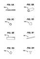
- FIGS. 5A-5Hillustrate several embodiments of markers for use with an implant according to the present invention
- FIG. 6Aillustrates a perspective view of another embodiment of a trial implant having several radio-lucent sphere markers positioned around and/or within the implant;
- FIG. 6Billustrates a top view of the implant of FIG. 6A
- FIG. 6Cillustrates two misaligned sphere markers
- FIG. 7Aillustrates a perspective view of yet another embodiment of a trial implant having several radio-lucent markers positioned around and/or within the implant;
- FIG. 7Billustrates a front view of the trial implant of FIG. 7A.
- FIG. 7Cillustrates a ring marker and a cross marker being misaligned with respect to each other.
- the present inventionprovides a trial implant and trial implant kit for assisting a physician in selecting an appropriately sized prosthesis.
- the trial implantis effective to indicate, on an x-ray image, the shape, size, and/or position of the implant with respect to an anatomical structure when the implant is positioned within or adjacent the anatomical structure.
- the implant 10generally includes a body 12 formed from a radio-lucent material, and at least one marker 14 associated with the body 12 and formed from a radio-opaque material.
- FIG. 1illustrates one example of a trial implant 10 having a disc-shaped body 12 adapted to be positioned between adjacent vertebral bodies.
- the bodyincludes superior and inferior surfaces 16 s , 16 i , posterior and anterior sides 18 p , 18 a , first and second lateral sides 20 a , 20 b , respectively, and a perimeter P (FIG. 2 A).
- the posterior side 18 p of the illustrated body 12is preferably substantially flat, while the anterior side 18 a and the first and second lateral sides 20 a , 20 b preferably form a curved convex portion of the perimeter P between opposite ends 18 p 1 , 18 p 2 of the flattened posterior side 18 p.
- the superior and inferior surfaces 16 s , 16 i of the body 12can have a variety of shapes, sizes, and/or features present on one of both of the surfaces 16 s , 16 i .
- one or both of the surfaces 16 s , 16 ican have a wedge-like shape (not shown) wherein one side (e.g., posterior) of the body 12 member has a height less than a height of the opposed side (e.g., anterior) of the body 12 .
- Other profilesinclude, for example, a supine shape, a converging portion, and a domed or convex-like profile.
- the trial implantcan be adapted to be used with either unprepared or prepared bony endplates of adjacent vertebrae.
- the trial implant 10further includes one or more markers that are effective to indicate, on an x-ray image, the size, shape, and/or position of the implant 10 with respect to adjacent bone structures.
- the markersare formed from a radio-opaque material and can have virtually any shape and size.
- FIG. 1illustrates one example of a trial implant 10 having several marker strips 14 that extend around the body 12 .
- the marker strips 14are formed from generally elongate strip-like members. Each strip 14 preferably has a width w sufficient to be detectable on an x-ray image.
- the marker strips 14are shown extending around the body 12 , the marker strips 14 can alternatively, or in addition, have varying lengths and can be disposed at distinct positions on or within the body.
- two marker strips 14could be positioned to form an x-like marking to indicate a particular reference point on the body 12 .
- the marker stripscan vary in shape and size.
- the position of the marker strips 14 on the body 12can also vary, but preferably the strips 14 are strategically positioned around and/or within the body 12 of the implant 10 to assist a physician in assessing the size, shape, and/or alignment of the implant 10 , via an x-ray image, with respect to bone structures surrounding an interstitial space.
- FIGS. 2A-2Cillustrate implant 10 having five marker strips disposed around the body 12 to essentially outline the shape of the body 12 .
- FIG. 2Aillustrates a superior view of the implant having marker strips 14 a and 14 b extending around the implant 10 between the first and second lateral sides 20 a , 20 b of the implant, and having marker strips 14 c and 14 d extending around the posterior and anterior sides 18 a , 18 p of the implant 10 .
- FIG. 2Billustrates a lateral side view of the implant having an additional marker strip 14 e that extends around the perimeter p of the implant 10 .
- FIG. 2Cillustrates an additional, anterior view of the implant 10 having marker strips 14 a - 14 e.
- FIG. 3illustrates an x-ray image of implant 10 having marker strips 14 a - 14 e .
- marker strips 14 c and 14 deach extend around the implant 10 to form a generally rectangular object on the x-ray image. The corners of the marker strips can be used as reference points.
- the marker strips 14 c and 14 dfurther intersect with marker strips 14 a and 14 b to form additional reference points (shown as white dots for reference purposes).
- four reference points 30 sare positioned on the superior surface 16 s of the implant, and four reference points 30 i are positioned on the inferior surface 16 i of the implant 10 .
- the implant 10also includes two references points 301 on each of the lateral sides 20 a , 20 b , and two references points 30 a on each of the anterior and posterior sides 18 a , 18 p.
- FIG. 4illustrates, for example, an implant 10 positioned between adjacent vertebrae 40 , 42 .
- the comers of marker strips 14 a and 14 bform reference points 32 a , 32 b , 32 c , and 32 d , which can be used to verify the alignment of the implant 10 with respect to the endplates of the adjacent vertebrae 40 , 42 .
- FIGS. 5A-5Hillustrate additional embodiments of markers suitable for use with a trial implant.
- FIG. 5Aillustrates a marker strip 14 a , which is essentially the same as the marker strip shown in the implant of FIGS. 1-4.
- FIG. 5Billustrates a cylinder marker 14 b , which is particularly useful in that an x-ray image of the cylinder marker 14 b will appear as a circle if the implant is properly aligned.
- FIG. 5Cillustrates a ring marker 14 c .
- the ring marker 14 cis preferably used as an alignment guide in combination with a marker having a different shape. In use, an x-ray image of the ring marker 14 c can be used to align another marker in the center of the ring 14 c .
- FIG. 5Aillustrates a marker strip 14 a , which is essentially the same as the marker strip shown in the implant of FIGS. 1-4.
- FIG. 5Billustrates a cylinder marker 14 b , which
- FIG. 5Dillustrates another embodiment of a marker 14 d having a spherical shape.
- the spherical marker 14 dcan be used in combination with other spherical markers 14 d such that an x-ray image of a properly aligned implant having two spheres 14 d positioned along an axis will display only a single sphere 14 d .
- FIG. 5Eillustrates a plate marker 14 e having a substantially flattened rectangular shape.
- the plate marker 14 eis particularly useful to indicate the angular relationship of the implant with respect to bone structures adjacent an interstitial space.
- the plate marker 14 eis preferably used in combination with a ring marker 14 c , cylinder marker 14 b , or with additional plate markers 14 e .
- FIG. 5Fillustrates a rod marker 14 f , which is also preferably used to indicate the angular relationship of the marker 14 f with respect to bone structures adjacent an interstitial space. When the implant is properly aligned, the rod marker 14 f will appear as a single point on an x-ray image.
- FIGS. 5G and 5Hillustrate additional embodiments of markers.
- FIG. 5Gillustrates a marker 14 g in the shape of a cross
- FIG. 5Hillustrates a T-shaped marker 14 h .
- the cross and T-shaped markers 14 g , 14 hare preferably used in combination with the ring 14 c , cylinder 14 b , or spherical markers 14 d , and will appear centered with respect to the other markers when properly aligned.
- Two T-shaped markers 14 hcan also be positioned along an axis and inverted with respect to each other such that an x-ray image of the markers 14 h , when properly aligned, will illustrate a cross or the letter “H,” depending on the position of the markers 14 h .
- the markers of the present inventioncan have virtually any configuration and can be used in combination with any number of markers having the same or a different configuration.
- pairs of markersare positioned along a predetermined axis of the implant.
- An x-ray image, taken along a particular axis,can then be used to verify the alignment of the implant. If the implant is properly aligned, the pair of markers positioned along the axis will appear as a single marker, or will be displayed in some configuration indicative of alignment of the implant.
- the pairs of markersare preferably positioned on opposed sides of the implant to provide greater accuracy in alignment of the implant.
- FIG. 6Aillustrates an exemplary embodiment of an implant 10 d having a body 12 d with several sphere-shaped markers 14 d positioned in pairs throughout the body 12 d along predetermined axes t 1-4 , V 1-4 .
- Axes v 1 , v 2 , V 3 , and V 4extend between the superior and inferior surfaces 16 s ′, 16 i ′, axes t 3 and t 4 extend between the posterior and anterior sides 18 p ′, 18 a ′, and axes t 1 and t 2 extend between the first and second lateral sides 20 a ′, 20 b ′.
- Two markersare positioned along each axis, as shown.
- each marker paircan be used to determine the proper alignment of the implant.
- FIG. 6Billustrates an x-ray image of a top view of the superior surface 16 s ' of the implant 10 d .
- the pairs of markers that extend along axes v 1 , v 2 , v 3 , and v 4are each shown as a single marker 14 d , thereby indicating that the implant is properly aligned.
- the pairs of markerswould each be displayed adjacent or offset from one another, as shown in FIG. 6 C.
- FIG. 7Aillustrates another embodiment of a trial implant 10 c having at least one pair of markers 14 c , 14 g positioned on opposed sides of the implant 10 c along an axis t 5 .
- one of the markers 14 cis in the shape of a ring
- the opposed marker 14 gis in the shape of a cross.
- FIG. 7Billustrates an x-ray image of the implant 10 c taken along axis 15 . The implant is properly aligned since the x-ray image illustrates the cross-shaped marker 14 g centered within the ring-shaped marker 14 c .
- FIG. 7Cillustrates an example of the image of markers that is obtained in an improperly aligned implant in which the cross-shaped marker 14 g is off-center with respect to the ring-shaped maker 14 c.
- the trial implant of the present inventioncan be provided as a system or kit containing several implantable trial implants.
- Each implantpreferably has a different shape and/or size, which is identical to, or similar to, a shape and size of an available prosthesis to be implanted.
- Each trial implantincludes a body formed from a radio-lucent material and having a size and shape adapted to fit within or adjacent to an anatomical structure, and at least one marker strip associated with the body and formed from a radio-opaque material.
- the marker stripsare configured to indicate, on an x-ray image, the size and alignment of the body with respect to the anatomical structure when the implantable trial prosthesis is positioned within or adjacent to an anatomical structure.
- the surgeoncan select an implant from among several implants provided in the kit, and position and x-ray the implant to determine the fit. In the event that the selected trial implant does not fit appropriately, the surgeon can then select another implant from the kit. This process is repeated until the surgeon has selected the appropriately sized implant for that particular patient.
- a trial implantcan be manufactured by strategically placing at least one marker strip formed from a radio-opaque material into a mold having a desired size and shape for a medical implant.
- the marker stripsare preferably positioned and configured to indicate, on an x-ray image, the size and shape of the medical implant.
- a radio-lucent materialcan then be injected into the mold to form a trial implant.
- the body 12is formed from a rigid, semi-rigid, or flexible radio-lucent material. More preferably, the body 12 is formed from materials such as polymers, ceramics, composite materials, and combinations thereof. Examples of suitable polymers include polyether sulfone, polycarbonate, and bioabsorbable polymers, and examples of suitable composites include carbon fiber reinforced polymers.
- the marker stripcan also be formed from a variety of radio-opaque materials including, for example, metals, polymers, filling salts, ceramics, and combinations thereof. Examples of suitable metals include titanium, stainless steel, tantalum, cobalt chromium, aluminum, and combinations thereof. A person having ordinary skill in the art will appreciate that the body can be formed from a radio-opaque material, and the marker strip can be formed from a radio-lucent material.
Landscapes
- Health & Medical Sciences (AREA)
- Transplantation (AREA)
- Orthopedic Medicine & Surgery (AREA)
- Heart & Thoracic Surgery (AREA)
- Cardiology (AREA)
- Oral & Maxillofacial Surgery (AREA)
- Engineering & Computer Science (AREA)
- Biomedical Technology (AREA)
- Physical Education & Sports Medicine (AREA)
- Vascular Medicine (AREA)
- Life Sciences & Earth Sciences (AREA)
- Animal Behavior & Ethology (AREA)
- General Health & Medical Sciences (AREA)
- Public Health (AREA)
- Veterinary Medicine (AREA)
- Prostheses (AREA)
Abstract
Description
Claims (30)
Priority Applications (7)
| Application Number | Priority Date | Filing Date | Title |
|---|---|---|---|
| US10/200,890US6723097B2 (en) | 2002-07-23 | 2002-07-23 | Surgical trial implant |
| AU2003204910AAU2003204910B2 (en) | 2002-07-23 | 2003-06-24 | Surgical trial implant |
| DE60331120TDE60331120D1 (en) | 2002-07-23 | 2003-07-01 | Surgical trial implant |
| AT03254180TATE456339T1 (en) | 2002-07-23 | 2003-07-01 | SURGICAL TRIAL IMPLANT |
| EP03254180AEP1384455B1 (en) | 2002-07-23 | 2003-07-01 | Surgical trial implant |
| JP2003277733AJP2004130097A (en) | 2002-07-23 | 2003-07-22 | Surgical trial implant |
| CA002435862ACA2435862A1 (en) | 2002-07-23 | 2003-07-23 | Surgical trial implant |
Applications Claiming Priority (1)
| Application Number | Priority Date | Filing Date | Title |
|---|---|---|---|
| US10/200,890US6723097B2 (en) | 2002-07-23 | 2002-07-23 | Surgical trial implant |
Publications (2)
| Publication Number | Publication Date |
|---|---|
| US20040019356A1 US20040019356A1 (en) | 2004-01-29 |
| US6723097B2true US6723097B2 (en) | 2004-04-20 |
Family
ID=30000077
Family Applications (1)
| Application Number | Title | Priority Date | Filing Date |
|---|---|---|---|
| US10/200,890Expired - Fee RelatedUS6723097B2 (en) | 2002-07-23 | 2002-07-23 | Surgical trial implant |
Country Status (7)
| Country | Link |
|---|---|
| US (1) | US6723097B2 (en) |
| EP (1) | EP1384455B1 (en) |
| JP (1) | JP2004130097A (en) |
| AT (1) | ATE456339T1 (en) |
| AU (1) | AU2003204910B2 (en) |
| CA (1) | CA2435862A1 (en) |
| DE (1) | DE60331120D1 (en) |
Cited By (99)
| Publication number | Priority date | Publication date | Assignee | Title |
|---|---|---|---|---|
| US20050020913A1 (en)* | 2003-04-10 | 2005-01-27 | Christian Georg | Method and x-ray system for detecting position changes of a medical implant |
| US20050033438A1 (en)* | 2003-07-08 | 2005-02-10 | Robert Schultz | Intervertebral implant |
| US20050043803A1 (en)* | 2003-08-22 | 2005-02-24 | Robert Schultz | Intervertebral implant |
| US20050060036A1 (en)* | 2003-05-21 | 2005-03-17 | Robert Schultz | Spinal column implant |
| US20050080487A1 (en)* | 2003-10-08 | 2005-04-14 | Robert Schultz | Intervertebral implant |
| US20050107888A1 (en)* | 2001-06-14 | 2005-05-19 | Amedica Corporation | Metal-ceramic composite articulation |
| US20050143824A1 (en)* | 2003-05-06 | 2005-06-30 | Marc Richelsoph | Artificial intervertebral disc |
| US20050177238A1 (en)* | 2001-05-01 | 2005-08-11 | Khandkar Ashok C. | Radiolucent bone graft |
| US20050240273A1 (en)* | 2002-12-17 | 2005-10-27 | Khandkar Ashock C | Total disc implant |
| US20050251262A1 (en)* | 2002-09-19 | 2005-11-10 | Spinalmotion, Inc. | Intervertebral prosthesis |
| US20060009541A1 (en)* | 2004-07-09 | 2006-01-12 | Yih-Fang Chen | Saturant for friction material containing friction modifying layer |
| US20060020341A1 (en)* | 2004-06-16 | 2006-01-26 | Susanne Schneid | Intervertebral implant |
| US20060030857A1 (en)* | 2004-08-06 | 2006-02-09 | Spinalmotion, Inc. | Methods and apparatus for intervertebral disc prosthesis insertion |
| US20060052875A1 (en)* | 2001-05-01 | 2006-03-09 | Amedica Corporation | Knee prosthesis with ceramic tibial component |
| US20060167550A1 (en)* | 2002-10-08 | 2006-07-27 | Robert Snell | High precision manufacture of polyurethane products such as spinal disc implants having a gradual modulus variation |
| US20060229723A1 (en)* | 2005-04-08 | 2006-10-12 | Sdgi Holdings, Inc. | Intervertebral fusion device and method |
| US20060265072A1 (en)* | 2003-05-06 | 2006-11-23 | Marc Richelsoph | Artificial intervertebral disc |
| US7189235B2 (en) | 1999-10-20 | 2007-03-13 | Anulex Technologies, Inc. | Spinal disc annulus reconstruction method and spinal disc annulus stent |
| US20070093825A1 (en)* | 2005-09-28 | 2007-04-26 | Nuvasive Inc. | Methods and apparatus for treating spinal stenosis |
| US20070191952A1 (en)* | 2006-02-16 | 2007-08-16 | Amedica Corporation | Spinal implant with elliptical articulatory interface |
| US20070198093A1 (en)* | 2006-02-17 | 2007-08-23 | Amedica Corporation | Spinal implant with offset keels |
| US20070270851A1 (en)* | 2006-04-28 | 2007-11-22 | David Erickson | Radiolucent bone plate systems and methods of use |
| US20070276492A1 (en)* | 2006-05-09 | 2007-11-29 | Ranier Limited | Artificial spinal disc implant |
| US20080125864A1 (en)* | 2006-04-12 | 2008-05-29 | Spinalmotion, Inc. | Posterior Spinal Device and Method |
| US20080133011A1 (en)* | 2003-05-27 | 2008-06-05 | Spinalmotion, Inc. | Prosthetic Disc for Intervertebral Insertion |
| US20080140204A1 (en)* | 2006-12-07 | 2008-06-12 | Warsaw Orthopedic, Inc. | Vertebral Implant Systems and Methods of Use |
| US20080221689A1 (en)* | 2007-03-10 | 2008-09-11 | Christopher Chaput | Artificial disc with unique articulating geometry and associated methods |
| US20080243252A1 (en)* | 2007-04-02 | 2008-10-02 | Centra-Fuse, Inc. | Spinal implant system |
| US20080269898A1 (en)* | 2007-04-25 | 2008-10-30 | Warsaw Orthopedic, Inc. | Device and method for image-based device performance measurement |
| US20080306598A1 (en)* | 2007-04-02 | 2008-12-11 | Eric Hansen | Spinal implant with biologic sponge |
| US20090076614A1 (en)* | 2007-09-17 | 2009-03-19 | Spinalmotion, Inc. | Intervertebral Prosthetic Disc with Shock Absorption Core |
| US7549995B2 (en) | 2003-07-08 | 2009-06-23 | Aesculap Ag | Surgical instrument for handling an implant |
| US20090216330A1 (en)* | 2004-09-23 | 2009-08-27 | Christophe Geisert | System and method for an intervertebral implant |
| US20090270988A1 (en)* | 2008-04-24 | 2009-10-29 | Ranier Limited | Artificial spinal disc implant |
| US7615076B2 (en) | 1999-10-20 | 2009-11-10 | Anulex Technologies, Inc. | Method and apparatus for the treatment of the intervertebral disc annulus |
| US7637913B2 (en)* | 2003-01-31 | 2009-12-29 | Spinalmotion, Inc. | Spinal midline indicator |
| US7695521B2 (en) | 2001-05-01 | 2010-04-13 | Amedica Corporation | Hip prosthesis with monoblock ceramic acetabular cup |
| US20100145389A1 (en)* | 2006-09-25 | 2010-06-10 | Stryker Spine | Rod inserter and rod with reduced diameter end |
| US7753941B2 (en) | 2000-04-04 | 2010-07-13 | Anulex Technologies, Inc. | Devices and methods for annular repair of intervertebral discs |
| US7828850B2 (en) | 1999-10-20 | 2010-11-09 | Anulex Technologies, Inc. | Methods and devices for spinal disc annulus reconstruction and repair |
| US7832409B2 (en) | 2003-05-06 | 2010-11-16 | Aesculap Implant Systems, Llc | Method of inserting an artificial intervertebral disc |
| US7922768B2 (en) | 1999-10-20 | 2011-04-12 | Anulex Technologies, Inc. | Spinal disc annulus reconstruction method and deformable spinal disc annulus stent |
| US20110087293A1 (en)* | 2009-10-14 | 2011-04-14 | Ebi, Llc | Deformable Device For Minimally Invasive Fixation |
| US20110098746A1 (en)* | 2005-12-06 | 2011-04-28 | Nuvasive, Inc. | Methods and Apparatus For Treating Spinal Stenosis |
| US7935147B2 (en) | 1999-10-20 | 2011-05-03 | Anulex Technologies, Inc. | Method and apparatus for enhanced delivery of treatment device to the intervertebral disc annulus |
| US7951201B2 (en) | 1999-10-20 | 2011-05-31 | Anulex Technologies, Inc. | Method and apparatus for the treatment of the intervertebral disc annulus |
| US8002834B2 (en) | 2004-07-30 | 2011-08-23 | Spinalmotion, Inc. | Intervertebral prosthetic disc with metallic core |
| US8038699B2 (en) | 2006-09-26 | 2011-10-18 | Ebi, Llc | Percutaneous instrument assembly |
| US8083797B2 (en) | 2005-02-04 | 2011-12-27 | Spinalmotion, Inc. | Intervertebral prosthetic disc with shock absorption |
| US8128698B2 (en) | 1999-10-20 | 2012-03-06 | Anulex Technologies, Inc. | Method and apparatus for the treatment of the intervertebral disc annulus |
| US8162952B2 (en) | 2006-09-26 | 2012-04-24 | Ebi, Llc | Percutaneous instrument assembly |
| US8163022B2 (en) | 2008-10-14 | 2012-04-24 | Anulex Technologies, Inc. | Method and apparatus for the treatment of the intervertebral disc annulus |
| US8206449B2 (en) | 2008-07-17 | 2012-06-26 | Spinalmotion, Inc. | Artificial intervertebral disc placement system |
| US8292923B1 (en) | 2008-10-13 | 2012-10-23 | Nuvasive, Inc. | Systems and methods for treating spinal stenosis |
| WO2012170045A1 (en)* | 2011-06-10 | 2012-12-13 | Cibor, Inc. | Radiolucent surgical instruments |
| US8353964B2 (en) | 2010-11-04 | 2013-01-15 | Carpenter Clyde T | Anatomic total disc replacement |
| US20130103160A1 (en)* | 2010-04-22 | 2013-04-25 | Depuy (Ireland) | Composite trial prosthesis |
| US8460319B2 (en) | 2010-01-11 | 2013-06-11 | Anulex Technologies, Inc. | Intervertebral disc annulus repair system and method |
| US8506631B2 (en) | 2007-08-09 | 2013-08-13 | Spinalmotion, Inc. | Customized intervertebral prosthetic disc with shock absorption |
| US8556977B2 (en) | 1999-10-20 | 2013-10-15 | Anulex Technologies, Inc. | Tissue anchoring system and method |
| US8574301B2 (en)* | 2004-03-29 | 2013-11-05 | Nuvasive, Inc. | Systems and methods for spinal fusion |
| US8611504B2 (en)* | 2011-08-19 | 2013-12-17 | Orthogrid Systems, Llc | Alignment plate apparatus and method of use |
| US8685035B2 (en) | 2003-01-31 | 2014-04-01 | Spinalmotion, Inc. | Intervertebral prosthesis placement instrument |
| US8758441B2 (en) | 2007-10-22 | 2014-06-24 | Spinalmotion, Inc. | Vertebral body replacement and method for spanning a space formed upon removal of a vertebral body |
| US8764833B2 (en) | 2008-03-11 | 2014-07-01 | Spinalmotion, Inc. | Artificial intervertebral disc with lower height |
| US8834526B2 (en) | 2006-08-09 | 2014-09-16 | Rolando Garcia | Methods and apparatus for treating spinal stenosis |
| US8845730B2 (en) | 2008-07-18 | 2014-09-30 | Simplify Medical, Inc. | Posterior prosthetic intervertebral disc |
| USD720071S1 (en)* | 2002-10-04 | 2014-12-23 | Bruce H. Robie | Vertebral implant |
| USD720456S1 (en)* | 2012-07-26 | 2014-12-30 | Paragon 28, Inc. | Lapidus bone wedge |
| USD720457S1 (en)* | 2012-07-26 | 2014-12-30 | Paragon 28, Inc. | Calcaneo-cuboid bone wedge |
| US8968412B2 (en) | 2011-06-30 | 2015-03-03 | Depuy (Ireland) | Trialing system for a knee prosthesis and method of use |
| US9011544B2 (en) | 2008-05-05 | 2015-04-21 | Simplify Medical, Inc. | Polyaryletherketone artificial intervertebral disc |
| US9034038B2 (en) | 2008-04-11 | 2015-05-19 | Spinalmotion, Inc. | Motion limiting insert for an artificial intervertebral disc |
| US9084688B2 (en) | 2009-05-19 | 2015-07-21 | DePuy Synthes Products, Inc. | Dynamic trial implants |
| US9168152B2 (en) | 2008-02-29 | 2015-10-27 | Nuvasive, Inc. | Implants and methods for spinal fusion |
| US9186261B2 (en) | 2007-03-07 | 2015-11-17 | Nuvasive, Inc. | System and methods for spinal fusion |
| US9198765B1 (en) | 2011-10-31 | 2015-12-01 | Nuvasive, Inc. | Expandable spinal fusion implants and related methods |
| US9220603B2 (en) | 2008-07-02 | 2015-12-29 | Simplify Medical, Inc. | Limited motion prosthetic intervertebral disc |
| US9289310B2 (en) | 2007-03-10 | 2016-03-22 | Spinesmith Partners, L.P. | Artificial disc with post and modular collar |
| USD754346S1 (en) | 2009-03-02 | 2016-04-19 | Nuvasive, Inc. | Spinal fusion implant |
| US9655741B2 (en) | 2003-05-27 | 2017-05-23 | Simplify Medical Pty Ltd | Prosthetic disc for intervertebral insertion |
| US9693882B2 (en) | 2014-06-03 | 2017-07-04 | DePuy Synthes Products, Inc. | Optical trial device |
| US20170202679A1 (en)* | 2007-03-29 | 2017-07-20 | Life Spine, Inc. | Radially expandable spinal interbody device and implantation tool |
| US9737294B2 (en) | 2013-01-28 | 2017-08-22 | Cartiva, Inc. | Method and system for orthopedic repair |
| USRE46647E1 (en) | 2001-05-03 | 2017-12-26 | DePuy Synthes Products, Inc. | Intervertebral implant for transforaminal posterior lumbar interbody fusion procedure |
| US9861491B2 (en) | 2014-04-30 | 2018-01-09 | Depuy Ireland Unlimited Company | Tibial trial system for a knee prosthesis |
| USD813394S1 (en)* | 2017-01-17 | 2018-03-20 | Paragon 28, Inc. | Wedge insert |
| USD814037S1 (en)* | 2017-01-17 | 2018-03-27 | Paragon 28, Inc. | Spacer wedge |
| USD814634S1 (en)* | 2017-01-17 | 2018-04-03 | Paragon 28, Inc. | Wedge insert |
| US10098707B2 (en) | 2015-08-17 | 2018-10-16 | Orthogrid Systems Inc. | Surgical positioning system, apparatus and method of use |
| US10179012B2 (en) | 2013-01-28 | 2019-01-15 | Cartiva, Inc. | Systems and methods for orthopedic repair |
| US10195056B2 (en) | 2015-10-19 | 2019-02-05 | Depuy Ireland Unlimited Company | Method for preparing a patient's tibia to receive an implant |
| USD849944S1 (en)* | 2015-09-04 | 2019-05-28 | Paragon 28, Inc. | Bone wedge implant |
| US10335288B2 (en) | 2007-03-10 | 2019-07-02 | Spinesmith Partners, L.P. | Surgical implant secured by pegs and associated methods |
| US20190298545A1 (en)* | 2018-03-30 | 2019-10-03 | Warsaw Orthopedic, Inc. | Radiolucent trial |
| US10537447B2 (en) | 2018-03-30 | 2020-01-21 | Warsaw Orthopedic, Inc. | Radiolucent trial |
| US10537445B2 (en) | 2015-10-19 | 2020-01-21 | Depuy Ireland Unlimited Company | Surgical instruments for preparing a patient's tibia to receive an implant |
| US11166825B1 (en) | 2020-07-01 | 2021-11-09 | Warsaw Orthopedic, Inc. | Spinal implant |
| US11298241B2 (en) | 2007-03-29 | 2022-04-12 | Life Spine, Inc. | Radially expandable spinal interbody device and implantation tool |
Families Citing this family (28)
| Publication number | Priority date | Publication date | Assignee | Title |
|---|---|---|---|---|
| US6402750B1 (en)* | 2000-04-04 | 2002-06-11 | Spinlabs, Llc | Devices and methods for the treatment of spinal disorders |
| WO2004084742A1 (en)* | 2003-03-24 | 2004-10-07 | Theken Surgical Llc | Spinal implant adjustment device |
| US7485145B2 (en)* | 2004-02-23 | 2009-02-03 | Alphatec Spine, Incorporated | Artificial intervertebral disc assembly |
| US7544208B1 (en) | 2004-05-03 | 2009-06-09 | Theken Spine, Llc | Adjustable corpectomy apparatus |
| KR20120102806A (en)* | 2004-09-23 | 2012-09-18 | 스파인 소루션 아이앤씨 | System and method for an intervertebral implant |
| CA2618771C (en)* | 2005-08-10 | 2015-03-24 | Synthes (U.S.A.) | Porous implant |
| AU2006282828B2 (en) | 2005-08-23 | 2013-01-31 | Smith & Nephew, Inc | Telemetric orthopaedic implant |
| US9849216B2 (en) | 2006-03-03 | 2017-12-26 | Smith & Nephew, Inc. | Systems and methods for delivering a medicament |
| US8333805B2 (en) | 2006-03-20 | 2012-12-18 | Howmedica Osteonics Corp. | Composite joint implant |
| US20100191333A1 (en)* | 2007-06-08 | 2010-07-29 | Morrison Iii Thomas J | Load-bearing spinal interbody device |
| ES2651269T3 (en) | 2007-06-20 | 2018-01-25 | Medical Components, Inc. | Venous reservoir with molded indications and / or radiopacas |
| WO2009012385A1 (en) | 2007-07-19 | 2009-01-22 | Medical Components, Inc. | Venous access port assembly with x-ray discernable indicia |
| US9610432B2 (en) | 2007-07-19 | 2017-04-04 | Innovative Medical Devices, Llc | Venous access port assembly with X-ray discernable indicia |
| WO2009132302A1 (en) | 2008-04-25 | 2009-10-29 | Pioneer Surgical Technology, Inc. | Bone plate system |
| EP2328519B1 (en)* | 2008-06-05 | 2014-12-31 | Alphatec Spine, Inc. | Modular anterior locking interbody cage |
| BRPI0920250A2 (en) | 2008-10-15 | 2016-11-22 | Smith & Nephew Inc | composite internal fasteners |
| US9028553B2 (en) | 2009-11-05 | 2015-05-12 | DePuy Synthes Products, Inc. | Self-pivoting spinal implant and associated instrumentation |
| GB201108185D0 (en)* | 2011-05-17 | 2011-06-29 | Depuy Spine Sarl | Medical implant, method for manufacturing a medical implant and curable mixture |
| WO2013036707A1 (en) | 2011-09-09 | 2013-03-14 | Spine Wave, Inc. | Lateral approach expandable spinal implant and method |
| US9198769B2 (en) | 2011-12-23 | 2015-12-01 | Pioneer Surgical Technology, Inc. | Bone anchor assembly, bone plate system, and method |
| US10022245B2 (en) | 2012-12-17 | 2018-07-17 | DePuy Synthes Products, Inc. | Polyaxial articulating instrument |
| US10863976B2 (en)* | 2013-10-07 | 2020-12-15 | Warsaw Orthopedic, Inc. | Spinal implant system and method for lumbar and lumbosacral fusion |
| US9918851B2 (en) | 2014-10-22 | 2018-03-20 | Stryker European Holdings I, Llc | Spinal fusion implant |
| CA3025434A1 (en)* | 2016-06-03 | 2017-12-07 | DePuy Synthes Products, Inc. | Surgical templates with radio-opaque markings |
| US10624760B2 (en) | 2017-05-22 | 2020-04-21 | Warsaw Orthopedic, Inc. | Spinal implant system and method |
| US10966843B2 (en) | 2017-07-18 | 2021-04-06 | DePuy Synthes Products, Inc. | Implant inserters and related methods |
| US11045331B2 (en) | 2017-08-14 | 2021-06-29 | DePuy Synthes Products, Inc. | Intervertebral implant inserters and related methods |
| US11998457B2 (en)* | 2020-05-05 | 2024-06-04 | Corelink, Llc | Implant trial with radiographically visible indicium |
Citations (18)
| Publication number | Priority date | Publication date | Assignee | Title |
|---|---|---|---|---|
| US4795463A (en)* | 1984-10-03 | 1989-01-03 | Baylor College Of Medicine | Labeled breast prosthesis and methods for detecting and predicting rupture of the prosthesis |
| US4834757A (en) | 1987-01-22 | 1989-05-30 | Brantigan John W | Prosthetic implant |
| US4985019A (en)* | 1988-03-11 | 1991-01-15 | Michelson Gary K | X-ray marker |
| US5045080A (en) | 1986-12-22 | 1991-09-03 | Johnson & Johnson Medical, Inc. | Surgical fabric with printed X-ray marker |
| US5071437A (en)* | 1989-02-15 | 1991-12-10 | Acromed Corporation | Artificial disc |
| US5133342A (en) | 1990-12-26 | 1992-07-28 | Seaton James I | Lever to align bones |
| US5361766A (en) | 1993-02-17 | 1994-11-08 | David Nichols | Quick release bone probe and x-ray marker |
| US5383233A (en) | 1993-05-07 | 1995-01-17 | Beekly Corporation | Method for identifying artifactual radiographic images caused by epithelial protuberances |
| WO1996000539A1 (en) | 1994-06-30 | 1996-01-11 | Howmedica, Inc. | Modular femoral trial hip replacement system |
| US5676146A (en)* | 1996-09-13 | 1997-10-14 | Osteotech, Inc. | Surgical implant containing a resorbable radiopaque marker and method of locating such within a body |
| US6041094A (en) | 1993-05-07 | 2000-03-21 | Russell; Donald G. | Intermediate density marker and a method using such a marker for radiographic examination |
| US6093201A (en)* | 1999-01-19 | 2000-07-25 | Ethicon, Inc. | Biocompatible absorbable polymer plating system for tissue fixation |
| US6113639A (en) | 1999-03-23 | 2000-09-05 | Raymedica, Inc. | Trial implant and trial implant kit for evaluating an intradiscal space |
| US6132465A (en)* | 1998-06-04 | 2000-10-17 | Raymedica, Inc. | Tapered prosthetic spinal disc nucleus |
| US6146422A (en) | 1999-01-25 | 2000-11-14 | Lawson; Kevin Jon | Prosthetic nucleus replacement for surgical reconstruction of intervertebral discs and treatment method |
| US6200258B1 (en) | 1999-08-10 | 2001-03-13 | Syntheon, Llc | Radioactive therapeutic seed having selective marker configuration |
| US6264695B1 (en)* | 1999-09-30 | 2001-07-24 | Replication Medical, Inc. | Spinal nucleus implant |
| WO2001070144A1 (en) | 2000-03-22 | 2001-09-27 | Scolio Gmbh | Cage-type intervertebral implant |
Family Cites Families (1)
| Publication number | Priority date | Publication date | Assignee | Title |
|---|---|---|---|---|
| US5812786A (en)* | 1995-06-21 | 1998-09-22 | Bell Atlantic Network Services, Inc. | Variable rate and variable mode transmission system |
- 2002
- 2002-07-23USUS10/200,890patent/US6723097B2/ennot_activeExpired - Fee Related
- 2003
- 2003-06-24AUAU2003204910Apatent/AU2003204910B2/ennot_activeCeased
- 2003-07-01DEDE60331120Tpatent/DE60331120D1/ennot_activeExpired - Lifetime
- 2003-07-01EPEP03254180Apatent/EP1384455B1/ennot_activeExpired - Lifetime
- 2003-07-01ATAT03254180Tpatent/ATE456339T1/ennot_activeIP Right Cessation
- 2003-07-22JPJP2003277733Apatent/JP2004130097A/enactivePending
- 2003-07-23CACA002435862Apatent/CA2435862A1/ennot_activeAbandoned
Patent Citations (19)
| Publication number | Priority date | Publication date | Assignee | Title |
|---|---|---|---|---|
| US4795463A (en)* | 1984-10-03 | 1989-01-03 | Baylor College Of Medicine | Labeled breast prosthesis and methods for detecting and predicting rupture of the prosthesis |
| US5045080A (en) | 1986-12-22 | 1991-09-03 | Johnson & Johnson Medical, Inc. | Surgical fabric with printed X-ray marker |
| US4834757A (en) | 1987-01-22 | 1989-05-30 | Brantigan John W | Prosthetic implant |
| US4985019A (en)* | 1988-03-11 | 1991-01-15 | Michelson Gary K | X-ray marker |
| US5071437A (en)* | 1989-02-15 | 1991-12-10 | Acromed Corporation | Artificial disc |
| US5133342A (en) | 1990-12-26 | 1992-07-28 | Seaton James I | Lever to align bones |
| US5361766A (en) | 1993-02-17 | 1994-11-08 | David Nichols | Quick release bone probe and x-ray marker |
| US6041094A (en) | 1993-05-07 | 2000-03-21 | Russell; Donald G. | Intermediate density marker and a method using such a marker for radiographic examination |
| US5383233A (en) | 1993-05-07 | 1995-01-17 | Beekly Corporation | Method for identifying artifactual radiographic images caused by epithelial protuberances |
| WO1996000539A1 (en) | 1994-06-30 | 1996-01-11 | Howmedica, Inc. | Modular femoral trial hip replacement system |
| US5676146A (en)* | 1996-09-13 | 1997-10-14 | Osteotech, Inc. | Surgical implant containing a resorbable radiopaque marker and method of locating such within a body |
| US5676146B1 (en)* | 1996-09-13 | 2000-04-18 | Osteotech Inc | Surgical implant containing a resorbable radiopaque marker and method of locating such within a body |
| US6132465A (en)* | 1998-06-04 | 2000-10-17 | Raymedica, Inc. | Tapered prosthetic spinal disc nucleus |
| US6093201A (en)* | 1999-01-19 | 2000-07-25 | Ethicon, Inc. | Biocompatible absorbable polymer plating system for tissue fixation |
| US6146422A (en) | 1999-01-25 | 2000-11-14 | Lawson; Kevin Jon | Prosthetic nucleus replacement for surgical reconstruction of intervertebral discs and treatment method |
| US6113639A (en) | 1999-03-23 | 2000-09-05 | Raymedica, Inc. | Trial implant and trial implant kit for evaluating an intradiscal space |
| US6200258B1 (en) | 1999-08-10 | 2001-03-13 | Syntheon, Llc | Radioactive therapeutic seed having selective marker configuration |
| US6264695B1 (en)* | 1999-09-30 | 2001-07-24 | Replication Medical, Inc. | Spinal nucleus implant |
| WO2001070144A1 (en) | 2000-03-22 | 2001-09-27 | Scolio Gmbh | Cage-type intervertebral implant |
Cited By (249)
| Publication number | Priority date | Publication date | Assignee | Title |
|---|---|---|---|---|
| US7993405B2 (en) | 1999-10-20 | 2011-08-09 | Anulex Technologies, Inc. | Spinal disc annulus repair system and methods |
| US8088165B2 (en) | 1999-10-20 | 2012-01-03 | Anulex Technologies, Inc. | Spinal disc annulus reconstruction method and deformable spinal disc annulus stent |
| US7749273B2 (en) | 1999-10-20 | 2010-07-06 | Anulex Technologies, Inc. | Method and apparatus for the treatment of the intervertebral disc annulus |
| US7951201B2 (en) | 1999-10-20 | 2011-05-31 | Anulex Technologies, Inc. | Method and apparatus for the treatment of the intervertebral disc annulus |
| US7985257B2 (en) | 1999-10-20 | 2011-07-26 | Anulex Technologies, Inc. | Methods and devices for spinal disc annulus reconstruction and repair |
| US9675347B2 (en) | 1999-10-20 | 2017-06-13 | Krt Investors, Inc. | Apparatus for the treatment of tissue |
| US7922768B2 (en) | 1999-10-20 | 2011-04-12 | Anulex Technologies, Inc. | Spinal disc annulus reconstruction method and deformable spinal disc annulus stent |
| US9095442B2 (en) | 1999-10-20 | 2015-08-04 | Krt Investors, Inc. | Method and apparatus for the treatment of the intervertebral disc annulus |
| US7670379B2 (en) | 1999-10-20 | 2010-03-02 | Anulex Technologies, Inc. | Spinal disc annulus reconstruction method |
| US7935147B2 (en) | 1999-10-20 | 2011-05-03 | Anulex Technologies, Inc. | Method and apparatus for enhanced delivery of treatment device to the intervertebral disc annulus |
| US7963992B2 (en) | 1999-10-20 | 2011-06-21 | Anulex Technologies, Inc. | Method and apparatus for the treatment of the intervertebral disc annulus |
| US8034112B2 (en) | 1999-10-20 | 2011-10-11 | Anulex Technologies, Inc. | Spinal disc annulus reconstruction method and spinal disc annulus stent |
| US7189235B2 (en) | 1999-10-20 | 2007-03-13 | Anulex Technologies, Inc. | Spinal disc annulus reconstruction method and spinal disc annulus stent |
| US7828850B2 (en) | 1999-10-20 | 2010-11-09 | Anulex Technologies, Inc. | Methods and devices for spinal disc annulus reconstruction and repair |
| US7615076B2 (en) | 1999-10-20 | 2009-11-10 | Anulex Technologies, Inc. | Method and apparatus for the treatment of the intervertebral disc annulus |
| US8048160B2 (en) | 1999-10-20 | 2011-11-01 | Anulex Technologies, Inc. | Intervertebral disc annulus stent |
| US8632590B2 (en) | 1999-10-20 | 2014-01-21 | Anulex Technologies, Inc. | Apparatus and methods for the treatment of the intervertebral disc |
| US7909879B2 (en) | 1999-10-20 | 2011-03-22 | Anulex Technologies, Inc. | Intervertebral disc annulus stent |
| US8556977B2 (en) | 1999-10-20 | 2013-10-15 | Anulex Technologies, Inc. | Tissue anchoring system and method |
| US9114025B2 (en) | 1999-10-20 | 2015-08-25 | Krt Investors, Inc. | Methods and devices for spinal disc annulus reconstruction and repair |
| US8128698B2 (en) | 1999-10-20 | 2012-03-06 | Anulex Technologies, Inc. | Method and apparatus for the treatment of the intervertebral disc annulus |
| US7905923B2 (en) | 2000-04-04 | 2011-03-15 | Anulex Technologies, Inc. | Devices and methods for annular repair of intervertebral discs |
| US7753941B2 (en) | 2000-04-04 | 2010-07-13 | Anulex Technologies, Inc. | Devices and methods for annular repair of intervertebral discs |
| US7776085B2 (en) | 2001-05-01 | 2010-08-17 | Amedica Corporation | Knee prosthesis with ceramic tibial component |
| US20060052875A1 (en)* | 2001-05-01 | 2006-03-09 | Amedica Corporation | Knee prosthesis with ceramic tibial component |
| US20050177238A1 (en)* | 2001-05-01 | 2005-08-11 | Khandkar Ashok C. | Radiolucent bone graft |
| US7695521B2 (en) | 2001-05-01 | 2010-04-13 | Amedica Corporation | Hip prosthesis with monoblock ceramic acetabular cup |
| USRE46647E1 (en) | 2001-05-03 | 2017-12-26 | DePuy Synthes Products, Inc. | Intervertebral implant for transforaminal posterior lumbar interbody fusion procedure |
| US7780738B2 (en) | 2001-06-14 | 2010-08-24 | Amedica Corporation | Polymer-ceramic articulation |
| US20050107888A1 (en)* | 2001-06-14 | 2005-05-19 | Amedica Corporation | Metal-ceramic composite articulation |
| US20080294259A1 (en)* | 2002-09-16 | 2008-11-27 | Spinalmotion, Inc. | Intervertebral prosthesis |
| US8262732B2 (en) | 2002-09-19 | 2012-09-11 | Spinalmotion, Inc. | Intervertebral prosthesis |
| US10166113B2 (en) | 2002-09-19 | 2019-01-01 | Simplify Medical Pty Ltd | Intervertebral prosthesis |
| US20070061011A1 (en)* | 2002-09-19 | 2007-03-15 | Spinalmotion, Inc. | Intervertebral Prosthesis |
| US20100179419A1 (en)* | 2002-09-19 | 2010-07-15 | Spinalmotion, Inc. | Intervertebral Prosthesis |
| US7731754B2 (en) | 2002-09-19 | 2010-06-08 | Spinalmotion, Inc. | Intervertebral prosthesis |
| US20080228277A1 (en)* | 2002-09-19 | 2008-09-18 | Spinalmotion, Inc. | Intervertebral prosthesis |
| US20050251262A1 (en)* | 2002-09-19 | 2005-11-10 | Spinalmotion, Inc. | Intervertebral prosthesis |
| US10517738B2 (en) | 2002-09-19 | 2019-12-31 | Simplify Medical Pty Ltd | Intervertebral prothesis |
| US11285013B2 (en) | 2002-09-19 | 2022-03-29 | Simplify Medical Pty Ltd | Intervertebral prosthesis |
| US9839525B2 (en) | 2002-09-19 | 2017-12-12 | Simplify Medical Pty Ltd | Intervertebral prosthesis |
| US10413420B2 (en) | 2002-09-19 | 2019-09-17 | Simplify Medical Pty Ltd | Intervertebral prosthesis |
| US7531001B2 (en) | 2002-09-19 | 2009-05-12 | Spinalmotion, Inc. | Intervertebral prosthesis |
| US20060293754A1 (en)* | 2002-09-19 | 2006-12-28 | Spinalmotion, Inc. | Intervertebral Prosthesis |
| US11707360B2 (en) | 2002-09-19 | 2023-07-25 | Simplify Medical Pty Ltd | Intervertebral prosthesis |
| US11344427B2 (en) | 2002-09-19 | 2022-05-31 | Simplify Medical Pty Ltd | Intervertebral prosthesis |
| USD720071S1 (en)* | 2002-10-04 | 2014-12-23 | Bruce H. Robie | Vertebral implant |
| US20060167550A1 (en)* | 2002-10-08 | 2006-07-27 | Robert Snell | High precision manufacture of polyurethane products such as spinal disc implants having a gradual modulus variation |
| US8882837B2 (en) | 2002-10-08 | 2014-11-11 | Ranier Limited | High precision manufacture of polyurethane products such as spinal disc implants having gradual modulus variation |
| US20070043443A1 (en)* | 2002-10-08 | 2007-02-22 | Ranier Technology Ltd. | High precision manufacture of polyurethane products such as spinal disc implants having gradual modulus variation |
| US8353960B2 (en) | 2002-10-08 | 2013-01-15 | Ranier Limited | High precision manufacture of polyurethane products such as spinal disc implants having a gradual modulus variation |
| US20070050037A1 (en)* | 2002-10-08 | 2007-03-01 | Ranier Technology Ltd. | High precision manufacture of polyurethane products such as spinal disc implants having gradual modulus variation |
| US20070050038A1 (en)* | 2002-10-08 | 2007-03-01 | Ranier Technology Ltd. | High precision manufacture of polyurethane products such as spinal disc implants having gradual modulus variation |
| US20050240273A1 (en)* | 2002-12-17 | 2005-10-27 | Khandkar Ashock C | Total disc implant |
| US7758646B2 (en) | 2002-12-17 | 2010-07-20 | Amedica Corporation | Total disc implant |
| US20080033563A1 (en)* | 2002-12-17 | 2008-02-07 | Amedica Corporation | Total disc implant |
| US7771481B2 (en) | 2002-12-17 | 2010-08-10 | Amedica Corporation | Total disc implant |
| US9402745B2 (en) | 2003-01-31 | 2016-08-02 | Simplify Medical, Inc. | Intervertebral prosthesis placement instrument |
| US7637913B2 (en)* | 2003-01-31 | 2009-12-29 | Spinalmotion, Inc. | Spinal midline indicator |
| US10105131B2 (en) | 2003-01-31 | 2018-10-23 | Simplify Medical Pty Ltd | Intervertebral prosthesis placement instrument |
| US8090428B2 (en) | 2003-01-31 | 2012-01-03 | Spinalmotion, Inc. | Spinal midline indicator |
| US8685035B2 (en) | 2003-01-31 | 2014-04-01 | Spinalmotion, Inc. | Intervertebral prosthesis placement instrument |
| US7660624B2 (en)* | 2003-04-10 | 2010-02-09 | Siemens Aktiengesellschaft | Method and x-ray system for detecting position changes of a medical implant |
| US20050020913A1 (en)* | 2003-04-10 | 2005-01-27 | Christian Georg | Method and x-ray system for detecting position changes of a medical implant |
| US7766966B2 (en) | 2003-05-06 | 2010-08-03 | Aesculap Implant Systems, Llc | Artificial intervertebral disc |
| US7655045B2 (en) | 2003-05-06 | 2010-02-02 | Aesculap Implant Systems, Llc | Artificial intervertebral disc |
| US7832409B2 (en) | 2003-05-06 | 2010-11-16 | Aesculap Implant Systems, Llc | Method of inserting an artificial intervertebral disc |
| US20060265071A1 (en)* | 2003-05-06 | 2006-11-23 | Marc Richelsoph | Artificial intervertebral disc |
| US20060265072A1 (en)* | 2003-05-06 | 2006-11-23 | Marc Richelsoph | Artificial intervertebral disc |
| US20050143824A1 (en)* | 2003-05-06 | 2005-06-30 | Marc Richelsoph | Artificial intervertebral disc |
| US20050060036A1 (en)* | 2003-05-21 | 2005-03-17 | Robert Schultz | Spinal column implant |
| US8845729B2 (en) | 2003-05-27 | 2014-09-30 | Simplify Medical, Inc. | Prosthetic disc for intervertebral insertion |
| US11771565B2 (en) | 2003-05-27 | 2023-10-03 | Simplify Medical Pty Ltd | Prosthetic disc for intervertebral insertion |
| US9788965B2 (en) | 2003-05-27 | 2017-10-17 | Simplify Medical Pty Ltd | Prosthetic disc for intervertebral insertion |
| US10357376B2 (en) | 2003-05-27 | 2019-07-23 | Simplify Medical Pty Ltd | Intervertebral prosthetic disc |
| US20080133011A1 (en)* | 2003-05-27 | 2008-06-05 | Spinalmotion, Inc. | Prosthetic Disc for Intervertebral Insertion |
| US8974533B2 (en) | 2003-05-27 | 2015-03-10 | Simplify Medical, Inc. | Prosthetic disc for intervertebral insertion |
| US10342671B2 (en) | 2003-05-27 | 2019-07-09 | Simplify Medical Pty Ltd | Intervertebral prosthetic disc |
| US10342670B2 (en) | 2003-05-27 | 2019-07-09 | Simplify Medical Pty Ltd | Intervertebral prosthetic disc |
| US8771356B2 (en) | 2003-05-27 | 2014-07-08 | Spinalmotion, Inc. | Intervertebral prosthetic disc |
| US9107762B2 (en) | 2003-05-27 | 2015-08-18 | Spinalmotion, Inc. | Intervertebral prosthetic disc with metallic core |
| US10219911B2 (en) | 2003-05-27 | 2019-03-05 | Simplify Medical Pty Ltd | Prosthetic disc for intervertebral insertion |
| US8454698B2 (en) | 2003-05-27 | 2013-06-04 | Spinalmotion, Inc. | Prosthetic disc for intervertebral insertion |
| US8444695B2 (en) | 2003-05-27 | 2013-05-21 | Spinalmotion, Inc. | Prosthetic disc for intervertebral insertion |
| US11376130B2 (en) | 2003-05-27 | 2022-07-05 | Simplify Medical Pty Ltd | Intervertebral prosthetic disc |
| US9439774B2 (en) | 2003-05-27 | 2016-09-13 | Simplify Medical Pty Ltd | Intervertebral prosthetic disc |
| US8092538B2 (en) | 2003-05-27 | 2012-01-10 | Spinalmotion, Inc. | Intervertebral prosthetic disc |
| USRE46802E1 (en) | 2003-05-27 | 2018-04-24 | Simplify Medical Pty Limited | Intervertebral prosthetic disc with metallic core |
| US10052211B2 (en) | 2003-05-27 | 2018-08-21 | Simplify Medical Pty Ltd. | Prosthetic disc for intervertebral insertion |
| US9655741B2 (en) | 2003-05-27 | 2017-05-23 | Simplify Medical Pty Ltd | Prosthetic disc for intervertebral insertion |
| US7549995B2 (en) | 2003-07-08 | 2009-06-23 | Aesculap Ag | Surgical instrument for handling an implant |
| US7198644B2 (en) | 2003-07-08 | 2007-04-03 | Aesculap Ag & Co. Kg | Intervertebral implant |
| US20050033438A1 (en)* | 2003-07-08 | 2005-02-10 | Robert Schultz | Intervertebral implant |
| US20050043803A1 (en)* | 2003-08-22 | 2005-02-24 | Robert Schultz | Intervertebral implant |
| US6986789B2 (en) | 2003-08-22 | 2006-01-17 | Aesculap Ag & Co. Kg | Intervertebral implant |
| US20050080487A1 (en)* | 2003-10-08 | 2005-04-14 | Robert Schultz | Intervertebral implant |
| US9474627B2 (en) | 2004-03-29 | 2016-10-25 | Nuvasive, Inc. | Systems and methods for spinal fusion |
| US9744053B2 (en) | 2004-03-29 | 2017-08-29 | Nuvasive, Inc. | Systems and methods for spinal fusion |
| US8814940B2 (en)* | 2004-03-29 | 2014-08-26 | Nuvasive, Inc. | Systems and methods for spinal fusion |
| US9180021B2 (en) | 2004-03-29 | 2015-11-10 | Nuvasive, Inc. | Systems and methods for spinal fusion |
| US8608804B2 (en)* | 2004-03-29 | 2013-12-17 | Nuvasive, Inc. | Systems and methods for spinal fusion |
| US8574301B2 (en)* | 2004-03-29 | 2013-11-05 | Nuvasive, Inc. | Systems and methods for spinal fusion |
| US7585325B2 (en) | 2004-06-16 | 2009-09-08 | Aesculap Ag | Intervertebral implant |
| US20060020341A1 (en)* | 2004-06-16 | 2006-01-26 | Susanne Schneid | Intervertebral implant |
| US20060009541A1 (en)* | 2004-07-09 | 2006-01-12 | Yih-Fang Chen | Saturant for friction material containing friction modifying layer |
| US8062371B2 (en) | 2004-07-30 | 2011-11-22 | Spinalmotion, Inc. | Intervertebral prosthetic disc with metallic core |
| US8002834B2 (en) | 2004-07-30 | 2011-08-23 | Spinalmotion, Inc. | Intervertebral prosthetic disc with metallic core |
| US20060030857A1 (en)* | 2004-08-06 | 2006-02-09 | Spinalmotion, Inc. | Methods and apparatus for intervertebral disc prosthesis insertion |
| US8974531B2 (en) | 2004-08-06 | 2015-03-10 | Simplify Medical, Inc. | Methods and apparatus for intervertebral disc prosthesis insertion |
| US10130494B2 (en) | 2004-08-06 | 2018-11-20 | Simplify Medical Pty Ltd. | Methods and apparatus for intervertebral disc prosthesis insertion |
| US9839532B2 (en) | 2004-08-06 | 2017-12-12 | Simplify Medical Pty Ltd | Methods and apparatus for intervertebral disc prosthesis insertion |
| US10888437B2 (en) | 2004-08-06 | 2021-01-12 | Simplify Medical Pty Ltd | Methods and apparatus for intervertebral disc prosthesis insertion |
| US7585326B2 (en) | 2004-08-06 | 2009-09-08 | Spinalmotion, Inc. | Methods and apparatus for intervertebral disc prosthesis insertion |
| US10085853B2 (en) | 2004-08-06 | 2018-10-02 | Simplify Medical Pty Ltd | Methods and apparatus for intervertebral disc prosthesis insertion |
| US9956091B2 (en) | 2004-08-06 | 2018-05-01 | Simplify Medical Pty Ltd | Methods and apparatus for intervertebral disc prosthesis insertion |
| US8206447B2 (en) | 2004-08-06 | 2012-06-26 | Spinalmotion, Inc. | Methods and apparatus for intervertebral disc prosthesis insertion |
| US11857438B2 (en) | 2004-08-06 | 2024-01-02 | Simplify Medical Pty Ltd | Methods and apparatus for intervertebral disc prosthesis insertion |
| US20090216330A1 (en)* | 2004-09-23 | 2009-08-27 | Christophe Geisert | System and method for an intervertebral implant |
| US8398712B2 (en) | 2005-02-04 | 2013-03-19 | Spinalmotion, Inc. | Intervertebral prosthetic disc with shock absorption |
| US8083797B2 (en) | 2005-02-04 | 2011-12-27 | Spinalmotion, Inc. | Intervertebral prosthetic disc with shock absorption |
| US20060229723A1 (en)* | 2005-04-08 | 2006-10-12 | Sdgi Holdings, Inc. | Intervertebral fusion device and method |
| US20070093825A1 (en)* | 2005-09-28 | 2007-04-26 | Nuvasive Inc. | Methods and apparatus for treating spinal stenosis |
| US8167915B2 (en)* | 2005-09-28 | 2012-05-01 | Nuvasive, Inc. | Methods and apparatus for treating spinal stenosis |
| US20110098746A1 (en)* | 2005-12-06 | 2011-04-28 | Nuvasive, Inc. | Methods and Apparatus For Treating Spinal Stenosis |
| US8252058B2 (en) | 2006-02-16 | 2012-08-28 | Amedica Corporation | Spinal implant with elliptical articulatory interface |
| US20070191952A1 (en)* | 2006-02-16 | 2007-08-16 | Amedica Corporation | Spinal implant with elliptical articulatory interface |
| US20070198093A1 (en)* | 2006-02-17 | 2007-08-23 | Amedica Corporation | Spinal implant with offset keels |
| US8801792B2 (en) | 2006-04-12 | 2014-08-12 | Spinalmotion, Inc. | Posterio spinal device and method |
| US20080125864A1 (en)* | 2006-04-12 | 2008-05-29 | Spinalmotion, Inc. | Posterior Spinal Device and Method |
| US8486147B2 (en) | 2006-04-12 | 2013-07-16 | Spinalmotion, Inc. | Posterior spinal device and method |
| USRE47796E1 (en) | 2006-04-12 | 2020-01-07 | Simplify Medical Pty Ltd | Posterior spinal device and method |
| US8734519B2 (en) | 2006-04-12 | 2014-05-27 | Spinalmotion, Inc. | Posterior spinal device and method |
| US20070270851A1 (en)* | 2006-04-28 | 2007-11-22 | David Erickson | Radiolucent bone plate systems and methods of use |
| US7998180B2 (en)* | 2006-04-28 | 2011-08-16 | Warsaw Orthopedic, Inc. | Radiolucent bone plate systems and methods of use |
| US20070276492A1 (en)* | 2006-05-09 | 2007-11-29 | Ranier Limited | Artificial spinal disc implant |
| US8834526B2 (en) | 2006-08-09 | 2014-09-16 | Rolando Garcia | Methods and apparatus for treating spinal stenosis |
| US12185981B2 (en) | 2006-09-25 | 2025-01-07 | Stryker European Operations Holdings Llc | Rod inserter and rod with reduced diameter end |
| US8771318B2 (en)* | 2006-09-25 | 2014-07-08 | Stryker Spine | Rod inserter and rod with reduced diameter end |
| US20100145389A1 (en)* | 2006-09-25 | 2010-06-10 | Stryker Spine | Rod inserter and rod with reduced diameter end |
| US11134990B2 (en) | 2006-09-25 | 2021-10-05 | Stryker European Operations Holdings Llc | Rod inserter and rod with reduced diameter end |
| US10194948B2 (en) | 2006-09-25 | 2019-02-05 | Stryker European Holdings I, Llc | Rod inserter and rod with reduced diameter end |
| US8038699B2 (en) | 2006-09-26 | 2011-10-18 | Ebi, Llc | Percutaneous instrument assembly |
| US8162952B2 (en) | 2006-09-26 | 2012-04-24 | Ebi, Llc | Percutaneous instrument assembly |
| US20080140204A1 (en)* | 2006-12-07 | 2008-06-12 | Warsaw Orthopedic, Inc. | Vertebral Implant Systems and Methods of Use |
| US9486329B2 (en) | 2007-03-07 | 2016-11-08 | Nuvasive, Inc. | System and methods for spinal fusion |
| US9918852B2 (en) | 2007-03-07 | 2018-03-20 | Nuvasive, Inc. | System and methods for spinal fusion |
| US9186261B2 (en) | 2007-03-07 | 2015-11-17 | Nuvasive, Inc. | System and methods for spinal fusion |
| US11638652B2 (en) | 2007-03-07 | 2023-05-02 | Nuvasive, Inc. | Systems and methods for spinal fusion |
| US9289310B2 (en) | 2007-03-10 | 2016-03-22 | Spinesmith Partners, L.P. | Artificial disc with post and modular collar |
| US10335288B2 (en) | 2007-03-10 | 2019-07-02 | Spinesmith Partners, L.P. | Surgical implant secured by pegs and associated methods |
| US9358121B2 (en) | 2007-03-10 | 2016-06-07 | Spinesmith Partners, L.P. | Artificial disc with unique articulating geometry and associated methods |
| US20080221689A1 (en)* | 2007-03-10 | 2008-09-11 | Christopher Chaput | Artificial disc with unique articulating geometry and associated methods |
| US11298241B2 (en) | 2007-03-29 | 2022-04-12 | Life Spine, Inc. | Radially expandable spinal interbody device and implantation tool |
| US10251759B2 (en)* | 2007-03-29 | 2019-04-09 | Life Spine, Inc. | Radially expandable spinal interbody device and implantation tool |
| US12048634B2 (en) | 2007-03-29 | 2024-07-30 | Life Spine, Inc. | Radially expandable spinal interbody device and implantation tool |
| US20170202679A1 (en)* | 2007-03-29 | 2017-07-20 | Life Spine, Inc. | Radially expandable spinal interbody device and implantation tool |
| US20080306598A1 (en)* | 2007-04-02 | 2008-12-11 | Eric Hansen | Spinal implant with biologic sponge |
| US20080243252A1 (en)* | 2007-04-02 | 2008-10-02 | Centra-Fuse, Inc. | Spinal implant system |
| US20080269898A1 (en)* | 2007-04-25 | 2008-10-30 | Warsaw Orthopedic, Inc. | Device and method for image-based device performance measurement |
| US7822465B2 (en) | 2007-04-25 | 2010-10-26 | Warsaw Orthopedic, Inc. | Device and method for image-based device performance measurement |
| US12029656B2 (en) | 2007-08-09 | 2024-07-09 | Globus Medical Inc. | Customized intervertebral prosthetic disc with shock absorption |
| US9687355B2 (en) | 2007-08-09 | 2017-06-27 | Simplify Medical Pty Ltd | Customized intervertebral prosthetic disc with shock absorption |
| US8506631B2 (en) | 2007-08-09 | 2013-08-13 | Spinalmotion, Inc. | Customized intervertebral prosthetic disc with shock absorption |
| US11229526B2 (en) | 2007-08-09 | 2022-01-25 | Simplify Medical Pty Ltd. | Customized intervertebral prosthetic disc with shock absorption |
| US9827108B2 (en) | 2007-08-09 | 2017-11-28 | Simplify Medical Pty Ltd | Customized intervertebral prosthetic disc with shock absorption |
| US9554917B2 (en) | 2007-08-09 | 2017-01-31 | Simplify Medical Pty Ltd | Customized intervertebral prosthetic disc with shock absorption |
| US10548739B2 (en) | 2007-08-09 | 2020-02-04 | Simplify Medical Pty Ltd | Customized intervertebral prosthetic disc with shock absorption |
| US20090076614A1 (en)* | 2007-09-17 | 2009-03-19 | Spinalmotion, Inc. | Intervertebral Prosthetic Disc with Shock Absorption Core |
| US8758441B2 (en) | 2007-10-22 | 2014-06-24 | Spinalmotion, Inc. | Vertebral body replacement and method for spanning a space formed upon removal of a vertebral body |
| US11364129B2 (en) | 2007-10-22 | 2022-06-21 | Simplify Medical Pty Ltd | Method and spacer device for spanning a space formed upon removal of an intervertebral disc |
| USRE47470E1 (en) | 2007-10-22 | 2019-07-02 | Simplify Medical Pty Ltd | Vertebral body placement and method for spanning a space formed upon removal of a vertebral body |
| US9907672B1 (en) | 2008-02-29 | 2018-03-06 | Nuvasive, Inc. | Implants and methods for spinal fusion |
| US10842646B2 (en) | 2008-02-29 | 2020-11-24 | Nuvasive, In.C | Implants and methods for spinal fusion |
| US9168152B2 (en) | 2008-02-29 | 2015-10-27 | Nuvasive, Inc. | Implants and methods for spinal fusion |
| US12016783B2 (en) | 2008-02-29 | 2024-06-25 | Nuvasive, Inc. | Implants and methods for spinal fusion |
| US10517733B2 (en) | 2008-03-11 | 2019-12-31 | Simplify Medical Pty Ltd | Artificial intervertebral disc with lower height |
| US9668878B2 (en) | 2008-03-11 | 2017-06-06 | Simplify Medical Pty Ltd | Artificial intervertebral disc with lower height |
| US9883945B2 (en) | 2008-03-11 | 2018-02-06 | Simplify Medical Pty Ltd | Artificial intervertebral disc with lower height |
| US8764833B2 (en) | 2008-03-11 | 2014-07-01 | Spinalmotion, Inc. | Artificial intervertebral disc with lower height |
| US11357633B2 (en) | 2008-03-11 | 2022-06-14 | Simplify Medical Pty Ltd | Artificial intervertebral disc with lower height |
| US12138171B2 (en) | 2008-03-11 | 2024-11-12 | Simplify Medical Pty Ltd. | Artificial intervertebral disc with lower height |
| US9439775B2 (en) | 2008-03-11 | 2016-09-13 | Simplify Medical Pty Ltd | Artificial intervertebral disc with lower height |
| US9034038B2 (en) | 2008-04-11 | 2015-05-19 | Spinalmotion, Inc. | Motion limiting insert for an artificial intervertebral disc |
| US20090270988A1 (en)* | 2008-04-24 | 2009-10-29 | Ranier Limited | Artificial spinal disc implant |
| US9011544B2 (en) | 2008-05-05 | 2015-04-21 | Simplify Medical, Inc. | Polyaryletherketone artificial intervertebral disc |
| US11207190B2 (en) | 2008-05-05 | 2021-12-28 | Simplify Medical Pty Ltd | Polyaryletherketone artificial intervertebral disc |
| US9220603B2 (en) | 2008-07-02 | 2015-12-29 | Simplify Medical, Inc. | Limited motion prosthetic intervertebral disc |
| US8206449B2 (en) | 2008-07-17 | 2012-06-26 | Spinalmotion, Inc. | Artificial intervertebral disc placement system |
| US8636805B2 (en) | 2008-07-17 | 2014-01-28 | Spinalmotion, Inc. | Artificial intervertebral disc placement system |
| US11986395B2 (en) | 2008-07-18 | 2024-05-21 | Simplify Medical Pty Ltd | Posterior prosthetic intervertebral disc |
| US11413156B2 (en) | 2008-07-18 | 2022-08-16 | Simplify Medical Pty Ltd. | Posterior prosthetic intervertebral disc |
| US8845730B2 (en) | 2008-07-18 | 2014-09-30 | Simplify Medical, Inc. | Posterior prosthetic intervertebral disc |
| US11324605B2 (en) | 2008-07-18 | 2022-05-10 | Simplify Medical Pty Ltd | Posterior prosthetic intervertebral disc |
| US9351846B2 (en) | 2008-07-18 | 2016-05-31 | Simplify Medical, Inc. | Posterior prosthetic intervertebral disc |
| US8292923B1 (en) | 2008-10-13 | 2012-10-23 | Nuvasive, Inc. | Systems and methods for treating spinal stenosis |
| US8163022B2 (en) | 2008-10-14 | 2012-04-24 | Anulex Technologies, Inc. | Method and apparatus for the treatment of the intervertebral disc annulus |
| US8454697B2 (en) | 2008-10-14 | 2013-06-04 | Anulex Technologies, Inc. | Method and apparatus for the treatment of tissue |
| US9192372B2 (en) | 2008-10-14 | 2015-11-24 | Krt Investors, Inc. | Method for the treatment of tissue |
| USD754346S1 (en) | 2009-03-02 | 2016-04-19 | Nuvasive, Inc. | Spinal fusion implant |
| USD797934S1 (en) | 2009-03-02 | 2017-09-19 | Nuvasive, Inc. | Spinal fusion implant |
| US9084688B2 (en) | 2009-05-19 | 2015-07-21 | DePuy Synthes Products, Inc. | Dynamic trial implants |
| US10045864B2 (en) | 2009-05-19 | 2018-08-14 | DePuy Synthes Products, Inc. | Dynamic trial implants |
| US11234741B2 (en) | 2009-10-14 | 2022-02-01 | Zimmer Biomet Spine, Inc. | Deformable device for minimally invasive fixation |
| US10398479B2 (en) | 2009-10-14 | 2019-09-03 | Zimmer Biomet Spine, Inc. | Deformable device for minimally invasive fixation |
| US9655658B2 (en) | 2009-10-14 | 2017-05-23 | Ebi, Llc | Deformable device for minimally invasive fixation |
| US20110087293A1 (en)* | 2009-10-14 | 2011-04-14 | Ebi, Llc | Deformable Device For Minimally Invasive Fixation |
| US8460319B2 (en) | 2010-01-11 | 2013-06-11 | Anulex Technologies, Inc. | Intervertebral disc annulus repair system and method |
| US9795372B2 (en) | 2010-01-11 | 2017-10-24 | Krt Investors, Inc. | Intervertebral disc annulus repair system and bone anchor delivery tool |
| US8652153B2 (en) | 2010-01-11 | 2014-02-18 | Anulex Technologies, Inc. | Intervertebral disc annulus repair system and bone anchor delivery tool |
| US8945231B2 (en)* | 2010-04-22 | 2015-02-03 | Depuy (Ireland) | Composite trial prosthesis |
| US20130103160A1 (en)* | 2010-04-22 | 2013-04-25 | Depuy (Ireland) | Composite trial prosthesis |
| US9295560B2 (en) | 2010-11-04 | 2016-03-29 | Clyde T. Carpenter | Anatomic total disc replacement |
| US8353964B2 (en) | 2010-11-04 | 2013-01-15 | Carpenter Clyde T | Anatomic total disc replacement |
| WO2012170045A1 (en)* | 2011-06-10 | 2012-12-13 | Cibor, Inc. | Radiolucent surgical instruments |
| US8968412B2 (en) | 2011-06-30 | 2015-03-03 | Depuy (Ireland) | Trialing system for a knee prosthesis and method of use |
| US8611504B2 (en)* | 2011-08-19 | 2013-12-17 | Orthogrid Systems, Llc | Alignment plate apparatus and method of use |
| US9198765B1 (en) | 2011-10-31 | 2015-12-01 | Nuvasive, Inc. | Expandable spinal fusion implants and related methods |
| US9655744B1 (en) | 2011-10-31 | 2017-05-23 | Nuvasive, Inc. | Expandable spinal fusion implants and related methods |
| USD720457S1 (en)* | 2012-07-26 | 2014-12-30 | Paragon 28, Inc. | Calcaneo-cuboid bone wedge |
| USD720456S1 (en)* | 2012-07-26 | 2014-12-30 | Paragon 28, Inc. | Lapidus bone wedge |
| US11471199B2 (en) | 2013-01-28 | 2022-10-18 | Cartiva, Inc. | Systems and methods for orthopedic repair |
| US9737294B2 (en) | 2013-01-28 | 2017-08-22 | Cartiva, Inc. | Method and system for orthopedic repair |
| US10179012B2 (en) | 2013-01-28 | 2019-01-15 | Cartiva, Inc. | Systems and methods for orthopedic repair |
| US11684479B2 (en) | 2014-04-30 | 2023-06-27 | Depuy Ireland Unlimited Company | Tibial trial system for a knee prosthesis and method |
| US10952863B2 (en) | 2014-04-30 | 2021-03-23 | Depuy Ireland Unlimited Company | Tibial trial system for a knee prosthesis and method |
| US9861491B2 (en) | 2014-04-30 | 2018-01-09 | Depuy Ireland Unlimited Company | Tibial trial system for a knee prosthesis |
| US10265183B2 (en) | 2014-04-30 | 2019-04-23 | Depuy Ireland Unlimited Company | Tibial trial system for a knee prosthesis and method |
| US9693882B2 (en) | 2014-06-03 | 2017-07-04 | DePuy Synthes Products, Inc. | Optical trial device |
| US10098707B2 (en) | 2015-08-17 | 2018-10-16 | Orthogrid Systems Inc. | Surgical positioning system, apparatus and method of use |
| USD952151S1 (en)* | 2015-09-04 | 2022-05-17 | Paragon 28, Inc. | Bone wedge implant |
| USD849944S1 (en)* | 2015-09-04 | 2019-05-28 | Paragon 28, Inc. | Bone wedge implant |
| USD884180S1 (en)* | 2015-09-04 | 2020-05-12 | Paragon 28, Inc. | Bone wedge implant |
| US10952874B2 (en) | 2015-10-19 | 2021-03-23 | Depuy Ireland Unlimited Company | Method for preparing a patient's tibia to receive an implant |
| US10195056B2 (en) | 2015-10-19 | 2019-02-05 | Depuy Ireland Unlimited Company | Method for preparing a patient's tibia to receive an implant |
| US10537445B2 (en) | 2015-10-19 | 2020-01-21 | Depuy Ireland Unlimited Company | Surgical instruments for preparing a patient's tibia to receive an implant |
| US11806252B2 (en) | 2015-10-19 | 2023-11-07 | Depuy Ireland Unlimited Company | Surgical instruments for preparing a patient's tibia to receive an implant |
| USD813394S1 (en)* | 2017-01-17 | 2018-03-20 | Paragon 28, Inc. | Wedge insert |
| USD875939S1 (en) | 2017-01-17 | 2020-02-18 | Paragon 28, Inc. | Wedge insert |
| USD814634S1 (en)* | 2017-01-17 | 2018-04-03 | Paragon 28, Inc. | Wedge insert |
| USD814037S1 (en)* | 2017-01-17 | 2018-03-27 | Paragon 28, Inc. | Spacer wedge |
| USD841168S1 (en)* | 2017-01-17 | 2019-02-19 | Paragon 28, Inc. | Wedge insert |
| USD832441S1 (en) | 2017-01-17 | 2018-10-30 | Paragon 28, Inc. | Spacer wedge |
| US11666459B2 (en) | 2018-03-30 | 2023-06-06 | Warsaw Orthopedic, Inc. | Radiolucent trial |
| US20190298545A1 (en)* | 2018-03-30 | 2019-10-03 | Warsaw Orthopedic, Inc. | Radiolucent trial |
| US10537447B2 (en) | 2018-03-30 | 2020-01-21 | Warsaw Orthopedic, Inc. | Radiolucent trial |
| US11266514B2 (en) | 2018-03-30 | 2022-03-08 | Warsaw Orthopedic, Inc. | Radiolucent trial |
| US10736756B2 (en)* | 2018-03-30 | 2020-08-11 | Warsaw Orthopedic, Inc. | Radiolucent trial |
| US11166825B1 (en) | 2020-07-01 | 2021-11-09 | Warsaw Orthopedic, Inc. | Spinal implant |
| US12059357B2 (en) | 2020-07-01 | 2024-08-13 | Warsaw Orthopedic, Inc. | Spinal implant |
Also Published As
| Publication number | Publication date |
|---|---|
| ATE456339T1 (en) | 2010-02-15 |
| AU2003204910B2 (en) | 2008-02-21 |
| EP1384455B1 (en) | 2010-01-27 |
| DE60331120D1 (en) | 2010-03-18 |
| US20040019356A1 (en) | 2004-01-29 |
| EP1384455A1 (en) | 2004-01-28 |
| CA2435862A1 (en) | 2004-01-23 |
| AU2003204910A1 (en) | 2004-02-12 |
| JP2004130097A (en) | 2004-04-30 |
Similar Documents
| Publication | Publication Date | Title |
|---|---|---|
| US6723097B2 (en) | Surgical trial implant | |
| US8591589B2 (en) | Interbody fusion device | |
| JP5291464B2 (en) | Composite intervertebral spinal fusion implant | |
| US8435302B2 (en) | Instruments and interbody spinal implants enhancing disc space distraction | |
| US8545568B2 (en) | Method of using instruments and interbody spinal implants to enhance distraction | |
| US9730802B1 (en) | Spinal fusion implant and related methods | |
| US6579318B2 (en) | Intervertebral spacer | |
| US20060241760A1 (en) | Spinal implant | |
| EP1290985A2 (en) | Intersomatic cage for posterior fusion surgery to the lumbar column and for surgery involving the insertion of a transforaminal implant | |
| CN111902104B (en) | Radiolucent test device | |
| US11666459B2 (en) | Radiolucent trial | |
| KR102673857B1 (en) | Customized Spinal Cage Assemblies | |
| US11617664B1 (en) | Adjustable trial for sizing a spinal implant | |
| ES2944959T3 (en) | Vertebral implants configured to preserve the tissue insertion angle |
Legal Events
| Date | Code | Title | Description |
|---|---|---|---|
| AS | Assignment | Owner name:DEPUY ACROMED INC., MASSACHUSETTS Free format text:ASSIGNMENT OF ASSIGNORS INTEREST;ASSIGNORS:FRASER, ROBERT;BOOMER, MARK;REEL/FRAME:013145/0723;SIGNING DATES FROM 20020711 TO 20020715 | |
| FPAY | Fee payment | Year of fee payment:4 | |
| FPAY | Fee payment | Year of fee payment:8 | |
| AS | Assignment | Owner name:DEPUY SPINE, LLC, MASSACHUSETTS Free format text:CHANGE OF NAME;ASSIGNOR:DEPUY SPINE, INC.;REEL/FRAME:033304/0170 Effective date:20121230 Owner name:HAND INNOVATIONS LLC, FLORIDA Free format text:ASSIGNMENT OF ASSIGNORS INTEREST;ASSIGNOR:DEPUY SPINE, LLC;REEL/FRAME:033293/0457 Effective date:20121230 Owner name:DEPUY SYNTHES PRODUCTS, LLC, MASSACHUSETTS Free format text:CHANGE OF NAME;ASSIGNOR:HAND INNOVATIONS LLC;REEL/FRAME:033304/0672 Effective date:20121231 Owner name:DEPUY SPINE, INC., MASSACHUSETTS Free format text:CHANGE OF NAME;ASSIGNOR:DEPUY ACROMED, INC.;REEL/FRAME:033332/0806 Effective date:20030919 | |
| REMI | Maintenance fee reminder mailed | ||
| LAPS | Lapse for failure to pay maintenance fees | ||
| STCH | Information on status: patent discontinuation | Free format text:PATENT EXPIRED DUE TO NONPAYMENT OF MAINTENANCE FEES UNDER 37 CFR 1.362 | |
| FP | Lapsed due to failure to pay maintenance fee | Effective date:20160420 |