US6722764B2 - Feed guidance and identification for ink stick - Google Patents
Feed guidance and identification for ink stickDownload PDFInfo
- Publication number
- US6722764B2 US6722764B2US10/135,156US13515602AUS6722764B2US 6722764 B2US6722764 B2US 6722764B2US 13515602 AUS13515602 AUS 13515602AUS 6722764 B2US6722764 B2US 6722764B2
- Authority
- US
- United States
- Prior art keywords
- ink stick
- ink
- feed channel
- feed
- guide rail
- Prior art date
- Legal status (The legal status is an assumption and is not a legal conclusion. Google has not performed a legal analysis and makes no representation as to the accuracy of the status listed.)
- Expired - Lifetime
Links
- 239000007787solidSubstances0.000claimsabstractdescription38
- 230000005484gravityEffects0.000claimsabstractdescription21
- 230000008859changeEffects0.000claimsabstractdescription11
- 238000000034methodMethods0.000claimsdescription13
- 230000000295complement effectEffects0.000claimsdescription9
- 230000000284resting effectEffects0.000claims3
- 238000003780insertionMethods0.000abstractdescription16
- 230000037431insertionEffects0.000abstractdescription16
- 239000000155meltSubstances0.000description17
- 230000007246mechanismEffects0.000description6
- 239000007788liquidSubstances0.000description5
- 239000003086colorantSubstances0.000description4
- 238000007373indentationMethods0.000description3
- 238000009472formulationMethods0.000description2
- 230000003993interactionEffects0.000description2
- 239000000203mixtureSubstances0.000description2
- 238000007639printingMethods0.000description2
- 241001465754MetazoaSpecies0.000description1
- 230000015572biosynthetic processEffects0.000description1
- 238000000748compression mouldingMethods0.000description1
- 238000011109contaminationMethods0.000description1
- 238000001816coolingMethods0.000description1
- 230000007717exclusionEffects0.000description1
- 238000001746injection mouldingMethods0.000description1
- 238000007641inkjet printingMethods0.000description1
- 238000004519manufacturing processMethods0.000description1
- 238000012986modificationMethods0.000description1
- 230000004048modificationEffects0.000description1
- 238000000465mouldingMethods0.000description1
- 239000008188pelletSubstances0.000description1
- 229920006395saturated elastomerPolymers0.000description1
- 238000007493shaping processMethods0.000description1
- 239000013589supplementSubstances0.000description1
- 238000012876topographyMethods0.000description1
- 230000000007visual effectEffects0.000description1
Images


Classifications
- B—PERFORMING OPERATIONS; TRANSPORTING
- B41—PRINTING; LINING MACHINES; TYPEWRITERS; STAMPS
- B41J—TYPEWRITERS; SELECTIVE PRINTING MECHANISMS, i.e. MECHANISMS PRINTING OTHERWISE THAN FROM A FORME; CORRECTION OF TYPOGRAPHICAL ERRORS
- B41J2/00—Typewriters or selective printing mechanisms characterised by the printing or marking process for which they are designed
- B41J2/005—Typewriters or selective printing mechanisms characterised by the printing or marking process for which they are designed characterised by bringing liquid or particles selectively into contact with a printing material
- B41J2/01—Ink jet
- B41J2/17—Ink jet characterised by ink handling
- B41J2/175—Ink supply systems ; Circuit parts therefor
- B41J2/17593—Supplying ink in a solid state
Definitions
- the present inventionrelates generally to ink printers, the ink used in such ink printers, and the apparatus and method for feeding the ink into the printer.
- Solid ink or phase change ink printersconventionally receive ink in a solid form and convert the ink to a liquid form for jetting onto a receiving medium.
- the printerreceives the solid ink either as pellets or as ink sticks in a feed channel. With solid ink sticks, the solid ink sticks are either gravity fed or spring loaded through the feed channel toward a heater plate. The heater plate melts the solid ink into its liquid form. In a printer that receives solid ink sticks, the sticks are either gravity fed or spring loaded into a feed channel and pressed against a heater plate to melt the solid ink into its liquid form.
- U.S. Pat. No. 5,734,402 for a Solid Ink Feed Systemissued Mar.
- An ink stick for use in a solid ink feed system of a phase change ink jet printerincludes a three dimensional ink stick body that has a lateral center of gravity, a substantially horizontal perimeter, and opposed end surfaces.
- An ink stick guide elementis formed in the bottom of the ink stick body, and the ink stick is adapted to travel through the feed channel along a feed channel guide rail.
- a portion of the ink stick perimeterforms a visually recognizable symbol, and a portion of the ink stick perimeter that is transverse to the feed direction of the channel has an insertion key element.
- Nesting elementsare formed in the leading and trailing end surfaces of the ink stick body to nest with one another when ink sticks abut in the feed channel and supplement insertion keying.
- FIG. 1is a perspective view of a phase change printer with the printer top cover closed.
- FIG. 2is an enlarged partial top perspective view of the phase change printer with the ink access cover open, showing a solid ink stick in position to be loaded into a feed channel.
- FIG. 3is a side sectional view of a feed channel of the solid ink feed system, taken along line 3 — 3 of FIG. 2 .
- FIG. 4is a sectional view of the ink stick feed system, taken along line 4 — 4 of FIG. 2 .
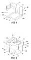
- FIG. 5is a perspective view of an embodiment of a solid ink stick.
- FIG. 6is another perspective view of the ink stick of FIG. 5 .
- FIG. 7is a simplified cross-sectional view of a feed channel taken along line 7 — 7 of FIG. 3 .
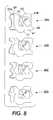
- FIG. 8is a top elevational view of a set of solid ink sticks.
- FIG. 1shows a solid ink, or phase change, ink printer 10 that includes an outer housing having a top surface 12 and side surfaces 14 .
- a user interfacesuch as a front panel display screen 16 , displays information concerning the status of the printer, and user instructions. Buttons 18 or other control elements for controlling operation of the printer are adjacent the front panel display screen, or may be at other locations on the printer.
- An ink jet printing mechanism(not shown) is contained inside the housing. Such a printing mechanism is described in U.S. Pat. No. 5,805,191, entitled Surface Application System, to Jones et al., and U.S. Pat. No. 5,455,604, entitled Ink Jet Printer Architecture and Method, to Adams et al.
- An ink feed systemdelivers ink to the printing mechanism.
- the ink feed systemis contained under the top surface of the printer housing.
- the top surface of the housingincludes a hinged ink access cover 20 that opens as shown in FIG. 2, to provide the operator access to the ink feed system.
- the ink access cover 20is attached to an ink load linkage element 22 so that when the printer ink access cover 20 is raised, the ink load linkage 22 slides and pivots to an ink load position.
- the interaction of the ink access cover and the ink load linkage elementis described in U.S. Pat. No. 5,861,903 for an Ink Feed System, issued Jan. 19, 1999 to Crawford et al., though with some differences noted below.
- opening the ink access coverreveals a key plate 26 having keyed openings 24 A, 24 B, 24 C, 24 D.
- Each keyed opening 24 A, 24 B, 24 C, 24 Dprovides access to an insertion end of one of several individual feed channels 28 A, 28 B, 28 C, 28 D of the solid ink feed system (see FIGS. 2 and 3 ).
- Each longitudinal feed channel 28delivers ink sticks 30 of one particular color to a corresponding melt plate 32 .
- Each feed channelhas a longitudinal feed direction from the insertion end of the feed channel to the melt end of the feed channel.
- the melt end of the feed channelis adjacent the melt plate.
- the melt platemelts the solid ink stick into a liquid form.
- the melted inkdrips through a gap 33 between the melt end of the feed channel and the melt plate, and into a liquid ink reservoir (not shown).
- the feed channels 28have a longitudinal dimension from the insertion end to the melt end, and a lateral dimension, substantially perpendicular to the longitudinal dimension.
- Each feed channel in the particular embodiment illustratedincludes a push block 34 driven by a driving force or element, such as a constant force spring 36 , to push the individual ink sticks along the length of the longitudinal feed channel toward the melt plates 32 that are at the melt end of each feed channel.
- the tension of the constant force spring 36drives the push block toward the melt end of the feed channel.
- the ink load linkage 22is coupled to a yoke 38 , which is attached to the constant force spring 36 mounted in the push block 34 . The attachment to the ink load linkage 22 pulls the push block 34 toward the insertion end of the feed channel when the ink access cover is raised to reveal the key plate 26 .
- the constant force spring 36can be a flat spring with its face oriented along a substantially vertical axis.
- FIG. 4is a cross-sectional view of an exemplary feed chute comprising a set of feed channels 28 .
- FIG. 4is a cross-sectional view of an exemplary feed chute comprising a set of feed channels 28 .
- a color printertypically uses four colors of ink (yellow, cyan, magenta, and black).
- Ink sticks 30 of each colorare delivered through a corresponding individual one of the feed channels 28 .
- the operator of the printerexercises care to avoid inserting ink sticks of one color into a feed channel for a different color.
- Ink sticksmay be so saturated with color dye that it may be difficult for a printer operator to tell by the apparent color alone of the ink sticks which color is which. Cyan, magenta, and black ink sticks in particular can be difficult to distinguish visually based on color appearance.
- the key plate 26has keyed openings 24 A, 24 B, 24 C, 24 D to aid the printer operator in ensuring that only ink sticks of the proper color are inserted into each feed channel.
- Each keyed opening 24 A, 24 B, 24 C, 24 D of the key platehas a unique shape.
- the Ink sticks 30 of the color for that feed channelhave a shape corresponding to the shape of the keyed opening.
- the keyed openings and corresponding ink stick shapesexclude from each ink feed channel ink sticks of all colors except the ink sticks of the proper color for that feed channel.
- FIGS. 5 and 6An exemplary solid ink stick 30 for use in the feed system is illustrated in FIGS. 5 and 6.
- the ink stickis formed of a three dimensional ink stick body.
- the ink stick body illustratedhas a bottom surface 52 and a top surface 54 that are substantially parallel one another.
- the surfaces of the ink stick bodyneed not be flat, nor need they be parallel or perpendicular one another. However, these descriptions will aid the reader in visualizing, even though the surfaces may have three dimensional topography, or be angled with respect to one another.
- the ink stick bodyalso has a plurality of side extremities, such as side surfaces 56 A, 56 B, 61 , 62 .
- the illustrated embodimentincludes four side surfaces, including two end surfaces 61 , 62 and two lateral side surfaces 56 A, 56 B.
- the basic elements of the lateral side surfaces 56 Aare substantially parallel one another, and are substantially perpendicular to the top and bottom surfaces 52 , 54 .
- the end surfaces 61 , 62are also basically substantially parallel one another, and substantially perpendicular to the top and bottom surfaces, and to the lateral side surfaces.
- One of the end surfaces 61is a leading end surface, and the other end surface 62 is a trailing end surface.
- the basic side surfaces 56 A, 56 B and the end surfaces 61 , 62are modified with key and other shaping elements, as described in greater detail below.
- the ink stick bodymay be formed by pour molding, injection molding, compression molding, or other known techniques.
- the lateral side surfacesare illustrated with a stepped arrangement.
- the lower portions of the lateral side surfacesare closer to one another than are the upper portions of the lateral side surfaces, so that the lower portion of the ink stick body is narrower than the upper portion.
- the lateral side surfaces of the ink stick bodycan be substantially vertical, so that the ink stick body has a substantially uniform horizontal cross section.
- the lateral side surfacescould slant, giving the ink stick body a tapered shape from top to bottom.
- the leading and trailing end surfaceshave complementary non-planar shapes or contours. These contours may be defined by a plurality of straight lines connecting the top surface and the bottom surface along each of the end surfaces of the ink stick body, or by a plurality of curved lines connecting the top and bottom surfaces of the ink stick body.
- the non-planar contour of the first end surface 61forms a projecting key or nesting element 71 .
- the non-planar contour of the opposite end surface 62forms a recessed key or nesting element 72 .
- the complementary shapes 71 , 72nest with one another when two ink sticks are placed adjacent one another with the first end surface of one ink stick abutting the second end surface of an adjacent ink stick in the ink channel.
- the illustrated ink stick bodyincludes a protruding nesting element on the leading end surface of the ink stick, and a complementary recessed nesting element on the trailing end surface of the ink stick body.
- the protruding nesting elementmay also be on the trailing end surface, with the complementary recessed nesting element on the leading end surface.
- the illustrated implementationhas the complementary contours extending the entire height of the ink stick body from the top surface to the bottom surface.
- Alternative embodimentsmay have the projections and indentations extending only along a portion of the height of the ink stick body end surfaces 61 , 62 .
- the projecting and recessed elements 71 , 72 on the end surfaces 61 , 62 of the ink stick bodycan also be insertion key elements in cooperation with the appropriately shaped keyed openings 24 A, 24 B, 24 C, 24 D in the key plate 26 .
- the ink stickalso includes guide means for guiding the ink stick along the feed channel 28 (see FIGS. 4 and 7 ).
- the ink stick bodyhas a lateral center of gravity 63 between the two lateral side surfaces 56 , and a vertical center of gravity 64 between the top surface 54 and the bottom surface 52 of the ink stick body. If the weight distribution of the ink stick body is substantially uniform, and the ink stick body is substantially symmetrical about its lateral center, the lateral center of gravity 63 is approximately at the midpoint between the lateral side surfaces of the ink stick body. The lateral center of gravity can often be determined without accounting for the insertion key elements formed in the lateral side surfaces of the ink stick body.
- the ink stick guide meansincludes a lower guide element 66 formed in the ink stick body, below the vertical center of gravity.
- the lower guide element 66interacts with a feed channel guide rail 40 in the feed channel for guiding the ink stick along the feed channel.
- the lower guide element 66 shownis formed in the bottom surface 52 of the ink stick body as a protrusion from the bottom surface.
- the lower guide elementis laterally offset from the lateral center of gravity 63 of the ink stick body, and may be adjacent one of the lateral sides of the ink stick body.
- the protruding guide elementis formed at or near a lateral edge 58 A of the bottom surface formed by the intersection of the bottom surface 52 and one of the lateral side surfaces 56 A of the ink stick body.
- the protruding lower guide elementcan extend along the length of the ink stick body, from the first end surface 61 to the second end surface 62 .
- the lower guide element 66has a lateral dimension of approximately 0.12 inches (3.0 mm) and protrudes approximately 0.08-0.2 inches (2.0-5.0 mm) from the bottom surface of the ink stick body.
- the protruding lower guide elementtapers from its proximal base, where it joins the main ink stick body, to its distal tip.
- the distal tip of the lower guide elementmay be somewhat rounded, or otherwise shaped to complement the guide rail in the lower portion of the ink feed channel.
- the lower guide element 66 of the ink stickslidingly engages the guide rail 40 to guide the ink stick along the feed channel.
- the protruding lower guide elementneed not be continuous along the entire length of the ink stick body.
- the lower guide elementcan also be recessed into the bottom surface of the ink stick body.
- the guide rail 40is raised to function with such a recessed lower guide element.
- the guide rail 40 and the lower guide element 66are formed with compatible shapes, and may for example have complementary shapes.
- the ink stick bodyadditionally includes an upper guide element 68 that guides a portion of the ink stick body along an upper guide rail 48 in the feed channel and forms an additional portion of the ink stick guide means.
- the upper guide element 68 of the ink stickis formed above the vertical center of gravity 64 of the ink stick body, on the opposite side of the lateral center of gravity 63 from the lower guide element 66 .
- the upper guide elementmay be a portion of the lateral extremity or side surface of the ink stick body.
- the lateral extremity side surface 56 B containing the upper guide element 68also intersects the bottom surface 52 of the ink stick body on the lateral edge of the bottom surface opposite the lateral edge nearest the lower guide element 66 .
- the upper edge of the lateral side extremity or surface 56 B forming the upper guide element 68corresponds to the surface lateral edge 58 B opposite the lateral edge 58 A nearest the lower guide element 66 .
- the upper guide rail 48 of the feed channelmay be formed as part of the key plate 26 , or may be a part of the feed channel body.
- the upper guide rail of the feed channelis positioned so that the upper guide element 68 of the ink stick body exerts a small lateral force on the upper guide rail. This lateral force tends to minimize the engagement force between the upper guide element 68 of the ink stick and the upper guide rail 48 .
- the ink stickis guided using only two points or lines of contact—the lower guide element 66 on the lower guide rail 40 , and the upper guide element 68 on the upper guide rail 48 . This provides greater accuracy in guiding the ink stick along the feed channel, so that the ink stick retains its orientation in the feed channel as the ink stick progresses toward the melt plate 32 .
- the ink stick 30 illustrated in FIGS. 5 and 6has the upper portion of the ink stick body, adjacent the top surface 54 , formed to provide an outer perimeter that is formed with channel insertion key elements.
- the outer perimeter key elementsare formed to provide the top surface with a visually recognizable shape or symbol.
- a visually recognizable symbolis a shape that conveys recognizable meaning to a user to help the user identify the opening 24 A, 24 B, 24 C, 24 D through which to insert the ink stick.
- the particular ink stick shownhas the outer perimeter of the top surface 54 formed in the shape of the numeral “1.” As seen, a left segment of the perimeter 57 A of the ink stick forms the left portion of the symbol, while a right segment of the ink stick perimeter 57 B forms the right portion of the visually recognizable symbol.
- a set of ink sticks for a particular printercould include additional ink sticks having top surface outer perimeters in the shapes of the numerals “2,” “3,” and “4” is shown in FIG. 8 .
- the shaped lateral side surfacesprovide an ink channel insertion keying mechanism, as seen in FIG. 2 .
- the lateral edges of each keyed opening 24 A, 24 B, 24 C, 24 D through the key plate 26are correspondingly shaped so that the keyed opening admits an ink stick body having the requisite lateral perimeter segment shapes, while excluding ink stick bodies having other lateral perimeter segment shapes.
- the printer operatorcan easily associate an ink stick having a particular feed channel of the printer, either by correlating the symbol of the ink stick with the corresponding keyed opening in the key plate, or by correlating the symbol of the ink stick with the corresponding symbol that can be displayed adjacent the keyed opening.
- the visually recognizable symbol formed by the lateral perimeter segments of the ink stick bodyprovide an ink channel key that performs a color keying function for the printer by excluding from a particular channel of the printer ink sticks that are of the incorrect color.
- the visually recognizable shapes that identify the correct key plate opening, and thus the correct ink stick feed channel,are provided in both lateral side surfaces of the ink stick body.
- One side surface 56 A of the ink stick bodyis shaped with one side edge of the visually recognizable symbol
- the other lateral side surface 56 B of the ink stick bodyis shaped with the other side edge of the visually recognizable symbol.
- the individual insertion channel keying functioncan be provided with shapes that provide visually recognizable symbols other than numeric characters.
- a set of ink stickscould have perimeter segments that form visually recognizable alphabetical characters, such as the alphabetical characters are “C,” “Y,” “M,” and “K,” which printer operators will associate with the colors of the ink—C for cyan, Y for yellow, M for magenta, and K for black.
- Such alphabetical charactersare easy for the printer operator to associate with the proper feed channel for each color of ink.
- the ink stick perimetercan be formed into visually identifiable symbols other than alphanumeric characters, such as the suite shapes from common playing cards. With the present teaching, those skilled in the art will recognize that other symbols can also be used, such as the shapes of animals or other recognizable objects.
- the substantially horizontal top surface 54 of the ink stick bodycan further be embossed or debossed with a representation of the visually recognizable symbol 59 .
- other informationsuch as a brand marking for the ink can be embossed or debossed on the top surface 54 of the ink stick body.
- an additional perimeter segment of each ink stickis used to provide an additional insertion keying function.
- the additional insertion keying functionis a printer keying function that associates a set of ink sticks with a particular printer model.
- the printer keying functionis provided by providing a contour to at least a portion of the perimeter of the ink stick (when viewed from above).
- a common key elementis included throughout a set of ink sticks intended for a particular printer that permits those ink sticks to be inserted into the feed channels of that printer, but prevent those ink sticks from being inserted into an incorrect printer.
- the key element(s) 71 , 72are protrusions and indentations formed in the transverse end surface(s) that are substantially perpendicular to the lateral side surfaces.
- These transverse side surfacesmay be the leading and trailing end surfaces of the ink stick body, and are at least partially transverse to the longitudinal direction of the feed channel when the ink stick is placed in the feed channel.
- Each ink stick of the set of ink sticks shown in FIG. 8includes a key element of the same shape in the transverse side of the ink stick.
- a corresponding complementary key 73is included in the perimeter of each keyed opening 24 A, 24 B, 24 C, 24 D for that particular printer model.
- the particular key 73 shown in the key plate of the printer of FIG. 2corresponds to the key element 72 on the set of ink sticks shown in FIG. 8 .
- the first keying functionwhich in the illustrated example is performed by key elements on the lateral side segments 56 A, 56 B of the outer perimeter of the ink stick and corresponding lateral side edges of the keyed openings 24 A, 24 B, 24 C, 24 D, ensures that only ink sticks of the appropriate color are fed into each feed channel of the printer.
- the second keying functionwhich in the illustrated implementation is performed by key elements 71 , 72 in the transverse sides 61 , 62 of the ink sticks and the corresponding transverse edges of the keyed openings 24 A, 24 B, 24 C, 24 D, ensures that the ink sticks of all colors for a particular printer model can be inserted only into that printer.
- the printer feed system shown in FIG. 2is designed to admit the ink sticks of the ink stick set shown in FIG. 8 .
- the first ink stick 30 A of the set shown in FIG. 8fits through the first keyed opening 24 A of the feed system shown in FIG. 2, while the second ink stick 30 B of the set shown in FIG. 8 fits through the second keyed opening 24 B, and so forth.
- this additional keying functionprovides a mechanism to block ink intended for one printer from being inserted into an incompatible printer.
- This printer exclusion keying functionis provided by using different shapes for the common keys 73 in the keyed openings of the key plates 26 of different printers.
- the keys 73 along the traverse edges of each keyed opening of the feed system shown in FIG. 2exclude ink sticks having different shapes of key elements in their transverse sides.
- feed channel insertion key elementscan be included on multiple sides of the ink stick body.
- key elementscan be included on sides that are at least in part transverse to the longitudinal feed direction of the feed channel (are not parallel to the lateral sides of the ink stick). These transverse sides are either straight or curved, and can be perpendicular to the lateral sides, or be at some other angle.
- additional perimeter segmentsare available to include key elements, so that a greater variety of key shapes can be used.
- the envelope of the ink sticks illustrated in FIGS. 5-8, including contours, indentations, and protrusions for keying and alignment functionshas an aspect ratio in which the width of the ink stick body between the lateral side surfaces 56 A, 56 B is approximately equal to or greater than the longitudinal length of the ink stick body between the end surfaces 61 , 62 .
- the longitudinal length of the ink stick bodyis the dimension that is along (aligned with) a longitudinal feed channel, such as the feed channel 28 of the ink jet printer 10 of FIG. 2, when the ink stick is properly inserted into the feed channel.
- the width of the ink stick bodyis the dimension perpendicular to the length.
- the ratio of the width of the ink stick body to the lengthis between 1.0 and 1.5.
- the ratio of width to lengthis approximately 1.25.
- the length of the ink stick body 30 between the end surfaces 61 , 62is approximately 1.2 inches (30 mm), and the width between the lateral side surfaces 56 A, 56 B is approximately 1.5 inches (38 mm).
- the height of the ink stick body between the bottom surface 52 and the top surface 54can be significantly greater or less than either the length or the width.
- Each feed channel 28has sufficient length to hold at least two ink sticks.
- the push block 34 or gravity mechanismmoves the following ink sticks along the length of the ink stick feed channel, toward the melt plate.
- the operatormay wish to replenish the quantity of solid ink sticks in the teed channel (“top off” the ink supply).
- the printer operatorcan insert a new ink stick through the keyed opening into the feed channel 28 only if the last ink stick currently in the feed channel is clear of the keyed opening.
- the operatorhas greater flexibility to insert additional ink sticks if the ink sticks have a shorter longitudinal length relative to their width.
- the ink stick aspect ratio describedprovides greater solid ink density per unit length of the feed channel, and provides an enhanced ability to fill the feed channel as closely to the keyed opening as possible.
- an ink stick body with a substantially reduced dimension in at least one of the three orthogonal axesmay allow more uniform formation of the ink stick body.
- ink sticksmay be formed by inserting molten ink into a mold, and allowing the ink to cool, solidifying as it cools. Such cooling can occur more uniformly when the ink stick body has at least one dimension in the three axes such that the interior mass is closer to an exterior surface, so that it cools more readily.
- a feed keying element 50is provided in one of the surfaces of the ink stick body.
- the ink stick feed keying element 50permits the ink stick to pass a correspondingly shaped key 49 (FIGS. 3 and 4) in the feed channel as the ink stick 30 travels along the length of the feed channel.
- the feed channel key 49is a projection from the floor 46 or support rib of the feed channel
- the feed keying element in the ink stick bodyis a longitudinal recess formed in the bottom surface 52 of the ink stick body.
- the feed keying elementmay also be formed in one of the side surfaces 56 A, 56 B, or in the substantially horizontal top surface 54 of the ink stick body.
- feed keys of different sizes, shapes, and positionscan be used in different feed channels of a single printer to provide enhanced protection against an ink stick of the incorrect color reaching the melt plate 32 .
- Feed keyscan also be used to differentiate ink sticks intended for different models of printers.
- One type of feed keycan be placed in all the feed channels of a particular model printer. Ink sticks intended for that model printer contain a corresponding feed key element.
- a feed key of a different size, shape, or positionis placed in all feed channels of a different model printer.
- the different keyblocks ink sticks having a feed key element for the first model printer, while permitting ink sticks having a feed key element corresponding to the second feed key to pass.
Landscapes
- Ink Jet (AREA)
Abstract
Description
Claims (16)
Priority Applications (2)
| Application Number | Priority Date | Filing Date | Title |
|---|---|---|---|
| US10/135,156US6722764B2 (en) | 2002-04-29 | 2002-04-29 | Feed guidance and identification for ink stick |
| US10/811,197US6986570B2 (en) | 2002-04-29 | 2004-03-26 | Feed guidance and identification for ink stick |
Applications Claiming Priority (1)
| Application Number | Priority Date | Filing Date | Title |
|---|---|---|---|
| US10/135,156US6722764B2 (en) | 2002-04-29 | 2002-04-29 | Feed guidance and identification for ink stick |
Related Child Applications (1)
| Application Number | Title | Priority Date | Filing Date |
|---|---|---|---|
| US10/811,197DivisionUS6986570B2 (en) | 2002-04-29 | 2004-03-26 | Feed guidance and identification for ink stick |
Publications (2)
| Publication Number | Publication Date |
|---|---|
| US20030202071A1 US20030202071A1 (en) | 2003-10-30 |
| US6722764B2true US6722764B2 (en) | 2004-04-20 |
Family
ID=29249394
Family Applications (2)
| Application Number | Title | Priority Date | Filing Date |
|---|---|---|---|
| US10/135,156Expired - LifetimeUS6722764B2 (en) | 2002-04-29 | 2002-04-29 | Feed guidance and identification for ink stick |
| US10/811,197Expired - Fee RelatedUS6986570B2 (en) | 2002-04-29 | 2004-03-26 | Feed guidance and identification for ink stick |
Family Applications After (1)
| Application Number | Title | Priority Date | Filing Date |
|---|---|---|---|
| US10/811,197Expired - Fee RelatedUS6986570B2 (en) | 2002-04-29 | 2004-03-26 | Feed guidance and identification for ink stick |
Country Status (1)
| Country | Link |
|---|---|
| US (2) | US6722764B2 (en) |
Cited By (55)
| Publication number | Priority date | Publication date | Assignee | Title |
|---|---|---|---|---|
| US20050062820A1 (en)* | 2002-04-29 | 2005-03-24 | Xerox Corporation | Guide for solid ink stick feed |
| USD530366S1 (en)* | 2005-03-30 | 2006-10-17 | Xerox Corporation | Ink stick for phase change ink jet printer |
| USD530361S1 (en)* | 2003-12-17 | 2006-10-17 | Xerox Corporation | Printer |
| USD531211S1 (en)* | 2005-03-30 | 2006-10-31 | Xerox Corporation | Ink stick for phase change ink jet printer |
| USD533586S1 (en)* | 2003-05-07 | 2006-12-12 | Ricoh Company, Ltd. | Color laser printer |
| USD533900S1 (en)* | 2005-09-22 | 2006-12-19 | Xerox Corporation | Ink stick for phase change ink jet printer |
| USD534205S1 (en)* | 2005-07-14 | 2006-12-26 | Provo Craft And Novelty, Inc. | Electronic cutter |
| USD534580S1 (en)* | 2005-03-30 | 2007-01-02 | Xerox Corporation | Ink stick for phase change ink jet printer |
| USD534949S1 (en)* | 2005-03-30 | 2007-01-09 | Xerox Corporation | Ink stick for phase change ink jet printer |
| USD537874S1 (en)* | 2005-03-30 | 2007-03-06 | Xerox Corporation | Ink stick for phase change ink jet printer |
| USD537873S1 (en)* | 2005-03-30 | 2007-03-06 | Xerox Corporation | Ink stick for phase change ink jet printer |
| USD538848S1 (en)* | 2005-03-30 | 2007-03-20 | Xerox Corporation | Ink stick for phase change ink jet printer |
| USD559901S1 (en)* | 2006-09-15 | 2008-01-15 | Xerox Corporation | Ink stick for a phase change ink jet printer |
| USD566171S1 (en)* | 2006-09-15 | 2008-04-08 | Xerox Corporation | Ink stick for a phase change ink jet printer |
| US20080088688A1 (en)* | 2006-10-17 | 2008-04-17 | Xerox Corporation | Ink loader mechanism using an ink stick carrier |
| US20080088686A1 (en)* | 2006-10-17 | 2008-04-17 | Xerox Corporation | Collapsible ink loader feed support |
| US20080088687A1 (en)* | 2006-10-17 | 2008-04-17 | Xerox Corporation | Replaceable ink stick guides and supports |
| USD569419S1 (en)* | 2006-09-15 | 2008-05-20 | Xerox Corporation | Ink stick for a phase change ink jet printer |
| US20080117266A1 (en)* | 2006-11-21 | 2008-05-22 | Xerox Corporation | Transport system for solid ink for cooperation with melt head in a printer |
| US20080117264A1 (en)* | 2006-11-21 | 2008-05-22 | Xerox Corporation | Solid ink stick features for printer ink transport and method |
| US20080117272A1 (en)* | 2006-11-21 | 2008-05-22 | Xerox Corporation | Printer solid ink transport and method |
| US20080122908A1 (en)* | 2006-11-28 | 2008-05-29 | Xerox Corporation | Intermediate side slot vertical ink constraint with offset support |
| US20080122909A1 (en)* | 2006-11-28 | 2008-05-29 | Xerox Corporation | Lateral anti-skewing solution for solid ink |
| USD570407S1 (en)* | 2006-09-15 | 2008-06-03 | Xerox Corporation | Ink stick for a phase change ink jet printer |
| USD570406S1 (en)* | 2006-09-15 | 2008-06-03 | Xerox Corporation | Ink stick for a phase change ink jet printer |
| US20080136882A1 (en)* | 2006-12-12 | 2008-06-12 | Xerox Corporation | Solid ink stick chute for printer solid ink transport with mating solid ink stick chute |
| US20080151024A1 (en)* | 2006-12-22 | 2008-06-26 | Xerox Corporation | System for loading ink sticks configured for lateral anti-skewing |
| US20080204532A1 (en)* | 2007-02-28 | 2008-08-28 | Xerox Corporation | System for loading and feeding solid ink sticks to an ink melter in a phase change ink printer |
| USD576204S1 (en)* | 2007-07-18 | 2008-09-02 | Xerox Corporation | Ink stick for a phase change ink jet printer |
| USD576205S1 (en)* | 2007-07-18 | 2008-09-02 | Xerox Corporation | Ink stick for a phase change ink jet printer |
| USD582975S1 (en)* | 2007-07-18 | 2008-12-16 | Xerox Corporation | Ink stick for a phase change ink jet printer |
| USD582976S1 (en)* | 2007-07-18 | 2008-12-16 | Xerox Corporation | Ink stick for a phase change ink jet printer |
| USD585089S1 (en)* | 2007-07-18 | 2009-01-20 | Xerox Corporation | Ink stick for a phase change ink jet printer |
| USD585487S1 (en)* | 2007-07-18 | 2009-01-27 | Xerox Corporation | Ink stick for a phase change ink jet printer |
| USD586387S1 (en)* | 2007-07-18 | 2009-02-10 | Xerox Corporation | Ink stick for a phase change ink jet printer |
| USD586386S1 (en)* | 2007-07-18 | 2009-02-10 | Xerox Corporation | Ink stick for a phase change ink jet printer |
| US20090160919A1 (en)* | 2007-12-21 | 2009-06-25 | Xerox Corporation | System for delivering solid ink through a feed channel having non-linear sections |
| US20090185016A1 (en)* | 2008-01-18 | 2009-07-23 | Xerox Corporation | Transport System Having Multiple Moving Forces For Solid Ink Delivery In A Printer |
| US20090207219A1 (en)* | 2008-02-14 | 2009-08-20 | Xerox Corporation | Mechanized Feed Channel Barrier In A Solid Ink Printer |
| US20090213196A1 (en)* | 2008-02-27 | 2009-08-27 | Xerox Corporation | Transport System Having Single Insertion Port For Solid Ink Delivery In A Printer |
| US20090225117A1 (en)* | 2008-03-06 | 2009-09-10 | Xerox Corporation | System And Method For Processing Solid Ink Stick Exception Conditions In A Solid Ink Printer |
| USD610609S1 (en)* | 2006-11-21 | 2010-02-23 | Xerox Corporation | Solid ink stick for an ink jet printer |
| USD610610S1 (en)* | 2006-11-21 | 2010-02-23 | Xerox Corporation | Solid ink stick for an ink jet printer |
| USD610608S1 (en)* | 2006-11-21 | 2010-02-23 | Xerox Corporation | Solid ink stick for an ink jet printer |
| US7794072B2 (en) | 2006-11-21 | 2010-09-14 | Xerox Corporation | Guide for printer solid ink transport and method |
| US7798624B2 (en) | 2006-11-21 | 2010-09-21 | Xerox Corporation | Transport system for solid ink in a printer |
| US7976118B2 (en) | 2007-10-22 | 2011-07-12 | Xerox Corporation | Transport system for providing a continuous supply of solid ink to a melting assembly in a printer |
| USD644266S1 (en)* | 2010-09-27 | 2011-08-30 | Xerox Corporation | Ink stick for a phase change ink jet printer |
| USD661729S1 (en)* | 2010-09-28 | 2012-06-12 | Xerox Corporation | Office machine |
| US8240831B2 (en) | 2010-06-17 | 2012-08-14 | Xerox Corporation | System and method for controlling insertion of solid ink sticks into a printer |
| US8240830B2 (en) | 2010-03-10 | 2012-08-14 | Xerox Corporation | No spill, feed controlled removable container for delivering pelletized substances |
| US8727478B2 (en) | 2012-10-17 | 2014-05-20 | Xerox Corporation | Ink loader having optical sensors to identify solid ink sticks |
| US8777386B2 (en) | 2012-10-17 | 2014-07-15 | Xerox Corporation | Solid ink stick having identical identifying features on a plurality of edges |
| US8814336B2 (en) | 2011-12-22 | 2014-08-26 | Xerox Corporation | Solid ink stick configuration |
| US8876265B2 (en) | 2012-06-28 | 2014-11-04 | Xerox Corporation | Ink stick transport system |
Families Citing this family (23)
| Publication number | Priority date | Publication date | Assignee | Title |
|---|---|---|---|---|
| US6739713B2 (en) | 2002-04-29 | 2004-05-25 | Xerox Corporation | Guide for solid ink stick feed |
| USD500786S1 (en) | 2003-12-08 | 2005-01-11 | Xerox Corporation | Ink stick for phase change ink jet printer |
| USD544535S1 (en) | 2003-12-08 | 2007-06-12 | Xerox Corporation | Ink stick for phase change ink jet printer |
| USD505973S1 (en) | 2003-12-08 | 2005-06-07 | Xerox Corporation | Ink stick for phase change ink jet printer |
| USD506779S1 (en) | 2003-12-08 | 2005-06-28 | Xerox Corporation | Ink stick for phase change ink jet printer |
| USD500784S1 (en) | 2003-12-08 | 2005-01-11 | Xerox Corporation | Ink stick for phase change ink jet printer |
| USD500785S1 (en) | 2003-12-08 | 2005-01-11 | Xerox Corporation | Ink stick for phase change ink jet printer |
| USD500783S1 (en) | 2003-12-08 | 2005-01-11 | Xerox Corporation | Ink stick for phase change ink jet printer |
| USD506778S1 (en) | 2003-12-08 | 2005-06-28 | Xerox Corporation | Ink stick for phase change ink jet printer |
| USD505974S1 (en) | 2003-12-08 | 2005-06-07 | Xerox Corporation | Ink stick for phase change ink jet printer |
| USD500516S1 (en) | 2003-12-08 | 2005-01-04 | Xerox Corporation | Ink stick for phase change ink jet printer |
| US7690775B2 (en)* | 2006-11-07 | 2010-04-06 | Xerox Corporation | Solid ink sticks with corner guides |
| US7854501B2 (en)* | 2006-11-07 | 2010-12-21 | Xerox Corporation | Common side insertion keying for phase change ink sticks |
| US7810918B2 (en)* | 2006-11-07 | 2010-10-12 | Xerox Corporation | One way compatibility keying for solid ink sticks |
| US7780283B2 (en)* | 2006-11-07 | 2010-08-24 | Xerox Corporation | Independent keying and guidance for solid ink sticks |
| US8016403B2 (en)* | 2007-10-03 | 2011-09-13 | Xerox Corporation | Solid ink stick with visual orientation indicator |
| US7857440B2 (en)* | 2008-01-18 | 2010-12-28 | Xerox Corporation | Visual identification of solid ink sticks |
| US7837317B2 (en)* | 2008-02-15 | 2010-11-23 | Xerox Corporation | Solid ink stick with witness mark |
| US8366255B2 (en)* | 2010-06-02 | 2013-02-05 | Xerox Corporation | Solid ink stick with retrieval feature |
| USD656984S1 (en)* | 2010-09-27 | 2012-04-03 | Xerox Corporation | Ink stick for a phase change ink jet printer |
| USD644689S1 (en)* | 2010-09-27 | 2011-09-06 | Xerox Corporation | Ink stick for a phase change ink jet printer |
| AU2013204785C1 (en) | 2012-07-09 | 2019-09-05 | Fin Control Systems Pty. Limited | Fin Plug for Water Craft |
| AU2013204755A1 (en) | 2012-11-14 | 2014-05-29 | Fin Control Systems Pty. Limited | A Fin Plug for a Water Craft |
Citations (6)
| Publication number | Priority date | Publication date | Assignee | Title |
|---|---|---|---|---|
| US5442387A (en) | 1991-06-17 | 1995-08-15 | Tektronix, Inc. | Apparatus for supplying phase change ink to an ink jet printer |
| US5455604A (en) | 1991-04-29 | 1995-10-03 | Tektronix, Inc. | Ink jet printer architecture and method |
| US5734402A (en) | 1996-03-07 | 1998-03-31 | Tekronix, Inc. | Solid ink stick feed system |
| US5805191A (en) | 1992-11-25 | 1998-09-08 | Tektronix, Inc. | Intermediate transfer surface application system |
| US5861903A (en) | 1996-03-07 | 1999-01-19 | Tektronix, Inc. | Ink feed system |
| US6053608A (en)* | 1996-07-24 | 2000-04-25 | Brother Kogyo Kabushiki Kaisha | Ink pellet with step configuration including slidable bearing surfaces |
Family Cites Families (13)
| Publication number | Priority date | Publication date | Assignee | Title |
|---|---|---|---|---|
| US5917528A (en)* | 1996-09-05 | 1999-06-29 | Tektronix, Inc. | Solid ink stick supply apparatus and method |
| US6755517B2 (en)* | 2002-04-29 | 2004-06-29 | Xerox Corporation | Alignment feature for solid ink stick |
| US20030202056A1 (en)* | 2002-04-29 | 2003-10-30 | Xerox Corporation | Multiple segment keying for solid ink stick feed |
| US6761444B2 (en)* | 2002-04-29 | 2004-07-13 | Xerox Corporation | Channel keying for solid ink stick insertion |
| US6874880B2 (en)* | 2002-04-29 | 2005-04-05 | Xerox Corporation | Solid ink stick with identifiable shape |
| US6719419B2 (en)* | 2002-04-29 | 2004-04-13 | Xerox Corporation | Feed channel keying for solid ink stick feed |
| US6893121B2 (en)* | 2002-04-29 | 2005-05-17 | Xerox Corporaton | Solid ink stick set identification |
| US6739713B2 (en)* | 2002-04-29 | 2004-05-25 | Xerox Corporation | Guide for solid ink stick feed |
| US6840613B2 (en)* | 2002-04-29 | 2005-01-11 | Xerox Corporation | Guide for solid ink stick feed |
| US6857732B2 (en)* | 2002-04-29 | 2005-02-22 | Xerox Corporation | Visible identification of solid ink stick |
| US6840612B2 (en)* | 2002-04-29 | 2005-01-11 | Xerox Corporation | Guide for solid ink stick feed |
| US20030202066A1 (en)* | 2002-04-29 | 2003-10-30 | Xerox Corporation | Solid ink stick with efficient aspect ratio |
| US6672716B2 (en)* | 2002-04-29 | 2004-01-06 | Xerox Corporation | Multiple portion solid ink stick |
- 2002
- 2002-04-29USUS10/135,156patent/US6722764B2/ennot_activeExpired - Lifetime
- 2004
- 2004-03-26USUS10/811,197patent/US6986570B2/ennot_activeExpired - Fee Related
Patent Citations (6)
| Publication number | Priority date | Publication date | Assignee | Title |
|---|---|---|---|---|
| US5455604A (en) | 1991-04-29 | 1995-10-03 | Tektronix, Inc. | Ink jet printer architecture and method |
| US5442387A (en) | 1991-06-17 | 1995-08-15 | Tektronix, Inc. | Apparatus for supplying phase change ink to an ink jet printer |
| US5805191A (en) | 1992-11-25 | 1998-09-08 | Tektronix, Inc. | Intermediate transfer surface application system |
| US5734402A (en) | 1996-03-07 | 1998-03-31 | Tekronix, Inc. | Solid ink stick feed system |
| US5861903A (en) | 1996-03-07 | 1999-01-19 | Tektronix, Inc. | Ink feed system |
| US6053608A (en)* | 1996-07-24 | 2000-04-25 | Brother Kogyo Kabushiki Kaisha | Ink pellet with step configuration including slidable bearing surfaces |
Non-Patent Citations (14)
| Title |
|---|
| Jones et al., "Alignment Feature for Solid Ink Stick," U.S. patent application Ser. No. XX/XXX,XXX (Attorney Docket No. D/A1673), filed concurrently herewith. |
| Jones et al., "Channel Keying for Solid Ink Insertion," U.S. patent application Ser. No. XX/XXX,XXX (Attorney Docket No. D/A2040), filed concurrently herewith. |
| Jones et al., "Channel Keying for Solid Ink Stick Feed," U.S. patent application Ser. No. XX/XXX,XXX (Attorney Docket No. D/A2031), filed concurrently herewith. |
| Jones et al., "Guide for Solid Ink Stick Feed," U.S. patent application Ser. No. XX/XXX,XXX (Attorney Docket No. D/A1664), filed concurrently herewith. |
| Jones et al., "Guide for Solid Ink Stick Feed," U.S. patent application Ser. No. XX/XXX,XXX (Attorney Docket No. D/A1664Q), filed concurrently herewith. |
| Jones et al., "Multiple Segment Keying for Solid Ink Stick Feed," U.S. patent application Ser. No. XX/XXX,XXX (Attorney Docket No. D/A2033Q), filed concurrently herewith. |
| Jones et al., "Solid Ink Stick with Efficient Aspect Ratio," U.S. patent application Ser. No. XX/XXX,XXX (Attorney Docket No. D/A1673Q), filed concurrently herewith. |
| Jones et al., "Solid Ink Stick with Identifiable Shape," U.S. patent application Ser. No. XX/XXX,XXX (Attorney Docket No. D/A2031Q), filed concurrently herewith. |
| Jones et al., "Visible Identification of Solid Ink Stick ," U.S. patent application Ser. No. XX/XXX,XXX (Attorney Docket No. D/A2032), filed concurrently herewith. |
| Jones, "Guide for Solid Ink Stick Feed," U.S. patent application Ser. No. XX/XXX,XXX (Attorney Docket No. D/A2010), filed concurrently herewith. |
| Jones, "Multiple Portion Solid Ink Stick," U.S. patent application Ser. No. XX/XXX,XXX (Attorney Docket No. D/A2031Q1), filed concurrently herewith. |
| Jones, "Solid Ink Stick Set Identification," U.S. patent application Ser. No. XX/XXX,XXX (Attorney Docket No. D/A2010Q1), filed concurrently herewith. |
| Merriam Webster's Collegiate Dictionary Tenth Edition; nest; p. 778.** |
| Summary of Tektronix/Xerox Corporation Solid Ink Stick Products sold at least one year prior to Apr. 29, 2002. |
Cited By (72)
| Publication number | Priority date | Publication date | Assignee | Title |
|---|---|---|---|---|
| US7066589B2 (en) | 2002-04-29 | 2006-06-27 | Xerox Corporation | Guide for solid ink stick feed |
| US20050062820A1 (en)* | 2002-04-29 | 2005-03-24 | Xerox Corporation | Guide for solid ink stick feed |
| USD533586S1 (en)* | 2003-05-07 | 2006-12-12 | Ricoh Company, Ltd. | Color laser printer |
| USD530361S1 (en)* | 2003-12-17 | 2006-10-17 | Xerox Corporation | Printer |
| USD538848S1 (en)* | 2005-03-30 | 2007-03-20 | Xerox Corporation | Ink stick for phase change ink jet printer |
| USD530366S1 (en)* | 2005-03-30 | 2006-10-17 | Xerox Corporation | Ink stick for phase change ink jet printer |
| USD531211S1 (en)* | 2005-03-30 | 2006-10-31 | Xerox Corporation | Ink stick for phase change ink jet printer |
| USD534580S1 (en)* | 2005-03-30 | 2007-01-02 | Xerox Corporation | Ink stick for phase change ink jet printer |
| USD534949S1 (en)* | 2005-03-30 | 2007-01-09 | Xerox Corporation | Ink stick for phase change ink jet printer |
| USD537874S1 (en)* | 2005-03-30 | 2007-03-06 | Xerox Corporation | Ink stick for phase change ink jet printer |
| USD537873S1 (en)* | 2005-03-30 | 2007-03-06 | Xerox Corporation | Ink stick for phase change ink jet printer |
| USD534205S1 (en)* | 2005-07-14 | 2006-12-26 | Provo Craft And Novelty, Inc. | Electronic cutter |
| USD533900S1 (en)* | 2005-09-22 | 2006-12-19 | Xerox Corporation | Ink stick for phase change ink jet printer |
| USD559901S1 (en)* | 2006-09-15 | 2008-01-15 | Xerox Corporation | Ink stick for a phase change ink jet printer |
| USD566171S1 (en)* | 2006-09-15 | 2008-04-08 | Xerox Corporation | Ink stick for a phase change ink jet printer |
| USD569419S1 (en)* | 2006-09-15 | 2008-05-20 | Xerox Corporation | Ink stick for a phase change ink jet printer |
| USD570407S1 (en)* | 2006-09-15 | 2008-06-03 | Xerox Corporation | Ink stick for a phase change ink jet printer |
| USD570406S1 (en)* | 2006-09-15 | 2008-06-03 | Xerox Corporation | Ink stick for a phase change ink jet printer |
| US20080088688A1 (en)* | 2006-10-17 | 2008-04-17 | Xerox Corporation | Ink loader mechanism using an ink stick carrier |
| US20080088686A1 (en)* | 2006-10-17 | 2008-04-17 | Xerox Corporation | Collapsible ink loader feed support |
| US20080088687A1 (en)* | 2006-10-17 | 2008-04-17 | Xerox Corporation | Replaceable ink stick guides and supports |
| US7594716B2 (en) | 2006-10-17 | 2009-09-29 | Xerox Corporation | Collapsible ink loader feed support |
| US7641327B2 (en) | 2006-10-17 | 2010-01-05 | Xerox Corporation | Replaceable ink stick guides and supports |
| US7695126B2 (en) | 2006-10-17 | 2010-04-13 | Xerox Corporation | Ink loader mechanism using an ink stick carrier |
| US20080117264A1 (en)* | 2006-11-21 | 2008-05-22 | Xerox Corporation | Solid ink stick features for printer ink transport and method |
| US7798624B2 (en) | 2006-11-21 | 2010-09-21 | Xerox Corporation | Transport system for solid ink in a printer |
| US20080117266A1 (en)* | 2006-11-21 | 2008-05-22 | Xerox Corporation | Transport system for solid ink for cooperation with melt head in a printer |
| USD610609S1 (en)* | 2006-11-21 | 2010-02-23 | Xerox Corporation | Solid ink stick for an ink jet printer |
| CN101200139B (en)* | 2006-11-21 | 2011-08-31 | 施乐公司 | Solid ink stick |
| US7976144B2 (en) | 2006-11-21 | 2011-07-12 | Xerox Corporation | System and method for delivering solid ink sticks to a melting device through a non-linear guide |
| US7883195B2 (en)* | 2006-11-21 | 2011-02-08 | Xerox Corporation | Solid ink stick features for printer ink transport and method |
| USD610610S1 (en)* | 2006-11-21 | 2010-02-23 | Xerox Corporation | Solid ink stick for an ink jet printer |
| USD610608S1 (en)* | 2006-11-21 | 2010-02-23 | Xerox Corporation | Solid ink stick for an ink jet printer |
| US20080117272A1 (en)* | 2006-11-21 | 2008-05-22 | Xerox Corporation | Printer solid ink transport and method |
| US7794072B2 (en) | 2006-11-21 | 2010-09-14 | Xerox Corporation | Guide for printer solid ink transport and method |
| US7753511B2 (en) | 2006-11-28 | 2010-07-13 | Xerox Corporation | Lateral anti-skewing solution for solid ink |
| US7726797B2 (en) | 2006-11-28 | 2010-06-01 | Xerox Corporation | Intermediate side slot vertical ink constraint with offset support |
| US20080122909A1 (en)* | 2006-11-28 | 2008-05-29 | Xerox Corporation | Lateral anti-skewing solution for solid ink |
| US20080122908A1 (en)* | 2006-11-28 | 2008-05-29 | Xerox Corporation | Intermediate side slot vertical ink constraint with offset support |
| US7878636B2 (en)* | 2006-12-12 | 2011-02-01 | Xerox Corporation | Solid ink stick chute for printer solid ink transport with mating solid ink stick chute |
| US20080136882A1 (en)* | 2006-12-12 | 2008-06-12 | Xerox Corporation | Solid ink stick chute for printer solid ink transport with mating solid ink stick chute |
| US7722177B2 (en) | 2006-12-22 | 2010-05-25 | Xerox Corporation | System for loading ink sticks configured for lateral anti-skewing |
| US20080151024A1 (en)* | 2006-12-22 | 2008-06-26 | Xerox Corporation | System for loading ink sticks configured for lateral anti-skewing |
| US7798626B2 (en) | 2007-02-28 | 2010-09-21 | Xerox Corporation | System for loading and feeding solid ink sticks to an ink melter in a phase change ink printer |
| US20080204532A1 (en)* | 2007-02-28 | 2008-08-28 | Xerox Corporation | System for loading and feeding solid ink sticks to an ink melter in a phase change ink printer |
| USD576205S1 (en)* | 2007-07-18 | 2008-09-02 | Xerox Corporation | Ink stick for a phase change ink jet printer |
| USD576204S1 (en)* | 2007-07-18 | 2008-09-02 | Xerox Corporation | Ink stick for a phase change ink jet printer |
| USD586386S1 (en)* | 2007-07-18 | 2009-02-10 | Xerox Corporation | Ink stick for a phase change ink jet printer |
| USD586387S1 (en)* | 2007-07-18 | 2009-02-10 | Xerox Corporation | Ink stick for a phase change ink jet printer |
| USD585487S1 (en)* | 2007-07-18 | 2009-01-27 | Xerox Corporation | Ink stick for a phase change ink jet printer |
| USD585089S1 (en)* | 2007-07-18 | 2009-01-20 | Xerox Corporation | Ink stick for a phase change ink jet printer |
| USD582976S1 (en)* | 2007-07-18 | 2008-12-16 | Xerox Corporation | Ink stick for a phase change ink jet printer |
| USD582975S1 (en)* | 2007-07-18 | 2008-12-16 | Xerox Corporation | Ink stick for a phase change ink jet printer |
| US7976118B2 (en) | 2007-10-22 | 2011-07-12 | Xerox Corporation | Transport system for providing a continuous supply of solid ink to a melting assembly in a printer |
| US20090160919A1 (en)* | 2007-12-21 | 2009-06-25 | Xerox Corporation | System for delivering solid ink through a feed channel having non-linear sections |
| US7883196B2 (en) | 2007-12-21 | 2011-02-08 | Xerox Corporation | System for delivering solid ink through a feed channel having non-linear sections |
| US7887173B2 (en) | 2008-01-18 | 2011-02-15 | Xerox Corporation | Transport system having multiple moving forces for solid ink delivery in a printer |
| US20090185016A1 (en)* | 2008-01-18 | 2009-07-23 | Xerox Corporation | Transport System Having Multiple Moving Forces For Solid Ink Delivery In A Printer |
| US8272727B2 (en) | 2008-02-14 | 2012-09-25 | Xerox Corporation | Mechanized feed channel barrier in a solid ink printer |
| US20090207219A1 (en)* | 2008-02-14 | 2009-08-20 | Xerox Corporation | Mechanized Feed Channel Barrier In A Solid Ink Printer |
| US20090213196A1 (en)* | 2008-02-27 | 2009-08-27 | Xerox Corporation | Transport System Having Single Insertion Port For Solid Ink Delivery In A Printer |
| US7883197B2 (en) | 2008-02-27 | 2011-02-08 | Xerox Corporation | Transport system having single insertion port for solid ink delivery in a printer |
| US8118417B2 (en) | 2008-03-06 | 2012-02-21 | Xerox Corporation | System and method for processing solid ink stick exception conditions in a solid ink printer |
| US20090225117A1 (en)* | 2008-03-06 | 2009-09-10 | Xerox Corporation | System And Method For Processing Solid Ink Stick Exception Conditions In A Solid Ink Printer |
| US8240830B2 (en) | 2010-03-10 | 2012-08-14 | Xerox Corporation | No spill, feed controlled removable container for delivering pelletized substances |
| US8240831B2 (en) | 2010-06-17 | 2012-08-14 | Xerox Corporation | System and method for controlling insertion of solid ink sticks into a printer |
| USD644266S1 (en)* | 2010-09-27 | 2011-08-30 | Xerox Corporation | Ink stick for a phase change ink jet printer |
| USD661729S1 (en)* | 2010-09-28 | 2012-06-12 | Xerox Corporation | Office machine |
| US8814336B2 (en) | 2011-12-22 | 2014-08-26 | Xerox Corporation | Solid ink stick configuration |
| US8876265B2 (en) | 2012-06-28 | 2014-11-04 | Xerox Corporation | Ink stick transport system |
| US8727478B2 (en) | 2012-10-17 | 2014-05-20 | Xerox Corporation | Ink loader having optical sensors to identify solid ink sticks |
| US8777386B2 (en) | 2012-10-17 | 2014-07-15 | Xerox Corporation | Solid ink stick having identical identifying features on a plurality of edges |
Also Published As
| Publication number | Publication date |
|---|---|
| US6986570B2 (en) | 2006-01-17 |
| US20030202071A1 (en) | 2003-10-30 |
| US20040179074A1 (en) | 2004-09-16 |
Similar Documents
| Publication | Publication Date | Title |
|---|---|---|
| US6722764B2 (en) | Feed guidance and identification for ink stick | |
| US6874880B2 (en) | Solid ink stick with identifiable shape | |
| US6893121B2 (en) | Solid ink stick set identification | |
| US6672716B2 (en) | Multiple portion solid ink stick | |
| US20030202066A1 (en) | Solid ink stick with efficient aspect ratio | |
| US6719419B2 (en) | Feed channel keying for solid ink stick feed | |
| US6761443B2 (en) | Keying feature for solid ink stick | |
| US6761444B2 (en) | Channel keying for solid ink stick insertion | |
| US20030202056A1 (en) | Multiple segment keying for solid ink stick feed | |
| US7802880B2 (en) | Solid ink stick with canted surface | |
| US7063412B2 (en) | Visible identification of solid ink stick | |
| US6840612B2 (en) | Guide for solid ink stick feed | |
| US6739713B2 (en) | Guide for solid ink stick feed | |
| EP2045081B1 (en) | Solid Ink Stick with Visual Orientation Indicator | |
| KR101565763B1 (en) | An ink stick and a set of ink sticks for use in a phase change ink imaging device |
Legal Events
| Date | Code | Title | Description |
|---|---|---|---|
| AS | Assignment | Owner name:BANK ONE, NA, AS ADMINISTRATIVE AGENT, ILLINOIS Free format text:SECURITY AGREEMENT;ASSIGNOR:XEROX CORPORATION;REEL/FRAME:013111/0001 Effective date:20020621 Owner name:BANK ONE, NA, AS ADMINISTRATIVE AGENT,ILLINOIS Free format text:SECURITY AGREEMENT;ASSIGNOR:XEROX CORPORATION;REEL/FRAME:013111/0001 Effective date:20020621 | |
| AS | Assignment | Owner name:JPMORGAN CHASE BANK, AS COLLATERAL AGENT, TEXAS Free format text:SECURITY AGREEMENT;ASSIGNOR:XEROX CORPORATION;REEL/FRAME:015134/0476 Effective date:20030625 Owner name:JPMORGAN CHASE BANK, AS COLLATERAL AGENT,TEXAS Free format text:SECURITY AGREEMENT;ASSIGNOR:XEROX CORPORATION;REEL/FRAME:015134/0476 Effective date:20030625 | |
| STCF | Information on status: patent grant | Free format text:PATENTED CASE | |
| FPAY | Fee payment | Year of fee payment:4 | |
| FPAY | Fee payment | Year of fee payment:8 | |
| FPAY | Fee payment | Year of fee payment:12 | |
| AS | Assignment | Owner name:XEROX CORPORATION, CONNECTICUT Free format text:RELEASE BY SECURED PARTY;ASSIGNOR:JPMORGAN CHASE BANK, N.A. AS SUCCESSOR-IN-INTEREST ADMINISTRATIVE AGENT AND COLLATERAL AGENT TO BANK ONE, N.A.;REEL/FRAME:061388/0388 Effective date:20220822 Owner name:XEROX CORPORATION, CONNECTICUT Free format text:RELEASE BY SECURED PARTY;ASSIGNOR:JPMORGAN CHASE BANK, N.A. AS SUCCESSOR-IN-INTEREST ADMINISTRATIVE AGENT AND COLLATERAL AGENT TO JPMORGAN CHASE BANK;REEL/FRAME:066728/0193 Effective date:20220822 |