US6722667B2 - Workpiece connector for a power tool - Google Patents
Workpiece connector for a power toolDownload PDFInfo
- Publication number
- US6722667B2 US6722667B2US09/877,717US87771701AUS6722667B2US 6722667 B2US6722667 B2US 6722667B2US 87771701 AUS87771701 AUS 87771701AUS 6722667 B2US6722667 B2US 6722667B2
- Authority
- US
- United States
- Prior art keywords
- workpiece
- shaft
- channel
- connector
- collar
- Prior art date
- Legal status (The legal status is an assumption and is not a legal conclusion. Google has not performed a legal analysis and makes no representation as to the accuracy of the status listed.)
- Expired - Lifetime
Links
- 230000007246mechanismEffects0.000description9
- 230000008878couplingEffects0.000description3
- 238000010168coupling processMethods0.000description3
- 238000005859coupling reactionMethods0.000description3
- 230000008901benefitEffects0.000description2
- 238000011161developmentMethods0.000description1
- 230000018109developmental processEffects0.000description1
- 238000003780insertionMethods0.000description1
- 230000037431insertionEffects0.000description1
- 230000002441reversible effectEffects0.000description1
Images


Classifications
- B—PERFORMING OPERATIONS; TRANSPORTING
- B23—MACHINE TOOLS; METAL-WORKING NOT OTHERWISE PROVIDED FOR
- B23B—TURNING; BORING
- B23B31/00—Chucks; Expansion mandrels; Adaptations thereof for remote control
- B23B31/02—Chucks
- B23B31/10—Chucks characterised by the retaining or gripping devices or their immediate operating means
- B23B31/107—Retention by laterally-acting detents, e.g. pins, screws, wedges; Retention by loose elements, e.g. balls
- B23B31/1071—Retention by balls
- B—PERFORMING OPERATIONS; TRANSPORTING
- B23—MACHINE TOOLS; METAL-WORKING NOT OTHERWISE PROVIDED FOR
- B23B—TURNING; BORING
- B23B31/00—Chucks; Expansion mandrels; Adaptations thereof for remote control
- B23B31/02—Chucks
- B23B31/06—Features relating to the removal of tools; Accessories therefor
- B—PERFORMING OPERATIONS; TRANSPORTING
- B25—HAND TOOLS; PORTABLE POWER-DRIVEN TOOLS; MANIPULATORS
- B25B—TOOLS OR BENCH DEVICES NOT OTHERWISE PROVIDED FOR, FOR FASTENING, CONNECTING, DISENGAGING OR HOLDING
- B25B15/00—Screwdrivers
- B25B15/001—Screwdrivers characterised by material or shape of the tool bit
- B—PERFORMING OPERATIONS; TRANSPORTING
- B25—HAND TOOLS; PORTABLE POWER-DRIVEN TOOLS; MANIPULATORS
- B25B—TOOLS OR BENCH DEVICES NOT OTHERWISE PROVIDED FOR, FOR FASTENING, CONNECTING, DISENGAGING OR HOLDING
- B25B23/00—Details of, or accessories for, spanners, wrenches, screwdrivers
- B25B23/0007—Connections or joints between tool parts
- B25B23/0035—Connection means between socket or screwdriver bit and tool
- B—PERFORMING OPERATIONS; TRANSPORTING
- B23—MACHINE TOOLS; METAL-WORKING NOT OTHERWISE PROVIDED FOR
- B23B—TURNING; BORING
- B23B2265/00—Details of general geometric configurations
- B23B2265/32—Polygonal
- B23B2265/326—Hexagonal
- Y—GENERAL TAGGING OF NEW TECHNOLOGICAL DEVELOPMENTS; GENERAL TAGGING OF CROSS-SECTIONAL TECHNOLOGIES SPANNING OVER SEVERAL SECTIONS OF THE IPC; TECHNICAL SUBJECTS COVERED BY FORMER USPC CROSS-REFERENCE ART COLLECTIONS [XRACs] AND DIGESTS
- Y10—TECHNICAL SUBJECTS COVERED BY FORMER USPC
- Y10S—TECHNICAL SUBJECTS COVERED BY FORMER USPC CROSS-REFERENCE ART COLLECTIONS [XRACs] AND DIGESTS
- Y10S279/00—Chucks or sockets
- Y10S279/904—Quick change socket
- Y10S279/905—Quick change socket with ball detent
- Y—GENERAL TAGGING OF NEW TECHNOLOGICAL DEVELOPMENTS; GENERAL TAGGING OF CROSS-SECTIONAL TECHNOLOGIES SPANNING OVER SEVERAL SECTIONS OF THE IPC; TECHNICAL SUBJECTS COVERED BY FORMER USPC CROSS-REFERENCE ART COLLECTIONS [XRACs] AND DIGESTS
- Y10—TECHNICAL SUBJECTS COVERED BY FORMER USPC
- Y10T—TECHNICAL SUBJECTS COVERED BY FORMER US CLASSIFICATION
- Y10T279/00—Chucks or sockets
- Y10T279/17—Socket type
- Y10T279/17128—Self-grasping
- Y10T279/17136—Yielding grasping jaws
- Y10T279/17145—Ball or roller
- Y—GENERAL TAGGING OF NEW TECHNOLOGICAL DEVELOPMENTS; GENERAL TAGGING OF CROSS-SECTIONAL TECHNOLOGIES SPANNING OVER SEVERAL SECTIONS OF THE IPC; TECHNICAL SUBJECTS COVERED BY FORMER USPC CROSS-REFERENCE ART COLLECTIONS [XRACs] AND DIGESTS
- Y10—TECHNICAL SUBJECTS COVERED BY FORMER USPC
- Y10T—TECHNICAL SUBJECTS COVERED BY FORMER US CLASSIFICATION
- Y10T279/00—Chucks or sockets
- Y10T279/17—Socket type
- Y10T279/17128—Self-grasping
- Y10T279/17171—One-way-clutch type
- Y10T279/17188—Side detent
- Y10T279/17196—Ball or roller
- Y—GENERAL TAGGING OF NEW TECHNOLOGICAL DEVELOPMENTS; GENERAL TAGGING OF CROSS-SECTIONAL TECHNOLOGIES SPANNING OVER SEVERAL SECTIONS OF THE IPC; TECHNICAL SUBJECTS COVERED BY FORMER USPC CROSS-REFERENCE ART COLLECTIONS [XRACs] AND DIGESTS
- Y10—TECHNICAL SUBJECTS COVERED BY FORMER USPC
- Y10T—TECHNICAL SUBJECTS COVERED BY FORMER US CLASSIFICATION
- Y10T279/00—Chucks or sockets
- Y10T279/17—Socket type
- Y10T279/17666—Radially reciprocating jaws
- Y10T279/17692—Moving-cam actuator
- Y10T279/17743—Reciprocating cam sleeve
- Y10T279/17752—Ball or roller jaws
- Y—GENERAL TAGGING OF NEW TECHNOLOGICAL DEVELOPMENTS; GENERAL TAGGING OF CROSS-SECTIONAL TECHNOLOGIES SPANNING OVER SEVERAL SECTIONS OF THE IPC; TECHNICAL SUBJECTS COVERED BY FORMER USPC CROSS-REFERENCE ART COLLECTIONS [XRACs] AND DIGESTS
- Y10—TECHNICAL SUBJECTS COVERED BY FORMER USPC
- Y10T—TECHNICAL SUBJECTS COVERED BY FORMER US CLASSIFICATION
- Y10T279/00—Chucks or sockets
- Y10T279/34—Accessory or component
- Y10T279/3481—Tool or workpiece ejector
Definitions
- the present inventionrelates generally to power tools and, more particularly, to a quick release connector for a handheld power tool.
- Typical handheld power toolssuch as drills, include a chuck adapted to securely couple a cylindrical or hex shank of a workpiece, such as a drill bit.
- coupling the workpiece to the power toolwas manually accomplished by inserting the workpiece into the chuck and using a chuck key to selectively lock the workpiece to the power tool.
- Developments in coupling the workpiece to the power toolhave resulted in a locking mechanism that is actuatable between a locked and unlocked position with the use of a single hand.
- Such locking mechanismslock the hex shank of the workpiece to one side of the connector opposite the locking mechanism in a pressing operation.
- a connector formed in accordance with one embodiment of the present inventionincludes an assembly adapted to releasably receive an end of a workpiece.
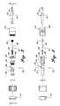
- FIG. 1is a perspective view of a connector for a power tool formed in accordance with one embodiment of the present invention
- FIG. 2is an exploded view of a connector for a power tool formed in accordance with one embodiment of the present invention
- FIG. 3is a side exploded view of a connector for a power tool formed in accordance with one embodiment of the present invention
- FIG. 4is a cross-sectional view of the connector of FIG. 3 taken substantially through Section A—A;
- FIG. 5is a perspective view of an alternate shaft for a connector formed in accordance with the present invention.
- FIG. 6is a side planar view of the alternate shaft of FIG. 5;
- FIG. 7is an end planar view of the alternate shaft of FIG. 6 taken substantially through Section 7 — 7 ;
- FIG. 8is an end planar view of the alternate shaft of FIG. 6 taken substantially through Section 8 — 8 ;
- FIG. 9is a cross-sectional side planar view of the alternate shaft of FIG. 6.
- FIG. 10is a cross-sectional side planar view of a connector formed in accordance with one embodiment of the present invention showing attachment of an optional workpiece attachment.
- FIGS. 1-4illustrate a connector 20 formed in accordance with one embodiment of the present invention.
- the connector 20is adapted to selectively attach a workpiece 22 to a power tool (not shown).
- a power toolnot shown.
- the workpiece 22is illustrated as a Phillips head screwdriver, other workpieces, such as a standard screwdriver and a drill bit, are also within the scope of the present invention.
- the connector 20includes a first collar 24 , a spring biased ball pin assembly 26 , a shaft assembly 28 , and a second collar 30 .
- the workpiece 22is suitably formed from a high strength material and includes a cylindrical drive portion of the hex stem 32 and an appropriate shaped head portion 34 .
- the drive portion of the hex stem 32is sized to be slidably received within the shaft assembly 28 and is seated therein on a spring biased ball pin assembly 26 .
- the spring biased ball pin assembly 26includes a coil spring 36 , a ball pin 38 , and a plug 40 .
- the spring biased ball pin assembly 26is biased to selectively eject the workpiece 22 from within the connector 20 , as is described in greater detail below.
- the shaft assembly 28includes a shaft 42 , collar springs 44 , a ball spring 46 , and centering balls 48 .
- One end of the shaft 42is adapted to be received within a corresponding chuck of a well known power tool.
- the other end of the shaft 42includes a cavity 50 adapted to lockingly receive the hex stem 32 of the workpiece 22 .
- Three of the centering balls 48are disposed around the shaft 42 and are received within corresponding tapered cavities 52 . The centering balls 48 are restrained within the cavities 52 by the ball spring 46 .
- the shaft 42also includes a pair of tapered cavities 54 aligned along a longitudinal axis extending between the open ends of the shaft 42 , such that a forward ball 60 is located near the forward or open end of the shaft 42 .
- a rearward ball 62is located substantially near a midpoint defined along a longitudinal axis extending between the opened and closed ends of the shaft 42 .
- the drive portion of the hex stem 32 of the shaft 42is inserted into the connector 20 , such that the three centering balls 48 near the front lift up and over a lower portion 33 of the hex stem 32 and drop into a power groove 64 .
- the centering balls 48lift up and over the power groove 64 and contact the drive portion of the hex stem 32 .
- the lower portion of the hex stem 32eventually contacts the ball pin 38 at the back of the shaft's cavity 50 .
- the operatorthen continues to press the workpiece 22 into the connector 20 .
- This operationcauses the ball pin 38 , which is tensioned forward by the pin spring 36 to react until the lower portion 33 of the hex stem 32 presses up against the plug 40 .
- the plug 40retains the ball pin 38 and allows clearance for a hex pin 37 found in other optional hex stem configurations, such as the hex pin found in a reversible drill and driver manufactured by Jore Corporation and seen in FIG. 10 .
- the ball pin 38retracts rearwardly to allow the rearward ball 62 to drop into its corresponding tapered hole 54 and flush to the diameter of the shaft 42 . This, in turn, allows the first and second collars 24 and 30 to shift forward because it is tensioned towards the forward position.
- the collarIn translating forward, the collar forces the forward ball 60 to drop into its tapered hole 54 , thereby locking the hex stem 32 at the power groove 64 .
- the collarcontinues forward to contact the three centering balls 48 located at the front of the connector 20 .
- the internal taper 100(FIG. 4) at the front portion of the first collar 24 forces the three centering balls 48 to contact the drive portion of the hex stem 32 and lock it into a centered position. This locking and centering operation takes place by the user simply inserting the workpiece 22 into the connector 20 .
- the order of operationsis basically reversed.
- the operatorpulls the collar back.
- the tensionis removed from the centering balls 48 and the ball locking mechanism, comprised of the forward ball 60 and the forward tapered hole 54 .
- the collarallows space for the rearward ball 62 to move back up out of its hole 54 in the shaft 42 .
- the coil spring 36inside the connector 20 , forces the ball pin 38 forward. This in turn forces the rearward ball 62 up and secures the collar in place.
- the ball pin 38then moves forward, thus moving the workpiece 22 to a position where the three centering balls 48 , which are tensioned radially inward by the ball spring 46 , move off of the drive portion of the hex stem 32 and drop back into the power groove 64 .
- the three tensioned balls 48hold the workpiece 22 at the power groove 64 with a light grip until the operator selectively removes the workpiece 22 from the connector 20 .
- the shaft 142 of the alternate embodimentis identical in materials and operation as the shaft 42 described above with the following exception.
- the aft hole 154has been relocated to a position 180 degrees (based on a longitudinal axis running down the center of the shaft 142 ) from its position shown in the shaft 42 of the first embodiment of FIGS. 1-4.
- all of the ball holesare oriented symmetrically around the shaft's center axis 160 .
- All other connector componentsare also symmetric about the axis 160 when in the assembled position.
- the radial balance of this alternate embodimenthelps to minimize centripetal (centrifugal) forces when the connector is rotating in a power drill. Minimizing the forces that result from rotation results in less vibration. This in turn helps utilize the minimized runout capabilities of the connector. Less runout from the hex stem component (drill, nut driver, power bit, etc.) results in easier use, and greater accuracy from the user's standpoint.
- radial balanceis defined as the center of mass for the assembly as it is aligned with the axis of rotation for the assembly.
Landscapes
- Engineering & Computer Science (AREA)
- Mechanical Engineering (AREA)
- Manipulator (AREA)
- Gripping On Spindles (AREA)
- Manufacturing Of Electrical Connectors (AREA)
Abstract
Description
Claims (20)
Priority Applications (3)
| Application Number | Priority Date | Filing Date | Title |
|---|---|---|---|
| US09/877,717US6722667B2 (en) | 2000-06-09 | 2001-06-08 | Workpiece connector for a power tool |
| US10/703,383US6935637B2 (en) | 2000-06-09 | 2003-11-07 | Workpiece connector for a power tool |
| US10/828,535US20040262856A1 (en) | 2000-06-09 | 2004-04-20 | Workpiece connector for a power tool |
Applications Claiming Priority (2)
| Application Number | Priority Date | Filing Date | Title |
|---|---|---|---|
| US21063100P | 2000-06-09 | 2000-06-09 | |
| US09/877,717US6722667B2 (en) | 2000-06-09 | 2001-06-08 | Workpiece connector for a power tool |
Related Child Applications (2)
| Application Number | Title | Priority Date | Filing Date |
|---|---|---|---|
| US10/703,383ContinuationUS6935637B2 (en) | 2000-06-09 | 2003-11-07 | Workpiece connector for a power tool |
| US10/828,535ContinuationUS20040262856A1 (en) | 2000-06-09 | 2004-04-20 | Workpiece connector for a power tool |
Publications (2)
| Publication Number | Publication Date |
|---|---|
| US20020020973A1 US20020020973A1 (en) | 2002-02-21 |
| US6722667B2true US6722667B2 (en) | 2004-04-20 |
Family
ID=22783641
Family Applications (3)
| Application Number | Title | Priority Date | Filing Date |
|---|---|---|---|
| US09/877,717Expired - LifetimeUS6722667B2 (en) | 2000-06-09 | 2001-06-08 | Workpiece connector for a power tool |
| US10/703,383Expired - Fee RelatedUS6935637B2 (en) | 2000-06-09 | 2003-11-07 | Workpiece connector for a power tool |
| US10/828,535AbandonedUS20040262856A1 (en) | 2000-06-09 | 2004-04-20 | Workpiece connector for a power tool |
Family Applications After (2)
| Application Number | Title | Priority Date | Filing Date |
|---|---|---|---|
| US10/703,383Expired - Fee RelatedUS6935637B2 (en) | 2000-06-09 | 2003-11-07 | Workpiece connector for a power tool |
| US10/828,535AbandonedUS20040262856A1 (en) | 2000-06-09 | 2004-04-20 | Workpiece connector for a power tool |
Country Status (5)
| Country | Link |
|---|---|
| US (3) | US6722667B2 (en) |
| EP (1) | EP1294514A4 (en) |
| AU (1) | AU2001266789A1 (en) |
| CA (1) | CA2411405C (en) |
| WO (1) | WO2001096052A1 (en) |
Cited By (69)
| Publication number | Priority date | Publication date | Assignee | Title |
|---|---|---|---|---|
| US20030230862A1 (en)* | 2002-06-18 | 2003-12-18 | Peters Michael P. | Bit holder |
| US20040164503A1 (en)* | 2003-02-21 | 2004-08-26 | Wei-Chuan Fan-Chiang | Bit quick-release device |
| US20040173061A1 (en)* | 2002-10-16 | 2004-09-09 | Mou-Tang Liou | Tool including bit and handle |
| US20040220554A1 (en)* | 2000-06-24 | 2004-11-04 | Andre Lechot | Hand-held instrument holder for surgical use |
| US20050066779A1 (en)* | 2003-09-30 | 2005-03-31 | Chin-Tan Huang | Screwdriver |
| US20050176283A1 (en)* | 2003-12-11 | 2005-08-11 | Jore Corporation | Screwdriver connector |
| WO2005089989A1 (en)* | 2004-03-15 | 2005-09-29 | Wienhold James L | Dual size tool-bit holder |
| US20050260052A1 (en)* | 2002-03-25 | 2005-11-24 | Lovchik Christopher S | Quick change adaptor for rotary machines |
| US20050284270A1 (en)* | 2004-06-28 | 2005-12-29 | Huang Ping W | Screwdriver fast connector |
| US20060137495A1 (en)* | 2004-12-29 | 2006-06-29 | Ting Hwang | Sectionless length adjustment mechanism for tool shank |
| US20060181033A1 (en)* | 2005-02-14 | 2006-08-17 | Ho-Tien Chen | Bit holder |
| US20060186615A1 (en)* | 2005-02-18 | 2006-08-24 | Gibbons Louis A | Drill chuck tool bit locator |
| US20060228181A1 (en)* | 2005-04-08 | 2006-10-12 | Kozak Ira M | Fast change bit holder device |
| US20070025028A1 (en)* | 2005-07-29 | 2007-02-01 | Chung Young S | Tunnel junction sensor with magnetic cladding |
| US20070034060A1 (en)* | 2005-08-15 | 2007-02-15 | Eastway Fair Company Limited | Screw guide device |
| US20070108706A1 (en)* | 2005-02-25 | 2007-05-17 | Jore Corporation | Tool connector having multiple locking positions |
| US20070152408A1 (en)* | 2005-12-29 | 2007-07-05 | Black & Decker Inc. | Universal tool bit shank |
| US20070171540A1 (en)* | 2006-01-19 | 2007-07-26 | Sdgi Holdings, Inc. | Devices and methods for grasping an elongated medical element |
| US20070228672A1 (en)* | 2006-04-04 | 2007-10-04 | Huang Ping W | Multi-size fast connector |
| US7284936B1 (en)* | 2004-04-26 | 2007-10-23 | Teleflex Medical Incorporated | Tool bit and collet assembly and method |
| USD563750S1 (en) | 2005-12-29 | 2008-03-11 | Black & Decker Inc. | Universal shank for tools |
| US20080111323A1 (en)* | 2006-11-09 | 2008-05-15 | Westport Medical, Inc. | Bit holders |
| US20080121075A1 (en)* | 2006-11-23 | 2008-05-29 | Meng Chi-Fen | Device for locking and releasing a scrwe bit |
| USD575609S1 (en) | 2005-12-29 | 2008-08-26 | Black & Decker Inc. | Universal shank for tools |
| USD575808S1 (en) | 2007-03-02 | 2008-08-26 | Milwaukee Electric Tool Corporation | Cutting tool |
| US20080217870A1 (en)* | 2007-03-07 | 2008-09-11 | Makita Corporation | Bit mounting devices |
| US7469753B2 (en) | 2005-06-01 | 2008-12-30 | Milwaukee Electric Tool Corporation | Power tool, drive assembly, and method of operating the same |
| US20090033042A1 (en)* | 2006-08-08 | 2009-02-05 | Rinner James A | Tool Chuck |
| US7581470B1 (en)* | 2008-11-25 | 2009-09-01 | Jui-Min Huang | Universal screwdriver bit set |
| US20090224492A1 (en)* | 2008-03-10 | 2009-09-10 | Jack Lin | Bit connector with quick release device |
| US7625160B2 (en) | 2006-03-02 | 2009-12-01 | Milwaukee Electric Tool Corporation | Cutting tool |
| USD605672S1 (en) | 2007-03-01 | 2009-12-08 | Milwaukee Electric Tool Corporation | Cutting blade |
| US7740249B1 (en) | 2006-05-01 | 2010-06-22 | Bradshaw Medical, Inc. | Holder for replaceable tools |
| US20100225073A1 (en)* | 2006-11-09 | 2010-09-09 | Douglas Roy Porter | Bit holders |
| US7810817B1 (en) | 2006-11-20 | 2010-10-12 | Bradshaw Medical, Inc. | Holder for replaceable tools |
| US20100260537A1 (en)* | 2009-04-09 | 2010-10-14 | Hong Fu Jin Precision Industry (Shenzhen) Co., Ltd | Connecting structure for swivel shafts |
| US20100282485A1 (en)* | 2009-05-05 | 2010-11-11 | Black & Decker Inc. | Power tool with integrated bit retention device |
| US20120058446A1 (en)* | 2009-03-26 | 2012-03-08 | Hannes Wagner | Chucking device for a medical or dental handpiece |
| US8328477B2 (en) | 2006-03-02 | 2012-12-11 | Milwaukee Electric Tool Corporation | Cutting tool |
| US20130001897A1 (en)* | 2011-06-30 | 2013-01-03 | Chen Bo-Shen | Connecting rod assembly for connecting a work head |
| US8607673B2 (en) | 2011-02-14 | 2013-12-17 | James B. Marson | Tool modification to prevent inadvertent release of tool attachments |
| US8622401B2 (en) | 2009-02-27 | 2014-01-07 | Black & Decker Inc. | Bit retention device |
| US20140165794A1 (en)* | 2012-12-18 | 2014-06-19 | Wen Hung Chiang | Fastener holder for power tool |
| US8800999B2 (en) | 2009-02-27 | 2014-08-12 | Black & Decker Inc. | Bit retention device |
| US20140239599A1 (en)* | 2011-06-16 | 2014-08-28 | Von Arx Ag | Quick coupling system for fastening an interchangeable head on a press tool |
| US8985593B1 (en)* | 2011-07-14 | 2015-03-24 | Bradshaw Medical, Inc. | Self-locking internal adapter for D-shaped orthopedic adjustment tools |
| US20150143966A1 (en)* | 2013-06-12 | 2015-05-28 | Andrew Arlin Pischke | Locking Quick Release Protective Cap Assembly For Pocket Tools |
| US20150202689A1 (en)* | 2014-01-22 | 2015-07-23 | Good Year Hardware Co., Ltd. | Tool bit adapter having a position-limit rod |
| US9156147B2 (en) | 2012-02-15 | 2015-10-13 | Black & Decker Inc. | Quick change bit holder with ring magnet |
| US9227309B2 (en) | 2012-02-15 | 2016-01-05 | Black & Decker Inc. | Quick change bit holder with ring magnet |
| US20160107299A1 (en)* | 2014-10-17 | 2016-04-21 | Chung Taan Industrial Co., Ltd | Connector |
| US9500038B2 (en) | 2013-02-01 | 2016-11-22 | Milwaukee Electric Tool Corporation | Auger bit with replaceable cutting bit |
| US9505108B2 (en) | 2012-02-15 | 2016-11-29 | Black & Decker Inc. | Bit holder with floating magnet sleeve |
| USD780548S1 (en) | 2015-07-22 | 2017-03-07 | Ac (Macao Commercial Offshore) Limited | Power tool |
| USD789761S1 (en) | 2015-11-02 | 2017-06-20 | Black & Decker Inc. | Torsion bit |
| US20170333999A1 (en)* | 2016-05-19 | 2017-11-23 | Ac (Macao Commercial Offshore) Limited | Tool bit holder |
| USD806493S1 (en) | 2015-07-22 | 2018-01-02 | Tti (Macao Commercial Offshore) Limited | Tool adapter |
| US9873155B1 (en) | 2009-04-22 | 2018-01-23 | Insty-Bit, Llc | Quick change tool bit holder for round shafts |
| US9943946B2 (en) | 2012-02-15 | 2018-04-17 | Black & Decker Inc. | Tool bits with floating magnet sleeves |
| US20180126523A1 (en)* | 2016-11-07 | 2018-05-10 | Jacques Rajotte | Screw driving device for use with an impact driver |
| US10150205B2 (en) | 2012-02-15 | 2018-12-11 | Black & Decker Inc. | Fastening tools with floating magnet sleeves |
| US20190358712A1 (en)* | 2018-05-28 | 2019-11-28 | Karl Storz Se & Co. Kg | Self-Securing Coupling Device And Method |
| US10569343B2 (en)* | 2017-11-06 | 2020-02-25 | Ingersoll-Rand Company | Quick locking and releasing attachment retainer |
| USD877590S1 (en) | 2018-07-20 | 2020-03-10 | Milwaukee Electric Tool Corporation | Tool accessory |
| USD906081S1 (en)* | 2018-08-20 | 2020-12-29 | Milwaukee Electric Tool Corporation | Driver bit |
| US11065744B2 (en) | 2018-07-20 | 2021-07-20 | Milwaukee Electric Tool Corporation | Tool bit holder |
| US11317899B2 (en)* | 2019-10-14 | 2022-05-03 | Terumo Cardiovascular Systems Corporation | Ball-to-shaft quick connect adapter for surgical retraction tools |
| US11342101B2 (en) | 2018-07-20 | 2022-05-24 | Milwaukee Electric Tool Corporation | Magnetism booster assembly |
| US11413729B2 (en) | 2018-08-20 | 2022-08-16 | Milwaukee Electric Tool Corporation | Tool bit |
Families Citing this family (27)
| Publication number | Priority date | Publication date | Assignee | Title |
|---|---|---|---|---|
| US6457916B2 (en)* | 1999-11-15 | 2002-10-01 | Insty-Bit, Inc. | Locking quick-change chuck assembly |
| US6637755B2 (en)* | 2002-03-22 | 2003-10-28 | Tsai-Ching Chen | Chuck device for miniature tool bits |
| AU2003240620A1 (en)* | 2002-06-10 | 2003-12-22 | Wera Werk | Chuck for receiving tools operated by rotating around the axis thereof |
| DE10254339B4 (en) | 2002-06-10 | 2019-10-10 | Wera Werkzeuge Gmbh | Lining for holding tools that can be turned around their axis |
| US8132990B2 (en) | 2003-12-23 | 2012-03-13 | Lynn Everett Bauman | Bit holding apparatus for use with a power tool |
| US7354230B2 (en) | 2003-12-23 | 2008-04-08 | Lynn Bauman | Bit holding apparatus for use with a power tool |
| US20060027057A1 (en)* | 2004-08-04 | 2006-02-09 | Chih-Ching Hsien | Quick release device for releasing screw bit from socket |
| US7195247B2 (en)* | 2005-01-25 | 2007-03-27 | Zu-Shung Shu | Tool joint |
| US7306238B2 (en)* | 2005-03-01 | 2007-12-11 | Kennametal Inc. | Collet and lock nut |
| CH704836B1 (en)* | 2006-03-02 | 2012-10-31 | Bd Werkzeugtechnik Ag | Quick-change holder for screwdriver bits. |
| USD556527S1 (en) | 2006-04-19 | 2007-12-04 | Fiskars Brands, Inc. | Jewelry drill |
| US20070290458A1 (en)* | 2006-06-15 | 2007-12-20 | Shun-Yuan Chuang | Replaceable adapter for an electric hand tool |
| US8506459B2 (en)* | 2006-08-01 | 2013-08-13 | Torque Fitness, Llc | Freestanding exercise apparatus |
| MY144060A (en)* | 2006-12-14 | 2011-08-15 | Erowa Ag | Work piece carrier for exactly positioning a work piece on a chuck and clamping apparatus with a chuck and a work piece carrier |
| DE102007005033A1 (en)* | 2007-02-01 | 2008-08-07 | Robert Bosch Gmbh | Tool holder for a machine tool, in particular for a hand tool |
| US8262098B2 (en)* | 2008-02-05 | 2012-09-11 | Robert Bosch Gmbh | Rotary tool system with centering member |
| US20100186559A1 (en)* | 2009-01-24 | 2010-07-29 | Kun-Chen Chen | Multi-use, interchangeable tool |
| US20100229693A1 (en)* | 2009-03-11 | 2010-09-16 | Kun-Chen Chen | Detachable screwdriver assembly |
| US8262097B2 (en)* | 2009-07-07 | 2012-09-11 | Jin-Tsai Lai | Quick-release mechanism for hand tool |
| CN102107287B (en)* | 2009-12-29 | 2012-12-12 | 苏州宝时得电动工具有限公司 | Chuck and electric tool using same |
| CN101823249A (en)* | 2010-03-24 | 2010-09-08 | 无锡市新菊电动工具有限公司 | Quick chuck of screwdriver |
| US8292150B2 (en) | 2010-11-02 | 2012-10-23 | Tyco Healthcare Group Lp | Adapter for powered surgical devices |
| TWI362312B (en)* | 2011-04-19 | 2012-04-21 | Chung Taan Ind Co Ltd | Connecting rod |
| US20130186244A1 (en)* | 2012-01-19 | 2013-07-25 | Jack Lin | Chuck |
| DE102013103937B4 (en)* | 2013-04-18 | 2014-12-04 | Bilz Werkzeugfabrik Gmbh & Co. Kg | Quick change system for a tool holder |
| TWI556922B (en)* | 2014-01-22 | 2016-11-11 | Good Year Hardware Co Ltd | Tool head structure |
| USD1004386S1 (en)* | 2021-10-12 | 2023-11-14 | Untwisted Tech LLC | Untwist tool |
Citations (17)
| Publication number | Priority date | Publication date | Assignee | Title |
|---|---|---|---|---|
| US2348611A (en)* | 1942-06-12 | 1944-05-09 | Davidson Cecil Stanley | Clamp for holding drill rods or casings |
| US2751229A (en)* | 1953-11-16 | 1956-06-19 | Arthur B Schultz | Releasable gripper for holding an article suspended |
| US3521895A (en)* | 1968-07-24 | 1970-07-28 | Theodore M Smith | Tool holder |
| US4577875A (en) | 1982-10-29 | 1986-03-25 | Miyakawa Industry Co., Ltd. | Exchange chuck for a tool |
| US4629375A (en)* | 1983-08-24 | 1986-12-16 | Wera Werk Hermann Werner Gmbh & Co. | Chuck for tool shanks, particularly screwdriver bits |
| US4692073A (en)* | 1985-02-25 | 1987-09-08 | Martindell J Richard | Handle adapter and chuck apparatus for power bits |
| US4850758A (en)* | 1988-11-15 | 1989-07-25 | Morgan William W | Quick-change drill bits and holder |
| US5013194A (en)* | 1988-09-08 | 1991-05-07 | Wienhold James L | Chuck assembly for tool bits |
| US5062749A (en) | 1989-02-21 | 1991-11-05 | Sheets Harold D | Tool coupler |
| US5398946A (en)* | 1993-12-29 | 1995-03-21 | Poly-Tech Industries | Chuck having one-step lock and release |
| US5417527A (en)* | 1994-08-12 | 1995-05-23 | Wienhold; James L. | Quick change chuck assembly for tool bits |
| US5934384A (en)* | 1998-04-27 | 1999-08-10 | Wang; Peter | Transmission shaft and bit mounting arrangement of a motor-driven hand drill |
| US6126370A (en)* | 1998-07-22 | 2000-10-03 | Black & Decker Inc. | Removable tool holder |
| US6199872B1 (en) | 1999-08-13 | 2001-03-13 | Maxtech Consumer Products, L.L.C. | Quick-release mechanism for screwdriver bits and the like |
| US6270085B1 (en) | 1999-10-01 | 2001-08-07 | Tsai-Ching Chen | Chuck device for tool bits |
| US6325393B1 (en)* | 1999-10-01 | 2001-12-04 | Tsai-Ching Chen | Chuck device for tools |
| US6457916B2 (en)* | 1999-11-15 | 2002-10-01 | Insty-Bit, Inc. | Locking quick-change chuck assembly |
Family Cites Families (18)
| Publication number | Priority date | Publication date | Assignee | Title |
|---|---|---|---|---|
| US2481945A (en)* | 1944-10-30 | 1949-09-13 | Springfield Detail & Machine P | Toolholding chuck |
| US3023015A (en)* | 1960-01-05 | 1962-02-27 | Melvin W Pankow | Reversible bit drill attachment |
| US3251605A (en)* | 1963-09-26 | 1966-05-17 | Supreme Products Corp | Quick release chuck |
| US3436086A (en)* | 1966-05-31 | 1969-04-01 | Hanson Whitney Co The | Tool holder |
| US3788658A (en)* | 1972-08-14 | 1974-01-29 | Erickson Tool Co | Instant change tool holder |
| US3767218A (en)* | 1973-02-21 | 1973-10-23 | Carrier Corp | Tool chuck |
| US3975032A (en)* | 1974-04-15 | 1976-08-17 | Minnesota Mining And Manufacturing Company | Surgical wire driving assembly |
| DE3624232A1 (en)* | 1986-07-18 | 1988-01-28 | Hilti Ag | CHUCK FOR TOOLS |
| US5222956A (en)* | 1992-07-06 | 1993-06-29 | Altair Instruments, Inc. | Surgical drill collet mechanism and bur |
| DE4343013C2 (en)* | 1993-12-16 | 2003-04-03 | Bosch Gmbh Robert | Hammer drill with a combination tool holder |
| US5678961A (en)* | 1995-05-11 | 1997-10-21 | Fleege; Dennis W. | Quick change adapter |
| US6053675A (en)* | 1998-06-26 | 2000-04-25 | Black & Decker Inc. | Quick-acting tool bit holder |
| JP3359288B2 (en)* | 1998-06-30 | 2002-12-24 | 政人 石井 | Chuck |
| US5996452A (en)* | 1998-10-13 | 1999-12-07 | Chiang; Shu Chi | Chuck device for power tool |
| US6488452B1 (en)* | 1999-08-12 | 2002-12-03 | Vermont American Corporation | Drill and drive apparatus having arrangement to accommodate long drill bits |
| US6688610B2 (en)* | 2000-05-12 | 2004-02-10 | Power Tool Holders Incorporated | Chuck with quick change |
| EP1193014B1 (en)* | 2000-09-01 | 2004-07-07 | Credo Technology Corporation | Mandrel assembly for hole saw and drill bit |
| US6533291B2 (en)* | 2001-02-14 | 2003-03-18 | Power Tool Holders Incorporated | Chuck having quick change mechanism |
- 2001
- 2001-06-08WOPCT/US2001/018572patent/WO2001096052A1/enactiveApplication Filing
- 2001-06-08AUAU2001266789Apatent/AU2001266789A1/ennot_activeAbandoned
- 2001-06-08USUS09/877,717patent/US6722667B2/ennot_activeExpired - Lifetime
- 2001-06-08EPEP01944369Apatent/EP1294514A4/ennot_activeWithdrawn
- 2001-06-08CACA002411405Apatent/CA2411405C/ennot_activeExpired - Fee Related
- 2003
- 2003-11-07USUS10/703,383patent/US6935637B2/ennot_activeExpired - Fee Related
- 2004
- 2004-04-20USUS10/828,535patent/US20040262856A1/ennot_activeAbandoned
Patent Citations (17)
| Publication number | Priority date | Publication date | Assignee | Title |
|---|---|---|---|---|
| US2348611A (en)* | 1942-06-12 | 1944-05-09 | Davidson Cecil Stanley | Clamp for holding drill rods or casings |
| US2751229A (en)* | 1953-11-16 | 1956-06-19 | Arthur B Schultz | Releasable gripper for holding an article suspended |
| US3521895A (en)* | 1968-07-24 | 1970-07-28 | Theodore M Smith | Tool holder |
| US4577875A (en) | 1982-10-29 | 1986-03-25 | Miyakawa Industry Co., Ltd. | Exchange chuck for a tool |
| US4629375A (en)* | 1983-08-24 | 1986-12-16 | Wera Werk Hermann Werner Gmbh & Co. | Chuck for tool shanks, particularly screwdriver bits |
| US4692073A (en)* | 1985-02-25 | 1987-09-08 | Martindell J Richard | Handle adapter and chuck apparatus for power bits |
| US5013194A (en)* | 1988-09-08 | 1991-05-07 | Wienhold James L | Chuck assembly for tool bits |
| US4850758A (en)* | 1988-11-15 | 1989-07-25 | Morgan William W | Quick-change drill bits and holder |
| US5062749A (en) | 1989-02-21 | 1991-11-05 | Sheets Harold D | Tool coupler |
| US5398946A (en)* | 1993-12-29 | 1995-03-21 | Poly-Tech Industries | Chuck having one-step lock and release |
| US5417527A (en)* | 1994-08-12 | 1995-05-23 | Wienhold; James L. | Quick change chuck assembly for tool bits |
| US5934384A (en)* | 1998-04-27 | 1999-08-10 | Wang; Peter | Transmission shaft and bit mounting arrangement of a motor-driven hand drill |
| US6126370A (en)* | 1998-07-22 | 2000-10-03 | Black & Decker Inc. | Removable tool holder |
| US6199872B1 (en) | 1999-08-13 | 2001-03-13 | Maxtech Consumer Products, L.L.C. | Quick-release mechanism for screwdriver bits and the like |
| US6270085B1 (en) | 1999-10-01 | 2001-08-07 | Tsai-Ching Chen | Chuck device for tool bits |
| US6325393B1 (en)* | 1999-10-01 | 2001-12-04 | Tsai-Ching Chen | Chuck device for tools |
| US6457916B2 (en)* | 1999-11-15 | 2002-10-01 | Insty-Bit, Inc. | Locking quick-change chuck assembly |
Cited By (116)
| Publication number | Priority date | Publication date | Assignee | Title |
|---|---|---|---|---|
| US20040220554A1 (en)* | 2000-06-24 | 2004-11-04 | Andre Lechot | Hand-held instrument holder for surgical use |
| US7296804B2 (en)* | 2000-06-24 | 2007-11-20 | Precimed S.A. | Hand-held instrument holder for surgical use |
| US20050260052A1 (en)* | 2002-03-25 | 2005-11-24 | Lovchik Christopher S | Quick change adaptor for rotary machines |
| US6929266B2 (en)* | 2002-06-18 | 2005-08-16 | Black & Decker Inc. | Bit holder |
| US20030230862A1 (en)* | 2002-06-18 | 2003-12-18 | Peters Michael P. | Bit holder |
| US20040173061A1 (en)* | 2002-10-16 | 2004-09-09 | Mou-Tang Liou | Tool including bit and handle |
| US7036404B2 (en)* | 2002-10-16 | 2006-05-02 | Mou-Tang Liou | Tool including bit and handle |
| US20040164503A1 (en)* | 2003-02-21 | 2004-08-26 | Wei-Chuan Fan-Chiang | Bit quick-release device |
| US20050066779A1 (en)* | 2003-09-30 | 2005-03-31 | Chin-Tan Huang | Screwdriver |
| US6901826B2 (en)* | 2003-09-30 | 2005-06-07 | Chin-Tan Huang | Screwdriver |
| US20050176283A1 (en)* | 2003-12-11 | 2005-08-11 | Jore Corporation | Screwdriver connector |
| US7086313B2 (en)* | 2003-12-11 | 2006-08-08 | Jore Corporation | Screwdriver connector |
| WO2005060551A3 (en)* | 2003-12-11 | 2006-06-22 | Jore Corp | Screwdriver connector |
| US20080246233A1 (en)* | 2004-03-15 | 2008-10-09 | Wienhold James L | Dual Size Tool-Bit Holder |
| US7896355B2 (en) | 2004-03-15 | 2011-03-01 | Wienhold James L | Dual size tool-bit holder |
| US20110140376A1 (en)* | 2004-03-15 | 2011-06-16 | Wienhold James L | Dual Size Tool-Bit Holder |
| US8844940B2 (en) | 2004-03-15 | 2014-09-30 | Insty-Bit, Llc | Dual Size tool-bit holder |
| WO2005089989A1 (en)* | 2004-03-15 | 2005-09-29 | Wienhold James L | Dual size tool-bit holder |
| US8292304B2 (en) | 2004-03-15 | 2012-10-23 | Insty-Bit, Llc | Dual size tool-bit holder |
| US7284936B1 (en)* | 2004-04-26 | 2007-10-23 | Teleflex Medical Incorporated | Tool bit and collet assembly and method |
| US20050284270A1 (en)* | 2004-06-28 | 2005-12-29 | Huang Ping W | Screwdriver fast connector |
| US7111530B2 (en)* | 2004-06-28 | 2006-09-26 | Ping Wen Huang | Screwdriver fast connector |
| US20060137495A1 (en)* | 2004-12-29 | 2006-06-29 | Ting Hwang | Sectionless length adjustment mechanism for tool shank |
| US7146885B2 (en)* | 2004-12-29 | 2006-12-12 | Ting Hwang | Sectionless length adjustment mechanism for tool shank |
| US7175185B2 (en)* | 2005-02-14 | 2007-02-13 | Ho-Tien Chen | Bit holder |
| US20060181033A1 (en)* | 2005-02-14 | 2006-08-17 | Ho-Tien Chen | Bit holder |
| US7243922B2 (en)* | 2005-02-18 | 2007-07-17 | Black & Decker Inc. | Drill chuck tool bit locator |
| US20060186615A1 (en)* | 2005-02-18 | 2006-08-24 | Gibbons Louis A | Drill chuck tool bit locator |
| US20070108706A1 (en)* | 2005-02-25 | 2007-05-17 | Jore Corporation | Tool connector having multiple locking positions |
| US7334970B2 (en) | 2005-04-08 | 2008-02-26 | Eazypower Corporation | Fast change bit holder device |
| US20060228181A1 (en)* | 2005-04-08 | 2006-10-12 | Kozak Ira M | Fast change bit holder device |
| US7469753B2 (en) | 2005-06-01 | 2008-12-30 | Milwaukee Electric Tool Corporation | Power tool, drive assembly, and method of operating the same |
| US7658239B2 (en) | 2005-06-01 | 2010-02-09 | Milwaukee Electric Tool Corporation | Power tool, drive assembly, and method of operating the same |
| US20070025028A1 (en)* | 2005-07-29 | 2007-02-01 | Chung Young S | Tunnel junction sensor with magnetic cladding |
| US20070034060A1 (en)* | 2005-08-15 | 2007-02-15 | Eastway Fair Company Limited | Screw guide device |
| US7210382B2 (en) | 2005-08-15 | 2007-05-01 | Eastway Fair Company Ltd. | Screw guide device |
| USD563750S1 (en) | 2005-12-29 | 2008-03-11 | Black & Decker Inc. | Universal shank for tools |
| US7896357B2 (en) | 2005-12-29 | 2011-03-01 | Black & Decker Inc. | Universal tool bit shank |
| USD575609S1 (en) | 2005-12-29 | 2008-08-26 | Black & Decker Inc. | Universal shank for tools |
| US20070152408A1 (en)* | 2005-12-29 | 2007-07-05 | Black & Decker Inc. | Universal tool bit shank |
| US20100133762A1 (en)* | 2005-12-29 | 2010-06-03 | Black & Decker Inc. | Universal Tool Bit Shank |
| US7726664B2 (en) | 2005-12-29 | 2010-06-01 | Black & Decker Inc. | Universal tool bit shank |
| US8016830B2 (en)* | 2006-01-19 | 2011-09-13 | Warsaw Orthopedic, Inc. | Devices and methods for grasping an elongated medical element |
| US20070171540A1 (en)* | 2006-01-19 | 2007-07-26 | Sdgi Holdings, Inc. | Devices and methods for grasping an elongated medical element |
| US10618119B2 (en) | 2006-03-02 | 2020-04-14 | Milwaukee Electric Tool Corporation | Cutting tool |
| US8371777B2 (en) | 2006-03-02 | 2013-02-12 | Milwaukee Electric Tool Corporation | Cutting tool |
| US7661911B2 (en) | 2006-03-02 | 2010-02-16 | Milwaukee Electric Tool Corporation | Cutting tool |
| US7625160B2 (en) | 2006-03-02 | 2009-12-01 | Milwaukee Electric Tool Corporation | Cutting tool |
| US8328477B2 (en) | 2006-03-02 | 2012-12-11 | Milwaukee Electric Tool Corporation | Cutting tool |
| US9339874B2 (en) | 2006-03-02 | 2016-05-17 | Milwaukee Electric Tool Corporation | Cutting tool |
| US20070228672A1 (en)* | 2006-04-04 | 2007-10-04 | Huang Ping W | Multi-size fast connector |
| US7740249B1 (en) | 2006-05-01 | 2010-06-22 | Bradshaw Medical, Inc. | Holder for replaceable tools |
| US20090033042A1 (en)* | 2006-08-08 | 2009-02-05 | Rinner James A | Tool Chuck |
| US20100225073A1 (en)* | 2006-11-09 | 2010-09-09 | Douglas Roy Porter | Bit holders |
| US20080111323A1 (en)* | 2006-11-09 | 2008-05-15 | Westport Medical, Inc. | Bit holders |
| US8882113B2 (en) | 2006-11-09 | 2014-11-11 | Westport Medical, Inc. | Bit holders |
| US7810817B1 (en) | 2006-11-20 | 2010-10-12 | Bradshaw Medical, Inc. | Holder for replaceable tools |
| US7922180B2 (en)* | 2006-11-23 | 2011-04-12 | Chi-Fen Meng | Device for locking and releasing a screw bit |
| US20080121075A1 (en)* | 2006-11-23 | 2008-05-29 | Meng Chi-Fen | Device for locking and releasing a scrwe bit |
| USD605672S1 (en) | 2007-03-01 | 2009-12-08 | Milwaukee Electric Tool Corporation | Cutting blade |
| USD575808S1 (en) | 2007-03-02 | 2008-08-26 | Milwaukee Electric Tool Corporation | Cutting tool |
| US8172236B2 (en)* | 2007-03-07 | 2012-05-08 | Makita Corporation | Bit mounting devices |
| US20080217870A1 (en)* | 2007-03-07 | 2008-09-11 | Makita Corporation | Bit mounting devices |
| US20090224492A1 (en)* | 2008-03-10 | 2009-09-10 | Jack Lin | Bit connector with quick release device |
| US7581470B1 (en)* | 2008-11-25 | 2009-09-01 | Jui-Min Huang | Universal screwdriver bit set |
| US9067266B2 (en)* | 2009-02-27 | 2015-06-30 | Black & Decker Inc. | Bit retention device |
| US8622401B2 (en) | 2009-02-27 | 2014-01-07 | Black & Decker Inc. | Bit retention device |
| US8800999B2 (en) | 2009-02-27 | 2014-08-12 | Black & Decker Inc. | Bit retention device |
| US20140312578A1 (en)* | 2009-02-27 | 2014-10-23 | Black & Decker Inc. | Bit retention device |
| US8870570B2 (en)* | 2009-03-26 | 2014-10-28 | W&H Dentalwerk Bürmoos GmbH | Chucking device for a medical or dental handpiece |
| US20120058446A1 (en)* | 2009-03-26 | 2012-03-08 | Hannes Wagner | Chucking device for a medical or dental handpiece |
| US20100260537A1 (en)* | 2009-04-09 | 2010-10-14 | Hong Fu Jin Precision Industry (Shenzhen) Co., Ltd | Connecting structure for swivel shafts |
| US9873155B1 (en) | 2009-04-22 | 2018-01-23 | Insty-Bit, Llc | Quick change tool bit holder for round shafts |
| US8381830B2 (en) | 2009-05-05 | 2013-02-26 | Black & Decker Inc. | Power tool with integrated bit retention device |
| US20100282485A1 (en)* | 2009-05-05 | 2010-11-11 | Black & Decker Inc. | Power tool with integrated bit retention device |
| US8607673B2 (en) | 2011-02-14 | 2013-12-17 | James B. Marson | Tool modification to prevent inadvertent release of tool attachments |
| US20140239599A1 (en)* | 2011-06-16 | 2014-08-28 | Von Arx Ag | Quick coupling system for fastening an interchangeable head on a press tool |
| US9573335B2 (en)* | 2011-06-16 | 2017-02-21 | Von Arx Ag | Quick coupling system for fastening an interchangeable head on a press tool |
| US8876120B2 (en)* | 2011-06-30 | 2014-11-04 | Bo-Shen CHEN | Connecting rod assembly for connecting a work head |
| US20130001897A1 (en)* | 2011-06-30 | 2013-01-03 | Chen Bo-Shen | Connecting rod assembly for connecting a work head |
| US8985593B1 (en)* | 2011-07-14 | 2015-03-24 | Bradshaw Medical, Inc. | Self-locking internal adapter for D-shaped orthopedic adjustment tools |
| US10150205B2 (en) | 2012-02-15 | 2018-12-11 | Black & Decker Inc. | Fastening tools with floating magnet sleeves |
| US10556329B2 (en) | 2012-02-15 | 2020-02-11 | Black & Decker Inc. | Tool bits with floating magnet sleeves |
| US9943946B2 (en) | 2012-02-15 | 2018-04-17 | Black & Decker Inc. | Tool bits with floating magnet sleeves |
| US9156147B2 (en) | 2012-02-15 | 2015-10-13 | Black & Decker Inc. | Quick change bit holder with ring magnet |
| US10040179B2 (en) | 2012-02-15 | 2018-08-07 | Black & Decker Inc. | Fastener tool assemblies |
| US9505108B2 (en) | 2012-02-15 | 2016-11-29 | Black & Decker Inc. | Bit holder with floating magnet sleeve |
| US9227309B2 (en) | 2012-02-15 | 2016-01-05 | Black & Decker Inc. | Quick change bit holder with ring magnet |
| US8943931B2 (en)* | 2012-12-18 | 2015-02-03 | Wen Hung Chiang | Fastener holder for power tool |
| US20140165794A1 (en)* | 2012-12-18 | 2014-06-19 | Wen Hung Chiang | Fastener holder for power tool |
| US9500038B2 (en) | 2013-02-01 | 2016-11-22 | Milwaukee Electric Tool Corporation | Auger bit with replaceable cutting bit |
| US20150143966A1 (en)* | 2013-06-12 | 2015-05-28 | Andrew Arlin Pischke | Locking Quick Release Protective Cap Assembly For Pocket Tools |
| US9381627B2 (en)* | 2014-01-22 | 2016-07-05 | Good Year Hardware Co., Ltd. | Tool bit adapter having a position-limit rod |
| US20150202689A1 (en)* | 2014-01-22 | 2015-07-23 | Good Year Hardware Co., Ltd. | Tool bit adapter having a position-limit rod |
| US9561582B2 (en)* | 2014-10-17 | 2017-02-07 | Chung Taan Industrial Co., Ltd. | Connector |
| US20160107299A1 (en)* | 2014-10-17 | 2016-04-21 | Chung Taan Industrial Co., Ltd | Connector |
| USD780548S1 (en) | 2015-07-22 | 2017-03-07 | Ac (Macao Commercial Offshore) Limited | Power tool |
| USD806493S1 (en) | 2015-07-22 | 2018-01-02 | Tti (Macao Commercial Offshore) Limited | Tool adapter |
| USD789761S1 (en) | 2015-11-02 | 2017-06-20 | Black & Decker Inc. | Torsion bit |
| USD841425S1 (en) | 2015-11-02 | 2019-02-26 | Black & Decker Inc. | Torsion bit |
| US10286456B2 (en)* | 2016-05-19 | 2019-05-14 | Tti (Macao Commerical Offshore) Limited | Tool bit holder |
| US20170333999A1 (en)* | 2016-05-19 | 2017-11-23 | Ac (Macao Commercial Offshore) Limited | Tool bit holder |
| US20180126523A1 (en)* | 2016-11-07 | 2018-05-10 | Jacques Rajotte | Screw driving device for use with an impact driver |
| US10821579B2 (en)* | 2016-11-07 | 2020-11-03 | Jacques Rajotte | Screw driving device for use with an impact driver |
| US10569343B2 (en)* | 2017-11-06 | 2020-02-25 | Ingersoll-Rand Company | Quick locking and releasing attachment retainer |
| US20190358712A1 (en)* | 2018-05-28 | 2019-11-28 | Karl Storz Se & Co. Kg | Self-Securing Coupling Device And Method |
| US10940540B2 (en)* | 2018-05-28 | 2021-03-09 | Karl Storz Se & Co. Kg | Self-securing coupling device and method |
| USD877590S1 (en) | 2018-07-20 | 2020-03-10 | Milwaukee Electric Tool Corporation | Tool accessory |
| US11065744B2 (en) | 2018-07-20 | 2021-07-20 | Milwaukee Electric Tool Corporation | Tool bit holder |
| US11342101B2 (en) | 2018-07-20 | 2022-05-24 | Milwaukee Electric Tool Corporation | Magnetism booster assembly |
| US11783977B2 (en) | 2018-07-20 | 2023-10-10 | Milwaukee Electric Tool Corporation | Magnetism booster assembly |
| USD906081S1 (en)* | 2018-08-20 | 2020-12-29 | Milwaukee Electric Tool Corporation | Driver bit |
| USD933443S1 (en) | 2018-08-20 | 2021-10-19 | Milwaukee Electric Tool Corporation | Driver bit |
| US11413729B2 (en) | 2018-08-20 | 2022-08-16 | Milwaukee Electric Tool Corporation | Tool bit |
| US11883931B2 (en) | 2018-08-20 | 2024-01-30 | Milwaukee Electric Tool Corporation | Tool bit |
| US11317899B2 (en)* | 2019-10-14 | 2022-05-03 | Terumo Cardiovascular Systems Corporation | Ball-to-shaft quick connect adapter for surgical retraction tools |
Also Published As
| Publication number | Publication date |
|---|---|
| US20040262856A1 (en) | 2004-12-30 |
| US20020020973A1 (en) | 2002-02-21 |
| CA2411405A1 (en) | 2001-12-20 |
| US6935637B2 (en) | 2005-08-30 |
| WO2001096052A1 (en) | 2001-12-20 |
| US20040094908A1 (en) | 2004-05-20 |
| EP1294514A4 (en) | 2007-02-14 |
| AU2001266789A1 (en) | 2001-12-24 |
| CA2411405C (en) | 2006-07-11 |
| EP1294514A1 (en) | 2003-03-26 |
Similar Documents
| Publication | Publication Date | Title |
|---|---|---|
| US6722667B2 (en) | Workpiece connector for a power tool | |
| US6325393B1 (en) | Chuck device for tools | |
| US6270085B1 (en) | Chuck device for tool bits | |
| US8308168B2 (en) | Quick change tool bit holder | |
| US5573255A (en) | Quick release chuck device for saw blades | |
| US6874791B2 (en) | Chuck apparatus | |
| EP1426145B1 (en) | Reversible drill/driver tool | |
| US5062749A (en) | Tool coupler | |
| JP4988105B2 (en) | Quick change mandrel assembly for use with hole saws and pilot drill bits | |
| US6637755B2 (en) | Chuck device for miniature tool bits | |
| EP0522202B1 (en) | Drilling tool | |
| US5437465A (en) | Tool changing device on a hand-operated machine tool | |
| EP1803515B1 (en) | Universal Tool Bit Shank | |
| US6966562B1 (en) | Multiple mode chuck | |
| JPH0885076A (en) | Tool used both as drill and screwdriver | |
| JP2002536193A (en) | Quick coupling mechanism for power tool bits | |
| JPH07195278A (en) | Hand-held perforator | |
| US20070108706A1 (en) | Tool connector having multiple locking positions | |
| US6877937B2 (en) | Reversible drill/driver tool | |
| US6612586B2 (en) | Releasable engagement of tool with holder | |
| US6862765B2 (en) | Combination of tool bit with handle | |
| US20040104545A1 (en) | Connection of tool with tool bit | |
| US4470329A (en) | Automatic stud driving tool | |
| JPH0343003B2 (en) | ||
| EP1769868B1 (en) | Chuck and method of assembly thereof |
Legal Events
| Date | Code | Title | Description |
|---|---|---|---|
| AS | Assignment | Owner name:JORE CORPORATION, MONTANA Free format text:ASSIGNMENT OF ASSIGNORS INTEREST;ASSIGNOR:CANTLON, NATHAN;REEL/FRAME:012264/0351 Effective date:20011008 | |
| AS | Assignment | Owner name:NEW JORE CORPORATION, WASHINGTON Free format text:ASSIGNMENT OF ASSIGNORS INTEREST;ASSIGNOR:JORE CORPORATION;REEL/FRAME:013288/0280 Effective date:20020423 | |
| AS | Assignment | Owner name:JORE CORPORATION, A DELAWARE CORPORATION, WASHINGT Free format text:CHANGE OF NAME;ASSIGNOR:NEW JORE CORPORATION;REEL/FRAME:013417/0958 Effective date:20020614 | |
| STCF | Information on status: patent grant | Free format text:PATENTED CASE | |
| FPAY | Fee payment | Year of fee payment:4 | |
| CC | Certificate of correction | ||
| REMI | Maintenance fee reminder mailed | ||
| FPAY | Fee payment | Year of fee payment:8 | |
| SULP | Surcharge for late payment | Year of fee payment:7 | |
| REMI | Maintenance fee reminder mailed | ||
| FEPP | Fee payment procedure | Free format text:PAT HOLDER NO LONGER CLAIMS SMALL ENTITY STATUS, ENTITY STATUS SET TO UNDISCOUNTED (ORIGINAL EVENT CODE: STOL); ENTITY STATUS OF PATENT OWNER: LARGE ENTITY | |
| FPAY | Fee payment | Year of fee payment:12 | |
| SULP | Surcharge for late payment | Year of fee payment:11 | |
| AS | Assignment | Owner name:ROCKY MOUNTAIN TWIST CORPORATION, MONTANA Free format text:CHANGE OF NAME;ASSIGNOR:JORE CORPORATION;REEL/FRAME:051097/0041 Effective date:20190402 |