US6722628B1 - Miniature poppet valve assembly - Google Patents
Miniature poppet valve assemblyDownload PDFInfo
- Publication number
- US6722628B1 US6722628B1US10/361,135US36113503AUS6722628B1US 6722628 B1US6722628 B1US 6722628B1US 36113503 AUS36113503 AUS 36113503AUS 6722628 B1US6722628 B1US 6722628B1
- Authority
- US
- United States
- Prior art keywords
- valve
- armature
- pole piece
- valve seat
- lower pole
- Prior art date
- Legal status (The legal status is an assumption and is not a legal conclusion. Google has not performed a legal analysis and makes no representation as to the accuracy of the status listed.)
- Expired - Lifetime
Links
- 239000012530fluidSubstances0.000claimsabstractdescription20
- 239000000696magnetic materialSubstances0.000claimsabstractdescription8
- 239000000463materialSubstances0.000claimsdescription7
- 239000004033plasticSubstances0.000claimsdescription6
- 238000007789sealingMethods0.000claimsdescription6
- 2299100011044140 steelInorganic materials0.000claimsdescription3
- 230000005389magnetismEffects0.000claimsdescription3
- 230000000717retained effectEffects0.000claims4
- 239000000956alloySubstances0.000claims2
- 230000002093peripheral effectEffects0.000claims1
- 230000005291magnetic effectEffects0.000abstractdescription23
- 238000000034methodMethods0.000abstractdescription9
- 238000004519manufacturing processMethods0.000abstractdescription5
- 230000000712assemblyEffects0.000abstractdescription3
- 238000000429assemblyMethods0.000abstractdescription3
- 238000010276constructionMethods0.000description7
- 230000008859changeEffects0.000description5
- 238000004382pottingMethods0.000description5
- 238000003466weldingMethods0.000description4
- 238000004891communicationMethods0.000description3
- 238000003825pressingMethods0.000description3
- 239000000853adhesiveSubstances0.000description2
- 230000001070adhesive effectEffects0.000description2
- 238000010586diagramMethods0.000description2
- 230000000694effectsEffects0.000description2
- 229920001971elastomerPolymers0.000description2
- 230000005284excitationEffects0.000description2
- 238000005304joiningMethods0.000description2
- 239000002184metalSubstances0.000description2
- 230000002829reductive effectEffects0.000description2
- 230000004044responseEffects0.000description2
- 238000005096rolling processMethods0.000description2
- 229920004943Delrin®Polymers0.000description1
- 229920002449FKMPolymers0.000description1
- 230000015572biosynthetic processEffects0.000description1
- 239000004568cementSubstances0.000description1
- 230000000295complement effectEffects0.000description1
- 238000005520cutting processMethods0.000description1
- 230000003247decreasing effectEffects0.000description1
- 230000001419dependent effectEffects0.000description1
- 230000003467diminishing effectEffects0.000description1
- 239000003302ferromagnetic materialSubstances0.000description1
- 238000007373indentationMethods0.000description1
- 238000002347injectionMethods0.000description1
- 239000007924injectionSubstances0.000description1
- 238000007689inspectionMethods0.000description1
- 230000000670limiting effectEffects0.000description1
- 239000007788liquidSubstances0.000description1
- 230000007246mechanismEffects0.000description1
- 150000002825nitrilesChemical class0.000description1
- 238000013021overheatingMethods0.000description1
- 230000036961partial effectEffects0.000description1
- 230000035699permeabilityEffects0.000description1
- 230000036316preloadEffects0.000description1
- 238000011084recoveryMethods0.000description1
- 239000011347resinSubstances0.000description1
- 229920005989resinPolymers0.000description1
- 230000000452restraining effectEffects0.000description1
- 230000002441reversible effectEffects0.000description1
- 229920001187thermosetting polymerPolymers0.000description1
- 238000013024troubleshootingMethods0.000description1
Images


Classifications
- F—MECHANICAL ENGINEERING; LIGHTING; HEATING; WEAPONS; BLASTING
- F16—ENGINEERING ELEMENTS AND UNITS; GENERAL MEASURES FOR PRODUCING AND MAINTAINING EFFECTIVE FUNCTIONING OF MACHINES OR INSTALLATIONS; THERMAL INSULATION IN GENERAL
- F16K—VALVES; TAPS; COCKS; ACTUATING-FLOATS; DEVICES FOR VENTING OR AERATING
- F16K27/00—Construction of housing; Use of materials therefor
- F—MECHANICAL ENGINEERING; LIGHTING; HEATING; WEAPONS; BLASTING
- F16—ENGINEERING ELEMENTS AND UNITS; GENERAL MEASURES FOR PRODUCING AND MAINTAINING EFFECTIVE FUNCTIONING OF MACHINES OR INSTALLATIONS; THERMAL INSULATION IN GENERAL
- F16K—VALVES; TAPS; COCKS; ACTUATING-FLOATS; DEVICES FOR VENTING OR AERATING
- F16K31/00—Actuating devices; Operating means; Releasing devices
- F16K31/02—Actuating devices; Operating means; Releasing devices electric; magnetic
- F16K31/06—Actuating devices; Operating means; Releasing devices electric; magnetic using a magnet, e.g. diaphragm valves, cutting off by means of a liquid
- F16K31/0644—One-way valve
- F16K31/0655—Lift valves
- F16K31/0658—Armature and valve member being one single element
- F—MECHANICAL ENGINEERING; LIGHTING; HEATING; WEAPONS; BLASTING
- F16—ENGINEERING ELEMENTS AND UNITS; GENERAL MEASURES FOR PRODUCING AND MAINTAINING EFFECTIVE FUNCTIONING OF MACHINES OR INSTALLATIONS; THERMAL INSULATION IN GENERAL
- F16K—VALVES; TAPS; COCKS; ACTUATING-FLOATS; DEVICES FOR VENTING OR AERATING
- F16K31/00—Actuating devices; Operating means; Releasing devices
- F16K31/02—Actuating devices; Operating means; Releasing devices electric; magnetic
- F16K31/06—Actuating devices; Operating means; Releasing devices electric; magnetic using a magnet, e.g. diaphragm valves, cutting off by means of a liquid
Definitions
- the present inventionrelates to the field of electromagnetically operated pneumatic poppet valves.
- Poppet valves of various designsare well known in the prior art. Such valves are characterized by a valve member that is moveable in a direction generally perpendicular to the plane of a valve seat between a valve open position and a valve closed position. Of particular importance to the present invention are solenoid actuated poppet valves. Such valves have an actuator coil which when electrically energized, will move the valve member to the valve open (or closed) position, with a mechanical return spring returning the valve member to the valve closed (or open) position when the magnetic circuit is de-energized.
- solenoid actuated poppet valvesvarious widely dependent upon the intended application of the valves and various choices made during the valve design phase.
- two general forms of constructioneither or both of which may be incorporated into a single valve design, are commonly used.
- various partsare threaded together or held together by complementary threaded members that in some cases allow for disassembly, reassembly, and even replacement of parts in the field.
- the various partsare contained within some encapsulating form of enclosure, configured in such a way as to be tamper-proof or not readily disassembled in the field.
- This latter constructionis more commonly used in smaller poppet valves wherein the cost of repairing the same valve may exceed the cost of replacement. Still, such valves that do not pass final inspection in the manufacturing process can be disassembled at the factory for troubleshooting purposes, recovery of parts therein, etc.
- the present inventionis a poppet valve suitable for manufacture in miniature form and capable of very high speed operation wherein neither of the foregoing conventional constructions is practical due to the penalties the added mass required of a valve which may be disassembled impose on its response capability.
- Valves suitable for manufacture as a miniature poppet valveare disclosed.
- the valvesmight include, minimally, an upper pole piece, a lower pole piece and an armature, all of magnetic material.
- the two pole piecesare permanently joined such as by a press fit, welding and/or by an adhesive to entrap an actuator coil and form the magnetic circuit for an armature assembled therein.
- a valve seat memberis molded to, snaps or barbs onto the armature piece and is entrapped by the armature to complete the assembly.
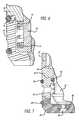
- FIG. 1is a first side view of one embodiment of miniature poppet valve in accordance with the present invention.
- FIG. 2is an exploded perspective view of the miniature poppet valve of FIG. 1 .
- FIG. 3is a cross sectional view of the miniature poppet valve taken along line 3 — 3 of FIG. 1 .
- FIG. 4is an enlarged partial view of region 4 of FIG. 3 .
- FIG. 5is an end view of the miniature poppet valve taken along line 5 — 5 of FIG. 1 .
- FIG. 6is a local cross sectional view of an alternate embodiment of the present invention.
- FIG. 7is a local cross-sectional view of another alternate embodiment of the present invention.
- FIG. 8is a copy of an actual trace of current versus time during the actuation of a valve in accordance with the present invention.
- FIG. 9is a block diagram of an exemplary coil drive system incorporating arrival sensing circuitry.
- the present inventionis a miniature electromagnetically operated pneumatic poppet valve assembly 10 having a unique construction facilitating its small size and low mass.
- the poppet valve assembly 10is of the two-way, two position type of fluid valve.
- the valve bodyis approximately 0.35 inches (10 millimeters) in diameter and approximately 0.75 inches (19 millimeters) long.
- the major parts of the poppet valve assembly 10including an armature assembly, a return spring, two stationary parts of the magnetic circuit, a valve seat member and an electromagnetic actuator coil, are assembled using one press fit for the two major components of the magnetic circuit, and a single “snap” or press or barb fit, or a combination of the foregoing, of the valve seat to the foregoing assembly.
- a potting operationthen secures the actuator coil and a printed circuit board connector in position, completing the assembly.
- the sealing tipis directly molded to the armature in the embodiment shown in FIGS. 3 and 6, allowing for low mass and space conservation in the valve interior.
- the resultis a press-fit assembly directly connected to a printed circuit board without wires, and with the poles themselves forming the upper portion of the enclosure, and in the preferred embodiment, being generally intended to be tamper-proof even at the time of manufacture.
- the miniature poppet valve assembly 10 of the embodiment shown thereinhas a cylindrical body 20 , an end cap assembly 22 and a valve seat member 24 .
- the valve seat member 24has an O-ring or other sealing member 26 positioned in an O-ring groove therein and a second O-ring or still other sealing member 28 , also positioned in an O-ring groove therein, with one or more (e.g., four) ports 30 defined through a recessed section 32 of the valve seat member 24 between O-rings 26 and 28 providing fluid communication with the inside of the valve seat member 24 .
- a second portgenerally indicated by the numeral 34 , details of which are better described with respect to subsequent Figures. Assembly of the valve, in itself, preloads the tip to port to form the sealed enclosure.
- FIG. 3a cross-sectional view of the miniature poppet valve assembly 10 of FIGS. 1 and 2 may be seen.
- the cylindrical body 20 shown in FIG. 1is actually the lower pole piece 36 of FIGS. 2 and 3, which together with upper pole piece 38 forms most or a substantial portion of the outer enclosure of the poppet valve assembly 10 as well the stationary part of the magnetic circuit, entrapping the electromagnetic actuator coil 40 therein.
- a movable armature 42Positioned within the lower pole piece 36 is a movable armature 42 having a valve closure member 44 integrated at the lower end thereof.
- the valve closure memberpreferably formed of a compliant and/or lighter weight rubber or plastic material, such as Nitrile or Viton, may be molded into, or pressed, cemented or otherwise connected to the armature 42 .
- a return spring 46acting between the lower pole piece 36 and an annular shoulder 47 formed on the lower end of the armature, biases the armature to the valve closed position shown in FIG. 3, cutting off fluid communication between port 34 and ports 30 .
- Electrical excitation of the actuator coil 40will provide a magnetic attractive force on the upper end of the armature to pull the armature flat against the adjacent surface of the upper pole piece 38 , pulling the valve closure member 44 away from the adjacent valve seat 49 in the valve seat member 24 to establish fluid communication between port 34 and port(s) 30 .
- the “pressing” and/or welding of members 38 , 36 and 24create a “leak free” valve so that all fluid that passes through 34 exits through 30 .
- the end cap assembly 22(FIG. 1 ), which includes the upper pole piece 38 , may be seen in the exploded view of FIG. 2 .
- the upper pole piece 38 in this embodimenthas a relatively large slot 48 formed across the top thereof, with two holes 50 there through (only one being visible in FIG. 2) for the two electrical lead wires (not shown) of the actuator coil 40 .
- These leadsare connected to terminals 52 , forming a miniature connector 54 fitting within slot 48 in the upper pole piece 38 .
- the coil 40may be wound on a fixture without a bobbin or, as in a preferred embodiment, a bobbin such as bobbin 56 (FIG. 2) may be used.
- the connector 54fits within slot 48 in the upper pole piece 38 , with the rest of the slot being potted, typically with a suitable thermosetting resin to retain the connector, encapsulate the lead wires for coil 40 and to bond the bobbin 56 in place through holes 50 in the upper pole piece 38 so as to prevent any movement of the actuator coil 40 in the final assembly.
- the pottinggenerally illustrated by the numeral 58 in FIG. 2, may be done in a fixture, or alternatively, in a preformed cap, such as an injection molded cap generally in the shape shown, may be used, both as the potting fixture for each respective poppet valve and as a permanent part of the valve.
- the cap and/or the pottingis confined to the slot 48 (FIG. 2 ).
- the valvecan be directly (with pins) connected to a printed circuit board. No wires or intermediate connectors are needed.
- FIG. 5a bottom view of the valve seat member 24 may be seen.
- the valve seat memberhas an opening or port 34 (see also FIGS. 1 and 3 ), terminating at the inner end thereof to form a valve seat cooperatively disposed with respect to the valve closure member 44 .
- Extending in multiple (e.g., four) radial directions from the port 34are slots 60 (see FIGS. 1, 3 and 5 ), formed in the valve seat member 24 to provide fluid flow passages communicating with the port 34 , even if the poppet valve assembly 10 is used in an application having the end 62 thereof flat against a mounting surface for the valve.
- These slotsfurther serve to reduce the length of the valve by making the fluid passage an integral part of the seat.
- valve seat member 24has a cooperatively disposed annular recess 64 for receiving and retaining the annular protrusion 62 on the lower pole piece 36 .
- valve seat member 24is a molded non-metallic member having sufficient compliance to allow pressing of the lower end of the lower pole piece 36 into the top of the valve seat member to provide a tight snap fit of these two pieces. Delrin material is used in one embodiment.
- the lower pole piece 36 , the upper pole piece 38 and the armature 42are formed of magnetic materials, typically but not necessarily, all the same material, and preferably a ferromagnetic material preferably selected in part to provide minimum wear characteristics and high magnetic hysteresis. While any of a number of materials may be used, one useful material is 4140 steel.
- the upper pole piece 38 and the lower pole piece 36are dimensioned to provide a press fit there between.
- the actuator coil 40in position (in the embodiment shown, already assembled as part of the end cap assembly 22 )
- the upper pole piece 38 and the lower pole piece 36may be permanently pressed together.
- a suitable bonding techniquesuch as laser welding or an adhesive cement may used to enhance the joining of these two parts, or used as an alternative to a press fit.
- the top of the lower pole piece 36 or the bottom of the upper pole piece 38may be rolled into a slight groove provided for that purpose, though at least in some applications for reduced wear, the magnetic materials may be mechanically too hard for normal rolling operations.
- this jointpreferably be treated as a permanent joint, as the parts are too small and/or of relatively low cost to incorporate fasteners or fastening techniques allowing disassembly and reassembly as desired.
- the armature assembly(armature 42 with valve closure member 44 thereon) and mechanical return spring 46 are put in position.
- the valve seat member 24is pressed onto the lower end of the lower pole piece 36 to “snap” into its final assembly position.
- the O-rings 26 and 28are then typically added thereto.
- the O-ringsfacilitate a particular type of mounting, though other types of mounting and sealing of the valve may be incorporated as desired.
- flange mounting with tube connectionsmay be used, preferably by providing a flange on typically the lower pole piece 36 or the valve seat member 24 .
- rubbercould be molded to 34 in place of O-rings to form one piece.
- the net resultis a miniature solenoid-operated pneumatic valve assembly 10 having a minimum number of parts and permanently assembled, suitable for use in controlling the flow of gasses or liquids, depending on the application of the valve.
- the armature 42While the lower end of the armature 42 is shown are having an annular flange-like protrusion for capturing the return spring 46 , the flange-like protrusion may be scalloped or otherwise discontinuous in regions to increase the internal fluid flow area within the valve seat member 24 and reduce viscous effects restraining flow and/or operation of the valve.
- valve assemblies 10 of the present inventionmay be used for high speed control of fluid flow in either direction. If with the valve closed, the relatively higher fluid pressure is on port 34 , then the return spring 46 must have an adequate force to hold the valve closure member 44 closed against its seat despite the differential pressure encouraging the valve closure member 44 towards the open position, yet not so high a force as to prevent overpowering the return spring 46 by the magnetic forces generated by the actuator coil 40 to open the valve. If with the valve closure member 44 closed, the relatively lower fluid pressure is on port 34 , then the magnetic forces generated by the actuator coil 40 to open the valve closure member 44 must exceed the force holding the valve closure member 44 closed against the differential pressure across the valve closure member plus the force of the return spring.
- the return springis selected so that the actuator coil 40 may be pulsed with an electrical current pulse to open the valve closure member 44 against a differential fluid pressure helping to hold the valve closure member 44 closed.
- the armature 42 and valve closure member 44are capable of very high speeds and frequencies of operation between their open and closed positions. After termination of the electrical current pulse, the residual magnetism of the components of the magnetic circuit provides an attractive magnetic force exceeding the return spring force in order to hold (i.e., magnetically latch) the armature 42 (and consequently, the valve closure member 44 ) open. This allows opening the valve for a substantial period of time using only a short electrical current pulse for maximum opening force.
- Electrical current pulsescan therefore be used that would otherwise overheat and damage the actuator coil 40 if such an electrical current level was maintained throughout a substantial valve open period. This also reduces the size of the actuator coil drive circuitry needed.
- a short, lower amplitude electrical current pulse in the opposite directionmay be used to substantially demagnetize the components of the magnetic circuit, thereby allowing the return spring to close the valve.
- Alternative embodimentsmay utilize a fast decaying sinusoid of current to cancel the latching force and allow the valve to close.
- valves of other sizessuch as by way of example, valves of approximately 0.5 inch (13 millimeters) in diameter and approximately 1.0 inches (25 millimeters) long. Even larger valves may be made in accordance with the present invention, though particularly large valves are more amenable, physically and economically, to inclusion of reversible assembly techniques.
- FIG. 6a cross-section similar to the cross-section of FIG. 4, but of an alternate embodiment, may be seen.
- This embodimentotherwise may be identical to the embodiment of FIGS. 1 through 5 and FIG. 7 .
- plastic members 70 and 72are interposed between spring 46 and lower pole piece 36 , and spring 46 and moveable armature 42 ′, respectively. These plastic members prevent metal-to-metal contact between the spring and the respective adjacent members and thereby avoid possible wear and formation of debris by any motion between the respective metal members.
- the lower pole piece 36 ′has an integral barb 74 formed on the annular protrusion 76 , which barb 74 has an interference fit with the inner diameter of the valve seat member 24 ′.
- the cross-section of FIG. 6is a cross-section similar to that of FIG. 4 for the prior embodiment, though taken at a 45° angle between ports 30 , that is, halfway between ports 30 (see FIGS. 1, 3 and 4 ) in the valve seat member 24 ′.
- valve seat member 24 ′itself initially may or may not have a corresponding indentation, and accordingly, the barb will automatically seat with the parts at the fully assembled position. If desired, the setting of the barb may be aided by pressing or rolling, or by application of ultrasonic energy around the periphery of the valve seat member 24 ′.
- the inner diameter of the valve seat member 24 ′has molded-in vertical grooves in the regions of the ports 30 (FIG. 1) to provide a greater flow area through the valve, and accordingly, the barbs interact with the inner diameter of the valve seat member 24 ′ only in the regions between the ports.
- the upper pole piece 78 and lower pole piece 80may be welded together using an appropriate fixture to maintain alignment of the two parts during welding.
- the valve seat member in the previous embodimentsis comprised of two members 82 and 84 , with member 80 having an O-ring 86 limiting or preventing airflow past the O-ring.
- the moveable armature 42 ′′includes an integral lower umbrella-like protrusion 88 retaining elastomeric O-ring 90 providing the seal on valve closure.
- members 82 and 84 and lower pole piece 80may be fastened together using a press fit, though other forms of assembly of these parts, and/or of the upper and lower pole pieces may be used as desired.
- Another aspect of the present inventionis the ability to sense the arrival of the moveable armature 42 (or 42 ′ or 42 ′′) at its actuated position.
- the principle allowing the sensingcan be shown as follows. Assume for the moment that the resistance of the actuator coil 40 (see FIGS. 2 and 3) is a particular value, the permeability of the magnetic circuit is very high, and saturation and leakage effects are neglected.
- the inductance of the coilwill be:
- FIG. 8a copy of an actual trace showing current waveform versus time during the actuation of a valve in accordance with the present invention may be seen.
- the rate of change of current in the actuatorcan easily be sensed by various means.
- onemay sense the current in the coil, such as by a series resistor, and with analog circuitry, sense the sudden change in di/dt by sensing d 2 i/dt 2 using a pair of series connected differentiating circuits.
- the sudden change in di/dt from a substantial negative value to a very substantial positive valuewill exhibit itself as a large spike in d 2 i/dt 2 .
- Itmay also be sensed by peak detectors by sensing the first peak in the current to enable a second detector to detect the following minimum current.
- the dL/dt termmay not become larger than the applied voltage before the actuator reaches the actuated position. However, even then, the di/dt term will decrease (but not go negative) until the actuator reaches the actuated position, after which the di/dt term will take a step jump to a more positive value. Consequently, the arrival of the actuator at the actuated position is indicated by a sudden increase in the di/dt term after actuation has begun, again indicated by a spike in d 2 i/dt 2 . In either case, the indication of arrival may be used to terminate the power to the valve if magnetic latching is used, typically after allowing for a possible debounce time.
- the actuation currentmay be reduced to a much lower holding current. This reduces power consumption and allows an overdrive of the coil, if desired or needed for speed purposes, without overheating the coil. Sensing full actuation in this manner can also be used for diagnostic purposes by noting an increase or irregularity in the actuation times of each valve.
- FIG. 9A block diagram for an exemplary coil excitation control circuit incorporating this feature may be seen in FIG. 9 .
- the actuation commandis provided to the coil drive circuit, which provides electrical power to a series combination of the coil and a sense resistor, the sense resistor being between the coil and ground for convenience.
- the arrival sense circuitsenses the voltage across the sense resistor to determine the arrival of the moveable armature 42 ( 42 ′, 42 ′′) at the actuated position, and provides a feedback signal, preferably after an adequate debounce time, to turn off the coil drive if magnetic latching is used, or to reduce the output of the coil drive circuit if magnetic latching is not used, in which case termination of the holding current releases the moveable armature 42 ( 42 ′, 42 ′′).
Landscapes
- Engineering & Computer Science (AREA)
- General Engineering & Computer Science (AREA)
- Mechanical Engineering (AREA)
- Magnetically Actuated Valves (AREA)
- Valve Housings (AREA)
Abstract
Description


Claims (25)
Priority Applications (7)
| Application Number | Priority Date | Filing Date | Title |
|---|---|---|---|
| US10/361,135US6722628B1 (en) | 2003-02-06 | 2003-02-06 | Miniature poppet valve assembly |
| KR1020057014539AKR101045991B1 (en) | 2003-02-06 | 2004-01-30 | Electromagnetic valve assembly |
| DE112004000264.8TDE112004000264B4 (en) | 2003-02-06 | 2004-01-30 | Electromagnetic valve arrangement |
| JP2006503196AJP2006517280A (en) | 2003-02-06 | 2004-01-30 | Electromagnetic valve assembly |
| PCT/US2004/002697WO2004072522A1 (en) | 2003-02-06 | 2004-01-30 | Electromagnetic valve assembly |
| CNB2004800094592ACN100396981C (en) | 2003-02-06 | 2004-01-30 | Electromagnetic valve assembly |
| SE0501771ASE528932C2 (en) | 2003-02-06 | 2005-08-03 | Electromagnetic valve assembly |
Applications Claiming Priority (1)
| Application Number | Priority Date | Filing Date | Title |
|---|---|---|---|
| US10/361,135US6722628B1 (en) | 2003-02-06 | 2003-02-06 | Miniature poppet valve assembly |
Publications (1)
| Publication Number | Publication Date |
|---|---|
| US6722628B1true US6722628B1 (en) | 2004-04-20 |
Family
ID=32069554
Family Applications (1)
| Application Number | Title | Priority Date | Filing Date |
|---|---|---|---|
| US10/361,135Expired - LifetimeUS6722628B1 (en) | 2003-02-06 | 2003-02-06 | Miniature poppet valve assembly |
Country Status (7)
| Country | Link |
|---|---|
| US (1) | US6722628B1 (en) |
| JP (1) | JP2006517280A (en) |
| KR (1) | KR101045991B1 (en) |
| CN (1) | CN100396981C (en) |
| DE (1) | DE112004000264B4 (en) |
| SE (1) | SE528932C2 (en) |
| WO (1) | WO2004072522A1 (en) |
Cited By (33)
| Publication number | Priority date | Publication date | Assignee | Title |
|---|---|---|---|---|
| US20020118057A1 (en)* | 1999-08-31 | 2002-08-29 | Leonard Forbes | Integrated circuit and method for minimizing clock skews |
| US20060076530A1 (en)* | 2004-08-20 | 2006-04-13 | Ieda Joao J C | Linear solenoid for EGR valve |
| US20060219496A1 (en)* | 2005-03-30 | 2006-10-05 | Dimig Steven J | Residual magnetic devices and methods |
| US20060219513A1 (en)* | 2005-03-30 | 2006-10-05 | Organek Gregory J | Residual magnetic devices and methods |
| US20060219499A1 (en)* | 2005-03-30 | 2006-10-05 | Organek Gregory J | Residual magnetic devices and methods |
| US20060219498A1 (en)* | 2005-03-30 | 2006-10-05 | Organek Gregory J | Residual magnetic devices and methods |
| US20060219497A1 (en)* | 2005-03-30 | 2006-10-05 | Organek Gregory J | Residual magnetic devices and methods |
| US20060226942A1 (en)* | 2005-03-30 | 2006-10-12 | Dimig Steven J | Residual magnetic devices and methods |
| US20060227488A1 (en)* | 2005-03-30 | 2006-10-12 | Dimig Steven J | Residual magnetic devices and methods |
| US20060226941A1 (en)* | 2005-03-30 | 2006-10-12 | Dimig Steven J | Residual magnetic devices and methods |
| US20060225985A1 (en)* | 2005-03-30 | 2006-10-12 | Dimig Steven J | Residual magnetic devices and methods |
| US20060226939A1 (en)* | 2005-03-30 | 2006-10-12 | Dimig Steven J | Residual magnetic devices and methods |
| US20060238285A1 (en)* | 2005-03-30 | 2006-10-26 | Dimig Steven J | Residual magnetic devices and methods |
| US20060237959A1 (en)* | 2005-03-30 | 2006-10-26 | Dimig Steven J | Residual magnetic devices and methods |
| US20060238284A1 (en)* | 2005-03-30 | 2006-10-26 | Dimig Steven J | Residual magnetic devices and methods |
| US20070235092A1 (en)* | 2006-04-06 | 2007-10-11 | Fastest, Inc. | Latching connectors |
| US20080210898A1 (en)* | 2007-03-02 | 2008-09-04 | Paul Hedding | One-piece spring and poppet incorporated into a valve seat assembly and associated method for manufacturing a one-piece spring and poppet |
| US20090026985A1 (en)* | 2006-01-26 | 2009-01-29 | Knorr-Bremse Systeme Fuer Nutzfahrzeuge Gmbh | Method for Actuating an Electromagnetic Valve |
| US20090183698A1 (en)* | 2008-01-17 | 2009-07-23 | Eto Magnetic Gmbh | Electromagnetically actuated valve device |
| US20090278067A1 (en)* | 2006-03-21 | 2009-11-12 | Christoph Voss | Solenoid Valve |
| US20100028748A1 (en)* | 2006-09-14 | 2010-02-04 | Societe Bic | Device for Refilling a Fuel Cartridge for a Fuel Cell |
| EP1962299A3 (en)* | 2007-02-23 | 2010-04-28 | Robert Bosch GmbH | Electro-pneumatic cartridge valve and method for simplified manufacture of the same |
| US20100155629A1 (en)* | 2008-12-18 | 2010-06-24 | Hunnicutt Harry A | Pilot valve for control valve |
| US7891637B2 (en) | 2006-11-07 | 2011-02-22 | Angstrom Power Incorporated | Magnetic fluid coupling assemblies and methods |
| US20130112904A1 (en)* | 2010-08-05 | 2013-05-09 | Fluid Automation Systems S.A. | Solenoid valve with a two-part core |
| WO2013130428A1 (en)* | 2012-02-29 | 2013-09-06 | Vernay Laboratories, Inc. | Magneto-rheological elastomeric fluid control armature assembly |
| US20140246615A1 (en)* | 2013-03-04 | 2014-09-04 | Emerson Electric Co. | Systems and Apparatuses for a Simplified Solenoid Valve Assembly |
| US10520334B2 (en) | 2015-03-20 | 2019-12-31 | Dana Automotive Systems Group, Llc | Induction based position sensing in an electromagnetic actuator |
| US10871242B2 (en) | 2016-06-23 | 2020-12-22 | Rain Bird Corporation | Solenoid and method of manufacture |
| US10980120B2 (en) | 2017-06-15 | 2021-04-13 | Rain Bird Corporation | Compact printed circuit board |
| US11503782B2 (en) | 2018-04-11 | 2022-11-22 | Rain Bird Corporation | Smart drip irrigation emitter |
| US11721465B2 (en) | 2020-04-24 | 2023-08-08 | Rain Bird Corporation | Solenoid apparatus and methods of assembly |
| WO2025174720A1 (en)* | 2024-02-13 | 2025-08-21 | Mac Valves, Inc. | Valve having a quad ring seal |
Families Citing this family (8)
| Publication number | Priority date | Publication date | Assignee | Title |
|---|---|---|---|---|
| KR100738127B1 (en)* | 2005-09-02 | 2007-07-10 | 현대자동차주식회사 | Belt tension control system and control method of intermittent driving vehicle equipped with belt driven type IS |
| CN102493785A (en)* | 2011-12-02 | 2012-06-13 | 中国石油集团长城钻探工程有限公司 | Automatic control sleeve valve |
| KR101650861B1 (en)* | 2014-07-16 | 2016-08-24 | 임태호 | a flow regulating valve-STRUCTURE for gas range |
| US10578226B2 (en)* | 2016-12-22 | 2020-03-03 | Mac Valves, Inc. | Valve with two-piece adjustable can with integral pole piece |
| CN108194684B (en)* | 2018-01-10 | 2019-05-24 | 厦门佳普乐电子科技有限公司 | A kind of intellectual water closet electromagnetism valve seal control method and control circuit |
| AT16152U1 (en)* | 2018-03-01 | 2019-02-15 | Ing Andreas Zieger Dipl | Sealing system for valve |
| US20200360875A1 (en) | 2019-05-14 | 2020-11-19 | Sodastream Industries Ltd. | Carbonation machine and a gas canister for a carbonation machine |
| CN111810697B (en)* | 2020-01-07 | 2022-02-08 | 浙江工业大学 | High-dynamic control system and method for electromagnetic valve based on voltage pulse width modulation technology |
Citations (29)
| Publication number | Priority date | Publication date | Assignee | Title |
|---|---|---|---|---|
| US3570806A (en) | 1969-01-14 | 1971-03-16 | Bell Aerospace Corp | Balanced electromechanical control valve |
| US3683239A (en) | 1971-06-17 | 1972-08-08 | Oded E Sturman | Self-latching solenoid actuator |
| US3743898A (en) | 1970-03-31 | 1973-07-03 | Oded Eddie Sturman | Latching actuators |
| US4018419A (en) | 1975-01-06 | 1977-04-19 | Societe Anonyme D.B.A. | Miniature solenoid valve |
| US4323003A (en) | 1980-03-24 | 1982-04-06 | Clippard Instrument Laboratory, Inc. | Fluid cylinder with replaceable rod seal and guide |
| US4409638A (en) | 1981-10-14 | 1983-10-11 | Sturman Oded E | Integrated latching actuators |
| US5127625A (en) | 1990-02-19 | 1992-07-07 | Avl Medical Instruments Ag | Electromagnetically actuated valve |
| US5251659A (en) | 1991-07-22 | 1993-10-12 | Sturman Oded E | High speed miniature solenoid |
| US5301875A (en) | 1990-06-19 | 1994-04-12 | Cummins Engine Company, Inc. | Force balanced electronically controlled fuel injector |
| US5407131A (en) | 1994-01-25 | 1995-04-18 | Caterpillar Inc. | Fuel injection control valve |
| US5483411A (en) | 1993-04-22 | 1996-01-09 | Sturman; Oded E. | Chatterless low power AC solenoid without pole shading |
| US5494219A (en) | 1994-06-02 | 1996-02-27 | Caterpillar Inc. | Fuel injection control valve with dual solenoids |
| US5584465A (en) | 1993-12-07 | 1996-12-17 | Snap-Tite, Inc. | Solenoid latching valve |
| US5584466A (en) | 1993-10-21 | 1996-12-17 | Smc Corporation | Self-holding type solenoid valves |
| US5640987A (en) | 1994-04-05 | 1997-06-24 | Sturman; Oded E. | Digital two, three, and four way solenoid control valves |
| US5641148A (en) | 1996-01-11 | 1997-06-24 | Sturman Industries | Solenoid operated pressure balanced valve |
| US5711347A (en) | 1996-08-27 | 1998-01-27 | Sturman; Oded E. | Double solenoid latching ball valve with a hollow ball |
| US5718264A (en) | 1996-06-10 | 1998-02-17 | Sturman Industries | High speed 3-way control valve |
| US5836230A (en) | 1996-08-27 | 1998-11-17 | Oded E. Sturman | High speed 2-way control valve |
| US5954030A (en) | 1994-12-01 | 1999-09-21 | Oded E. Sturman | Valve controller systems and methods and fuel injection systems utilizing the same |
| US5961052A (en)* | 1997-09-25 | 1999-10-05 | Caterpillar Inc. | Control valve having a top mounted single pole solenoid for a fuel injector |
| US6036120A (en)* | 1998-03-27 | 2000-03-14 | General Motors Corporation | Fuel injector and method |
| US6035895A (en) | 1998-01-26 | 2000-03-14 | Sturman Bg, Llc | Three-way latching fluid valve |
| US6079435A (en)* | 1996-11-14 | 2000-06-27 | Foxboro Eckardt Gmbh | Current to pressure converter |
| US6116276A (en) | 1998-02-09 | 2000-09-12 | Sturman Bg, Llc | Balance latching fluid valve |
| US6129115A (en) | 1999-07-02 | 2000-10-10 | Mac Valves, Inc. | Self-latching solenoid valve assembly |
| US6220569B1 (en) | 2000-01-07 | 2001-04-24 | Clippard Instrument Laboratory, Inc. | Electrically controlled proportional valve |
| US6386218B1 (en)* | 2000-08-17 | 2002-05-14 | Eaton Corporation | Solenoid operated valve assembly for variable bleed pressure proportional control |
| US6644622B2 (en)* | 2001-11-14 | 2003-11-11 | Siemens Vdo Automotive Inc. | Emission control valve having a robust solenoid actuator |
Family Cites Families (34)
| Publication number | Priority date | Publication date | Assignee | Title |
|---|---|---|---|---|
| JPS5175222A (en)* | 1974-12-25 | 1976-06-29 | Konan Electric Co | |
| JPS52105326A (en)* | 1976-02-28 | 1977-09-03 | Konan Electric Co | Two stable formed electromagnetic valve |
| JPS6138166Y2 (en)* | 1978-11-30 | 1986-11-05 | ||
| FR2530771A1 (en)* | 1982-07-21 | 1984-01-27 | Sibe | SOLENOID VALVE WITH PLASTIC SHUTTER |
| DE3229835A1 (en)* | 1982-08-11 | 1984-02-16 | Hermann Hemscheidt Maschinenfabrik Gmbh & Co, 5600 Wuppertal | ARRANGEMENT FOR CONTROLLING AN ELECTRO-HYDRAULIC VALVE |
| JPS60184471U (en)* | 1984-05-17 | 1985-12-06 | エヌ・オー・ケー・エフテック株式会社 | gas shutoff valve |
| US4643393A (en)* | 1985-03-13 | 1987-02-17 | Shoketsu Kinzoku Kogyo Kabushiki Kaisha | Electromagnetic valve |
| JPS62167985A (en)* | 1986-01-17 | 1987-07-24 | Taimu Giken Kk | Electromagnetic valve and detecting method for its operating condition |
| JPS63297883A (en)* | 1987-05-28 | 1988-12-05 | Matsushita Refrig Co | Selector valve |
| JPH0198981U (en)* | 1987-12-24 | 1989-07-03 | ||
| JPH01224581A (en)* | 1988-03-03 | 1989-09-07 | Toyota Autom Loom Works Ltd | Solenoid valve for capacity control in compressor and drive control thereof |
| JPH0224177U (en)* | 1988-08-02 | 1990-02-16 | ||
| JPH032982U (en)* | 1989-05-31 | 1991-01-11 | ||
| JPH0744870Y2 (en)* | 1989-09-30 | 1995-10-11 | 矢崎総業株式会社 | Gas shutoff valve |
| JPH03234985A (en)* | 1990-02-13 | 1991-10-18 | Koganei Ltd | Electromagnetic valve |
| US5085402A (en)* | 1990-08-10 | 1992-02-04 | The Lee Company | High speed solenoid valve actuator |
| JP3119274B2 (en)* | 1991-09-09 | 2000-12-18 | 株式会社日立製作所 | Solenoid valve and manufacturing method thereof |
| JPH0617959A (en)* | 1991-12-09 | 1994-01-25 | Ouken Seiko Kk | Solenoid valve |
| JP3099207B2 (en)* | 1992-03-03 | 2000-10-16 | 応研精工株式会社 | solenoid valve |
| US5598871A (en)* | 1994-04-05 | 1997-02-04 | Sturman Industries | Static and dynamic pressure balance double flow three-way control valve |
| US6308690B1 (en)* | 1994-04-05 | 2001-10-30 | Sturman Industries, Inc. | Hydraulically controllable camless valve system adapted for an internal combustion engine |
| US5488340A (en)* | 1994-05-20 | 1996-01-30 | Caterpillar Inc. | Hard magnetic valve actuator adapted for a fuel injector |
| JPH09303602A (en)* | 1996-05-07 | 1997-11-28 | Tokyo Danreiki Seisakusho:Kk | Self-holding solenoid valve |
| US5813841A (en)* | 1996-05-16 | 1998-09-29 | Sturman Industries | Hydraulic pressure control system for a pump |
| GB9613730D0 (en)* | 1996-07-01 | 1996-09-04 | Perkins Ltd | An electro-magnetically operated valve |
| DE19650865A1 (en)* | 1996-12-07 | 1998-06-10 | Bosch Gmbh Robert | magnetic valve |
| EP0870958A1 (en)* | 1997-04-08 | 1998-10-14 | Wärtsilä NSD Schweiz AG | Solenoid valve for hydraulic fluids |
| JPH1163278A (en)* | 1997-08-28 | 1999-03-05 | Hosiden Corp | Solenoid valve |
| US6086042A (en)* | 1998-04-08 | 2000-07-11 | Wabash Magnetics, Inc. | Fluid resistant solenoid actuated valve |
| EP1006302A1 (en)* | 1998-11-30 | 2000-06-07 | Wärtsilä NSD Schweiz AG | Solenoid valve for hydraulic fluids |
| ATE287057T1 (en)* | 2000-12-19 | 2005-01-15 | Fluid Automation Syst | ELECTRIC SOLENOID VALVE |
| JP3494221B2 (en)* | 2000-12-25 | 2004-02-09 | Smc株式会社 | Self-holding solenoid valve |
| US20030042451A1 (en)* | 2001-08-29 | 2003-03-06 | Eaton Corporation. | Solenoid operated valve with integral magnetic separator |
| CN2517939Y (en)* | 2001-12-10 | 2002-10-23 | 李岱峰 | Electromagnetic valve |
- 2003
- 2003-02-06USUS10/361,135patent/US6722628B1/ennot_activeExpired - Lifetime
- 2004
- 2004-01-30DEDE112004000264.8Tpatent/DE112004000264B4/ennot_activeExpired - Lifetime
- 2004-01-30KRKR1020057014539Apatent/KR101045991B1/ennot_activeExpired - Lifetime
- 2004-01-30JPJP2006503196Apatent/JP2006517280A/enactivePending
- 2004-01-30CNCNB2004800094592Apatent/CN100396981C/ennot_activeExpired - Lifetime
- 2004-01-30WOPCT/US2004/002697patent/WO2004072522A1/enactiveApplication Filing
- 2005
- 2005-08-03SESE0501771Apatent/SE528932C2/enunknown
Patent Citations (31)
| Publication number | Priority date | Publication date | Assignee | Title |
|---|---|---|---|---|
| US3570806A (en) | 1969-01-14 | 1971-03-16 | Bell Aerospace Corp | Balanced electromechanical control valve |
| US3743898A (en) | 1970-03-31 | 1973-07-03 | Oded Eddie Sturman | Latching actuators |
| US3683239A (en) | 1971-06-17 | 1972-08-08 | Oded E Sturman | Self-latching solenoid actuator |
| US4018419A (en) | 1975-01-06 | 1977-04-19 | Societe Anonyme D.B.A. | Miniature solenoid valve |
| US4323003A (en) | 1980-03-24 | 1982-04-06 | Clippard Instrument Laboratory, Inc. | Fluid cylinder with replaceable rod seal and guide |
| US4409638A (en) | 1981-10-14 | 1983-10-11 | Sturman Oded E | Integrated latching actuators |
| US5127625A (en) | 1990-02-19 | 1992-07-07 | Avl Medical Instruments Ag | Electromagnetically actuated valve |
| US5301875A (en) | 1990-06-19 | 1994-04-12 | Cummins Engine Company, Inc. | Force balanced electronically controlled fuel injector |
| US5251659A (en) | 1991-07-22 | 1993-10-12 | Sturman Oded E | High speed miniature solenoid |
| US5304971A (en) | 1991-07-22 | 1994-04-19 | Sturman Oded E | High speed miniature solenoid |
| US5483411A (en) | 1993-04-22 | 1996-01-09 | Sturman; Oded E. | Chatterless low power AC solenoid without pole shading |
| US5584466A (en) | 1993-10-21 | 1996-12-17 | Smc Corporation | Self-holding type solenoid valves |
| US5584465A (en) | 1993-12-07 | 1996-12-17 | Snap-Tite, Inc. | Solenoid latching valve |
| US5407131A (en) | 1994-01-25 | 1995-04-18 | Caterpillar Inc. | Fuel injection control valve |
| US5640987A (en) | 1994-04-05 | 1997-06-24 | Sturman; Oded E. | Digital two, three, and four way solenoid control valves |
| US5494219A (en) | 1994-06-02 | 1996-02-27 | Caterpillar Inc. | Fuel injection control valve with dual solenoids |
| US5954030A (en) | 1994-12-01 | 1999-09-21 | Oded E. Sturman | Valve controller systems and methods and fuel injection systems utilizing the same |
| US5641148A (en) | 1996-01-11 | 1997-06-24 | Sturman Industries | Solenoid operated pressure balanced valve |
| US5718264A (en) | 1996-06-10 | 1998-02-17 | Sturman Industries | High speed 3-way control valve |
| US5836230A (en) | 1996-08-27 | 1998-11-17 | Oded E. Sturman | High speed 2-way control valve |
| US5711347A (en) | 1996-08-27 | 1998-01-27 | Sturman; Oded E. | Double solenoid latching ball valve with a hollow ball |
| US6079435A (en)* | 1996-11-14 | 2000-06-27 | Foxboro Eckardt Gmbh | Current to pressure converter |
| US5961052A (en)* | 1997-09-25 | 1999-10-05 | Caterpillar Inc. | Control valve having a top mounted single pole solenoid for a fuel injector |
| US6035895A (en) | 1998-01-26 | 2000-03-14 | Sturman Bg, Llc | Three-way latching fluid valve |
| US6116276A (en) | 1998-02-09 | 2000-09-12 | Sturman Bg, Llc | Balance latching fluid valve |
| US6234202B1 (en) | 1998-02-09 | 2001-05-22 | Sturman Bg, Llc | Balanced fluid control valve |
| US6036120A (en)* | 1998-03-27 | 2000-03-14 | General Motors Corporation | Fuel injector and method |
| US6129115A (en) | 1999-07-02 | 2000-10-10 | Mac Valves, Inc. | Self-latching solenoid valve assembly |
| US6220569B1 (en) | 2000-01-07 | 2001-04-24 | Clippard Instrument Laboratory, Inc. | Electrically controlled proportional valve |
| US6386218B1 (en)* | 2000-08-17 | 2002-05-14 | Eaton Corporation | Solenoid operated valve assembly for variable bleed pressure proportional control |
| US6644622B2 (en)* | 2001-11-14 | 2003-11-11 | Siemens Vdo Automotive Inc. | Emission control valve having a robust solenoid actuator |
Non-Patent Citations (1)
| Title |
|---|
| Clippard Instrument Laboratory, Inc., "Parting Thoughts", Fluid Power Journal, Nov./Dec. 2002, p. 40, Palmer, PA. |
Cited By (48)
| Publication number | Priority date | Publication date | Assignee | Title |
|---|---|---|---|---|
| US20020118057A1 (en)* | 1999-08-31 | 2002-08-29 | Leonard Forbes | Integrated circuit and method for minimizing clock skews |
| US7575219B2 (en)* | 2004-08-20 | 2009-08-18 | Wahler Metalurgica, Ltda. | Linear solenoid for EGR valve |
| US20060076530A1 (en)* | 2004-08-20 | 2006-04-13 | Ieda Joao J C | Linear solenoid for EGR valve |
| US20060227488A1 (en)* | 2005-03-30 | 2006-10-12 | Dimig Steven J | Residual magnetic devices and methods |
| US8403124B2 (en) | 2005-03-30 | 2013-03-26 | Strattec Security Corporation | Residual magnetic devices and methods |
| US20060219498A1 (en)* | 2005-03-30 | 2006-10-05 | Organek Gregory J | Residual magnetic devices and methods |
| US20060219497A1 (en)* | 2005-03-30 | 2006-10-05 | Organek Gregory J | Residual magnetic devices and methods |
| US20060226942A1 (en)* | 2005-03-30 | 2006-10-12 | Dimig Steven J | Residual magnetic devices and methods |
| US8149557B2 (en) | 2005-03-30 | 2012-04-03 | Strattec Security Corporation | Residual magnetic devices and methods |
| US20060226941A1 (en)* | 2005-03-30 | 2006-10-12 | Dimig Steven J | Residual magnetic devices and methods |
| US20060225985A1 (en)* | 2005-03-30 | 2006-10-12 | Dimig Steven J | Residual magnetic devices and methods |
| US20060226939A1 (en)* | 2005-03-30 | 2006-10-12 | Dimig Steven J | Residual magnetic devices and methods |
| US20060238285A1 (en)* | 2005-03-30 | 2006-10-26 | Dimig Steven J | Residual magnetic devices and methods |
| US20060237959A1 (en)* | 2005-03-30 | 2006-10-26 | Dimig Steven J | Residual magnetic devices and methods |
| US20060238284A1 (en)* | 2005-03-30 | 2006-10-26 | Dimig Steven J | Residual magnetic devices and methods |
| US7969705B2 (en) | 2005-03-30 | 2011-06-28 | Strattec Security Corporation | Residual magnetic devices and methods |
| US7401483B2 (en) | 2005-03-30 | 2008-07-22 | Strattec Security Corporation | Residual magnetic devices and methods for an ignition actuation blockage device |
| US20060219499A1 (en)* | 2005-03-30 | 2006-10-05 | Organek Gregory J | Residual magnetic devices and methods |
| US20060219496A1 (en)* | 2005-03-30 | 2006-10-05 | Dimig Steven J | Residual magnetic devices and methods |
| US10290411B2 (en) | 2005-03-30 | 2019-05-14 | Strattec Security Corporation | Residual magnetic devices and methods |
| US20060219513A1 (en)* | 2005-03-30 | 2006-10-05 | Organek Gregory J | Residual magnetic devices and methods |
| US7589948B2 (en)* | 2006-01-26 | 2009-09-15 | Knorr-Bremse Fuer Nutzfahrzeuge Gmbh | Method for actuating an electromagnetic valve |
| US20090026985A1 (en)* | 2006-01-26 | 2009-01-29 | Knorr-Bremse Systeme Fuer Nutzfahrzeuge Gmbh | Method for Actuating an Electromagnetic Valve |
| US20090278067A1 (en)* | 2006-03-21 | 2009-11-12 | Christoph Voss | Solenoid Valve |
| US8231104B2 (en)* | 2006-03-21 | 2012-07-31 | Continental Teves Ag & Co. Ohg | Solenoid valve |
| US20070235092A1 (en)* | 2006-04-06 | 2007-10-11 | Fastest, Inc. | Latching connectors |
| US8056581B2 (en) | 2006-04-06 | 2011-11-15 | Fastest, Inc. | Latching connectors |
| US20100028748A1 (en)* | 2006-09-14 | 2010-02-04 | Societe Bic | Device for Refilling a Fuel Cartridge for a Fuel Cell |
| US8235077B2 (en)* | 2006-09-14 | 2012-08-07 | Societe Bic | Device for refilling a fuel cartridge for a fuel cell |
| US9263752B2 (en) | 2006-11-07 | 2016-02-16 | Intelligent Energy Limited | Magnetic fluid coupling assemblies and methods |
| US7891637B2 (en) | 2006-11-07 | 2011-02-22 | Angstrom Power Incorporated | Magnetic fluid coupling assemblies and methods |
| US20110114862A1 (en)* | 2006-11-07 | 2011-05-19 | Angstrom Power Incorporated | Magnetic fluid coupling assemblies and methods |
| EP1962299A3 (en)* | 2007-02-23 | 2010-04-28 | Robert Bosch GmbH | Electro-pneumatic cartridge valve and method for simplified manufacture of the same |
| US7721756B2 (en) | 2007-03-02 | 2010-05-25 | Paul Hedding | One-piece spring and poppet incorporated into a valve seat assembly and associated method for manufacturing a one-piece spring and poppet |
| US20080210898A1 (en)* | 2007-03-02 | 2008-09-04 | Paul Hedding | One-piece spring and poppet incorporated into a valve seat assembly and associated method for manufacturing a one-piece spring and poppet |
| US20090183698A1 (en)* | 2008-01-17 | 2009-07-23 | Eto Magnetic Gmbh | Electromagnetically actuated valve device |
| US20100155629A1 (en)* | 2008-12-18 | 2010-06-24 | Hunnicutt Harry A | Pilot valve for control valve |
| US20130112904A1 (en)* | 2010-08-05 | 2013-05-09 | Fluid Automation Systems S.A. | Solenoid valve with a two-part core |
| US9897225B2 (en) | 2012-02-29 | 2018-02-20 | Vernay Laboratories, Inc. | Magneto-rheological elastomeric fluid control armature assembly |
| WO2013130428A1 (en)* | 2012-02-29 | 2013-09-06 | Vernay Laboratories, Inc. | Magneto-rheological elastomeric fluid control armature assembly |
| US20140246615A1 (en)* | 2013-03-04 | 2014-09-04 | Emerson Electric Co. | Systems and Apparatuses for a Simplified Solenoid Valve Assembly |
| US10520334B2 (en) | 2015-03-20 | 2019-12-31 | Dana Automotive Systems Group, Llc | Induction based position sensing in an electromagnetic actuator |
| US10871242B2 (en) | 2016-06-23 | 2020-12-22 | Rain Bird Corporation | Solenoid and method of manufacture |
| US10980120B2 (en) | 2017-06-15 | 2021-04-13 | Rain Bird Corporation | Compact printed circuit board |
| US11503782B2 (en) | 2018-04-11 | 2022-11-22 | Rain Bird Corporation | Smart drip irrigation emitter |
| US11917956B2 (en) | 2018-04-11 | 2024-03-05 | Rain Bird Corporation | Smart drip irrigation emitter |
| US11721465B2 (en) | 2020-04-24 | 2023-08-08 | Rain Bird Corporation | Solenoid apparatus and methods of assembly |
| WO2025174720A1 (en)* | 2024-02-13 | 2025-08-21 | Mac Valves, Inc. | Valve having a quad ring seal |
Also Published As
| Publication number | Publication date |
|---|---|
| KR20050101325A (en) | 2005-10-21 |
| CN1816709A (en) | 2006-08-09 |
| DE112004000264T5 (en) | 2006-01-19 |
| WO2004072522A1 (en) | 2004-08-26 |
| SE528932C2 (en) | 2007-03-20 |
| SE0501771L (en) | 2005-09-20 |
| CN100396981C (en) | 2008-06-25 |
| KR101045991B1 (en) | 2011-07-04 |
| DE112004000264B4 (en) | 2016-03-17 |
| JP2006517280A (en) | 2006-07-20 |
Similar Documents
| Publication | Publication Date | Title |
|---|---|---|
| US6722628B1 (en) | Miniature poppet valve assembly | |
| US4998559A (en) | Solenoid operated pressure control valve | |
| US4159026A (en) | Solenoid operated pilot valve | |
| US7871060B2 (en) | Solenoid actuator and method for making and using same | |
| CA1135676A (en) | Solenoid control valve | |
| KR102522517B1 (en) | Latching pneumatic control valve | |
| KR20140012930A (en) | Solenoid operated fluid control valve | |
| CN87101604A (en) | Device and method for isolating and controlling fluid flow | |
| JPS62270876A (en) | Solenoid valve assembly | |
| EP0928010B1 (en) | Coil assembly useful in solenoid valves | |
| US9704636B2 (en) | Solenoid apparatus | |
| US20130112904A1 (en) | Solenoid valve with a two-part core | |
| JPS61152960A (en) | Electromagnetic fuel injection valve | |
| US6290203B1 (en) | Pilot operated valve assembly | |
| US7070162B2 (en) | Valve actuating apparatus | |
| Ntella et al. | Highly efficient miniaturized magnetorheological valves using electropermanent magnets | |
| CA2146379C (en) | Electric expansion valve | |
| JPH10122415A (en) | Miniature solenoid valve | |
| JP2004506131A (en) | Fuel injection valve | |
| US20050092951A1 (en) | Magnetic valve | |
| CN109936275A (en) | Anti- locking damping gasket for electromagnetic actuators | |
| US20060249210A1 (en) | Pressure balanced dual seat three-way hydraulic valve | |
| JP2745339B2 (en) | Press-fitting and fixing the spherical valve element to the plunger | |
| US5483411A (en) | Chatterless low power AC solenoid without pole shading | |
| JPH0521847Y2 (en) |
Legal Events
| Date | Code | Title | Description |
|---|---|---|---|
| AS | Assignment | Owner name:STURMAN INDUSTRIES, INC., COLORADO Free format text:ASSIGNMENT OF ASSIGNORS INTEREST;ASSIGNOR:SEIL, MICHAEL G.;REEL/FRAME:013757/0250 Effective date:20030206 | |
| STCF | Information on status: patent grant | Free format text:PATENTED CASE | |
| FPAY | Fee payment | Year of fee payment:4 | |
| REMI | Maintenance fee reminder mailed | ||
| AS | Assignment | Owner name:STURMAN, EDDIE, COLORADO Free format text:SECURITY AGREEMENT;ASSIGNOR:STURMAN INDUSTRIES, INC.;REEL/FRAME:022427/0290 Effective date:20090320 Owner name:STURMAN, CAROL, COLORADO Free format text:SECURITY AGREEMENT;ASSIGNOR:STURMAN INDUSTRIES, INC.;REEL/FRAME:022427/0290 Effective date:20090320 Owner name:STURMAN, EDDIE,COLORADO Free format text:SECURITY AGREEMENT;ASSIGNOR:STURMAN INDUSTRIES, INC.;REEL/FRAME:022427/0290 Effective date:20090320 Owner name:STURMAN, CAROL,COLORADO Free format text:SECURITY AGREEMENT;ASSIGNOR:STURMAN INDUSTRIES, INC.;REEL/FRAME:022427/0290 Effective date:20090320 | |
| FPAY | Fee payment | Year of fee payment:8 | |
| AS | Assignment | Owner name:STURMAN INDUSTRIES, INC., COLORADO Free format text:RELEASE BY SECURED PARTY;ASSIGNORS:STURMAN, EDDIE;STURMAN, CAROL;REEL/FRAME:034262/0226 Effective date:20141124 | |
| FPAY | Fee payment | Year of fee payment:12 |