US6722527B1 - Irrigation fluid dispenser - Google Patents
Irrigation fluid dispenserDownload PDFInfo
- Publication number
- US6722527B1 US6722527B1US09/970,508US97050801AUS6722527B1US 6722527 B1US6722527 B1US 6722527B1US 97050801 AUS97050801 AUS 97050801AUS 6722527 B1US6722527 B1US 6722527B1
- Authority
- US
- United States
- Prior art keywords
- container
- fluid
- primary
- orifice
- flow
- Prior art date
- Legal status (The legal status is an assumption and is not a legal conclusion. Google has not performed a legal analysis and makes no representation as to the accuracy of the status listed.)
- Expired - Lifetime, expires
Links
- 239000012530fluidSubstances0.000titleclaimsabstractdescription213
- 230000002262irrigationEffects0.000titleclaimsabstractdescription57
- 238000003973irrigationMethods0.000titleclaimsabstractdescription57
- 238000000034methodMethods0.000claimsdescription18
- 238000004891communicationMethods0.000claimsdescription10
- 238000011144upstream manufacturingMethods0.000claimsdescription4
- 230000000284resting effectEffects0.000claims5
- XLYOFNOQVPJJNP-UHFFFAOYSA-NwaterSubstancesOXLYOFNOQVPJJNP-UHFFFAOYSA-N0.000abstractdescription9
- 238000012423maintenanceMethods0.000abstractdescription6
- 239000003337fertilizerSubstances0.000abstractdescription5
- 239000004009herbicideSubstances0.000abstractdescription5
- 239000003621irrigation waterSubstances0.000abstractdescription5
- 239000000575pesticideSubstances0.000abstractdescription4
- POIUWJQBRNEFGX-XAMSXPGMSA-NcathelicidinChemical compoundC([C@@H](C(=O)N[C@@H](CCCNC(N)=N)C(=O)N[C@@H](CCCCN)C(=O)N[C@@H](CO)C(=O)N[C@@H](CCCCN)C(=O)N[C@@H](CCC(O)=O)C(=O)N[C@@H](CCCCN)C(=O)N[C@@H]([C@@H](C)CC)C(=O)NCC(=O)N[C@@H](CCCCN)C(=O)N[C@@H](CCC(O)=O)C(=O)N[C@@H](CC=1C=CC=CC=1)C(=O)N[C@@H](CCCCN)C(=O)N[C@@H](CCCNC(N)=N)C(=O)N[C@@H]([C@@H](C)CC)C(=O)N[C@@H](C(C)C)C(=O)N[C@@H](CCC(N)=O)C(=O)N[C@@H](CCCNC(N)=N)C(=O)N[C@@H]([C@@H](C)CC)C(=O)N[C@@H](CCCCN)C(=O)N[C@@H](CC(O)=O)C(=O)N[C@@H](CC=1C=CC=CC=1)C(=O)N[C@@H](CC(C)C)C(=O)N[C@@H](CCCNC(N)=N)C(=O)N[C@@H](CC(N)=O)C(=O)N[C@@H](CC(C)C)C(=O)N[C@@H](C(C)C)C(=O)N1[C@@H](CCC1)C(=O)N[C@@H](CCCNC(N)=N)C(=O)N[C@@H]([C@@H](C)O)C(=O)N[C@@H](CCC(O)=O)C(=O)N[C@@H](CO)C(O)=O)NC(=O)[C@H](CC=1C=CC=CC=1)NC(=O)[C@H](CC(O)=O)NC(=O)CNC(=O)[C@H](CC(C)C)NC(=O)[C@@H](N)CC(C)C)C1=CC=CC=C1POIUWJQBRNEFGX-XAMSXPGMSA-N0.000description7
- 230000008878couplingEffects0.000description4
- 238000010168coupling processMethods0.000description4
- 238000005859coupling reactionMethods0.000description4
- 229920000122acrylonitrile butadiene styrenePolymers0.000description2
- 238000004026adhesive bondingMethods0.000description2
- 238000004140cleaningMethods0.000description2
- 239000004677NylonSubstances0.000description1
- 230000005574cross-species transmissionEffects0.000description1
- 238000013461designMethods0.000description1
- 238000007865dilutingMethods0.000description1
- 238000010790dilutionMethods0.000description1
- 239000012895dilutionSubstances0.000description1
- 230000002363herbicidal effectEffects0.000description1
- 239000007788liquidSubstances0.000description1
- 230000013011matingEffects0.000description1
- 238000012986modificationMethods0.000description1
- 230000004048modificationEffects0.000description1
- 229920001778nylonPolymers0.000description1
- 238000007789sealingMethods0.000description1
- 239000000126substanceSubstances0.000description1
- 230000002459sustained effectEffects0.000description1
Images


Classifications
- A—HUMAN NECESSITIES
- A01—AGRICULTURE; FORESTRY; ANIMAL HUSBANDRY; HUNTING; TRAPPING; FISHING
- A01C—PLANTING; SOWING; FERTILISING
- A01C23/00—Distributing devices specially adapted for liquid manure or other fertilising liquid, including ammonia, e.g. transport tanks or sprinkling wagons
- A01C23/04—Distributing under pressure; Distributing mud; Adaptation of watering systems for fertilising-liquids
- A01C23/042—Adding fertiliser to watering systems
- A—HUMAN NECESSITIES
- A01—AGRICULTURE; FORESTRY; ANIMAL HUSBANDRY; HUNTING; TRAPPING; FISHING
- A01M—CATCHING, TRAPPING OR SCARING OF ANIMALS; APPARATUS FOR THE DESTRUCTION OF NOXIOUS ANIMALS OR NOXIOUS PLANTS
- A01M7/00—Special adaptations or arrangements of liquid-spraying apparatus for purposes covered by this subclass
- A01M7/0089—Regulating or controlling systems
- A01M7/0092—Adding active material
- B—PERFORMING OPERATIONS; TRANSPORTING
- B01—PHYSICAL OR CHEMICAL PROCESSES OR APPARATUS IN GENERAL
- B01F—MIXING, e.g. DISSOLVING, EMULSIFYING OR DISPERSING
- B01F21/00—Dissolving
- B01F21/20—Dissolving using flow mixing
- B01F21/22—Dissolving using flow mixing using additional holders in conduits, containers or pools for keeping the solid material in place, e.g. supports or receptacles
- B—PERFORMING OPERATIONS; TRANSPORTING
- B01—PHYSICAL OR CHEMICAL PROCESSES OR APPARATUS IN GENERAL
- B01F—MIXING, e.g. DISSOLVING, EMULSIFYING OR DISPERSING
- B01F25/00—Flow mixers; Mixers for falling materials, e.g. solid particles
- B01F25/30—Injector mixers
- B01F25/31—Injector mixers in conduits or tubes through which the main component flows
- B01F25/316—Injector mixers in conduits or tubes through which the main component flows with containers for additional components fixed to the conduit
- Y—GENERAL TAGGING OF NEW TECHNOLOGICAL DEVELOPMENTS; GENERAL TAGGING OF CROSS-SECTIONAL TECHNOLOGIES SPANNING OVER SEVERAL SECTIONS OF THE IPC; TECHNICAL SUBJECTS COVERED BY FORMER USPC CROSS-REFERENCE ART COLLECTIONS [XRACs] AND DIGESTS
- Y10—TECHNICAL SUBJECTS COVERED BY FORMER USPC
- Y10T—TECHNICAL SUBJECTS COVERED BY FORMER US CLASSIFICATION
- Y10T137/00—Fluid handling
- Y10T137/4891—With holder for solid, flaky or pulverized material to be dissolved or entrained
Definitions
- the present inventionrelates generally to fluid dispensing apparatus and, more particularly, to an irrigation fluid dispenser for dispensing landscape maintenance fluids and the like.
- Embodiments of the present inventionare directed to a fluid dispenser for dispensing landscape maintenance fluids or the like which contain products such as fertilizers, herbicides, and pesticides.
- the fluid dispenserinjects the fluids directly into the mainstream of an irrigation system.
- the dispensing systemoperates by shunting a portion of the main irrigation water stream through a bypass to the dispenser containing the product to be dispensed.
- the waterdilutes the product to be applied, and is injected back into the main irrigation stream by the back pressure of the irrigation system and the venturi action caused by the restriction in the main irrigation stream adjacent to the orifice from the dispenser outlet back into the main irrigation channel.
- a fluid dispensing apparatuscomprises a primary flow member having a primary flow line disposed between an inlet port and an outlet port.
- the primary flow lineis configured to be placed in fluid communication with an irrigation fluid flow stream.
- the primary flow memberincludes a first orifice disposed near the inlet port and a second orifice disposed near the outlet port. The first and second orifices are in fluid communication with the primary flow line.
- a containerhas a container fluid inlet and a container fluid outlet. The container fluid inlet is disposed near a top of the container and is fluidicly coupled with the first orifice of the primary flow member.
- the container fluid outletis disposed near a bottom of the container and is fluidicly coupled with the second orifice of the primary flow member via an outlet channel which extends from the container fluid outlet up toward the top of the container and back down toward the second orifice of the primary flow member.
- the containerincludes a removable container cap.
- the removable container capis threadingly coupled to the top of the container.
- a sealis placed between the removable container cap and the top of the container.
- the sealmay comprise an O-ring.
- a flow restrictionis disposed in the primary flow member, and is adjacent to and upstream of the second orifice of the primary flow member.
- a fluid dispensing apparatuscomprises a primary flow member having a primary flow line disposed between an inlet port and an outlet port.
- the primary flow lineis configured to be placed in fluid communication with an irrigation fluid flow stream.
- the primary flow memberincludes a first orifice disposed near the inlet port and a second orifice disposed near the outlet port. The first and second orifices are in fluid communication with the primary flow line.
- a containerhas a container fluid inlet and a container fluid outlet.
- the container fluid inletis fluidicly coupled with the first orifice of the primary flow member.
- the container fluid outletis fluidicly coupled with the second orifice of the primary flow member.
- the containerincludes a check valve disposed at a top above the container fluid inlet and the container fluid outlet.
- the check valveis closed to block air flow through a vent in the container during filling of the container by the irrigation fluid from the irrigation fluid flow stream via the primary flow line, the first orifice, and the container fluid inlet.
- the check valveis open to permit air flow through the vent into the container during draining of the fluid from the container into the irrigation fluid flow stream via the container fluid outlet, the second orifice, and the primary flow line.
- a method of dispensing fluid from a containercomprises flowing a fluid through a primary fluid flow tube to form a primary fluid flow stream. A portion of the fluid is diverted from the primary fluid flow stream through a first orifice of the primary fluid flow tube into the container via a container fluid inlet of the container to fill the container with the fluid and dilute a product in the container with the fluid. The fluid from the container is returned through a container fluid outlet of the container to the primary fluid flow stream via a second orifice of the primary fluid flow tube. The method further comprises stopping diverting the fluid into the container, and siphoning the fluid in the container through the container fluid outlet of the container into the primary fluid flow tube via the second orifice.
- siphoning the fluid in the containercomprises permitting air flow into the container when stopping diverting the fluid into the container.
- the air flow into the containeris controlled by a check valve disposed above the container fluid inlet and the container fluid outlet.
- the check valveis closed to block air flow through a vent in the container during filling of the container by the fluid from the primary fluid flow stream.
- the check valveis open to permit air flow through the vent into the container and siphon the fluid in the container through the container fluid outlet of the container into the primary fluid flow tube via the second orifice when stopping diverting the fluid into the container.
- stopping diverting the fluid into the containercomprises reducing or terminating the fluid flow through the primary fluid flow tube.
- the methodfurther comprises placing inside the container the product to be diluted by the fluid.
- the productmay be introduced into the container manually or automatically.
- FIG. 1is an exploded perspective view of the fluid dispenser according to an embodiment of the present invention
- FIG. 2is a front elevational view of the container of the fluid dispenser of FIG. 1;
- FIG. 3is a left side elevational view of the container of FIG. 2;
- FIG. 4is a right side elevational view of the container of FIG. 2;
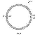
- FIG. 5is a bottom plan view of the container of FIG. 2;
- FIG. 6is a front elevational view of the inlet channel portion of the fluid dispenser of FIG. 1;
- FIG. 7is a left side elevational view of the inlet channel portion of FIG. 6;
- FIG. 8is a right side elevational view of the inlet channel portion of FIG. 6;
- FIG. 9is a top plan view of the inlet channel portion of FIG. 6;
- FIG. 10is a bottom plan view of the inlet channel portion of FIG. 6;
- FIG. 11is a front elevational view of the outlet channel portion of the fluid dispenser of FIG. 1;
- FIG. 12is a left side elevational view of the outlet channel portion of FIG. 11;
- FIG. 13is a right side elevational view of the outlet channel portion of FIG. 11;
- FIG. 14is a top plan view of the outlet channel portion of FIG. 11;
- FIG. 15is a bottom plan view of the outlet channel portion of FIG. 11;
- FIG. 16is a front elevational view of the primary flow member of the fluid dispenser of FIG. 1;
- FIG. 17is a top plan view of the primary flow member of FIG. 16 .
- the present inventionis directed to a fluid dispenser.
- the fluid dispenseris used to inject landscape maintenance fluids, such as fertilizers, herbicides, and pesticides, directly into the mainstream of an irrigation system.
- the dispenseris installed between the antisiphon valve and the irrigation heads.
- One dispensermay be installed as a dedicated unit for each irrigation system.
- the dispensing systemoperates by shunting a portion of the main irrigation water stream through a bypass to the dispenser containing the product to be dispensed.
- the waterdilutes the product to be applied, and is injected back into the main irrigation stream by the back pressure of the irrigation system and the venturi action caused by the restriction in the main irrigation stream adjacent to the orifice from the dispenser outlet back into the main irrigation channel.
- FIG. 1shows a fluid dispenser 10 having a container 12 , an inlet channel portion 14 coupled to an inlet side of the container 12 , an outlet channel portion 16 coupled to an outlet side of the container 12 , a container cap 18 coupled to the top of the container 12 , and a primary flow member 20 coupled to the bottom of the container 12 .
- the primary flow member 20includes a main irrigation stream flowing from an inlet port 21 to an outlet port 22 .
- An O-ring 23is disposed at the connection between the container 12 and the container cap 18 to provide a seal therebetween.
- a check ball 24 and a check ball retainer 26are disposed at the top of the container 12 and coupled with the container cap 18 to form a check valve, as discussed in more detail below.
- the container 12includes an inlet portion 32 with an inlet orifice 34 disposed near the top of the container 12 .
- the inlet channel portion 14is connected to the inlet portion 32 to form an inlet flow channel.
- the container 12includes an outlet portion 36 with an outlet orifice 38 disposed near the bottom of the container 12 .
- the outlet channel portion 16is connected to the outlet portion 36 to form an outlet flow channel.
- the container 12has a filling capacity as defined by the locations of the inlet and outlet orifices and channels. For example, a typical container 12 may have a filling capacity of about 16 oz of liquid.
- the container 12further includes a threaded top 40 .
- the inlet channel formed by coupling the inlet channel portion 14 to the inlet portion 32 of the container 12provides a path for the pressurized irrigation water to enter the container 12 and dilute the product in the container 12 to be dispensed.
- the inlet channel portion 14is a shell structure that includes an open bottom 42 coupled with an orifice 44 of the primary flow member 20 for receiving the irrigation water.
- the outlet channel formed by coupling the outlet channel portion 16 to the outlet portion 36 of the container 12provides a path for the diluted fluid to be dispensed into the main irrigation stream between the inlet port 21 and the outlet port 22 in the primary flow member 20 .
- the outlet channel portion 16includes an internal flow path 50 having an upper end 52 connected to the outlet channel formed by coupling the outlet channel portion 16 to the outlet portion 36 , and a lower end 54 mated with an orifice 56 of the primary flow member 20 .
- the pressurized fluid from the container 12is forced through the outlet orifice 38 into the outlet channel until it reaches the top of the outlet channel portion 16 , and then via the upper end 52 through the internal flow path 50 down through the orifice 56 back into the main irrigation stream in the primary flow member 20 .
- the fluid flow in the main irrigation streamis reduced or terminated and the pressure drops.
- the fluidceases to be diverted to the container, and the main irrigation stream drains.
- the ventopens, and the atmospheric pressure and the configuration of the filled outlet channel cause a siphon action to continue drawing fluid from the container 12 into the stream via the orifice 56 . This siphoning of the fluid from the container 12 continues until the container 12 is empty.
- Both the inlet flow path (via the inlet orifice 34 ) and the outlet flow path (via the top end 52 of the internal flow path 50 ) for the container 12employ an up-and-over design that permits filling the container 12 without spillover into the irrigation system, and evacuation of the fluid from the container by siphoning after each use.
- the container 12 , inlet channel portion 14 , and outlet channel portion 16may be made of PVC, ABS plastic, or the like.
- the inlet channel portion 14 and outlet channel portion 16can be connected to the inlet portion 32 and the outlet portion 36 , respectively, of the container 12 by any suitable methods, such as gluing, bonding, and the like.
- the primary flow member 20is bonded to the container assembly comprised of the container 12 , inlet channel portion 14 , and outlet channel portion 16 . Additional views of the primary flow member 20 are shown in FIGS. 16 and 17.
- the venturi action flow restriction 59 in the main irrigation stream as described aboveis shown in FIGS. 16 and 17, which is adjacent to and upstream of the orifice 56 of the primary flow member 20 .
- the primary flow member 20may be made of PVC, ABS plastic, or the like.
- the main water pipemay be installed into the irrigation system, for example, by gluing with PVC slip fittings or by a slip fit repair union.
- the container cap 18includes internal threads 60 for mating with the threaded top 40 of the container 12 , as shown in FIG. 1 .
- the cap 18is sealed to the container 12 with the O-ring 23 or other sealing member.
- the capincludes a valve seat 64 .
- a check valveis formed by the valve seat 64 , the check ball 24 and the check ball retainer 26 .
- the check ball 24may be made of nylon.
- the check ball retainer 26has a center hole that allows pressure to seat the check ball 24 .
- the check balldrops from the valve seat 64 to the check ball retainer 26 which is bonded to the container cap 18 , allowing air to enter the container 12 through the vent cap 66 while the remaining fluid is siphoned from the container 12 to the main irrigation channel of the primary flow member 20 .
- the vent cap 66contains a through hole which allows cleaning with a pipe cleaner.
- the dispenser 10is filled by removing the container cap 18 and adding the desired amount of product such as fertilizer or herbicide to be dispensed.
- the amountmay be determined by calculating the product weight per lawn area to be applied.
- water from the main irrigation streamflows through the primary flow member 20 as shown in FIG. 1 .
- the dispenser 10shunts a portion of the water from the main irrigation stream via the orifice 44 and through a bypass inlet channel formed by the inlet channel portion 14 to the container 12 . This diverted water fills the container 12 and dilutes the product in the container 12 to be applied.
- the back pressure of the irrigation systempressurizes the container 12 , and forces the diluted product to be injected into the irrigation system through the outlet channel formed by the outlet channel portion 16 and the orifice 56 .
- the bypass to the dispenser container 12does not impose any restrictions to the system water flow.
- the dispenser 10requires no outside power to operate.
- the dispenser 10is self-cleaning in that product dilution is sustained to about 100% (or pure water) when the product application is complete.
- the dispenser 10is evacuated automatically by siphoning the remaining fluid through the outlet channel via the orifice 56 .
- the configuration of the outlet channelcauses the siphon action as soon as the system back pressure is removed.
- the dispenser 10is installed in the irrigation system between the antisiphon valve and the irrigation heads.
- the dispenser 10may be installed in new systems using slip connectors, or in existing systems using slip/slip repair couplings.
- the dispenser 10may be installed above ground or partially buried.
- the size of the dispenser 10may vary depending on the application, ranging from a small unit for home use or a commercial size for use in larger areas such as golf courses, parks, farms, and the like.
- the filling of the container 12 with products to be dispensedmay be performed manually, or may be done automatically from selectable external sources in a fully automatic version, at times coordinated with a normal automatic irrigation system.
Landscapes
- Life Sciences & Earth Sciences (AREA)
- Chemical & Material Sciences (AREA)
- Chemical Kinetics & Catalysis (AREA)
- Engineering & Computer Science (AREA)
- Environmental Sciences (AREA)
- Water Supply & Treatment (AREA)
- Soil Sciences (AREA)
- Insects & Arthropods (AREA)
- Pest Control & Pesticides (AREA)
- Wood Science & Technology (AREA)
- Zoology (AREA)
- Nozzles (AREA)
Abstract
Description
Claims (23)
Priority Applications (1)
| Application Number | Priority Date | Filing Date | Title |
|---|---|---|---|
| US09/970,508US6722527B1 (en) | 2001-10-03 | 2001-10-03 | Irrigation fluid dispenser |
Applications Claiming Priority (1)
| Application Number | Priority Date | Filing Date | Title |
|---|---|---|---|
| US09/970,508US6722527B1 (en) | 2001-10-03 | 2001-10-03 | Irrigation fluid dispenser |
Publications (1)
| Publication Number | Publication Date |
|---|---|
| US6722527B1true US6722527B1 (en) | 2004-04-20 |
Family
ID=32070311
Family Applications (1)
| Application Number | Title | Priority Date | Filing Date |
|---|---|---|---|
| US09/970,508Expired - LifetimeUS6722527B1 (en) | 2001-10-03 | 2001-10-03 | Irrigation fluid dispenser |
Country Status (1)
| Country | Link |
|---|---|
| US (1) | US6722527B1 (en) |
Cited By (24)
| Publication number | Priority date | Publication date | Assignee | Title |
|---|---|---|---|---|
| US20060144244A1 (en)* | 2004-02-13 | 2006-07-06 | Intelligent Coffee Company, Llc | Liquid concentrate/extract beverage dispenser with replaceable concentrate/extract cartridge |
| US20080173705A1 (en)* | 2004-02-13 | 2008-07-24 | Intelligent Coffee Company, Llc | Liquid dispensing system |
| US20090119985A1 (en)* | 2007-11-10 | 2009-05-14 | Theo Duncan | Liquid Fertilizer, Weed Killer, and Pesticide Application Device Using Exchangeable Containers Connected to an Irrigation System |
| US20090120960A1 (en)* | 2008-05-15 | 2009-05-14 | Schroeder Industries, Inc. D/B/A Schroeder America | System for identifying fluid pathways through a fluid carrying device |
| US7614524B2 (en) | 2004-02-13 | 2009-11-10 | Intelligent Coffee Company, Llc | Liquid concentrate/extract beverage dispenser with replaceable concentrate/extract cartridge |
| US20090283543A1 (en)* | 2008-05-15 | 2009-11-19 | Schroeder Industries, Inc. D/B/A Schroeder America | Flow Control and Manifold Assembly |
| US20100187258A1 (en)* | 2009-01-27 | 2010-07-29 | Schroeder Industries, Inc. D/B/A Schroeder America | Post-mix dispenser assembly |
| US20110011108A1 (en)* | 2009-03-03 | 2011-01-20 | Schroeder Industries, Inc. | Microprocessor-Controlled Beverage Dispenser |
| US20110042415A1 (en)* | 2009-08-21 | 2011-02-24 | Schroeder Industries, Inc. D/B/A Schroeder America | Beverage dispensing apparatus |
| US20110084096A1 (en)* | 2009-10-12 | 2011-04-14 | Schroeder Industries, Inc. D/B/A Schroeder America | Beverage dispensing system having a cold plate and recirculating pump |
| US20110107918A1 (en)* | 2009-11-11 | 2011-05-12 | David Santy | Post-mix dispenser assembly |
| US20110174838A1 (en)* | 2010-01-15 | 2011-07-21 | Schroeder A A Jud | Retainer clip and fitting assembly for secure engagement with a fluid bearing device |
| USD646936S1 (en)* | 2009-11-04 | 2011-10-18 | Kennedy Dennis W | Fertilizer mixer and dispenser |
| US8387829B2 (en) | 2007-10-01 | 2013-03-05 | Schroeder Industries, Inc. | Nozzle assembly for a bar gun |
| US8418888B2 (en) | 2007-10-01 | 2013-04-16 | Schroeder Industries, Inc. | Backing plate assembly for a bar gun |
| USD697753S1 (en) | 2012-07-02 | 2014-01-21 | Schroeder Industries, Inc. | Bar gun |
| USD699592S1 (en)* | 2011-10-11 | 2014-02-18 | Taejoon Pharm. Co., Ltd. | Dispensing container |
| US20140150335A1 (en)* | 2007-02-13 | 2014-06-05 | Fram Group Ip Llc | Additive dispersing filter and method |
| US8770442B2 (en) | 2010-06-04 | 2014-07-08 | Schroeder Industries, Inc. | O-ring retainer for valve stem |
| US8881958B2 (en) | 2009-12-16 | 2014-11-11 | Intelligent Coffee Company, Llc | Fluid dose-measuring device |
| US8938987B2 (en) | 2010-09-16 | 2015-01-27 | Schroeder Industries, Inc. | Table top water dispenser having a refrigerator-cooled cold plate |
| CN105144955A (en)* | 2015-07-31 | 2015-12-16 | 潍坊友容实业有限公司 | Photovoltaic fertilizing apparatus for moistube-irrigation |
| US9376303B2 (en) | 2010-03-09 | 2016-06-28 | Cleland Sales Corp. | Temperature-controlled beverage dispenser |
| USD786616S1 (en) | 2012-07-02 | 2017-05-16 | Sam Brown | Bar gun |
Citations (4)
| Publication number | Priority date | Publication date | Assignee | Title |
|---|---|---|---|---|
| US1497271A (en)* | 1922-07-18 | 1924-06-10 | Harrison Ole | Automobile washing apparatus |
| US3195985A (en)* | 1962-07-10 | 1965-07-20 | Water Consultants Corp | Chemical feeder |
| US5364030A (en)* | 1993-07-29 | 1994-11-15 | Murdock James L | Solution injector for underground sprinkler systems |
| US5823430A (en)* | 1997-01-10 | 1998-10-20 | Clark, Jr.; George Donald | Automatic fertilizing apparatus |
- 2001
- 2001-10-03USUS09/970,508patent/US6722527B1/ennot_activeExpired - Lifetime
Patent Citations (4)
| Publication number | Priority date | Publication date | Assignee | Title |
|---|---|---|---|---|
| US1497271A (en)* | 1922-07-18 | 1924-06-10 | Harrison Ole | Automobile washing apparatus |
| US3195985A (en)* | 1962-07-10 | 1965-07-20 | Water Consultants Corp | Chemical feeder |
| US5364030A (en)* | 1993-07-29 | 1994-11-15 | Murdock James L | Solution injector for underground sprinkler systems |
| US5823430A (en)* | 1997-01-10 | 1998-10-20 | Clark, Jr.; George Donald | Automatic fertilizing apparatus |
Cited By (42)
| Publication number | Priority date | Publication date | Assignee | Title |
|---|---|---|---|---|
| US20060144244A1 (en)* | 2004-02-13 | 2006-07-06 | Intelligent Coffee Company, Llc | Liquid concentrate/extract beverage dispenser with replaceable concentrate/extract cartridge |
| US20080173705A1 (en)* | 2004-02-13 | 2008-07-24 | Intelligent Coffee Company, Llc | Liquid dispensing system |
| US8091735B2 (en) | 2004-02-13 | 2012-01-10 | Intelligent Coffee Company, Llc | Liquid dispensing system |
| US8757227B2 (en) | 2004-02-13 | 2014-06-24 | Intelligent Coffee Company, Llc | Replaceable concentrate/extract cartridge for a liquid concentrate/extract beverage dispenser |
| US7614524B2 (en) | 2004-02-13 | 2009-11-10 | Intelligent Coffee Company, Llc | Liquid concentrate/extract beverage dispenser with replaceable concentrate/extract cartridge |
| US7828020B2 (en) | 2004-02-13 | 2010-11-09 | Intelligent Coffee Company, Llc | Replaceable concentrate/extract cartridge for a liquid concentrate/extract beverage dispenser |
| US7651015B2 (en) | 2004-02-13 | 2010-01-26 | Intelligent Coffee Company, Llc | Liquid concentrate/extract beverage dispenser with replaceable concentrate/extract cartridge |
| US20100089944A1 (en)* | 2004-02-13 | 2010-04-15 | Intelligent Coffee Company, Llc | Replaceable concentrate/extract cartridge for a liquid concentrate/extract beverage dispenser |
| US20090057341A1 (en)* | 2005-01-07 | 2009-03-05 | Intelligent Coffee Company, Llc | Liquid concentrate/extract beverage dispenser with replaceable concentrate/extract cartridge |
| US8210396B2 (en) | 2005-01-07 | 2012-07-03 | Intelligent Coffee Company, Llc | Liquid concentrate/extract beverage dispenser with replaceable concentrate/extract cartridge |
| US8800820B2 (en) | 2005-11-03 | 2014-08-12 | Intelligent Coffee Company, Llc | Liquid concentrate/extract beverage dispenser with replaceable concentrate/extract cartridge |
| US9155417B2 (en) | 2005-11-03 | 2015-10-13 | Intelligent Coffee Company, Llc | Liquid concentrate/extract beverage dispenser with replaceable concentrate/extract cartridge |
| US9539531B2 (en)* | 2007-02-13 | 2017-01-10 | Fram Group IP, LLC | Additive dispersing filter and method |
| US20140150335A1 (en)* | 2007-02-13 | 2014-06-05 | Fram Group Ip Llc | Additive dispersing filter and method |
| US8418888B2 (en) | 2007-10-01 | 2013-04-16 | Schroeder Industries, Inc. | Backing plate assembly for a bar gun |
| US8387829B2 (en) | 2007-10-01 | 2013-03-05 | Schroeder Industries, Inc. | Nozzle assembly for a bar gun |
| WO2009058839A1 (en)* | 2007-10-29 | 2009-05-07 | Intelligent Coffee Company, Llc | Liquid dispensing system |
| US20090119985A1 (en)* | 2007-11-10 | 2009-05-14 | Theo Duncan | Liquid Fertilizer, Weed Killer, and Pesticide Application Device Using Exchangeable Containers Connected to an Irrigation System |
| US20090283543A1 (en)* | 2008-05-15 | 2009-11-19 | Schroeder Industries, Inc. D/B/A Schroeder America | Flow Control and Manifold Assembly |
| US8807395B2 (en) | 2008-05-15 | 2014-08-19 | Schroeder Industries, Inc. | System for identifying fluid pathways through a fluid carrying device |
| US20090120960A1 (en)* | 2008-05-15 | 2009-05-14 | Schroeder Industries, Inc. D/B/A Schroeder America | System for identifying fluid pathways through a fluid carrying device |
| US8336736B2 (en) | 2008-05-15 | 2012-12-25 | Schroeder Industries, Inc. | Flow control and manifold assembly |
| US20100187258A1 (en)* | 2009-01-27 | 2010-07-29 | Schroeder Industries, Inc. D/B/A Schroeder America | Post-mix dispenser assembly |
| US9873605B2 (en) | 2009-01-27 | 2018-01-23 | Schroeder Industries, Inc. | Post-mix dispenser assembly |
| US9243830B2 (en) | 2009-03-03 | 2016-01-26 | Cleland Sales Corporation | Microprocessor-controlled beverage dispenser |
| US20110011108A1 (en)* | 2009-03-03 | 2011-01-20 | Schroeder Industries, Inc. | Microprocessor-Controlled Beverage Dispenser |
| US8814003B2 (en) | 2009-08-21 | 2014-08-26 | Schroeder Industries, Inc. | Beverage dispensing apparatus |
| US20110042415A1 (en)* | 2009-08-21 | 2011-02-24 | Schroeder Industries, Inc. D/B/A Schroeder America | Beverage dispensing apparatus |
| US20110084096A1 (en)* | 2009-10-12 | 2011-04-14 | Schroeder Industries, Inc. D/B/A Schroeder America | Beverage dispensing system having a cold plate and recirculating pump |
| US8944290B2 (en) | 2009-10-12 | 2015-02-03 | Schroeder Industries, Inc. | Beverage dispensing system having a cold plate and recirculating pump |
| USD646936S1 (en)* | 2009-11-04 | 2011-10-18 | Kennedy Dennis W | Fertilizer mixer and dispenser |
| US20110107918A1 (en)* | 2009-11-11 | 2011-05-12 | David Santy | Post-mix dispenser assembly |
| US8881958B2 (en) | 2009-12-16 | 2014-11-11 | Intelligent Coffee Company, Llc | Fluid dose-measuring device |
| US20110174838A1 (en)* | 2010-01-15 | 2011-07-21 | Schroeder A A Jud | Retainer clip and fitting assembly for secure engagement with a fluid bearing device |
| US9376303B2 (en) | 2010-03-09 | 2016-06-28 | Cleland Sales Corp. | Temperature-controlled beverage dispenser |
| US8770442B2 (en) | 2010-06-04 | 2014-07-08 | Schroeder Industries, Inc. | O-ring retainer for valve stem |
| US8938987B2 (en) | 2010-09-16 | 2015-01-27 | Schroeder Industries, Inc. | Table top water dispenser having a refrigerator-cooled cold plate |
| USD699592S1 (en)* | 2011-10-11 | 2014-02-18 | Taejoon Pharm. Co., Ltd. | Dispensing container |
| USD697753S1 (en) | 2012-07-02 | 2014-01-21 | Schroeder Industries, Inc. | Bar gun |
| USD786616S1 (en) | 2012-07-02 | 2017-05-16 | Sam Brown | Bar gun |
| CN105144955A (en)* | 2015-07-31 | 2015-12-16 | 潍坊友容实业有限公司 | Photovoltaic fertilizing apparatus for moistube-irrigation |
| CN105144955B (en)* | 2015-07-31 | 2017-09-15 | 潍坊友容实业有限公司 | A kind of micro- profit irrigation photovoltaic fertilizer apparatus |
Similar Documents
| Publication | Publication Date | Title |
|---|---|---|
| US6722527B1 (en) | Irrigation fluid dispenser | |
| US6659128B2 (en) | Fluid injection with vent/proportioner ports | |
| CN201238547Y (en) | Automatic agricultural chemicals mixer with variable atomization | |
| EP2502490B1 (en) | System for spraying liquid for agricultural purposes and method for spraying | |
| US5364030A (en) | Solution injector for underground sprinkler systems | |
| CA2591731C (en) | Chemical application apparatus for sprinkler systems | |
| US9545642B2 (en) | Chemical dispenser | |
| US10834868B2 (en) | Efficient injection and mixing of chemicals into a fluid delivery system | |
| US20120255973A1 (en) | Refillable chemical reservoir system for trigger sprayer | |
| CA3019795A1 (en) | Mix on demand sprayer | |
| US10413922B2 (en) | Mix on demand sprayer with external by-pass circuit | |
| US11104567B2 (en) | Ultra high ratio liquid delivery system | |
| EP2916645B1 (en) | Fluid injection system | |
| US20210347624A1 (en) | Ultra high ratio liquid delivery system | |
| US4846214A (en) | Fluid additive injector | |
| US5188294A (en) | Apparatus for dispensing/applying a material | |
| CN109379962A (en) | A kind of preceding fertilizer apparatus of water-fertilizer integral pump | |
| US4856683A (en) | Herbicide dispenser | |
| US20070215722A1 (en) | Fertilizer dispensing device | |
| GB2447377A (en) | Liquid chemical dispenser for an irrigation system | |
| US6969011B2 (en) | Chemical additive dispensing device for use with a station of an irrigation system | |
| US20200061654A1 (en) | Fluid control assembly for mix-on-demand sprayer | |
| JPS5811975B2 (en) | What's new? | |
| CA3036038A1 (en) | Mix on demand sprayer with external by-pass circuit | |
| CZ244599A3 (en) | Apparatus for low-pressure control of liquid flow from pipe openings |
Legal Events
| Date | Code | Title | Description |
|---|---|---|---|
| AS | Assignment | Owner name:AUTOMATIC BAR CONTROLS, INC., CALIFORNIA Free format text:ASSIGNMENT OF ASSIGNORS INTEREST;ASSIGNOR:KRAUSS, LARRY;REEL/FRAME:012239/0795 Effective date:20010927 | |
| AS | Assignment | Owner name:LASALLE BANK NATIONAL ASSOCIATION, AS AGENT, ILLIN Free format text:SECURITY AGREEMENT;ASSIGNOR:AUTOMATIC BAR CONTROLS, INC.;REEL/FRAME:013146/0790 Effective date:20020719 | |
| STCF | Information on status: patent grant | Free format text:PATENTED CASE | |
| CC | Certificate of correction | ||
| AS | Assignment | Owner name:AUTOMATIC BAR CONTROLS, INC., CALIFORNIA Free format text:RELEASE AND REASSIGNMENT;ASSIGNOR:LASALLE BANK NATIONAL ASSOCIATION;REEL/FRAME:016290/0038 Effective date:20050630 | |
| AS | Assignment | Owner name:ANTARES CAPITAL CORPORATION, AS AGENT, ILLINOIS Free format text:SECURITY AGREEMENT;ASSIGNOR:AUTOMATIC BAR CONTROLS, INC.;REEL/FRAME:016784/0060 Effective date:20050630 Owner name:ANTARES CAPITAL CORPORATION, AS AGENT, ILLINOIS Free format text:ASSIGNMENT OF ASSIGNORS INTEREST;ASSIGNOR:AUTOMATIC BAR CONTROLS, INC.;REEL/FRAME:016784/0060 Effective date:20050630 | |
| AS | Assignment | Owner name:ANTARES CAPITAL CORPORATION, AS AGENT, ILLINOIS Free format text:SECURITY AGREEMENT;ASSIGNOR:AUTOMATIC BAR CONTROLS, INC.;REEL/FRAME:016610/0142 Effective date:20050630 | |
| AS | Assignment | Owner name:AMERICA CAPITAL STRATEGIES, INC., MARYLAND Free format text:RELEASE AND REASSIGNMENT;ASSIGNORS:ACAS ACQUISITIONS (AUTOMATIC BAR CONTROLS, INC.);AUTOMATIC HOLDING CORPORATION;AUTOMATIC BAR CONTROLS, INC.;REEL/FRAME:016621/0764 Effective date:20050630 | |
| REFU | Refund | Free format text:REFUND - PAYMENT OF MAINTENANCE FEE, 4TH YEAR, LARGE ENTITY (ORIGINAL EVENT CODE: R1551); ENTITY STATUS OF PATENT OWNER: LARGE ENTITY | |
| FPAY | Fee payment | Year of fee payment:4 | |
| SULP | Surcharge for late payment | ||
| AS | Assignment | Owner name:ANTARES CAPITAL CORPORATION, AS ADMINISTRATIVE AGE Free format text:SECURITY AGREEMENT;ASSIGNOR:AUTOMATIC BAR CONTROLS, INC.;REEL/FRAME:026068/0963 Effective date:20110401 | |
| FPAY | Fee payment | Year of fee payment:8 | |
| AS | Assignment | Owner name:AUTOMATIC HOLDING CORPORATION, CALIFORNIA Free format text:CORRECTIVE ASSIGNMENT TO CORRECT THE IDENTITY OF THE CONVEYING AND RECEIVING PARTY DATA PREVIOUSLY RECORDED ON REEL 016621 FRAME 0764. ASSIGNOR(S) HEREBY CONFIRMS THE IDENTITY OF THE CONVEYING PARTY AND RECEIVING PARTIES WITHIN FIRST PAGE OF ASSIGNMENT;ASSIGNOR:AMERICA CAPITAL STRATEGIES, INC.;REEL/FRAME:031828/0657 Effective date:20050630 Owner name:AUTOMATIC BAR CONTROLS, INC., CALIFORNIA Free format text:CORRECTIVE ASSIGNMENT TO CORRECT THE IDENTITY OF THE CONVEYING AND RECEIVING PARTY DATA PREVIOUSLY RECORDED ON REEL 016621 FRAME 0764. ASSIGNOR(S) HEREBY CONFIRMS THE IDENTITY OF THE CONVEYING PARTY AND RECEIVING PARTIES WITHIN FIRST PAGE OF ASSIGNMENT;ASSIGNOR:AMERICA CAPITAL STRATEGIES, INC.;REEL/FRAME:031828/0657 Effective date:20050630 Owner name:ACAS ACQUISITIONS (AUTOMATIC BAR CONTROLS, INC.), Free format text:CORRECTIVE ASSIGNMENT TO CORRECT THE IDENTITY OF THE CONVEYING AND RECEIVING PARTY DATA PREVIOUSLY RECORDED ON REEL 016621 FRAME 0764. ASSIGNOR(S) HEREBY CONFIRMS THE IDENTITY OF THE CONVEYING PARTY AND RECEIVING PARTIES WITHIN FIRST PAGE OF ASSIGNMENT;ASSIGNOR:AMERICA CAPITAL STRATEGIES, INC.;REEL/FRAME:031828/0657 Effective date:20050630 | |
| FPAY | Fee payment | Year of fee payment:12 |