US6722404B2 - Syringe bandolier with control feature - Google Patents
Syringe bandolier with control featureDownload PDFInfo
- Publication number
- US6722404B2 US6722404B2US10/001,244US124401AUS6722404B2US 6722404 B2US6722404 B2US 6722404B2US 124401 AUS124401 AUS 124401AUS 6722404 B2US6722404 B2US 6722404B2
- Authority
- US
- United States
- Prior art keywords
- bandolier
- syringes
- web
- feature
- control
- Prior art date
- Legal status (The legal status is an assumption and is not a legal conclusion. Google has not performed a legal analysis and makes no representation as to the accuracy of the status listed.)
- Expired - Fee Related, expires
Links
- 238000001514detection methodMethods0.000claimsdescription84
- 230000003287optical effectEffects0.000claimsdescription29
- 238000004891communicationMethods0.000claimsdescription9
- 239000012530fluidSubstances0.000claimsdescription7
- 230000004044responseEffects0.000claimsdescription3
- 238000007599dischargingMethods0.000claims1
- 239000002985plastic filmSubstances0.000claims1
- 239000003814drugSubstances0.000abstractdescription35
- 239000000126substanceSubstances0.000abstractdescription6
- 239000012780transparent materialSubstances0.000abstractdescription2
- 230000007246mechanismEffects0.000description47
- 238000000034methodMethods0.000description8
- 238000003860storageMethods0.000description6
- 239000003085diluting agentSubstances0.000description5
- 239000000463materialSubstances0.000description5
- 230000008569processEffects0.000description5
- 238000002360preparation methodMethods0.000description4
- 230000009471actionEffects0.000description2
- 238000010586diagramMethods0.000description2
- 238000007689inspectionMethods0.000description2
- 238000004519manufacturing processMethods0.000description2
- 238000005259measurementMethods0.000description2
- 239000000853adhesiveSubstances0.000description1
- 230000001070adhesive effectEffects0.000description1
- 230000008901benefitEffects0.000description1
- 239000008280bloodSubstances0.000description1
- 210000004369bloodAnatomy0.000description1
- 238000009530blood pressure measurementMethods0.000description1
- 238000012790confirmationMethods0.000description1
- 238000010276constructionMethods0.000description1
- 230000007812deficiencyEffects0.000description1
- 238000005516engineering processMethods0.000description1
- 238000001990intravenous administrationMethods0.000description1
- 239000000203mixtureSubstances0.000description1
- 238000007639printingMethods0.000description1
- 238000012545processingMethods0.000description1
- 230000001105regulatory effectEffects0.000description1
- 230000011664signalingEffects0.000description1
Images


Classifications
- B—PERFORMING OPERATIONS; TRANSPORTING
- B65—CONVEYING; PACKING; STORING; HANDLING THIN OR FILAMENTARY MATERIAL
- B65B—MACHINES, APPARATUS OR DEVICES FOR, OR METHODS OF, PACKAGING ARTICLES OR MATERIALS; UNPACKING
- B65B3/00—Packaging plastic material, semiliquids, liquids or mixed solids and liquids, in individual containers or receptacles, e.g. bags, sacks, boxes, cartons, cans, or jars
- B65B3/003—Filling medical containers such as ampoules, vials, syringes or the like
- B—PERFORMING OPERATIONS; TRANSPORTING
- B65—CONVEYING; PACKING; STORING; HANDLING THIN OR FILAMENTARY MATERIAL
- B65B—MACHINES, APPARATUS OR DEVICES FOR, OR METHODS OF, PACKAGING ARTICLES OR MATERIALS; UNPACKING
- B65B15/00—Attaching articles to cards, sheets, strings, webs, or other carriers
- B65B15/04—Attaching a series of articles, e.g. small electrical components, to a continuous web
- B—PERFORMING OPERATIONS; TRANSPORTING
- B65—CONVEYING; PACKING; STORING; HANDLING THIN OR FILAMENTARY MATERIAL
- B65B—MACHINES, APPARATUS OR DEVICES FOR, OR METHODS OF, PACKAGING ARTICLES OR MATERIALS; UNPACKING
- B65B17/00—Other machines, apparatus, or methods for packaging articles or materials
- B65B17/02—Joining articles, e.g. cans, directly to each other for convenience of storage, transport, or handling
- B—PERFORMING OPERATIONS; TRANSPORTING
- B65—CONVEYING; PACKING; STORING; HANDLING THIN OR FILAMENTARY MATERIAL
- B65B—MACHINES, APPARATUS OR DEVICES FOR, OR METHODS OF, PACKAGING ARTICLES OR MATERIALS; UNPACKING
- B65B57/00—Automatic control, checking, warning, or safety devices
- B65B57/02—Automatic control, checking, warning, or safety devices responsive to absence, presence, abnormal feed, or misplacement of binding or wrapping material, containers, or packages
Definitions
- the present inventionrelates generally to medical equipment, and more particularly, to unit dose, disposable syringes that are used for the delivery of fluids into an object, such as a human body or an animal's body.
- syringesare in widespread use for a number of different types of applications.
- syringesare used not only to withdraw a fluid (e.g., blood) from a patient but also to administer a medicament to a patient.
- a cap or the likeis removed from the syringe and a unit does of the medicament is carefully measured and then injected or otherwise disposed within the syringe.
- one type of exemplary automated systemoperates as a syringe filling apparatus that receives user inputted information, such as the type of medicament, the volume of the medicament and any mixing instructions, etc. The system then uses this inputted information to disperse the correct medicament into the syringe up to the inputted volume.
- the medicament that is to be delivered to the patientincludes more than one pharmaceutical substance.
- the medicamentcan be a mixture of several components, such as several pharmaceutical substances.
- syringesare often used as the carrier means for transporting and delivering the medicament to the patient, it is advantageous for these automated systems to be tailored to accept syringes.
- syringesThere are a vast number of different types of syringes that are commercially available and some of those available may be improper for use with a given type of automated system.
- the shape and/or dimensions of the syringemay prevent one syringe type from being used in a given automated system and can even cause damage due to jamming of the syringes as they are fed into the automated system.
- a bandolier of syringes for use in an automated syringe handling systemis provided.
- the automated syringe handling systemgenerally receives syringes and fills each syringe with a substance, such as a medicament.
- the syringe handling systemis a system that disperses one or more medicaments into the syringes in an automated manner.
- a bandolierincludes a web, e.g., a strip of transparent material, partially encapsulating bodies of syringes that are bound to the web at a prescribed interval.
- the bandolierincludes a control feature disposed within the prescribed interval and between the syringes with the control feature being different from the surrounding web.
- control featureis used in combination with a detection system that is configured to detect the control feature.
- a detection systemthat is configured to detect the control feature.
- a control system in accordance with this aspect of the inventionincludes an indexer configured to advance a syringe through the automated syringe handling system, a bandolier of syringes supplying syringes to the indexer, and a detection system including a detector positioned to detect the control feature on the bandolier and perform a prescribed operation in response to the detection or non-detection of the control feature.
- control featurecan also ensure that only syringes of the correct type are used with the automated syringe handling system.
- FIG. 1is a schematic diagram of an automated system for dispersing a medicament
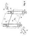
- FIG. 2is a side elevational view of a syringe bandolier according to one embodiment
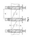
- FIG. 3is a top plan view of the syringe bandolier of FIG. 2;
- FIG. 4is a perspective view of the syringe bandolier of FIG. 1 used in combination with a detection mechanism;
- FIG. 5is a side elevational view of a syringe bandolier according to another embodiment
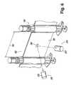
- FIG. 6is a perspective view of a syringe bandolier and a detection mechanism of another embodiment.
- FIG. 7is a perspective view of a syringe bandolier and a detection mechanism of yet another embodiment.
- FIG. 1is a schematic diagram illustrating one exemplary automated system, generally indicated at 10 , for the preparation of a medicament.
- the automated system 10is divided into a number of stations where a specific task is performed based on the automated system 10 receiving user input instructions, processing these instructions and then preparing unit doses of one or more medicaments in accordance with the instructions.
- the automated system 10includes a first station 20 where medicaments and other substances used in the preparation process are stored.
- the term “medicament”refers to a medicinal preparation for administration to a patient.
- the medicamentcan include one or more pharmaceutical substances and can also include non-pharmaceutical substances, such as a diluent, etc.
- the first station 20functions as a storage unit for storing one or medicaments, etc. under proper storage conditions.
- medicaments and the likeare stored in sealed containers, such as vials, that are labeled to clearly indicate the contents of each vial.
- a second station 30is a syringe storage station 130 that houses and stores a number of syringes. For example, up to 500 syringes or more can be disposed in the second station 30 for storage and later use.
- the station 30can be in the form of a bin or the like or any other type of structure than can hold a number of syringes.
- the system 10also includes a rotary apparatus 40 for advancing items to and from various stations of the system 10 .
- a number of the stationsare arranged circumferentially around the rotary apparatus 40 so that when an item is supported on, coupled to, or engaged by the rotary apparatus 40 at a first location and the rotary apparatus 40 is then advanced, the item is rotated to a next station where a different action occurs.
- One exemplary type of rotary apparatus 40is a multiple station cam-indexing dial that is adapted to perform material handling operations.
- the indexeris configured to have multiple stations positioned thereabout with individual nests for each station position.
- One syringeis held within one nest using any number of suitable techniques, including opposing spring-loaded fingers that act to clamp the syringe in its respective nest.
- the indexerpermits the rotary apparatus 40 to be advanced at specific intervals.
- the system 10also preferably includes a reading device (not shown) that is capable of reading a label disposed on the sealed container containing the medicament.
- the labelis read using any number of suitable reader/scanner devices, such as a bar code reader, etc., so as to confirm that the proper medicament has been selected from the storage unit of the first station 20 .
- Multiple readerscan be employed in the system at various locations to confirm the accuracy of the entire process.
- a safety cap or the likeis removed from the sealed container.
- the safety capis removed in a just-in-time for use manner on a deck of the automated system 10 .
- the system 10also preferably includes a station 50 for injecting a diluent into the medicament contained in the opened container and then subsequently mixing the medicament and the diluent.
- a station 60syringes are loaded into one of the nests of the rotary apparatus 40 .
- One syringeis loaded into one nest of the rotary apparatus 40 in which the syringe is securely held in place.
- the system 10preferably includes additional mechanisms for preparing the syringe for use, such as removing a tip cap and extending a plunger of the syringe.
- the medicament(with diluent) is withdrawn from the medicament's container and is then disposed into the syringe at station 65 .
- a cannulacan be inserted into the sealed container and the mixed medicament then aspirated into a cannula set.
- the cannulais then withdrawn from the container and positioned using the rotary apparatus 40 in line with (above, below, etc.) the syringe.
- the unit dose of the medicamentis then delivered to the syringe, as well as additional diluent if necessary or desired.
- the tip capis then placed back on the syringe.
- Another station 70prints and applies a label to the syringe and one of the readers can be used to verify that this label is placed in a correct location and the printing thereon is readable. Also, the reader can confirm that the label properly identifies the medicament that is contained in the syringe.
- the syringeis then unloaded from the rotary apparatus 40 at a station 80 and delivered to a predetermined location, such as a new order bin, a conveyor, a sorting device, or a reject bin. The delivery of the syringe can be accomplished using a standard conveyor or other type of apparatus.
- the robotic devicesare part of a computer based system that permits the user to simply enter a command and this causes the robotic devices to be driven under program control to any number of locations to perform prescribed tasks.
- the bandolier 100can be used with an automated system, such as the previously-described automated system 10 .
- the bandolier of syringes 100includes a number of syringes 110 spaced a predetermined distance from one another and attached to one another into a strip 120 .
- the syringes 110are traditional syringes with each having a body 112 , a plunger 114 that is slidably received in the body 112 , and a cap 116 at one end of the body 112 .
- the cap 116is preferably of a removable type and covers a syringe port that is used to receive and/or discharge fluid.
- the bandolier 100is formed so that the syringes 110 are held in place and at predetermined spaced intervals within the strip 120 by a first strip layer 130 and a second strip layer 140 .
- the syringes 110are disposed between the first and second strip layers 130 , 140 with the layers 130 , 140 being form fitted so that they are disposed intimately over the contours of the syringes 110 .
- syringessuch as syringes 110 , come in a number of different shapes and sizes; however, the above-mentioned components thereof are typically common to most syringe constructions.
- first and second strip layers 130 , 140can be formed of a plastic material.
- the bandolier 100can be assembled by first providing the first strip layer 130 , then disposing the syringes 110 at the desired predetermined intervals along the first strip layer 130 before then disposing the second strip layer 140 over the syringes 110 opposite the first strip layer 130 .
- first strip layer 130 , syringes 110 , and second strip layer 140are then subjected to a process for causing the first and second strip layers 130 , 140 to become in intimate contact with each other in the intervals between the syringes 110 and in intimate contact with the bodies of syringes 110 .
- One type of process for achieving such a resultinvolves the use of a vacuum type system that evacuates the air between the first and second strip layers 130 , 140 and causes the syringes 110 to be secured and held in the desired locations along the strip 120 .
- an adhesive or a heat weldcan be used between the first and second strip layers 130 , 140 for producing the final bandolier 100 .
- the strip 120is defined by an upper edge 121 and a lower edge 123 with each syringe 110 extending beyond both the upper edge 121 and the lower edge 123 . More specifically, the first and second strip layers 130 , 140 are positioned in the region of the syringe body 112 so that the layers 130 , 140 seal against this body portion 112 in the completed bandolier 100 . Because the syringes 110 bound to the strip 120 are spaced along the strip at predetermined locations, prescribed intervals 150 are formed between the syringes 110 . In other words, between next adjacent syringes 110 , one prescribed interval 150 is formed and consists of the first and second strip layers 130 , 140 sealed to one another. Preferably, the length of each prescribed interval 150 is the same along the length of the entire bandolier 100 .
- the bandolier 100has a control feature, generally indicated at 160 , incorporated therein to ensure that the bandolier 100 is properly aligned in a system that it is being used in, such as the automated system 10 , and also to ensure that the syringes 110 of the bandolier 100 have specifications, e.g., dimensions, that fall within the acceptable specifications of the system with which the bandolier 100 is being used.
- the control feature 160is formed in each prescribed interval 150 between next adjacent syringes 110 .
- the control feature 160is configured so that a detection mechanism, such as a reader or other type of similar device, can detect the presence or absence, as well as the location of the control feature 160 within the prescribed interval 150 .
- the control feature 160is an aperture formed in the prescribed interval 150 at a specific location thereof.
- the control feature 160can be in the form of an aperture having a square shape.
- the system 10typically includes a laminar flow of air about the stations and rotary apparatus 40 to ensure that the system 10 is clean and remains in a clean state during operation.
- a detection mechanism 170takes advantage of the presence of this laminar air flow by incorporating a nozzle 180 into the components providing the laminar air flow in the system 10 .
- the nozzle 180discharges a laminar air flow and if the bandolier 100 is precision fed into the system 10 , proper alignment of the control feature 160 results and hence the syringe 110 can be ascertained by having the laminar air flow directed toward the bandolier 100 at the same height as the height that the control feature 160 is formed in the prescribed interval 150 .
- the laminar air flowis in registration with the control feature 160 at select times when the aperture 160 and the laminar air flow align with one another.
- the laminar air flowsimply strikes the strip 120 and does not pass therethrough.
- the detection mechanism 170also includes a sensor 190 that is disposed on the opposite side of the bandolier 100 as compared to the nozzle 180 .
- the sensor 190is configured to detect the presence of the laminar air flow when the aperture and laminar air flow are in alignment.
- the sensor 190is of a type that detects the presence of the laminar air flow against the sensor 190 itself and in one embodiment, the sensor 190 is a pressure sensor.
- the laminar air flow and the control feature 160are in registration, the laminar air flow is permitted to flow cleanly through the aperture formed in the bandolier 100 and make contact with the sensor 190 .
- the sensor 190detects the presence of the laminar air flow and signals a controller (not shown) or the like of such detection.
- the controlleris integrated into the system 10 such that upon receiving this signal, the controller then signals other components, such as the rotary apparatus 40 , of the system 10 to advance the bandolier 100 a prescribed distance. It should be understood that the controller can respond to the pressure of the air flow through the control feature 160 or to a logical waveform resulting from the timing of air signals relative to periods without air signals (e.g., due to indexing of the bandolier 100 ).
- the bandolier 100is advanced the prescribed distance, another of the apertures (control feature) 160 is then axially aligned with the laminar air flow so long as the correct type of bandolier 100 for the system 10 is in place, the syringe orientation (up or down) is proper, and also the alignment of the bandolier 100 is proper.
- the distance between the control features 160corresponds to the distance that the bandolier 100 is advanced upon receiving the control signal from the detection mechanism 170 .
- the bandolier 100is continuously advanced because each time the detection mechanism 170 is in recognition with the control feature 160 , the bandolier 100 is advanced a distance that corresponds to the next control feature 160 being within a detection zone, thereby resulting in the detection mechanism 170 detecting the next control feature 160 and signaling the system 10 to further advance the bandolier 100 .
- the control feature 160ensures proper alignment of the bandolier 100 and also ensures that the proper type of bandolier 100 is being used as the system 10 is configured to stop advancing the bandolier 100 if the detection mechanism 170 fails to read the control feature 160 . For example, if the correct bandolier 100 is being used but the bandolier 100 becomes misaligned as it is being fed, the control feature 160 will not be in alignment with the nozzle 180 as the bandolier 100 is advanced.
- the detection mechanism 170is preferably configured so that it will only advance the bandolier 100 a predetermined distance without detecting the control feature 160 .
- the detection mechanism 170signals the controller or the like of the system 10 to stop advancement of the bandolier 100 .
- an error messageis generated at the same time the bandolier 100 is stopped. Manual inspection is then performed to locate the problem.
- the system 10is preferably a computer based system that receives user input.
- the usercan input the type of bandolier 100 that is being used in the system 10 .
- the useris asked to input and identify the bandolier 100 by its common characteristics.
- Syringes 110are commonly identified by their volume capacities and exemplary syringes that can be used with the system 10 , include 12 ml (intravenous) and 25 ml (oral) syringes.
- the userpreferably inputs the type of syringe (i.e., whether it is a 12 ml, 25 ml, or other size syringe) and then a microprocessor or the like will store this information and relay this information to the controller and detection mechanism 170 .
- a microprocessor or the likewill store this information and relay this information to the controller and detection mechanism 170 .
- the detection mechanism 170differentiate between the various different types of bandoliers 100 , several techniques can be used.
- control features 160formed in the prescribed interval 150 according to a distinct pattern that is recognized by a detection mechanism (not shown).
- One exemplary patternhas one control feature 160 formed on top of another control feature 161 with the one control feature 160 being in the location that is associated with a syringe of a first type (e.g., 12 ml) and with a syringe of a second type (e.g., 25 ml) when the one control feature 160 is read along with the other control feature 161 .
- the detection mechanismthus includes two nozzles and two sensors in this embodiment with one nozzle and one sensor for registration with the one control feature 160 and the other nozzle and sensor for registration with the other control feature 161 .
- the syringe storage station 130might be able to house multiple syringe sizes (e.g., smaller sizes than intended). If the detection mechanism 170 does not detect the control features 160 , 161 , the bandolier 100 is not advanced.
- the precise location of the control feature 160 within the prescribed interval 150can also be used to differentiate one bandolier type from another bandolier type.
- the detection mechanism 170can be driven by software such that the nozzle 180 and the sensor 190 are driven (see arrows A and B) to a prescribed coordinate location that corresponds to the type of bandolier 100 that is inputted into the system 10 . This prescribed coordinate location is in registration with the control feature 160 that corresponds to the bandolier type inputted.
- the detection mechanism 170(nozzle 180 and sensor 190 ) is moved to a first coordinate location (shown), while the detection mechanism 170 is driven to a second coordinate location (not shown) if the user enters that a 12 ml bandolier 100 is being used.
- control feature 200is illustrated and generally indicated at 200 along with a detection mechanism 210 that is configured to be used with the control feature 200 .
- the control feature 200is an optical feature that is used as part of an optical detection mechanism 210 .
- the optical feature 200is formed in the prescribed region 150 of the bandolier 100 with next adjacent optical features 200 being spaced a prescribed distance from one another.
- the detection mechanism 210is a detection mechanism that optically detects the presence of the optical feature 200 when the optical feature 200 is in proper registration with an optical detector 220 .
- the optical detection mechanism 210can include an optical detector 220 that faces the bandolier 100 as the bandolier 100 is advanced.
- the optical detector 220cooperates with a light source, such as a laser or LED 225 that also faces the bandolier 100 to detect the presence of the optical feature 200 .
- the light source and optical detectorare arranged relative to each other in accordance with Snell's Law of Reflection; however, the light source and detector can be arranged otherwise, such as normal to and facing the optical feature 200 .
- the feature 200can come in a number of different shapes and sizes.
- the optical detection mechanism 210operates essentially in the same manner as the detection mechanism 170 of FIG. 4 .
- the bandolier 100is only advanced if the optical detection mechanism 210 reads the optical sensor 200 . If the bandolier 100 is advanced a prescribed distance and the optical detection mechanism 210 does not read the optical sensor 200 , the advancement of the bandolier 100 is stopped. Accordingly, proper registration between the optical sensors 200 and the detection mechanism 210 is needed for the bandolier 100 to be continuously advanced.
- the control featureis a mark 230 that is formed within the prescribed interval 150 between spaced syringes 110 and a detection mechanism 240 is used for detecting the mark 230 .
- the mark 230can be any number of types of marks, including a printed mark that is formed on the surface of bandolier 100 .
- the detection mechanism 240is used to detect the mark 230 and if a detection is not made within a prescribed time interval or during advancement of the bandolier 100 over a prescribed distance, the detection mechanism 240 signals a controller or the like to stop the advancement of the bandolier 100 .
- the detection mechanismcan be an ultrasonic system having an ultrasonic receiver and transducer. Ultrasonic waves are created one side of the bandolier 100 and are emitted toward the bandolier 100 . When the control feature is in proper registration, the ultrasonic waves can pass through the aperture unimpeded and are detected on the other side of the bandolier 100 .
- the detection mechanismis ultrasonically based, the system preferably includes an integrator and comparator so that ultrasonic waves that pass through the aperture can be differentiated from ultrasonic waves that reach the detector by means other than passing through the aperture (control feature).
- the detection mechanismis a thermal detection system.
- the control feature 160is still an aperture formed in the bandolier 100 ; however, the detection mechanism is a thermal based system that includes a thermal source (e.g., heat lamp) and a thermal detector.
- the thermal sourcesuch as a heat lamp, is disposed on one side of the bandolier 100
- the thermal detectoris disposed on the other side of the bandolier 100 .
- the thermal source and the thermal detectorare positioned so that the aperture is in registration therewith at a point in time as the bandolier 100 is advanced.
- the thermal detection mechanismis preferably coupled with an integrator and comparator.
- the thermal detection mechanismpermits the thermal detection mechanism to differentiate between heat that is detected across the aperture and heat that is detected through the bandolier 100 itself but outside of the aperture. Because heat that passes directly through the aperture is of higher intensity than heat that passes through the first and second layers 130 , 140 of the bandolier 100 , the integrator/comparator can differentiate between the different thermal energies and only permit advancement of the bandolier 100 when thermal energy passing through the aperture is detected.
- an ultrasonically, or heat or optically-based detection systemincludes logic such that the system does not merely detect ultrasonic waves, optical waves or heat waves but also analyzes the character, e.g., amplitude, of the waves.
- the detection systemcan therefore be configured to effectively filter out waves that do not meet certain criteria.
- the criteriais preferably a threshold that is achieved only when waves pass directly through the aperture (control feature) and are detected by the detection mechanism on the other side of the bandolier 100 .
- waves that do not pass through the aperture but are otherwise detected on the other side of bandolier 100do not register as a detection since they lack the prescribed criteria.
- the control featurecan comprise a segment of web material that permits passage of heat or light (of a given frequency, for example) while the remainder of the strip 120 is treated (e.g., coated) to block heat or light of prescribed frequencies.
- the control featurecan take on a variety of forms to ensure proper handling of the bandolier type syringes.
- the detection systems employed for use with the syringe bandoliers described hereincan operate with a higher degree of sophistication.
- the detection systemand preferably the sensors thereof, can be connected a logic device that permits the detection system to look for and detect more sophisticated and complicated sensing patterns.
- the detection system(with logic) will search for distinct patterns associated with the control features.
- the sensor 190can be designed so that not only does it determine the presence of a force against it but it also records the degree of that force (e.g., a pressure measurement (psi)).
- psia pressure measurement
- a control psiis previously determined and represents a range of psi measurements that should be measured by the sensor when the overall system is working fine.
- a comparatoris used to compare the present psi measurement, that is being detected by the sensor, with the control psi. If the detected psi is not within the psi control range, a signal is generated and delivered to a controller or the like to stop the advancement of the bandolier. Such a scenario could occur if the user modified the equipment by moving the nozzle into close proximity with the sensor so that a continuous pressure was exerted on the sensor. In this case, the detected psi would exceed the control psi.
- the logiccan be configured so that the sensor is searching for a distinct sensing pattern in which no signal is sensed for a first time period before a signal is sensed and then no signal is sensed again for the first time period.
- the sensordoes not receive stimulus all the time but rather at select times and for select periods of time. This is the case in the detection system illustrated in FIG. 4 . If the user modifies the detection system by placing the nozzle next to the sensor so that a laminar air flow is always present against the sensor, the detection system will stop advancing the bandolier since the sensing pattern does not match the sensing pattern that results when the system is operating properly.
- the detection systemcan be linked to a communications network so that the detection system (or parts thereof) can be signaled from remote locations.
- the sensor of the detection systemcan have a communications port that is in communication with a remote controller.
- An individual at a remote sitecan use the remote controller and signal the sensor to go offline.
- Conventional signal addressing protocolcan be used so that the remote controller can be used to control a number of detection systems that are located in different places but all linked to the communications network. This permits the detection system to be by-passed when conditions require such action or for other reasons when it may be desirable to disable the detection system.
- control featureBy incorporating a control feature into the syringe bandolier, performance deficiencies that were associated with automated systems that use syringes have been eliminated.
- the use of the control featureprovides the user with sufficient advance notification that the syringe bandolier is being misfed since the bandolier will not be advanced when the detection system fails to properly sense the control feature. This, in turn, prevents fluids from being ejected onto the automated deck in case of a misalignment.
- Another problem associated with conventional syringe based automated systemsis that syringes of the wrong size or type are inserted into the system. This problem is also overcome by the present syringe bandolier because the use of control features ensures that only syringes of the correct type are used.
Landscapes
- Engineering & Computer Science (AREA)
- Mechanical Engineering (AREA)
- Infusion, Injection, And Reservoir Apparatuses (AREA)
Abstract
Description
Claims (25)
Priority Applications (6)
| Application Number | Priority Date | Filing Date | Title |
|---|---|---|---|
| US10/001,244US6722404B2 (en) | 2001-11-15 | 2001-11-15 | Syringe bandolier with control feature |
| PCT/US2002/036606WO2003043678A2 (en) | 2001-11-15 | 2002-11-14 | Syringe bandolier with control feature |
| CA002467533ACA2467533A1 (en) | 2001-11-15 | 2002-11-14 | Syringe bandolier with control feature |
| EP02780672AEP1461094A4 (en) | 2001-11-15 | 2002-11-14 | Syringe bandolier with control feature |
| AU2002343711AAU2002343711A1 (en) | 2001-11-15 | 2002-11-14 | Syringe bandolier with control feature |
| US10/763,475US7025098B2 (en) | 2001-11-15 | 2004-01-22 | Syringe bandoleer with control feature |
Applications Claiming Priority (1)
| Application Number | Priority Date | Filing Date | Title |
|---|---|---|---|
| US10/001,244US6722404B2 (en) | 2001-11-15 | 2001-11-15 | Syringe bandolier with control feature |
Related Child Applications (1)
| Application Number | Title | Priority Date | Filing Date |
|---|---|---|---|
| US10/763,475ContinuationUS7025098B2 (en) | 2001-11-15 | 2004-01-22 | Syringe bandoleer with control feature |
Publications (2)
| Publication Number | Publication Date |
|---|---|
| US20030089727A1 US20030089727A1 (en) | 2003-05-15 |
| US6722404B2true US6722404B2 (en) | 2004-04-20 |
Family
ID=21695067
Family Applications (2)
| Application Number | Title | Priority Date | Filing Date |
|---|---|---|---|
| US10/001,244Expired - Fee RelatedUS6722404B2 (en) | 2001-11-15 | 2001-11-15 | Syringe bandolier with control feature |
| US10/763,475Expired - Fee RelatedUS7025098B2 (en) | 2001-11-15 | 2004-01-22 | Syringe bandoleer with control feature |
Family Applications After (1)
| Application Number | Title | Priority Date | Filing Date |
|---|---|---|---|
| US10/763,475Expired - Fee RelatedUS7025098B2 (en) | 2001-11-15 | 2004-01-22 | Syringe bandoleer with control feature |
Country Status (5)
| Country | Link |
|---|---|
| US (2) | US6722404B2 (en) |
| EP (1) | EP1461094A4 (en) |
| AU (1) | AU2002343711A1 (en) |
| CA (1) | CA2467533A1 (en) |
| WO (1) | WO2003043678A2 (en) |
Cited By (25)
| Publication number | Priority date | Publication date | Assignee | Title |
|---|---|---|---|---|
| US20040168741A1 (en)* | 2001-08-10 | 2004-09-02 | Baldwin Brian Eugene | Method, system, and apparatus for handling syringes |
| US20040182475A1 (en)* | 2003-02-15 | 2004-09-23 | Arzneimittel Gmbh Apotheker Vetter & Co. Ravensburg | System for monitoring production of prefilled syringes |
| US20040250877A1 (en)* | 2001-11-15 | 2004-12-16 | Osborne Joel A. | Syringe bandoleer with control feature |
| US20040261358A1 (en)* | 2003-06-27 | 2004-12-30 | Klaus Liedtke | System and method for bandoliering syringes |
| US20050039417A1 (en)* | 2003-06-27 | 2005-02-24 | Klaus Liedtke | System and method for bandoliering syringes |
| US20050267319A1 (en)* | 2004-05-12 | 2005-12-01 | White Jack C | Brachytherapy seed loader and containers |
| US20060136095A1 (en)* | 2004-12-22 | 2006-06-22 | Rob Ronald H | Automated pharmacy admixture system (APAS) |
| US20060219317A1 (en)* | 2000-08-10 | 2006-10-05 | Baldwin Brian E | Method, system, and apparatus for handling, labeling, filling, and capping syringes with improved cap |
| US20060225381A1 (en)* | 2000-08-10 | 2006-10-12 | Baldwin Brian E | Method, system, and apparatus for handling, labeling, filling and capping syringes |
| US20060259195A1 (en)* | 2004-12-22 | 2006-11-16 | Eliuk Walter W | Automated pharmacy admixture system (APAS) |
| US20080114328A1 (en)* | 2006-11-09 | 2008-05-15 | Intelligent Hospital Systems Ltd. | Control of Fluid Transfer Operations |
| US20080169046A1 (en)* | 2006-10-20 | 2008-07-17 | Forhealth Technologies, Inc. | Automated drug preparation apparatus including a bluetooth communications network |
| US20080199353A1 (en)* | 2005-12-22 | 2008-08-21 | Intelligent Hospital Systems Ltd. | Ultraviolet Sanitization In Pharmacy Environments |
| US20090067973A1 (en)* | 2007-09-12 | 2009-03-12 | Intelligent Hospital Systems Ltd. | Gripper Device |
| US20100100234A1 (en)* | 2006-10-20 | 2010-04-22 | Forhealth Technologies, Inc. | Automated drug preparation apparatus including syringe loading, preparation and filling |
| US20100145270A1 (en)* | 2007-01-11 | 2010-06-10 | Abdul Wahid Khan | Tamper evident cap for a drug delivery device |
| US20100241270A1 (en)* | 2009-03-18 | 2010-09-23 | Intelligent Hospital Systems Ltd. | Automated Pharmacy Admixture System |
| US7900658B2 (en) | 2006-10-20 | 2011-03-08 | Fht, Inc. | Automated drug preparation apparatus including drug vial handling, venting, cannula positioning functionality |
| US20120067007A1 (en)* | 2010-06-16 | 2012-03-22 | Lawson Timothy R | Method and apparatus for packaging wire fence clips |
| US8225824B2 (en) | 2007-11-16 | 2012-07-24 | Intelligent Hospital Systems, Ltd. | Method and apparatus for automated fluid transfer operations |
| US8353869B2 (en) | 2010-11-02 | 2013-01-15 | Baxa Corporation | Anti-tampering apparatus and method for drug delivery devices |
| US9865183B2 (en) | 2016-01-11 | 2018-01-09 | Boryana Dorvil | System and method for creating space for identification labels on medication dispensers |
| US10328278B2 (en) | 2017-11-02 | 2019-06-25 | Isoray Medical, Inc | Device for loading brachytherapy seeds into implantation sleeves |
| US10589022B2 (en) | 2015-12-30 | 2020-03-17 | Baxter Corporation Englewood | Syringe plunger positioning apparatus and method |
| USD990673S1 (en)* | 2019-10-18 | 2023-06-27 | Boston Scientific Scimed, Inc. | Indicator for medical devices |
Families Citing this family (32)
| Publication number | Priority date | Publication date | Assignee | Title |
|---|---|---|---|---|
| JP4662987B2 (en)* | 2004-06-14 | 2011-03-30 | パーカー・ハニフィン・コーポレーション | Robotic handling system and method with independently operable removable tool |
| US20060074345A1 (en) | 2004-09-29 | 2006-04-06 | Hibner John A | Biopsy apparatus and method |
| US7662109B2 (en)* | 2006-02-01 | 2010-02-16 | Ethicon Endo-Surgery, Inc. | Biopsy device with replaceable probe incorporating static vacuum source dual valve sample stacking retrieval and saline flush |
| US20080004545A1 (en)* | 2005-08-05 | 2008-01-03 | Garrison William A | Trigger Fired Radial Plate Specimen Retrieval Biopsy Instrument |
| USRE46135E1 (en) | 2005-08-05 | 2016-09-06 | Devicor Medical Products, Inc. | Vacuum syringe assisted biopsy device |
| US7828748B2 (en)* | 2005-08-05 | 2010-11-09 | Devicor Medical Products, Inc. | Vacuum syringe assisted biopsy device |
| US7854707B2 (en) | 2005-08-05 | 2010-12-21 | Devicor Medical Products, Inc. | Tissue sample revolver drum biopsy device |
| US7867173B2 (en)* | 2005-08-05 | 2011-01-11 | Devicor Medical Products, Inc. | Biopsy device with replaceable probe and incorporating vibration insertion assist and static vacuum source sample stacking retrieval |
| US7896817B2 (en)* | 2005-08-05 | 2011-03-01 | Devicor Medical Products, Inc. | Biopsy device with manually rotated sample barrel |
| TWI302493B (en)* | 2006-06-13 | 2008-11-01 | Advanced Semiconductor Eng | System for supplying molding compound |
| US8480595B2 (en) | 2006-12-13 | 2013-07-09 | Devicor Medical Products, Inc. | Biopsy device with motorized needle cocking |
| US8702623B2 (en) | 2008-12-18 | 2014-04-22 | Devicor Medical Products, Inc. | Biopsy device with discrete tissue chambers |
| US20140039343A1 (en) | 2006-12-13 | 2014-02-06 | Devicor Medical Products, Inc. | Biopsy system |
| US8251916B2 (en) | 2006-12-13 | 2012-08-28 | Devicor Medical Products, Inc. | Revolving tissue sample holder for biopsy device |
| US9345457B2 (en) | 2006-12-13 | 2016-05-24 | Devicor Medical Products, Inc. | Presentation of biopsy sample by biopsy device |
| US7981049B2 (en)* | 2006-12-13 | 2011-07-19 | Devicor Medical Products, Inc. | Engagement interface for biopsy system vacuum module |
| US20130324882A1 (en) | 2012-05-30 | 2013-12-05 | Devicor Medical Products, Inc. | Control for biopsy device |
| US7938786B2 (en)* | 2006-12-13 | 2011-05-10 | Devicor Medical Products, Inc. | Vacuum timing algorithm for biopsy device |
| US7858038B2 (en) | 2007-11-20 | 2010-12-28 | Devicor Medical Products, Inc. | Biopsy device with illuminated tissue holder |
| US8052616B2 (en)* | 2007-11-20 | 2011-11-08 | Devicor Medical Products, Inc. | Biopsy device with fine pitch drive train |
| US7806835B2 (en)* | 2007-11-20 | 2010-10-05 | Devicor Medical Products, Inc. | Biopsy device with sharps reduction feature |
| US8454531B2 (en) | 2007-11-20 | 2013-06-04 | Devicor Medical Products, Inc. | Icon-based user interface on biopsy system control module |
| US7575556B2 (en)* | 2007-11-20 | 2009-08-18 | Ethicon Endo-Surgery, Inc. | Deployment device interface for biopsy device |
| US20090131821A1 (en)* | 2007-11-20 | 2009-05-21 | Speeg Trevor W V | Graphical User Interface For Biopsy System Control Module |
| US9039634B2 (en)* | 2007-11-20 | 2015-05-26 | Devicor Medical Products, Inc. | Biopsy device tissue sample holder rotation control |
| US20090131819A1 (en)* | 2007-11-20 | 2009-05-21 | Ritchie Paul G | User Interface On Biopsy Device |
| CA2736841C (en) | 2010-04-15 | 2014-02-18 | Teneo Innovations Inc. | Device and electronic controller for syringe piston control |
| US9022988B1 (en) | 2010-05-07 | 2015-05-05 | Kavan J. Shaban | System and method for controlling a self-injector device |
| US8286671B1 (en) | 2011-03-23 | 2012-10-16 | Saverio Roberto Strangis | Automated syringe filler and loading apparatus |
| EP2906938A1 (en)* | 2012-10-12 | 2015-08-19 | AbbVie Biotechnology Ltd | Characterization and/or detection of structural characteristics associated with syringes and/or automatic injection devices based on acoustics |
| WO2019110551A1 (en)* | 2017-12-04 | 2019-06-13 | F. Hoffmann-La Roche Ag | Packaging line for pre-filled syringes and automated packaging process |
| US20250171175A1 (en)* | 2023-11-28 | 2025-05-29 | Amgen Inc. | Automated systems and methods for foil packaging components |
Citations (5)
| Publication number | Priority date | Publication date | Assignee | Title |
|---|---|---|---|---|
| US5380296A (en)* | 1990-07-27 | 1995-01-10 | Sterling Winthrop Inc. | Multi-celled safety package, needle guard and safe disposal module for pre-filled medication cartridges |
| US5805454A (en) | 1995-08-10 | 1998-09-08 | Valerino, Sr.; Fred M. | Parenteral products automation system (PPAS) |
| US5884457A (en)* | 1997-02-05 | 1999-03-23 | Smithkline Beecham Corporation | Method and apparatus for automatically producing a plurality of sterile liquid filled delivery devices |
| US6048086A (en) | 1995-08-10 | 2000-04-11 | Valerino, Sr.; Fred M. | Parenteral products automatic system (PPAS) with an oral/solid interface |
| US20020020459A1 (en) | 2000-08-10 | 2002-02-21 | Baldwin Brian Eugene | Method, system, and apparatus for handling, labeling, filling and capping syringes |
Family Cites Families (38)
| Publication number | Priority date | Publication date | Assignee | Title |
|---|---|---|---|---|
| US2627470A (en)* | 1945-07-07 | 1953-02-03 | Voss Brothers Mfg Co | Package |
| US2880723A (en)* | 1954-02-09 | 1959-04-07 | Becton Dickinson Co | Syringe assembly |
| US2981432A (en)* | 1958-04-17 | 1961-04-25 | Dennison Mfg Co | Indicia-applying apparatus |
| US3527017A (en)* | 1966-07-05 | 1970-09-08 | American Cyanamid Co | Sterile container filling apparatus |
| US3676271A (en) | 1967-10-23 | 1972-07-11 | American Can Co | Apparatus for applying a strip member to a cylindrical container body |
| US3651615A (en)* | 1969-06-25 | 1972-03-28 | C L Band Inc | Method of packaging between laminated webs with heat and ultrasonic seals |
| US3676274A (en)* | 1970-05-29 | 1972-07-11 | Us Army | Distortion-free mirror attached to a metallic holder |
| US3736933A (en)* | 1970-12-02 | 1973-06-05 | B Szabo | Burstable seamed hypodermic applicators |
| US3880211A (en)* | 1971-10-18 | 1975-04-29 | Larry C Gess | Apparatus for filling containers |
| US3835897A (en)* | 1971-10-18 | 1974-09-17 | L Gess | Apparatus for filling and labeling containers |
| US3823818A (en)* | 1972-01-24 | 1974-07-16 | Monsanto Co | Belted preforms |
| US3878026A (en)* | 1973-08-23 | 1975-04-15 | Universal Instruments Corp | Electrical component sequencer and taper |
| US4472357A (en)* | 1981-11-18 | 1984-09-18 | Medical Laboratory Automation, Inc. | Blood bank cuvette cassette and label therefor |
| US4502616A (en)* | 1982-01-04 | 1985-03-05 | Health Care Concepts, Inc. | Single use vial |
| SE450889B (en)* | 1982-10-21 | 1987-08-10 | Tetra Pak Ab | SUGRORSFORPACKNING |
| JPS59158596A (en)* | 1983-02-28 | 1984-09-08 | 奥井 徳次郎 | Method of containing small-sized electronic part |
| IT8253314V0 (en)* | 1983-11-04 | 1982-05-21 | Farmigea Spa | SINGLE-DOSE OR MULTI-DOSE CONTAINERS IF OF PHARMACEUTICAL PRODUCTS |
| US4823982A (en)* | 1985-04-11 | 1989-04-25 | Medical Microsystems, Inc. | Multiple cartridge dispensing system |
| US4674652A (en)* | 1985-04-11 | 1987-06-23 | Aten Edward M | Controlled dispensing device |
| US4624148A (en)* | 1985-09-20 | 1986-11-25 | Dynatech Precision Sampling Corporation | Automatic fluid injector |
| US4758230A (en)* | 1986-02-20 | 1988-07-19 | Becton, Dickinson And Company | Syringe barrel assembly |
| US4865592A (en)* | 1986-02-20 | 1989-09-12 | Becton, Dickinson And Company | Container and needle assembly |
| US4639250A (en)* | 1986-02-20 | 1987-01-27 | Becton, Dickinson And Company | Syringe barrel and hypodermic needle assembly |
| US5341854A (en)* | 1989-09-28 | 1994-08-30 | Alberta Research Council | Robotic drug dispensing system |
| US5019048A (en)* | 1990-01-10 | 1991-05-28 | Margolin George D | Unit dose syringe with rotatable needle |
| US5135507A (en)* | 1990-05-10 | 1992-08-04 | Habley Medical Technology Corporation | One-piece syringe |
| US5188696A (en)* | 1991-07-31 | 1993-02-23 | Good Jr Kenneth W | Wrap around labeling machine |
| US5337636A (en)* | 1993-04-13 | 1994-08-16 | Shea Reeford P | Automatic screw feeder |
| US5597530A (en)* | 1994-08-18 | 1997-01-28 | Abbott Laboratories | Process for prefilling and terminally sterilizing syringes |
| US5611430A (en)* | 1995-05-15 | 1997-03-18 | American Creative Packaging | Adhesive-striped bandoleer packaging |
| US5704921A (en)* | 1995-05-17 | 1998-01-06 | Carilli; Brian D. | Prefilled hypodermic syringe system |
| CA2170956A1 (en)* | 1995-09-21 | 1997-03-22 | Joe F. Posge | Product filler head system with computer control |
| US5782157A (en)* | 1997-04-02 | 1998-07-21 | Esco Electronics Company | Chuting assembly for ammunition magazine feed |
| US5911252A (en)* | 1997-04-29 | 1999-06-15 | Cassel; Douglas | Automated syringe filling system for radiographic contrast agents and other injectable substances |
| US5887722A (en)* | 1997-06-18 | 1999-03-30 | American Creative Packaging | Bandoleer packaging with edge heat sealed to backing |
| DE69926668T3 (en)* | 1998-02-10 | 2011-06-22 | Becton, Dickinson and Co., N.J. | Packaging with an endless soft strip for medical syringes |
| US6722404B2 (en)* | 2001-11-15 | 2004-04-20 | Forhealth Technologies, Inc. | Syringe bandolier with control feature |
| US6986234B2 (en)* | 2003-06-27 | 2006-01-17 | Forhealth Technologies, Inc. | System and method for bandoliering syringes |
- 2001
- 2001-11-15USUS10/001,244patent/US6722404B2/ennot_activeExpired - Fee Related
- 2002
- 2002-11-14CACA002467533Apatent/CA2467533A1/ennot_activeAbandoned
- 2002-11-14WOPCT/US2002/036606patent/WO2003043678A2/ennot_activeApplication Discontinuation
- 2002-11-14AUAU2002343711Apatent/AU2002343711A1/ennot_activeAbandoned
- 2002-11-14EPEP02780672Apatent/EP1461094A4/ennot_activeWithdrawn
- 2004
- 2004-01-22USUS10/763,475patent/US7025098B2/ennot_activeExpired - Fee Related
Patent Citations (5)
| Publication number | Priority date | Publication date | Assignee | Title |
|---|---|---|---|---|
| US5380296A (en)* | 1990-07-27 | 1995-01-10 | Sterling Winthrop Inc. | Multi-celled safety package, needle guard and safe disposal module for pre-filled medication cartridges |
| US5805454A (en) | 1995-08-10 | 1998-09-08 | Valerino, Sr.; Fred M. | Parenteral products automation system (PPAS) |
| US6048086A (en) | 1995-08-10 | 2000-04-11 | Valerino, Sr.; Fred M. | Parenteral products automatic system (PPAS) with an oral/solid interface |
| US5884457A (en)* | 1997-02-05 | 1999-03-23 | Smithkline Beecham Corporation | Method and apparatus for automatically producing a plurality of sterile liquid filled delivery devices |
| US20020020459A1 (en) | 2000-08-10 | 2002-02-21 | Baldwin Brian Eugene | Method, system, and apparatus for handling, labeling, filling and capping syringes |
Cited By (54)
| Publication number | Priority date | Publication date | Assignee | Title |
|---|---|---|---|---|
| US7631475B2 (en) | 2000-08-10 | 2009-12-15 | Baxa Corporation | Method for filling and capping syringes |
| US20060260276A1 (en)* | 2000-08-10 | 2006-11-23 | Baldwin Brian E | Method for handling and labeling syringes |
| US20060225381A1 (en)* | 2000-08-10 | 2006-10-12 | Baldwin Brian E | Method, system, and apparatus for handling, labeling, filling and capping syringes |
| US20060219317A1 (en)* | 2000-08-10 | 2006-10-05 | Baldwin Brian E | Method, system, and apparatus for handling, labeling, filling, and capping syringes with improved cap |
| US7207152B2 (en) | 2000-08-10 | 2007-04-24 | Baxa Corporation | Method for handling, labeling and filling syringes |
| US7392638B2 (en) | 2000-08-10 | 2008-07-01 | Baxa Corporation | Method, system, and apparatus for handling, labeling, filling, and capping syringes with improved cap |
| US7478513B2 (en) | 2000-08-10 | 2009-01-20 | Baxa Corporation | Method for handling and labeling syringes |
| US7469518B2 (en) | 2000-08-10 | 2008-12-30 | Baxa Corporation | Method for handling and labeling syringes |
| US20060260275A1 (en)* | 2000-08-10 | 2006-11-23 | Baldwin Brian E | Method For Handling And Labeling Syringes |
| US20040172915A1 (en)* | 2001-08-10 | 2004-09-09 | Baldwin Brian Eugene | Method, system, and apparatus for labeling syringes |
| US6957522B2 (en)* | 2001-08-10 | 2005-10-25 | Baxa Corporation | Method and system for labeling syringe bodies |
| US6915619B2 (en)* | 2001-08-10 | 2005-07-12 | Baxa Corporation | Method for handling syringe bodies |
| US20040168741A1 (en)* | 2001-08-10 | 2004-09-02 | Baldwin Brian Eugene | Method, system, and apparatus for handling syringes |
| US7025098B2 (en)* | 2001-11-15 | 2006-04-11 | Forhealth Technologies, Inc. | Syringe bandoleer with control feature |
| US20040250877A1 (en)* | 2001-11-15 | 2004-12-16 | Osborne Joel A. | Syringe bandoleer with control feature |
| US7036288B2 (en)* | 2003-02-15 | 2006-05-02 | Arzneimittel Gmbh Apotheker Vetter & Co. Ravensburg | System for monitoring production of prefilled syringes |
| US20040182475A1 (en)* | 2003-02-15 | 2004-09-23 | Arzneimittel Gmbh Apotheker Vetter & Co. Ravensburg | System for monitoring production of prefilled syringes |
| US20050039417A1 (en)* | 2003-06-27 | 2005-02-24 | Klaus Liedtke | System and method for bandoliering syringes |
| US7007443B2 (en) | 2003-06-27 | 2006-03-07 | Forhealth Technologies, Inc. | System and method for bandoliering syringes |
| US6986234B2 (en)* | 2003-06-27 | 2006-01-17 | Forhealth Technologies, Inc. | System and method for bandoliering syringes |
| US20040261358A1 (en)* | 2003-06-27 | 2004-12-30 | Klaus Liedtke | System and method for bandoliering syringes |
| WO2005113067A3 (en)* | 2004-05-12 | 2006-09-08 | Theragenics Corp | Brachytherapy seed loader and containers |
| US20050267319A1 (en)* | 2004-05-12 | 2005-12-01 | White Jack C | Brachytherapy seed loader and containers |
| US20060259195A1 (en)* | 2004-12-22 | 2006-11-16 | Eliuk Walter W | Automated pharmacy admixture system (APAS) |
| US20060136095A1 (en)* | 2004-12-22 | 2006-06-22 | Rob Ronald H | Automated pharmacy admixture system (APAS) |
| US7783383B2 (en) | 2004-12-22 | 2010-08-24 | Intelligent Hospital Systems Ltd. | Automated pharmacy admixture system (APAS) |
| US7610115B2 (en) | 2004-12-22 | 2009-10-27 | Intelligent Hospital Systems Ltd. | Automated pharmacy admixture system (APAS) |
| US7931859B2 (en) | 2005-12-22 | 2011-04-26 | Intelligent Hospital Systems Ltd. | Ultraviolet sanitization in pharmacy environments |
| US20080199353A1 (en)* | 2005-12-22 | 2008-08-21 | Intelligent Hospital Systems Ltd. | Ultraviolet Sanitization In Pharmacy Environments |
| US8037659B2 (en) | 2006-10-20 | 2011-10-18 | Forhealth Technologies, Inc. | Automated drug preparation apparatus including syringe loading, preparation and filling |
| US8209941B2 (en) | 2006-10-20 | 2012-07-03 | Fht, Inc. | Automated drug preparation apparatus including syringe loading, preparation and filling |
| US20100097465A1 (en)* | 2006-10-20 | 2010-04-22 | Forhealth Technologies, Inc. | Automated drug preparation apparatus including syringe loading, preparation and filling |
| US20100100234A1 (en)* | 2006-10-20 | 2010-04-22 | Forhealth Technologies, Inc. | Automated drug preparation apparatus including syringe loading, preparation and filling |
| US7814731B2 (en) | 2006-10-20 | 2010-10-19 | Forhealth Technologies, Inc. | Automated drug preparation apparatus including a bluetooth communications network |
| US7900658B2 (en) | 2006-10-20 | 2011-03-08 | Fht, Inc. | Automated drug preparation apparatus including drug vial handling, venting, cannula positioning functionality |
| US20080169046A1 (en)* | 2006-10-20 | 2008-07-17 | Forhealth Technologies, Inc. | Automated drug preparation apparatus including a bluetooth communications network |
| US8267129B2 (en) | 2006-11-09 | 2012-09-18 | Intelligent Hospital Systems Ltd. | Control of fluid transfer operations |
| US20080114328A1 (en)* | 2006-11-09 | 2008-05-15 | Intelligent Hospital Systems Ltd. | Control of Fluid Transfer Operations |
| US20100145270A1 (en)* | 2007-01-11 | 2010-06-10 | Abdul Wahid Khan | Tamper evident cap for a drug delivery device |
| US8271138B2 (en) | 2007-09-12 | 2012-09-18 | Intelligent Hospital Systems Ltd. | Gripper device |
| US20090067973A1 (en)* | 2007-09-12 | 2009-03-12 | Intelligent Hospital Systems Ltd. | Gripper Device |
| US8225824B2 (en) | 2007-11-16 | 2012-07-24 | Intelligent Hospital Systems, Ltd. | Method and apparatus for automated fluid transfer operations |
| US20100241270A1 (en)* | 2009-03-18 | 2010-09-23 | Intelligent Hospital Systems Ltd. | Automated Pharmacy Admixture System |
| US8386070B2 (en) | 2009-03-18 | 2013-02-26 | Intelligent Hospital Systems, Ltd | Automated pharmacy admixture system |
| US20120067007A1 (en)* | 2010-06-16 | 2012-03-22 | Lawson Timothy R | Method and apparatus for packaging wire fence clips |
| US8893458B2 (en)* | 2010-06-16 | 2014-11-25 | Blue Sky Manufacturing, Llc | Method and apparatus for packaging wire fence clips |
| US8784377B2 (en) | 2010-11-02 | 2014-07-22 | Baxter Corporation Englewood | Anti-tampering apparatus and method for drug delivery devices |
| US8353869B2 (en) | 2010-11-02 | 2013-01-15 | Baxa Corporation | Anti-tampering apparatus and method for drug delivery devices |
| US10589022B2 (en) | 2015-12-30 | 2020-03-17 | Baxter Corporation Englewood | Syringe plunger positioning apparatus and method |
| US9865183B2 (en) | 2016-01-11 | 2018-01-09 | Boryana Dorvil | System and method for creating space for identification labels on medication dispensers |
| US10328278B2 (en) | 2017-11-02 | 2019-06-25 | Isoray Medical, Inc | Device for loading brachytherapy seeds into implantation sleeves |
| USD990673S1 (en)* | 2019-10-18 | 2023-06-27 | Boston Scientific Scimed, Inc. | Indicator for medical devices |
| USD1025210S1 (en) | 2019-10-18 | 2024-04-30 | Boston Scientific Scimed, Inc. | Indicator for medical devices |
| USD1095675S1 (en) | 2019-10-18 | 2025-09-30 | Boston Scientific Scimed, Inc. | Indicator for medical devices |
Also Published As
| Publication number | Publication date |
|---|---|
| WO2003043678A3 (en) | 2004-04-15 |
| WO2003043678A9 (en) | 2003-11-06 |
| US7025098B2 (en) | 2006-04-11 |
| AU2002343711A1 (en) | 2003-06-10 |
| WO2003043678B1 (en) | 2004-06-24 |
| EP1461094A4 (en) | 2006-08-30 |
| EP1461094A2 (en) | 2004-09-29 |
| US20040250877A1 (en) | 2004-12-16 |
| AU2002343711A8 (en) | 2003-06-10 |
| WO2003043678A2 (en) | 2003-05-30 |
| US20030089727A1 (en) | 2003-05-15 |
| CA2467533A1 (en) | 2003-05-30 |
Similar Documents
| Publication | Publication Date | Title |
|---|---|---|
| US6722404B2 (en) | Syringe bandolier with control feature | |
| US7007443B2 (en) | System and method for bandoliering syringes | |
| US7017622B2 (en) | Automated means for removing, parking and replacing a syringe tip cap from a syringe | |
| US6986234B2 (en) | System and method for bandoliering syringes | |
| US6604903B2 (en) | Automated drug vial safety cap removal | |
| US7681606B2 (en) | Automated system and process for filling drug delivery devices of multiple sizes | |
| US7240699B2 (en) | Automated means for storing, dispensing and orienting injectable drug vials for a robotic application | |
| US8191339B2 (en) | Automated drug preparation apparatus including automated drug reconstitution | |
| US7163035B2 (en) | Automated use of a vision system to detect foreign matter in reconstituted drugs before transfer to a syringe | |
| US7343943B2 (en) | Medication dose underfill detection system and application in an automated syringe preparing system | |
| US8151835B2 (en) | Automated drug delivery bag filling system | |
| US20090154764A1 (en) | Drug vial detection in an automated drug preparation system | |
| US6793887B2 (en) | Specimen-inspection preprocessing apparatus | |
| US20100097465A1 (en) | Automated drug preparation apparatus including syringe loading, preparation and filling | |
| US20080169046A1 (en) | Automated drug preparation apparatus including a bluetooth communications network | |
| KR102552736B1 (en) | Automatically verifying packaging of solid pharmaceuticals via robotic technology | |
| CA2046869A1 (en) | Robotic drug dispensing system | |
| WO2004050038A2 (en) | Automated syringe preparation and automated transfer of medication thereto and safety features associated therewith | |
| EP3720776B1 (en) | Packaging line for pre-filled syringes and automated packaging process | |
| CA2560719A1 (en) | Reconstituting a drug vial and medication dose underfill detection system in an automated syringe preparing system | |
| WO2025064508A1 (en) | Rfid coupling element and associated reading system for singulated reading of rfid-tagged medical devices | |
| WO2025064496A1 (en) | System and method for singulated reading of rfid-tagged medical devices |
Legal Events
| Date | Code | Title | Description |
|---|---|---|---|
| AS | Assignment | Owner name:FORHEALTH TECHNOLOGIES, INC., OKLAHOMA Free format text:ASSIGNMENT OF ASSIGNORS INTEREST;ASSIGNOR:OSBORNE, JOEL A.;REEL/FRAME:012470/0608 Effective date:20020102 | |
| FPAY | Fee payment | Year of fee payment:4 | |
| AS | Assignment | Owner name:SQUARE 1 BANK, NORTH CAROLINA Free format text:SECURITY AGREEMENT;ASSIGNOR:FORHEALTH TECHNOLOGIES, INC.;REEL/FRAME:021838/0856 Effective date:20081031 Owner name:SQUARE 1 BANK,NORTH CAROLINA Free format text:SECURITY AGREEMENT;ASSIGNOR:FORHEALTH TECHNOLOGIES, INC.;REEL/FRAME:021838/0856 Effective date:20081031 | |
| AS | Assignment | Owner name:BAXA-FHT, INC., COLORADO Free format text:CHANGE OF NAME;ASSIGNOR:FORHEALTH TECHNOLOGIES, INC.;REEL/FRAME:022619/0055 Effective date:20090303 Owner name:FHT, INC., COLORADO Free format text:CHANGE OF NAME;ASSIGNOR:BAXA-FHT, INC.;REEL/FRAME:022619/0213 Effective date:20090414 Owner name:BAXA-FHT, INC.,COLORADO Free format text:CHANGE OF NAME;ASSIGNOR:FORHEALTH TECHNOLOGIES, INC.;REEL/FRAME:022619/0055 Effective date:20090303 Owner name:FHT, INC.,COLORADO Free format text:CHANGE OF NAME;ASSIGNOR:BAXA-FHT, INC.;REEL/FRAME:022619/0213 Effective date:20090414 | |
| AS | Assignment | Owner name:FORHEALTH TECHNOLOGIES, INC., COLORADO Free format text:RELEASE BY SECURED PARTY;ASSIGNOR:SQUARE 1 BANK;REEL/FRAME:022634/0985 Effective date:20090505 Owner name:FORHEALTH TECHNOLOGIES, INC.,COLORADO Free format text:RELEASE BY SECURED PARTY;ASSIGNOR:SQUARE 1 BANK;REEL/FRAME:022634/0985 Effective date:20090505 | |
| AS | Assignment | Owner name:U.S. BANK NATIONAL ASSOCIATION, MISSOURI Free format text:SECURITY AGREEMENT;ASSIGNORS:FHT, INC.;BAXA CORPORATION;REEL/FRAME:022773/0268 Effective date:20090529 Owner name:U.S. BANK NATIONAL ASSOCIATION,MISSOURI Free format text:SECURITY AGREEMENT;ASSIGNORS:FHT, INC.;BAXA CORPORATION;REEL/FRAME:022773/0268 Effective date:20090529 | |
| FEPP | Fee payment procedure | Free format text:PAT HOLDER NO LONGER CLAIMS SMALL ENTITY STATUS, ENTITY STATUS SET TO UNDISCOUNTED (ORIGINAL EVENT CODE: STOL); ENTITY STATUS OF PATENT OWNER: LARGE ENTITY | |
| FPAY | Fee payment | Year of fee payment:8 | |
| AS | Assignment | Owner name:BAXA CORPORATION, COLORADO Free format text:MERGER;ASSIGNOR:FHT, INC.;REEL/FRAME:032197/0586 Effective date:20121214 | |
| AS | Assignment | Owner name:BAXTER CORPORATION ENGLEWOOD, COLORADO Free format text:CHANGE OF NAME;ASSIGNOR:BAXA CORPORATION;REEL/FRAME:032287/0159 Effective date:20130101 | |
| REMI | Maintenance fee reminder mailed | ||
| LAPS | Lapse for failure to pay maintenance fees | ||
| STCH | Information on status: patent discontinuation | Free format text:PATENT EXPIRED DUE TO NONPAYMENT OF MAINTENANCE FEES UNDER 37 CFR 1.362 | |
| FP | Lapsed due to failure to pay maintenance fee | Effective date:20160420 |