US6720935B2 - Single and dual-band patch/helix antenna arrays - Google Patents
Single and dual-band patch/helix antenna arraysDownload PDFInfo
- Publication number
- US6720935B2 US6720935B2US10/194,027US19402702AUS6720935B2US 6720935 B2US6720935 B2US 6720935B2US 19402702 AUS19402702 AUS 19402702AUS 6720935 B2US6720935 B2US 6720935B2
- Authority
- US
- United States
- Prior art keywords
- band
- dual
- antenna array
- null steering
- spatial null
- Prior art date
- Legal status (The legal status is an assumption and is not a legal conclusion. Google has not performed a legal analysis and makes no representation as to the accuracy of the status listed.)
- Expired - Lifetime
Links
- 238000003491arrayMethods0.000titleabstractdescription5
- 230000005855radiationEffects0.000claimsabstractdescription30
- 230000010287polarizationEffects0.000claimsdescription13
- 239000000758substrateSubstances0.000claimsdescription12
- 239000004020conductorSubstances0.000claimsdescription9
- 230000007246mechanismEffects0.000claimsdescription6
- 230000008878couplingEffects0.000claimsdescription4
- 238000010168coupling processMethods0.000claimsdescription4
- 238000005859coupling reactionMethods0.000claimsdescription4
- 230000001681protective effectEffects0.000claimsdescription3
- 239000002184metalSubstances0.000claimsdescription2
- 229910052751metalInorganic materials0.000claimsdescription2
- 230000009977dual effectEffects0.000abstractdescription4
- 238000004891communicationMethods0.000description12
- 230000003044adaptive effectEffects0.000description8
- 230000002452interceptive effectEffects0.000description6
- 238000013461designMethods0.000description5
- 230000005284excitationEffects0.000description5
- 230000008901benefitEffects0.000description4
- 230000000694effectsEffects0.000description4
- 230000032258transportEffects0.000description4
- 239000000523sampleSubstances0.000description3
- 238000000926separation methodMethods0.000description3
- 229920006328StyrofoamPolymers0.000description2
- 230000015572biosynthetic processEffects0.000description2
- 230000015556catabolic processEffects0.000description2
- 239000002131composite materialSubstances0.000description2
- 238000006731degradation reactionMethods0.000description2
- 238000010586diagramMethods0.000description2
- 239000003989dielectric materialSubstances0.000description2
- 239000006260foamSubstances0.000description2
- 239000000463materialSubstances0.000description2
- 238000000034methodMethods0.000description2
- 238000004088simulationMethods0.000description2
- 239000008261styrofoamSubstances0.000description2
- 238000003786synthesis reactionMethods0.000description2
- 229920002799BoPETPolymers0.000description1
- 101710195281Chlorophyll a-b binding proteinProteins0.000description1
- 101710143415Chlorophyll a-b binding protein 1, chloroplasticProteins0.000description1
- 101710181042Chlorophyll a-b binding protein 1A, chloroplasticProteins0.000description1
- 101710091905Chlorophyll a-b binding protein 2, chloroplasticProteins0.000description1
- 101710095244Chlorophyll a-b binding protein 3, chloroplasticProteins0.000description1
- 101710127489Chlorophyll a-b binding protein of LHCII type 1Proteins0.000description1
- 101710184917Chlorophyll a-b binding protein of LHCII type I, chloroplasticProteins0.000description1
- 101710102593Chlorophyll a-b binding protein, chloroplasticProteins0.000description1
- RYGMFSIKBFXOCR-UHFFFAOYSA-NCopperChemical compound[Cu]RYGMFSIKBFXOCR-UHFFFAOYSA-N0.000description1
- 239000005041Mylar™Substances0.000description1
- 230000004075alterationEffects0.000description1
- 230000003466anti-cipated effectEffects0.000description1
- 239000003990capacitorSubstances0.000description1
- 230000008859changeEffects0.000description1
- 229910052802copperInorganic materials0.000description1
- 239000010949copperSubstances0.000description1
- 238000005388cross polarizationMethods0.000description1
- 230000003247decreasing effectEffects0.000description1
- 230000007123defenseEffects0.000description1
- 239000006185dispersionSubstances0.000description1
- 238000006073displacement reactionMethods0.000description1
- 230000005684electric fieldEffects0.000description1
- 238000002474experimental methodMethods0.000description1
- 230000000670limiting effectEffects0.000description1
- 238000004519manufacturing processMethods0.000description1
- 238000005259measurementMethods0.000description1
- 238000009304pastoral farmingMethods0.000description1
- 238000005191phase separationMethods0.000description1
- 230000002829reductive effectEffects0.000description1
- 230000035945sensitivityEffects0.000description1
- 238000007493shaping processMethods0.000description1
- 230000008054signal transmissionEffects0.000description1
- 238000012546transferMethods0.000description1
- XLYOFNOQVPJJNP-UHFFFAOYSA-NwaterSubstancesOXLYOFNOQVPJJNP-UHFFFAOYSA-N0.000description1
Images


Classifications
- H—ELECTRICITY
- H01—ELECTRIC ELEMENTS
- H01Q—ANTENNAS, i.e. RADIO AERIALS
- H01Q11/00—Electrically-long antennas having dimensions more than twice the shortest operating wavelength and consisting of conductive active radiating elements
- H01Q11/02—Non-resonant antennas, e.g. travelling-wave antenna
- H01Q11/08—Helical antennas
- H—ELECTRICITY
- H01—ELECTRIC ELEMENTS
- H01Q—ANTENNAS, i.e. RADIO AERIALS
- H01Q1/00—Details of, or arrangements associated with, antennas
- H01Q1/36—Structural form of radiating elements, e.g. cone, spiral, umbrella; Particular materials used therewith
- H01Q1/362—Structural form of radiating elements, e.g. cone, spiral, umbrella; Particular materials used therewith for broadside radiating helical antennas
- H—ELECTRICITY
- H01—ELECTRIC ELEMENTS
- H01Q—ANTENNAS, i.e. RADIO AERIALS
- H01Q21/00—Antenna arrays or systems
- H01Q21/28—Combinations of substantially independent non-interacting antenna units or systems
- H—ELECTRICITY
- H01—ELECTRIC ELEMENTS
- H01Q—ANTENNAS, i.e. RADIO AERIALS
- H01Q9/00—Electrically-short antennas having dimensions not more than twice the operating wavelength and consisting of conductive active radiating elements
- H01Q9/04—Resonant antennas
- H01Q9/0407—Substantially flat resonant element parallel to ground plane, e.g. patch antenna
Definitions
- the inventionrelates generally to antennas for use in communication and navigation systems.
- the inventionrelates to a single or dual band antenna array for receiving and/or transmitting circularly polarized signals in the presence of hostile or unintentional interference.
- Satellite navigation systemse.g., GPS
- communications systemse.g., NAVSTAR
- the antennas they employshould be small (comparable or smaller in size than the receiver itself).
- Multipathis a significant problem in both navigational and communications systems. It degrades navigational accuracy in GPS systems and can be a source of interference in communications systems. Multipath can be caused by “structural” reflections from specular reflecting surfaces of numerous scattering sources common to an urban environment such as buildings, large vehicles, aircraft or ships. Alternatively, multipath can be caused by ground reflections at low grazing angles off the moist ground, rooftops, sea surface or a large body of water close to the antenna. Since GPS satellites transmit right-handed circularly polarized (RHCP) signals, and the polarization of a multipath signal after reflection is normally reversed, the rejection of the cross-polarized (left-handed circularly polarized, LHCP) signals is important in avoiding multipath problems.
- RHCPright-handed circularly polarized
- the present inventionprovides an antenna array that is operationally useful in hand-held communications and navigation (e.g., GPS) transceivers and receivers.
- Some embodiments of the antenna arrayare capable of receiving and/or transmitting circularly polarized signals within separate frequency bands.
- a pattern minimum(predictive or adaptive) can be steered in the direction of an interfering signal.
- An appropriate amplitude and phase weightis applied to the output of an auxiliary antenna such that, when combined with the output of a primary antenna, generates the pattern minimum.
- the pattern minimum created by this two-element antenna arraywill have a conical shape with the axis of the cone along a line separating the primary and auxiliary antenna elements. Because most interfering signals are anticipated to arrive from a direction close to the horizon, a vertical displacement between the primary and auxiliary elements is preferred, though not required, in order to steer the pattern minimum along the horizon while providing maximum pattern gain in the upper hemisphere.
- Antennas that are electrically small, passive and have low ohmic losswill have a relatively narrow bandwidth and high Q.
- Such antennasare resonant circuits, with the non-ohmic loss representing radiation.
- Thisis a technique used in certain embodiments of the present invention, wherein the technique is applied to both a quadrifilar helix antenna (QHA) and a microstrip patch antenna (patch).
- QHAquadrifilar helix antenna
- Patchmicrostrip patch antenna
- the present inventionprovides a spatial null steering antenna array comprised of a primary QHA resonating circularly polarized radiation in a desired frequency band and means for feeding the QHA in phase quadrature (i.e., feed signals having relative phase differences of 0°, 90°, 180° and 270° from an input signal) such as described below.
- Coaxially aligned and vertically displaced from the QHAis an auxiliary patch antenna resonant in the same frequency band.
- the patchis stacked atop a dielectric substrate layer and a ground plate. The positions of the patch, substrate layer and patch ground plate are fixed relative to the QHA.
- a means for applying an appropriate amplitude and phase weight to feed signals feeding the patchresults in a combined circularly polarized radiation pattern minimum at selected elevation angles.
- the desired frequency bandis preferably a satellite frequency band, such as either of the L 1 or L 2 bands.
- the QHAis comprised of four radiating elements arranged helically with a left-hand twist to define a cylinder of constant radius, each radiating element having an electrically open end below the patch ground plate and another end having an electrically conductive feed location, and a QHA ground plane coaxially positioned below the four radiating elements.
- the radiating elementshave sufficient rigidity to be self-support, while in others they are structurally supported.
- the need for a QHA ground planeis eliminated by taking advantage of the inherent backfire nature of QHA's.
- the radiating elementshave a right-hand twist and the electrically-open and feed-location ends are inverted.
- the radiating elementsmay be comprised of strips of electrically conductive material printed on a dielectric support.
- the radiating elementseach has a length preferably less than or equal to the wavelength in free space of the signals being fed, and each preferably completes one helical turn about the (imaginary) defined cylinder.
- the auxiliary patch feed signalsare transported from the patch feed means to the patch via a conduit located coaxially within and extending above the QHA.
- the conduitalso preferably transports the QHA feed signals in certain top-fed embodiments.
- the conduitalso serves as portion of a support mechanism for fixing the position of the patch, substrate layer and patch ground plate relative to the QHA.
- the patchmay be fed predictively, as mentioned above, with appropriately amplitude and phase weighted feed signals to achieve a pattern minimum at the horizon.
- the patchmay be fed by an adaptive weighting feed network in order to steer the pattern minimum to other elevations from where interfering signals may be arriving.
- the present inventionprovides a dual-band spatial null steering antenna array comprised of a primary dual-band QHA and a coaxially aligned and vertically displaced auxiliary stacked patch antenna, each of which is resonant in a first frequency band and a second frequency band, means for feeding the dual-band QHA to produce circularly polarized radiation in the first frequency band and the second frequency band, and means for feeding the stacked patch antenna to produced circularly polarized radiation such that, when combined with the output of the dual-band QHA, generates pattern minima in the first and second frequency bands at selected elevation angles.
- the first and second frequency bandsare preferably, but not limited to, the L 2 and L 1 GPS bands, respectively.
- An auxiliary stacked patch antenna as used hereincomprises a patch ground plane coaxially aligned with and vertically displaced above the dual-band quadrifilar helix antenna, and a first auxiliary patch resonant in the first frequency band and a second auxiliary patch resonant in the second frequency band coaxially aligned and vertically stacked on a dielectric substrate layer on top of the patch ground plate.
- the first auxiliary patch and second auxiliary patchmay be feed predictively or adaptively by the patch feed network in each of the two frequency bands. Appropriate feeding may occur simultaneously in both frequency bands, or alternating between the two frequency bands as desired.
- auxiliary stacked patch support meansmay similarly comprise a conduit mechanism through which patch feed signals are transported from the patch feed network.
- trap-loaded QHA'semploy radiating elements in which are inserted parallel LC circuits whose impedance in the second frequency band is significantly higher than in the first frequency band, thus effecting the double tuning mentioned above.
- the details of the trap-loaded QHA and the combination of its output radiation pattern with that of the auxiliary stacked patch antennawill be described in detail below.
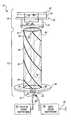
- FIG. 1is an illustration of a side view of a first embodiment of an antenna array in accordance with the invention.
- FIG. 2is an illustration of a top view of the first embodiment.
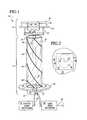
- FIG. 3is an illustration of a side view of a second embodiment of an antenna array in accordance with the invention.
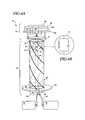
- FIG. 4Ais an illustration of a side view of a third embodiment of an antenna array in accordance with the invention.
- FIG. 4Bis an illustration of a trap circuit in accordance with the invention.
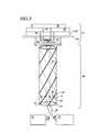
- FIG. 5is an illustration of a fourth embodiment of an antenna array in accordance with the invention.
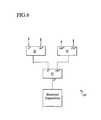
- FIG. 6is a block diagram of a quadrifilar helix feed network in accordance with the invention.
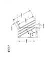
- FIG. 7is a schematic diagram of radiating elements employed in creating a quadrifilar helix antenna in accordance with the invention.
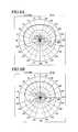
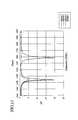
- FIGS. 8A and 8Bare charts reflecting measured elevation patterns in the L 1 and L 2 bands of a dual band quadrifilar helix antenna employed in a working null steering array model constructed in accordance with the invention.
- FIG. 9is a plot of reflection coefficients at the input feed points to each of the four arms of the working model.
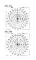
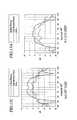
- FIGS. 10A and 10Bare charts reflecting measured elevation patterns in the L 1 and L 2 bands of a stacked microstrip patch antenna employed in a working null steering array model constructed in accordance with the invention.
- FIG. 11is a plot of reflection coefficients at the input feed points to each of the stacked microstrip patch elements of the working model.
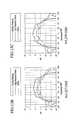
- FIGS. 12A-Care plots of synthesized radiation pattern plane cuts of the null steering array model using one complex weight across the L 1 band.
- FIGS. 13A-Care plots of synthesized radiation pattern plane cuts of the null steering array model using one complex weight across the L 2 band.
- the present inventionis directed toward microstrip patch/quadrifilar helix antenna arrays operable in either single frequency or multiple frequency bands. It should be noted that the description of the invention in terms of a GPS receiver is exemplary only, and in no way intended to be limiting. Artisans will readily appreciate that the rule of reciprocity allows the structures described below to be equally applicable to signal transmission, such as in communications systems.
- a means for supporting the patch 14 relative to the QHA 12is depicted to be a rigid bracket 16 connected to the bottom of the patch 14 .
- Any support meansmay be employed provided it does not interfere with the radiation patterns produced and the support means has sufficient rigidity to maintain a constant separation distance between the QHA 12 and patch 14 .
- the QHA 12is excited by signals in phase quadrature, i.e., four equi-amplitude signals whose phases have been shifted relative to an input signal 18 by 0°, 90°, 180° and 270°.
- the phase shifting and power-splitting of the input signal 18is accomplished by a QHA feed network 20 .
- Four signals 22are output from the QHA feed network 20 and fed to feeding locations 24 of the QHA 12 .
- the antenna arrayreceives circularly polarized signals from any direction in space with the same phasing network.
- Various configurations for feeding a patch antenna in order to produce circularly polarized radiation patternsare known.
- the auxiliary patch antenna 14is comprised of a patch element 32 stacked upon a dielectric substrate layer 34 and a ground plate 36 .
- the microstrip patch element 32preferably has a symmetric (e.g., square or round) shape and is dimensioned to be resonant in the desired frequency band.
- the bandwidths of patch antennasusually are narrower than for the QHA. Additionally, patches' polarization ratio near (or below) the horizon is not as desirable as QHA's. However, its smaller size is an obvious benefit.
- the assignee of the present applicationhas developed microstrip patch antennas for GPS receivers using high dielectric materials ( ⁇ >10) to reduce the area of the patch (See Rao, B.
- a patch feed network 26adaptively or predictively provides appropriately amplitude and phase weighted output signals 28 to patch feed pins 30 in such a manner as to generate an output radiation pattern that, when combined with the radiation output pattern of QHA 12 , results in a circularly polarized pattern minimum at a desired elevation angle.
- patch feed network 26provides, through use of a 90° hybrid (not shown), two patch feed signals 28 with a 90° phase offset.
- Patch element 32has two feed pins 30 for receiving the two patch feed signals 28 .
- the feed pins 30extend down through holes 38 in the dielectric substrate layer 34 and ground plate 36 .
- the longitudinal axes of these holesare aligned with the axis of the QHA 12 .
- circularly polarized radiation in a narrower bandwidthcould alternatively be provided by a single probe (one per patch), eliminating the need for the 90° feed hybrid.
- the patch feed signals 28may be transported on coaxial feed cables 40 disposed within a metal tube 42 extending along the central axis of QHA 12 with negligible impact on the array's performance.
- tube 42also serves as part of the support means for the patch antenna 14 , providing structural support for bracket 16 .
- each radiating elementhas a diametrically opposed radiating element that is driven out of phase, axially directed electric fields induced by the currents generated in the opposed radiating elements tend to cancel along the axis of QHA 12 . Consequently, the coupling to conducting tube 42 is minimized.
- Simulations and experiments conducted by the applicantshave demonstrated negligible impact of a tube with an approximate diameter of 0.36′′. More complex weighting and/or phase-shifting schemes, or structures employing alternative electrical connections for producing circular polarization which tracks the primary QHA 12 may be employed.
- FIG. 1illustrates a bottom-fed quadrifilar helix antenna 12 in accordance with an embodiment of the present invention.
- Each of four radiating elements 46 of the QHA 12is comprised of an electrically small conductor, such as a wire or flat ribbon, helically arranged such that they each traverse one helical turn, thereby defining a cylinder.
- a small ground plane 48is arranged perpendicularly to the cylinder defined by the radiating elements 46 .
- the ground plane 48is preferably circularly dimensioned and has a diameter greater than one third of the free space wavelength of the signals being received and/or transmitted.
- the helical arrangement of the radiating elements 46preferably has a left-hand twist in order to transmit and/or receive right hand circularly polarized signals and compensate for changes in the sense of polarization caused by reflections of circularly polarized electromagnetic signals from planar conductors.
- the radiating elements 46are comprised of strips of electrically conductive material printed on a dielectric support.
- the microstrip substrateis rolled or formed into a symmetric, preferably cylindrical shape, so that the radiating elements are wound about a central axis.
- the diameter of the cylindrical shapeis judiciously selected according to the desired impedance and bandwidth of the antenna. This cylindrical shape for the embodiments discussed below is not required to have a circular cross section.
- cross sectionrepresents an evenly distributed symmetrical shape, such as a rounded square, hexagon, octagon, and so forth, it is functional within the teachings of the present invention.
- pitch alteration effectscan be found in C. C. Kilgus, “Shaped Conical Radiation Pattern Performance of the Backfire Quadrifilar Helix”, IEEE Trans. AP , May 1975, p392-7, the contents of which are hereby incorporated by reference.
- each radiating element 46is selected for resonant operation in the desired frequency band in which the array 10 is intended to operate. Resonant operation typically requires a radiating element length which is approximately an odd integer multiple of a quarter wavelength .
- the radiating elements 46have sufficient rigidity such that they are self-supporting.
- the radiating elements 46may be supported by a cylindrical support structure 50 .
- a Styrofoam cylinderprovides structural support to the radiating elements.
- Foamtypically has a dielectric constant of less than 1.1. Higher dielectric constant material will allow the antenna to be made smaller, but also will reduce bandwidth (and radiation resistance).
- Each of the radiating elements 46is electrically open at one end 52 and has one of the conductive feed locations 24 at the other end.
- QHA feed network 20provides the 0°, 90°, 180° and 270° phase-shifted signals 22 needed to supply feed locations 24 , through holes in ground plane 48 , in order to produce circularly polarized radiation. Illustrated in FIG. 6 is a QHA feed network 20 comprised of a 180° hybrid 54 and two 90° hybrids 56 . The output of the 180° hybrid 54 is fed into the two 90° hybrids 56 .
- These hybrids deviceshave proven useful in implementing the teachings of the invention. However, those skilled in the art will appreciate that other known signal transfer structures besides those illustrated herein can be used.
- the QHA feed meanssimply requires production of four signals for the radiating elements 46 with substantially equal power and appropriate phase relationships. The choice of a specific feed network structure depends on design factors known by those skilled in the art, such as manufacturability, reliability, cost, and so forth.
- a purpose of the ground plane 48is to direct the radiation pattern of the QHA 12 in the forward axial direction.
- QHA'sare inherently backfire antennas, therefore the ground plane 48 is a necessary reflector in certain embodiments.
- the need for a ground planeis eliminated by feeding the radiating elements 46 at the feed locations 24 , which are, in these embodiments, located at the “top” of the antenna, and by changing the rotational twist of the radiating elements to a right-hand twist.
- the reference to “top” heremeans the end of the radiating elements 46 closer to the patch 14 .
- the QHA feed signals 22may be transported via coaxial cables 58 from the feed network 20 to the feed locations 24 through tube 42 , which also transports patch feed signals 28 .
- the present inventionprovides an antenna array capable of steering circularly polarized radiation pattern minima to selected elevation angles in separate frequency bands (e.g., L 1 and L 2 ).
- the desired patternsare generated by a compact antenna array 59 comprised of a primary dual-band QHA 60 and coaxially aligned and vertically displaced auxiliary stacked patch antenna 61 .
- the primary antennais a trap-loaded QHA 60 such as described in the applicant's co-pending U.S. application Ser. No. 10/174,330 entitled “Dual-Band Quadrifilar Helix Antenna”, filed Jun. 18, 2002, the contents of which are a incorporated by reference herein in their entirety.
- the trap-loaded QHAIn both of its operating frequency bands, the trap-loaded QHA has a relatively small gain variation. It also has low axial ratio (low cross-polarization) over the hemisphere, which can suppress multipath reflections.
- dual-band helical configurationsmay also be used as primary antennas with some degradation of overall array performance, however use of the trap-loaded QHA 60 minimizes the number of duplexers required in the nulling circuit, with a single output port from the trap-loaded QHA (after a hybrid combining network) for both frequency bands and two output ports from the auxiliary stacked patch antenna (one for each frequency) 61 .
- Each of the four radiating elements 62 of the trap-loaded QHA 60is comprised of an electrically small conductor, such as a wire or flat ribbon, having an upper portion 64 and a lower portion 66 and a trap circuit 72 disposed in a gap 68 between the upper portion and the lower portion.
- the trap-loaded QHAshares a number of characteristics with the QHA described above.
- Each of its radiating elements 62are helically arranged with a left twist for obtaining right hand circular polarization, and may be similarly rolled or formed from a microstrip substrate (as shown in FIG. 7) into a symmetric shape about a central axis.
- the radiating elements 62may also similarly be self-supporting or supported by a support structure 68 conforming to the symmetric shape.
- each radiating element 62(including the trap 72 ) is selected for resonant operation in a first frequency band, the first frequency band being the lower of the two frequency bands at which the antenna array 59 is intended to operate. Resonant operation typically requires a radiating element length which is approximately an odd integer multiple of a quarter wavelength.
- Each of the upper portions 64 of the radiating elements 62is electrically open at one end 70 and electrically connected to a trap circuit 72 at the other end 74 .
- Each of the lower portions 66is electrically connected to the trap circuit 72 at one end 76 and is electrically connected to a QHA feed network 78 through conductive feed points 80 located at the other end.
- the radiating elements 62are designed such that the trap circuits 72 are disposed between each upper portion 64 and lower portion 66 at a point such that all of the upper portions 64 are of equal lengths and all of the lower portions 66 are of equal lengths. That is, the trap circuits 72 are equidistant from the respective open ends 70 of the radiating elements 62 in which they are disposed. This position is selected to be the point at which the resulting length of the lower portions 64 of the radiating elements 62 corresponds to resonance at the second (higher) frequency.
- the trap circuits 72are passive circuits that operate as switches. As shown in FIG. 4B, they are each comprised of a parallel LC circuit (lumped components) that has infinite impedance (i.e., it forms an open circuit) at its resonant frequency. At the lower frequency, the trap circuits have low reactive impedance that can be compensated by a slight change in the length of the upper portions 64 . Thus, at the resonant frequency of the trap circuits, which coincides with the center frequency of the higher operational frequency band of the antenna, only the lower portions 66 of the trap-loaded QHA 60 effectively radiate energy.
- the dual-band QHA 60requires a feed network 78 to provide the 0°, 90°, 180° and 270° feed signals 84 needed to drive radiating elements 62 .
- a feed networksuch as illustrated in FIG. 6 and electrical connection scheme as described above is suitable and was employed in the working model described below.
- directing the radiation pattern from this “bottom-fed” trap-loaded QHA 60 in the forward axial directionrequires placement of a small ground plane 82 perpendicular to the axis of the cylinder defined by the radiating elements 62 and proximate to the feed points 80 to redirect the inherently backfire radiation.
- the ground plane 82may have any shape, but is preferably circular and has a diameter equal to or greater than one third of the free space wavelength of the signals being received and/or transmitted.
- FIG. 5illustrates an embodiment of the antenna array 59 employing a “top-fed” trap-loaded QHA 60 which requires no ground plane but a right-hand twist for its radiating elements 62 .
- a signal transport scheme similar to that described aboveis preferably employed, wherein trap-loaded feed signals 84 are transported on coaxial feed cables 86 disposed within a tube 88 extending along the central axis of the trap-loaded QHA 60 with negligible impact on the array's performance.
- the tube 88may additionally provide mechanical support to the stacked patch antenna 61 and preferably also transports stacked patch feed signals 90 from the patch feed network 92 to one or more feed pins 94 of each auxiliary patch element 96 , 98 .
- the auxiliary stacked patch antenna 61is comprised of two symmetrically shaped microstrip patches 96 , 98 that are stacked one above the other with a high dielectric substrate layer 100 and a small ground plane 102 beneath them.
- This arrangementcreates a double tuned circuit, with the upper auxiliary patch 96 resonant at the higher frequency (e.g., L 1 ), and the lower auxiliary patch 98 that has a larger surface area resonant at the lower frequency (e.g., L 2 ).
- the small ground plane 102( ⁇ 2′′ per side in this L band model) makes it both dimensionally compact and also improves the polarization ratio of the patch pattern at or near the horizon.
- optimal circular polarization excitation of the stacked patch 61occurs through direct connections to two pairs of feed pins 94 , one pair for each auxiliary patch element 96 , 98 .
- alternative excitation schemesare known and considered to be within the scope of the present invention.
- excitation schemes employing fewer direct connectionsmay employed, or even configurations wherein excitation is provided through electromagnetic coupling (such as described by D. M Pozar el al., “A Dual-Band Circularly Polarized Aperture-Coupled Stacked Microstrip Antenna for Global Position Satellite”, IEEE Trans. Antennas and Propagation , Vol.
- each pair of feed pins 96 , 98is fed with 90° phase separated patch feed signals 90 .
- These signalscan be obtained from a patch feed network 92 comprised of a 90° hybrid.
- the location of each pair of feed pins 94is chosen to minimize the reflection loss for each resonant frequency.
- the applicantshave successfully designed and constructed a dual frequency band null steering array for use in satellite navigation and/or communications systems, and especially with an adaptive nulling processor for interference rejection.
- the arraywas designed to provide rhcp coverage over a hemisphere at two frequencies, 1227 MHz and 1575 MHz (the L 2 and L 1 GPS bands) and to selectively steer pattern minima in both frequency bands along the horizon in order to suppress interfering signals.
- the modelis configured with a small ground plane (2′′ in diameter) at the base of a trap-loaded QHA.
- the dimensions, in inches, of four radiating elements that were formed into the model trap-loaded QHAare reflected in FIG. 7 .
- the radiating elementswere formed from narrow copper strips positioned upon a thin, flexible mylar sheet that was then rolled into a cylinder approximately 1 inch in diameter.
- a Styrofoam corewas employed to maintain the cylindrical shape and provide support for the radiating elements.
- the resonant input impedance at the two specified frequencieswas approximately 50 ohms.
- LCWhile the product, LC, must be determined by the resonant frequency of the trap circuit, the choice of a particular combination of L and C affects the required length of the upper portions of the radiating elements. Also, if the inductance has significant ohmic loss, it will reduce the radiation efficiency at the lower frequency band.
- the four radiating elementswere attached at their feed points to the center conductors of four coaxial connectors through a ground plate whose diameter of approximately 3 inches was selected to reflect most of the energy radiated from the antenna to the upper hemisphere while still maintaining coverage for angles just below the horizon (i.e., a cardioid pattern).
- the nulling capability and the associated patterns of the patch/helix antenna arraywas evaluated by measurements and pattern synthesis simulation.
- the antenna patternswere measured using a spherical near field scanner.
- FIGS. 8A and 8Bdepict elevation plane patterns for the trap-loaded QHA measured at the center frequencies of the L 1 and L 2 frequency bands.
- the solid-line curvesrepresent the right hand circularly polarized patterns and the dashed-line curves represent the left hand circularly polarized patterns, respectively.
- the antennaachieves small gain variation ( ⁇ 4 dB over the upper hemisphere and ⁇ 2 dB to 80 degrees from the zenith).
- the input match for the trap-loaded QHAis illustrated in FIG. 9 by an overlay of the reflection coeficients at the input (feed points) to each of the four arms (radiating elements) of the helix.
- the QHA feed networkwas designed and created from commercial off the shelf components, a 180° hybrid and two 90° hybrids, that are compact and wideband.
- FIGS. 10A and 10Bdepict elevation plane patterns for the stacked patch antenna measured at the center frequencies of the L 1 and L 2 bands.
- Using a separate pair of probes (feed pins) to excite each patch with 90° phase separationoptimized the polarization ratio for right-hand circular polarization over most of the field of view. The location of each pair of probes was chosen to minimize the reflection loss for each frequency as shown in FIG. 11 .
- the amplitude and phase patterns of the antennaswere each measured at the center and edge frequencies in both the L 1 and L 2 frequency bands.
- the two measured right-hand circular polarization patternswere added using a computer synthesis to create a composite pattern with the appropriate amplitude and phase weight.
- the weightwas chosen for the center frequency and the same weight applied to the patterns band edge frequencies to demonstrate the frequency sensitivity of the weights.
- the resulting elevation plane cutsare shown in FIGS. 12A-C for L 1 and FIGS. 13A-C for L 2 . Note that creating the ring null near the horizon with two antenna elements increases the gain over most of the remainder of the upper hemisphere.
- a compact protective radomemay be used.
- the radomecould be formed from a dense foam or a more rigid, but thin, composite material. The latter would require retuning the four radiating elements of the helix (modifying their length) to compensate for the effect of the dielectric material in the radome.
- the trap circuitscould be created from printed circuit components (L and C) rather than the discrete components that were used in the model described above.
- the feed networksare depicted as being disposed below the helix. Alternatively, the feed networks could be placed in the gap between the QHA and the ground plane of the patch (or stacked patch) antenna. It is intended that the specification and examples be considered as exemplary only, with the true scope and spirit of the invention being indicated by the following claims.
Landscapes
- Variable-Direction Aerials And Aerial Arrays (AREA)
Abstract
Description
The U.S. Government has certain rights in this patent as provided for by the terms of contract No. 03016132 A8, NAVWAR FY01 awarded by the Department of Defense.
The invention relates generally to antennas for use in communication and navigation systems. In particular, the invention relates to a single or dual band antenna array for receiving and/or transmitting circularly polarized signals in the presence of hostile or unintentional interference.
Many contemporary communications and navigation products have been developed that rely on earth-orbiting satellites to provide necessary communications and navigation signals. Examples of such products include satellite navigation systems, satellite tracking and locator systems (e.g., GPS), and communications systems (e.g., NAVSTAR) that rely on satellites to relay the communications signals from one station to another. In order for these products to be operationally useful as hand-held equipment, the antennas they employ should be small (comparable or smaller in size than the receiver itself).
Several types of antennas are now used with hand-held GPS receivers. All are relatively compact and can receive circularly polarized signals from any direction above the ground (e.g., hemispherical coverage, although gain along the ground or horizon can be reduced). The requirement for compact size has several performance benefits in addition to its obvious portability. It enables the radiation pattern of an antenna to have slowly varying gain and low frequency dispersion over most of the field of view. The latter is important to provide the desired location accuracy. But any communications or navigation system is susceptible to degradation due to interfering conditions. Carrier signals are vulnerable to interruption by natural phenomena, interference from other signals or countermeasures. Countermeasures may take the form of a variety of jamming schemes whose sole purpose is to disrupt the operation of a receiver.
Multipath is a significant problem in both navigational and communications systems. It degrades navigational accuracy in GPS systems and can be a source of interference in communications systems. Multipath can be caused by “structural” reflections from specular reflecting surfaces of numerous scattering sources common to an urban environment such as buildings, large vehicles, aircraft or ships. Alternatively, multipath can be caused by ground reflections at low grazing angles off the moist ground, rooftops, sea surface or a large body of water close to the antenna. Since GPS satellites transmit right-handed circularly polarized (RHCP) signals, and the polarization of a multipath signal after reflection is normally reversed, the rejection of the cross-polarized (left-handed circularly polarized, LHCP) signals is important in avoiding multipath problems.
Various types of antennas have been proposed for decreasing the effects of interference. In addition to their large size, most have large numbers of radiating elements that make them unsuitable for use in hand-held devices such as GPS receivers. Additionally, most do not allow operation in more than one frequency band. For the next generation of GPS hand-held receivers being developed for the military, it will be necessary to receive circularly polarized signals in two frequency bands, (L1 and L2). In addition, it is desired to be able to suppress active interference signals (e.g., jammers) by predictively or adaptively placing a radiation pattern minimum in the direction of that interference. This requires one or more auxiliary antennas whose output would be combined with the output of the primary antenna(s) with an adaptive weight to appropriately shape the pattern.
Thus, a need exists for a simple predictive or adaptive antenna array compact enough to be suitable for use in a hand-held device, yet which is capable of receiving and/or transmitting circularly polarized signals in more than one (preferably satellite) frequency band while providing a relatively high gain quasi-hemispherical radiation pattern over those bands.
The present invention provides an antenna array that is operationally useful in hand-held communications and navigation (e.g., GPS) transceivers and receivers. Some embodiments of the antenna array are capable of receiving and/or transmitting circularly polarized signals within separate frequency bands. In addition, in order to suppress incident signals that would potentially interfere with the desire signal, a pattern minimum (predictive or adaptive) can be steered in the direction of an interfering signal. An appropriate amplitude and phase weight is applied to the output of an auxiliary antenna such that, when combined with the output of a primary antenna, generates the pattern minimum. The pattern minimum created by this two-element antenna array will have a conical shape with the axis of the cone along a line separating the primary and auxiliary antenna elements. Because most interfering signals are anticipated to arrive from a direction close to the horizon, a vertical displacement between the primary and auxiliary elements is preferred, though not required, in order to steer the pattern minimum along the horizon while providing maximum pattern gain in the upper hemisphere.
Antennas that are electrically small, passive and have low ohmic loss will have a relatively narrow bandwidth and high Q. Essentially such antennas are resonant circuits, with the non-ohmic loss representing radiation. By modifying the design of such antennas to be the equivalent of a double-tuned resonant circuit, they may operated efficiently in two distinct frequency bands (e.g., L1 and L2). This is a technique used in certain embodiments of the present invention, wherein the technique is applied to both a quadrifilar helix antenna (QHA) and a microstrip patch antenna (patch).
In a first embodiment, the present invention provides a spatial null steering antenna array comprised of a primary QHA resonating circularly polarized radiation in a desired frequency band and means for feeding the QHA in phase quadrature (i.e., feed signals having relative phase differences of 0°, 90°, 180° and 270° from an input signal) such as described below. Coaxially aligned and vertically displaced from the QHA is an auxiliary patch antenna resonant in the same frequency band. The patch is stacked atop a dielectric substrate layer and a ground plate. The positions of the patch, substrate layer and patch ground plate are fixed relative to the QHA. A means for applying an appropriate amplitude and phase weight to feed signals feeding the patch results in a combined circularly polarized radiation pattern minimum at selected elevation angles. The desired frequency band is preferably a satellite frequency band, such as either of the L1 or L2 bands.
Several QHA designs are known to artisans. In one bottom-fed embodiment, the QHA is comprised of four radiating elements arranged helically with a left-hand twist to define a cylinder of constant radius, each radiating element having an electrically open end below the patch ground plate and another end having an electrically conductive feed location, and a QHA ground plane coaxially positioned below the four radiating elements. In some embodiments, the radiating elements have sufficient rigidity to be self-support, while in others they are structurally supported. In other top-fed embodiments, the need for a QHA ground plane is eliminated by taking advantage of the inherent backfire nature of QHA's. In these top-fed embodiments, the radiating elements have a right-hand twist and the electrically-open and feed-location ends are inverted. The radiating elements may be comprised of strips of electrically conductive material printed on a dielectric support. The radiating elements each has a length preferably less than or equal to the wavelength in free space of the signals being fed, and each preferably completes one helical turn about the (imaginary) defined cylinder.
In certain preferred embodiments, the auxiliary patch feed signals are transported from the patch feed means to the patch via a conduit located coaxially within and extending above the QHA. The conduit also preferably transports the QHA feed signals in certain top-fed embodiments. In some embodiments, the conduit also serves as portion of a support mechanism for fixing the position of the patch, substrate layer and patch ground plate relative to the QHA. The patch may be fed predictively, as mentioned above, with appropriately amplitude and phase weighted feed signals to achieve a pattern minimum at the horizon. Alternatively, the patch may be fed by an adaptive weighting feed network in order to steer the pattern minimum to other elevations from where interfering signals may be arriving.
In another embodiment, the present invention provides a dual-band spatial null steering antenna array comprised of a primary dual-band QHA and a coaxially aligned and vertically displaced auxiliary stacked patch antenna, each of which is resonant in a first frequency band and a second frequency band, means for feeding the dual-band QHA to produce circularly polarized radiation in the first frequency band and the second frequency band, and means for feeding the stacked patch antenna to produced circularly polarized radiation such that, when combined with the output of the dual-band QHA, generates pattern minima in the first and second frequency bands at selected elevation angles. The first and second frequency bands are preferably, but not limited to, the L2 and L1 GPS bands, respectively.
An auxiliary stacked patch antenna as used herein comprises a patch ground plane coaxially aligned with and vertically displaced above the dual-band quadrifilar helix antenna, and a first auxiliary patch resonant in the first frequency band and a second auxiliary patch resonant in the second frequency band coaxially aligned and vertically stacked on a dielectric substrate layer on top of the patch ground plate. The first auxiliary patch and second auxiliary patch may be feed predictively or adaptively by the patch feed network in each of the two frequency bands. Appropriate feeding may occur simultaneously in both frequency bands, or alternating between the two frequency bands as desired.
As in the single frequency band embodiments of the present invention, a means for supporting the position of the auxiliary stacked patch antenna relative to the dual-band QHA is preferably employed, as well as an optional means for supporting the structure of the dual-band QHA. The auxiliary stacked patch support means may similarly comprise a conduit mechanism through which patch feed signals are transported from the patch feed network.
Several dual-band QHA's are known and may be employed, but in preferred embodiments the present invention employs trap-loaded QHA's as described below. Generally speaking, trap-loaded QHA's employ radiating elements in which are inserted parallel LC circuits whose impedance in the second frequency band is significantly higher than in the first frequency band, thus effecting the double tuning mentioned above. The details of the trap-loaded QHA and the combination of its output radiation pattern with that of the auxiliary stacked patch antenna will be described in detail below.
FIG. 1 is an illustration of a side view of a first embodiment of an antenna array in accordance with the invention.
FIG. 2 is an illustration of a top view of the first embodiment.
FIG. 3 is an illustration of a side view of a second embodiment of an antenna array in accordance with the invention.
FIG. 4A is an illustration of a side view of a third embodiment of an antenna array in accordance with the invention.
FIG. 4B is an illustration of a trap circuit in accordance with the invention.
FIG. 5 is an illustration of a fourth embodiment of an antenna array in accordance with the invention.
FIG. 6 is a block diagram of a quadrifilar helix feed network in accordance with the invention.
FIG. 7 is a schematic diagram of radiating elements employed in creating a quadrifilar helix antenna in accordance with the invention.
FIGS. 8A and 8B are charts reflecting measured elevation patterns in the L1 and L2 bands of a dual band quadrifilar helix antenna employed in a working null steering array model constructed in accordance with the invention.
FIG. 9 is a plot of reflection coefficients at the input feed points to each of the four arms of the working model.
FIGS. 10A and 10B are charts reflecting measured elevation patterns in the L1 and L2 bands of a stacked microstrip patch antenna employed in a working null steering array model constructed in accordance with the invention.
FIG. 11 is a plot of reflection coefficients at the input feed points to each of the stacked microstrip patch elements of the working model.
FIGS. 12A-C are plots of synthesized radiation pattern plane cuts of the null steering array model using one complex weight across the L1 band.
FIGS. 13A-C are plots of synthesized radiation pattern plane cuts of the null steering array model using one complex weight across the L2 band.
Certain embodiments of the invention will now be described with reference to the accompanying figures. The present invention is directed toward microstrip patch/quadrifilar helix antenna arrays operable in either single frequency or multiple frequency bands. It should be noted that the description of the invention in terms of a GPS receiver is exemplary only, and in no way intended to be limiting. Artisans will readily appreciate that the rule of reciprocity allows the structures described below to be equally applicable to signal transmission, such as in communications systems.
In a first embodiment depicted in FIGS. 1 and 2, the present invention comprises anarray 10, which itself is comprised of aQHA 12 and amicrostrip patch antenna 14 that is coaxially aligned with and vertically displaced above theQHA 12. TheQHA 12 and thepatch antenna 14 are both resonant in the same frequency band, which is preferably a satellite frequency band (e.g., L1 or L2), although other bands are possible. Through appropriate predictive or adaptive excitation, thepatch antenna 14 operates as an auxiliary element to theprimary element QHA 12, allowing the steering of a circularly polarized radiation pattern minimum to a desired elevation from which interfering signals are being received. A means for supporting thepatch 14 relative to theQHA 12 is depicted to be arigid bracket 16 connected to the bottom of thepatch 14. Any support means may be employed provided it does not interfere with the radiation patterns produced and the support means has sufficient rigidity to maintain a constant separation distance between theQHA 12 andpatch 14.
In order to produce circularly polarized radiation, theQHA 12 is excited by signals in phase quadrature, i.e., four equi-amplitude signals whose phases have been shifted relative to aninput signal 18 by 0°, 90°, 180° and 270°. The phase shifting and power-splitting of theinput signal 18 is accomplished by aQHA feed network 20. Four signals22 are output from theQHA feed network 20 and fed to feedinglocations 24 of theQHA 12. By reciprocity, the antenna array receives circularly polarized signals from any direction in space with the same phasing network. Various configurations for feeding a patch antenna in order to produce circularly polarized radiation patterns are known.
Theauxiliary patch antenna 14 is comprised of apatch element 32 stacked upon adielectric substrate layer 34 and aground plate 36. Themicrostrip patch element 32 preferably has a symmetric (e.g., square or round) shape and is dimensioned to be resonant in the desired frequency band. The bandwidths of patch antennas usually are narrower than for the QHA. Additionally, patches' polarization ratio near (or below) the horizon is not as desirable as QHA's. However, its smaller size is an obvious benefit. The assignee of the present application has developed microstrip patch antennas for GPS receivers using high dielectric materials (ε>10) to reduce the area of the patch (See Rao, B. Rama et al., “Characterizing the Effects of Mutual Coupling on the Performance of a Miniaturized GPS Adaptive Array”, GPS-ION Symposium, September 2000, Salt Lake City, the contents of which are hereby incorporated by reference in their entirety.) If the axial separation between the two antennas is almost λ/2, the pattern minimum near the horizon will be relatively narrow. Also, when a minimum for the combined pattern is created near the horizon, this separation plus the phase weight will cause the two patterns to add coherently above the horizon increasing the overall gain of the adapted antenna pattern.
Apatch feed network 26 adaptively or predictively provides appropriately amplitude and phase weighted output signals28 to patch feed pins30 in such a manner as to generate an output radiation pattern that, when combined with the radiation output pattern ofQHA 12, results in a circularly polarized pattern minimum at a desired elevation angle. In a preferred embodiment (as shown in FIGS.1 and2), wherein a circularly polarized pattern minimum is desired at the horizon,patch feed network 26 provides, through use of a 90° hybrid (not shown), two patch feed signals28 with a 90° phase offset.Patch element 32 has twofeed pins 30 for receiving the two patch feed signals28. In a preferred embodiment, the feed pins30 extend down throughholes 38 in thedielectric substrate layer 34 andground plate 36. The longitudinal axes of these holes are aligned with the axis of theQHA 12. Note that circularly polarized radiation in a narrower bandwidth could alternatively be provided by a single probe (one per patch), eliminating the need for the 90° feed hybrid. The patch feed signals28 may be transported oncoaxial feed cables 40 disposed within ametal tube 42 extending along the central axis ofQHA 12 with negligible impact on the array's performance. In certain embodiments,tube 42 also serves as part of the support means for thepatch antenna 14, providing structural support forbracket 16. Since each radiating element has a diametrically opposed radiating element that is driven out of phase, axially directed electric fields induced by the currents generated in the opposed radiating elements tend to cancel along the axis ofQHA 12. Consequently, the coupling to conductingtube 42 is minimized. Simulations and experiments conducted by the applicants have demonstrated negligible impact of a tube with an approximate diameter of 0.36″. More complex weighting and/or phase-shifting schemes, or structures employing alternative electrical connections for producing circular polarization which tracks theprimary QHA 12 may be employed.
FIG. 1 illustrates a bottom-fedquadrifilar helix antenna 12 in accordance with an embodiment of the present invention. Each of four radiatingelements 46 of theQHA 12 is comprised of an electrically small conductor, such as a wire or flat ribbon, helically arranged such that they each traverse one helical turn, thereby defining a cylinder. Asmall ground plane 48 is arranged perpendicularly to the cylinder defined by the radiatingelements 46. Theground plane 48 is preferably circularly dimensioned and has a diameter greater than one third of the free space wavelength of the signals being received and/or transmitted.
The helical arrangement of the radiatingelements 46 preferably has a left-hand twist in order to transmit and/or receive right hand circularly polarized signals and compensate for changes in the sense of polarization caused by reflections of circularly polarized electromagnetic signals from planar conductors. According to certain preferred embodiments, the radiatingelements 46 are comprised of strips of electrically conductive material printed on a dielectric support. The microstrip substrate is rolled or formed into a symmetric, preferably cylindrical shape, so that the radiating elements are wound about a central axis. The diameter of the cylindrical shape is judiciously selected according to the desired impedance and bandwidth of the antenna. This cylindrical shape for the embodiments discussed below is not required to have a circular cross section. As long as the cross section represents an evenly distributed symmetrical shape, such as a rounded square, hexagon, octagon, and so forth, it is functional within the teachings of the present invention. Additionally, those skilled in the art will readily appreciate that some changes may be required to alter the radiation pattern of the antenna commensurate with the expected use of the antenna and operational requirements of a particular communication or navigation system. For example, a discussion of pitch alteration effects can be found in C. C. Kilgus, “Shaped Conical Radiation Pattern Performance of the Backfire Quadrifilar Helix”,IEEE Trans. AP, May 1975, p392-7, the contents of which are hereby incorporated by reference. The overall length of each radiatingelement 46 is selected for resonant operation in the desired frequency band in which thearray 10 is intended to operate. Resonant operation typically requires a radiating element length which is approximately an odd integer multiple of a quarter wavelength . In certain embodiments, the radiatingelements 46 have sufficient rigidity such that they are self-supporting. In other embodiments, the radiatingelements 46 may be supported by acylindrical support structure 50. For example, in an experimental model described below, a Styrofoam cylinder provides structural support to the radiating elements. Foam typically has a dielectric constant of less than 1.1. Higher dielectric constant material will allow the antenna to be made smaller, but also will reduce bandwidth (and radiation resistance).
Each of the radiatingelements 46 is electrically open at oneend 52 and has one of theconductive feed locations 24 at the other end.QHA feed network 20 provides the 0°, 90°, 180° and 270° phase-shiftedsignals 22 needed to supplyfeed locations 24, through holes inground plane 48, in order to produce circularly polarized radiation. Illustrated in FIG. 6 is aQHA feed network 20 comprised of a 180°hybrid 54 and two 90°hybrids 56. The output of the 180°hybrid 54 is fed into the two 90°hybrids 56. These hybrids devices have proven useful in implementing the teachings of the invention. However, those skilled in the art will appreciate that other known signal transfer structures besides those illustrated herein can be used. The QHA feed means simply requires production of four signals for the radiatingelements 46 with substantially equal power and appropriate phase relationships. The choice of a specific feed network structure depends on design factors known by those skilled in the art, such as manufacturability, reliability, cost, and so forth.
A purpose of theground plane 48 is to direct the radiation pattern of theQHA 12 in the forward axial direction. QHA's are inherently backfire antennas, therefore theground plane 48 is a necessary reflector in certain embodiments.
In certain alternative embodiments, one of which is depicted in FIG. 3, the need for a ground plane is eliminated by feeding the radiatingelements 46 at thefeed locations 24, which are, in these embodiments, located at the “top” of the antenna, and by changing the rotational twist of the radiating elements to a right-hand twist. The reference to “top” here means the end of the radiatingelements 46 closer to thepatch 14. In these embodiments, the QHA feed signals22 may be transported viacoaxial cables 58 from thefeed network 20 to thefeed locations 24 throughtube 42, which also transports patch feed signals28.
In another embodiment, the present invention provides an antenna array capable of steering circularly polarized radiation pattern minima to selected elevation angles in separate frequency bands (e.g., L1 and L2). The desired patterns are generated by acompact antenna array 59 comprised of a primary dual-band QHA 60 and coaxially aligned and vertically displaced auxiliary stackedpatch antenna 61.
In a preferred embodiment illustrated in FIG. 4 the primary antenna is a trap-loadedQHA 60 such as described in the applicant's co-pending U.S. application Ser. No. 10/174,330 entitled “Dual-Band Quadrifilar Helix Antenna”, filed Jun. 18, 2002, the contents of which are a incorporated by reference herein in their entirety. In both of its operating frequency bands, the trap-loaded QHA has a relatively small gain variation. It also has low axial ratio (low cross-polarization) over the hemisphere, which can suppress multipath reflections. Other dual-band helical configurations (e.g., concentric and interleaved helices)may also be used as primary antennas with some degradation of overall array performance, however use of the trap-loadedQHA 60 minimizes the number of duplexers required in the nulling circuit, with a single output port from the trap-loaded QHA (after a hybrid combining network) for both frequency bands and two output ports from the auxiliary stacked patch antenna (one for each frequency)61.
Each of the four radiatingelements 62 of the trap-loadedQHA 60 is comprised of an electrically small conductor, such as a wire or flat ribbon, having anupper portion 64 and alower portion 66 and atrap circuit 72 disposed in agap 68 between the upper portion and the lower portion. The trap-loaded QHA shares a number of characteristics with the QHA described above. Each of its radiatingelements 62 are helically arranged with a left twist for obtaining right hand circular polarization, and may be similarly rolled or formed from a microstrip substrate (as shown in FIG. 7) into a symmetric shape about a central axis. The radiatingelements 62 may also similarly be self-supporting or supported by asupport structure 68 conforming to the symmetric shape. The dimensioning of this preferably cylindrical shape will be affected by the pattern shaping and bandwidth design choices described above. The overall length of each radiating element62 (including the trap72) is selected for resonant operation in a first frequency band, the first frequency band being the lower of the two frequency bands at which theantenna array 59 is intended to operate. Resonant operation typically requires a radiating element length which is approximately an odd integer multiple of a quarter wavelength. Each of theupper portions 64 of the radiatingelements 62 is electrically open at oneend 70 and electrically connected to atrap circuit 72 at theother end 74. Each of thelower portions 66 is electrically connected to thetrap circuit 72 at oneend 76 and is electrically connected to aQHA feed network 78 through conductive feed points80 located at the other end. An advantage of present invention is that both frequency bands may be fed through the feed points80. To provide resonant operation in the higher frequency band, the radiatingelements 62 are designed such that thetrap circuits 72 are disposed between eachupper portion 64 andlower portion 66 at a point such that all of theupper portions 64 are of equal lengths and all of thelower portions 66 are of equal lengths. That is, thetrap circuits 72 are equidistant from the respective open ends70 of the radiatingelements 62 in which they are disposed. This position is selected to be the point at which the resulting length of thelower portions 64 of the radiatingelements 62 corresponds to resonance at the second (higher) frequency.
Thetrap circuits 72 are passive circuits that operate as switches. As shown in FIG. 4B, they are each comprised of a parallel LC circuit (lumped components) that has infinite impedance (i.e., it forms an open circuit) at its resonant frequency. At the lower frequency, the trap circuits have low reactive impedance that can be compensated by a slight change in the length of theupper portions 64. Thus, at the resonant frequency of the trap circuits, which coincides with the center frequency of the higher operational frequency band of the antenna, only thelower portions 66 of the trap-loadedQHA 60 effectively radiate energy.
The dual-band QHA 60 requires afeed network 78 to provide the 0°, 90°, 180° and 270° feed signals84 needed to drive radiatingelements 62. A feed network such as illustrated in FIG.6 and electrical connection scheme as described above is suitable and was employed in the working model described below. As in the case of the single frequency QHA, directing the radiation pattern from this “bottom-fed” trap-loadedQHA 60 in the forward axial direction (toward the upper hemisphere) requires placement of asmall ground plane 82 perpendicular to the axis of the cylinder defined by the radiatingelements 62 and proximate to the feed points80 to redirect the inherently backfire radiation. Theground plane 82 may have any shape, but is preferably circular and has a diameter equal to or greater than one third of the free space wavelength of the signals being received and/or transmitted.
FIG. 5 illustrates an embodiment of theantenna array 59 employing a “top-fed” trap-loadedQHA 60 which requires no ground plane but a right-hand twist for its radiatingelements 62. A signal transport scheme similar to that described above is preferably employed, wherein trap-loaded feed signals84 are transported oncoaxial feed cables 86 disposed within atube 88 extending along the central axis of the trap-loadedQHA 60 with negligible impact on the array's performance. Thetube 88 may additionally provide mechanical support to the stackedpatch antenna 61 and preferably also transports stacked patch feed signals90 from thepatch feed network 92 to one or more feed pins94 of eachauxiliary patch element
The auxiliarystacked patch antenna 61 is comprised of two symmetrically shapedmicrostrip patches dielectric substrate layer 100 and asmall ground plane 102 beneath them. This arrangement creates a double tuned circuit, with the upperauxiliary patch 96 resonant at the higher frequency (e.g., L1), and the lowerauxiliary patch 98 that has a larger surface area resonant at the lower frequency (e.g., L2). A high dielectric constant (ε=12.8) material was used to form thesubstrate layer 100 of the working model described below, helping to reduce the antenna's overall size. The small ground plane102 (˜2″ per side in this L band model) makes it both dimensionally compact and also improves the polarization ratio of the patch pattern at or near the horizon.
In the embodiments illustrated in FIGS. 4 and 5, optimal circular polarization excitation of the stackedpatch 61 occurs through direct connections to two pairs of feed pins94, one pair for eachauxiliary patch element patch feed network 92 comprised of a 90° hybrid. The location of each pair of feed pins94 is chosen to minimize the reflection loss for each resonant frequency.
The applicants have successfully designed and constructed a dual frequency band null steering array for use in satellite navigation and/or communications systems, and especially with an adaptive nulling processor for interference rejection. The array was designed to provide rhcp coverage over a hemisphere at two frequencies, 1227 MHz and 1575 MHz (the L2 and L1 GPS bands) and to selectively steer pattern minima in both frequency bands along the horizon in order to suppress interfering signals. The model is configured with a small ground plane (2″ in diameter) at the base of a trap-loaded QHA. The auxiliary stacked patch antenna is comprised of two square microstrip patches stacked one above the other with a high dielectric substrate (εr=12.8) and small ground plane below them.
The dimensions, in inches, of four radiating elements that were formed into the model trap-loaded QHA are reflected in FIG.7. The radiating elements were formed from narrow copper strips positioned upon a thin, flexible mylar sheet that was then rolled into a cylinder approximately 1 inch in diameter. A Styrofoam core was employed to maintain the cylindrical shape and provide support for the radiating elements. For this design, the resonant input impedance at the two specified frequencies was approximately 50 ohms. The trap circuits' components, inductors (L=6.8 nh) and capacitors (C=1.5 pf), were soldered across the gap in each radiating element at approximately 0.6 inches from the open ends of the radiating elements. While the product, LC, must be determined by the resonant frequency of the trap circuit, the choice of a particular combination of L and C affects the required length of the upper portions of the radiating elements. Also, if the inductance has significant ohmic loss, it will reduce the radiation efficiency at the lower frequency band. The four radiating elements were attached at their feed points to the center conductors of four coaxial connectors through a ground plate whose diameter of approximately 3 inches was selected to reflect most of the energy radiated from the antenna to the upper hemisphere while still maintaining coverage for angles just below the horizon (i.e., a cardioid pattern).
The nulling capability and the associated patterns of the patch/helix antenna array was evaluated by measurements and pattern synthesis simulation. The antenna patterns were measured using a spherical near field scanner.
FIGS. 8A and 8B depict elevation plane patterns for the trap-loaded QHA measured at the center frequencies of the L1 and L2 frequency bands. The solid-line curves represent the right hand circularly polarized patterns and the dashed-line curves represent the left hand circularly polarized patterns, respectively. Note that the antenna achieves small gain variation (<4 dB over the upper hemisphere and <2 dB to 80 degrees from the zenith). The input match for the trap-loaded QHA is illustrated in FIG. 9 by an overlay of the reflection coeficients at the input (feed points) to each of the four arms (radiating elements) of the helix. The QHA feed network was designed and created from commercial off the shelf components, a 180° hybrid and two 90° hybrids, that are compact and wideband.
FIGS. 10A and 10B depict elevation plane patterns for the stacked patch antenna measured at the center frequencies of the L1 and L2 bands. Using a separate pair of probes (feed pins) to excite each patch with 90° phase separation optimized the polarization ratio for right-hand circular polarization over most of the field of view. The location of each pair of probes was chosen to minimize the reflection loss for each frequency as shown in FIG.11.
The amplitude and phase patterns of the antennas were each measured at the center and edge frequencies in both the L1 and L2 frequency bands. To demonstrate the expected pattern with a null created at the horizon, the two measured right-hand circular polarization patterns were added using a computer synthesis to create a composite pattern with the appropriate amplitude and phase weight. In each case the weight was chosen for the center frequency and the same weight applied to the patterns band edge frequencies to demonstrate the frequency sensitivity of the weights. The resulting elevation plane cuts are shown in FIGS. 12A-C for L1 and FIGS. 13A-C for L2. Note that creating the ring null near the horizon with two antenna elements increases the gain over most of the remainder of the upper hemisphere.
Other embodiments of the invention will be apparent to those skilled in the art from a consideration of the specification or practice of the invention disclosed herein. For instance, in practical implementations a compact protective radome may be used. The radome could be formed from a dense foam or a more rigid, but thin, composite material. The latter would require retuning the four radiating elements of the helix (modifying their length) to compensate for the effect of the dielectric material in the radome. In other embodiments also within the scope of the present invention, the trap circuits could be created from printed circuit components (L and C) rather than the discrete components that were used in the model described above. Additionally, in each illustrated embodiment of the invention, the feed networks are depicted as being disposed below the helix. Alternatively, the feed networks could be placed in the gap between the QHA and the ground plane of the patch (or stacked patch) antenna. It is intended that the specification and examples be considered as exemplary only, with the true scope and spirit of the invention being indicated by the following claims.
Claims (51)
1. A spatial null steering antenna array, comprising:
a resonant quadrifilar helix antenna having a plurality of feed locations;
means for feeding the plurality of feed locations in phase quadrature to produce circular polarization in a resonant frequency band;
a ground plate coaxially aligned with and vertically displaced above the quadrifilar helix antenna;
a dielectric layer and an auxiliary patch resonant in that frequency band coaxially aligned and vertically stacked on the ground plate, the auxiliary patch having one or more feed pins;
means for feeding the one or more feed pins of the auxiliary patch in order to produce a combined circularly polarized radiation pattern minimum at selected elevation angles in the frequency band.
2. The spatial null steering antenna array ofclaim 1 , wherein the resonant frequency band is in a satellite frequency range.
3. The spatial null steering antenna array ofclaim 1 , wherein the resonant frequency band is a L1 band.
4. The spatial null steering antenna array ofclaim 1 , wherein the resonant frequency band is a L2 band.
5. The spatial null steering antenna array ofclaim 1 , further comprising a protective radome covering the quadrifilar helix antenna and auxiliary patch.
6. The spatial null steering antenna array ofclaim 1 , further comprising: means for supporting the helical structure of the quadrifilar helix antenna.
7. The spatial null steering antenna array ofclaim 1 , wherein the resonant quadrifilar helix antenna further comprises:
four radiating elements for radiating RHCP arranged helically with a left twist defining a cylinder of constant radius, each radiating element having an electrically open end near the ground plate and another end having an electrically conductive feed location; and
a ground plane coaxially positioned below the four radiating elements.
8. The spatial null steering antenna array ofclaim 7 , wherein the ground plane is substantially circular and has a diameter equal to or greater than one third of the wavelength in free space of the signals being fed to the feed locations.
9. The spatial null steering antenna array ofclaim 7 , wherein the means for feeding the quadrifilar helix antenna further comprises:
a 180° hybrid for providing from an input signal first and second output signals that differ from each other by 180°;
a first 90° hybrid having an input arm for accepting the first output signal from the 180° hybrid and further having a first output arm for providing a third output signal and a second output arm for providing a fourth output signal, wherein the third and fourth output signals differ from one another by 90°;
a second 90° hybrid having an input arm for accepting said second output signal from the 180° hybrid and further having a third output arm for providing a fifth output signal and a fourth output arm for providing a sixth output signal, wherein said fifth and sixth output signals differ from one another by 90°; and
wherein the third, fourth, fifth and sixth output signals are provided to the feed locations of the four radiating elements.
10. The spatial null steering antenna array ofclaim 7 , wherein the means for feeding the quadrifilar helix antenna further comprises:
a 90° hybrid for providing from an input signal first and second output signals that differ from each other by 90°;
a first 180° hybrid having an input arm for accepting the first output signal from the 90° hybrid and further having a first output arm for providing a third output signal and a second output arm for providing a fourth output signal, wherein the third and fourth output signals differ from one another by 180°;
a second 180° hybrid having an input arm for accepting said second output signal from the 90° hybrid and further having a third output arm for providing a fifth output signal and a fourth output arm for providing a sixth output signal, wherein said fifth and sixth output signals differ from one another by 180°; and
wherein the third, fourth, fifth and sixth output signals are provided to the feed locations of the four radiating elements.
11. The spatial null steering antenna array ofclaim 1 , wherein the resonant quadrifilar helix antenna has a top and bottom and further comprises:
four radiating elements for radiating RHCP arranged helically with a right twist defining a cylinder of constant radius, each radiating element having one end with an electrically conductive feed location at the top of the helix antenna, and another electrically open end at the bottom of the helix antenna.
12. The spatial null steering antenna array ofclaim 11 , wherein the means for feeding the quadrifilar helix antenna further comprises:
a 180° hybrid for providing from an input signal first and second output signals that differ from each other by 180°;
a first 90° hybrid having an input arm for accepting the first output signal from the 180° hybrid and further having a first output arm for providing a third output signal and a second output arm for providing a fourth output signal, wherein the third and fourth output signals differ from one another by 90°;
a second 90° hybrid having an input arm for accepting said second output signal from the 180° hybrid and further having a third output arm for providing a fifth output'signal and a fourth output arm for providing a sixth output signal, wherein the fifth and sixth output signals differ from one another by 90°; and
wherein the third, fourth, fifth and sixth output signals are provided to the feed locations of the four radiating elements through a conduit extending along the axis of and above the quadrifilar helix antenna through which auxiliary patch feed signals are also carried.
13. The spatial null steering antenna array ofclaim 1 , further comprising:
means for supporting the ground plate relative to the quadrifilar helix antenna.
14. The spatial null steering antenna array ofclaim 13 , wherein the support means further comprises:
a conduit extending along the axis of and above the quadrifilar helix antenna through which auxiliary patch feed signals are carried.
15. The spatial null steering antenna array ofclaim 13 , further comprising:
a conduit mechanism extending along the axis within and above the quadrifilar helix antenna, through which quadrifilar helix antenna feed signals are also carried.
16. The spatial null steering antenna array of claims7 or11, wherein the four radiating elements are further comprised of strips of electrically conductive material printed on a dielectric support.
17. The spatial null steering antenna array of claims7 or11, wherein each radiating element has a length less than or equal to the wavelength in free space of the signals being fed to the feed locations.
18. The spatial null steering antenna array of claims7 or11, wherein each radiating element completes at most one helical turn.
19. The spatial null steering antenna array ofclaim 1 , wherein the auxiliary patch has substantially square or round resonant dimensions.
20. The spatial null steering antenna array ofclaim 1 , wherein the auxiliary patch feed means further comprises:
a weighting feed network to adaptively or predictively steer the direction of the spatial null in the antenna pattern.
21. The spatial null steering antenna array ofclaim 1 , wherein the auxiliary patch feed means further comprises:
a first 90° hybrid having a first output arm for providing from an input signal a first output signal and a second output arm for providing a second output signal, wherein the first and second output signals differ from one another by 90°;
a set of feed wires electrically connected to the first and second output arms and carried through a conduit extending along the axis of and above the quadrifilar helix antenna; and
wherein the one or more auxiliary patch feed pins extend through holes in the ground plate and dielectric layer for electrical connection to the set of feed wires.
22. A dual-band spatial null steering antenna array, comprising:
a dual-band quadrifilar helix antenna resonant in a first frequency band and a second frequency band having a plurality of feed locations;
means for feeding the plurality of feed locations of the dual-band quadrifilar helix antenna to produce circular polarization in the first frequency band and the second frequency band;
a ground plate coaxially aligned with and vertically displaced above the dual-band quadrifilar helix antenna;
a first auxiliary patch resonant in the first frequency band and a second auxiliary patch resonant in the second frequency band coaxially aligned and vertically stacked on a dielectric substrate layer on top of the ground plate;
means for feeding the first patch and the second patch to produce combined circularly polarization pattern minima at selected elevation angles in the first and the second frequency bands.
23. The dual-band spatial null steering antenna array ofclaim 22 , wherein the first frequency band and second frequency band are in a satellite frequency range.
24. The dual-band spatial null steering antenna array ofclaim 22 , wherein the first frequency band is a L2 band.
25. The dual-band spatial null steering antenna array ofclaim 22 , wherein the second frequency band is a L1 band.
26. The dual-band spatial null steering antenna array ofclaim 22 , further comprising a protective radome covering the dual-band quadrifilar helix antenna and the stacked auxiliary patches.
27. The dual-band spatial null steering antenna array ofclaim 22 , further comprising means for supporting the helical structure of the dual-band quadrifilar helix antenna.
28. The dual-band spatial null steering antenna array ofclaim 22 , further comprising means for supporting the position of the ground plate and stacked patches relative to the dual-band quadrifilar helix antenna.
29. The dual-band spatial null steering antenna array ofclaim 28 , wherein the support means further comprises:
a conduit mechanism extending coaxially within and above the dual-band quadrifilar helix antenna through which the means for feeding the first patch and the second patch are carried.
30. The dual-band spatial null steering antenna array ofclaim 28 , further comprising:
a conduit mechanism extending coaxially within and above the quadrifilar helix antenna, through which quadrifilar helix antenna feed signals are also carried.
31. The dual-band spatial null steering antenna array ofclaim 22 , further comprising means for supporting the helical structure of the dual-band quadrifilar helix antenna.
32. The dual-band spatial null steering antenna array ofclaim 22 , wherein the ground plane is a substantially circular metal plate.
33. The dual-band spatial null steering antenna array ofclaim 22 , wherein the means for feeding the first patch and the second patch further comprises:
a weighting network to adaptively or predictively steer the direction of the spatial null in the array pattern.
34. The dual-band spatial null steering antenna array ofclaim 22 , wherein the dual-band quadrifilar helix antenna further comprises:
four radiating elements for radiating RHCP arranged helically with a left twist defining a cylinder of constant radius, each radiating element having an upper portion and a lower portion and a gap there between, each upper portion having an open end, and each lower portion having one of the plurality of feed locations for receiving feed signals in phase quadrature;
four traps, one corresponding trap each disposed in the gap and electrically connected to the upper portion and lower portion of a corresponding one of the four radiating elements equidistant from the corresponding open end, the traps configured to have a first impedance in the first frequency band, and a second impedance greater than the first impedance in the second frequency band; and
a ground plane coaxially positioned below the four radiating elements.
35. The dual-band spatial null steering antenna array ofclaim 34 , wherein the four radiating elements are further comprised of strips of electrically conductive material printed on a dielectric support.
36. The dual-band spatial null steering antenna array ofclaim 34 , wherein the ground plane is substantially circular and has a diameter equal to or greater than one third of the wavelength in free space of the feed signals being fed to the feed locations.
37. The dual-band spatial null steering antenna array ofclaim 34 , wherein the means for feeding the dual-band quadrifilar helix antenna further comprises:
a 180° hybrid for providing from an input signal first and second output signals that differ from each other by 180°;
a first 90° hybrid having an input arm for accepting said first output signal from said 180° hybrid and further having a first output arm for providing a third output signal and a second output arm for providing a fourth output signal, wherein said third and fourth output signals differ from one another by 90°;
a second 90° hybrid having an input arm for accepting said second output signal from said 180° hybrid and further having a third output arm for providing a fifth output signal and a fourth output arm for providing a sixth output signal, wherein said fifth and sixth output signals differ from one another by 90°; and
wherein the third, fourth, fifth and sixth output signals are provided to the feed locations of the four radiating elements.
38. The dual-band spatial null steering antenna array ofclaim 34 , wherein the length of each of the four radiating elements is less than or equal to the wavelength in free space of the signals being fed to the feed locations.
39. The dual-band spatial null steering antenna array ofclaim 34 , wherein each radiating element completes at most one helical turn.
40. The dual-band spatial null steering antenna array ofclaim 34 , wherein the traps are comprised of printed circuit components.
41. The dual-band spatial null steering antenna array ofclaim 22 , wherein the dual-band quadrifilar helix antenna has a top and a bottom and further comprises:
four radiating elements for radiating RHCP arranged helically with a right twist defining a cylinder of constant radius, each radiating element having an upper portion and a lower portion and a gap there between, each upper portion having one of the plurality of feed locations for receiving feed signals in phase quadrature at the top of the helix, and each lower portion having an electrically open end at the bottom of the helix; and
four traps, one corresponding trap each disposed in the gap and electrically connected to the upper portion and lower portion of a corresponding one of the four radiating elements equidistant from the corresponding open end, the traps configured to have a first impedance in the first frequency band, and a second impedance greater than the first impedance in the second frequency band.
42. The dual-band spatial null steering antenna array ofclaim 41 , wherein the means for feeding the quadrifilar helix antenna further comprises:
a 180° hybrid for providing from an input signal first and second output signals that differ from each other by 180°;
a first 90° hybrid having an input arm for accepting said first output signal from said 180° hybrid and further having a first output arm for providing a third output signal and a second output arm for providing a fourth output signal, wherein said third and fourth output signals differ from one another by 90°;
a second 90° hybrid having an input arm for accepting said second output signal from said 180° hybrid and further having a third output arm for providing a fifth output signal and a fourth output arm for providing a sixth output signal, wherein said fifth and sixth output signals differ from one another by 90°; and
wherein the third, fourth, fifth and sixth output signals are provided to the feed locations of the four radiating elements through a conduit mechanism extending coaxially within and above the dual-band quadrifilar helix antenna.
43. The dual-band spatial null steering antenna array ofclaim 41 , wherein the four radiating elements are further comprised of strips of electrically conductive material printed on a dielectric support.
44. The dual-band spatial null steering antenna array ofclaim 41 , wherein the length of each of the four radiating elements is less than or equal to the wavelength in free space of the signals being fed to the feed locations.
45. The dual-band spatial null steering antenna array ofclaim 41 , wherein each radiating element completes at most one helical turn.
46. The dual-band spatial null steering antenna array ofclaim 41 , wherein the traps are comprised of printed circuit components.
47. The dual-band spatial null steering antenna array ofclaim 22 , wherein
the first and second auxiliary patches have substantially square dimensions; and
the first auxiliary patch has a greater surface area than the second auxiliary patch and is stacked below the second auxiliary patch.
48. The dual-band spatial null steering antenna array ofclaim 22 , wherein
the first and second auxiliary patches have substantially round dimensions; and
the first auxiliary patch has a greater surface area than the second auxiliary patch and is stacked below the second auxiliary patch.
49. The dual-band spatial null steering antenna ofclaim 22 , wherein the means for feeding the first patch and the second patch further comprises:
a first set of one or more feed pins electrically connected to the first auxiliary patch and extending through the ground plate and dielectric layer, and a second set of one or more feed pins electrically connected to the second auxiliary patch and extending through the ground plate, dielectric layer and first auxiliary patch; and
a feed network electrically connected to the first and second sets that feeds feed signals resulting in circularly polarized radiation.
50. The dual-band spatial null steering antenna array ofclaim 49 , wherein
each set of feed pins is a corresponding pair of feed pins; and
the feed network is further comprised of one or more 90° hybrids.
51. The dual-band spatial null steering antenna array ofclaim 22 , wherein the means for feeding the first patch and second patch further comprises electromagnetic coupling means.
Priority Applications (1)
| Application Number | Priority Date | Filing Date | Title |
|---|---|---|---|
| US10/194,027US6720935B2 (en) | 2002-07-12 | 2002-07-12 | Single and dual-band patch/helix antenna arrays |
Applications Claiming Priority (1)
| Application Number | Priority Date | Filing Date | Title |
|---|---|---|---|
| US10/194,027US6720935B2 (en) | 2002-07-12 | 2002-07-12 | Single and dual-band patch/helix antenna arrays |
Publications (2)
| Publication Number | Publication Date |
|---|---|
| US20040008153A1 US20040008153A1 (en) | 2004-01-15 |
| US6720935B2true US6720935B2 (en) | 2004-04-13 |
Family
ID=30114652
Family Applications (1)
| Application Number | Title | Priority Date | Filing Date |
|---|---|---|---|
| US10/194,027Expired - LifetimeUS6720935B2 (en) | 2002-07-12 | 2002-07-12 | Single and dual-band patch/helix antenna arrays |
Country Status (1)
| Country | Link |
|---|---|
| US (1) | US6720935B2 (en) |
Cited By (177)
| Publication number | Priority date | Publication date | Assignee | Title |
|---|---|---|---|---|
| US20040207557A1 (en)* | 2003-04-17 | 2004-10-21 | Kuo-Cheng Chen | Perpendicularly-oriented inverted f antenna |
| US20040233106A1 (en)* | 2003-04-17 | 2004-11-25 | Rao B. Rama | Triple band gps trap-loaded inverted l antenna array |
| US6856296B1 (en)* | 2003-05-27 | 2005-02-15 | Larry George Slay | Radio antenna and transmission line |
| US20050200554A1 (en)* | 2004-01-22 | 2005-09-15 | Chau Tam H. | Low visibility dual band antenna with dual polarization |
| US20050225482A1 (en)* | 2003-07-03 | 2005-10-13 | Stephens Scott A | Positioning system with co-polarized and cross-polarized mapping |
| US20050237259A1 (en)* | 2003-07-03 | 2005-10-27 | Stephens Scott A | Decoherence plate for use in a communications system |
| US20050259016A1 (en)* | 2004-05-19 | 2005-11-24 | Delphi Technologies, Inc. | Directional patch antenna |
| US20050270228A1 (en)* | 2003-07-03 | 2005-12-08 | Stephens Scott A | Radar system for local positioning |
| US20050270229A1 (en)* | 2003-07-03 | 2005-12-08 | Stephens Scott A | Positioning system with a sparse antenna array |
| US20050270227A1 (en)* | 2003-07-03 | 2005-12-08 | Stephens Scott A | Positioning system with intentional multi-path signal |
| US20050275601A1 (en)* | 2004-06-11 | 2005-12-15 | Saab Ericsson Space Ab | Quadrifilar Helix Antenna |
| US20060103576A1 (en)* | 2004-11-12 | 2006-05-18 | The Mitre Corporation | System for co-planar dual-band micro-strip patch antenna |
| US20060164322A1 (en)* | 2005-01-27 | 2006-07-27 | Cheng-Wei Lan | Bifilar helical antenna |
| US20090028074A1 (en)* | 2005-06-22 | 2009-01-29 | Knox Michael E | Antenna feed network for full duplex communication |
| US20090208295A1 (en)* | 2004-04-15 | 2009-08-20 | Nathan Kinert | Drilling rig riser identification apparatus |
| US20090268642A1 (en)* | 2006-12-29 | 2009-10-29 | Knox Michael E | High isolation signal routing assembly for full duplex communication |
| US7786937B1 (en)* | 2005-09-27 | 2010-08-31 | Comant Industries, Inc. | Multi-operational combination aircraft antennas |
| US20100277389A1 (en)* | 2009-05-01 | 2010-11-04 | Applied Wireless Identification Group, Inc. | Compact circular polarized antenna |
| US20110215983A1 (en)* | 2010-03-03 | 2011-09-08 | Denso Corporation | Antenna device including helical antenna |
| US8111640B2 (en) | 2005-06-22 | 2012-02-07 | Knox Michael E | Antenna feed network for full duplex communication |
| US8284110B2 (en) | 2010-06-03 | 2012-10-09 | Mitre Corporation | Compact ultra-wide bandwidth antenna with polarization diversity |
| US8618998B2 (en) | 2009-07-21 | 2013-12-31 | Applied Wireless Identifications Group, Inc. | Compact circular polarized antenna with cavity for additional devices |
| US20140125520A1 (en)* | 2012-06-22 | 2014-05-08 | Patrick C. Fenton | Anti-jamming subsystem employing an antenna with a horizontal reception pattern |
| CN105514582A (en)* | 2015-12-10 | 2016-04-20 | 上海海积信息科技股份有限公司 | Four-arm spiral antenna |
| US9413414B2 (en) | 2006-12-29 | 2016-08-09 | Mode-1 Corp. | High isolation signal routing assembly for full duplex communication |
| US9608740B2 (en) | 2015-07-15 | 2017-03-28 | At&T Intellectual Property I, L.P. | Method and apparatus for launching a wave mode that mitigates interference |
| US9614293B2 (en) | 2012-10-17 | 2017-04-04 | The Mitre Corporation | Multi-band helical antenna system |
| US9615269B2 (en) | 2014-10-02 | 2017-04-04 | At&T Intellectual Property I, L.P. | Method and apparatus that provides fault tolerance in a communication network |
| US9628116B2 (en) | 2015-07-14 | 2017-04-18 | At&T Intellectual Property I, L.P. | Apparatus and methods for transmitting wireless signals |
| US9640850B2 (en) | 2015-06-25 | 2017-05-02 | At&T Intellectual Property I, L.P. | Methods and apparatus for inducing a non-fundamental wave mode on a transmission medium |
| US9667317B2 (en) | 2015-06-15 | 2017-05-30 | At&T Intellectual Property I, L.P. | Method and apparatus for providing security using network traffic adjustments |
| US9674711B2 (en) | 2013-11-06 | 2017-06-06 | At&T Intellectual Property I, L.P. | Surface-wave communications and methods thereof |
| US9685992B2 (en) | 2014-10-03 | 2017-06-20 | At&T Intellectual Property I, L.P. | Circuit panel network and methods thereof |
| US9692101B2 (en) | 2014-08-26 | 2017-06-27 | At&T Intellectual Property I, L.P. | Guided wave couplers for coupling electromagnetic waves between a waveguide surface and a surface of a wire |
| US9699785B2 (en) | 2012-12-05 | 2017-07-04 | At&T Intellectual Property I, L.P. | Backhaul link for distributed antenna system |
| US9705610B2 (en) | 2014-10-21 | 2017-07-11 | At&T Intellectual Property I, L.P. | Transmission device with impairment compensation and methods for use therewith |
| US9705561B2 (en) | 2015-04-24 | 2017-07-11 | At&T Intellectual Property I, L.P. | Directional coupling device and methods for use therewith |
| US9722318B2 (en) | 2015-07-14 | 2017-08-01 | At&T Intellectual Property I, L.P. | Method and apparatus for coupling an antenna to a device |
| US9729197B2 (en) | 2015-10-01 | 2017-08-08 | At&T Intellectual Property I, L.P. | Method and apparatus for communicating network management traffic over a network |
| US9735833B2 (en) | 2015-07-31 | 2017-08-15 | At&T Intellectual Property I, L.P. | Method and apparatus for communications management in a neighborhood network |
| US9742462B2 (en) | 2014-12-04 | 2017-08-22 | At&T Intellectual Property I, L.P. | Transmission medium and communication interfaces and methods for use therewith |
| US9742521B2 (en) | 2014-11-20 | 2017-08-22 | At&T Intellectual Property I, L.P. | Transmission device with mode division multiplexing and methods for use therewith |
| US9749013B2 (en) | 2015-03-17 | 2017-08-29 | At&T Intellectual Property I, L.P. | Method and apparatus for reducing attenuation of electromagnetic waves guided by a transmission medium |
| US9748626B2 (en) | 2015-05-14 | 2017-08-29 | At&T Intellectual Property I, L.P. | Plurality of cables having different cross-sectional shapes which are bundled together to form a transmission medium |
| US9749053B2 (en) | 2015-07-23 | 2017-08-29 | At&T Intellectual Property I, L.P. | Node device, repeater and methods for use therewith |
| US9762289B2 (en) | 2014-10-14 | 2017-09-12 | At&T Intellectual Property I, L.P. | Method and apparatus for transmitting or receiving signals in a transportation system |
| US9769128B2 (en) | 2015-09-28 | 2017-09-19 | At&T Intellectual Property I, L.P. | Method and apparatus for encryption of communications over a network |
| US9769020B2 (en) | 2014-10-21 | 2017-09-19 | At&T Intellectual Property I, L.P. | Method and apparatus for responding to events affecting communications in a communication network |
| US9768833B2 (en) | 2014-09-15 | 2017-09-19 | At&T Intellectual Property I, L.P. | Method and apparatus for sensing a condition in a transmission medium of electromagnetic waves |
| US9780437B2 (en) | 2005-06-22 | 2017-10-03 | Michael E. Knox | Antenna feed network for full duplex communication |
| US9780834B2 (en) | 2014-10-21 | 2017-10-03 | At&T Intellectual Property I, L.P. | Method and apparatus for transmitting electromagnetic waves |
| US9787412B2 (en) | 2015-06-25 | 2017-10-10 | At&T Intellectual Property I, L.P. | Methods and apparatus for inducing a fundamental wave mode on a transmission medium |
| US9793954B2 (en) | 2015-04-28 | 2017-10-17 | At&T Intellectual Property I, L.P. | Magnetic coupling device and methods for use therewith |
| US9793951B2 (en) | 2015-07-15 | 2017-10-17 | At&T Intellectual Property I, L.P. | Method and apparatus for launching a wave mode that mitigates interference |
| US9793955B2 (en) | 2015-04-24 | 2017-10-17 | At&T Intellectual Property I, Lp | Passive electrical coupling device and methods for use therewith |
| US9800327B2 (en) | 2014-11-20 | 2017-10-24 | At&T Intellectual Property I, L.P. | Apparatus for controlling operations of a communication device and methods thereof |
| US9820146B2 (en) | 2015-06-12 | 2017-11-14 | At&T Intellectual Property I, L.P. | Method and apparatus for authentication and identity management of communicating devices |
| US9838896B1 (en) | 2016-12-09 | 2017-12-05 | At&T Intellectual Property I, L.P. | Method and apparatus for assessing network coverage |
| US9838078B2 (en) | 2015-07-31 | 2017-12-05 | At&T Intellectual Property I, L.P. | Method and apparatus for exchanging communication signals |
| US9847566B2 (en) | 2015-07-14 | 2017-12-19 | At&T Intellectual Property I, L.P. | Method and apparatus for adjusting a field of a signal to mitigate interference |
| US9847850B2 (en) | 2014-10-14 | 2017-12-19 | At&T Intellectual Property I, L.P. | Method and apparatus for adjusting a mode of communication in a communication network |
| US9853342B2 (en) | 2015-07-14 | 2017-12-26 | At&T Intellectual Property I, L.P. | Dielectric transmission medium connector and methods for use therewith |
| US9860075B1 (en) | 2016-08-26 | 2018-01-02 | At&T Intellectual Property I, L.P. | Method and communication node for broadband distribution |
| US9865911B2 (en) | 2015-06-25 | 2018-01-09 | At&T Intellectual Property I, L.P. | Waveguide system for slot radiating first electromagnetic waves that are combined into a non-fundamental wave mode second electromagnetic wave on a transmission medium |
| US9866309B2 (en) | 2015-06-03 | 2018-01-09 | At&T Intellectual Property I, Lp | Host node device and methods for use therewith |
| US9866276B2 (en) | 2014-10-10 | 2018-01-09 | At&T Intellectual Property I, L.P. | Method and apparatus for arranging communication sessions in a communication system |
| US9871558B2 (en) | 2014-10-21 | 2018-01-16 | At&T Intellectual Property I, L.P. | Guided-wave transmission device and methods for use therewith |
| US9871283B2 (en) | 2015-07-23 | 2018-01-16 | At&T Intellectual Property I, Lp | Transmission medium having a dielectric core comprised of plural members connected by a ball and socket configuration |
| US9871282B2 (en) | 2015-05-14 | 2018-01-16 | At&T Intellectual Property I, L.P. | At least one transmission medium having a dielectric surface that is covered at least in part by a second dielectric |
| US9876264B2 (en) | 2015-10-02 | 2018-01-23 | At&T Intellectual Property I, Lp | Communication system, guided wave switch and methods for use therewith |
| US9876605B1 (en) | 2016-10-21 | 2018-01-23 | At&T Intellectual Property I, L.P. | Launcher and coupling system to support desired guided wave mode |
| US9876570B2 (en) | 2015-02-20 | 2018-01-23 | At&T Intellectual Property I, Lp | Guided-wave transmission device with non-fundamental mode propagation and methods for use therewith |
| US9882257B2 (en) | 2015-07-14 | 2018-01-30 | At&T Intellectual Property I, L.P. | Method and apparatus for launching a wave mode that mitigates interference |
| US9887447B2 (en) | 2015-05-14 | 2018-02-06 | At&T Intellectual Property I, L.P. | Transmission medium having multiple cores and methods for use therewith |
| US9893795B1 (en) | 2016-12-07 | 2018-02-13 | At&T Intellectual Property I, Lp | Method and repeater for broadband distribution |
| US9904535B2 (en) | 2015-09-14 | 2018-02-27 | At&T Intellectual Property I, L.P. | Method and apparatus for distributing software |
| US9906269B2 (en) | 2014-09-17 | 2018-02-27 | At&T Intellectual Property I, L.P. | Monitoring and mitigating conditions in a communication network |
| US9912419B1 (en) | 2016-08-24 | 2018-03-06 | At&T Intellectual Property I, L.P. | Method and apparatus for managing a fault in a distributed antenna system |
| US9912027B2 (en) | 2015-07-23 | 2018-03-06 | At&T Intellectual Property I, L.P. | Method and apparatus for exchanging communication signals |
| US9912382B2 (en) | 2015-06-03 | 2018-03-06 | At&T Intellectual Property I, Lp | Network termination and methods for use therewith |
| US9912033B2 (en) | 2014-10-21 | 2018-03-06 | At&T Intellectual Property I, Lp | Guided wave coupler, coupling module and methods for use therewith |
| US9911020B1 (en) | 2016-12-08 | 2018-03-06 | At&T Intellectual Property I, L.P. | Method and apparatus for tracking via a radio frequency identification device |
| US9913139B2 (en) | 2015-06-09 | 2018-03-06 | At&T Intellectual Property I, L.P. | Signal fingerprinting for authentication of communicating devices |
| US9917341B2 (en) | 2015-05-27 | 2018-03-13 | At&T Intellectual Property I, L.P. | Apparatus and method for launching electromagnetic waves and for modifying radial dimensions of the propagating electromagnetic waves |
| US9927517B1 (en) | 2016-12-06 | 2018-03-27 | At&T Intellectual Property I, L.P. | Apparatus and methods for sensing rainfall |
| US9930668B2 (en) | 2013-05-31 | 2018-03-27 | At&T Intellectual Property I, L.P. | Remote distributed antenna system |
| US20180090829A1 (en)* | 2016-09-26 | 2018-03-29 | The Mitre Corporation | Decoupled concentric helix antenna |
| US9948355B2 (en) | 2014-10-21 | 2018-04-17 | At&T Intellectual Property I, L.P. | Apparatus for providing communication services and methods thereof |
| US9948354B2 (en) | 2015-04-28 | 2018-04-17 | At&T Intellectual Property I, L.P. | Magnetic coupling device with reflective plate and methods for use therewith |
| US9948333B2 (en) | 2015-07-23 | 2018-04-17 | At&T Intellectual Property I, L.P. | Method and apparatus for wireless communications to mitigate interference |
| US9954286B2 (en) | 2014-10-21 | 2018-04-24 | At&T Intellectual Property I, L.P. | Guided-wave transmission device with non-fundamental mode propagation and methods for use therewith |
| US9954287B2 (en) | 2014-11-20 | 2018-04-24 | At&T Intellectual Property I, L.P. | Apparatus for converting wireless signals and electromagnetic waves and methods thereof |
| US9967173B2 (en) | 2015-07-31 | 2018-05-08 | At&T Intellectual Property I, L.P. | Method and apparatus for authentication and identity management of communicating devices |
| US9973940B1 (en) | 2017-02-27 | 2018-05-15 | At&T Intellectual Property I, L.P. | Apparatus and methods for dynamic impedance matching of a guided wave launcher |
| US9991580B2 (en) | 2016-10-21 | 2018-06-05 | At&T Intellectual Property I, L.P. | Launcher and coupling system for guided wave mode cancellation |
| US9999038B2 (en) | 2013-05-31 | 2018-06-12 | At&T Intellectual Property I, L.P. | Remote distributed antenna system |
| US9998870B1 (en) | 2016-12-08 | 2018-06-12 | At&T Intellectual Property I, L.P. | Method and apparatus for proximity sensing |
| US9997819B2 (en) | 2015-06-09 | 2018-06-12 | At&T Intellectual Property I, L.P. | Transmission medium and method for facilitating propagation of electromagnetic waves via a core |
| US10009067B2 (en) | 2014-12-04 | 2018-06-26 | At&T Intellectual Property I, L.P. | Method and apparatus for configuring a communication interface |
| US10009063B2 (en) | 2015-09-16 | 2018-06-26 | At&T Intellectual Property I, L.P. | Method and apparatus for use with a radio distributed antenna system having an out-of-band reference signal |
| US10009065B2 (en) | 2012-12-05 | 2018-06-26 | At&T Intellectual Property I, L.P. | Backhaul link for distributed antenna system |
| US10020844B2 (en) | 2016-12-06 | 2018-07-10 | T&T Intellectual Property I, L.P. | Method and apparatus for broadcast communication via guided waves |
| US10027398B2 (en) | 2015-06-11 | 2018-07-17 | At&T Intellectual Property I, Lp | Repeater and methods for use therewith |
| US10027397B2 (en) | 2016-12-07 | 2018-07-17 | At&T Intellectual Property I, L.P. | Distributed antenna system and methods for use therewith |
| US10033108B2 (en) | 2015-07-14 | 2018-07-24 | At&T Intellectual Property I, L.P. | Apparatus and methods for generating an electromagnetic wave having a wave mode that mitigates interference |
| US10033107B2 (en) | 2015-07-14 | 2018-07-24 | At&T Intellectual Property I, L.P. | Method and apparatus for coupling an antenna to a device |
| US10044409B2 (en) | 2015-07-14 | 2018-08-07 | At&T Intellectual Property I, L.P. | Transmission medium and methods for use therewith |
| US10069535B2 (en) | 2016-12-08 | 2018-09-04 | At&T Intellectual Property I, L.P. | Apparatus and methods for launching electromagnetic waves having a certain electric field structure |
| US10079661B2 (en) | 2015-09-16 | 2018-09-18 | At&T Intellectual Property I, L.P. | Method and apparatus for use with a radio distributed antenna system having a clock reference |
| US10090594B2 (en) | 2016-11-23 | 2018-10-02 | At&T Intellectual Property I, L.P. | Antenna system having structural configurations for assembly |
| US10090606B2 (en) | 2015-07-15 | 2018-10-02 | At&T Intellectual Property I, L.P. | Antenna system with dielectric array and methods for use therewith |
| US10103801B2 (en) | 2015-06-03 | 2018-10-16 | At&T Intellectual Property I, L.P. | Host node device and methods for use therewith |
| US10103422B2 (en) | 2016-12-08 | 2018-10-16 | At&T Intellectual Property I, L.P. | Method and apparatus for mounting network devices |
| US10135145B2 (en) | 2016-12-06 | 2018-11-20 | At&T Intellectual Property I, L.P. | Apparatus and methods for generating an electromagnetic wave along a transmission medium |
| US10135146B2 (en) | 2016-10-18 | 2018-11-20 | At&T Intellectual Property I, L.P. | Apparatus and methods for launching guided waves via circuits |
| US10136434B2 (en) | 2015-09-16 | 2018-11-20 | At&T Intellectual Property I, L.P. | Method and apparatus for use with a radio distributed antenna system having an ultra-wideband control channel |
| US10135147B2 (en) | 2016-10-18 | 2018-11-20 | At&T Intellectual Property I, L.P. | Apparatus and methods for launching guided waves via an antenna |
| US10142086B2 (en) | 2015-06-11 | 2018-11-27 | At&T Intellectual Property I, L.P. | Repeater and methods for use therewith |
| US10139820B2 (en) | 2016-12-07 | 2018-11-27 | At&T Intellectual Property I, L.P. | Method and apparatus for deploying equipment of a communication system |
| US10148016B2 (en) | 2015-07-14 | 2018-12-04 | At&T Intellectual Property I, L.P. | Apparatus and methods for communicating utilizing an antenna array |
| US10144036B2 (en) | 2015-01-30 | 2018-12-04 | At&T Intellectual Property I, L.P. | Method and apparatus for mitigating interference affecting a propagation of electromagnetic waves guided by a transmission medium |
| US10170840B2 (en) | 2015-07-14 | 2019-01-01 | At&T Intellectual Property I, L.P. | Apparatus and methods for sending or receiving electromagnetic signals |
| US10168695B2 (en) | 2016-12-07 | 2019-01-01 | At&T Intellectual Property I, L.P. | Method and apparatus for controlling an unmanned aircraft |
| US10178445B2 (en) | 2016-11-23 | 2019-01-08 | At&T Intellectual Property I, L.P. | Methods, devices, and systems for load balancing between a plurality of waveguides |
| US10205655B2 (en) | 2015-07-14 | 2019-02-12 | At&T Intellectual Property I, L.P. | Apparatus and methods for communicating utilizing an antenna array and multiple communication paths |
| US10225025B2 (en) | 2016-11-03 | 2019-03-05 | At&T Intellectual Property I, L.P. | Method and apparatus for detecting a fault in a communication system |
| US10224634B2 (en) | 2016-11-03 | 2019-03-05 | At&T Intellectual Property I, L.P. | Methods and apparatus for adjusting an operational characteristic of an antenna |
| US10243784B2 (en) | 2014-11-20 | 2019-03-26 | At&T Intellectual Property I, L.P. | System for generating topology information and methods thereof |
| US10243270B2 (en) | 2016-12-07 | 2019-03-26 | At&T Intellectual Property I, L.P. | Beam adaptive multi-feed dielectric antenna system and methods for use therewith |
| US10264586B2 (en) | 2016-12-09 | 2019-04-16 | At&T Mobility Ii Llc | Cloud-based packet controller and methods for use therewith |
| US10291334B2 (en) | 2016-11-03 | 2019-05-14 | At&T Intellectual Property I, L.P. | System for detecting a fault in a communication system |
| US10291311B2 (en) | 2016-09-09 | 2019-05-14 | At&T Intellectual Property I, L.P. | Method and apparatus for mitigating a fault in a distributed antenna system |
| US10298293B2 (en) | 2017-03-13 | 2019-05-21 | At&T Intellectual Property I, L.P. | Apparatus of communication utilizing wireless network devices |
| US10305190B2 (en) | 2016-12-01 | 2019-05-28 | At&T Intellectual Property I, L.P. | Reflecting dielectric antenna system and methods for use therewith |
| US10312567B2 (en) | 2016-10-26 | 2019-06-04 | At&T Intellectual Property I, L.P. | Launcher with planar strip antenna and methods for use therewith |
| US10320586B2 (en) | 2015-07-14 | 2019-06-11 | At&T Intellectual Property I, L.P. | Apparatus and methods for generating non-interfering electromagnetic waves on an insulated transmission medium |
| US10326494B2 (en) | 2016-12-06 | 2019-06-18 | At&T Intellectual Property I, L.P. | Apparatus for measurement de-embedding and methods for use therewith |
| US10326689B2 (en) | 2016-12-08 | 2019-06-18 | At&T Intellectual Property I, L.P. | Method and system for providing alternative communication paths |
| US10340603B2 (en) | 2016-11-23 | 2019-07-02 | At&T Intellectual Property I, L.P. | Antenna system having shielded structural configurations for assembly |
| US10340983B2 (en) | 2016-12-09 | 2019-07-02 | At&T Intellectual Property I, L.P. | Method and apparatus for surveying remote sites via guided wave communications |
| US10340601B2 (en) | 2016-11-23 | 2019-07-02 | At&T Intellectual Property I, L.P. | Multi-antenna system and methods for use therewith |
| US10341142B2 (en) | 2015-07-14 | 2019-07-02 | At&T Intellectual Property I, L.P. | Apparatus and methods for generating non-interfering electromagnetic waves on an uninsulated conductor |
| US10340600B2 (en) | 2016-10-18 | 2019-07-02 | At&T Intellectual Property I, L.P. | Apparatus and methods for launching guided waves via plural waveguide systems |
| US10340573B2 (en) | 2016-10-26 | 2019-07-02 | At&T Intellectual Property I, L.P. | Launcher with cylindrical coupling device and methods for use therewith |
| US10355367B2 (en) | 2015-10-16 | 2019-07-16 | At&T Intellectual Property I, L.P. | Antenna structure for exchanging wireless signals |
| US10359749B2 (en) | 2016-12-07 | 2019-07-23 | At&T Intellectual Property I, L.P. | Method and apparatus for utilities management via guided wave communication |
| US10361489B2 (en) | 2016-12-01 | 2019-07-23 | At&T Intellectual Property I, L.P. | Dielectric dish antenna system and methods for use therewith |
| US10374316B2 (en) | 2016-10-21 | 2019-08-06 | At&T Intellectual Property I, L.P. | System and dielectric antenna with non-uniform dielectric |
| US10382976B2 (en) | 2016-12-06 | 2019-08-13 | At&T Intellectual Property I, L.P. | Method and apparatus for managing wireless communications based on communication paths and network device positions |
| US10389037B2 (en) | 2016-12-08 | 2019-08-20 | At&T Intellectual Property I, L.P. | Apparatus and methods for selecting sections of an antenna array and use therewith |
| US10389029B2 (en) | 2016-12-07 | 2019-08-20 | At&T Intellectual Property I, L.P. | Multi-feed dielectric antenna system with core selection and methods for use therewith |
| US10411356B2 (en) | 2016-12-08 | 2019-09-10 | At&T Intellectual Property I, L.P. | Apparatus and methods for selectively targeting communication devices with an antenna array |
| US10424836B2 (en) | 2016-09-26 | 2019-09-24 | The Mitre Corporation | Horizon nulling helix antenna |
| US10439675B2 (en) | 2016-12-06 | 2019-10-08 | At&T Intellectual Property I, L.P. | Method and apparatus for repeating guided wave communication signals |
| US10446936B2 (en) | 2016-12-07 | 2019-10-15 | At&T Intellectual Property I, L.P. | Multi-feed dielectric antenna system and methods for use therewith |
| US10498044B2 (en) | 2016-11-03 | 2019-12-03 | At&T Intellectual Property I, L.P. | Apparatus for configuring a surface of an antenna |
| US10530505B2 (en) | 2016-12-08 | 2020-01-07 | At&T Intellectual Property I, L.P. | Apparatus and methods for launching electromagnetic waves along a transmission medium |
| US10535928B2 (en) | 2016-11-23 | 2020-01-14 | At&T Intellectual Property I, L.P. | Antenna system and methods for use therewith |
| US10547348B2 (en) | 2016-12-07 | 2020-01-28 | At&T Intellectual Property I, L.P. | Method and apparatus for switching transmission mediums in a communication system |
| US10601494B2 (en) | 2016-12-08 | 2020-03-24 | At&T Intellectual Property I, L.P. | Dual-band communication device and method for use therewith |
| US10637149B2 (en) | 2016-12-06 | 2020-04-28 | At&T Intellectual Property I, L.P. | Injection molded dielectric antenna and methods for use therewith |
| US10650940B2 (en) | 2015-05-15 | 2020-05-12 | At&T Intellectual Property I, L.P. | Transmission medium having a conductive material and methods for use therewith |
| US10665942B2 (en) | 2015-10-16 | 2020-05-26 | At&T Intellectual Property I, L.P. | Method and apparatus for adjusting wireless communications |
| US10694379B2 (en) | 2016-12-06 | 2020-06-23 | At&T Intellectual Property I, L.P. | Waveguide system with device-based authentication and methods for use therewith |
| US10714821B2 (en)* | 2015-07-16 | 2020-07-14 | Getac Technology Corporation | Antenna structure |
| US10727599B2 (en) | 2016-12-06 | 2020-07-28 | At&T Intellectual Property I, L.P. | Launcher with slot antenna and methods for use therewith |
| US10755542B2 (en) | 2016-12-06 | 2020-08-25 | At&T Intellectual Property I, L.P. | Method and apparatus for surveillance via guided wave communication |
| US10777873B2 (en) | 2016-12-08 | 2020-09-15 | At&T Intellectual Property I, L.P. | Method and apparatus for mounting network devices |
| US10797781B2 (en) | 2015-06-03 | 2020-10-06 | At&T Intellectual Property I, L.P. | Client node device and methods for use therewith |
| US10811767B2 (en) | 2016-10-21 | 2020-10-20 | At&T Intellectual Property I, L.P. | System and dielectric antenna with convex dielectric radome |
| US10819035B2 (en) | 2016-12-06 | 2020-10-27 | At&T Intellectual Property I, L.P. | Launcher with helical antenna and methods for use therewith |
| US10916969B2 (en) | 2016-12-08 | 2021-02-09 | At&T Intellectual Property I, L.P. | Method and apparatus for providing power using an inductive coupling |
| US10938108B2 (en) | 2016-12-08 | 2021-03-02 | At&T Intellectual Property I, L.P. | Frequency selective multi-feed dielectric antenna system and methods for use therewith |
| US11032819B2 (en) | 2016-09-15 | 2021-06-08 | At&T Intellectual Property I, L.P. | Method and apparatus for use with a radio distributed antenna system having a control channel reference signal |
| US11183763B2 (en) | 2019-12-31 | 2021-11-23 | Atlanta RFtech LLC | Low profile dual-band quadrifilar antenna |
| US11196162B2 (en)* | 2017-08-18 | 2021-12-07 | Sigfox | Patch antenna having two different radiation modes with two separate working frequencies, device using such an antenna |
| IT202100007574A1 (en)* | 2021-03-26 | 2022-09-26 | Hi Te S R L | EQUIPMENT FOR THE GENERATION OF ELECTROMAGNETIC FIELDS OF DISTURBANCE TOWARDS ELECTRONIC EQUIPMENT |
Families Citing this family (27)
| Publication number | Priority date | Publication date | Assignee | Title |
|---|---|---|---|---|
| US7250901B2 (en)* | 2003-07-03 | 2007-07-31 | Navcom Technology Inc. | Synthetic aperture radar system and method for local positioning |
| FR2916581B1 (en)* | 2007-05-21 | 2009-08-28 | Cnes Epic | PROPELLER TYPE ANTENNA. |
| WO2011001006A1 (en)* | 2009-07-02 | 2011-01-06 | Elektrobit Wireless Communications Oy | Multiresonance helix antenna |
| US8818457B2 (en)* | 2011-09-21 | 2014-08-26 | Broadcom Corporation | Antenna having polarization diversity |
| CN102891374B (en)* | 2012-08-17 | 2015-04-22 | 航天恒星科技有限公司 | Three-frequency integrated antenna |
| US9647326B1 (en)* | 2013-03-15 | 2017-05-09 | WorldWide Antenna Systems LLC | High-efficiency broadband antenna |
| US10644404B2 (en)* | 2013-03-15 | 2020-05-05 | WorldWide Antenna Systems LLC | High-efficiency broadband antenna |
| US10135143B2 (en)* | 2013-03-15 | 2018-11-20 | WorldWide Antenna Systems LLC | High-efficiency broadband antenna |
| US9240631B2 (en)* | 2013-09-11 | 2016-01-19 | Michael Westick Westrick | Reduced ground plane shorted-patch hemispherical omni antenna |
| US9861830B1 (en)* | 2013-12-13 | 2018-01-09 | Medical Energetics Ltd. | Double helix conductor with winding around core |
| CN104319460B (en)* | 2014-10-11 | 2017-05-10 | 中国电子科技集团公司第二十研究所 | Satellite navigation composite communication mast antenna |
| CN106876911B (en)* | 2015-12-11 | 2023-07-21 | 北京万集科技股份有限公司 | Composite antenna and vehicle-mounted electronic tag |
| US10062951B2 (en)* | 2016-03-10 | 2018-08-28 | Palo Alto Research Center Incorporated | Deployable phased array antenna assembly |
| CN106252878B (en)* | 2016-08-04 | 2020-07-28 | 上海交通大学 | Space diversity covering transmitting-receiving system based on circularly polarized antenna |
| US9899731B1 (en)* | 2016-09-06 | 2018-02-20 | Aeroantenna Technology, Inc. | Octofilar antenna |
| CN106961006B (en)* | 2017-04-01 | 2023-05-05 | 西安星网天线技术有限公司 | Dual-band dual-mode miniaturized handheld antenna |
| CN107230832B (en)* | 2017-07-21 | 2023-03-24 | 广东工业大学 | Novel feed network for dual-frequency accurate navigation antenna |
| US10573963B1 (en)* | 2017-09-15 | 2020-02-25 | Hrl Laboratories, Llc | Adaptive nulling metasurface retrofit |
| CN109103587B (en)* | 2018-08-06 | 2024-01-05 | 上海海积信息科技股份有限公司 | Four-arm spiral antenna |
| US11041936B1 (en) | 2018-10-04 | 2021-06-22 | Hrl Laboratories, Llc | Autonomously reconfigurable surface for adaptive antenna nulling |
| US10903558B1 (en)* | 2019-04-25 | 2021-01-26 | The United States Of America As Represented By The Secretary Of The Navy | Top fed wideband dual pitch quadrifilar antenna |
| CN110212291B (en)* | 2019-07-17 | 2023-07-28 | 福州大学 | A square six-arm slotted helical antenna applied to satellite navigation terminals |
| JP7429802B2 (en)* | 2020-03-17 | 2024-02-08 | ソニーグループ株式会社 | Antenna assembly with spiral pattern antenna elements |
| CN111600118B (en)* | 2020-05-27 | 2024-12-20 | 国网江西省电力有限公司信息通信分公司 | A multi-axis helical antenna array for RF energy harvesting |
| DE102020210511A1 (en)* | 2020-08-19 | 2022-02-24 | Hagenuk Marinekommunikation Gmbh | Antenna with a first and a second feed point |
| CN114256605A (en)* | 2021-12-20 | 2022-03-29 | 上海海积信息科技股份有限公司 | Combined antenna |
| CN116845573A (en)* | 2023-06-01 | 2023-10-03 | 陕西烽火诺信科技有限公司 | High-gain multi-band composite Beidou No. three antenna |
Citations (20)
| Publication number | Priority date | Publication date | Assignee | Title |
|---|---|---|---|---|
| US4963879A (en)* | 1989-07-31 | 1990-10-16 | Alliance Telecommunications Corp. | Double skirt omnidirectional dipole antenna |
| US5255005A (en) | 1989-11-10 | 1993-10-19 | L'etat Francais Represente Par Leministre Des Pastes Telecommunications Et De L'espace | Dual layer resonant quadrifilar helix antenna |
| US5793338A (en) | 1995-08-09 | 1998-08-11 | Qualcomm Incorporated | Quadrifilar helix antenna and feed network |
| US5828348A (en) | 1995-09-22 | 1998-10-27 | Qualcomm Incorporated | Dual-band octafilar helix antenna |
| US5838282A (en) | 1996-03-22 | 1998-11-17 | Ball Aerospace And Technologies Corp. | Multi-frequency antenna |
| US5896113A (en) | 1996-12-20 | 1999-04-20 | Ericsson Inc. | Quadrifilar helix antenna systems and methods for broadband operation in separate transmit and receive frequency bands |
| US5920292A (en) | 1996-12-20 | 1999-07-06 | Ericsson Inc. | L-band quadrifilar helix antenna |
| US5963180A (en) | 1996-03-29 | 1999-10-05 | Symmetricom, Inc. | Antenna system for radio signals in at least two spaced-apart frequency bands |
| US5986616A (en) | 1997-12-30 | 1999-11-16 | Allgon Ab | Antenna system for circularly polarized radio waves including antenna means and interface network |
| US6005521A (en)* | 1996-04-25 | 1999-12-21 | Kyocera Corporation | Composite antenna |
| US6011516A (en) | 1995-10-31 | 2000-01-04 | Tokin Corporation | Multiband antenna with a distributed-constant dielectric resonant circuit as an LC parallel resonant circuit, and multiband portable radio apparatus using the multiband antenna |
| US6028558A (en) | 1992-12-15 | 2000-02-22 | Van Voorhies; Kurt L. | Toroidal antenna |
| US6150981A (en)* | 1998-04-02 | 2000-11-21 | Kyocera Corporation | Plane antenna, and portable radio using thereof |
| US6150994A (en) | 1998-09-25 | 2000-11-21 | Centurion Intl., Inc. | Antenna for personal mobile communications or locating equipment |
| US6163300A (en) | 1997-08-07 | 2000-12-19 | Tokin Corporation | Multi-band antenna suitable for use in a mobile radio device |
| US6184845B1 (en) | 1996-11-27 | 2001-02-06 | Symmetricom, Inc. | Dielectric-loaded antenna |
| US6218998B1 (en) | 1998-08-19 | 2001-04-17 | Vortekx, Inc. | Toroidal helical antenna |
| US6229489B1 (en) | 1998-02-11 | 2001-05-08 | Ericsson Inc. | Retractable dual-band antenna system with parallel resonant trap |
| US6239760B1 (en) | 1995-08-14 | 2001-05-29 | Vortekx, Inc. | Contrawound toroidal helical antenna |
| US6483471B1 (en)* | 2001-06-06 | 2002-11-19 | Xm Satellite Radio, Inc. | Combination linearly polarized and quadrifilar antenna |
- 2002
- 2002-07-12USUS10/194,027patent/US6720935B2/ennot_activeExpired - Lifetime
Patent Citations (21)
| Publication number | Priority date | Publication date | Assignee | Title |
|---|---|---|---|---|
| US4963879A (en)* | 1989-07-31 | 1990-10-16 | Alliance Telecommunications Corp. | Double skirt omnidirectional dipole antenna |
| US5255005A (en) | 1989-11-10 | 1993-10-19 | L'etat Francais Represente Par Leministre Des Pastes Telecommunications Et De L'espace | Dual layer resonant quadrifilar helix antenna |
| US6028558A (en) | 1992-12-15 | 2000-02-22 | Van Voorhies; Kurt L. | Toroidal antenna |
| US5793338A (en) | 1995-08-09 | 1998-08-11 | Qualcomm Incorporated | Quadrifilar helix antenna and feed network |
| US6239760B1 (en) | 1995-08-14 | 2001-05-29 | Vortekx, Inc. | Contrawound toroidal helical antenna |
| US5828348A (en) | 1995-09-22 | 1998-10-27 | Qualcomm Incorporated | Dual-band octafilar helix antenna |
| US6011516A (en) | 1995-10-31 | 2000-01-04 | Tokin Corporation | Multiband antenna with a distributed-constant dielectric resonant circuit as an LC parallel resonant circuit, and multiband portable radio apparatus using the multiband antenna |
| US5838282A (en) | 1996-03-22 | 1998-11-17 | Ball Aerospace And Technologies Corp. | Multi-frequency antenna |
| US5963180A (en) | 1996-03-29 | 1999-10-05 | Symmetricom, Inc. | Antenna system for radio signals in at least two spaced-apart frequency bands |
| US6005521A (en)* | 1996-04-25 | 1999-12-21 | Kyocera Corporation | Composite antenna |
| US6184845B1 (en) | 1996-11-27 | 2001-02-06 | Symmetricom, Inc. | Dielectric-loaded antenna |
| US5920292A (en) | 1996-12-20 | 1999-07-06 | Ericsson Inc. | L-band quadrifilar helix antenna |
| US5896113A (en) | 1996-12-20 | 1999-04-20 | Ericsson Inc. | Quadrifilar helix antenna systems and methods for broadband operation in separate transmit and receive frequency bands |
| US6163300A (en) | 1997-08-07 | 2000-12-19 | Tokin Corporation | Multi-band antenna suitable for use in a mobile radio device |
| US5986616A (en) | 1997-12-30 | 1999-11-16 | Allgon Ab | Antenna system for circularly polarized radio waves including antenna means and interface network |
| US6229489B1 (en) | 1998-02-11 | 2001-05-08 | Ericsson Inc. | Retractable dual-band antenna system with parallel resonant trap |
| US6150981A (en)* | 1998-04-02 | 2000-11-21 | Kyocera Corporation | Plane antenna, and portable radio using thereof |
| US6218998B1 (en) | 1998-08-19 | 2001-04-17 | Vortekx, Inc. | Toroidal helical antenna |
| US6150994A (en) | 1998-09-25 | 2000-11-21 | Centurion Intl., Inc. | Antenna for personal mobile communications or locating equipment |
| US6281859B1 (en) | 1998-09-25 | 2001-08-28 | Centurion Wireless Technologies, Inc. | Antenna for personal mobile communications or locating equipment |
| US6483471B1 (en)* | 2001-06-06 | 2002-11-19 | Xm Satellite Radio, Inc. | Combination linearly polarized and quadrifilar antenna |
Cited By (219)
| Publication number | Priority date | Publication date | Assignee | Title |
|---|---|---|---|---|
| US20040207557A1 (en)* | 2003-04-17 | 2004-10-21 | Kuo-Cheng Chen | Perpendicularly-oriented inverted f antenna |
| US20040233106A1 (en)* | 2003-04-17 | 2004-11-25 | Rao B. Rama | Triple band gps trap-loaded inverted l antenna array |
| US6856287B2 (en)* | 2003-04-17 | 2005-02-15 | The Mitre Corporation | Triple band GPS trap-loaded inverted L antenna array |
| US6856296B1 (en)* | 2003-05-27 | 2005-02-15 | Larry George Slay | Radio antenna and transmission line |
| US20050237259A1 (en)* | 2003-07-03 | 2005-10-27 | Stephens Scott A | Decoherence plate for use in a communications system |
| US20050225482A1 (en)* | 2003-07-03 | 2005-10-13 | Stephens Scott A | Positioning system with co-polarized and cross-polarized mapping |
| US20050270228A1 (en)* | 2003-07-03 | 2005-12-08 | Stephens Scott A | Radar system for local positioning |
| US20050270229A1 (en)* | 2003-07-03 | 2005-12-08 | Stephens Scott A | Positioning system with a sparse antenna array |
| US20050270227A1 (en)* | 2003-07-03 | 2005-12-08 | Stephens Scott A | Positioning system with intentional multi-path signal |
| US7466262B2 (en) | 2003-07-03 | 2008-12-16 | Navcom Technology, Inc. | Positioning system with a sparse antenna array |
| US7450080B2 (en) | 2003-07-03 | 2008-11-11 | Navcom Technology, Inc. | Decoherence plate for use in a communications system |
| US7427945B2 (en) | 2003-07-03 | 2008-09-23 | Navcom Technology, Inc. | Positioning system with co-polarized and cross-polarized mapping |
| US7315275B2 (en) | 2003-07-03 | 2008-01-01 | Navcom Technology, Inc. | Positioning system with intentional multi-path signal |
| US7209096B2 (en)* | 2004-01-22 | 2007-04-24 | Antenex, Inc. | Low visibility dual band antenna with dual polarization |
| US20050200554A1 (en)* | 2004-01-22 | 2005-09-15 | Chau Tam H. | Low visibility dual band antenna with dual polarization |
| US20090208295A1 (en)* | 2004-04-15 | 2009-08-20 | Nathan Kinert | Drilling rig riser identification apparatus |
| US9784041B2 (en)* | 2004-04-15 | 2017-10-10 | National Oilwell Varco L.P. | Drilling rig riser identification apparatus |
| US20050259016A1 (en)* | 2004-05-19 | 2005-11-24 | Delphi Technologies, Inc. | Directional patch antenna |
| US7132988B2 (en)* | 2004-05-19 | 2006-11-07 | Delphi Technologies, Inc. | Directional patch antenna |
| US20050275601A1 (en)* | 2004-06-11 | 2005-12-15 | Saab Ericsson Space Ab | Quadrifilar Helix Antenna |
| US7151505B2 (en)* | 2004-06-11 | 2006-12-19 | Saab Encsson Space Ab | Quadrifilar helix antenna |
| US20060103576A1 (en)* | 2004-11-12 | 2006-05-18 | The Mitre Corporation | System for co-planar dual-band micro-strip patch antenna |
| US7385555B2 (en) | 2004-11-12 | 2008-06-10 | The Mitre Corporation | System for co-planar dual-band micro-strip patch antenna |
| US7113148B2 (en)* | 2005-01-27 | 2006-09-26 | National Taiwan University | Bifilar helical antenna |
| US20060164322A1 (en)* | 2005-01-27 | 2006-07-27 | Cheng-Wei Lan | Bifilar helical antenna |
| US9780437B2 (en) | 2005-06-22 | 2017-10-03 | Michael E. Knox | Antenna feed network for full duplex communication |
| US20090028074A1 (en)* | 2005-06-22 | 2009-01-29 | Knox Michael E | Antenna feed network for full duplex communication |
| US8111640B2 (en) | 2005-06-22 | 2012-02-07 | Knox Michael E | Antenna feed network for full duplex communication |
| US7786937B1 (en)* | 2005-09-27 | 2010-08-31 | Comant Industries, Inc. | Multi-operational combination aircraft antennas |
| US20090268642A1 (en)* | 2006-12-29 | 2009-10-29 | Knox Michael E | High isolation signal routing assembly for full duplex communication |
| US8077639B2 (en) | 2006-12-29 | 2011-12-13 | Knox Michael E | High isolation signal routing assembly for full duplex communication |
| US9413414B2 (en) | 2006-12-29 | 2016-08-09 | Mode-1 Corp. | High isolation signal routing assembly for full duplex communication |
| US20100277389A1 (en)* | 2009-05-01 | 2010-11-04 | Applied Wireless Identification Group, Inc. | Compact circular polarized antenna |
| US8106846B2 (en) | 2009-05-01 | 2012-01-31 | Applied Wireless Identifications Group, Inc. | Compact circular polarized antenna |
| US8618998B2 (en) | 2009-07-21 | 2013-12-31 | Applied Wireless Identifications Group, Inc. | Compact circular polarized antenna with cavity for additional devices |
| US20110215983A1 (en)* | 2010-03-03 | 2011-09-08 | Denso Corporation | Antenna device including helical antenna |
| US8605002B2 (en)* | 2010-03-03 | 2013-12-10 | Denso Corporation | Antenna device including helical antenna |
| US8284110B2 (en) | 2010-06-03 | 2012-10-09 | Mitre Corporation | Compact ultra-wide bandwidth antenna with polarization diversity |
| US20140125520A1 (en)* | 2012-06-22 | 2014-05-08 | Patrick C. Fenton | Anti-jamming subsystem employing an antenna with a horizontal reception pattern |
| US9614293B2 (en) | 2012-10-17 | 2017-04-04 | The Mitre Corporation | Multi-band helical antenna system |
| US10044107B2 (en) | 2012-10-17 | 2018-08-07 | The Mitre Corporation | Multi-band helical antenna system |
| US9699785B2 (en) | 2012-12-05 | 2017-07-04 | At&T Intellectual Property I, L.P. | Backhaul link for distributed antenna system |
| US9788326B2 (en) | 2012-12-05 | 2017-10-10 | At&T Intellectual Property I, L.P. | Backhaul link for distributed antenna system |
| US10194437B2 (en) | 2012-12-05 | 2019-01-29 | At&T Intellectual Property I, L.P. | Backhaul link for distributed antenna system |
| US10009065B2 (en) | 2012-12-05 | 2018-06-26 | At&T Intellectual Property I, L.P. | Backhaul link for distributed antenna system |
| US10051630B2 (en) | 2013-05-31 | 2018-08-14 | At&T Intellectual Property I, L.P. | Remote distributed antenna system |
| US9999038B2 (en) | 2013-05-31 | 2018-06-12 | At&T Intellectual Property I, L.P. | Remote distributed antenna system |
| US9930668B2 (en) | 2013-05-31 | 2018-03-27 | At&T Intellectual Property I, L.P. | Remote distributed antenna system |
| US10091787B2 (en) | 2013-05-31 | 2018-10-02 | At&T Intellectual Property I, L.P. | Remote distributed antenna system |
| US9674711B2 (en) | 2013-11-06 | 2017-06-06 | At&T Intellectual Property I, L.P. | Surface-wave communications and methods thereof |
| US10096881B2 (en) | 2014-08-26 | 2018-10-09 | At&T Intellectual Property I, L.P. | Guided wave couplers for coupling electromagnetic waves to an outer surface of a transmission medium |
| US9692101B2 (en) | 2014-08-26 | 2017-06-27 | At&T Intellectual Property I, L.P. | Guided wave couplers for coupling electromagnetic waves between a waveguide surface and a surface of a wire |
| US9768833B2 (en) | 2014-09-15 | 2017-09-19 | At&T Intellectual Property I, L.P. | Method and apparatus for sensing a condition in a transmission medium of electromagnetic waves |
| US10063280B2 (en) | 2014-09-17 | 2018-08-28 | At&T Intellectual Property I, L.P. | Monitoring and mitigating conditions in a communication network |
| US9906269B2 (en) | 2014-09-17 | 2018-02-27 | At&T Intellectual Property I, L.P. | Monitoring and mitigating conditions in a communication network |
| US9998932B2 (en) | 2014-10-02 | 2018-06-12 | At&T Intellectual Property I, L.P. | Method and apparatus that provides fault tolerance in a communication network |
| US9973416B2 (en) | 2014-10-02 | 2018-05-15 | At&T Intellectual Property I, L.P. | Method and apparatus that provides fault tolerance in a communication network |
| US9615269B2 (en) | 2014-10-02 | 2017-04-04 | At&T Intellectual Property I, L.P. | Method and apparatus that provides fault tolerance in a communication network |
| US9685992B2 (en) | 2014-10-03 | 2017-06-20 | At&T Intellectual Property I, L.P. | Circuit panel network and methods thereof |
| US9866276B2 (en) | 2014-10-10 | 2018-01-09 | At&T Intellectual Property I, L.P. | Method and apparatus for arranging communication sessions in a communication system |
| US9762289B2 (en) | 2014-10-14 | 2017-09-12 | At&T Intellectual Property I, L.P. | Method and apparatus for transmitting or receiving signals in a transportation system |
| US9973299B2 (en) | 2014-10-14 | 2018-05-15 | At&T Intellectual Property I, L.P. | Method and apparatus for adjusting a mode of communication in a communication network |
| US9847850B2 (en) | 2014-10-14 | 2017-12-19 | At&T Intellectual Property I, L.P. | Method and apparatus for adjusting a mode of communication in a communication network |
| US9948355B2 (en) | 2014-10-21 | 2018-04-17 | At&T Intellectual Property I, L.P. | Apparatus for providing communication services and methods thereof |
| US9769020B2 (en) | 2014-10-21 | 2017-09-19 | At&T Intellectual Property I, L.P. | Method and apparatus for responding to events affecting communications in a communication network |
| US9705610B2 (en) | 2014-10-21 | 2017-07-11 | At&T Intellectual Property I, L.P. | Transmission device with impairment compensation and methods for use therewith |
| US9780834B2 (en) | 2014-10-21 | 2017-10-03 | At&T Intellectual Property I, L.P. | Method and apparatus for transmitting electromagnetic waves |
| US9876587B2 (en) | 2014-10-21 | 2018-01-23 | At&T Intellectual Property I, L.P. | Transmission device with impairment compensation and methods for use therewith |
| US9954286B2 (en) | 2014-10-21 | 2018-04-24 | At&T Intellectual Property I, L.P. | Guided-wave transmission device with non-fundamental mode propagation and methods for use therewith |
| US9871558B2 (en) | 2014-10-21 | 2018-01-16 | At&T Intellectual Property I, L.P. | Guided-wave transmission device and methods for use therewith |
| US9912033B2 (en) | 2014-10-21 | 2018-03-06 | At&T Intellectual Property I, Lp | Guided wave coupler, coupling module and methods for use therewith |
| US9960808B2 (en) | 2014-10-21 | 2018-05-01 | At&T Intellectual Property I, L.P. | Guided-wave transmission device and methods for use therewith |
| US9742521B2 (en) | 2014-11-20 | 2017-08-22 | At&T Intellectual Property I, L.P. | Transmission device with mode division multiplexing and methods for use therewith |
| US9954287B2 (en) | 2014-11-20 | 2018-04-24 | At&T Intellectual Property I, L.P. | Apparatus for converting wireless signals and electromagnetic waves and methods thereof |
| US10243784B2 (en) | 2014-11-20 | 2019-03-26 | At&T Intellectual Property I, L.P. | System for generating topology information and methods thereof |
| US9749083B2 (en) | 2014-11-20 | 2017-08-29 | At&T Intellectual Property I, L.P. | Transmission device with mode division multiplexing and methods for use therewith |
| US9800327B2 (en) | 2014-11-20 | 2017-10-24 | At&T Intellectual Property I, L.P. | Apparatus for controlling operations of a communication device and methods thereof |
| US10009067B2 (en) | 2014-12-04 | 2018-06-26 | At&T Intellectual Property I, L.P. | Method and apparatus for configuring a communication interface |
| US9742462B2 (en) | 2014-12-04 | 2017-08-22 | At&T Intellectual Property I, L.P. | Transmission medium and communication interfaces and methods for use therewith |
| US10144036B2 (en) | 2015-01-30 | 2018-12-04 | At&T Intellectual Property I, L.P. | Method and apparatus for mitigating interference affecting a propagation of electromagnetic waves guided by a transmission medium |
| US9876571B2 (en) | 2015-02-20 | 2018-01-23 | At&T Intellectual Property I, Lp | Guided-wave transmission device with non-fundamental mode propagation and methods for use therewith |
| US9876570B2 (en) | 2015-02-20 | 2018-01-23 | At&T Intellectual Property I, Lp | Guided-wave transmission device with non-fundamental mode propagation and methods for use therewith |
| US9749013B2 (en) | 2015-03-17 | 2017-08-29 | At&T Intellectual Property I, L.P. | Method and apparatus for reducing attenuation of electromagnetic waves guided by a transmission medium |
| US9793955B2 (en) | 2015-04-24 | 2017-10-17 | At&T Intellectual Property I, Lp | Passive electrical coupling device and methods for use therewith |
| US10224981B2 (en) | 2015-04-24 | 2019-03-05 | At&T Intellectual Property I, Lp | Passive electrical coupling device and methods for use therewith |
| US9831912B2 (en) | 2015-04-24 | 2017-11-28 | At&T Intellectual Property I, Lp | Directional coupling device and methods for use therewith |
| US9705561B2 (en) | 2015-04-24 | 2017-07-11 | At&T Intellectual Property I, L.P. | Directional coupling device and methods for use therewith |
| US9948354B2 (en) | 2015-04-28 | 2018-04-17 | At&T Intellectual Property I, L.P. | Magnetic coupling device with reflective plate and methods for use therewith |
| US9793954B2 (en) | 2015-04-28 | 2017-10-17 | At&T Intellectual Property I, L.P. | Magnetic coupling device and methods for use therewith |
| US9871282B2 (en) | 2015-05-14 | 2018-01-16 | At&T Intellectual Property I, L.P. | At least one transmission medium having a dielectric surface that is covered at least in part by a second dielectric |
| US9748626B2 (en) | 2015-05-14 | 2017-08-29 | At&T Intellectual Property I, L.P. | Plurality of cables having different cross-sectional shapes which are bundled together to form a transmission medium |
| US9887447B2 (en) | 2015-05-14 | 2018-02-06 | At&T Intellectual Property I, L.P. | Transmission medium having multiple cores and methods for use therewith |
| US10650940B2 (en) | 2015-05-15 | 2020-05-12 | At&T Intellectual Property I, L.P. | Transmission medium having a conductive material and methods for use therewith |
| US9917341B2 (en) | 2015-05-27 | 2018-03-13 | At&T Intellectual Property I, L.P. | Apparatus and method for launching electromagnetic waves and for modifying radial dimensions of the propagating electromagnetic waves |
| US10103801B2 (en) | 2015-06-03 | 2018-10-16 | At&T Intellectual Property I, L.P. | Host node device and methods for use therewith |
| US10050697B2 (en) | 2015-06-03 | 2018-08-14 | At&T Intellectual Property I, L.P. | Host node device and methods for use therewith |
| US9935703B2 (en) | 2015-06-03 | 2018-04-03 | At&T Intellectual Property I, L.P. | Host node device and methods for use therewith |
| US9967002B2 (en) | 2015-06-03 | 2018-05-08 | At&T Intellectual I, Lp | Network termination and methods for use therewith |
| US10812174B2 (en) | 2015-06-03 | 2020-10-20 | At&T Intellectual Property I, L.P. | Client node device and methods for use therewith |
| US10797781B2 (en) | 2015-06-03 | 2020-10-06 | At&T Intellectual Property I, L.P. | Client node device and methods for use therewith |
| US9912382B2 (en) | 2015-06-03 | 2018-03-06 | At&T Intellectual Property I, Lp | Network termination and methods for use therewith |
| US9866309B2 (en) | 2015-06-03 | 2018-01-09 | At&T Intellectual Property I, Lp | Host node device and methods for use therewith |
| US9912381B2 (en) | 2015-06-03 | 2018-03-06 | At&T Intellectual Property I, Lp | Network termination and methods for use therewith |
| US9913139B2 (en) | 2015-06-09 | 2018-03-06 | At&T Intellectual Property I, L.P. | Signal fingerprinting for authentication of communicating devices |
| US9997819B2 (en) | 2015-06-09 | 2018-06-12 | At&T Intellectual Property I, L.P. | Transmission medium and method for facilitating propagation of electromagnetic waves via a core |
| US10027398B2 (en) | 2015-06-11 | 2018-07-17 | At&T Intellectual Property I, Lp | Repeater and methods for use therewith |
| US10142010B2 (en) | 2015-06-11 | 2018-11-27 | At&T Intellectual Property I, L.P. | Repeater and methods for use therewith |
| US10142086B2 (en) | 2015-06-11 | 2018-11-27 | At&T Intellectual Property I, L.P. | Repeater and methods for use therewith |
| US9820146B2 (en) | 2015-06-12 | 2017-11-14 | At&T Intellectual Property I, L.P. | Method and apparatus for authentication and identity management of communicating devices |
| US9667317B2 (en) | 2015-06-15 | 2017-05-30 | At&T Intellectual Property I, L.P. | Method and apparatus for providing security using network traffic adjustments |
| US9865911B2 (en) | 2015-06-25 | 2018-01-09 | At&T Intellectual Property I, L.P. | Waveguide system for slot radiating first electromagnetic waves that are combined into a non-fundamental wave mode second electromagnetic wave on a transmission medium |
| US9882657B2 (en) | 2015-06-25 | 2018-01-30 | At&T Intellectual Property I, L.P. | Methods and apparatus for inducing a fundamental wave mode on a transmission medium |
| US10069185B2 (en) | 2015-06-25 | 2018-09-04 | At&T Intellectual Property I, L.P. | Methods and apparatus for inducing a non-fundamental wave mode on a transmission medium |
| US9640850B2 (en) | 2015-06-25 | 2017-05-02 | At&T Intellectual Property I, L.P. | Methods and apparatus for inducing a non-fundamental wave mode on a transmission medium |
| US9787412B2 (en) | 2015-06-25 | 2017-10-10 | At&T Intellectual Property I, L.P. | Methods and apparatus for inducing a fundamental wave mode on a transmission medium |
| US9929755B2 (en) | 2015-07-14 | 2018-03-27 | At&T Intellectual Property I, L.P. | Method and apparatus for coupling an antenna to a device |
| US10170840B2 (en) | 2015-07-14 | 2019-01-01 | At&T Intellectual Property I, L.P. | Apparatus and methods for sending or receiving electromagnetic signals |
| US9847566B2 (en) | 2015-07-14 | 2017-12-19 | At&T Intellectual Property I, L.P. | Method and apparatus for adjusting a field of a signal to mitigate interference |
| US9722318B2 (en) | 2015-07-14 | 2017-08-01 | At&T Intellectual Property I, L.P. | Method and apparatus for coupling an antenna to a device |
| US9853342B2 (en) | 2015-07-14 | 2017-12-26 | At&T Intellectual Property I, L.P. | Dielectric transmission medium connector and methods for use therewith |
| US10205655B2 (en) | 2015-07-14 | 2019-02-12 | At&T Intellectual Property I, L.P. | Apparatus and methods for communicating utilizing an antenna array and multiple communication paths |
| US10044409B2 (en) | 2015-07-14 | 2018-08-07 | At&T Intellectual Property I, L.P. | Transmission medium and methods for use therewith |
| US10320586B2 (en) | 2015-07-14 | 2019-06-11 | At&T Intellectual Property I, L.P. | Apparatus and methods for generating non-interfering electromagnetic waves on an insulated transmission medium |
| US10033107B2 (en) | 2015-07-14 | 2018-07-24 | At&T Intellectual Property I, L.P. | Method and apparatus for coupling an antenna to a device |
| US10033108B2 (en) | 2015-07-14 | 2018-07-24 | At&T Intellectual Property I, L.P. | Apparatus and methods for generating an electromagnetic wave having a wave mode that mitigates interference |
| US10341142B2 (en) | 2015-07-14 | 2019-07-02 | At&T Intellectual Property I, L.P. | Apparatus and methods for generating non-interfering electromagnetic waves on an uninsulated conductor |
| US9628116B2 (en) | 2015-07-14 | 2017-04-18 | At&T Intellectual Property I, L.P. | Apparatus and methods for transmitting wireless signals |
| US10148016B2 (en) | 2015-07-14 | 2018-12-04 | At&T Intellectual Property I, L.P. | Apparatus and methods for communicating utilizing an antenna array |
| US9882257B2 (en) | 2015-07-14 | 2018-01-30 | At&T Intellectual Property I, L.P. | Method and apparatus for launching a wave mode that mitigates interference |
| US9608740B2 (en) | 2015-07-15 | 2017-03-28 | At&T Intellectual Property I, L.P. | Method and apparatus for launching a wave mode that mitigates interference |
| US10090606B2 (en) | 2015-07-15 | 2018-10-02 | At&T Intellectual Property I, L.P. | Antenna system with dielectric array and methods for use therewith |
| US9793951B2 (en) | 2015-07-15 | 2017-10-17 | At&T Intellectual Property I, L.P. | Method and apparatus for launching a wave mode that mitigates interference |
| US10714821B2 (en)* | 2015-07-16 | 2020-07-14 | Getac Technology Corporation | Antenna structure |
| US9806818B2 (en) | 2015-07-23 | 2017-10-31 | At&T Intellectual Property I, Lp | Node device, repeater and methods for use therewith |
| US9912027B2 (en) | 2015-07-23 | 2018-03-06 | At&T Intellectual Property I, L.P. | Method and apparatus for exchanging communication signals |
| US9871283B2 (en) | 2015-07-23 | 2018-01-16 | At&T Intellectual Property I, Lp | Transmission medium having a dielectric core comprised of plural members connected by a ball and socket configuration |
| US9948333B2 (en) | 2015-07-23 | 2018-04-17 | At&T Intellectual Property I, L.P. | Method and apparatus for wireless communications to mitigate interference |
| US9749053B2 (en) | 2015-07-23 | 2017-08-29 | At&T Intellectual Property I, L.P. | Node device, repeater and methods for use therewith |
| US10074886B2 (en) | 2015-07-23 | 2018-09-11 | At&T Intellectual Property I, L.P. | Dielectric transmission medium comprising a plurality of rigid dielectric members coupled together in a ball and socket configuration |
| US9735833B2 (en) | 2015-07-31 | 2017-08-15 | At&T Intellectual Property I, L.P. | Method and apparatus for communications management in a neighborhood network |
| US9838078B2 (en) | 2015-07-31 | 2017-12-05 | At&T Intellectual Property I, L.P. | Method and apparatus for exchanging communication signals |
| US9967173B2 (en) | 2015-07-31 | 2018-05-08 | At&T Intellectual Property I, L.P. | Method and apparatus for authentication and identity management of communicating devices |
| US9904535B2 (en) | 2015-09-14 | 2018-02-27 | At&T Intellectual Property I, L.P. | Method and apparatus for distributing software |
| US10079661B2 (en) | 2015-09-16 | 2018-09-18 | At&T Intellectual Property I, L.P. | Method and apparatus for use with a radio distributed antenna system having a clock reference |
| US10009063B2 (en) | 2015-09-16 | 2018-06-26 | At&T Intellectual Property I, L.P. | Method and apparatus for use with a radio distributed antenna system having an out-of-band reference signal |
| US10136434B2 (en) | 2015-09-16 | 2018-11-20 | At&T Intellectual Property I, L.P. | Method and apparatus for use with a radio distributed antenna system having an ultra-wideband control channel |
| US9769128B2 (en) | 2015-09-28 | 2017-09-19 | At&T Intellectual Property I, L.P. | Method and apparatus for encryption of communications over a network |
| US9729197B2 (en) | 2015-10-01 | 2017-08-08 | At&T Intellectual Property I, L.P. | Method and apparatus for communicating network management traffic over a network |
| US9876264B2 (en) | 2015-10-02 | 2018-01-23 | At&T Intellectual Property I, Lp | Communication system, guided wave switch and methods for use therewith |
| US10665942B2 (en) | 2015-10-16 | 2020-05-26 | At&T Intellectual Property I, L.P. | Method and apparatus for adjusting wireless communications |
| US10355367B2 (en) | 2015-10-16 | 2019-07-16 | At&T Intellectual Property I, L.P. | Antenna structure for exchanging wireless signals |
| CN105514582A (en)* | 2015-12-10 | 2016-04-20 | 上海海积信息科技股份有限公司 | Four-arm spiral antenna |
| US9912419B1 (en) | 2016-08-24 | 2018-03-06 | At&T Intellectual Property I, L.P. | Method and apparatus for managing a fault in a distributed antenna system |
| US9860075B1 (en) | 2016-08-26 | 2018-01-02 | At&T Intellectual Property I, L.P. | Method and communication node for broadband distribution |
| US10291311B2 (en) | 2016-09-09 | 2019-05-14 | At&T Intellectual Property I, L.P. | Method and apparatus for mitigating a fault in a distributed antenna system |
| US11032819B2 (en) | 2016-09-15 | 2021-06-08 | At&T Intellectual Property I, L.P. | Method and apparatus for use with a radio distributed antenna system having a control channel reference signal |
| US10424836B2 (en) | 2016-09-26 | 2019-09-24 | The Mitre Corporation | Horizon nulling helix antenna |
| US20180090829A1 (en)* | 2016-09-26 | 2018-03-29 | The Mitre Corporation | Decoupled concentric helix antenna |
| US10483631B2 (en)* | 2016-09-26 | 2019-11-19 | The Mitre Corporation | Decoupled concentric helix antenna |
| US10135147B2 (en) | 2016-10-18 | 2018-11-20 | At&T Intellectual Property I, L.P. | Apparatus and methods for launching guided waves via an antenna |
| US10135146B2 (en) | 2016-10-18 | 2018-11-20 | At&T Intellectual Property I, L.P. | Apparatus and methods for launching guided waves via circuits |
| US10340600B2 (en) | 2016-10-18 | 2019-07-02 | At&T Intellectual Property I, L.P. | Apparatus and methods for launching guided waves via plural waveguide systems |
| US10811767B2 (en) | 2016-10-21 | 2020-10-20 | At&T Intellectual Property I, L.P. | System and dielectric antenna with convex dielectric radome |
| US9991580B2 (en) | 2016-10-21 | 2018-06-05 | At&T Intellectual Property I, L.P. | Launcher and coupling system for guided wave mode cancellation |
| US9876605B1 (en) | 2016-10-21 | 2018-01-23 | At&T Intellectual Property I, L.P. | Launcher and coupling system to support desired guided wave mode |
| US10374316B2 (en) | 2016-10-21 | 2019-08-06 | At&T Intellectual Property I, L.P. | System and dielectric antenna with non-uniform dielectric |
| US10340573B2 (en) | 2016-10-26 | 2019-07-02 | At&T Intellectual Property I, L.P. | Launcher with cylindrical coupling device and methods for use therewith |
| US10312567B2 (en) | 2016-10-26 | 2019-06-04 | At&T Intellectual Property I, L.P. | Launcher with planar strip antenna and methods for use therewith |
| US10225025B2 (en) | 2016-11-03 | 2019-03-05 | At&T Intellectual Property I, L.P. | Method and apparatus for detecting a fault in a communication system |
| US10291334B2 (en) | 2016-11-03 | 2019-05-14 | At&T Intellectual Property I, L.P. | System for detecting a fault in a communication system |
| US10498044B2 (en) | 2016-11-03 | 2019-12-03 | At&T Intellectual Property I, L.P. | Apparatus for configuring a surface of an antenna |
| US10224634B2 (en) | 2016-11-03 | 2019-03-05 | At&T Intellectual Property I, L.P. | Methods and apparatus for adjusting an operational characteristic of an antenna |
| US10340601B2 (en) | 2016-11-23 | 2019-07-02 | At&T Intellectual Property I, L.P. | Multi-antenna system and methods for use therewith |
| US10535928B2 (en) | 2016-11-23 | 2020-01-14 | At&T Intellectual Property I, L.P. | Antenna system and methods for use therewith |
| US10178445B2 (en) | 2016-11-23 | 2019-01-08 | At&T Intellectual Property I, L.P. | Methods, devices, and systems for load balancing between a plurality of waveguides |
| US10090594B2 (en) | 2016-11-23 | 2018-10-02 | At&T Intellectual Property I, L.P. | Antenna system having structural configurations for assembly |
| US10340603B2 (en) | 2016-11-23 | 2019-07-02 | At&T Intellectual Property I, L.P. | Antenna system having shielded structural configurations for assembly |
| US10305190B2 (en) | 2016-12-01 | 2019-05-28 | At&T Intellectual Property I, L.P. | Reflecting dielectric antenna system and methods for use therewith |
| US10361489B2 (en) | 2016-12-01 | 2019-07-23 | At&T Intellectual Property I, L.P. | Dielectric dish antenna system and methods for use therewith |
| US10727599B2 (en) | 2016-12-06 | 2020-07-28 | At&T Intellectual Property I, L.P. | Launcher with slot antenna and methods for use therewith |
| US10326494B2 (en) | 2016-12-06 | 2019-06-18 | At&T Intellectual Property I, L.P. | Apparatus for measurement de-embedding and methods for use therewith |
| US9927517B1 (en) | 2016-12-06 | 2018-03-27 | At&T Intellectual Property I, L.P. | Apparatus and methods for sensing rainfall |
| US10819035B2 (en) | 2016-12-06 | 2020-10-27 | At&T Intellectual Property I, L.P. | Launcher with helical antenna and methods for use therewith |
| US10135145B2 (en) | 2016-12-06 | 2018-11-20 | At&T Intellectual Property I, L.P. | Apparatus and methods for generating an electromagnetic wave along a transmission medium |
| US10755542B2 (en) | 2016-12-06 | 2020-08-25 | At&T Intellectual Property I, L.P. | Method and apparatus for surveillance via guided wave communication |
| US10694379B2 (en) | 2016-12-06 | 2020-06-23 | At&T Intellectual Property I, L.P. | Waveguide system with device-based authentication and methods for use therewith |
| US10020844B2 (en) | 2016-12-06 | 2018-07-10 | T&T Intellectual Property I, L.P. | Method and apparatus for broadcast communication via guided waves |
| US10637149B2 (en) | 2016-12-06 | 2020-04-28 | At&T Intellectual Property I, L.P. | Injection molded dielectric antenna and methods for use therewith |
| US10382976B2 (en) | 2016-12-06 | 2019-08-13 | At&T Intellectual Property I, L.P. | Method and apparatus for managing wireless communications based on communication paths and network device positions |
| US10439675B2 (en) | 2016-12-06 | 2019-10-08 | At&T Intellectual Property I, L.P. | Method and apparatus for repeating guided wave communication signals |
| US10243270B2 (en) | 2016-12-07 | 2019-03-26 | At&T Intellectual Property I, L.P. | Beam adaptive multi-feed dielectric antenna system and methods for use therewith |
| US10139820B2 (en) | 2016-12-07 | 2018-11-27 | At&T Intellectual Property I, L.P. | Method and apparatus for deploying equipment of a communication system |
| US10389029B2 (en) | 2016-12-07 | 2019-08-20 | At&T Intellectual Property I, L.P. | Multi-feed dielectric antenna system with core selection and methods for use therewith |
| US10168695B2 (en) | 2016-12-07 | 2019-01-01 | At&T Intellectual Property I, L.P. | Method and apparatus for controlling an unmanned aircraft |
| US10446936B2 (en) | 2016-12-07 | 2019-10-15 | At&T Intellectual Property I, L.P. | Multi-feed dielectric antenna system and methods for use therewith |
| US9893795B1 (en) | 2016-12-07 | 2018-02-13 | At&T Intellectual Property I, Lp | Method and repeater for broadband distribution |
| US10359749B2 (en) | 2016-12-07 | 2019-07-23 | At&T Intellectual Property I, L.P. | Method and apparatus for utilities management via guided wave communication |
| US10027397B2 (en) | 2016-12-07 | 2018-07-17 | At&T Intellectual Property I, L.P. | Distributed antenna system and methods for use therewith |
| US10547348B2 (en) | 2016-12-07 | 2020-01-28 | At&T Intellectual Property I, L.P. | Method and apparatus for switching transmission mediums in a communication system |
| US10938108B2 (en) | 2016-12-08 | 2021-03-02 | At&T Intellectual Property I, L.P. | Frequency selective multi-feed dielectric antenna system and methods for use therewith |
| US10411356B2 (en) | 2016-12-08 | 2019-09-10 | At&T Intellectual Property I, L.P. | Apparatus and methods for selectively targeting communication devices with an antenna array |
| US10389037B2 (en) | 2016-12-08 | 2019-08-20 | At&T Intellectual Property I, L.P. | Apparatus and methods for selecting sections of an antenna array and use therewith |
| US10530505B2 (en) | 2016-12-08 | 2020-01-07 | At&T Intellectual Property I, L.P. | Apparatus and methods for launching electromagnetic waves along a transmission medium |
| US10326689B2 (en) | 2016-12-08 | 2019-06-18 | At&T Intellectual Property I, L.P. | Method and system for providing alternative communication paths |
| US10916969B2 (en) | 2016-12-08 | 2021-02-09 | At&T Intellectual Property I, L.P. | Method and apparatus for providing power using an inductive coupling |
| US10069535B2 (en) | 2016-12-08 | 2018-09-04 | At&T Intellectual Property I, L.P. | Apparatus and methods for launching electromagnetic waves having a certain electric field structure |
| US10103422B2 (en) | 2016-12-08 | 2018-10-16 | At&T Intellectual Property I, L.P. | Method and apparatus for mounting network devices |
| US10777873B2 (en) | 2016-12-08 | 2020-09-15 | At&T Intellectual Property I, L.P. | Method and apparatus for mounting network devices |
| US10601494B2 (en) | 2016-12-08 | 2020-03-24 | At&T Intellectual Property I, L.P. | Dual-band communication device and method for use therewith |
| US9998870B1 (en) | 2016-12-08 | 2018-06-12 | At&T Intellectual Property I, L.P. | Method and apparatus for proximity sensing |
| US9911020B1 (en) | 2016-12-08 | 2018-03-06 | At&T Intellectual Property I, L.P. | Method and apparatus for tracking via a radio frequency identification device |
| US10264586B2 (en) | 2016-12-09 | 2019-04-16 | At&T Mobility Ii Llc | Cloud-based packet controller and methods for use therewith |
| US10340983B2 (en) | 2016-12-09 | 2019-07-02 | At&T Intellectual Property I, L.P. | Method and apparatus for surveying remote sites via guided wave communications |
| US9838896B1 (en) | 2016-12-09 | 2017-12-05 | At&T Intellectual Property I, L.P. | Method and apparatus for assessing network coverage |
| US9973940B1 (en) | 2017-02-27 | 2018-05-15 | At&T Intellectual Property I, L.P. | Apparatus and methods for dynamic impedance matching of a guided wave launcher |
| US10298293B2 (en) | 2017-03-13 | 2019-05-21 | At&T Intellectual Property I, L.P. | Apparatus of communication utilizing wireless network devices |
| US11196162B2 (en)* | 2017-08-18 | 2021-12-07 | Sigfox | Patch antenna having two different radiation modes with two separate working frequencies, device using such an antenna |
| US11183763B2 (en) | 2019-12-31 | 2021-11-23 | Atlanta RFtech LLC | Low profile dual-band quadrifilar antenna |
| IT202100007574A1 (en)* | 2021-03-26 | 2022-09-26 | Hi Te S R L | EQUIPMENT FOR THE GENERATION OF ELECTROMAGNETIC FIELDS OF DISTURBANCE TOWARDS ELECTRONIC EQUIPMENT |
Also Published As
| Publication number | Publication date |
|---|---|
| US20040008153A1 (en) | 2004-01-15 |
Similar Documents
| Publication | Publication Date | Title |
|---|---|---|
| US6720935B2 (en) | Single and dual-band patch/helix antenna arrays | |
| US6653987B1 (en) | Dual-band quadrifilar helix antenna | |
| Massa | A dual frequency microstrip patch antenna for high-precision GPS applications | |
| US5608413A (en) | Frequency-selective antenna with different signal polarizations | |
| US9246224B2 (en) | Broadband antenna system allowing multiple stacked collinear devices and having an integrated, co-planar balun | |
| US5450093A (en) | Center-fed multifilar helix antenna | |
| US6252553B1 (en) | Multi-mode patch antenna system and method of forming and steering a spatial null | |
| US6133891A (en) | Quadrifilar helix antenna | |
| US10483631B2 (en) | Decoupled concentric helix antenna | |
| US7498989B1 (en) | Stacked-disk antenna element with wings, and array thereof | |
| US7889151B1 (en) | Passive wide-band low-elevation nulling antenna | |
| US8134506B2 (en) | Antenna arrangement | |
| US20120081259A1 (en) | Inverted-U Crossed-Dipole Satcom Antenna | |
| EP3504751B1 (en) | A multiband circularly polarised antenna | |
| JP3029231B2 (en) | Double circularly polarized TEM mode slot array antenna | |
| CA2702671A1 (en) | Dual polarized multifilar antenna | |
| GB2552828A (en) | A compact broadband circularly polarized crossed dipole antenna for GNSS applications | |
| CN210516983U (en) | Antenna device for skynet transceiver | |
| FI130625B (en) | MULTI-BAND ANTENNA GROUP | |
| GB2315603A (en) | Antenna system | |
| Samaiyar et al. | Shared-aperture reflectarrays and antenna arrays for in-band full-duplex systems | |
| GB2532727A (en) | A compact multiband circular-polarization cross-dipole antenna | |
| CA3169366A1 (en) | Filar antenna element devices and methods | |
| CN113169456A (en) | Broadband GNSS Antenna System | |
| JP3898101B2 (en) | Spiral antenna |
Legal Events
| Date | Code | Title | Description |
|---|---|---|---|
| AS | Assignment | Owner name:MITRE CORPORATION, THE, MASSACHUSETTS Free format text:ASSIGNMENT OF ASSIGNORS INTEREST;ASSIGNORS:LAMENSDORF, DAVID;SMOLINSKI, MICHAEL;REEL/FRAME:013327/0186 Effective date:20020723 | |
| STCF | Information on status: patent grant | Free format text:PATENTED CASE | |
| FPAY | Fee payment | Year of fee payment:4 | |
| FPAY | Fee payment | Year of fee payment:8 | |
| FPAY | Fee payment | Year of fee payment:12 |