US6720745B2 - Data delivery track - Google Patents
Data delivery trackDownload PDFInfo
- Publication number
- US6720745B2 US6720745B2US09/213,540US21354098AUS6720745B2US 6720745 B2US6720745 B2US 6720745B2US 21354098 AUS21354098 AUS 21354098AUS 6720745 B2US6720745 B2US 6720745B2
- Authority
- US
- United States
- Prior art keywords
- data
- fixtures
- lighting
- led
- pair
- Prior art date
- Legal status (The legal status is an assumption and is not a legal conclusion. Google has not performed a legal analysis and makes no representation as to the accuracy of the status listed.)
- Expired - Lifetime
Links
- CUOQMSHNGFJNFW-UHFFFAOYSA-NC.[BH]Chemical compoundC.[BH]CUOQMSHNGFJNFW-UHFFFAOYSA-N0.000description1
- 0CC1(*C2C=C=CC2)C*(*CCCCN)CCCCCC1Chemical compoundCC1(*C2C=C=CC2)C*(*CCCCN)CCCCCC10.000description1
Images


Classifications
- A—HUMAN NECESSITIES
- A61—MEDICAL OR VETERINARY SCIENCE; HYGIENE
- A61N—ELECTROTHERAPY; MAGNETOTHERAPY; RADIATION THERAPY; ULTRASOUND THERAPY
- A61N5/00—Radiation therapy
- A61N5/06—Radiation therapy using light
- A61N5/0613—Apparatus adapted for a specific treatment
- A61N5/0616—Skin treatment other than tanning
- A—HUMAN NECESSITIES
- A61—MEDICAL OR VETERINARY SCIENCE; HYGIENE
- A61N—ELECTROTHERAPY; MAGNETOTHERAPY; RADIATION THERAPY; ULTRASOUND THERAPY
- A61N5/00—Radiation therapy
- A61N5/06—Radiation therapy using light
- A61N5/0613—Apparatus adapted for a specific treatment
- A61N5/0618—Psychological treatment
- F—MECHANICAL ENGINEERING; LIGHTING; HEATING; WEAPONS; BLASTING
- F21—LIGHTING
- F21S—NON-PORTABLE LIGHTING DEVICES; SYSTEMS THEREOF; VEHICLE LIGHTING DEVICES SPECIALLY ADAPTED FOR VEHICLE EXTERIORS
- F21S4/00—Lighting devices or systems using a string or strip of light sources
- F21S4/20—Lighting devices or systems using a string or strip of light sources with light sources held by or within elongate supports
- F21S4/28—Lighting devices or systems using a string or strip of light sources with light sources held by or within elongate supports rigid, e.g. LED bars
- G—PHYSICS
- G09—EDUCATION; CRYPTOGRAPHY; DISPLAY; ADVERTISING; SEALS
- G09G—ARRANGEMENTS OR CIRCUITS FOR CONTROL OF INDICATING DEVICES USING STATIC MEANS TO PRESENT VARIABLE INFORMATION
- G09G3/00—Control arrangements or circuits, of interest only in connection with visual indicators other than cathode-ray tubes
- G09G3/04—Control arrangements or circuits, of interest only in connection with visual indicators other than cathode-ray tubes for presentation of a single character by selection from a plurality of characters, or by composing the character by combination of individual elements, e.g. segments using a combination of such display devices for composing words, rows or the like, in a frame with fixed character positions
- G09G3/06—Control arrangements or circuits, of interest only in connection with visual indicators other than cathode-ray tubes for presentation of a single character by selection from a plurality of characters, or by composing the character by combination of individual elements, e.g. segments using a combination of such display devices for composing words, rows or the like, in a frame with fixed character positions using controlled light sources
- G09G3/12—Control arrangements or circuits, of interest only in connection with visual indicators other than cathode-ray tubes for presentation of a single character by selection from a plurality of characters, or by composing the character by combination of individual elements, e.g. segments using a combination of such display devices for composing words, rows or the like, in a frame with fixed character positions using controlled light sources using electroluminescent elements
- G09G3/14—Semiconductor devices, e.g. diodes
- G—PHYSICS
- G09—EDUCATION; CRYPTOGRAPHY; DISPLAY; ADVERTISING; SEALS
- G09G—ARRANGEMENTS OR CIRCUITS FOR CONTROL OF INDICATING DEVICES USING STATIC MEANS TO PRESENT VARIABLE INFORMATION
- G09G3/00—Control arrangements or circuits, of interest only in connection with visual indicators other than cathode-ray tubes
- G09G3/20—Control arrangements or circuits, of interest only in connection with visual indicators other than cathode-ray tubes for presentation of an assembly of a number of characters, e.g. a page, by composing the assembly by combination of individual elements arranged in a matrix no fixed position being assigned to or needed to be assigned to the individual characters or partial characters
- G09G3/2007—Display of intermediate tones
- G09G3/2014—Display of intermediate tones by modulation of the duration of a single pulse during which the logic level remains constant
- G—PHYSICS
- G09—EDUCATION; CRYPTOGRAPHY; DISPLAY; ADVERTISING; SEALS
- G09G—ARRANGEMENTS OR CIRCUITS FOR CONTROL OF INDICATING DEVICES USING STATIC MEANS TO PRESENT VARIABLE INFORMATION
- G09G3/00—Control arrangements or circuits, of interest only in connection with visual indicators other than cathode-ray tubes
- G09G3/20—Control arrangements or circuits, of interest only in connection with visual indicators other than cathode-ray tubes for presentation of an assembly of a number of characters, e.g. a page, by composing the assembly by combination of individual elements arranged in a matrix no fixed position being assigned to or needed to be assigned to the individual characters or partial characters
- G09G3/22—Control arrangements or circuits, of interest only in connection with visual indicators other than cathode-ray tubes for presentation of an assembly of a number of characters, e.g. a page, by composing the assembly by combination of individual elements arranged in a matrix no fixed position being assigned to or needed to be assigned to the individual characters or partial characters using controlled light sources
- G09G3/30—Control arrangements or circuits, of interest only in connection with visual indicators other than cathode-ray tubes for presentation of an assembly of a number of characters, e.g. a page, by composing the assembly by combination of individual elements arranged in a matrix no fixed position being assigned to or needed to be assigned to the individual characters or partial characters using controlled light sources using electroluminescent panels
- G09G3/32—Control arrangements or circuits, of interest only in connection with visual indicators other than cathode-ray tubes for presentation of an assembly of a number of characters, e.g. a page, by composing the assembly by combination of individual elements arranged in a matrix no fixed position being assigned to or needed to be assigned to the individual characters or partial characters using controlled light sources using electroluminescent panels semiconductive, e.g. using light-emitting diodes [LED]
- H—ELECTRICITY
- H05—ELECTRIC TECHNIQUES NOT OTHERWISE PROVIDED FOR
- H05B—ELECTRIC HEATING; ELECTRIC LIGHT SOURCES NOT OTHERWISE PROVIDED FOR; CIRCUIT ARRANGEMENTS FOR ELECTRIC LIGHT SOURCES, IN GENERAL
- H05B45/00—Circuit arrangements for operating light-emitting diodes [LED]
- H05B45/20—Controlling the colour of the light
- H—ELECTRICITY
- H05—ELECTRIC TECHNIQUES NOT OTHERWISE PROVIDED FOR
- H05B—ELECTRIC HEATING; ELECTRIC LIGHT SOURCES NOT OTHERWISE PROVIDED FOR; CIRCUIT ARRANGEMENTS FOR ELECTRIC LIGHT SOURCES, IN GENERAL
- H05B45/00—Circuit arrangements for operating light-emitting diodes [LED]
- H05B45/40—Details of LED load circuits
- H05B45/44—Details of LED load circuits with an active control inside an LED matrix
- H05B45/46—Details of LED load circuits with an active control inside an LED matrix having LEDs disposed in parallel lines
- H—ELECTRICITY
- H05—ELECTRIC TECHNIQUES NOT OTHERWISE PROVIDED FOR
- H05B—ELECTRIC HEATING; ELECTRIC LIGHT SOURCES NOT OTHERWISE PROVIDED FOR; CIRCUIT ARRANGEMENTS FOR ELECTRIC LIGHT SOURCES, IN GENERAL
- H05B47/00—Circuit arrangements for operating light sources in general, i.e. where the type of light source is not relevant
- H05B47/10—Controlling the light source
- H05B47/155—Coordinated control of two or more light sources
- H—ELECTRICITY
- H05—ELECTRIC TECHNIQUES NOT OTHERWISE PROVIDED FOR
- H05B—ELECTRIC HEATING; ELECTRIC LIGHT SOURCES NOT OTHERWISE PROVIDED FOR; CIRCUIT ARRANGEMENTS FOR ELECTRIC LIGHT SOURCES, IN GENERAL
- H05B47/00—Circuit arrangements for operating light sources in general, i.e. where the type of light source is not relevant
- H05B47/10—Controlling the light source
- H05B47/175—Controlling the light source by remote control
- H05B47/18—Controlling the light source by remote control via data-bus transmission
- A—HUMAN NECESSITIES
- A61—MEDICAL OR VETERINARY SCIENCE; HYGIENE
- A61N—ELECTROTHERAPY; MAGNETOTHERAPY; RADIATION THERAPY; ULTRASOUND THERAPY
- A61N5/00—Radiation therapy
- A61N5/06—Radiation therapy using light
- A61N2005/065—Light sources therefor
- A61N2005/0651—Diodes
- A61N2005/0652—Arrays of diodes
- F—MECHANICAL ENGINEERING; LIGHTING; HEATING; WEAPONS; BLASTING
- F21—LIGHTING
- F21K—NON-ELECTRIC LIGHT SOURCES USING LUMINESCENCE; LIGHT SOURCES USING ELECTROCHEMILUMINESCENCE; LIGHT SOURCES USING CHARGES OF COMBUSTIBLE MATERIAL; LIGHT SOURCES USING SEMICONDUCTOR DEVICES AS LIGHT-GENERATING ELEMENTS; LIGHT SOURCES NOT OTHERWISE PROVIDED FOR
- F21K9/00—Light sources using semiconductor devices as light-generating elements, e.g. using light-emitting diodes [LED] or lasers
- F21K9/20—Light sources comprising attachment means
- F21K9/23—Retrofit light sources for lighting devices with a single fitting for each light source, e.g. for substitution of incandescent lamps with bayonet or threaded fittings
- F—MECHANICAL ENGINEERING; LIGHTING; HEATING; WEAPONS; BLASTING
- F21—LIGHTING
- F21S—NON-PORTABLE LIGHTING DEVICES; SYSTEMS THEREOF; VEHICLE LIGHTING DEVICES SPECIALLY ADAPTED FOR VEHICLE EXTERIORS
- F21S2/00—Systems of lighting devices, not provided for in main groups F21S4/00 - F21S10/00 or F21S19/00, e.g. of modular construction
- F—MECHANICAL ENGINEERING; LIGHTING; HEATING; WEAPONS; BLASTING
- F21—LIGHTING
- F21V—FUNCTIONAL FEATURES OR DETAILS OF LIGHTING DEVICES OR SYSTEMS THEREOF; STRUCTURAL COMBINATIONS OF LIGHTING DEVICES WITH OTHER ARTICLES, NOT OTHERWISE PROVIDED FOR
- F21V23/00—Arrangement of electric circuit elements in or on lighting devices
- F21V23/04—Arrangement of electric circuit elements in or on lighting devices the elements being switches
- F21V23/0442—Arrangement of electric circuit elements in or on lighting devices the elements being switches activated by means of a sensor, e.g. motion or photodetectors
- F—MECHANICAL ENGINEERING; LIGHTING; HEATING; WEAPONS; BLASTING
- F21—LIGHTING
- F21V—FUNCTIONAL FEATURES OR DETAILS OF LIGHTING DEVICES OR SYSTEMS THEREOF; STRUCTURAL COMBINATIONS OF LIGHTING DEVICES WITH OTHER ARTICLES, NOT OTHERWISE PROVIDED FOR
- F21V33/00—Structural combinations of lighting devices with other articles, not otherwise provided for
- F21V33/0004—Personal or domestic articles
- F21V33/004—Sanitary equipment, e.g. mirrors, showers, toilet seats or paper dispensers
- F—MECHANICAL ENGINEERING; LIGHTING; HEATING; WEAPONS; BLASTING
- F21—LIGHTING
- F21V—FUNCTIONAL FEATURES OR DETAILS OF LIGHTING DEVICES OR SYSTEMS THEREOF; STRUCTURAL COMBINATIONS OF LIGHTING DEVICES WITH OTHER ARTICLES, NOT OTHERWISE PROVIDED FOR
- F21V33/00—Structural combinations of lighting devices with other articles, not otherwise provided for
- F21V33/006—General building constructions or finishing work for buildings, e.g. roofs, gutters, stairs or floors; Garden equipment; Sunshades or parasols
- F—MECHANICAL ENGINEERING; LIGHTING; HEATING; WEAPONS; BLASTING
- F21—LIGHTING
- F21W—INDEXING SCHEME ASSOCIATED WITH SUBCLASSES F21K, F21L, F21S and F21V, RELATING TO USES OR APPLICATIONS OF LIGHTING DEVICES OR SYSTEMS
- F21W2111/00—Use or application of lighting devices or systems for signalling, marking or indicating, not provided for in codes F21W2102/00 – F21W2107/00
- F21W2111/02—Use or application of lighting devices or systems for signalling, marking or indicating, not provided for in codes F21W2102/00 – F21W2107/00 for roads, paths or the like
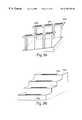
- F21W2111/027—Use or application of lighting devices or systems for signalling, marking or indicating, not provided for in codes F21W2102/00 – F21W2107/00 for roads, paths or the like for indicating kerbs, steps or stairs
- F—MECHANICAL ENGINEERING; LIGHTING; HEATING; WEAPONS; BLASTING
- F21—LIGHTING
- F21W—INDEXING SCHEME ASSOCIATED WITH SUBCLASSES F21K, F21L, F21S and F21V, RELATING TO USES OR APPLICATIONS OF LIGHTING DEVICES OR SYSTEMS
- F21W2111/00—Use or application of lighting devices or systems for signalling, marking or indicating, not provided for in codes F21W2102/00 – F21W2107/00
- F21W2111/08—Use or application of lighting devices or systems for signalling, marking or indicating, not provided for in codes F21W2102/00 – F21W2107/00 for handles or handrails
- F—MECHANICAL ENGINEERING; LIGHTING; HEATING; WEAPONS; BLASTING
- F21—LIGHTING
- F21Y—INDEXING SCHEME ASSOCIATED WITH SUBCLASSES F21K, F21L, F21S and F21V, RELATING TO THE FORM OR THE KIND OF THE LIGHT SOURCES OR OF THE COLOUR OF THE LIGHT EMITTED
- F21Y2105/00—Planar light sources
- F21Y2105/10—Planar light sources comprising a two-dimensional array of point-like light-generating elements
- F—MECHANICAL ENGINEERING; LIGHTING; HEATING; WEAPONS; BLASTING
- F21—LIGHTING
- F21Y—INDEXING SCHEME ASSOCIATED WITH SUBCLASSES F21K, F21L, F21S and F21V, RELATING TO THE FORM OR THE KIND OF THE LIGHT SOURCES OR OF THE COLOUR OF THE LIGHT EMITTED
- F21Y2115/00—Light-generating elements of semiconductor light sources
- F21Y2115/10—Light-emitting diodes [LED]
- G—PHYSICS
- G09—EDUCATION; CRYPTOGRAPHY; DISPLAY; ADVERTISING; SEALS
- G09G—ARRANGEMENTS OR CIRCUITS FOR CONTROL OF INDICATING DEVICES USING STATIC MEANS TO PRESENT VARIABLE INFORMATION
- G09G2300/00—Aspects of the constitution of display devices
- G09G2300/06—Passive matrix structure, i.e. with direct application of both column and row voltages to the light emitting or modulating elements, other than LCD or OLED
- G—PHYSICS
- G09—EDUCATION; CRYPTOGRAPHY; DISPLAY; ADVERTISING; SEALS
- G09G—ARRANGEMENTS OR CIRCUITS FOR CONTROL OF INDICATING DEVICES USING STATIC MEANS TO PRESENT VARIABLE INFORMATION
- G09G2320/00—Control of display operating conditions
- G09G2320/06—Adjustment of display parameters
- G09G2320/0626—Adjustment of display parameters for control of overall brightness
- G—PHYSICS
- G09—EDUCATION; CRYPTOGRAPHY; DISPLAY; ADVERTISING; SEALS
- G09G—ARRANGEMENTS OR CIRCUITS FOR CONTROL OF INDICATING DEVICES USING STATIC MEANS TO PRESENT VARIABLE INFORMATION
- G09G2320/00—Control of display operating conditions
- G09G2320/06—Adjustment of display parameters
- G09G2320/0666—Adjustment of display parameters for control of colour parameters, e.g. colour temperature
- G—PHYSICS
- G09—EDUCATION; CRYPTOGRAPHY; DISPLAY; ADVERTISING; SEALS
- G09G—ARRANGEMENTS OR CIRCUITS FOR CONTROL OF INDICATING DEVICES USING STATIC MEANS TO PRESENT VARIABLE INFORMATION
- G09G3/00—Control arrangements or circuits, of interest only in connection with visual indicators other than cathode-ray tubes
- G09G3/20—Control arrangements or circuits, of interest only in connection with visual indicators other than cathode-ray tubes for presentation of an assembly of a number of characters, e.g. a page, by composing the assembly by combination of individual elements arranged in a matrix no fixed position being assigned to or needed to be assigned to the individual characters or partial characters
- G09G3/22—Control arrangements or circuits, of interest only in connection with visual indicators other than cathode-ray tubes for presentation of an assembly of a number of characters, e.g. a page, by composing the assembly by combination of individual elements arranged in a matrix no fixed position being assigned to or needed to be assigned to the individual characters or partial characters using controlled light sources
- G09G3/30—Control arrangements or circuits, of interest only in connection with visual indicators other than cathode-ray tubes for presentation of an assembly of a number of characters, e.g. a page, by composing the assembly by combination of individual elements arranged in a matrix no fixed position being assigned to or needed to be assigned to the individual characters or partial characters using controlled light sources using electroluminescent panels
- G09G3/32—Control arrangements or circuits, of interest only in connection with visual indicators other than cathode-ray tubes for presentation of an assembly of a number of characters, e.g. a page, by composing the assembly by combination of individual elements arranged in a matrix no fixed position being assigned to or needed to be assigned to the individual characters or partial characters using controlled light sources using electroluminescent panels semiconductive, e.g. using light-emitting diodes [LED]
- G09G3/3208—Control arrangements or circuits, of interest only in connection with visual indicators other than cathode-ray tubes for presentation of an assembly of a number of characters, e.g. a page, by composing the assembly by combination of individual elements arranged in a matrix no fixed position being assigned to or needed to be assigned to the individual characters or partial characters using controlled light sources using electroluminescent panels semiconductive, e.g. using light-emitting diodes [LED] organic, e.g. using organic light-emitting diodes [OLED]
- G09G3/3275—Details of drivers for data electrodes
- G09G3/3283—Details of drivers for data electrodes in which the data driver supplies a variable data current for setting the current through, or the voltage across, the light-emitting elements
- H—ELECTRICITY
- H05—ELECTRIC TECHNIQUES NOT OTHERWISE PROVIDED FOR
- H05B—ELECTRIC HEATING; ELECTRIC LIGHT SOURCES NOT OTHERWISE PROVIDED FOR; CIRCUIT ARRANGEMENTS FOR ELECTRIC LIGHT SOURCES, IN GENERAL
- H05B45/00—Circuit arrangements for operating light-emitting diodes [LED]
- H05B45/30—Driver circuits
- H05B45/32—Pulse-control circuits
- H05B45/325—Pulse-width modulation [PWM]
- H—ELECTRICITY
- H05—ELECTRIC TECHNIQUES NOT OTHERWISE PROVIDED FOR
- H05B—ELECTRIC HEATING; ELECTRIC LIGHT SOURCES NOT OTHERWISE PROVIDED FOR; CIRCUIT ARRANGEMENTS FOR ELECTRIC LIGHT SOURCES, IN GENERAL
- H05B45/00—Circuit arrangements for operating light-emitting diodes [LED]
- H05B45/30—Driver circuits
- H05B45/37—Converter circuits
- H05B45/3725—Switched mode power supply [SMPS]
- H05B45/38—Switched mode power supply [SMPS] using boost topology
- Y—GENERAL TAGGING OF NEW TECHNOLOGICAL DEVELOPMENTS; GENERAL TAGGING OF CROSS-SECTIONAL TECHNOLOGIES SPANNING OVER SEVERAL SECTIONS OF THE IPC; TECHNICAL SUBJECTS COVERED BY FORMER USPC CROSS-REFERENCE ART COLLECTIONS [XRACs] AND DIGESTS
- Y02—TECHNOLOGIES OR APPLICATIONS FOR MITIGATION OR ADAPTATION AGAINST CLIMATE CHANGE
- Y02B—CLIMATE CHANGE MITIGATION TECHNOLOGIES RELATED TO BUILDINGS, e.g. HOUSING, HOUSE APPLIANCES OR RELATED END-USER APPLICATIONS
- Y02B20/00—Energy efficient lighting technologies, e.g. halogen lamps or gas discharge lamps
- Y02B20/30—Semiconductor lamps, e.g. solid state lamps [SSL] light emitting diodes [LED] or organic LED [OLED]
Definitions
- LEDsLight emitting diodes are known which, when disposed on a circuit, accept electrical impulses from the circuit and convert the impulses into light signals. LEDs are energy efficient, they give off virtually no heat, and they have a long lifetime.
- LEDsinclude air gap LEDs, GaAs light-emitting diodes (which may be doubled and packaged as single unit offer greater reliability than conventional single-diode package), polymer LEDs, and semi-conductor LEDs, among others.
- Most LEDs in current useare red.
- Conventional uses for LEDsinclude displays for low light environments, such as the flashing light on a modem or other computer component, or the digital display of a wristwatch. Improved LEDs have recently been used in arrays for longer-lasting traffic lights. LEDs have been used in scoreboards and other displays. Also, LEDs have been placed in arrays and used as television displays. Although most LEDs in use are red, yellow or white, LEDs may take any color; moreover, a single LED may be designed to change colors to any color in the color spectrum in response to changing electrical signals.
- Illumination systemsexist in which a network of individual lights is controlled by a central driver, which may be a computer-controlled driver. Such illumination systems include theatrical lighting systems.
- the USITT DMX-512 protocolwas developed to deliver a stream of data from a theatrical console to a series of theatrical lights.
- the DMX-512 protocolwas originally designed to standardize the control of light dimmers by lighting consoles.
- the DMX-512 protocolis a multiplexed digital lighting control protocol with a signal to control 512 devices, such device including dimmers, scrollers, non-dim relays, parameters of a moving light, or a graphical light in a computerized virtual reality set.
- DMX-512is used for control for a network of devices.
- the DMX-512 protocolemploys digital signal codes. When a transmitting device, such as a lighting console, sends digital codes, a receiving device, such as a dimmer, transforms these codes into a function command, such as dimming to a specified level. With digital systems, signal integrity is compromised less over long cable runs, relative to analog control. When a coded string of 0/1 digits are sent and received, the device will perform the desired task.
- DMX-512 protocol informationis transferred between devices over metal wires using the RS-485 hardware protocol.
- the first wireis referred to as a data + wire
- the second wireis referred to as a data ⁇ wire.
- the voltage used on the lineis typically positive five volts.
- to transmit a logical onethe data + wire is taken to positive five volts, and the data ⁇ wire to zero volts.
- To transmit a logical zerothe data + wire goes to zero volts, and the data ⁇ wire to positive five volts. This is quite different from the more common RS-232 interface, where one wire is always kept at zero volts.
- RS-232In RS-232, a logical one is transmitted by putting between positive six and positive twelve volts on the line, and a logical zero is transmitted by putting a voltage between negative six and negative twelve volts onto the line.
- RS-485is generally understood to be better for data transmission than RS-232. With RS-232, the receiver has to measure if the incoming voltage is positive or negative. With RS-485, the receiver only needs to determine which line has the higher voltage on it.
- the two wires over which RS-485 is transmittedare preferably twisted. Twisting means that disturbances on the line tend to affect both lines simultaneously, more or less by the same amount, so that the voltage on both lines will fluctuate, but the difference in voltage between the lines remains the same. The result is that noise is rejected from the line. Also, the drive capability of RS-485 drivers is higher than RS-232 drivers. As a result, the RS-485 protocol can connect devices over distances hundreds of times further than would be possible when using RS-232. RS-485 also increases the maximum data rate, i.e., the maximum amount of data which can be transmitted over the line every second. Communication between devices using RS-232 is normally about nine thousand six hundred baud (bits per second).
- DMX-512(using RS-485) permits data to be sent at two hundred fifty thousand baud (two hundred fifty thousand bits per second) over distances of hundreds of meters without problems. Every byte transmitted has one start bit, which is used to warn the receiver that the next character is starting, eight data bits (this conveys up to two hundred fifty six different levels) and two stop bits, which are used to tell the receiver that this is the end of the character. This means that every byte is transmitted as eleven bits, so that the length of each character is forty-four micro seconds.
- the receiverlooks at the two incoming signals on a pair of pins and compares the differences. A voltage rise on one wire and the inverse on the other will be seen as a differential and therefore deciphered as a digit. When both signals are identical, no difference is recognized and no digit deciphered. If interference was accidently transmitted along the line, it would impart no response as long as the interference was identical on both lines. The proximity of the two lines assist in assuring that distribution of interference is identical on both wires.
- the signal driversends five hundred twelve device codes in a continual, repetitive stream of data. The receiving device is addressed with a number between one and five hundred twelve so it will respond only to data that corresponds to its assigned address.
- a terminator resistoris typically installed at the end of a DMX line of devices, which reduces the possibility of signal reflection which can create errors in the DMX signal.
- the ohm value of the resistoris determined by the cable type used. Some devices allow for self termination at the end of the line.
- Multiple lines of DMX datacan be distributed through an opto-repeater. This device creates a physical break in the line by transforming the electrical signals into light which spans a gap, then it is restored to electrical signals. This protects devices from damaging high voltage, accidentally travelling along the network. It will also repeat the original DMX data to several output lines. The input data is recreated at the outputs, eliminating distortion. The signal leaves the opto-repeater as strong as it left the console.
- DMX messagesare typically generated through computer software. Each DMX message is preceded with a “break,” which is a signal for the receiver that the previous message has ended and the next message is about to start.
- the length of the break signal(equivalent to a logical zero on the line) has to be eighty-eight micro seconds according to the DMX specification. The signal can be more than eighty-eight micro seconds.
- MABMark After the Mark comes the first character, or byte, which is knows as the “Start” character.
- This characteris rather loosely specified, and is normally set to the value zero (it can vary between zero and two hundred fifty five).
- This start charactermay be used to specify special messages. It is, for example, possible to have five hundred twelve dimmers which respond to messages with the start character set to zero, and another five hundred twelve dimmers which respond to messages with the start character set to one. If one transmits data for these one thousand twenty-four dimmers, and one sets the start character to zero for the first five hundred twelve dimmers, and to one for the second set of five hundred twelve dimmers, it is possible to control one thousand twenty four dimmers (or more if one wishes, using the same technique).
- the disadvantageis a reduction in the number of messages sent to each of the set of dimmers, in this example by a factor two.
- the start characterthere are between one and five hundred twelve characters, which normally correspond to the up to five hundred twelve channels controlled by DMX. Each of these characters may have a value between zero (for ‘off’, zero percent) and two hundred fifty five (for full, one hundred percent). After the last character there may be another delay (at logic one level) before the next break starts.
- the number of messages which are transmitted every secondare dependent on all the parameters listed above. In one case, where the break length is eighty-eight microseconds, the make after break length is eight micro seconds, and each character takes exactly forty-four micro seconds to transmit there will be forty-four messages per second, assuming that all five hundred twelve channels are being transmitted.
- a significant problem with present lighting networksis that they require special wiring or cabling.
- one set of wiresis needed for electrical power, while a second set of wires is needed for data, such as DMX-512 protocol data.
- the owner of an existing set of lightsmust undertake significant effort to rewire in order to have a digitally controlled lighting environment.
- a second significant problem with present lighting networksis that particular lighting applications require particular lighting types. For example, LED based lights are appropriate for some applications, while incandescent lamps or halogen lamps may be more appropriate for other applications.
- a user who wishes to have a digitally controlled network of lights, in addition to rewiring,must currently add additional fixtures or replace old fixtures for each different type of light. Accordingly, a need has arisen for a lighting fixture that permits use of different types of digitally controlled lights.
- pulse width modulated signalsto control electrical devices, such as motors
- Traditional methods of providing pulse width modulated signalsinclude hardware using software programmed timers, which in some instances is not cost effective if not enough timer modules are available, and one interrupt per count processes, in which a microprocessor receives periodic interrupts at a known rate. Each time through the interrupt loop the processor compares the current count with the target counts and updates one or more output pins, thus creating a pulse width modulated signal, or PWM. In this case, the speed equals the clock speed divided by cycles in the interrupt routine divided by desired resolution.
- software loopscontain a variable number of instructions.
- the processoruses the hardware timer to generate a periodic interrupt, and then, depending on whether the pulse is to be very short or not, either schedules another interrupt to finish the PWM cycle, or creates the pulse by itself in the first interrupt routine by executing a series of instructions consuming a desired amount of time between two PWM signal updates.
- the difficulty with the third methodis that for multiple PWM channels it is very difficult to arrange the timer based signal updates such that they do not overlap, and then to accurately change the update times for a new value of PWM signals. Accordingly, a new pulse width modulation method and system is needed to assisting in controlling electrical devices.
- Illumination methods and systemsare provided herein that overcome many of the drawbacks of conventional illumination systems.
- methods and systemsare provided for multicolored illumination.
- the present inventionis an apparatus for providing an efficient, computer-controlled, multicolored illumination network capable of high performance and rapid color selection and change.
- a current control for a lighting assemblywhich may be an LED system or LED lighting assembly, which may be a pulse width modulated (“PWM”) current control or other form of current control where each current-controlled unit is uniquely addressable and capable of receiving illumination color information on a computer lighting network.
- PWMpulse width modulated
- current controlmeans PWM current control, analog current control, digital current control, and any other method or system for controlling current.
- the term “LED system”means any system that is capable of receiving an electrical signal and producing a color of light in response to the signal.
- the term “LED system”should be understood to include light emitting diodes of all types, light emitting polymers, semiconductor dies that produce light in response to current, organic LEDs, electro-luminescent strips, and other such systems.
- an “LED system”may refer to a single light emitting diode having multiple semiconductor dies that are individually controlled.
- illumination sourceshould be understood to include all illumination sources, including LED systems, as well as incandescent sources, including filament lamps, pyro-luminescent sources, such as flames, candle-luminescent sources, such as gas mantles and carbon arch radiation sources, as well as photo-luminescent sources, including gaseous discharges, fluorescent sources, phosphorescence sources, lasers, electro-luminescent sources, such as electro-luminescent lamps, light emitting diodes, and cathode luminescent sources using electronic satiation, as well as miscellaneous luminescent sources including galvano-luminescent sources, crystallo-luminescent sources, kine-luminescent sources, thermo-luminescent sources, triboluminescent sources, sonoluminescent sources, and radioluminescent sources.
- Illumination sourcesmay also include luminescent polymers capable of producing primary colors.
- the term “illuminate”should be understood to refer to the production of a frequency of radiation by an illumination source.
- the term “color”should be understood to refer to any frequency of radiation within a spectrum; that is, a “color,” as used herein, should be understood to encompass frequencies not only of the visible spectrum, but also frequencies in the infrared and ultraviolet areas of the spectrum, and in other areas of the electromagnetic spectrum.
- the inventionincludes a tree network configuration of lighting units (nodes).
- the present inventioncomprises a heat dissipating housing, made out of a heat-conductive material, for housing the lighting assembly.
- the heat dissipating housingcontains two stacked circuit boards holding respectively a power module and a light module.
- the LED boardis thermally connected to a separate heat spreader plate by means of a thermally conductive polymer and fasteners and should be considered substantially the same as an LED board with metal in center.
- the light moduleis adapted to be conveniently interchanged with other light modules having programmable current, and hence maximum light intensity, ratings.
- Such other light modulesmay include organic LEDs, electro-luminescent strips, and other modules, in addition to conventional LEDs.
- Other embodiments of the present inventioninvolve novel applications for the general principles described herein.
- a high performance computer controlled multicolored lighting networkwhich may be an LED lighting network.
- a LED lighting network structurecapable of both a linear chain of nodes and a tree configuration.
- a heat-dissipating housingto contain the lighting units of the lighting network.
- a current-regulated LED lighting apparatuswherein the apparatus contains lighting modules each having its own maximum current rating and each conveniently interchangeable with one another.
- a computer current-controlled LED lighting assemblyfor use as a general illumination device capable of emitting multiple colors in a continuously programmable twenty-four-bit spectrum.
- a flashlight, inclinometer, thermometer, general environmental indicator and lightbulball utilizing the general computer current-control principles of the present invention.
- the present inventionprovides applications for digitally controlled LED based lights.
- Systems and methods of the present inventioninclude uses of such lights in a number of technical fields in which illumination technology is critical.
- Systems and methods of the present inventioninclude systems whereby such lights may be made responsive to a variety of different signals.
- Systems and methods of the present inventioninclude improved data and power distribution networks.
- LEDsare used as part of or on a wide range of items to provide aesthetically appealing or function effects.
- the digitally controlled light emitting diodes (LEDs) of the present inventionmay be used in a number of technological fields in inventions more particularly described below.
- a track having a plurality of conducting wiresmay include a driver for delivering slewed data to the track.
- a housing for the trackmay be a plurality of devices disposed on the housing and connected to the track.
- the devicesmay be illumination devices or other devices that are compatible with the RS-485 standard.
- the devicesmay include an LED system that is controlled by a processor.
- the drivermay be capable of controlling a transition signal between a state representing a logical one and a state representing a logical zero.
- a terminator for the trackfor absorbing excess energy in the track.
- the terminatormay include a bridge rectifier and/or a shunt regulator.
- a track headwhich electrically attaches to both power and signal conductors of the track.
- a track having a plurality of conducting wiresmay include a track having a plurality of conducting wires, a housing for the track, a driver, for delivering data to the track, the driver capable of controlling a transition signal between a state representing a logical one and a state representing a logical zero, and a plurality of devices disposed on the housing and connected to the track, the devices being compatible with the RS-485 standard, wherein the devices include an LED system designed to be controlled by a processor.
- FIG. 1depicts a light module of the present invention.
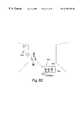
- FIG. 2depicts a light module of FIG. 1 in data connection with a generator of control data for the light module.
- FIG. 3depicts a schematic of an embodiment of light module.
- FIG. 4depicts an array of LEDs in an embodiment of a light module.
- FIG. 5depicts a power module in an embodiment of the invention.
- FIG. 6depicts a circuit design for an embodiment of a light module.
- FIG. 7depicts a circuit design for an array of LEDs in a light module in an embodiment of the invention.
- FIG. 8depicts an array of LEDs that may be associated with a circuit such as that of FIG. 6 .
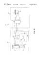
- FIG. 9depicts a schematic of the electrical design of an embodiment of a light module.
- FIG. 10depicts a power module for a light module of the invention.
- FIG. 11depicts another view of the power module of FIG. 10 .
- FIG. 12depicts a circuit for a power supply for a light module of the invention.
- FIG. 13depicts a circuit for a power/data multiplexor.
- FIG. 14depicts a circuit for another embodiment of a power/data multiplexor.
- FIG. 15depicts flow charts depicting steps in a modified pulse width modulation software routine.
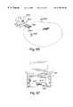
- FIG. 16depicts a data delivery track lighting system.
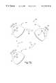
- FIG. 17depicts a circuit design for a data driver for the track system of FIG. 16 .
- FIG. 18depicts a circuit design for a terminator for a track system of FIG. 16 .
- FIG. 19depicts an embodiment of a light module in which a cylindrical housing houses the light module.
- FIG. 20depicts a modular light module.
- FIG. 21depicts a modular light module constructed to fit a halogen socket.
- FIG. 22depicts a circuit design for an embodiment of a light module.
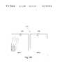
- FIG. 23depicts a modular housing for a light module.
- FIG. 24is a schematic illustration of a modular LED unit in accordance with one embodiment of the present invention.
- FIG. 25illustrates a light module in accordance with one embodiment of the present invention.
- FIG. 26illustrates a light module in accordance with another embodiment of the present invention.
- FIG. 27illustrates a light module in accordance with a further embodiment of the present invention.
- FIGS. 28A-Cillustrate a plurality of LEDs arranged within the various configurations for use with the modular LED unit of the present invention.
- FIGS. 29-68illustrate the various environments within which the modular LED unit of the present invention may illuminate.
- FIG. 69depicts a smart light bulb embodiment of the invention.
- FIG. 70depicts the embodiment of FIG. 69 in data connection with another device.
- FIG. 71depicts the embodiment of FIG. 69 in connection with other smart light bulbs.
- FIG. 72depicts a network of smart light bulbs in data connection with each other.
- FIG. 73depicts a light buffer sensor/feedback application using a smart light bulb.
- FIG. 74depicts an EKG sensor/feedback environment using a smart light bulb.
- FIG. 75depicts a schematic diagram of a sensor/feedback application.
- FIG. 76depicts a general block diagram relevant to a color thermometer.
- FIG. 77depicts a color speedometer.
- FIG. 78depicts a color inclinometer.
- FIG. 79depicts a color magnometer.
- FIG. 80depicts a smoke alert system.
- FIG. 81depicts a color pH meter.
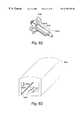
- FIG. 82depicts a security system to indicate the presence of an object.
- FIG. 83depicts an electromagnetic radiation detector.
- FIG. 84depicts a color telephone indicator.
- FIG. 85depicts a lighting system using a light module of the present invention in association with an entertainment device.
- FIG. 86depicts a schematic of the system of FIG. 85 .
- FIG. 87depicts a schematic of an encoder for the system of FIG. 85 .
- FIG. 88depicts a schematic of an encoding method using the encoder of FIG. 87 .
- FIG. 89depicts a schematic of a decoder of the system of FIG. 85 .
- FIG. 90Adepicts an embodiment of a system for precision illumination.
- FIG. 90Bdepicts a block diagram of a control module for the precision illumination system of FIG. 90 A.
- FIG. 91depicts an embodiment comprising a precision illumination system held in an operator's hand.
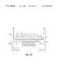
- FIG. 92Adepicts fruit-bearing plants illuminated by an array of LED systems.
- FIG. 92Bdepicts fruit-bearing plants illuminated by natural light.
- FIG. 93Ais a generally schematic view illustrating the anatomy of the porta hepatis as illuminated by an embodiment of an LED system affixed to a medical instrument.
- FIG. 93Bdepicts an embodiment of an LED system affixed to a medical instrument.
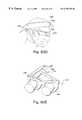
- FIG. 93Cdepicts an embodiment of an LED system affixed to an endoscope.
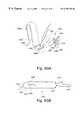
- FIG. 93Ddepicts an embodiment of an LED system affixed to a surgical headlamp.
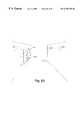
- FIG. 93Edepicts an embodiment of an LED system affixed to surgical loupes.
- FIG. 94depicts a method for treating a medical condition by illuminating with an embodiment of an LED system.
- FIG. 95depicts changing the perceived color of colored objects by changing the color of the light projected thereon.
- FIG. 96depicts creating an illusion of motion in a colored design by changing the color of the light projected thereon.
- FIG. 97depicts a vending machine in which an illusion of motion in a colored design is created by changing the color of the light projected thereon.
- FIG. 98depicts a vending machine in which objects appear and disappear in a colored design by changing the color of the light projected thereon.
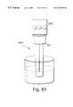
- FIG. 99depicts a system for illuminating a container.
- FIG. 100depicts an article of clothing lit by an LED system.
- a light module 100is depicted in block diagram format.
- the light module 100includes two components, a processor 16 and an LED system 120 , which is depicted in FIG. 1 as an array of light emitting diodes.
- the term “processor”is used herein to refer to any method or system for processing in response to a signal or data and should be understood to encompass microprocessors, integrated circuits, computer software, computer hardware, electrical circuits, application specific integrated circuits, personal computers, chips, and other devices capable of providing processing functions.
- the LED system 120is controlled by the processor 16 to produce controlled illumination.
- the processor 16controls the intensity of different color individual LEDs, semiconductor dies, or the like of the LED system 120 to produce illumination in any color in the spectrum.
- Instantaneous changes in color, strobing and other effects, more particularly described below,can be produced with light modules such as the light module 100 depicted in FIG. 1 .
- the light module 100may be made capable of receiving power and data.
- the light module 100through the processor 16 , may be made to provide the various functions ascribed to the various embodiments of the invention disclosed herein.
- the light module 100may be constructed to be used either alone or as part of a set of such light modules 100 .
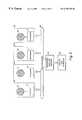
- An individual light module 100 or a set of light modules 100can be provided with a data connection 500 to one or more external devices, or, in certain embodiments of the invention, with other light modules 100 .
- the term “data connection”should be understood to encompass any system for delivering data, such as a network, a data bus, a wire, a transmitter and receiver, a circuit, a video tape, a compact disc, a DVD disc, a video tape, an audio tape, a computer tape, a card, or the like.
- a data connectionmay thus include any system of method to deliver data by radio frequency, ultrasonic, auditory, infrared, optical, microwave, laser, electromagnetic, or other transmission or connection method or system. That is, any use of the electromagnetic spectrum or other energy transmission mechanism could provide a data connection as disclosed herein.
- the light module 100may be equipped with a transmitter, receiver, or both to facilitate communication, and the processor 16 may be programmed to control the communication capabilities in a conventional manner.
- the light modules 100may receive data over the data connection 500 from a transmitter 502 , which may be a conventional transmitter of a communications signal, or may be part of a circuit or network connected to the light module 100 .
- the transmitter 502should be understood to encompass any device or method for transmitting data to the light module 100 .
- the transmitter 502may be linked to or be part of a control device 504 that generates control data for controlling the light modules 100 .
- the control device 504is a computer, such as a laptop computer.
- the control datamay be in any form suitable for controlling the processor 16 to control the LED system 120 .
- the control datais formatted according to the DMX-512 protocol, and conventional software for generating DMX-512 instructions is used on a laptop or personal computer as the control device 504 to control the light modules 100 .
- the light module 100may also be provided with memory for storing instructions to control the processor 16 , so that the light module 100 may act in stand alone mode according to pre-programmed instructions.
- FIG. 3shown is an electrical schematic representation of the light module 100 in one embodiment of the present invention.
- FIGS. 4 and 5show the LED-containing side and the electrical connector side of an exemplary embodiment of such a light module 100 .
- Light module 100may be constructed, in an embodiment, as a self-contained module that is configured to be a standard item interchangeable with any similarly constructed light module.
- Light module 100contains a ten-pin electrical connector 110 of the general type.
- the connector 110contains male pins adapted to fit into a complementary ten-pin connector female assembly, to be described below.
- Pin 180is the power supply.
- a source of DC electrical potentialenters light module 100 on pin 180 .
- Pin 180is electrically connected to the anode end of light emitting diode (LED) sets 120 , 140 and 160 to establish a uniform high potential on each anode end.
- LEDlight emitting diode
- LED system 120includes a set 121 of red LEDs, a set 140 of blue LEDs, and a set 160 of green LEDs.
- the LEDsmay be conventional LEDs, such those obtainable from the Nichia America Corporation. These LEDs are primary colors, in the sense that such colors when combined in preselected proportions can generate any color in the spectrum. While use of three primary colors is preferred, it will be understood that the present invention will function nearly as well with only two primary colors to generate a wide variety of colors in the spectrum. Likewise, while the different primary colors are arranged herein on sets of uniformly colored LEDS, it will be appreciated that the same effect may be achieved with single LEDs containing multiple color-emitting semiconductor dies.
- LED sets 121 , 140 and 160each preferably contains a serial/parallel array of LEDs in the manner described by Okuno in U.S. Pat. No. 4,298,869, incorporated herein by reference.
- LED system 120includes LED set 121 , which contains three parallel connected rows of nine red LEDs (not shown), as well as LED sets 140 and 160 , which each contain five parallel connected rows of five blue and green LEDS, respectively (not shown). It is understood by those in the art that, in general, each red LED drops the potential in the line by a lower amount than each blue or green LED, about two and one-tenth V, compared to four volts, respectively, which accounts for the different row lengths.
- the number of LEDs in each rowis determined by the amount of voltage drop desired between the anode end at the power supply voltage and the cathode end of the last LED in the row.
- the parallel arrangement of rowsis a fail-safe measure that ensures that the light module 100 will still function even if a single LED in a row fails, thus opening the electrical circuit in that row.
- the cathode ends of the three parallel rows of nine red LEDs in LED set 121are then connected in common, and go to pin 128 on connector 110 .
- the cathode ends of the five parallel rows of five blue LEDs in LED set 140are connected in common, and go to pin 148 on connector 110 .
- each LED set in the LED system 120is associated with a programming resistor that combines with other components, described below, to program the maximum current through each set of LEDS.
- resistor 122Between pin 124 and 126 is resistor 122 , six and two-tenths ohms. Between pin 144 and 146 is resistor 142 , four and seven-tenths ohms. Between pin 164 and 166 is resistor 162 , four and seven-tenths ohms.
- Resistor 122programs maximum current through red LED set 121
- resistor 142programs maximum current through blue LED set 140
- resistor 162programs maximum current through green LED set 160 .
- the values these resistors should takeare determined empirically, based on the desired maximum light intensity of each LED set. In the embodiment depicted in FIG. 3, the resistances above program red, blue and green currents of seventy, fifty and fifty mA, respectively.
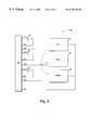
- a circuit 10 for a digitally controlled LED-based lightincludes an LED assembly 12 containing LED output channels 14 , which are controlled by the processor 16 . Data and power are fed to the circuit 10 via power and data input unit 18 .
- the address for the processor 16is set by switch unit 20 containing switches which are connected to individual pins of pin set 21 of processor 16 .
- An oscillator 19provides a clock signal for processor 16 via pins 9 and 10 of the same.
- data and power input unit 18has four pins, including a power supply 1 , which may be a twenty-four volt LED power supply, a processor power supply 2 , which may be a five volt processor power supply, a data in line 3 and a ground pin 4 .
- the first power supply 1provides power to LED channels 14 of LED assembly 12 .
- the second processor power supply 2may be connected to power supply input 20 of processor 16 to provide operating power for the processor 16 and also may be connected to a pin 1 of the processor 16 to tie the reset high.
- a capacitor 24such as a one-tenth microfarad capacitor, may be connected between the processor power supply 2 and ground.
- the data line 3may be connected to pin 18 of processor 16 and may be used to program and dynamically control the processor 16 .
- the groundmay be connected to pins 8 and 19 of the processor 16 .
- LED assembly 12may be supplied with power from the LED power supply 1 and may contain a transistor-controlled LED channel 14 .
- the LED channel 14may supply power to at least one LED.
- the LED assembly 12may supply multiple LED channels 14 for different color LEDs (e.g., red, green and blue), with each LED channel 14 individually controlled by a transistor 26 .
- LEDs 15may be arrayed in series to receive signals through each of the LED channels 14 .
- a series of LEDs of each different colorred, green and blue
- LEDs 15may also be arrayed to receive data according to a protocol such as the DMX-512 protocol, so that many individual LEDs 15 may be controlled through programming the processor 16 .
- gates of transistors 26are controlled by processor 16 to thereby control operation of the LED channels 14 and the LEDs 15 .
- the output of the microprocessorappears on pins 12 , 13 and 14 of processor 16 , which are then connected to the gates of the LED channels 14 of the LEDs 15 .
- Additional pins of processor 16could be used to control additional LEDs.
- different pins of processor 16could be used to control the illustrated LEDs 15 , provided that appropriate modifications were made to the instructions controlling operation of processor 16 .
- a resistor 28may be connected between transistor 26 and ground.
- resistor 28 associated with the red LEDhas a resistance value of sixty-two ohms, and the resistors associated with the green and blue LEDs each have a resistance of ninety ohms.
- a capacitor 29may be connected between the first LED power supply 1 and ground. In the illustrated embodiment, this capacitor has a value of one-tenth of a microfarad.
- Processor 16may be connected to an oscillator 19 .
- One acceptable oscillatoris a crystal tank circuit oscillator which provides a twenty megaHertz clock. This oscillator may be connected to pins 9 and 10 of processor 16 . It is also possible to use an alternative oscillator. Primary considerations associated with selection of an oscillator are consistency, operating speed and cost.
- processor 16is a programmable integrated circuit, or PIC chip, such as a PIC 16C63 or PIC 16C66 manufactured by Microchip Technology, Inc.
- PIC 16C6X series PIC chipwhich includes both the PIC 16C63 and PIC 16C66
- a complete description of the PIC 16C6X series PIC chipis attached to the U.S. Provisional Patent Application filed on Dec. 17, 1997, entitled Digitally Controlled Light Emitting Diode Systems and Methods, to Mueller and Lys, and is incorporated by reference herein.
- the PIC 16C66is currently the preferred microprocessor, any processor capable of controlling the LEDs 15 of LED assembly 12 may be used.
- an application specific integrated circuit (ASIC)may be used instead of processor 16 .
- ASICapplication specific integrated circuit
- other commercially available processorsmay also be used without departing from this invention.
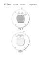
- a total of eighteen LEDs 15are placed in three series according to color, and the series are arranged to form a substantially circular array 37 .
- the processor 16can be used to separately control the precise intensity of each color series of the LEDs 15 , so that any color combination, and thus any color, can be produced by the array 37 .
- the responsiveness of LEDs to changing electrical signalspermits computer control of the LEDs via control of the electrical impulses delivered to the LEDs.
- the usermay precisely control the color and intensity of the LED. Due to the relatively instantaneous response of LEDs to changes in electrical impulses, the color and intensity state of an LED may be varied quite rapidly by changes in such impulses.
- the processor 16may be controlled by conventional means, such as a computer program, to send the appropriate electrical signals to the appropriate LED at any given time.
- the controlmay be digital, so that precise control is possible. Thus, overall lighting conditions may be varied in a highly controlled manner.
- FIGS. 10 and 11show the power terminal side and electrical connector side of an embodiment of power module 200 .
- power module 200may be self contained. Interconnection with a male pin set 110 is achieved through complementary female pin set 210 .
- Pin 280connects with pin 180 for supplying power, delivered to pin 280 from supply 300 .
- Supply 300is shown as a functional block for simplicity. In actuality, supply 300 can take numerous forms for generating a DC voltage.
- supply 300provides twenty-four volts through a connection terminal (not shown), coupled to pin 280 through transient protection capacitors (not shown) of the general type. It will be appreciated that supply 300 may also supply a DC voltage after rectification and/or voltage transformation of an AC supply, as described more fully in U.S. Pat. No. 4,298,869.
- ICR 220Also connected to pin connector 210 are three current programming integrated circuits, ICR 220 , ICB 240 and ICG 260 .
- Each of thesemay be a three terminal adjustable regulator, such as part number LM317B, available from the National Semiconductor Corporation, Santa Clara, Calif. The teachings of the LM317 datasheet are incorporated herein by reference.
- Each regulatorcontains an input terminal, an output terminal and an adjustment terminal, labeled I, O, and A, respectively.
- the regulatorsfunction to maintain a constant maximum current into the input terminal and out of the output terminal. This maximum current is pre-programmed by setting a resistance between the output and the adjustment terminals.
- ICR 220current enters the input terminal of ICR 220 from pin 228 .
- Pin 228 in the power moduleis coupled to pin 128 in the light module and receives current directly from the cathode end of the red LED system 121 .
- resistor 122is ordinarily disposed between the output and adjustment terminals of ICR 220 through pins 224 / 124 and 226 / 126 , resistor 122 programs the amount of current regulated by ICR 220 .
- ICR 220Eventually, the current output from the adjustment terminal of ICR 220 enters a Darlington driver. In this way, ICR 220 and associated resistor 122 program the maximum current through red LED system 120 . Similar results are achieved with ICB 240 and resistor 142 for blue LED set 140 , and with ICG 260 and resistor 162 for green LED set 160 .
- ICI 380may be a high current/voltage Darlington driver, such as part no. DS2003, available from the National Semiconductor Corporation, Santa Clara, Calif. ICI 380 may be used as a current sink, and may function to switch current between respective LED sets and ground 390 . As described in the DS2003 datasheet, incorporated herein by reference, ICI contains six sets of Darlington transistors with appropriate on-board biasing resistors.
- nodes 324 , 344 and 364couple the current from the respective LED sets to three pairs of these Darlington transistors, in the well known manner to take advantage of the fact that the current rating of ICI 380 may be doubled by using pairs of Darlington transistors to sink respective currents.
- Each of the three on-board Darlington pairsis used in the following manner as a switch.
- the base of each Darlington pairis coupled to signal inputs 424 , 444 and 464 , respectively.
- input 424is the signal input for switching current through node 324 , and thus the red LED set 121 .
- Input 444is the signal input for switching current though node 344 , and thus the blue LED set 140 .
- Input 464is the signal input for switching current through node 364 , and thus the green LED set 160 .
- Signal inputs 424 , 444 and 464are coupled to respective signal outputs 434 , 454 and 474 on microcontroller IC 2 400 , as described below.
- ICI 380switches current through a respective node with the identical frequency and duty cycle.
- the states of signal inputs 424 , 444 and 464directly correlate with the opening and closing of the power circuit through respective LED sets 121 , 140 and 160 .
- Microcontroller IC 2 400is preferably a MICROCHIP brand PIC16C63, although almost any properly programmed microcontroller or microprocessor can perform the software functions described herein.
- the main function of microcontroller IC 2 400is to convert numerical data received on serial Rx pin 520 into three independent high frequency square waves of uniform frequency but independent duty cycles on signal output pins 434 , 454 and 474 .
- the FIG. 9 representation of microcontroller IC 2 400is partially stylized, in that persons of skill in the art will appreciate that certain of the twenty-eight standard pins have been omitted or combined for greatest clarity. Further detail as to a similar microcontroller is provided in connection with FIG. 12 for another embodiment of the invention.
- Microcontroller IC 2 400is powered through pin 450 , which is coupled to a five volt source of DC power 700 .
- Source 700is preferably driven from supply 300 through a coupling (not shown) that includes a voltage regulator (not shown).
- An exemplary voltage regulatoris the LM340 3-terminal positive regulator, available from the National Semiconductor Corporation, Santa Clara, Calif. The teachings of the LM340 datasheet are hereby incorporated by reference. Those of skill in the art will appreciate that most microcontrollers, and many other independently powered digital integrated circuits, are rated for no more than a five volt power source.
- the clock frequency of microcontroller IC 2 400is set by crystal 480 , coupled through appropriate pins.
- Pin 490is the microcontroller IC 2 400 ground reference.
- Switch 600is a twelve position dip switch that may be alterably and mechanically set to uniquely identify the microcontroller IC 2 400 .
- a pathis generated from corresponding pins 650 on microcontroller IC 2 400 to ground 690 .
- Twelve switchescreate twenty-four possible settings, allowing any microcontroller IC 2 400 to take on one of four thousand ninety-six different IDs, or addresses. In the embodiment of FIG. 9, only nine switches are actually used because the DMX-512 protocol is employed.
- microcontroller IC 2 400“knows” its unique address (“who am I”), and “listens” on serial line 520 for a data stream specifically addressed to it.
- a high speed network protocolsuch as a DMX protocol, may be used to address network data to each individually addressed microcontroller IC 2 400 from a central network controller (not shown).
- the DMX protocolis described in a United States Theatre Technology, Inc. publication entitled “DMX512/1990 Digital Data Transmission Standard for Dimmers and Controllers,” incorporated herein by reference.
- a central controller(not shown) creates a stream of network data consisting of sequential data packets.
- Each packetfirst contains a header, which is checked for conformance to the standard and discarded, followed by a stream of sequential characters representing data for sequentially addressed devices. For instance, if the data packet is intended for light number fifteen, then fourteen characters from the data stream will be discarded, and the device will save character number fifteen. If as in the preferred embodiment, more than one character is needed, then the address is considered to be a starting address, and more than one character is saved and utilized. Each character corresponds to a decimal number zero to two hundred fifty-five, linearly representing the desired intensity from Off to Full.
- each of the three LED colorsis assigned a discrete intensity value between zero and two hundred fifty-five. These respective intensity values are stored in respective registers within the memory of microcontroller IC 2 400 (not shown).
- the refresh cycleis defined by the standard to be a minimum of one thousand one hundred ninety-six microseconds, and a maximum of one second.
- Microcontroller IC 2 400is programmed continually to “listen” for its data stream. When microcontroller IC 2 400 is “listening,” but before it detects a data packet intended for it, it is running a routine designed to create the square wave signal outputs on pins 434 , 454 and 474 .
- the values in the color registersdetermine the duty cycle of the square wave. Since each register can take on a value from zero to two hundred fifty five, these values create two hundred fifty six possible different duty cycles in a linear range from zero percent to one hundred percent. Since the square wave frequency is uniform and determined by the program running in the microcontroller IC 2 400 , these different discrete duty cycles represent variations in the width of the square wave pulses. This is known as pulse width modulation (PWM).
- PWMpulse width modulation
- the PWM interrupt routineis implemented using a simple counter, incrementing from zero to two hundred fifty-five in a cycle during each period of the square wave output on pins 434 , 454 and 474 .
- the counterrolls over to zero, all three signals are set high.
- the counterequals the register value, signal output is changed to low.
- microcontroller IC 2 400receives new data, it freezes the counter, copies the new data to the working registers, compares the new register values with the current count and updates the output pins accordingly, and then restarts the counter exactly where it left off.
- intensity valuesmay be updated in the middle of the PWM cycle. Freezing the counter and simultaneously updating the signal outputs has at least two advantages.
- each lighting unitto quickly pulse/strobe as a strobe light does.
- strobinghappens when the central controller sends network data having high intensity values alternately with network data having zero intensity values at a rapid rate. If one restarted the counter without first updating the signal outputs, then the human eye would be able to perceive the staggered deactivation of each individual color LED that is set at a different pulse width.
- This featureis not of concern in incandescent lights because of the integrating effect associated with the heating and cooling cycle of the illumination element.
- LEDSunlike incandescent elements, activate and deactivate essentially instantaneously in the present application.
- the second advantageis that one can “dim” the LEDs without the flickering that would otherwise occur if the counter were reset to zero.
- the central controllercan send a continuous dimming signal when it creates a sequence of intensity values representing a uniform and proportional decrease in light intensity for each color LED. If one did not update the output signals before restarting the counter, there is a possibility that a single color LED will go through nearly two cycles without experiencing the zero current state of its duty cycle. For instance, assume the red register is set at 4 and the counter is set at 3 when it is frozen. Here, the counter is frozen just before the “off part” of the PWM cycle is to occur for the red LEDS. Now assume that the network data changes the value in the red register from four to two and the counter is restarted without deactivating the output signal.
- the microprocessors that provide the digital control functions of the LEDs of the present inventionmay be responsive to any electrical signal; that is, external signals may be used to direct the microprocessors to control the LEDs in a desired manner.
- a computer programmay control such signals, so that a programmed response to given input signals is possible.
- signalsmay be generated that turn individual LEDs on and off, that vary the color of individual LEDs throughout the color spectrum, that strobe or flash LEDs at predetermined intervals that are controllable to very short time intervals, and that vary the intensity of light from a single LED or collection of LEDs.
- a variety of signal-generating devicesmay be used in accordance with the present invention to provide significant benefits to the user.
- Input signalscan range from simple on-off or intensity signals, such as that from a light switch or dial, or from a remote control, to signals from detectors, such as detectors of ambient temperature or light.
- detectorssuch as detectors of ambient temperature or light.
- the precise digital control of arrayed LEDs in response to a wide range of external signalspermits applications in a number of technological fields in accordance with the present invention.
- Jacks 800 and 900are standard RJ-45 network jacks.
- Jack 800is used as an input jack, and is shown for simplicity as having only three inputs: signal inputs 860 , 870 and ground 850 .
- Network dataenters jack 800 and passes through signal inputs 860 and 870 .
- IC 3 500which is an RS-485/RS-422 differential bus repeater of the standard type, preferably a DS96177 from the National Semiconductor Corporation, Santa Clara, Calif.
- the teachings of the DS96177 datasheetare hereby incorporated by reference.
- the signal inputs 860 , 870enter IC 3 500 at pins 560 , 570 .
- the data signalis passed through from pin 510 to pin 520 on microcontroller IC 2 400 .
- the same data signalis then returned from pin 540 on IC 2 400 to pin 530 on IC 3 500 .
- Jack 900is used as an output jack and is shown for simplicity as having only five outputs: signal outputs 960 , 970 , 980 , 990 and ground 950 .
- Outputs 960 and 970are split directly from input lines 860 and 870 , respectively.
- Outputs 980 and 990come directly from IC 3 500 pins 580 and 590 , respectively. It will be appreciated that the foregoing assembly enables two network nodes to be connected for receiving the network data.
- a networkmay be constructed as a daisy chain, if only single nodes are strung together, or as a tree, if two or more nodes are attached to the output of each single node.
- an addressable network of LED illumination or display unitscan be constructed from a collection of power modules each connected to a respective light module.
- any illumination or display colormay be generated simply by preselecting the light intensity that each color LED emits.
- each color LEDcan emit light at any of 255 different intensities, depending on the duty cycle of PWM square wave, with a full intensity generated by passing maximum current through the LED.
- the maximum intensitycan be conveniently programmed simply by adjusting the ceiling for the maximum allowable current using programming resistances for the current regulators residing on the light module. Light modules of different maximum current ratings may thereby be conveniently interchanged.
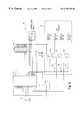
- a special power supply module 38is provided, as depicted in FIG. 12 .
- the power supply module 38may be disposed on any platform of the light module 100 , such as, for example, the platform of the embodiment depicted in FIGS. 4 and 5.
- the output of the power supply module 38supplies power to a power and data input, such as the power and data input 18 of the circuit 10 of FIG. 6 .
- the power supply module 38is capable of taking a voltage or current input in a variety of forms, including an intermittent input, and supplying a steady, clean source of power to the circuit 10 .
- the power supply moduleincludes inputs 40 , which may be incoming electrical signals that would typically be of alternating current type.
- Incoming signalsare then converted by a rectifying element 42 , which in an embodiment of the invention is a bridge rectifier consisting of four diodes 44 .
- the rectifying element 42rectifies the alternating current signal into a clean direct current signal.
- the power supply module 38may further include a storage element 48 , which may include one or more capacitors 50 .
- the storage elementstores power that is supplied by the rectifying element 42 , so that the power supply module 38 can supply power to the input 18 of the circuit 10 of FIG. 6, even if power to the input 40 of the power supply module 38 is intermittent.
- one of the capacitorsis an electrolytic capacitor with a value of three hundred thirty microfarads.
- the power supply module 38may further include a boost converter 52 .
- the boost convertertakes a low voltage direct current and boosts and cleans it to provide a higher voltage to the DC power input 18 of the circuit 10 of FIG. 6 .
- the boost converter 52may include an inductor 54 , a controller 58 , one or more capacitors 60 , one or more resistors 62 , and one or more diodes 64 .
- the resistorslimit the data voltage excursions in the signal to the processor of the circuit 10 .
- the controller 58may be a conventional controller suitable for boost conversion, such as the LTC1372 controller provided by Linear Technology Corporation. The teachings of the LTC1372 data sheet are incorporated by reference herein.
- the boost converter 52is capable of taking power at approximately ten volts and converting it to a clean power at twenty-four volts.
- the twenty-four volt powercan be used to power the circuit 10 and the LEDs 15 of FIG. 6 .
- power and dataare supplied to the circuit 10 and the LEDs 15 by conventional means, such as a conventional electrical wire or wires for power and a separate wire, such as the RS-485 wire, for data, as in most applications of the DMX-512 protocol.
- a separate data wiremay provide data to control the LEDs 15 , if the platform 30 is inserted into a conventional halogen fixture 34 that has only electrical power.
- electrical power and serial dataare simultaneously supplied to the device, which may be a lighting device such as the LED-based lighting device of FIG. 1 or may be any other device that requires both electrical power and data. Electrical power and data may be supplied to multiple lighting devices on a single pair of wires.
- poweris delivered to the device (and, where applicable, through the power supply module 38 ) along a two wire data bus such as the type normally used for lighting in applications where high power is required, such as halogen lamps.
- the power supply module 38recovers power from data lines.
- a power data multiplexer 60is provided, which amplifies an incoming data stream to produce logical data levels, with one or more of the logical states having sufficient voltage or current that power can be recovered during that logical state.
- a data input 64is provided, which may be a line driver or other input for providing data.
- the datais DMX-512 protocol data for control of lighting, such as LEDs. It should be understood that the power data multiplexer 60 could manipulate data according to other protocols and for control of other devices.
- the power data multiplexer 60may include a data input element 68 and a data output element 70 .
- the data output element 70may include an output element 72 that supplies combined power and data to a device, such as the power supply module 38 of FIG. 12, or the input 18 of the circuit 10 of FIG. 6 .
- the data input element 68may include a receiver 74 , which may be an RS-485 receiver for receiving DMX-512 data, or any other conventional receiver for receiving data according to a protocol.
- the data input element 68may further include a power supply 78 with a voltage regulator 80 , for providing regulated power to the receiver 74 and the data output element 70 .
- the data input element 68supplies a data signal to the data output element 70 .
- a TTL data signalis supplied.
- the data output element 70amplifies the data signal and determines the relative voltage direction of the output.
- a chip 82consists of a high speed PWM stepper motor driver chip that amplifies the data signal to a positive signal of twenty four volts to reflect a logical one and to negative signal of twenty four volts to reflect a logical zero. It should be understood that different voltages could be used to reflect logical ones and zeros. For example, zero volts could represent logical zero, with a particular positive or negative voltage representing a logical one.
- the voltageis sufficient to supply power while maintaining the logical data values of the data stream.
- the chip 82may be any conventional chip capable of taking an input signal and amplifying it in a selected direction to a larger voltage. It should be understood that any circuit for amplifying data while maintaining the logical value of the data stream may be used for the power data multiplexer 60 .
- FIGS. 12 and 13should be understood to encompass any devices for converting a data signal transmitted according to a data protocol, in which certain data are represented by nonzero signals in the protocol, into power that supplies an electrical device.
- the devicemay be a light module 100 , such as that depicted in FIG. 1 .
- the data supplied to the power data multiplexer 60is data according to the USITT DMX-512 protocol, in which a constant stream of data is transmitted from a console, such as a theatrical console, to all devices on the DMX-512 network.
- DMX-512 formatsare enforced upon the data. Because of this one can be assured that the power data multiplexer 60 , either in the embodiment depicted in FIG. 13, or in another embodiment, can amplify the DMX-512 signal from the standard signal voltage and/or electrical current levels to higher voltages, and usually higher electrical currents.
- the resulting higher power signal from the power data multiplexer 60can be converted back into separated power by the power supply module 38 , or by another circuit capable of providing rectification with a diode and filtering with a capacitor for the power.
- the data stream from the power data multiplexor 60can be recovered by simple resistive division, which will recover a standard data voltage level signal to be fed to the input 18 .
- Resistive divisioncan be accomplished by the resistors 84 of FIG. 12 .
- the power data multiplexer 62when combined with the power supply module 38 and the array 37 mounted on a modular platform 30 , permits the installation of LED-based, digitally controlled lighting using already existing wires and fixtures. As the system permits the device to obtain power and data from a single pair of wires, no separate data or power wires are required.
- the power data multiplexor 60can be installed along a conventional data wire, and the power supply module 38 can be installed on the platform 30 .
- the usercan have LED based, digitally controlled lights by supplying DMX-512 data to the power data multiplexor 60 .
- the power supply module 38can be supplied with standard twelve volt alternating current in a non-modified manner. That is, the power supply module can supply the array 37 from alternating current present in conventional fixtures, such as MR-16 fixtures. If digital control is desired, then a separate data wire can be supplied, if desired.
- FIG. 14Another embodiment of a power data multiplexor 60 is depicted in FIG. 14 .
- a power supply of between twelve and twenty-four voltsis used, connected to input terminals 899 .
- the voltage at 803is eight volts greater than the supply voltage.
- the voltage at 805is about negative eight volts.
- the voltage at 801is five volts.
- the power data multiplexor 60may include decoupling capacitors 807 and 809 for the input power supply.
- a voltage regulator 811creates a clean, five volt supply, decoupled by capacitor 813 .
- a voltage regulator 815which may be an LM317 voltage regulator available from National Semiconductor, forms an eighteen volt voltage regulator with resistors 817 and 819 , decoupled by capacitors 821 and 823 .
- the teachings of the LM317 data sheetare incorporated by reference herein.
- adjustable step down regulator 823which may be an LT1375 step down regulator available from Linear Technology of Milpitas, Calif., operated in the voltage inverting configuration.
- the teachings of the LT1375 data sheetare incorporated by reference herein.
- the resistances of resistors 817 and 819have been selected create negative eight volts, and a diode 844 is a higher voltage version than that indicated in the data sheet, inductor 846 is may be any conventional inductor, for example, one with a value of one hundred uH to allow a smaller and cheaper capacitor to be used for the capacitor 848 , supply has been further bypassed with capacitor 852 .
- Diode 854may be a plastic packaged version 1N914, and frequency compensating capacitor 856 sized appropriately for changes in other components according to data sheet formulas. The circuit generates negative eight volts at 805 .
- a step up voltage regulator 825which may be an LT1372 voltage regulator available from Linear Technology of Milpitas, Calif. The teachings of the LT1372 data sheet are incorporated by reference herein.
- the step up voltage regulatormay be of a standard design.
- Diode 862may be a diode with higher voltage than that taught by the data sheet.
- Inductor 864 and capacitor 839may be sized appropriately according to data sheet formulas to generate eight volts more than input voltage over the range between input voltages of twelve and twenty-four volts.
- Capacitor 866may be sized for frequency compensation given values of inductor 864 and capacitor 868 as per data sheet guidelines.
- a set of resistors 827 , 833 , 837 , along with transistors 829form the voltage feedback circuit.
- Resistors 833 and 837form a voltage divider, producing a voltage in proportion to the output voltage 803 at the feedback node pin 835 .
- Resistors 827 and transistors 829form a current mirror, drawing a current from the feedback node at 835 in proportion to the input voltage. The voltage at feedback pin 835 is thus proportional to the output voltage minus the input voltage.
- the ratio of resistor 833 to that of resistor 837which may need to be equal to resistor 827 for the subtraction to work, is chosen to produce eight volts.
- Capacitors 839may be used to further bypass the supply.
- Incoming datawhich may be in the form of an incoming RS-485 protocol data stream, is received by a receiver chip 841 at the pins 843 and 845 , buffered, and amplified to produce true and complement data signals at pins 847 and 849 respectively. These signals are further buffered and inverted by element 851 to produce true and complement data signals with substantial drive capabilities at pins 853 and 855 , respectively.
- Each of the signals from the pins 853 and 855is then processed by an output amplifier.
- the data signal entering the amplifierconnected to two switched cascode type current sources 861 and 863 , the first composed of resistor 865 and transistor 867 , the second composed of resistor 869 and transistor 871 , at the junction of the two resistors 865 and 869 .
- the current source 863will sink a current of approximately 20 milliamps when the signal entering the amplifier is low, such as at zero volts, and will sink no current when the signal is high, for example at positive five volts.
- the other current source 861will source approximately twenty milliamperes when the signal is high, but not when low. These currents are fed to two current mirrors 873 and 875 , composed of transistors 877 and 879 and resistors 881 and 883 for current source 863 and transistors 885 and 887 and resistors 889 and 891 for current source 861 , which are of a standard design, familiar to analog circuit designers.
- the collectors of transistors 877 and 885are connected together, forming a current summing node.
- the net current delivered to this node by these transistorswill be about twenty milliamps in either the sourcing direction (flowing into the node) if the input signal is low, or the sinking direction (flowing out of the node) if the signal is high.
- the resulting twenty milliampere sinking currentwill cause capacitor 893 (and the parasitic capacitance at this node) to discharge at a controlled rate of approximately fifty volts per microsecond, until the voltage at the node reaches approximately negative five volts, at which time diodes 895 and 897 will begin to conduct, clamping the negative excursion of the node voltage at negative five volts, and preventing the saturation of transistor 885 .
- Transistors 899 and 901form a bi-directional Class B voltage follower of a standard design, and the voltage at the junction of their emitters follows the transition at the node connected to capacitor 893 . Specifically transistor 899 turns off and transistor 901 conducts, causing the voltage at the gates of transistors 903 and 907 to decrease, switching off transistor 903 and slowly turning on transistor 907 , causing current to flow from the output pin 909 to ground.
- Field effect transistors 903 and 907which may be of the type available from National Semiconductor of Santa Clara, Calif., also form a Class B Voltage follower, of standard design. When the voltage at the current summing node is clamped at negative five volts, the voltage at the gate of 903 will reach negative four and four-tenths volts, and transistor 907 will remain on so long as the input signal remains high.
- Transistor 899will cause the voltage at the gates of transistor 903 and transistor 905 to rise, turning off transistor 903 and turning on transistor 907 , sourcing current from the input supply to the output through resistor 911 . It will take approximately five hundred nanoseconds for the voltage at the summing node, and hence the output, to fully switch between zero and twenty-four volts (if the power input is the maximum of twenty four volts), or approximately two hundred fifty nanoseconds to move between zero and twelve volts (if the power input is twelve volts).
- Transistor 905 and resistor 911form a short circuit protection circuit, limiting the current flowing through 903 to approximately six amperes.
- Diode 913isolates the short circuit protector circuit when transistor 903 is not on. No protection is provided for transistor 907 , because the expected short circuit paths would be either to ground or to the other amplifier channel. In the first case no current could flow through transistor 907 , while in the second, the other amplifier's short circuit protection would protect transistor 907 .
- the datais extracted as in other embodiments of the invention.
- the circuit of FIG. 14produces a controlled slew rate; that is, the power and data generated have relatively smooth transitions between a logical zero state and a local one state.
- the controlled slew rate produced by the circuit of FIG. 14decreases the magnitude of the radio frequency interference generated, as described more particularly below in connection with the data track embodiment of the invention.
- a modified method and systemis provide to provide multiple simultaneous high speed pulse width modulated signals.
- the methodmay be accomplished by computer software coding of the steps depicted in the flow charts 202 and 205 of FIG. 15, or by computer hardware designed to accomplish these functions.
- Na number of PWM signals
- the processorschedules an interrupt of at least N possibly equal (as in this embodiment) sub-periods. In this embodiment this interrupt is generated by a counter, interrupting the processor every two hundred fifty-six processor clock cycles.
- each sub-period's coarse PWM valuesare computed.
- the vernier value for each PWM channelis computed.
- the sub-periodsmay be denoted P i where the first sub-period is one, etc.
- each sub-periodwhich begins with an interrupt at a step 213 , the interrupt routine executes the steps of the flow chart 205 .
- a step 214all PWM signals are updated from pre-computed values corresponding to this specific sub-period. In most cases this entails a single read from an array of pre-computed values, followed by a single write to update the multiple I/O pins on which the PWM signals are generated.
- a step 218one of the PWM signals is then modified.
- the step 218is accomplished by executing a write to the I/O pins, executing a series of instructions consuming the desired amount of time, and then executing another update (I/O) write.
- a step 222the processor advances the sub-period bookkeeping value to point to the next sub-period.
- the vernier in the step 218can reduce or increase the amount of time that the PWM signal is on, by changing the state of the signal for up to one-half of the sub-period. There are two possible cases. Either the coarse update places the signal in the “off” state and the vernier routine turns it “on” for a time period of up to one-half of the sub period, or the coarse update is “on” and the vernier routine turns the signal “off” for a period of time of up to one-half of the sub period.
- each PWM signalcan change multiple times per PWM period. This is advantageous because software can use this property to further increase the apparent PWM frequency, while still maintaining a relatively low interrupt rate.
- the method disclosedthus far consumes a maximum of approximately half of the processor time compared to conventional PWM routines.
- Signal Athen spends some time in the on state, while the interrupt routine continues to execute.
- Athen goes off in the vernier step at the first “v”, and the interrupt routine executes time delay code during the time before restoring the signal to the on state at the second “v”.
- the actual time between the multiple update at the beginning of the sub period and the vernier updateneed not be known, so long as the time spent between the vernier updates is the desired time. While the vernier updates are occurring, signal B, which was switched on, remains on and un-affected. When the second interrupt occurs, both signals are switched off, and the vernier routine now adds four additional counts to the period of signal B. In this example only thirty-five percent of the processor time plus the time required for two interrupts has been consumed.
- the softwarecan asynchronously update any or all of the coarse or vernier values, in any order, without having to worry about synchronization with the interrupt routine, and more importantly, without stopping it.
- the interrupt routinenever changes any variables which the main code changes or vice-versa. Thus there is no need for interlocks of any kind.
- This software routinecan thus utilize a single timer to generate multiple PWM signals, with each signal ultimately having the resolution of a single processor cycle.
- thisallows three PWM signals to be generated with a resolution of two hundred fifty-six counts, each corresponding to only a four instruction delay. This allows a PWM period of just one thousand twenty four instruction cycles, i.e four thousand eight hundred eighty two Hertz at a twenty megaHertz clock.
- the PWM waveformis a non-uniform nine thousand seven hundred sixty-five Hertz signal, with much lower noise than a conventional PWM generator in such a processor.
- the LED arrays of the present inventionare responsive to external electrical signals and data. Accordingly, it is desirable to have improved data and signal distribution mechanisms in order to take full advantage of the benefits of the present invention.
- the data connection 500can be a DMX or lighting data network bus disposed in a track on which conventional lights or LEDs are located.
- a track capable of delivering data signalsmay be run inside a track lighting apparatus for LEDs or conventional lights.
- the data signalsmay then be controlled by a microprocessor to permit intelligent individual control of the individual lamps or LEDs. It is within the scope of the present invention to provide distributed lights that are responsive to both electrical and data control.
- DMX 512-networkssend data at two hundred fifty-thousand baud. All receivers are required by the DMX standard to recognize a line break of a minimum of eighty-eight microseconds. After the mark is recognized, all devices wait to receive a start code and ignore the rest of the packet if anything other than zero was received. If a non-zero start code is sent prior to sending data at a higher baud rate, the devices are able to respond more quickly to the higher baud rate. Alternatively channels above a certain number could be assigned to the high baud rate, and other devices would not be deprived of necessary data as they would already have received their data from that frame. It may be desirable to frame several characters with correct stop bits to prevent loss of synchronization.
- the present inventionmay also include an automation system chassis that consists of a mother board that communicates with a network and/or bus using the DMX, Ethernet or other protocol to control a wide range of electrical devices, including the LED arrays of the present invention.
- an automation system chassisthat consists of a mother board that communicates with a network and/or bus using the DMX, Ethernet or other protocol to control a wide range of electrical devices, including the LED arrays of the present invention.
- the input signals for the microprocessorcan be obtained from a light control network that does not have a direct electrical circuit connection.
- a switch that is mounted on a wall or a remote controlcan transmit a programmed infrared, radio frequency or other signal to a receiver which can then transmit the signal to the microprocessor.
- FIG. 16Another embodiment as shown in FIG. 16 provides a different track lighting system.
- Present track lighting systemsuse both the physical and electrical properties of a track 6002 of materials, which typically consist of an extruded aluminum track housing 6003 and one or more extruded plastic insulators 6005 to support and house copper conductors 6001 .
- a track lighting systemdelivers power and provides a mechanical support for light fixtures 6000 , which can generally be attached to the “track” 6002 at any location along its length by a customer without tools.
- a trackprovides only two conductors 6001 , and all fixtures along the track receive power from the same two conductors. In this situation, all fixtures attached to the track are controlled by a single control device. It is not possible to control remotely (switch on or off, or dim) a subset of the fixtures attached to the track without affecting the other fixtures.
- Track systemshave generally included more than two conductors 6001 , primarily because of the requirements of the Underwriters Laboratories for a separate ground conductor. Many systems have also endeavored to provide more than just two current-carrying conductors 6001 . The purpose of additional current-carrying conductors is typically either to increase the total power carrying capacity of the track, or to provide separate control over a subset of fixtures. Tracks with up to four “circuits,” or current-carrying conductors, are known.
- a fixtureis assigned to a subset at the time of insertion into the track. Thus, that fixture will be affected by signals for the particular subset. If there are more lights than circuits, it is not possible to control lights individually with conventional systems. Also, the fixture typically only receives power, which can be modified somewhat (i.e. dimmed), but cannot easily be used to send substantial quantities of data. Further, information cannot be returned easily from the fixtures.
- the track embodiment disclosed hereinprovides individual control of a large number of lighting fixtures 6000 installed on a track 6002 and allows robust bidirectional communication over that track, while complying with regulatory requirements pertaining to both safety and pertaining to elimination of spurious radio frequency emissions.
- Disclosed hereinare methods and systems for creating electrical signals for delivering data to a multitude of lighting fixtures 6000 attached to a track 6002 , a track capable of delivering the signals to the fixtures, and specialized termination devices for ensuring that the signals do not cause excessive spurious reflections.
- a usermay wish to send lighting control data over a track 6002 to a fixture 6000 , preferably using an industry standard.
- the fixture 6000could be a light module 100 , such as that disclosed herein, or it could be any other conventional fixture capable of connection to a conventional track lighting track.
- the data control standardis the DMX-512 standard described herein.
- DMX-512specifies the use of RS-485 voltage signaling levels and input/output devices.
- use of RS-485presents certain problems in the track lighting applications described herein, because it requires that the network to which the fixture 6000 is attached be in the form of a bus, composed of lengths of controlled impedance media, and it requires that the network be terminated at each bus endpoint. These properties are not provided in typical track lighting systems, which generally do not contain controlled impedance conductor systems.
- track installationsoften contain branches or “Ts” at which one section of track branches to multiple other sections, and it is undesirable to electrically regenerate signals at such points, for cost, reliability and installation reasons. Because of this, each section cannot be “terminated” with its characteristic impedance to achieve a properly terminated network for purposes of RS-485.
- a new data transmitter 6004is needed.
- a controlled waveshape driveris utilized as the data transmitter 6004 .
- the design of this drivermay be further optimized to minimize the amount of unintended radio frequency radiation, to allow conformance to FCC and CE regulatory requirements.
- a specialized termination networkmay be utilized.
- multiple sections of trackcan be viewed as a collection of individual transmission lines, each with some (generally unknown) characteristic impedance, and with some unknown length. Fixtures attached to the track present some load along the transmission line's length.
- the RS-485 standardspecifies that the minimum impedance of such loads shall be not less than ten and five-tenths kilo-ohms, and that the added capacitance must not exceed fifty picofarads.
- a track systemcomprised of several dozen sections, each up to several meters long. The total number of fixtures can easily exceed two hundred in just a single room.
- the total load presented by the controlled devices alonecan be below fifty ohms and contain an added ten thousand picofarads of capacitance.
- crosstalk between the power conductors and signal conductors in the trackcan also occur.
- the track itselfmay present upwards of twenty-five picofarads per foot of additional capacitance.
- transmission lines shorter than one-fourth of the wavelength of the highest frequency signal transmitted on themcan be analyzed and viewed as a lumped load; i.e., their transmission line effects can be effectively ignored.
- any combination of loads and track sectionscan be viewed as a single lumped load, so long as the maximum length from any one terminus to any other terminus is less than one-fourth of the wavelength of the highest frequency signal delivered to it.
- the highest frequency componentis the edge, at which the signal transitions between the two voltage states representing a logical one and a logical zero.
- the DMX-512 lighting control protocolspecifies a data transmission rate of two hundred fifty thousand bits per second.
- the signal edge transition time required to reliably transmit such a signalis at least five times faster than that rate; i.e., the transition must occur in no longer than eight hundred nanoseconds, in order to assure reliable data transmission. If we assume that a data driver capable of creating electrical signals which transition at this rate can be constructed, that the speed of light is three times ten to the eighth meters per second, and that the velocity of propagation in track is approximately seventy percent of the speed of light, then a conservative limit on the maximum network length is about forty-two meters. This is an adequate length for most applications.
- a total capacitance added by the track itselfcould be as much as another seven thousand picofarads, for a total load of seventeen thousand picofarads.
- the driveris preferably capable of supplying at least one hundred milliamps continuously for the resistive portion of the load, and at least one hundred milliamps additionally during the transition period, which will be absorbed by the capacitive load.
- the driver output currentis preferably at least two hundred milliamps to ensure adequate margin.
- a circuit design for a driver 6004 which meets these criteriais illustrated in FIG. 17 .
- the track's data conductorsshould have a low resistance per unit length, ideally less than that needed to deliver one and one-half volts of signal to all receivers as specified in the RS-485 standard. In a highly loaded network (with all loads being at the end), this is approximately nine one-hundredths ohms per foot. This includes the intermediate connectors, so the track conductor's resistance should ideally be much lower than this figure. The track's inductive effect will also contribute to signal degradation.
- limited terminationmay be provided at the endpoint of each branch.
- This terminationis preferably not purely resistive, but rather compensates only for the inductive effect of the track.
- a circuit design for a suitable terminator 6008is shown in FIG. 18 . This circuit effectively clamps the voltage between the data + and data ⁇ connections to plus or minus five volts. Any overshoot of the signal may thus be absorbed by a shunt regulator 6148 of FIG. 18 .
- the terminator 6008effectively terminates the line, without drawing power constantly from the data lines.
- Recovering data from the track 6002then becomes a matter of attaching (using any of the commonly used attachment methods, e.g., spring clips) to the electrical attachment points 6007 and mechanical attachment points 6006 of the track itself.
- Any of the commonly used attachment methodse.g., spring clips
- track lighting attachmentare well known to those of ordinary skill in the art.
- One exampleis the Halo Power Track provided by Cooper Lighting.
- the network version of the light modules 100 described abovecan correspond not only to light intensity, but also to control effects, such as moving a yoke, gobo control, light focus, or the like.
- the systemcan be used to control non-lighting devices that are RS-485 compliant.
- Unitscan send status information to the driver, or information can be provided to the units through other means, such as radio frequency, infrared, acoustic, or other signals.
- a circuit design for the data driver 6004includes a connector 6012 through which power, which may nominally be positive twelve volts of unregulated power, is delivered to the data driver 6004 .
- the powermay be split into positive eight and one-half volts of unregulated supply and negative three and one-half volts of regulated supply by a shunt regulator 6014 consisting of a resistor 6016 , a resistor 6018 , and a transistor 6020 . Decoupling may be provided by capacitors 6022 , 6024 and 6028 .
- the shunt regulator 6014may be of a standard design familiar to analog circuit designers.
- the eight and one-half volt supplyis further regulated to produce a five volt supply by a voltage regulator 6030 , which may be an LM78L05ACM voltage regulator available from National Semiconductor Corporation, Santa Clara, Calif., and may be decoupled by capacitor 6032 .
- a voltage regulator 6030which may be an LM78L05ACM voltage regulator available from National Semiconductor Corporation, Santa Clara, Calif., and may be decoupled by capacitor 6032 .
- the teachings of the data sheet for the LM78L05ACMare incorporated herein by reference.
- the incoming RS-485 data streammay be received by the RS-485 receiver chip 6034 at pins 6038 and 6040 .
- the data streammay be further buffered by the receiver chip 6034 to produce a clean, amplified true and complement data signals at pins 6042 and 6044 , respectively.
- These signalsare further buffered and inverted by buffer 6048 to produce true and complement data signals with substantial drive capabilities at pins 6050 and 6052 respectively.
- Each of these signalsis then processed by an output amplifier. There are two output amplifiers 6054 and 6058 , identical in design and function.
- Each amplifier 6054 and 6058draws power from the previously described power supplies, and both amplifiers share the bias voltage generator network composed of resistors 6060 , 6062 and 6064 .
- Amplifier 6054is composed of all parts to the left of this network on FIG. 17, while amplifier 6058 is composed of all parts to the right of this bias network. Only amplifier 6054 will be described, as amplifier 6058 is substantially identical, with the exception that its input is an inverted copy of the input to amplifier 6054 .
- the bias networkgenerates two bias voltages, nominally positive six and four-tenths volts, and negative one and four-tenths volts, appearing at the base of transistors 6068 and 6070 , respectively.
- Transistor 6068 and resistor 6072form a constant current source 6074 , sourcing a current of approximately twenty milliamps from the collector of transistor 6068 .
- transistor 6078 and resistor 6080provide a current sink 6082 to sink a current of twenty milliamps from the collector of transistor 6078 .
- Diodes 6010 , 6084 , 6088 , 6090 , 6092 and 6094form a current steering network 6098 and steer the twenty milliamp currents alternately into the incoming data line, or capacitor 6100 (through the one volt shunt regulator composed of transistor 6102 , resistor 6104 and resistor 6108 if the current is from transistor 6068 ). If the incoming data line switches from the low state of zero volts to the high state of positive five volts, current sink 6082 will sink current from the incoming data line, through diodes 6090 and 6092 , because the voltage at the anode of 6090 will be greater than the voltage at the anode of diode 6094 .
- Diodes 6084 and 6088will be reverse-biased, and current will flow through 6010 and the shunt regulator 6110 comprised of transistor 6102 and resistors 6104 and 6108 .
- the circuit node at the anode of diode 6094will not immediately follow the transition, as capacitor 6100 must slowly charge from the current provided by transistor 6068 .
- Capacitor 6100will charge at a rate of approximately six and sixty-seven hundredths volts per microsecond, and will reach approximately four volts approximately seven hundred fifty nanoseconds later. At that time the voltage at the collector of transistor 6068 will become large enough to forward bias diodes 6084 and 6088 , causing the current source 6074 to be steered into the input data line.
- diode 6010As long as this data line is held in a high state (at five volts), no more current will flow through diode 6010 , the shunt regulator 6110 and into capacitor 6100 .
- the cathode of diode 6010will remain at approximately five and five-tenths volts until the data line changes state to the low state of zero volts.
- transistor 6112acts as a common collector current buffer and will source as much current as is required into resistor 6114 . This current will flow into the output at pin 6118 of output device 6120 .
- the voltage at the outputwill thus be a slowly rising signal, whose slope is regulated by the charging of capacitor 6100 from current source 6074 .
- a small base currentwill be drawn from transistor 6068 by transistor 6112 , but its effect on the transition timing will be negligible.
- diodes 6084 , 6088 and 6094When the incoming data line transitions to the low state, diodes 6084 , 6088 and 6094 will be forward-biased, diodes 6090 , 6092 and 6010 will be reverse-biased, and capacitor 6100 will discharge through diode 6094 through the current sink 6082 at similar rates to the positive transition described above.
- Current from current source 6074will flow into the data line, now held at zero volts.
- the voltage at the anode of diode 6094will reach negative five-tenths volts, and current will again flow through 6090 and 6092 , instead of diode 6094 and transistor 6078 , completing the downward transition.
- transistor 6129will sink as much current as necessary through resistor 6128 , from the output at pin 6118 of device 6120 , to cause it to follow the voltage at the anode of diode 6094 .
- a small base currentwill be drawn by transistor 6129 from transistor, but its effect on the transition timing will be negligible.
- Transistors 6130 and 6132 in combination with resistors 6114 and 6128protect transistors 6112 and 6129 respectively in case of a short circuit at the output, limiting the maximum possible output current (and hence the current through transistors 6112 and 6130 ) to approximately two hundred fifty milliamps.
- the wave-shaping performed by this circuitcan be implemented by a variety of different circuits.
- the embodiment depicted in FIG. 17is only one example of a circuit for producing a desirable wave shape. Any circuit which slows the rising and falling transitions of the data signal can be considered to be an implementation of a wave-shaping circuit as disclosed herein.
- the terminating circuitis composed of a bridge rectifier 6134 composed of diodes 6138 , 6140 , 6142 and 6144 and a shunt regulator 6148 composed of resistors 6150 , 6152 and transistors 6154 and 6158 .
- This circuitis a bi-directional voltage limiter and clamps the voltage between the input terminals at approximately five and three-tenths volts, regardless of the polarity of the applied input.
- Both the shunt regulator 6148 and the bridge rectifier 6134are of a standard design, known by those familiar with analog circuit design.
- Capacitor 6150improves the transient response of the voltage limiter.
- the termination circuit 6008 of FIG. 18will absorb the excess energy as it clamps the voltage at the terminus of the transmission line to five and three-tenths volts. Approximately ninety-five percent of the reflected energy may be absorbed by the circuit, and the resulting oscillation will be of insignificant amplitude.
- the transistors disclosed hereinmay be of a conventional type, such as those provided by Zetex.
- the diodesmay be of industry standard type.
- Buffer 6048may be of industry standard type, and may be 74HC04 type.
- the receiver chip 6034may be a MAX490 receiver chip made by Maxim Inc. of Sunnyvale, Calif. Other receiver chips may be used.
- FIG. 19there is shown an exploded view of an illumination unit of the present invention comprising a substantially cylindrical body section 602 , a light module 604 , a conductive sleeve 608 , a power module 612 , a second conductive sleeve 614 , and an enclosure plate 618 .
- the light module 604 and the power module 612contain the electrical structure and software of light module 100 and power module 200 , described above, or other embodiments of the light module 100 or other power modules disclosed herein.
- Screws 622 , 624 , 626 , 628allow the entire apparatus to be mechanically connected.
- Body section 602 , conductive sleeves 604 and 614 and enclosure plate 618are preferably made from a material that conducts heat, such as aluminum.
- Body section 602has an open end, a reflective interior portion and an illumination end, to which module 604 is mechanically affixed.
- Light module 604is disk-shaped and has two sides.
- the illumination side(not shown) comprises a plurality of LEDs of different primary colors.
- the connection sideholds an electrical connector male pin assembly 632 . Both the illumination side and the connection side are coated with aluminum surfaces to better allow the conduction of heat outward from the plurality of LEDs to the body section 602 .
- power module 612is disk shaped and has every available surface covered with aluminum for the same reason.
- Power module 612has a connection side holding an electrical connector female pin assembly 634 adapted to fit the pins from assembly 632 .
- Power module 612has a power terminal side holding a terminal 638 for connection to a source of DC power. Any standard AC or DC jack may be used, as appropriate.
- a conductive aluminum sleeve 608Interposed between light module 602 and power module 612 is a conductive aluminum sleeve 608 , which substantially encloses the space between modules 602 and 612 .
- a disk-shaped enclosure plate 618 and screws 622 , 624 , 626 and 628seal all of the components together, and conductive sleeve 614 is thus interposed between enclosure plate 618 and power module 612 .
- the illumination apparatusmay be connected to a data network as described above and mounted in any convenient manner to illuminate an area.
- a light diffusing meanswill be inserted in body section 602 to ensure that the LEDs on light module 604 appear to emit a single uniform beam of light.
- FIG. 20Another embodiment of a light module 100 is depicted in FIG. 20 .
- an array of LEDs 644which can be the circular array 37 depicted in FIG. 8 or another array, may be disposed on a platform 642 that is constructed to plug into a fixture, such as an MR-16 fixture for a conventional halogen lamp.
- the platform 642may be shaped to plug, screw or otherwise connect into a power source with the same configuration as a conventional light bulb, halogen bulb, or other illumination source.
- a pair of connectors 646connect to a power source, such as an electrical wire, in the same manner as connectors for a conventional halogen bulb in an MR-16 fixture.
- the platform 642 bearing the LED array 644can be plugged into a conventional halogen fixture.
- a usercan have LED based lights by simply inserting the modular platform 642 .
- the usercan return to conventional lights by removing the modular platform 642 and installing a conventional halogen bulb or other illumination source.
- the usercan use the same fixtures and wiring for a wide variety of lighting applications, including the LED system 120 , in the various embodiments disclosed herein.
- FIG. 22a schematic is provided for a circuit design for a light module 100 suitable for inclusion in a modular platform, such as the platform 642 of FIG. 20 .
- An LED array 644consists of green, blue and red LEDs.
- a processor 16provides functions similar to the processor 16 described in connection with FIG. 6 .
- Data input pin 20provides data and power to the processor 16 .
- An oscillator 19provides clock functions.
- the light module 100includes other circuit elements for permitting the processor 16 to convert incoming electrical signals that are formatted according to a control protocol, such as a DMX-512 protocol, into control signals for the LEDs of the array 644 in a manner similar to that disclosed in connection with other embodiments disclosed above.
- a control protocolsuch as a DMX-512 protocol
- a modular platform 648is provided on which a digitally controlled array 37 of LEDs 15 , which may be an LED system 120 of a light module 100 according to the other embodiments disclosed herein, is disposed.
- the modular platform 648may be made of clear plastic or similar material, so that the platform 648 is illuminated to whatever color is provided by the array 37 .
- the modular platform 648may include extrusions 652 and intrusions 654 , so that modular blocks can be formed that interconnect to form a variety of three-dimensional shapes.
- a wall, floor, ceiling, or other objectcan be constructed of blocks, with each block being illuminated to a different color by that block's array 37 of LEDs 15 .
- the blocks 648can be interconnected.
- Such an objectcan be used to create signage; that is, the individual blocks of such an object can be illuminated in the form of symbols, such as letters, numbers, or other designs.
- a wallcan be used as a color display or sign.
- Many different shapes of modular blocks 648can be envisioned, as can many different interlocking mechanisms.
- light modules 100may be disposed in a variety of different geometric configurations and associated with a variety of lighting environments, as further disclosed herein.
- an arrayed LEDis mounted on a pan or tilt platform, in a manner similar to conventional theater lights.
- Known robotic lightsshine a conventionally produced light beam from a bulb or tube onto a pan or tilt mirror.
- the arrayed LEDs of the present inventionmay be placed directly on the pan or tilt platform, avoiding the necessity of precisely aligning the light source with the pan or tilt mirror.
- an adjustable pan/tilt beam effectmay be obtained similar to a mirror-based beam, without the mirror.
- This embodimentpermits pan/tilt beam effects in more compact spaces than previously possible, because there is not a need for a separation between the source and the mirror.
- an LED based construction tilethrough which a wall, floor or ceiling may be built that includes an ability to change color or intensity in a manner controlled by a microprocessor.
- the tilemay be based on modularity similar to toy plastic building blocks. Multicolor tiles can be used to create a multicolor dance floor or shower, or a floor, wall or bathroom tile.
- a modular lighting systemwhich allows the creation of various illuminating shapes based on a limited number of subshapes.
- a plurality of light emitting squaresmay be arranged into larger shapes in one, two or three dimensions.
- the modular blockscould communicate through physical proximity or attachment.
- Modular multicolor lighting blockscan be configured into different formats and shapes.
- embodiments of the present inventionmay be utilized in a variety of manners.
- the following discussionprovides different environments within which the LEDs of the present invention may be adapted for lighting and/or illumination.
- Modular unit 4000comprises a light module 4002 , similar to item 120 discussed in connection with FIG. 1, and a processor 4004 , similar to item 16 discussed in connection with FIG. 1 .
- the light module 4002may include, as illustrated in FIG. 25, an LED 4006 having a plurality of color-emitting semiconductor dies 4008 for generating a range of radiation within a spectrum, for example, a range of frequencies within the visible spectrum.
- Each color-emitting die 4008preferably represents a primary color and is capable of individually generating a primary color of varying intensity. When combined, the primary colors from each of dies 4008 can produce a particular color within the color spectrum.
- the processor 4004may be provided for controlling an amount of electrical current supplied to each of the semiconductor die 4008 .
- a primary color of a certain intensitymay be emitted therefrom. Accordingly, by controlling the intensity of the primary color produced from each die, the processor 4004 , in essence, can control the particular color illuminated from the LED 4006 .
- FIG. 25shows three color-emitting semiconductor dies 4002 , it should be appreciated that the use of at least two color emitting dies may generate a range of radiation within a spectrum.
- the modular unit 4000may further include a mechanism (not shown) for facilitating communication between a generator of control signals and the light module 4002 .
- the mechanismmay include a separate transmitter and receiver, as discussed above in connection with FIG. 2 .
- the transmitter and receivermay be combined into one mechanism.
- the modular unit 4000may also include a power module 4010 , as discussed in connection with FIG. 9, for providing an electrical current from a power source, for example, an electrical outlet or a battery, to the light module 4002 .
- a power module 4010as discussed in connection with FIG. 9, for providing an electrical current from a power source, for example, an electrical outlet or a battery, to the light module 4002 .
- an electrical connectorsimilar to complementary male pin set 632 and female pin set 634 in FIG. 19, may be provided. In this manner, the electrical connector may be designed to removably couple the light module 4002 to the power module 4010 .
- the light module 4002may include a plurality of LEDs 4006 illustrated in FIG. 25 .
- Each LED 4006may be part of a light module 4002 , which may be provided with a data communication link 4014 , similar to item 500 described above in connection with FIG. 2, for communication with a control signal generator, or, in certain embodiments of the invention, with other light modules 4002 .
- datasuch as the amount of electrical current controlled by processor 4004 may be supplied to the plurality of semiconductor dies 4008 in each of the LEDs 4006 , so that a particular color may be generated.
- the light module 4002may include a plurality of conventional light emitting diodes (LEDs) 4016 .
- the conventional LEDs 4016may be representative of primary colors red, blue and green. Thus, when the primary color from each of the LED 4016 is generated, the combination of a plurality of LEDs 4016 can produce any frequency within a spectrum. It should be understood, that similar to the semiconductor dies 4008 , the intensity and/or illumination of each LED 4016 may be varied by processor 4004 to obtain a range of frequencies within a spectrum. To facilitate communication amongst the plurality of LEDs 4016 and with the processor 4004 , data communication link 4014 may be provided.
- the modular LED unit 4000may be interconnected to form larger lighting assemblies.
- the light module 4002may include LEDs 4006 or 4016 arranged linearly in series within a strip 4020 (FIG. 28 A).
- the LEDs 4006 or 4016may also be arranged within a two dimensional geometric panel 4022 (FIG. 28B) or to represent a three-dimensional structure 4024 (FIG. 28 C).
- the strip 4020 , the geometric panel 4022 or the three-dimensional structure 4024need not adhere to any particular design, and may be flexible, so as to permit the light module 4002 to conform to an environment within which it is placed.
- the strip 4020 , the geometric panel 4022 and the three-dimensional structure 4024may be provided with a coupling mechanism (not shown) to permit coupling between modular LED units 4000 .
- the coupling mechanismmay permit a plurality of strips 4020 to be stringed together, or a plurality of geometric panels 4022 to be connected to one another, or a plurality of three-dimensional structures 4024 to be coupled to one another.
- the coupling mechanismmay also be designed to permit interconnection of one of a strip 4020 , a geometric panel 4022 , and a three-dimensional structure 4024 to another of a strip 4020 , a geometric panel 4022 , and a three-dimensional structure 4024 .
- the coupling mechanismcan permit either mechanical coupling or electrical coupling between the modular LED units 4000 , but preferably permits both electrical and physical coupling between the modular LED units 4000 .
- power and data signalsmay be directed to and between the modular LED units 4000 .
- power and datamay be provided at one central location for distribution to all of the modular LED units 4000 .
- datamay be multiplexed with the power signals in order to reduce the number of electrical connections between the modular LED units 4000 .
- the mechanical couplingmay simply provide means to securely connect the modular LED units 4000 to one another, and such function may be inherent through the provision of an electrical connection.
- the modular LED unit 4000 of the present inventionmay be designed to be either a “smart” or “dumb” unit.
- a smart unitin one embodiment, includes a microprocessor incorporated therein for controlling, for example, a desired illumination effect produced by the LEDs.
- the smart unitsmay communicate with one another and/or with a master controller by way of a network formed through the mechanism for electrical connection described above. It should be appreciated that a smart unit can operate in a stand-alone mode, and, if necessary, one smart unit may act as a master controller for other modular LED units 4000 .
- a dumb unitdoes not include a microprocessor and cannot communicate with other LED units. As a result, a dumb unit cannot operate in a stand-alone mode and requires a separate master controller.
- the modular LED unit 4000may be used for illumination within a range of diverse environments.
- the manner in which the LED unit may be usedincludes initially placing the modular LED unit 4000 having a light module 4002 , such as those provided in FIGS. 25-27, within an environment, and subsequently controlling the amount of electrical current to at least one LED, so that a particular amount of current supplied thereto (i.e., the semiconductor dies 4008 or the plurality of conventional LEDs) generates a corresponding frequency within a spectrum, for instance, the visible spectrum.
- An environment within which the modular LED unit 4000 may illuminateincludes a handheld flashlight 4029 (FIG. 29) or one which requires the use of an indicator light.
- Examples of an environment which uses an indicator lightinclude, but are not limited to, an elevator floor button, an elevator floor indication display or panel, an automobile dashboard, an automobile ignition key area, an automobile anti-theft alarm light indicator, individual units of a stereo systems, a telephone pad button 4030 (FIG. 30 ), an answering machine message indicator, a door bell button, a light status switch, a computer status indicator, a video monitor status indicator, and a watch.
- Additional environments within which the modular LED unit 4000 may illuminatecan include (i) a device to be worn on a body, examples of which include, an article of jewelry, an article of clothing, shoes, eyeglasses, gloves and a hat, (ii) a toy, examples of which include, a light wand 4031 (FIG. 31 ), a toy police car, fire truck, ambulance, and a musical box, and (iii) a hygienic product, examples of which include, a tooth brush 4032 (FIG. 32) and a shaver.
- a device to be worn on a bodyexamples of which include, an article of jewelry, an article of clothing, shoes, eyeglasses, gloves and a hat
- a toyexamples of which include, a light wand 4031 (FIG. 31 ), a toy police car, fire truck, ambulance, and a musical box
- a hygienic productexamples of which include, a tooth brush 4032 (FIG. 32)
- a modular LED unit 4000 having a plurality of LEDs 4006 or 4016 arranged linearly in series within a strip 4020may be also be used for illumination within an environment.
- One such environmentillustrated in FIG. 33, includes a walkway 4033 , for instance, an airplane aisle, a fashion show walkway or a hallway.
- a walkway 4033for instance, an airplane aisle, a fashion show walkway or a hallway.
- at least one strip 4020 of LEDs 4006 or 4016may be positioned along one side of the walkway 4033 for use as a directional indicator.
- FIG. 34Another such environment, illustrated in FIG. 34, includes a cove 4034 .
- a cove 4034When used in connection with a cove, at least one strip 4020 of LEDs 4006 or 4016 may be positioned adjacent the cove 4034 , such that the strip of LEDs may illuminate the cove.
- the strip 4020 of LEDs 4006 or 4016may be placed within a housing 40345 , which housing is then placed adjacent the cove 4034 .
- FIG. 35Another such environment, illustrated in FIG. 35, includes a handrail 4035 .
- a handrail 4035When used in connection with a handrail, such as that in a dark movie theater, at least one strip 4020 of LEDs 4006 or 4016 may be positioned on a surface of the handrail 4035 to direct a user to the location of the handrail.
- FIG. 36Another such environment, illustrated in FIG. 36, includes a plurality of steps 4036 on a stairway.
- steps 4036When used in connection with a plurality of steps, at least on strip 4020 of LEDs 4006 or 4016 is positioned at an edge of a step 4036 , so that at night or in the absence of light, a user may be informed of the location of the step.
- FIG. 37Another environment, illustrated in FIG. 37, includes a toilet bowl 4037 .
- a toilet bowl 4037When used in connection with a toilet bowl, at least one strip 4020 of LEDs 4006 or 4016 may be positioned about a rim of the bowl 4037 or the seat 40375 , so that in the absence of light in the bathroom, a user may be informed of the location of the bowl or the seat.
- FIG. 38Another environment, illustrated in FIG. 38, includes an elevated brake light 4038 located in the rear of an automobile.
- an elevated brake lightWhen used in connection with an elevated brake light, at least one strip 4020 of LEDs 4006 or 4016 may be positioned within a previously provided housing 40385 for the brake light.
- FIG. 39Another environment illustrated in FIG. 39, includes a refrigerator door 4039 .
- a refrigerator door 4039When used in connection with a refrigerator door, at least one strip 4020 of LEDs 4006 or 4016 may be positioned on a refrigerator door handle 40395 , so that in the absence of light in, for example, the kitchen, a user may quickly locate the handle for opening the refrigerator door 4039 .
- FIG. 40Another environment, illustrated in FIG. 40, includes a tree 4040 .
- a tree 4040When used in connection with a tree, at least one strip 4020 of LEDs 4006 or 4016 may be positioned on the tree 4040 , so as to permit illumination thereof.
- the tree 4040could be a Christmas tree or other ornamental tree, such as an artificial white Christmas tree. By strobing the LEDs 4006 between different colors, the tree 4040 can be caused to change color.
- FIG. 41Another environment, illustrated in FIG. 41, includes a building 4041 .
- a building 4041When used in connection with a building, at least one strip 4020 of LEDs 4006 or 4016 may be positioned along a surface of the building 4041 , so that illumination of the LEDs may attract attention from an observer.
- a modular LED unit 4000 having a plurality of LEDs 4006 or 4016 arranged within a geometric panel 4022may be also be used for illumination within an environment.
- One such environmentillustrated in FIG. 42, includes a floor 4042 .
- at least one geometric panel 4022 of LEDs 4006 or 4016may be positioned within at least one designated area in the floor 4042 to provide illumination thereof.
- FIG. 43Another environment within which a geometric panel 4022 of LEDs 4006 or 4016 may be used includes a ceiling 4043 , as illustrated in FIG. 43 .
- a ceiling 4043When used in connection with a ceiling, at least one geometric panel 4022 may be positioned within at least one designated area on the ceiling 4043 to provide illumination thereof.
- FIG. 44Another environment within which a geometric panel 4022 of LEDs 4006 or 4016 may be used includes a vending machine 4044 , as illustrated in FIG. 44 .
- a vending machine 4044When used in connection with a vending machine, at least one geometric panel 4022 may be positioned posterior to a frontal display 40445 of the vending machine, so as to provide illumination of illustration on the frontal display.
- FIG. 45Another environment within which a geometric panel 4022 of LEDs 4006 or 4016 may be used includes an illuminating surface 4045 , as illustrated in FIG. 45 .
- an illuminating surface 4045When used in connection with an illuminating surface 4045 , at least one geometric panel 4022 may be positioned posterior to the surface to provide illumination of a graphical illustration on the surface or illumination of an object placed on the surface. Examples of such an illuminating surface may include an advertisement sign of the type typically seen at an airport, or a transparent surface of a stand 40455 for displaying an object 40458 .
- FIG. 46Another environment within which a geometric panel 4022 of LEDs 4006 or 4016 may be used includes a displayment sign 4046 , as illustrated in FIG. 46 .
- a displayment signsuch as a billboard or a advertisement board
- at least one geometric panel 4022may be positioned within a housing 40465 located, for example, in front of the sign to provide illumination of illustration thereon.
- FIG. 47Another environment within which a geometric panel 4022 of LEDs 4006 or 4016 may be used includes a traffic light 4047 , as illustrated in FIG. 47 .
- a traffic light 4047When used in connection with a traffic light, at least one geometric panel 4022 may be positioned within a housing 40475 for at least one of the lights. It should be noted that on a conventional traffic light, a geometric panel 4022 may be needed for each of the three lights.
- the modular LED unit of the present inventionmay generate a range of colors, including red, yellow and green, it may be that a new traffic light might be designed to include placement for only one modular LED unit. A variety of different colors could be provided within each signal light, so that an adequate signal is provided for different users, including those with red/green color blindness.
- FIG. 48Another environment within which a geometric panel 4022 of LEDs 4006 or 4016 may be used includes a directional display sign 4048 , as illustrated in FIG. 48 .
- a directional display sign 4048When used in connection with a directional display sign, at least one geometric panel 4022 may be positioned within a housing 40485 for the directional display sign.
- FIG. 49Another environment within which a geometric panel 4022 of LEDs 4006 or 4016 may be used includes an information board 4049 , as illustrated in FIG. 49 .
- the information boardincludes, but is not limited to, a traffic information sign, a silent radio 40495 , a scoreboard, a price board, an electronic advertisement board, and a large public television screen.
- a modular LED unit 4000 having a plurality of LEDs 4006 or 4016 , arranged to represent a three-dimensional structure 4024may be also be used for illumination within an environment.
- at least one three-dimensional structure 4024 of LEDs 4006 or 4016may be positioned on or within the toy construction block 4050 to provide illumination thereof.
- the three-dimensional structure of LEDscan be design to represent any desired three-dimensional object.
- a further environment within which the three-dimensional structure 4024 of LEDs 4006 or 4016 may be utilizedincludes, as shown in FIG. 51, an ornamental display 4051 . Since the three-dimensional structure 4024 of LEDs, as indicated, can be designed to represent any three-dimensional object, the structure may be formed into the ornamental display 4051 of interest, so that illumination of the LEDs provides an illuminated representation of the object. Examples of an ornamental display 4051 can include a Christmas tree ornament, an animal-shaped figure, a discotheque ball 40515 , or any natural or man-made object capable of being represented.
- a further environment within which the three-dimensional structure 4024 of LEDs 4006 or 4016 may be utilizedincludes an architectural glass block 4052 , as shown in FIG. 52, or large letters 4053 , as shown in FIG. 53 .
- an architectural glass block 4052As shown in FIG. 52, or large letters 4053 , as shown in FIG. 53 .
- At least one three-dimensional structure 4024may be positioned within the glass block 4052 for illumination thereof.
- At least one three-dimensional structure 4024may be positioned on the letter, or if the letter 4053 is transparent, within the letter.
- a further environment within which the three-dimensional structure 4024 of LEDs 4006 or 4016 may be utilizedincludes a traditional lighting device 4054 , as shown in FIG. 54 .
- a traditional lighting device 4054To utilize the three-dimensional structure 4024 in connection with the traditional lighting device 4054 , at least one three-dimensional structure 4024 , in the shape of, for example, a conventional light bulb 40545 , may be positioned within a socket for receiving the conventional light bulb.
- a further environment within which the three-dimensional structure 4024 of LEDs 4006 or 4016 may be utilizedincludes a warning tower 4055 , as shown in FIG. 55 .
- a warning tower 4055To utilize the three-dimensional structure 4024 in connection with the warning tower, at least one three-dimensional structure 4024 may be positioned on the tower 4055 to act as a warning indicator to high flying planes or distantly located vessels.
- a further environment within which the three-dimensional structure 4024 of LEDs 4006 or 4016 may be utilizedincludes a buoy 4056 , as shown in FIG. 56 .
- a buoy 4056To utilize the three-dimensional structure 4024 in connection with the buoy, at least one three-dimensional structure 4024 may be positioned on the buoy 4056 for illumination thereof.
- a further environment within which the three-dimensional structure 4024 of LEDs 4006 or 4016 may be utilizedincludes a ball 4057 or puck 40571 , as shown in FIG. 57 .
- a ball 4057 or puck 40571As shown in FIG. 57 .
- at least one three-dimensional structure 4024may be positioned within the ball 4057 or puck 40571 to enhance visualization of the ball or puck.
- two or more of the modular LED unit 4000 having a plurality of LEDs 4006 or 4016 , arranged linearly in a strip 4020 , in a geometric panel 4022 or as a three-dimensional structure 4024may be used for illumination within an environment.
- an ornamental display 4058When used in connection with an ornamental display, at least one strip 4020 of LEDs 4006 or 4016 and one of a geometric panel 4022 and three-dimensional structure 4024 of LEDs 4006 or 4016 may be positioned along a surface to provide illumination of the ornamental display.
- Examples of an ornamental display 4058can include a Christmas tree ornament 40585 , an animal-shaped figure, a discotheque ball, or any natural or man-made object capable of being represented.
- FIG. 59Another such environment, illustrated in FIG. 59, includes a bowling alley 4059 .
- a bowling alley 4059When used in connection with a bowling alley, one of a strip 4020 , a geometric panel 4022 , and a three-dimensional structure 4024 of LEDs 4006 or 4016 may be positioned along a lane 40595 , and one of a strip 4020 , a geometric panel 4022 , and a three-dimensional structure 4024 of LEDs 4006 or 4016 may be positioned on a ceiling, a floor or a wall of the bowling alley.
- FIG. 60Another such environment, illustrated in FIG. 60, includes a theatrical setting.
- a strip 4020 , a geometric panel 4022 , and a three-dimensional structure 4024 of LEDs 4006 or 4016may be positioned on a ceiling, a floor, or a wall of a theater 4060
- one of a strip 4020 , a geometric panel 4022 , and a three-dimensional structure 4024 of LEDs 4006 or 4016may be positioned on the remainder of the ceiling, the floor or the wall of the theater.
- FIG. 61Another such environment, illustrated in FIG. 61, includes a swimming pool 4061 .
- a swimming pool 4061When used in connection with a swimming pool, one of a strip 4020 , a geometric panel 4022 , and a three-dimensional structure 4024 of LEDs 4006 or 4016 may be positioned on a floor or a wall of the swimming pool 4061 , and one of a strip 4020 , a geometric panel 4022 , and a three-dimensional structure 4024 of LEDs 4006 or 4016 may be positioned on the other of the floor or the wall of the swimming pool.
- FIG. 62Another such environment, illustrated in FIG. 62, includes a cargo bay 4062 of a spacecraft 40625 .
- a cargo bay 4062 of a spacecraft 40625When used in connection with the cargo bay of a spacecraft, one of a strip 4020 , a geometric panel 4022 , and a three-dimensional structure 4024 of LEDs 4006 or 4016 may be positioned on a ceiling, a floor, or a wall of the cargo bay 4062 , and one of a strip 4020 , a geometric panel 4022 , and a three-dimensional structure 4024 of LEDs 4006 or 4016 may be positioned on the remainder of the ceiling, the floor or the wall of the cargo bay 4062 .
- FIG. 63Another such environment, illustrated in FIG. 63, includes an aircraft hangar 4063 .
- one of a strip 4020 , a geometric panel 4022 , and a three-dimensional structure 4024 of LEDs 4006 or 4016may be positioned on a ceiling, a floor, or a wall of the hangar 4063 , and one of a one of a strip 4020 , a geometric panel 4022 , and a three-dimensional structure 4024 of LEDs 4006 or 4016 may be positioned on the remainder of the ceiling, the floor or the wall of the hangar.
- FIG. 64Another such environment, illustrated in FIG. 64, includes a warehouse 4064 .
- a warehouse 4064When used in connection with a warehouse, one of a strip 4020 , a geometric panel 4022 , and a three-dimensional structure 4024 of LEDs 4006 or 4016 may be positioned on a ceiling, a floor, or a wall of the warehouse 4064 , and one of a one of a strip 4020 , a geometric panel 4022 , and a three-dimensional structure 4024 of LEDs 4006 or 4016 may be positioned on the remainder of the ceiling, the floor or the wall of the warehouse.
- FIG. 65Another such environment, illustrated in FIG. 65, includes a subway station 4065 .
- a strip 4020 , a geometric panel 4022 , and a three-dimensional structure 4024 of LEDs 4006 or 4016may be positioned on a ceiling, a floor, or a wall of the subway station 4065 , and one of a one of a strip 4020 , a geometric panel 4022 , and a three-dimensional structure 4024 of LEDs 4006 or 4016 may be positioned on the remainder of the ceiling, the floor or the wall of the subway station.
- FIG. 66Another such environment, illustrated in FIG. 66, includes a marina 6066 .
- a marina 6066When used in connection with a marina, one of a strip 4020 , a geometric panel 4022 , and a three-dimensional structure 4024 of LEDs 4006 or 4016 may be positioned on a buoy 40662 , a dock 40664 , a light fixture 40666 , or a boathouse 40668 , and one of a one of a strip 4020 , a geometric panel 4022 , and a three-dimensional structure 4024 of LEDs 4006 or 4016 may be positioned on the remainder of the buoy, the dock, the light fixture, or the boathouse.
- FIG. 67Another such environment, illustrated in FIG. 67, includes a fireplace 4067 .
- a strip 4020 , a geometric panel 4022 , and a three-dimensional structure 4024 of LEDs 4006 or 4016may be positioned on a simulated fire log 40675 , a wall, or a floor of the fireplace 4067 , and one of a one of a strip 4020 , a geometric panel 4022 , and a three-dimensional structure 4024 of LEDs 4006 or 4016 may be positioned on the remainder of the simulated log, the wall, or the floor of the fireplace, such that when frequencies within the spectrum are generated, an appearance of fire is simulated.
- FIG. 68Another such environment, illustrated in FIG. 68, includes an underside 4068 of a car 40685 .
- an underside 4068 of a car 40685When used in connection with the underside of a car, one of a strip 4020 , a geometric panel 4022 , and a three-dimensional structure 4024 of LEDs 4006 or 4016 may be positioned on the underside of the car to permit illumination of a road surface over which the car passes.
- the entire power and light modulesmay be placed in any traditional lightbulb housing, such as an Edison-mount (screw-type) light bulb housing.
- Each bulbcan be programmed with particular register values to deliver a particular color bulb, including white.
- the current regulatorcan be preprogrammed to give a desired current rating and thus preset light intensity.
- the lightbulbmay have a transparent or translucent section that allows the passage of light into the ambient.
- a smart light bulb 701is provided.
- the smart light bulbmay include a housing 703 in which are disposed a processor 705 and an illumination source 707 .
- the housingmay include a connector 709 for connection to a power source.
- the connectionmay also serve as a connection to a data source, such as the data connection 500 disclosed in connection with certain other embodiments herein.
- the processormay be a processor 16 such as that disclosed elsewhere herein.
- the smart light bulb 701may form one embodiment of a light module 100 that may be used in the various embodiments disclosed or encompassed herein.
- the housing 703may be configured to resemble the shape of housing for a conventional illumination source, such as a halogen light bulb.
- a conventional illumination sourcesuch as a halogen light bulb.
- connector 709is configured to fit into a conventional halogen socket
- the illumination source 707is an LED system, such as the LED system 120 disclosed above in connection with FIG. 1 .
- the smart light bulb 701consists of a light module 100 such as that disclosed above.
- the housing 703could be shaped to resemble an incandescent light bulb, in which case the connector 709 could be a set of threads for screwing into a conventional incandescent light slot, and the illumination source 707 could be an incandescent light source.
- the housing 703could be configured to resemble any conventional light bulb or fixture, such as a headlamp, a flashlight bulb, an alarm light, a traffic light, or the like. In fact, the housing 703 could take any geometric configuration appropriate for a particular illumination or display environment.
- the processor 705may be used to control the intensity of the illumination source, the color of the illumination source 707 and other features or elements included in the housing 703 that are capable of control by a processor.
- the processor 705controls the illumination source 707 to produce any color in the spectrum, to strobe rapidly between different colors, and to otherwise produce any desired illumination condition.
- Illumination sources that could disposed in a housing 703 and made subject to the processor 705could include any type of illumination source, including the range of such sources disclosed above.
- the smart light bulb 701may be equipped with a receiver 711 and/or a transmitter 713 , which may be connected to the processor 705 .
- the receiver 711may be capable of receiving data signals and relaying them to the processor 705 .
- the receiver 711may be merely an interface to a circuit or network connection, or may be a separate component capable of receiving other signals.
- the receivermay receive signals by a data connection 715 from another device 717 .
- the other deviceis a laptop computer
- the data connectionis a DMX data track
- the datais sent according to the DMX-512 protocol to the smart light bulb 701 .
- Processor 705then processes the data to control the illumination source 707 in a manner similar to that described above in connection with other embodiments of the invention.
- the transmitter 713may be controlled by the processor 705 to transmit the data from the smart light bulb 701 over the data connection 715 to another device 717 .
- the other devicemay be another smart light bulb 701 , a light module 100 such as disclosed above, or any other device capable of receiving a signal data connection 715 .
- the data connection 715could be any connection of among the types disclosed above. That is, any use of the electromagnetic spectrum or other energy transmission mechanism for the communication link could provide the data connection 715 between the smart light bulb 701 and another device 717 .
- the other device 717could be any device capable of receiving and responding to data, such as an alarm system, a VCR, a television, an entertainment device, a computer, an appliance, or the like.
- the smart light bulb 701could be part of a collection of smart light bulbs similarly configured.
- One smart light bulbcould through use of the transmitter 711 transmit data to the receiver 713 of one or more other smart light bulbs 701 .
- a plurality of smart light bulbs 701may be established in a master/slave arrangement, whereby the master smart light bulb 701 controls the operation of one or more other slave smart light bulbs 701 .
- the data connection 715 between the smart light bulbs 701could be any type of data connection 715 , including any of those described in connection with FIG. 70 .
- the smart light bulb 701may be part of a network of such smart light bulbs 701 as depicted in FIG. 72 .
- each smart light bulb 701 in a network 718may send and receive queries over a data connection 715 similar to that disclosed in connection with the description of FIG. 70 .
- the smart light bulb 701can determine the configuration of the network in which the smart light bulb 701 is contained.
- the smart light bulb 701can process signals from another smart light bulb 701 to determine which of the light bulbs is the master and which is the slave in a master/slave relationship.
- each smart light bulb 701may be made responsive to an external data signal for illumination control.
- a light sensor 719may be disposed in proximity to a window 722 for sensing external illumination conditions. The light sensor 719 may detect changes in the external illumination conditions and send a signal 723 to one or more smart light bulbs 701 to alter the illumination in an interior space 725 , to compensate for or otherwise respond to the external illumination conditions sensed by the light sensor 719 .
- the room lights in the exterior space 725can be made to turn on or change color at sunrise or sunset, in response to changes in the external illumination conditions at those times.
- the light sensor 719could also be made to measure the color temperature and intensity of the external environment and to send a signal 723 that instructs the light module 701 to produce a similar color temperature and intensity.
- the room lightscould mimic an external sunset with an internal sunset in the internal space 725 .
- the smart light bulb 701maybe used in a wide variety of sensor and feedback applications as disclosed in connection with other embodiments described herein.
- a plurality of smart light bulbs 701may be disposed on a data network 727 .
- the data networkmay carry signals from a control device 729 .
- the control devicemay be any device capable of sending a signal to a data network 727 .
- the control device in the embodiment depicted in FIG. 74is an electrocardiogram (EKG) machine.
- the EKG machine 729has a plurality of sensors 731 that measure the electrical activity of the heart of a patient 733 .
- the EKG machine 729may be programmed to send control data over the network 727 to the smart light bulb 701 in instances in which the EKG machine 729 measures particular states of the electrical activity measured by the sensors 731 .
- the light bulbscould illuminate with a particular color, such as green, for normal cardiac activity, but could change to a different color to reflect particular cardiac problems.
- a particular colorsuch as green
- arrhythmiacould be reflected by a flashing red illumination signal to the smart light bulb 701
- a rapid pulsecould be reflected by a yellow signal to the smart light bulbs 701 , or the like.
- a smart light bulb such as depicted in FIG. 70can be programmed to operate in a stand alone mode as well.
- preprogrammed instructionsmay cause the smart light bulb 701 to change colors at intensities in a designed way; thus, the light may be designed to shine a particular color at a particular time of day, or the like.
- the smart light bulb 701may also include algorithms for altering the illumination from the smart light bulb 701 to reflect the state of the smart light bulb 701 .
- the light bulbcould display a particular illumination pattern if the LED system 707 is near the end of its life, if there is a problem with the power supply, or the like.
- the present inventionmay be used as a general indicator of any given environmental condition.
- FIG. 75shows the general functional block diagram for such an apparatus. Shown within FIG. 75 is also an exemplary chart showing the duty cycles of the three color LEDs during an exemplary period.
- the power modulecan be coupled to an inclinometer.
- the inclinometermeasures general angular orientation with respect to the earth's center of gravity.
- the inclinometer's angle signalcan be converted through an A/D converter and coupled to the data inputs of the processor 16 in the power module.
- the processor 16can then be programmed to assign each discrete angular orientation a different color through the use of a lookup table associating angles with LED color register values.
- Another indicator useis to provide an easily readable visual temperature indication.
- a digital thermometercan be connected to provide the processor 16 a temperature reading.
- Each temperaturewill be associated with a particular set of register values, and hence a particular color output.
- a plurality of such “color thermometers”can be located over a large space, such as a storage freezer, to allow simple visual inspection of temperature over three dimensions.
- the signal-generating devicemay be a detector of ambient conditions, such as a light meter or thermometer.
- lighting conditionsmay be varied in accordance with ambient conditions.
- arrayed LEDsmay be programmed to increase room light as the external light entering the room from the sun diminishes at the end of the day. LEDs may be programmed to compensate for changes in color temperature as well, through a feedback mechanism.
- transducerWhen coupled to transducers, many embodiments of the present invention are possible that associate some ambient condition with an LED system.
- the term “transducer”should be understood to encompass all methods and systems for converting a physical quantity into an electrical signal. Electrical signals, in turn, can be manipulated by electronic circuits, digitized by analog to digital converters, and sent for processing to a processor, such as a microcontroller or microprocessor. The processor could then send out information to dictate the characteristics of the light emitted by the LED system of the present invention. In such manner, physical conditions of the environment involving external forces, temperature, particle number, and electromagnetic radiation, for example, can be made to correspond to a particular LED system. We also note that other systems involving liquid crystal, fluorescence, and gas discharge could also be used.
- a temperature transducersuch as a thermocouple, thermistor, or integrated circuit (IC) temperature sensor and the light module 100 of the present invention can be used to make a color thermometer.
- a thermometerwould emit a particular set of colors from the LED system to indicate the ambient temperature.
- the inside of an oven or freezer having such an LED systemcould emit different colored lights to indicate when certain temperatures have been reached.
- FIG. 76shows a general block diagram relevant to the color thermometer.
- Item 1000is an IC temperature sensor like the LM335. This is a two-terminal temperature sensor with an accuracy of approximately ⁇ 1° C. over the range ⁇ 55° C. to 125° C. Further information pertaining to the LM335 may be found in the monograph The Art of Electronics, by Paul Horowitz and Winfield Hill. The entire disclosure of such monograph is hereby incorporated.
- Item 1001is an analog to digital (A/D) converter that converts the voltage signal from the IC temperature sensor to binary information. As mentioned above, this is fed to a microcontroller or microprocessor 1002 such as a MICROCHIP brand PIC16C63 or other processor, such as the processor 16 mentioned above.
- A/Danalog to digital
- Output from the microcontroller or microprocessor 1002proceeds to a switch 1003 which can be a high current/voltage Darlington driver, part no. DS2003, available from the National Semiconductor Corporation, Santa Clara, Calif. as mentioned above.
- Element 1003switches current from LED system 1004 .
- Shown within FIG. 76 as item 1009is also an exemplary chart showing the duty cycles of the three color LEDs during an exemplary period.
- FIG. 76is a general diagram that is also applicable to other embodiments that follow.
- Each of these embodimentsare similar to the extent that they associate the different environmental conditions mentioned above with an LED system.
- the different embodimentsdiffer from each other because they possess different transducers appropriate to the environmental condition that is being indicated.
- the temperature sensor 1000is replaced by another appropriate transducer.
- the power module(not shown in FIG. 76) can be included in the color thermometer.
- the signal from the temperature transducer 1000can be converted by the A/D converter 1001 and coupled to the data inputs of the microcontroller 1002 in the power module.
- the microcontrollercan then be programmed to assign a range of temperatures to a different color through the use of a lookup table associating temperatures with LED color register values.
- a force transducersuch as a differential transformer, strain gauge, or piezoelectric device and the LED system of the present invention can be used to associate a range of forces with a corresponding LED system.
- FIG. 77shows a color speedometer 1010 having a force transducer 1011 , such as a linear variable differential transformer (LVDT), coupled to an A/D converter 1017 which is in turn coupled to an LED system 1012 of the present invention.
- a housing 1013encloses the force transducer 1011 and the LED system 1012 .
- the housingpossesses a fastener to affix the housing and contents to a rotating object like a bicycle wheel 1015 .
- the fastener shown in FIG. 77is a clamp 1016 , although other fasteners such as screws, or rivets could also be used that permit the color speedometer to become affixed to a wheel rim 1018 .
- Such a color speedometer 1010could be used to “see” the angular speed of various rotating objects.
- the LED system 1012 coupled to the force transducer 1011could be mounted to the bicycle wheel 1015 at a distance r from the center of the wheel 1015 .
- a reference mass m in the transducer(not shown) could exert a force m ⁇ 2 r from which the angular speed ⁇ could be ascertained.
- Each distinct force or range of forceswould result in a particular color being emitted from the LED system 1012 .
- the wheel rim 1018would appear in different colors depending on the angular speed.
- FIG. 78Another specific embodiment comprising a force transducer appears in FIG. 78 where an color inclinometer 1020 is shown.
- the inclinometer 1020possesses a force transducer 1021 such as a linear variable differential transformer (LVDT) coupled to an A/D converter 1027 which is in turn coupled to an LED system 1022 of the present invention.
- a housing(not shown) encloses the force transducer 1021 and the LED system 1022 .
- the housingpossesses a fastener (not shown) to affix the housing and contents to an object whose inclination one wants to determine such as an airplane.
- the fastenercould, for example, consist of screws, clamps, rivets, or glue to secure the inclinometer 1020 to an airplane console, for example.
- a power module(not shown) can be coupled to the inclinometer.
- the inclinometer 1020measures general angular orientation with respect to the earth's center of gravity.
- the inclinometer's angle signalcan be converted by the A/D converter 1027 and coupled to the data inputs of the microcontroller in the power module.
- the microcontrollercan then be programmed to assign angular orientations to different color through the use of a lookup table associating angles with LED color register values.
- the color inclinometermay be used for safety, such as in airplane cockpits, or for novelty, such as to illuminate the sails on a sailboat that sways in the water.
- the light module 100 of the present inventioncan be used in a color magnometer as an indicator of magnetic field strength.
- FIG. 79shows such a magnometer 1036 having a magnetic field transducer 1031 coupled to an LED system 1032 via an A/D converter 1037 .
- the magnetic field transducercan include any of a Hall-effect probe, flip coil, or nuclear magnetic resonance magnometer.
- the magnetic field transducer 1031changes a magnetic field strength into an electrical signal. This signal is, in turn, converted to binary information by the A/D converter 1037 . The information can then be sent as input to the microcontroller controlling the LED system 1032 to cause to shine lights of various colors that correspond to the magnetic field strength.
- This embodimentcould find wide use in the fields of geology and prospecting, as well as in the operation of instruments that rely on magnetic fields to operate such as magnetic resonance devices, magnetrons, and magnetically focused electron devices.
- the light module 100 of the present inventioncan be used for a smoke alert system shown in FIG. 80 .
- the smoke alert system 1040comprises a smoke detector 1041 , either of the ionization or optical (photoelectric) variety, electrically coupled to an LED system 1042 of one embodiment of the present invention via an A/D converter (not shown).
- the LED system 1042need not be proximal to the detector 1041 .
- the smoke detector 1041can be in one room where a fire might ignite, while the LED system 1042 might be in another room where it would be advantageous to be alerted, the bedroom or bathroom for example.
- the smoke detector 1041can be of either of two types: ionization or optical (photoelectric). If the latter is used, a detection chamber in the smoke detector 1041 is employed whose shape normally prevents a light sensitive element (e.g., a photocell) from “seeing” a light source (e.g., an LED). When smoke from a fire enters the chamber, it scatters light so that the light sensitive element can now detect the light.
- a light sensitive elemente.g., a photocell
- a light sourcee.g., an LED
- radioactive materialsionize air molecules between a pair of electrodes in a detection chamber. The resultant charged air molecules permit a current to be conducted between the electrodes.
- the strength of a currentis indicative of the concentration of smoke particles in the detection chamber.
- the strength of this currentcan be converted by the A/D converter into binary information that can be sent to the microprocessor controlling the LED system 1042 .
- this binary informationcan dictate the range of frequencies, corresponding to various smoke concentrations, that is emitted from the LED system 1042 . For example, a green or red light can be emitted if the concentration of smoke particles is below or above a certain threshold. This invention could alert a person to a potential fire even if that person is incapable of hearing the smoke detector's alarm.
- the personmay be deaf, listening to music, or in the shower, for example.
- conventional detectorsconvey only two pieces of information: the alarm is either off, or, if sufficient smoke is in the detection chamber, on.
- the smoke alert system of the present inventionwould also convey information about the amount of smoke present by emitting characteristic colors.
- Smokeis but one type of particle whose concentration can be indicated by the light module 100 of the present invention.
- concentrations of other types of particlessuch as alpha particles, electrons, or energetic photons represented by x-rays or gamma rays, can be manifested by different colored LED lights.
- the light module 100 of the present inventioncan be used to build an electronic pH color meter for indicating the acidity of solutions by displaying colored lights.
- FIG. 81depicts a color pH meter 1050 comprising a pH meter 1051 electrically coupled to an LED system 1052 via an A/D converter (not shown).
- the electronic pH metercan be of a variety known to those of ordinary skill in the art.
- a possible example of an electronic pH meter that can be usedis Corning pH Bench Meter Model 430, which provides digital measurements and automatic temperature compensation.
- the meterproduces an analog recorder output, which can be converted to a digital signal by the A/D converter.
- the signalcan then be sent to a microcontroller controlling the LED system 1052 which can emit colors corresponding to various pH levels.
- meters having ion-specific electrodes that produce an analog signal corresponding to the concentration of a particular species in solutioncan also be used. These meters measure voltages developed between a reference electrode, typically silver-coated with silver chloride immersed in a concentrated solution of potassium chloride, and an indicator electrode.
- the indicator electrodeis separated from an analyte by a membrane through which the analyte ions can diffuse. It is the nature of the membrane that characterizes the type of ion-specific electrode. Electrode types include glass, liquid-ion exchanger, solid state, neutral carrier, coated wire, field effect transistor, gas sensing, or a biomembrane.
- the reference electrodecan communicate with the solution whose concentration one is trying to determine via a porous plug or gel.
- an embodiment of an LED system of the present inventioncan be electrically coupled to such meters to associate a particular ion concentration with the emission of light of various colors.
- the light module 100 of the present inventioncould be used to produce a security system to indicate the presence of an object.
- FIG. 82shows such a system comprising an identification badge 1060 , an LED system 1061 of the present invention, a transmitter and receiver 1062 together with an electromagnetic radiation detector 1066 coupled to an A/D converter (not shown), and a security clearance network 1063 having a receiver and transmitter 1064 of electromagnetic signals to the badge 1060 .
- the security clearance network 1063 responsive to the transmitter and receiver 1062may identify the individual as having the appropriate security clearance for the room at a given time.
- the badge 1060itself may include the transmitter and receiver 1062 , the electromagnetic radiation detector 1066 , coupled to the A/D converter, and the LED system 1061 responsive to the security clearance network 1063 , so that the badge 1060 changes color depending on whether the individual has clearance to be in proximity to a particular receiver or not.
- the ID badge 1060 with the LED system 1061 on itmay change color in response to a control network depending on whether the person wearing it is “authorized” to be in a certain area, so that others will know if that person is supposed to be there. This could also tell others if the person must be “escorted” around the area or can roam freely.
- the advantagesinclude time of day based control, zone based control and the concept of moving control zones or rapid zone modification.
- maintenance staffcould be allowed in an area only when another object is not present.
- cleaningmight be allowed only when the plane is not there.
- security zones in a factorymay be used for the purpose of keeping people safe, but when the factory is shut down, much larger areas may be accessible.
- the light module 100 of the present inventioncan be used to change the lighting conditions of a room.
- FIG. 83depicts an electromagnetic radiation detector 1071 such as a photodiode, phototransistor, photomultiplier, channel-plate intensifier, charge-coupled devices, or intensified silicon intensifier target (ISIT) coupled to an A/D converter (not shown), which in turn is electrically coupled to an LED system 1072 .
- an electromagnetic radiation detector 1071such as a photodiode, phototransistor, photomultiplier, channel-plate intensifier, charge-coupled devices, or intensified silicon intensifier target (ISIT) coupled to an A/D converter (not shown), which in turn is electrically coupled to an LED system 1072 .
- the light module 100may be programmed to increase room light as the external light entering the room from the sun diminishes at the end of the day and to compensate for changes in color temperature as well, through a feedback mechanism.
- a usermay measure the color temperature of particular lighting conditions with the electromagnetic radiation detector 1071 , identify the signal from the electromagnetic radiation detector 1071 under desired conditions, connect the microprocessor of the present invention to the electromagnetic radiation detector 1071 and strobe the LED system 1072 of the present invention through various lighting conditions until the signal from the electromagnetic radiation detector 1071 indicates that the desired conditions have been obtained.
- the light module 100may be programmed to maintain precise lighting conditions in a room.
- FIG. 84shows a color telephone indicator 1080 comprising an LED system 1082 of the present invention, an output port 1083 that can be either serial or parallel and a connection wire 1084 connecting the system to a caller ID box 1085 .
- the light module 100By emitting a characteristic color, it would be possible to determine whence a telephone call is being placed. Thus, one could program the light module 100 to cause the LED system 1082 to emit a red light, for example, if the call is being placed from a certain telephone. Alternatively, a caller's wish to designate a call as being urgent could be conveyed to a receiver by a particular color display. Thus, one could program the light module 100 to cause the LED system 1082 to emit a red light, for example, if a caller has designated the call to be an emergency. Still another telephone application involves displaying a range of colors to indicate to the receiver the length of time that a caller has been on hold.
- the LED system 1082could emit a green, amber, or red light depending on whether the caller has been on hold for less than one minute, between one and two minutes, and more than two minutes, respectively. This last feature would be especially useful if the telephone has more than one line, and it is important to keep track of various people who have been put on hold.
- the signal-generating deviceis a remote control of a conventional type used to control electronic devices through radio frequency or infrared signals.
- the remote controlincludes a transmitter, control switches or buttons, and a microprocessor and circuit responsive to the controls that causes the transmitter to transmit a predetermined signal.
- the microprocessor or microprocessors that control the LEDsis connected to a receiver via a circuit and is capable of processing and executing instructions from the remote control according to the transmitted signal.
- the remote controlmay include additional features, such as illuminated buttons or controls that are formed of LEDs and that change color or intensity in correspondence to the change in the signal sent from the remote control.
- a lever that is depressed to cause the color of a controlled room light to strobe from red to violetmay itself strobe in correspondence to the room light. This effect permits the user to control lights in conditions where the actual LEDs may not be visible, or where interference from other sources makes the true color of the controlled LED difficult to see.
- the input device for the signals that control the microprocessormay be a light switch for control and mood setting.
- the physical mechanism of the light switchsuch as a dial, slide bar, lever or toggle, may include one or more LEDs that are responsive to the external signal generated by the switch, so that using the switch to change a microprocessor controlled array of LEDs, such as room lights, causes the switch itself to change colors in a way that matches the changes in the room.
- the signalcould be used to control a multi-color light, monitor, television, or the like. Any control switch, dial, knob or button that changes color in association with the output light that is controlled by the same is within the scope of the present invention.
- the input control devicemay constitute a badge, card or other object associated with an individual that is capable of transmitting a radio frequency, infrared, or other signal to a receiver that controls the microprocessor that controls the arrayed LEDs of the present invention.
- the badgethus constitutes an interface to the color settings in a room.
- the badge or cardmay be programmed to transmit signals that reflect the personal lighting preferences of the individual to the microprocessor, so that room lights or other illumination may be changed, in color or intensity, when the person is in proximity to the receiver for the lights. The desired lighting environment conditions are automatically reproduced via the lighting network in the room.
- the badgecould also include other data associated with the individual, such as music preferences, temperature preferences, security preferences and the like, so that the badge would transmit the data to receivers associated with networked electronic components that are responsive to the signals.
- the individualcould cause the lights, music and temperature to be changed automatically by microprocessors controlling arrayed LEDs or other lights, a compact disc player or similar music source, and a thermostat.
- the arrayed LEDsmay be placed in the floor, ceiling or walls of an elevator, and the LEDs may be made responsive to electrical signals indicating the floor.
- the color of the light in the elevator(or of a floor, ceiling or wall lit by the light) may be varied according to the floor of the elevator.
- the signal-generating device 504may be a generator of a television, stereo, or other conventional electronic entertainment signal. That is, the lighting control signal can be embedded in any music, compact disc, television, videotape, video game, computer web site, cybercast or other broadcast, cable, broadband or other communications signal.
- the signal for the microprocessormay be embedded into a television signal, so that when the television signal is processed by the receiver, a microprocessor processes certain portions of the bandwidth of the television signal for signals relating to the room lights.
- the color and intensity of room lights, as well as other lighting effectsmay be directly controlled through a television signal.
- a television signalmay instruct the room lights to dim at certain points during the presentation, to strobe to different colors at other points, and to flash at other points.
- the signalsare capable of controlling each LED, so that a wide variety of effects, such as those more particularly described herein, may be obtained.
- selected color washesmay enhance visual effects during certain television or movie scenes.
- the explosion scene in a movie or on a computer gamecould cause lights in the room to flash a sequence or change to a specified color.
- a sunset in a movie scenecould be imitated by a sunset generated by the room lights.
- a music CD, DVD disk, audio tape, or VHS tapecould contain room color, intensity or lighting positional data.
- the present inventionmay be embodied not only in television signals, but in any other signal-based source, such as music, film, a website, or the like, so that the lighting environment, or specific lights, whether in the home, at work, or in a theater, can be matched to the entertainment source.
- a signal generator 504may be any device capable of generating an entertainment signal, such as a television broadcast camera.
- lighting control datamay be added to the signal generated by the signal generator through use of a data encoder or multiplexor 508 .
- Methods and systems for adding data to television signals and other entertainment signalsare known to those or ordinary skill in the art; for example, standards exist for insertion of closed-captioning data into the vertical blanking interval of a television broadcast signal, in order to have captioned text for the hearing-impaired appear on a portion of a television screen. Similar techniques can be used to insert lighting control data into the same or similar portions of the television signal.
- a multiplexormay detect a horizontal sync pulse that identifies the beginning of the television line, count a pre-determined amount of time after the pulse, and replace or supplement the television signal data for a pre-determined amount of time after the pulse.
- a combined signal of control data superimposed on the television signalmay be produced. Similar techniques may be used for other types of signals.
- the signalmay be transmitted by a data connection 512 , which may be a transmitter, circuit, telephone line, cable, videotape, compact disk, DVD, network or other data connection of any type, to the location of the user's entertainment device 514 .
- a decoder 518may be designed to separate the lighting control data from the entertainment signal.
- the decoder 518may be a decoder box similar to that used to decode closed-captioning or other combined signals. Such a decoder may, for example, detect the horizontal sync pulse, count time after the horizontal sync pulse and switch an output channel between a channel for the entertainment device 514 and a different channel dedicated to lighting control data, depending on the time after the horizontal sync pulse.
- Any system adding and extracting lighting control data to and from an entertainment signalmay be used.
- the entertainment signalmay then be relayed to the entertainment device 514 , so that the signal may be played in a conventional manner.
- the lighting control dataonce separated from the entertainment signal by the decoder 518 , may be relayed to a lighting module or modules 100 for controlled illumination.
- the signalmay be relayed to the light modules 100 by a data connection 522 by any conventional data connection, such as by infrared, radio, or other transmission, or by a circuit, network or data track.
- Systems and methods provided hereininclude an system for combining illumination control with another signal.
- One such embodimentis an entertainment system, which is disclosed herein. It should be understood that other signals, such as those used for informational, educational, business or other purposes could be combined with illumination control signals in the manner described herein, and are within the scope of the disclosure, notwithstanding the fact that the depicted embodiment is an entertainment system.
- the entertainment systemmay include an illumination source 501 , which may be part of a group of such illumination sources 501 .
- the illumination source 501in this embodiment of the invention, may be a light module 100 such as that disclosed above. Referring to FIG. 85, the illumination source 501 may be disclosed about a space 503 in which an entertainment system 561 is located.
- the illumination systemmay include the illumination sources 501 , as well as an entertainment device 514 .
- the illumination source 501may include a receiver 505 for receiving a control signal to control the illumination source 501 .
- the control signalcan be any type of control signal capable of controlling a device, such as a radio frequency signal, an electrical signal, an infrared signal, an acoustic signal, an optical signal, or any other energy signal.
- the entertainment system 561may include a decoder 518 that is capable of decoding an incoming signal and transmitting the signal by a transmitter 522 to the illumination sources 501 .
- the illumination systemmay further include a signal generator 504 , which is depicted in schematic form in FIG. 86 and FIG. 85 .
- the signal generator 504may generate any form of entertainment signal, whether it be a video signal, an audio signal, a data packet, or other signal.
- a signal generator 504generates a television signal that is transmitted to a satellite 507 . Referring to FIG.
- the signal generator 504may be associated with an encoder 508 which may include a multiplexor and which may combine a signal from a signal generator 504 with control data from a control data generator 509 .
- the encoded signal 508may then be transmitted by a transmitter 512 to the decoder 518 .
- the signalOnce decoded by the decoder 518 , the signal may be split back into the entertainment signal component and the illumination control data component.
- the entertainment signalmay be sent to the entertainment device 514 by a circuit or other conventional means.
- the control datamay be sent by a transmitter, circuit, network or other conventional connection 522 to the illumination sources, which in the embodiment depicted in 86 are light modules 100 such as disclosed above.
- illumination controlmay be associated with an entertainment signal, so that the illumination produced by the illumination sources 501 can be matched to the entertainment signal played on the entertainment device 514 .
- the room lightsmay be synchronized and controlled to create different conditions simultaneously with events that occur in programs that are being displayed on a television.
- any type of entertainment signalcould be combined or multiplexed with the control signal to permit control of the illumination sources 501 with the entertainment device 514 .
- the entertainment devicecould be a television, a computer, a compact disc player, a stereo, a radio, a video cassette player, a DVD player, a CD-ROM drive, a tape player, or other device.
- the entertainment device 514could be a device for display for one or more of the above signals for purposes other than entertainment.
- educational, informational, or other purposes and devicesshould be understood to be within the scope disclosed herein, although the embodiment depicted is an entertainment device 514 .
- the particular system for combining the data, transmitting the data, and decoding the data for use by the device 514 and the illumination sources 501will depend on the particular application.
- the transmitter used in the embodiment depicted in FIGS. 85 and 86could be replaced with a circuit, a network, or other method or system for connecting or transmitting a decoded signal.
- the connection between the decoder 518 and the illumination sources 501could be a transmitter, circuit, network, or other connection method of delivering data to the illumination sources 501 .
- the illumination control driver 509 that generates control datacan be any data generator capable of generating data for controlling the illumination sources 501 .
- the control driveris similar to that disclosed in connection with FIG. 6 hereof, and the illumination sources a light module 100 .
- the datawould be sent according to the DMX-512 protocol.
- an encoder 508is depicted in schematic form in an embodiment where the signal is a television signal.
- a video signal 511enters the device at 513 from the signal generator 504 .
- Control data 515may enter the encoder 508 at 517 from the illumination control driver 509 .
- Other data or signalsmay enter at 519 and 521 . These other signals may be used to control the encoder 508 , to change the operation mode of the controller 508 , or for other purposes.
- the other signal 521could also be some other form of piggyback signal that is related to the video signal 511 .
- the other signal 521could be closed-caption or teletext data that would be multiplexed with the video signal.
- the encoder 508may include a sync detector 523 .
- the sync detector 523may detect the horizontal sync pulse in the video signal 511 .
- the sync detectormay then send a signal 525 to a timing and control circuit 527 .
- the timing and control circuit 527may count a predetermined amount of time after the horizontal sync pulse detected by the sync detector 523 and control a series of gates or switches 529 , 531 , 533 and 535 .
- the timing and control circuit 527may be used to open one of the gates 529 , 531 , 533 and 535 while keeping the other gates closed.
- the signal at the node 537 of FIG. 87represents the particular selected signal among the signals 511 , 515 , 519 and 521 that has an open gate among the gates 529 , 531 , 533 and 535 .
- the timing and control circuit 527can generate a combined signal at 537 that captures different data at different points of the output signal.
- the inventionmay include an analog to digital converter 539 , an amplifier 541 , or other component or components to convert the signal to appropriate format or to provide an adequate signal strength for use.
- the end resultis an output combined signal 543 that reflects multiple types of data.
- the combined signalcombines a video signal 511 with illumination control data 515 that is capable of controlling the illumination sources 501 depicted in FIG. 85 .
- the gate for the signalmay be kept on or off (i.e., open or closed) at a predetermined time after detection of the sync pulse by the sync detector 523 .
- the timing and control circuitmay thus allocate the time periods after detection of the sync pulse to be different signals, with only one of the gates 529 , 531 , 533 and 535 open at any particular time.
- the gate for the video signal 511is open for the time immediately after detection of the sync pulse and for a time after the gates have been opened and closed.
- the gate for the data signal 519 , the control data 515 and the other signal 521can be opened in sequence, with no single gate open at the same time as any other gate. This approach, as reflected by the schematics of FIG. 87 and FIG. 88, establishes a combined signal without interference between the constituent signals 511 , 519 , 515 and 521 .
- the decoder 518is a decoder box for a video signal.
- the incoming signal at 545may be the combined signal produced by the encoder 508 of FIG. 87.
- a detector 547may detect the horizontal or other sync pulse in the combined signal 545 and send a signal 549 to a control circuit 551 to establish the timing of the control circuit 551 .
- the combined signal 545may be also be sent to the timing and control circuit 551 , which may process the incoming combined signal 545 according to the time of arrival, or using other information.
- the decodermay separate the incoming signal according to the time of arrival as determined by the sync detector 547 .
- the timing and control circuit 551can separate video, control data, and other data according to the time of arrival.
- the timing and control circuit 551can send a video signal 553 to the entertainment device 514 .
- the timing and control circuit 551can similarly send control data 555 to the illumination source 501 , which may be a light module 100 such as that depicted above.
- the other datacan be sent to another device 557 .
- timing and control circuit 551can be included between the timing and control circuit 551 and the respective device; for example, a digital to analog converter 559 could be disposed between the timing and control circuit 551 and the entertainment device 514 to permit use of an analog signal with the entertainment device 514 .
- the timing and control approach depicted in the schematic FIG. 89is only one of many approaches of decoding a combined signal.
- the signalcould be a data packet, in which case the packet could include specific information regarding the type of signal that it is, including information that specifies which illumination source 501 it is intended to control.
- the timing and control 551could include a shift register for accepting and outputting data packets to the appropriate devices.
- FIGS. 85-89are merely illustrative, and many embodiments of circuits or software for producing such a system would be readily apparent to one of ordinary skill in the art.
- many systems and methods for inserting data into signalsare known.
- systemsare provided for including closed-caption data, vertical interval time code data, non-real time video data, sample video data, North American Basic Teletex specification data, World System Teletex data, European broadcast union data and Nielsen automated, measurement and lineup data, and entry video signals.
- One such systemis disclosed in U.S. Pat. No. 5,844,615 to Nuber et al., the disclosure of which is incorporated by reference herein.
- Systems and methods for nesting signals within a television signalare also known.
- different portions of the television signalare used for different purposes.
- One portion of the signalis used for the visible image that appears on the screen.
- Another portionis used for audio signals.
- Anotheris the overscan area.
- Another portionis the vertical blanking interval.
- Another portionis the horizontal blanking interval.
- Any portion of the signalcan be used to carry data.
- the datais located in one of the portions, such as the horizontal blanking interval or the vertical blanking interval, that does not interfere with the display on the screen.
- the initial part of the television display signalcould also be replaced with the illumination control data without substantially interfering with the appearance of the picture to the user of the entertainment device 514 .
- a usermay measure the color temperature of particular lighting conditions with a light sensor, identify the signal from the light sensor under desired conditions, connect the processor of the present invention to the light sensor and strobe the arrayed LEDs of the present invention through various lighting conditions until the signal from the light sensor indicates that the desired conditions have been obtained.
- the arrayed LEDs of the present inventionmay thus be programmed to maintain precise lighting conditions in a room.
- This light compensation featuremay be useful in a number of technological fields. For example, a photographer could measure ideal conditions, such as near sunset when warm colors predominate, with a light sensor and reestablish those exact conditions as desired with the arrayed LEDs of the present invention.
- any number of desired lighting conditionsmay be programmed for maintenance or reestablishment.
- a photographermay select a range of options, depending on the desired effect, and the surgeon may select different lighting conditions depending on the surgical conditions. For example, different objects appear more or less vividly under different colors of light. If the surgeon is seeking high contrast, then lighting conditions can be preprogrammed to create the greatest contrast among the different elements that must be seen in the surgery. Alternatively, the surgeon, photographer, or other user may strobe the lighting conditions through a wide range until the conditions appear optimal.
- the present disclosurefurther provides systems and methods for precision illumination.
- Precision illuminationis understood to include those systems and methods that direct light at specified targets to achieve predetermined effects.
- the present inventionprovides a light source that does not generate excessive heat in the area being illuminated.
- the inventionfurther provides facile alteration of light color being used for illumination.
- the inventionfurther delivers illumination to a target material through a durable and manipulable apparatus.
- the present inventionprovides a system for illuminating a material, including an LED system, a processor and a positioning system.
- the LED systemis adapted for generating a range of frequencies within a spectrum
- the processoris adapted for controlling the amount of electrical current supplied to the LED system, so that a particular amount of current supplied thereto generates a corresponding frequency within a spectrum
- the positioning systemis capable of positioning the LED system in a spatial relationship with the material whereby the LED system illuminates the material.
- the processorcan be responsive to a signal relating to a feature of the material.
- the positioning systemcan be capable of being directed by a part of an operator's body.
- the positioning systemcan include a remote control system.
- the illumination system described hereincan include a robotic vision system.
- the present inventionprovides a method for illuminating a material including the steps of providing an LED system, providing a processor, positioning the LED system in a spatial relationship with the material whereby the LED system illuminates the material, and producing light from the LED system.
- the LED systemis adapted for generating a range of frequencies within a spectrum
- the processoris adapted for controlling the amount of electrical current supplied to the LED system, so that a particular amount of current supplied thereto generates a corresponding color within the spectrum.
- the methodcan include providing an image capture system, wherein the image capture system is adapted for recording an image of the material.
- a practice of the methodcan include the steps of determining the range of frequencies within the spectrum for illuminating the material, and controlling the LED system to generate the corresponding color within the spectrum.
- the material being illuminated by these methodscan include a biological entity.
- the biological entitycan include a living organism.
- a method of the disclosed inventioncan include the steps of selecting an illumination condition to be produced in the material, illuminating the material with a range of frequencies produced by the LED system, and selecting from the range of frequencies produced by the LED system a set of colors, whereby the set of colors produces in the material said illumination condition.
- a practice of the methods of this inventioncan include a further step of illuminating the material with the selected set of colors.
- the present inventionprovides a method for evaluating a material, including the steps of selecting an area of the material for evaluation, illuminating the area of the material with an LED system, determining at least one characteristic of a light reflected from the area, wherein the characteristic is selected from the group including color and intensity, and comparing the characteristic of the light reflected from the area with a set of known light parameters, whereby the set of known light parameters relates to a feature of said material.
- the set of known light parametersrelates to an abnormal feature of the material.
- the material being evaluatedcomprises a biological entity.
- the present inventionprovides a system for illuminating a body part, including a power source, an LED system connected to the power source, said LED system being adapted for illuminating the body organ, a medical instrument adapted for positioning the LED system in proximity to the body part to illuminate the body part, and a microprocessor for controlling the LED system.
- the microprocessoris responsive to a signal relating to a feature of the body part.
- the feature of the body partcan be a structural condition.
- the body partis illuminated in vivo.
- the body partincludes a lumen.
- the medical instrumentis adapted for insertion within a body cavity.
- the present inventionprovides a method for diagnosing a condition of a body part, including the steps of selecting an area of the body part for evaluation, illuminating the area of the body part with an LED system, determining at least one characteristic of a light reflected from the area, wherein the characteristic is selected from the group including color and intensity, and comparing the characteristic of the light reflected from the area with a set of known light parameters, wherein the set of known light parameters relates to the condition of the body part.
- the set of known light parametersrelates to a pathological condition of the body part.
- the methodcan include the additional step of administering an agent to a patient, wherein the agent is delivered to the body part, and whereby the agent alters the characteristic of the light reflected from the area of the body part.
- the present inventionprovides a method for effecting a change in a material, including the steps of providing an LED system for generating a range of frequencies within a spectrum, selecting from the range of colors a set of colors, whereby the set of colors produces in the material the change, illuminating the material with the LED system for a period of time predetermined to be effective in producing the change.
- the material being illuminatedcan comprise a biological entity.
- the biological entitycan comprise a living organism.
- the living organismcan be a vertebrate.
- the methodcan include the step of illuminating the an environment surrounding the living organism.
- the present inventionprovides a method for treating a condition of a patient, including the steps of providing an LED system comprising a plurality of color-emitting semiconductor dies for generating a range of frequencies within a spectrum, selecting from the range of colors a set of colors, whereby the set of colors produces in the patient a therapeutic effect, and illuminating an area of the patient with the set of colors for a period of time predetermined to be effective in producing the therapeutic effect.
- the area of the patientcomprises an external surface of the patient.
- the area of the patientcomprises a body part.
- an agentcan be administered to a patient, wherein the agent is delivered to the area of the patient, and whereby the agent alters the therapeutic effect achieved by illuminating the area of the patient with the set of colors.
- the present inventionprovides an illumination system, including a power terminal, an LED system, a current sink coupled to the LED system, the current sink comprising an input responsive to an activation signal that enables flow of current through the current sink, an addressable controller having an alterable address, the controller coupled to the input and having a timer for generating the activation signal for a predefined portion of a timing cycle, the addressable controller further comprising a data receiver corresponding to the alterable address and indicative of the predefined portion of the timing cycle, and a positioning system capable of positioning the LED system in a spatial relationship with a material whereby the LED system illuminates the material.
- LED systemsare used to generate a range of colors within a spectrum.
- the array of color-emitting semiconductor diescan include a plurality of color-emitting semiconductor dies grouped together in one structural unit. Alternatively, the array of color-emitting semiconductor dies can comprise a plurality of structural units, each comprising at least one color-emitting semiconductor die.
- An LED systemcan further comprise a plurality of structural units, each unit comprising a plurality of color-emitting semiconductor dies.
- any illumination or display colormay be generated simply by preselecting the light intensity that each color LED emits.
- each color LEDcan emit light at any of a large number of different intensities, depending on the duty cycle of PWM square wave, with a full intensity pulse generated by passing maximum current through the LED.
- brightnessis understood to refer to the intensity of a light.
- the maximum intensity of an LED or of the LED systemcan be conveniently programmed simply by adjusting the ceiling for the maximum allowable current using programming resistances for the processors residing on the light module.
- a multicolor illuminating systemfor illuminating a material.
- illuminationand “illuminate” as used herein can refer to direct illumination, indirect illumination or transillumination.
- Illuminationis understood to comprise the full spectrum radiation frequencies, including, visible, ultraviolet, and infrared, as well as others.
- Illuminationcan refer to energy that comprises any range of spectral frequencies.
- Illuminationcan be viewed or measured directly, whereby the reflected light regarded by the viewer or sensor is reflected at an angle relative to the surface substantially equivalent to the angle of the incident light.
- Illuminationcan be viewed or measured indirectly, whereby the reflected light regarded by the viewer or sensor is reflected at an angle relative to the surface that is different than the angle of the incident light.
- Direct or indirect illuminationcan be directed at the surface of a material.
- a surfacecan be a naturally occurring surface such as a body part or a geological formation. Alternatively, the surface can be a face of an apparatus.
- a surfacecan have a three-dimensional topography.
- a surfacecan have a plurality of objects affixed to it.
- transilluminationrefers to an illumination method whereby light is directed at least in part through a material, wherein the characteristics of the light are regarded by a viewer or a sensor after the light has passed through the material.
- illumination from a gastroscopecan be directed through the wall of the stomach and through the overlying soft tissues so that a site can be identified for placement of a percutaneous endoscopic gastrostomy tube.
- a lightcan be directed at a surface of a tissue mass to determine whether it is cystic or solid.
- a cystic massis said to transilluminate, this term referring to the fact that light passes through the mass to be perceptible by an observer at a site remote from the site of the incident light.
- FIG. 90Adepicts an embodiment of an illumination system 2020 .
- the embodiment illustrated in FIG. 90Ashows a positioning system 2010 , a control module 2012 , an LED assembly 2014 and a target material 2018 .
- the target material 2018is represented as a surface of an apparatus. It will be apparent to those of ordinary skill in the relevant arts that the target material 2018 can be any material, and is not limited to the illustrated embodiment.
- an embodiment of the illumination system 2020is shown directing incident light 2022 at material 2018 .
- FIG. 90Afurther illustrates a LED assembly 2014 , comprising a sensor system 2024 and an LED system 2028 .
- a plurality or an array of LEDscomprises the LED system 2028 , each LED being controlled by the control module 2012 .
- An LED system 2028is understood to comprise a plurality of color-emitting semiconductor dies for generating a range of colors within a spectrum.
- the LED system 2028can comprise the light module 100 or the smart light bulb 701 disclosed above.
- the sensor system 2024is capable of providing a signal related to the characteristics of the light reflected to the sensor system 2024 from the material 2018 .
- a sensor system 2024can be responsive to other features of the material 2018 .
- a sensor system 2024can be affixed to the LED system housing, or a sensor system 2024 can be positioned in juxtaposition to the LED system 2028 . Other placements of the sensor system 2024 relative to the LED system 2028 can be readily envisioned by those of ordinary skill in these arts. Alternately, an embodiment can provide no sensor system.
- FIG. 90Afurther depicts a positioning arm 2032 , a control module 2012 and a LED cable 2034 through which can pass the electrical signal to the LED system 2028 , and the data signal to the LED system 2028 .
- a data signalcan pass to the sensor module (not shown) from the sensor system 2024 .
- the LED cable 2034can carry these sensor signals.
- the control module 2012 in the illustrated embodimentcan contain the processor for the LED system, the power source for the LED system, the sensor module for the sensor system and a processor for relating the signals received by the sensor system 2024 to the processor, so that signals received by the sensor module affect the output characteristics of the LED system 2028 .
- the control modulecan further include a position controller (not shown).
- the positioning system 2010comprises the positioning arm 2032 , the position controller and a positioning cable 2038 .
- a positioning systemis understood to include any system capable of positioning the LED system in a spatial relationship with the material being illuminated whereby the LED system illuminates the material.
- a positioning systemtherefore, can include an apparatus of any kind capable of positioning the LED system.
- a positioning systemcan comprise a human operator who is capable of positioning the LED system in a spatial relationship with the material being illuminated whereby the LED system illuminates the material.
- a positioning systemcan further comprise the LED cable if the LED cable is adapted for positioning the LED system in a spatial relationship with the material being illuminated.
- a positioning system adapted for microsurgerycan be mounted on an operating microscope and can be controlled by a control module suitable for receiving positioning input from the microsurgeons.
- a foot pedal systemcan provide positioning input, either using a foot-operated button, pedal or slide.
- a manual controlcan be adapted for placement in the sterile field by convering the manual control with a sterile plastic bag or sheet so the microsurgeon can manipulate the control manually without compromising sterile technique.
- a standard surgical light fixturecan be equipped with an LED system as disclosed herein.
- the standard surgical light fixtureis capable of positioning the LED system in a spatial relationship with the material being illuminated whereby the LED system illuminates the material.
- This positioning systemcan be adjusted manually in the standard fashion well-known to surgical practitioners. Alternatively, the positioning system can be controlled in response to signals input from a separate control module.
- the positioning systemcan change its position to illuminate materials designated by the operator, either in response to direct input into the control module or as a response to signals transmitted to a sensor apparatus.
- Other embodiments of positioning systemscan be envisioned by those skilled in these arts. The scope of the term “positioning system” is not to be limited by the embodiment illustrated in this figure. A plurality of other positioning systems can be envisioned consistent with the systems and methods described herein.
- FIG. 90Aillustrates an embodiment of a positioning system 2010 where the LED assembly 2014 is located at the distal end of the positioning arm 2032 .
- the position controllercan transmit signals to the positioning arm 2032 to adjust its spatial position. These signals can be carried through the positioning cable 2038 . Alternatively, the signals can be transmitted by infrared, by radio frequency, or by any other method known in the art.
- Remote access to the control module 2012can permit the illumination system 2020 to be controlled from a great distance, for example in undersea or aerospace applications. Remote access also permits control of the illumination system 2020 when the illumination system 2020 is operating in hostile or inhospitable environments. Remote access to the control module is understood to comprise remote control. Techniques for remote control are familiar to practitioners in these arts.
- the positioning arm 2032has a plurality of articulations 2040 permitting its three-dimensional motion.
- the articulations 2040are arranged to provide the flexibility required by a particular technical application. Positioning can be accomplished with other mechanisms besides those depicted in FIG. 90 A. These mechanisms will be familiar to practitioners in the art.
- the proximal end of the positioning arm 2032is anchored to a base 2026 .
- the articulation connecting the positioning arm 2032 to the base 2026can be arranged to permit motion along an axis parallel to or perpendicular to the axes of motion permitted by the other articulations 2040 .
- the positioning system depicted in FIG. 90Ais merely one embodiment of the systems described herein. A plurality of other embodiments are available, as will be realized by practitioners of ordinary skill in the relevant arts.
- the positioning system 2010can be configured for large-scale applications, such as the evaluation of sheet metal or structural steel.
- the positioning system 2010can be adapted for microscopic adjustments in position. It is understood that the light provided by the illumination system can be used for a plurality of precision applications. Fine three-dimensional control of the illumination pattern can direct the light to an exact three-dimensional position.
- signals from the sensor modulecan be used to control or to activate the position controller, so that the positioning system 2010 can be directed to move the LED assembly 2014 in response to received sensor data.
- the illumination systemcomprising the LED system 2028 allows the selection of a colored light predetermined to facilitate visualization of the target material 2018 .
- the strobing effect provided by an embodiment of the illumination systemcan permit freeze-frame imaging of dynamic processes, or can enhance the resolution of images acquired using conventional imaging modalities.
- An embodiment of the illumination systemcan be used for taking photomicrographs.
- the illumination system 2020may be used to improve the quality of robotic vision applications.
- robotic vision applicationssuch as location of semiconductor chips during the manufacturing process, reading of bar code matrices, location of robotic devices during manufacturing, or the like
- a robotic camerais required to identify shapes or contrasts and to react accordingly. Different lighting conditions can have a dramatic effect on such vision systems.
- a method for improving the accuracy of such systemsincludes creating a color image via a sequence of multiple black and white images taken under multiple different strobed illuminating sequences.
- the usermay strobe a red strobe to get the red frame, a green strobe to get the green frame, and a blue strobe to get the blue frame.
- the strobing effectpermits a higher resolution by the robotic camera of the image required for robotic vision.
- Other embodimentscan be envisioned by those of ordinary skill in the art without departing from the scope of the present invention.
- FIG. 90Bshows in more detail a schematic diagram of the control module 2012 .
- the control module 2012provides a housing 2042 that contains a power source 2044 , a first microprocessor 2048 for the LED, a sensor module 2050 adapted for receiving signals from the sensors affixed to the distal end of the position arm, and a position controller 2052 .
- the illustrated embodimentfeatures a second microprocessor 2054 for relating data received by the sensor module 2050 to data for controlling the LED system.
- the position controller 2052is adapted for adjusting the three-dimensional position of the positioning arm.
- the position controller 2052can include an input device 2058 for receiving signals or data from an outside source. As an example, data can be input through a control panel operated by an operator.
- Datacan be in the form of 3-D coordinates to which the position system is directed to move, or in any other form that can be envisioned by practitioners of these arts. Data can also be provided through computer programs that perform calculations in order to identify the 3-D coordinates to which the position system is directed to move.
- the input device 2058can be configured to receive data received through a computer-based 3-dimensional simulator or virtual reality apparatus. Further examples of input devices 2058 can be envisioned by those of ordinary skill in the art without departing from the scope of this invention.
- the control module 2030 depicted in FIG. 90Bfurther shows a sensor module 2050 adapted for receiving signals from the sensors affixed to the distal end of the position arm.
- the sensor module 2050can be configured to receive any type of signal, as described in part above.
- a sensor module 2050can comprise a light meter for measuring the intensity of the light reflected by the surface being illuminated.
- a sensor module 2050can comprise a colorimeter, a spectrophotometer or a spectroscope, although other sensor modules and sensor systems can be employed without departing from the scope of the invention.
- a spectrophotometeris understood to be an instrument for measuring the intensity of light of a specific wavelength transmitted or reflected by a substance or a solution, giving a quantitative measure of the amount of material in the substance absorbing the light.
- Data received in the sensor module 2050can be used to evaluate features of a material.
- sensor module 2050can be configured to provide data output to an output device 2060 .
- the output datacan include values that can be compared to a set of known values using algorithms familiar to those skilled in these arts. The relationship between the output data and the set of known values can be determined so as to yield meaningful information about the material being illuminated by the illumination system.
- FIG. 91depicts an embodiment of an illumination system 2056 capable of being directed by a part of an operator's body.
- the embodiment shown in FIG. 91depicts an illumination system 2056 held in the operator's hand 2062 .
- the LED system 2064is positioned at the distal end of a handheld wand 2068 that can be disposed in the operator's hand 2062 and directed towards a material 2070 .
- the LED cable 2072connects the LED system 2064 to a power source (not shown).
- the LED cable 2072transmits power signals and data signals to the LED system 2064 .
- sensorscan be positioned at the distal end of the handheld wand 2068 to provide sensing data as described above.
- the handheld wand 2068can include an imaging system for video imaging.
- This imaging systemcan permit display of real-time images, for example on a video screen.
- this imaging systemcan permit capture of still or motion images through appropriate software and hardware configurations. Illuminating the material 2070 with a variety of colors can result in significantly different images, as described in part above. Strobing the light provided by the illumination system 2056 can allow capture of still images and can allow improved improved resolution.
- the handheld systemcan be used for any application where using an operator's hand 2062 is advantageous in positioning the illumination system. In an embodiment, the system can be entirely handheld, as illustrated in FIG. 91 .
- a wand bearing the LEDcan be affixed to a framework that supports it, whereby the positioning of the wand is facilitated by direct manipulation by the operator's hand.
- the illumination systemcan be borne on the operator's hand by a band or a glove, so that the position of the illumination system can be directed by the movements of the operator's hand.
- the illumination systemcan be affixed to or retained by other body parts, to be directed thereby.
- the LEDsare displayed in proximity to the workpiece that requires illumination.
- an improved flashlight, light ring, wrist band or glovemay include an array of LEDs that permit the user to vary the lighting conditions on the workpiece until the ideal conditions are recognized.
- This embodiment of the inventionmay be of particular value in applications in which the user is required to work with the user's hands in close proximity to a surface, such as in surgery, mechanical assembly or repair, particularly where the user cannot fit a large light source or where the workpiece is sensitive to heat that is produced by conventional lights.
- a LED systemin one practice of a method for illuminating a material, can be used.
- an LED system and a processorare provided.
- the practice of this methodcan then involve positioning the LED system in a spatial relationship with the material to be illuminated.
- the positioningcan take place manually or mechanically.
- the mechanical placementcan be driven by input from an operator. Alternately, mechanical placement can be driven by a data set or a set of algorithms provided electronically.
- a first microprocessorcan be provided for controlling the LED system.
- a second microprocessorcan be provided for positioning the positioning system in relation to the material to be illuminated.
- a third microprocessorcan be provided for processing data input from a sensor system or input from a control panel.
- Each microprocessorcan be related to each other microprocessor, so that changes in one function can be related to changes in other functions.
- the methodcan further comprise providing an image capture system for recording an image of the material.
- An image capture systemcomprises techniques using film-based methods, techniques using digital methods and techniques using any other methods for image capture.
- An image capture systemfurther comprises methods that record an image as a set of electronic signals.
- Such an imagecan exist, for example, in a computer system.
- imagescan be captured on film, on magnetic tape as video or in digital format. Images that are captured using analog technologies can be converted to digital signals and captured in digital format. Images, once captured, can be further manipulated using photomanipulative software, for example Adobe PhotoshopTM. Photomanipulative software is well-known in the art to permit modification of an image to enhance desirable visual features.
- An image once capturedcan be published using a variety of media, including paper, CD-ROM, floppy disc, other disc storage systems, or published on the Internet.
- the term recording as used hereinrefers to any image capture, whether permanent or temporary.
- An image capture systemfurther includes those technologies that record moving images, whether using film-based methods, videotape, digital methods or any other methods for capturing a moving image.
- An image capture systemfurther includes those technologies that permit capture of a still image from moving images.
- An imageas the term is used herein, can include more than one image.
- a photography systemcan be provided whereby the material being illuminated is photographed using film-based methods.
- the LED systemcan be strobed to permit stop-action photography of a moving material.
- a sensor systemcan be arranged to identify the characteristics of light reflected by a material and the LED system can be controlled to reproduce a set of desired light characteristics so that the material will be optimally illuminated to achieve a desired photographic effect.
- This effectmay be an aesthetic one, although industrial and medical effects can be achieved.
- a set of characteristics for ambient light in the operating roomcan be identified by surgical personnel and replicated during surgery. Certain types of lighting conditions can be more suitable for certain operations.
- photographycan be carried out using the LED system to provide certain characteristics for the photographic illumination.
- certain light tones and hueshighlight certain colors for photography. Different light systems used for photography can cause different tones and hues to be recorded by the photograph.
- incandescent lightis known to produce more reddish skin tones
- fluorescent lightis known to produce a bluish skin tone.
- the LED systemcan be used to provide consistent tones and hues in a photographic subject from one lighting environment to another. Other desired photographic effects can be envisioned by those skilled in the relevant arts.
- a predetermined range of colorscan be selected within the spectrum.
- the LED systemcan then be controlled to generate these colors and to illuminate the material thereby.
- the material to be illuminatedcan be an inanimate entity.
- a chemical reaction or its component reagentscan be illuminated according to this method, whereby the illumination is understood to influence the characteristics of the chemical reaction.
- the method of illuminationcan be directed to a biological entity.
- biological entityas used herein includes any entity related to biology.
- biologyrefers to the science concerned with the phenomena of life and living organism.
- a biological entitycan comprise a cell, a tissue, an organ, a body part, a cellular element, a living organism, a biological product, a chemical or an organic material produced by a biological entity or through biotechnology, or any other entity related to biology.
- the term biological entitycan refer to a substance that was once part of a living organism, including a substance extracted from a living organism and including a substance that is no longer alive.
- Pathological specimensare encompassed by the term biological entity.
- a living organismis called out as a particular embodiment of a biological entity, but this usage is not intended to narrow the scope of the term biological entity as it is used herein.
- that biological entitycan be a living organism.
- a living organismcan include cells, microorganisms, plants, animals or any other living organism.
- a predetermined desired illumination conditioncan be selected, and a material can be illuminated with a range of colors until the desired condition is attained.
- a range of colorscan be selected according to this method, whereby the selected colors are capable of producing the desired condition.
- an additional step of this practicecomprises illuminating the material with the selected colors, so as to bring about the desired effect.
- This methodcan be applied to non-living or biological entities.
- a method for illuminating a living organismcan have specific effects upon its structure, physiology or psychology.
- these technologiescan be directed towards cells, microorganisms, plants or animals.
- These practicescan comprise, without limitation, microbiological applications, cloning applications, cell culture, agricultural applications, aquaculture, veterinary applications or human applications.
- plant growthcan be accelerated by precisely controlling the spectrum of light they are grown in.
- FIG. 92Ashows a practice of this method, whereby a plurality of LED systems 2074 provide illumination to fruitbearing plants 2078 being grown in a greenhouse environment.
- the size and number of fruit 2080 on these plants 2078are understood to compare advantageously to the results of the method illustrated in FIG. 92B, wherein the fruitbearing plants 2078 illuminated with natural light 2082 are observed to bear smaller and fewer fruits 2080 .
- cellular growth in culturecan be improved by illuminating the cells or the media with light having certain spectral qualities.
- optimal breeding and animal healthcan be achieved by illuminating the subjects with a range of colors within the spectrum.
- replicating for a marine species in an aquariumthe spectrum of light in its waters of origin can significantly increase its lifespan in captivity. For example, it is understood that the spectrum in the Red Sea is distinctly different from the spectrum in the waters of Cape Cod.
- the illumination conditions of the Red Seacan be reproduced in an aquarium containing Red Sea species, with salubrious effect.
- an organism's circadian rhythmscan be evoked by illuminating the subject creature with light of varying spectral characteristics.
- a materialcan be evaluated by selecting an area of the material to be evaluated, illuminating that area with an LED system, determining the characteristics of the light reflected from that area and comparing those characteristics of color and/or intensity with a set of known light parameters that relate to a feature of the material being evaluated.
- the feature being evaluatedcan be a normal feature or an abnormal feature of the material.
- the integrity of a toothcan be evaluated by directing light of a particular color at the tooth to identify those areas that are carious.
- Structural conditions of materialscan be evaluated by illuminating those materials and looking for abnormalities in reflected light.
- a practice of this methodcan be applied to biological entities.
- a multicolor illuminatoris provided for surgical illumination.
- Different body organsare typically low in relative color contrast.
- the surgeon or assistantcan increase this relative contrast to maximize the visibility of important surgical features, including internal organs and surgical instruments.
- Surgical lights of the present inventioncan be of any conventional configuration, such as large theater lights, or can be attached to surgical instruments, such as an endoscope, surgical gloves, clothing, or a scalpel.
- FIG. 93Adepicts one embodiment of a system for illuminating a body part according to the present invention.
- This illustrationshows a medical instrument for positioning the LED system in proximity to a body part, here a conventional surgical retractor 2084 with the LED system 2088 affixed to the anterior aspect of its retracting face 2090 .
- the illustrated surgical retractor 2084resembles a Richardson-type retractor, well-known in the art.
- Other medical instrumentscan be employed to bear the LED system 2088 without departing from the scope of these systems and methods. Medical instruments bearing LED systems can be used for illuminating a body part.
- a conventional surgical retractor 2084is shown elevating a segment of body tissue, here depicted as the edge of the liver 2104 .
- the illumination from the LED system 2088is directed at a body part, here the gallbladder 2110 and porta hepatis 2112 .
- body partrefers to any part of the body. The term is meant to include without limitation any body part, whether that body part is described in anatomic, physiologic or topographic terms.
- a body partcan be of any size, whether macroscopic or microscopic.
- the term body partcan refer to a part of the body in vivo or ex vivo.
- ex vivois understood to refer to any body part removed from body, whether that body part is living or is non-living.
- An ex vivo body partmay comprise an organ for transplantation or for replantation.
- An ex vivo body partmay comprise a pathological or a forensic specimen.
- An ex vivo body partcan refer to a body part in vitro.
- the term body partshall be further understood to refer to the anatomic components of an organ.
- the appendixis understood to be an anatomic component of the organ known as the intestine.
- the porta hepatis 2112is an anatomic region that is a body part.
- the porta hepatis 2112is understood to bear a plurality of other body parts, including the portal vein 2114 , the hepatic artery 2118 , the hepatic nerve plexus, the hepatic ducts and the hepatic lymphatic vessels.
- the hepatic ducts 2120 from the liver 2104 and the cystic duct 2124 from the gallbladder 2110converge to form the common bile duct 2128 ; all these ducts are body parts as the term is used herein. Distinguishing these body parts from each other can be difficult in certain surgical situations.
- the LED system 2088is directed at the porta hepatis 2112 during a gallbladder procedure to facilitate identification of the relevant body parts. Directing lights of different colors at the discrete body parts can allow the operator more readily to decide which body part is which, a decision integral to a surgical operation.
- FIG. 93Ashows a handheld retractor 2084 being used in an open surgical procedure
- the illumination systems described hereincan also be applied to endoscopic surgery, thoracoscopy or laparoscopy. Discrimination among the various body parts in a region such as the porta hepatis 2112 can be particularly difficult during a laparoscopic procedure.
- the relevant anatomic structurescan be illuminated using an LED system affixed to the instrumentation for laparoscopy, thereby facilitating the identification of the structures to be resected and the structures to be preserved during the laparoscopic procedure.
- an LED systemcan be combined with endoscopic instrumentation for the evaluation of intraluminal anatomy in gastrointestinal organs, in cardiovascular organs, in tracheobronchial organs or in genitourinary organs.
- a lumenis understood to be a body part, within the meaning of the latter term.
- the term lumenis understood to refer to a space in the interior of a hollow tubular structure.
- the term body partfurther comprises the wall of a hollow tubular structure surrounding the lumen.
- Subcutaneous uses of the illumination systemcan be envisioned to allow identification of body parts during endoscopic musculocutaneous flap elevation. Such body parts identified can include nerves, blood vessels, muscles and other tissues. Other embodiments can be readily envisioned by skilled practitioners without departing from the scope of the systems disclosed herein.
- the LED system 2088is shown arrayed at the distal edge of the retractor 2084 mounted on the undersurface of the retracting face 2090 of the retractor 2084 .
- This arrangementinterposes the retracting face 2090 of the retractor 2084 between the body tissue, here the edge of the liver 2104 , and the LED system 2088 so that a retracting force on the body tissue, here the edge of the liver 2104 , does not impinge upon the LED system 2088 .
- the LED system 2088 in the illustrated embodimentis arranged linearly along the retracting face 2090 of the retractor.
- the power cord 2108is shown integrated with the handle 2106 of the retractor 2084 .
- a malleable retractor or a Deaver retractorcan bear the LED system.
- Other types of retractors for specialized surgical applicationscan similarly be adapted to bear the LED system in any arrangement with respect to the retracting face that fits the particular surgical need.
- an LED systemcan be mounted on a flexible probe for illuminating a particular tissue where the probe does not serve the function of retraction.
- an LED systemcan be directed at lymph nodes in the axilla or in the inguinal region following percutaneous access and subcutaneous dissection, illuminating these lymph nodes with a light color selected to illuminate a feature of the lymph nodes preferentially, such as their replacement with the melanotic tissue of malignant melanoma; the illumination of the lymph nodes can be simultaneously evaluated through endoscopy or videoendoscopy using minimally invasive techniques, thereby reducing the need for full operative lymphadenectomy with its consequent sequelae.
- This exampleis offered as an illustration of an embodiment of an application of the technologies described herein, but other examples and illustrations can be devised by those of ordinary skill in these arts that fall within the scope of the invention.
- the LED arrayis capable of being placed in proximity to the target organ by a surgical instrument.
- the term proximity as used hereinrefers to the degree of propinquity such that the illumination directed at the target body part is effective in accomplishing the clinical purpose intended by the operator.
- the proximity to the target body partis determined by the medical judgment of the operator. Since the LED system does not produce heat, it can be positioned extremely close to the target body parts and other body parts without damaging the tissues.
- the illumination assemblyis capable of being directed at microsurgical structures without causing heat damage.
- the intensity of the light available from an LED systemis a feature that influences how close the LED system needs to be positioned in order to accomplish the operator's clinical purpose.
- the LED systemcan be combined with other features on a medical instrument.
- the term medical instrument as used hereincomprises surgical instruments.
- the LED systemcan be combined with a cautery apparatus or a smoke aspirator to be used in surgery.
- FIG. 93Bdepicts one embodiment of a surgical instrument that combines several other pieces of apparatus with the LED system.
- a Bovie cautery assembly 2132is depicted, well-known in the surgical art.
- the cautery assembly 2132includes a cautery tip 2134 and a handheld wand 2138 . Imbedded in the wand 2138 in standard fashion is an array of control buttons 2140 , an arrangement familiar to those in the art.
- a LED system 2144At the distal tip of the handheld wand 2138 is a LED system 2144 .
- the power and data signals to the LED system 2144are carried through a LED cable 2148 affixed to the superior aspect of the handheld wand 2138 .
- the LED cable 2148joins with the Bovie power cord 2152 at the proximal end of the instrument to form a single united device cable 2150 .
- the LED cablecan be contained within the Bovie wand housing 2136 in proximity to the Bovie power cord 2152 .
- the depicted embodimentpermits the surgeon to direct LED light at a particular structure to identify it anatomically as part of cautery dissection.
- the spectral capacity of the LED system 2144is useful in identifying blood vessels, for example. Blood vessels embedded in tissues can be especially difficult to identify.
- the surgeoncan dissect with the cautery tip 2134 of the illustrated embodiment while directing a light from the LED that is selected to highlight vascular structures.
- the tissues themselveswould be distinguishable from the vascular structures based on the response of each set of structures to the light illumination from the LED system 2144 .
- the contrast between tissues requiring dissection and blood vessels to be preservedwould be highlighted by the light illumination from the LED system 2144 .
- the surgeontherefore, would be able to identify what structures are safe to transgress with cautery dissection.
- the surgeoncould preserve blood vessels more readily, as required by the surgical procedure.
- the surgeoncould identify blood vessels imbedded in tissues and take precautions to coagulate or ligate them effectively before transgressing them.
- the illustrated embodimentrepresents only one possible arrangement of combined surgical instrumentation that employs an LED system. Other arrangements can be envisioned by those of ordinary skill in these arts. For specialized surgical applications, specialized combinations can be required. For example, particular instruments are employed in neurosurgery and in microsurgery. The same principles illustrated in the depicted embodiment of FIG. 93B can be applied in the fabrication of surgical instruments appropriate for these purposes.
- the LED systemcan be combined with a sensor system that provides signals that correlate with some characteristic of the body part being illuminated.
- FIG. 93Cshows an LED assembly 2100 affixed to a nasal endoscope 2092 being inserted transnasally 2094 to evaluate an intranasal or a pituitary tumor 2098 .
- the endoscope 2092is shown in this figure entering through the naris 2096 and being passed through the nasal airway 2086 .
- the tumor 2098is here shown at the superior aspect of the nasal airway 2086 .
- the LED assembly 2100can comprise an LED system (not shown) and a sensor system (not shown).
- the LED systemcan illuminate the intranasal and intrasellar structures with a range of colors, while the sensor system can provide data relating to the characteristics of the reflected light.
- the tumor 2098can be identified by how it reflects the range of light being used to illuminate it.
- the sensor systemcan provide information about the characteristics of the reflected light, permitting the operator to identify the tumor 2098 in these remote locations. Further, such an endoscope 2092 can be combined with means familiar to practitioners in these arts for resecting or ablating a lesion.
- Transilluminationis understood to refer to the method for examining a tissue, an anatomical structure or a body organ by the passage of light through it. For example, transilluminating a structure can help determine whether it is a cystic or a solid structure.
- One embodiment of an illumination systemcan employ LEDs to direct light of differing colors through a structure, whereby the appearance of the structure when subjected to such transillumination can contribute to its identification or diagnosis.
- Transillumination using LED lightcan be directed to a plurality of structures. In addition to soft tissues and organs, teeth can be transilluminated to evaluate their integrity.
- An additional embodimentcan employ a LED as an indwelling catheter in a luminal structure such as a duct. Illuminating the structure's interior can assist the surgeon in confirming its position during surgery. For example, in certain surgical circumstances, the position of the ureter is difficult to determine. Transilluminating the ureter using an LED system placed within its lumen can help the surgeon find the ureter during the dissection and avoid traumatizing it. Such an LED system could be placed cystoscopically, for example, as a catheter in a retrograde manner before commencing the open part of the operative procedure. In this embodiment, the LED system is particularly useful: not only can the color of the LED be varied in order to maximize the visibility of the transilluminated structure, but also the LED avoids the tissue-heating problem that accompanies traditional light sources.
- Evaluation of a tissue illuminated by an embodiment of the illuminating system described hereincan take place through direct inspection. In an alternative embodiment, evaluation can take place through examining the tissues using videocameras. In an illustrative embodiment, the tissues would be visualized on a screen. Color adjustments on the video monitor screen can enhance the particular effect being evaluated by the operating team.
- the illuminating systemcan be combined with a sensor module, as partially described above, whereby the intensity of the reflected light can be measured.
- a sensor modulecould provide for spectroscopic, colorometric or spectrophotometric analysis of the light signals reflected from the illuminated area. Other types of sensor modules can be devised by those skilled in the relevant arts.
- a sensor modulecan be combined with direct inspection for evaluating tissues.
- a sensor modulecan provide a means for remote evaluation of tissues in areas not available for direct inspection as a substitute for or as an adjunct to video visualization. Examples of such areas are well-known in the surgical arts. Examples of such areas can include transnasal endoscopic access to the pituitary, endoscopic evaluation of the cerebral ventricles, and intraspinal endoscopy, although other areas can be identified by those familiar with the particular anatomic regions and relevant methods of surgical access.
- embodimentscan be devised to permit evaluation of forensic tissues or pathology specimens using the illuminating systems disclosed herein.
- FIG. 93Ddepicts an embodiment of the illumination system wherein the LED system 2154 is mounted within a traditional surgical headlamp 2158 apparatus.
- the LED system 2154is affixed to the headband 2160 using methods of attachment well-known to practitioners.
- the LED system 2154 of the illustrated embodimentcan be considerably lighter in weight than traditional headlamps. This reduces strain for the wearer and makes the headlamp apparatus more comfortable during long procedures.
- the LED system 2154is connected to a power cord 2156 .
- the power cord 2156 for the LED system 2154is lightweight and non-bulky.
- the power cord 2156can therefore be deployed around the headband 2160 itself, without having to be carried above the surgeon's head in a configuration that predisposes to torquing the headband and that collides with pieces of overhead equipment in the operating room. Furthermore, the power cord employed by the LED system avoids the problems inherent in the fiberoptic systems currently known in the surgical arts. In the traditional surgical headlamp as employed by practitioners in these arts, light is delivered to the lamp through a plurality of fiberoptic filaments bundled in a cable. With the systems known presently in the art, individual fiberoptic filaments are readily fractured during normal use, with a concomitant decrease in the intensity of the light generated by the headlamp.
- the power cord 2156 for the LED system 2154does not contain fiberoptic elements but rather contains a wire carrying power to the LED system 2154 .
- Thisprovides a more durable illumination unit than those known in the present art.
- the LED system 2154is sufficiently lightweight that it is capable of being integrated with the surgeon's magnifying loupes 2164 .
- FIG. 93Edepicts an embodiment of this latter arrangement.
- an LED system 2166is shown integrated with the frame 2168 of the loupes 2164 .
- the LED system 2166can be situated superiorly on the frame 2168 as depicted in this figure, or it can be arranged in any spatial relation to the frame 2168 that is advantageous for illuminating aspects of the surgical field.
- the power cord 2162can be positioned to follow the templepiece 2170 of the loupes 2164 .
- the methods of the present inventioncomprise methods for diagnosing a condition of a body part.
- the methods for diagnosing a condition of a body partcomprise selecting an area of the body part for evaluation, illuminating the area with an LED system, determining characteristics of the light reflected from the body part, and comparing the characteristics with known characteristics, wherein the known characteirstics relate to the condition of the body part. These methods can be applied to normal, nonpathological conditions of a body part. Alternatively, these methods can be used to identify pathological conditions of the body part.
- ischemic body partcan be perceived to be a purplish color, a color termed “dusky” or “cyanotic” by practitioners in these arts. Ischemia can therefore be at times diagnosed by direct inspection under room light.
- ischemiacan be hard to see in muscles or in red organs.
- skin ischemiais difficult to evaluate in room light in people with dark skins.
- the methods of the present inventioninclude practices that permit the diagnosis of ischemia to be made by illuminating a body part with an LED system and comparing the reflected light with known light characteristics indicative of ischemia. These methods further can permit this diagnosis to be made at an earlier stage, when room light may not reveal color changes but when LED system illumination can permit the perception of more subtle color changes.
- a spectrometer or another sort of sensor systemcan be optionally employed to evaluate the color and/or the intensity of the light reflected from the illuminated body part.
- the systems and methods of the present inventioncan be adapted for the diagnosis of early circulatory compromise following vascular procedures.
- vascular procedureswhich can be complicated by circulatory compromise include surgical vascular reconstructions or revascularizations, surgical replantations, free tissue transfers, embolectomies, percutaneous angioplasties and related endovascular procedures, and medical thrombolytic therapies.
- the systems and methods disclosed hereincan be adapted for the evaluation of tissues within the body by providing an LED system capable of implantation and removal and by providing a sensor system capable of implantation and removal, the former system adapted for directing illumination at a body part within the body and the latter system adapted for receiving color data from the light that is reflected or absorbed by the target body part.
- Systems and methods adapted for the evaluation of internal body partscan be advantageous in the monitoring of buried free flaps, for example.
- the LED systemcan be used to illuminate the retina for ophthalmological examination. Variation in light color can facilitate ophthalmological examination, for example the diagnosis of retinal hemorrhage or the evaluation of the retinal vessels. Practitioners of these arts will be able to envision other forms of retinopathy that are suitable for diagnosis using these methods.
- an LED systemcan be integrated in a slit lamp apparatus for ophthalmological examination.
- the LED systemcan be adapted for use in ophthalmological surgery.
- the LED systemis capable of assisting in the localization of mature and hypermature cataracts, and is capable of assisting in the surgical extraction of cataracts.
- One practice of these methods for diagnosing a condition of a body partcan comprise administering an agent to the patient that will be delivered to the body part, whereby the agent alters the characteristic of the light reflected from the body part.
- An agentis any bioactive substance available for administration into the patient's tissues.
- An agentcan include a drug, a radioisotope, a vitamin, a vital dye, a microorganism, a cell, a protein, a chemical, or any other substance understood to be bioactive.
- An agentcan be administered by any route which will permit the agent to be delivered to the body part being evaluated.
- Administrationcan include intravenous injection, intramuscular injection, intraarterial injection, ingestion, inhalation, topical application, intrathecal delivery, intraluminal or intravesical delivery, subcutaneous delivery or any other route.
- the full spectrum of light provided by the systems and methods disclosed hereinis advantageously employed in conjunction with certain administered agents.
- fluorosceina vital dye applied topically for ophthalmic purposes or injected intravenously to evaluate vascular perfusion.
- fluorosceinWhen illuminated by a Wood's lamp, fluoroscein glows green. Wood's lamp, though, is not adaptable to many surgical situations because of its physical configuration. Fluoroscein administered to remote body parts cannot be illuminated by a Wood's lamp, nor can the fluorescence be seen in a body part too remote to inspect. Illuminating the tissues with an LED system after the administration of a vital dye such as fluoroscein can produce a characteristic pattern of reflected light. This reflected light can be evaluated by direct visualization, by remote visualization or by a light sensor system. Other agents will be familiar to those of skill in these arts, whereby their administration permits the evaluation of a body part subjected to LED illumination.
- gliomasare understood to have a different uptake of vital dye than other brain tissues.
- Directing an LED system at a glioma after the administration of vital dyecan permit more complete excision of the tumor with preservation of surrounding normal brain tissue. This excision can be performed under the operating microscope, to which can be affixed the LED system for illuminating the brain tissues.
- the lack of heat generation by the LED systemmakes it particularly advantageous in this setting.
- the LED systemcan be combined with fluoroscein dye applied topically to the surface of the eye for ophthalmological evaluation.
- the LED system combined with fluorosceincan permit diagnosis of ischemia in patients whose skin pigmentation may prevent the evaluation of skin ischemia using traditional methods such as Wood's lamp illumination.
- these systems and methodscan advantageously be directed towards body parts within the human body for evaluation of those body parts after the administration of an agent taken up by the body part.
- the methods according to the present inventioncan be directed towards effecting a change in a material.
- a change in a materialcan be effected by providing an LED system, selecting a range of colors from the spectrum that are known to produce the change in the material being illuminated, and illuminating the material with the LED system for a period of time predetermined to be effective in producing that change.
- the methods disclosed hereinare directed to a plurality of materials, both non-biological materials and biological entities.
- a biological entitycan include a living organism.
- a living organismcan include a vertebrate.
- a living organismcan include an invertebrate.
- a biological entitycan be treated with light exposure in order to effect a change in its structure, physiology or psychology.
- illuminationcan be provided directly to the living organism, for example to the person with seasonal affective disorder.
- the illuminationcan be provided to the environment surrounding the person.
- illuminationcan be provided by a room light comprising an LED system that can provide light with the predetermined characteristics.
- a condition of a patientcan be treated.
- This practicecan comprise providing an LED system, selecting a set of colors that produce a therapeutic effect and illuminating an area of the patient with the set of colors.
- a therapeutic effectis understood to be any effect that improves health or well-being.
- a pathological conditioncan be treated.
- a normal conditioncan be treated to effect an enhanced state of well-being.
- the area being illuminatedcan include the external surface of the patient, to wit, the skin or any part of the skin.
- the external surface of the patientcan be illuminated directly or via ambient illumination in the environment.
- FIG. 94shows a practice of these methods.
- This figuredepicts a patient 2180 afflicted with a lesion 2172 on an external surface, here shown to be his cheek 2174 .
- a LED system 2178is directed to provide direct illumination to the lesion 2172 .
- the LED system 2178is shown affixed to the distal end of a positioning system 2182 .
- Other arrangements for positioning the LED systemcan be envisioned by those of ordinary skill in these arts.
- illumination of dermatological lesions with different spectra of lightcan have therapeutic effect. For example, acne, Bowen's disease of the penis and certain other skin cancers have responded to treatment with illumination. As another example, certain intranasal conditions are understood to respond to illumination therapies.
- an agentcan be administered to the patient that alters or increases the therapeutic effect of the set of colors of light directed towards the area being treated.
- Photodynamic therapyis understood to comprise certain procedures that include the steps of administering an agent to a patient and illuminating the patient with a light source.
- Laser lightis typically involved in PDT. Since the illumination provided by the LED system can provide full spectrum lighting, including infrared, visible and ultraviolet light spectra, the LED system is available for those therapeutic applications that rely on non-visible light wavelengths. A number of applications of topical illumination have been described in the relevant arts. LED technology has the additional advantage of avoiding heat generation, so prolonged illumination can be accomplished without tissue damage.
- FIG. 94shows an LED system 2178 directed towards the skin of a patient 2180
- various practices of this methodcan apply an LED system for illuminating body parts.
- Treatmentcan be directed towards internal or external body parts using modalities familiar to practitioners for accessing the particular body part.
- open surgical techniques or endoscopic techniquescan be employed to access internal body parts.
- an intraluminal tumorcan be treated using these methods as applied through an endoscope such as a colonoscope or a cystoscope.
- illumination therapycan be provided following or during a surgical procedure.
- an agentcan be administered that is taken up by the residual microscopic tumor in the field and the surgical field can be illuminated by an LED system to sterilize any remaining tumor nodules.
- These methodscan be employed palliatively for reducing tumor burden after gross excision.
- these methodscan be directed towards metastatic lesions that can be accessed directly or endoscopically.
- LEDsare used to create attractive and useful ornamental or aesthetic effects.
- Such applicationsinclude disposition of the LEDs in various environments, such as those disclosed above, including multicolor, LED-based eyeglass rims, an LED-lit screwdriver, a multi color light source for artistic lamps or displays, such as a multicolor LED source for a Lava® lamp, and LED-based ornamental fire or fire log with a simulated fire flicker pattern and coloring, a light-up toothbrush or hairbrush using LEDs or other lighting devices.
- LEDsmay also be disposed on ceiling fan blades for to create unusual lighting patterns for artistic effects or display. In particular, pattern generation may be possible with addition of LEDs to the blades of a fan.
- an LED-based ornamental simulated candlea multicolor, LED-based light rope, an LED battery charge indicator and an LED color sensor feedback mechanism, through which an LED may respond to tension, temperature, pressure, cavitation, temperature, or moisture.
- an LED disposed near the bodycan serve as a skin temperature and skin moisture feedback color mechanism.
- an LED-based multicolor hand held wand or indicator lightis also provided.
- wandsare provided that are similar to the popular glow sticks, which are widely used in the modern dance/night clubs and for dance expression.
- Multicolor electronic versionsallow color control features as well as remote synchronization via a master lighting controller, provided that the LEDs are connected to a receiver and the master controller includes a transmitter.
- the LED-based personal devicesare reusable, unlike chemically based current devices.
- the master controllermay also control other LED items, such as drink coasters made of LEDs, in a controlled, synchronized manner.
- Such controllerscan be used to control an LED disco ball, in which LEDs are disposed on the exterior or a sphere or other three-dimensional shape and may be controlled to simulate the flashing of a conventional disco ball.
- effect simulated by the ballinclude ball strobe, spot movement, color changing, line lighting and plane lighting.
- the present inventionpermits the user to control LEDs at the individual diode level.
- the effects that may be produced by generating light of a range of colors within the spectrumpermit a number of useful applications in a wide range of technological fields.
- the controlled LEDscan produce color washes that can be instantly varied discretely or continuously over a wide range of colors and intensities, and that can flash or strobe with a wide range of frequencies. Applying a continuous range of color washes results in a number of unusual effects, some of which are aesthetically appealing, functionally valuable, or both.
- affecting the same object with light of different colorsmay yield a very different appearance, as is readily apparent when, for example, a white object is shown under a so-called “black light.”
- An observer viewing the objectwill perceive a change of color in the object being observed.
- a red object illuminated with a red lightappears very different from a red object illuminated with a blue light.
- the formermay be a vivid red, whereas the latter may appear purple or black.
- objects having color contrastare viewed under colored lights, quite different effects may result. For example, a red and white checkerboard pattern may appear completely red under a red light, while the checkerboard pattern is evident under a white light.
- the spectrum of the light produced according to embodiments of the present inventionextends to infrared and ultraviolet light, allowing the incorporation of effects such as fluorescence into the display.
- the lighting changes employedmay be pre-programmed, or may be responsive to the environment of the lighting system, such as to the proximity of people, to the ambient lighting conditions, to the location of the display, or to the time of day.
- the numeral 88is intended to represent such a numeral that is colored with green in the top half of the eights ( 3100 ) and red in the bottom half of the eights ( 3150 ).
- the numeral 88 so coloredwill appear to have green in the top half ( 3100 ) and red in the bottom half ( 3150 ).
- the top half of the 88 ( 3100 )still will appear green, but the bottom half ( 3150 ), originally red, will appear black.
- red lightas shown at the bottom of FIG.
- the top half of the 88 ( 3100 ), originally green,will appear black, and the bottom half ( 3150 ) will appear red.
- this techniquecan be used to create images designed to appear and disappear as the color of the illuminating light is altered.
- other color effectscan be produced. For example, shining blue light on the two halves of the numeral would produce a blue-green color in the top half 3100 of the numeral and a purple color in the bottom half 3150 .
- FIG. 96 at the topshows a pair of interlocking circles (left 3200 , right 3205 ).
- the drawingis intended to represent the following colors: the left crescent ( 3210 ) represents green, the right crescent ( 3220 ) represents red, the overlapping area ( 3230 ) is black, and the background ( 3240 ) is white.
- the left crescent ( 3210 )appears green
- the right crescent ( 3220 )originally red
- the overlapping area ( 3230 )remains black
- the background ( 3240 )originally white
- the left crescent ( 3210 )can no longer be distinguished from the background ( 3240 ), and the entire rightmost circle ( 3205 ) now appears black.
- the left crescent ( 3210 )originally green, now appears black
- the right crescent ( 3220 )appears red
- the overlapping area ( 3230 )appears black
- the background ( 3240 )originally white, now appears red.
- the right crescent ( 3220 )can no longer be distinguished from the background ( 3240 ) and the leftmost circle ( 3200 ) appears black.
- the circleappears to move from right to left, imparting the illusion of motion to an observer.
- variations upon this examplewill allow the creation of myriad displays that function in a like manner, permitting animation effects to be produced from a single image or object.
- the nature of the lighting system of the present inventionpermits gradual changes of color from one side of a system to another. Furthermore, the color change can progress gradually along the system, effectively simulating motion of the color change. Additionally, the light can be delivered in a constant manner, or by flashing or strobing the lights. Flashing can also be programmed to occur with simultaneous change of color. These abilities, which can be directed by a microprocessor, can grant additional impetus and vitality to the effects described above.
- these effectscan be used in more complex displays to create eye-catching illusions of motion and phantom objects that alternately emerge from and fade into the background. Such effects are particularly advantageous when used in applications such as museum exhibits, dioramas, display cases, retail displays, vending machines, display signs, information boards (including traffic information signs, silent radios, scoreboards, price boards, and advertisement boards), advertising displays, and other situations where the attracting the attention of observers is desired.
- the light generated according to embodiments of the present inventioncan include ultraviolet and infrared light
- the objectscan incorporate effects such as fluorescence that are particular to illumination with such light.
- a vending machineis an apparatus which dispenses products contained therein, such as a soda machine, a snack machine, a gumball machine, a cigarette machine, a condom machine, or a novelty dispenser. Illumination provided according to the present invention can be used to attract the attention of an observer in a variety of ways. For example, a hypothetical olive-dispensing vending machine ( 3300 ) using a dove as a logo is depicted in FIG. 97 . As seen in standard white light, depicted at the top of FIG.
- the backing of the machine ( 3310 )is white
- the body of the dove ( 3320 )is black
- an upper set of wings ( 3330 )are intended to be green
- a lower set of wings ( 3340 )are intended to be red.
- the image of the doveappears black with wings raised.
- the image of the doveappears to flap its wings, even though there is no actual motion.
- the illusionis created simply by changing the color of the light. It should be recognized that much more complicated effects can be produced by using of objects of many different colors and illuminating the objects with a wide variety of colors within the spectrum, ranging from infrared, to visible, to ultraviolet.
- the vending machine of this and related embodimentsmay include an LED system ( 3370 ) illuminating the vending machine.
- the LED systemmay, in embodiments, include a light module 100 , a smart light bulb 701 , or another embodiment of an LED system, such as those disclosed herein. Accordingly, the LED system may have one or more of the characteristics and provide one or more of the functions of the various other embodiments disclosed elsewhere herein.
- the light sourceneed not be disposed inside the vending machine, but may be placed outside the vending machine in any position that permits the light source to illuminate the vending machine. Those skilled in the art will recognize many opportunities for designing displays to take advantage of the color-changing attributes of the lighting systems of the present invention.
- objects or designsmay be made to appear and disappear as the color of light is changed. If the olive distributor should name its dove ‘Oliver’, this name might appear in the vending machine ( 3300 ) as shown in FIG. 98 .
- the backing of the vending machine ( 3310 )is white (FIG. 98, top), and displayed thereon are a dove ( 3350 ) colored red and the dove's name, ‘Oliver’, ( 3360 ) in green lettering.
- the lettering ( 3360 )disappears against the green background ( 3310 ), while the dove ( 3350 ) appears black.
- the dove ( 3350 )disappears against the background, which now also appears red, and the lettering ( 3360 ) appears black.
- the display in the vending machinevaries between a dove, and the dove's name. This sort of a display is eye-catching, and therefore useful for advertising purposes.
- attention-grabbing effectscan be achieved independent of a specific display tailored to take advantage of the color-changing properties of the lighting system of the present invention.
- the lightsmay be positioned within or about the display such that the color changes of the lights themselves serve to draw attention to the display.
- the lightsare positioned behind the display, such as behind a non-opaque backing of a vending machine, so that changing the color of the light is sufficient to attract attention from observers.
- the present inventionpermits the user to change the lighting environment by strobing between different colors while taking feedback or spectrum sensor data from the surrounding environment.
- Such strobesmay include a variable-cycle frequency color washing strobing effect using arrayed LEDs.
- the strobesmay thus flash rapidly between colors, or may slowly change throughout the spectrum in a programmed order.
- the strobing effectcan make otherwise unremarkable objects appear quite distinct and aesthetically appealing.
- objects such as paintingsmay appear to become quite animated when periodically strobed with different colors of light.
- the attractive illumination effects of the variable frequency strobepermit improved, dynamic lighting environments in areas where lighting is attractive to customers, such as in retail stores, restaurants, museums and the like.
- the effectmay be particularly useful in conjunction with the display of art, such as in art galleries, where known works of art may be radically changed by different lighting conditions.
- the lighting conditionsmay be controlled to reproduce the light intended by the creator, such as sunlight.
- the lighting system of the present inventioncan be used to project infrared and ultraviolet light, in addition to the more common visible wavelengths, and these uncommon frequencies can be used to induce fluorescence and other interesting effects.
- digitally-controlled, LED-based lightsare used to illuminate a non-opaque object for display purposes.
- the objectis a container containing a fluid, both of which may be substantially transparent.
- the containeris a bottle of gin, vodka, rum, water, soda water, soft drink, or other beverage.
- FIG. 99An example of such a display is depicted in FIG. 99, wherein a beverage container ( 3500 ) is placed on a platform ( 3510 ) lit by an LED system ( 3370 ).
- the light sourcemay be disposed on a coaster, to illuminate an individual drink from below.
- the LED systemmay, in embodiments, include a light module 100 , a smart light bulb 701 , or another embodiment of an LED system, such as those disclosed herein. Accordingly, the LED system may have one or more of the characteristics and provide one or more of the functions of the various other embodiments disclosed elsewhere herein.
- the objectis a tank of substantially transparent liquid, such as a fish tank or aquarium.
- the objectis a non-opaque solid object, such as an ice sculpture, glass figurine, crystal workpiece, or plastic statue.
- the light sourceis placed into a Lava® Lamp to provide illumination thereof.
- a LED-based illumination sourceis used for projection images or patterns.
- This systemmay utilize an LED light source with a series of lenses and/or diffusers, an object containing distinct transparent and opaque areas such as a pattern, stencil, gobo, photographic slide, LCD display, micro-mirror device, or the like, and a final shaping lens. Only the light source, the patterned object, and a surface to receive the projection are necessary for this embodiment.
- This embodimentfor example, can be used to project a logo or sign onto a ceiling, floor, or wall, or onto a sidewalk outside of a business.
- the lightmay be projected on a cloud, a screen, or a fabric surface.
- the present inventionis particularly advantageous in this regard, because it permits variation of the color of the projection coupled with a light source that does not generate heat.
- the color strobe effect of the present inventionmay be used to create improved display case lighting, such as multicolor display case lighting.
- the lightingmay be provided as part of a modular lighting system or in a standalone control panel.
- the present lighting systemmay be used to alter lighting environment, such as work environments, museums, restaurants and the like.
- special lightingis required, such as in museums, where low UV lighting or heatless lighting may be needed.
- the heatless light sources of the present inventionoffer advantages over standard incandescent lighting, which emits significant amounts of heat, while providing light of variable color. Standard fluorescent lighting, which also generates little heat, is often considered to look unappealing.
- the present inventionprojects attractive lighting of a controlled, variable spectrum without accompanying heat, while maintaining the flexibility to change the parameters of the generated light.
- LED systems of the present inventionmay be imbedded in articles of clothing to permit light to be projected from the clothing (FIG. 100 ).
- the LEDsmay be mounted on a flexible circuit board and covered with latex, vinyl, plastic, cotton, etc.
- This embodimentincludes a method for creating light weight flexible material suited for the construction of clothing. Sandwich of fabrics and silicone are provided, which then are lit by an LED.
- Conventional clothing using LEDsincludes discrete LEDs in the form of words or patterns formed by the points of light.
- the LED-based clothing of the present inventionmay light clothing fabric without protruding.
- the LED-based clothing of the present inventionmay be controlled via a radio frequency or infrared signal by a remote control or a master controller having a transmitter element.
- the clothingcan be made to fit the wearer in a manner that permits disposition of the LEDs in close proximity over the body, permitting the user's external appearance to be modified, for example to simulate an appearance, such as nudity or a particular type of clothing.
- the clothingcan be paired with a sensor to allow the LED system to display a condition of the user, such as heart rate, or the like.
- An LED display so disposed in the clothingcan be used purely for effect, to generate dazzling patterns, visual effects, and the like.
- the LED displayscan represent real-world images, such as the surrounding environment, or may simply reflect surrounding conditions by changing color in response to external data such as temperature, lighting conditions, or pressure. These displays might also be responsive to the proximity of a similar garment, or might receive data from transmitters in the environment. In one embodiment, the display on the clothing is responsive to pressure.
- Clothing of this embodimentmight be worn in a sporting event to provide visual evidence of illegal contact. For example, in the game of baseball, a batter who is struck by the ball would have visible evidence thereof on the portion of clothing so struck.
- the clothingcould include appropriate processors to enable recent data to be repeated on the clothing, effectively creating an ‘instant replay’ of the previous event. Clothing of these and related embodiments may include the sensors required for such responsive requirements.
- the display on the clothingcould be a medical imaging display.
- Data from magnetic resonance imagingcould be represented in three dimensions on the surface of clothing worn by the patient as an aid to physicians visualizing the information.
- such clothingcould serve as a wearable video screen for any application, such as television, video games, and related displays.
- the clothingcould also be programmed to display a series of predetermined images. For example, pictures might be taken of a person wearing a series of outfits, the person might put on LED display clothing, the picture data might be adjusted for optimal correspondence with the LED clothing, and then the images might be serially displayed on the clothing to simulate instantaneous changes of clothing. Images may also be controlled remotely. Those skilled in the art will envision many related applications of this embodiment.
Landscapes
- Engineering & Computer Science (AREA)
- Health & Medical Sciences (AREA)
- Biomedical Technology (AREA)
- Computer Hardware Design (AREA)
- General Physics & Mathematics (AREA)
- Theoretical Computer Science (AREA)
- Physics & Mathematics (AREA)
- Life Sciences & Earth Sciences (AREA)
- General Health & Medical Sciences (AREA)
- Animal Behavior & Ethology (AREA)
- Veterinary Medicine (AREA)
- Public Health (AREA)
- Radiology & Medical Imaging (AREA)
- Pathology (AREA)
- Nuclear Medicine, Radiotherapy & Molecular Imaging (AREA)
- Hospice & Palliative Care (AREA)
- Developmental Disabilities (AREA)
- Psychiatry (AREA)
- Child & Adolescent Psychology (AREA)
- Social Psychology (AREA)
- Psychology (AREA)
- Biophysics (AREA)
- General Engineering & Computer Science (AREA)
- Circuit Arrangement For Electric Light Sources In General (AREA)
- Non-Portable Lighting Devices Or Systems Thereof (AREA)
Abstract
Description

Claims (63)
Priority Applications (47)
| Application Number | Priority Date | Filing Date | Title |
|---|---|---|---|
| JP2000539392AJP4718008B2 (en) | 1997-12-17 | 1998-12-17 | Digitally controlled lighting method and system |
| US09/213,540US6720745B2 (en) | 1997-08-26 | 1998-12-17 | Data delivery track |
| CA002314163ACA2314163C (en) | 1997-12-17 | 1998-12-17 | Digitally controlled illumination methods and systems |
| US09/333,739US7352339B2 (en) | 1997-08-26 | 1999-06-15 | Diffuse illumination systems and methods |
| US09/344,699US7113541B1 (en) | 1997-08-26 | 1999-06-25 | Method for software driven generation of multiple simultaneous high speed pulse width modulated signals |
| US09/663,969US6548967B1 (en) | 1997-08-26 | 2000-09-19 | Universal lighting network methods and systems |
| US09/805,368US20030206411A9 (en) | 1997-08-26 | 2001-03-13 | Light-emitting diode based products |
| US09/805,590US7064498B2 (en) | 1997-08-26 | 2001-03-13 | Light-emitting diode based products |
| US09/805,368US7186003B2 (en) | 1997-08-26 | 2001-03-13 | Light-emitting diode based products |
| US09/870,193US6608453B2 (en) | 1997-08-26 | 2001-05-30 | Methods and apparatus for controlling devices in a networked lighting system |
| US09/917,246US6888322B2 (en) | 1997-08-26 | 2001-07-27 | Systems and methods for color changing device and enclosure |
| US09/923,223US20020074559A1 (en) | 1997-08-26 | 2001-08-06 | Ultraviolet light emitting diode systems and methods |
| US09/944,523US6624597B2 (en) | 1997-08-26 | 2001-08-31 | Systems and methods for providing illumination in machine vision systems |
| US10/045,604US7764026B2 (en) | 1997-12-17 | 2001-10-23 | Systems and methods for digital entertainment |
| US10/040,253US6781329B2 (en) | 1997-08-26 | 2001-10-25 | Methods and apparatus for illumination of liquids |
| US10/040,291US6936978B2 (en) | 1997-08-26 | 2001-10-25 | Methods and apparatus for remotely controlled illumination of liquids |
| US10/045,629US6967448B2 (en) | 1997-08-26 | 2001-10-25 | Methods and apparatus for controlling illumination |
| US10/040,252US6869204B2 (en) | 1997-08-26 | 2001-10-25 | Light fixtures for illumination of liquids |
| US10/040,266US6774584B2 (en) | 1997-08-26 | 2001-10-25 | Methods and apparatus for sensor responsive illumination of liquids |
| US10/040,292US7482764B2 (en) | 1997-08-26 | 2001-10-25 | Light sources for illumination of liquids |
| US09/989,095US6717376B2 (en) | 1997-08-26 | 2001-11-20 | Automotive information systems |
| US09/989,677US7385359B2 (en) | 1997-08-26 | 2001-11-20 | Information systems |
| US09/989,747US6897624B2 (en) | 1997-08-26 | 2001-11-20 | Packaged information systems |
| US10/158,579US6777891B2 (en) | 1997-08-26 | 2002-05-30 | Methods and apparatus for controlling devices in a networked lighting system |
| US10/159,593US7221104B2 (en) | 1997-08-26 | 2002-05-30 | Linear lighting apparatus and methods |
| US10/163,164US7231060B2 (en) | 1997-08-26 | 2002-06-05 | Systems and methods of generating control signals |
| US10/171,463US7242152B2 (en) | 1997-08-26 | 2002-06-13 | Systems and methods of controlling light systems |
| US10/174,499US6975079B2 (en) | 1997-08-26 | 2002-06-17 | Systems and methods for controlling illumination sources |
| US10/245,786US6965205B2 (en) | 1997-08-26 | 2002-09-17 | Light emitting diode based products |
| US10/325,635US20040052076A1 (en) | 1997-08-26 | 2002-12-19 | Controlled lighting methods and apparatus |
| US10/367,642US7309965B2 (en) | 1997-08-26 | 2003-02-14 | Universal lighting network methods and systems |
| US10/698,019US7132804B2 (en) | 1997-12-17 | 2003-10-30 | Data delivery track |
| US10/803,540US7180252B2 (en) | 1997-12-17 | 2004-03-18 | Geometric panel lighting apparatus and methods |
| US10/842,257US7253566B2 (en) | 1997-08-26 | 2004-05-10 | Methods and apparatus for controlling devices in a networked lighting system |
| US10/846,775US7427840B2 (en) | 1997-08-26 | 2004-05-14 | Methods and apparatus for controlling illumination |
| US10/893,574US7187141B2 (en) | 1997-08-26 | 2004-07-16 | Methods and apparatus for illumination of liquids |
| US10/913,144US7248239B2 (en) | 1997-08-26 | 2004-08-06 | Systems and methods for color changing device and enclosure |
| US10/916,018US7135824B2 (en) | 1997-08-26 | 2004-08-11 | Systems and methods for controlling illumination sources |
| US10/951,122US20050041161A1 (en) | 1997-12-17 | 2004-09-27 | Systems and methods for digital entertainment |
| US10/954,334US7845823B2 (en) | 1997-08-26 | 2004-09-30 | Controlled lighting methods and apparatus |
| US11/076,461US20050236998A1 (en) | 1997-08-26 | 2005-03-08 | Light emitting diode based products |
| US11/106,381US7161313B2 (en) | 1997-08-26 | 2005-04-14 | Light emitting diode based products |
| JP2007186183AJP4451899B2 (en) | 1997-12-17 | 2007-07-17 | Digitally controlled lighting method and system |
| JP2009051067AJP5081181B2 (en) | 1997-12-17 | 2009-03-04 | Digitally controlled lighting method and system |
| JP2011086460AJP5864881B2 (en) | 1997-12-17 | 2011-04-08 | Digitally controlled lighting method and system |
| JP2014115668AJP5775953B2 (en) | 1997-12-17 | 2014-06-04 | Digitally controlled lighting method and system |
| JP2015090463AJP5963287B2 (en) | 1997-12-17 | 2015-04-27 | Digitally controlled lighting method and system |
Applications Claiming Priority (7)
| Application Number | Priority Date | Filing Date | Title |
|---|---|---|---|
| US08/920,156US6016038A (en) | 1997-08-26 | 1997-08-26 | Multicolored LED lighting method and apparatus |
| US7128197P | 1997-12-17 | 1997-12-17 | |
| US6879297P | 1997-12-24 | 1997-12-24 | |
| US7886198P | 1998-03-20 | 1998-03-20 | |
| US7928598P | 1998-03-25 | 1998-03-25 | |
| US9092098P | 1998-06-26 | 1998-06-26 | |
| US09/213,540US6720745B2 (en) | 1997-08-26 | 1998-12-17 | Data delivery track |
Related Parent Applications (11)
| Application Number | Title | Priority Date | Filing Date |
|---|---|---|---|
| US08/920,156Continuation-In-PartUS6016038A (en) | 1997-08-26 | 1997-08-26 | Multicolored LED lighting method and apparatus |
| US08/920,156ContinuationUS6016038A (en) | 1997-08-26 | 1997-08-26 | Multicolored LED lighting method and apparatus |
| US60068792Continuation-In-Part | 1997-12-24 | ||
| US09/213,540Continuation-In-PartUS6720745B2 (en) | 1997-08-26 | 1998-12-17 | Data delivery track |
| US09/213,659Continuation-In-PartUS6211626B1 (en) | 1997-08-26 | 1998-12-17 | Illumination components |
| US09/213,548ContinuationUS6166496A (en) | 1997-08-26 | 1998-12-17 | Lighting entertainment system |
| US09/213,189Continuation-In-PartUS6459919B1 (en) | 1997-08-26 | 1998-12-17 | Precision illumination methods and systems |
| US09/213,581Continuation-In-PartUS7038398B1 (en) | 1997-08-26 | 1998-12-17 | Kinetic illumination system and methods |
| US09/333,739Continuation-In-PartUS7352339B2 (en) | 1997-08-26 | 1999-06-15 | Diffuse illumination systems and methods |
| US10/040,253ContinuationUS6781329B2 (en) | 1997-08-26 | 2001-10-25 | Methods and apparatus for illumination of liquids |
| US10/163,164ContinuationUS7231060B2 (en) | 1997-08-26 | 2002-06-05 | Systems and methods of generating control signals |
Related Child Applications (31)
| Application Number | Title | Priority Date | Filing Date |
|---|---|---|---|
| US08/920,156Continuation-In-PartUS6016038A (en) | 1997-08-26 | 1997-08-26 | Multicolored LED lighting method and apparatus |
| US09/213,540Continuation-In-PartUS6720745B2 (en) | 1997-08-26 | 1998-12-17 | Data delivery track |
| US09/213,581Continuation-In-PartUS7038398B1 (en) | 1997-08-26 | 1998-12-17 | Kinetic illumination system and methods |
| US09/213,537Continuation-In-PartUS6292901B1 (en) | 1997-08-26 | 1998-12-17 | Power/data protocol |
| US09/213,659Continuation-In-PartUS6211626B1 (en) | 1997-08-26 | 1998-12-17 | Illumination components |
| US09/333,739Continuation-In-PartUS7352339B2 (en) | 1997-08-26 | 1999-06-15 | Diffuse illumination systems and methods |
| US09/425,770ContinuationUS6150774A (en) | 1997-08-26 | 1999-10-22 | Multicolored LED lighting method and apparatus |
| US09/805,590Continuation-In-PartUS7064498B2 (en) | 1997-08-26 | 2001-03-13 | Light-emitting diode based products |
| US09/805,368Continuation-In-PartUS20030206411A9 (en) | 1997-08-26 | 2001-03-13 | Light-emitting diode based products |
| US09/917,246Continuation-In-PartUS6888322B2 (en) | 1997-08-26 | 2001-07-27 | Systems and methods for color changing device and enclosure |
| US09/923,223Continuation-In-PartUS20020074559A1 (en) | 1997-08-26 | 2001-08-06 | Ultraviolet light emitting diode systems and methods |
| US10/045,604Continuation-In-PartUS7764026B2 (en) | 1997-08-26 | 2001-10-23 | Systems and methods for digital entertainment |
| US10/040,292Continuation-In-PartUS7482764B2 (en) | 1997-08-26 | 2001-10-25 | Light sources for illumination of liquids |
| US10/040,291Continuation-In-PartUS6936978B2 (en) | 1997-08-26 | 2001-10-25 | Methods and apparatus for remotely controlled illumination of liquids |
| US10/040,252Continuation-In-PartUS6869204B2 (en) | 1997-08-26 | 2001-10-25 | Light fixtures for illumination of liquids |
| US10/040,253Continuation-In-PartUS6781329B2 (en) | 1997-08-26 | 2001-10-25 | Methods and apparatus for illumination of liquids |
| US10/045,629Continuation-In-PartUS6967448B2 (en) | 1997-08-26 | 2001-10-25 | Methods and apparatus for controlling illumination |
| US09/989,095Continuation-In-PartUS6717376B2 (en) | 1997-08-26 | 2001-11-20 | Automotive information systems |
| US09/989,747Continuation-In-PartUS6897624B2 (en) | 1997-08-26 | 2001-11-20 | Packaged information systems |
| US09/989,677Continuation-In-PartUS7385359B2 (en) | 1997-08-26 | 2001-11-20 | Information systems |
| US10/159,593ContinuationUS7221104B2 (en) | 1997-08-26 | 2002-05-30 | Linear lighting apparatus and methods |
| US10/158,579Continuation-In-PartUS6777891B2 (en) | 1997-08-26 | 2002-05-30 | Methods and apparatus for controlling devices in a networked lighting system |
| US10/163,164Continuation-In-PartUS7231060B2 (en) | 1997-08-26 | 2002-06-05 | Systems and methods of generating control signals |
| US10/171,463Continuation-In-PartUS7242152B2 (en) | 1997-08-26 | 2002-06-13 | Systems and methods of controlling light systems |
| US10/174,499Continuation-In-PartUS6975079B2 (en) | 1997-08-26 | 2002-06-17 | Systems and methods for controlling illumination sources |
| US10/245,786Continuation-In-PartUS6965205B2 (en) | 1997-08-26 | 2002-09-17 | Light emitting diode based products |
| US10/325,635Continuation-In-PartUS20040052076A1 (en) | 1997-08-26 | 2002-12-19 | Controlled lighting methods and apparatus |
| US10/367,642ContinuationUS7309965B2 (en) | 1997-08-26 | 2003-02-14 | Universal lighting network methods and systems |
| US10/698,019DivisionUS7132804B2 (en) | 1997-12-17 | 2003-10-30 | Data delivery track |
| US10/803,540ContinuationUS7180252B2 (en) | 1997-12-17 | 2004-03-18 | Geometric panel lighting apparatus and methods |
| US10/951,122Continuation-In-PartUS20050041161A1 (en) | 1997-12-17 | 2004-09-27 | Systems and methods for digital entertainment |
Publications (2)
| Publication Number | Publication Date |
|---|---|
| US20010028227A1 US20010028227A1 (en) | 2001-10-11 |
| US6720745B2true US6720745B2 (en) | 2004-04-13 |
Family
ID=46256223
Family Applications (2)
| Application Number | Title | Priority Date | Filing Date |
|---|---|---|---|
| US09/213,540Expired - LifetimeUS6720745B2 (en) | 1997-08-26 | 1998-12-17 | Data delivery track |
| US10/159,593Expired - LifetimeUS7221104B2 (en) | 1997-08-26 | 2002-05-30 | Linear lighting apparatus and methods |
Family Applications After (1)
| Application Number | Title | Priority Date | Filing Date |
|---|---|---|---|
| US10/159,593Expired - LifetimeUS7221104B2 (en) | 1997-08-26 | 2002-05-30 | Linear lighting apparatus and methods |
Country Status (1)
| Country | Link |
|---|---|
| US (2) | US6720745B2 (en) |
Cited By (300)
| Publication number | Priority date | Publication date | Assignee | Title |
|---|---|---|---|---|
| US20020152045A1 (en)* | 1997-08-26 | 2002-10-17 | Kevin Dowling | Information systems |
| US20020176259A1 (en)* | 1999-11-18 | 2002-11-28 | Ducharme Alfred D. | Systems and methods for converting illumination |
| US20020190975A1 (en)* | 2001-06-15 | 2002-12-19 | Apple Computers, Inc. | Computing device with dynamic ornamental appearance |
| US20030002246A1 (en)* | 2001-06-15 | 2003-01-02 | Apple Computers, Inc. | Active enclousure for computing device |
| US20030011538A1 (en)* | 1997-08-26 | 2003-01-16 | Lys Ihor A. | Linear lighting apparatus and methods |
| US20030028260A1 (en)* | 1999-07-14 | 2003-02-06 | Blackwell Michael K. | Systems and methods for controlling programmable lighting systems |
| US20030057884A1 (en)* | 1997-12-17 | 2003-03-27 | Dowling Kevin J. | Systems and methods for digital entertainment |
| US20030086588A1 (en)* | 2001-11-02 | 2003-05-08 | Akira Shinada | Steering device, method of authenticating a driver, and vehicle |
| US20030133292A1 (en)* | 1999-11-18 | 2003-07-17 | Mueller George G. | Methods and apparatus for generating and modulating white light illumination conditions |
| US20030137258A1 (en)* | 1997-08-26 | 2003-07-24 | Colin Piepgras | Light emitting diode based products |
| US20030161093A1 (en)* | 1999-05-14 | 2003-08-28 | Lawrence Lam | Display housing for computing device |
| US20030174208A1 (en)* | 2001-12-18 | 2003-09-18 | Arkady Glukhovsky | Device, system and method for capturing in-vivo images with three-dimensional aspects |
| US20030222587A1 (en)* | 1997-08-26 | 2003-12-04 | Color Kinetics, Inc. | Universal lighting network methods and systems |
| US20040041743A1 (en)* | 2002-08-30 | 2004-03-04 | Ownway Biotronics Inc. | Display apparatus and method for distributed modules of light-emitting elements |
| US20040090787A1 (en)* | 2002-08-28 | 2004-05-13 | Color Kinetics, Inc. | Methods and systems for illuminating environments |
| US20040090191A1 (en)* | 1997-08-26 | 2004-05-13 | Color Kinetics, Incorporated | Multicolored led lighting method and apparatus |
| US20040105261A1 (en)* | 1997-12-17 | 2004-06-03 | Color Kinetics, Incorporated | Methods and apparatus for generating and modulating illumination conditions |
| US20040130909A1 (en)* | 2002-10-03 | 2004-07-08 | Color Kinetics Incorporated | Methods and apparatus for illuminating environments |
| US20040135524A1 (en)* | 2003-01-15 | 2004-07-15 | Luminator, Llc | LED lighting system |
| US20040156192A1 (en)* | 2001-06-15 | 2004-08-12 | Apple Computer, Inc. | Active enclosure for computing device |
| US20040198493A1 (en)* | 2001-03-22 | 2004-10-07 | Harold Mattice | Gaming system for individual control of access to many devices with few wires |
| US20040212320A1 (en)* | 1997-08-26 | 2004-10-28 | Dowling Kevin J. | Systems and methods of generating control signals |
| US20050001565A1 (en)* | 2000-12-01 | 2005-01-06 | Loughrey James F. | Variable output single constant source light fixture |
| US20050044617A1 (en)* | 1997-08-26 | 2005-03-03 | Color Kinetics, Inc. | Methods and apparatus for illumination of liquids |
| US20050063194A1 (en)* | 1997-08-26 | 2005-03-24 | Color Kinetics, Incorporated | Vehicle lighting methods and apparatus |
| US6895288B1 (en)* | 2004-01-13 | 2005-05-17 | Wei Hong Shen | Device for controlling track lamps |
| US20050128751A1 (en)* | 2003-05-05 | 2005-06-16 | Color Kinetics, Incorporated | Lighting methods and systems |
| US20050153780A1 (en)* | 2004-01-12 | 2005-07-14 | Atronic International Gmbh | Multicolor top light for gaming machines |
| US20050213353A1 (en)* | 2004-03-15 | 2005-09-29 | Color Kinetics Incorporated | LED power control methods and apparatus |
| US20050225757A1 (en)* | 2002-08-01 | 2005-10-13 | Cunningham David W | Method for controlling the luminous flux spectrum of a lighting fixture |
| US20050236029A1 (en)* | 2001-04-04 | 2005-10-27 | Color Kinetics, Inc. | Indication systems and methods |
| US20050248299A1 (en)* | 2003-11-20 | 2005-11-10 | Color Kinetics Incorporated | Light system manager |
| US20050253533A1 (en)* | 2002-05-09 | 2005-11-17 | Color Kinetics Incorporated | Dimmable LED-based MR16 lighting apparatus methods |
| US6967448B2 (en) | 1997-08-26 | 2005-11-22 | Color Kinetics, Incorporated | Methods and apparatus for controlling illumination |
| US20050275626A1 (en)* | 2000-06-21 | 2005-12-15 | Color Kinetics Incorporated | Entertainment lighting system |
| US20050276053A1 (en)* | 2003-12-11 | 2005-12-15 | Color Kinetics, Incorporated | Thermal management methods and apparatus for lighting devices |
| US20060002110A1 (en)* | 2004-03-15 | 2006-01-05 | Color Kinetics Incorporated | Methods and systems for providing lighting systems |
| US20060016960A1 (en)* | 1999-09-29 | 2006-01-26 | Color Kinetics, Incorporated | Systems and methods for calibrating light output by light-emitting diodes |
| US20060022214A1 (en)* | 2004-07-08 | 2006-02-02 | Color Kinetics, Incorporated | LED package methods and systems |
| US20060072314A1 (en)* | 2004-09-29 | 2006-04-06 | Advanced Optical Technologies, Llc | Optical system using LED coupled with phosphor-doped reflective materials |
| US20060076908A1 (en)* | 2004-09-10 | 2006-04-13 | Color Kinetics Incorporated | Lighting zone control methods and apparatus |
| US20060098077A1 (en)* | 2004-03-15 | 2006-05-11 | Color Kinetics Incorporated | Methods and apparatus for providing luminance compensation |
| US20060104058A1 (en)* | 2004-03-15 | 2006-05-18 | Color Kinetics Incorporated | Methods and apparatus for controlled lighting based on a reference gamut |
| US20060132061A1 (en)* | 2004-09-10 | 2006-06-22 | Color Kinetics Incorporated | Power control methods and apparatus for variable loads |
| US20060152527A1 (en)* | 2005-01-10 | 2006-07-13 | Carl Minchew | System for representing true colors with device-dependent colors on surfaces and for producing paints and coatings matching the true colors |
| US20060155519A1 (en)* | 2005-01-10 | 2006-07-13 | Carl Minchew | Method for representing true colors with device-dependent colors on surfaces and for producing paints and coatings matching the true colors |
| US20060158881A1 (en)* | 2004-12-20 | 2006-07-20 | Color Kinetics Incorporated | Color management methods and apparatus for lighting devices |
| US20060170376A1 (en)* | 2005-01-24 | 2006-08-03 | Color Kinetics Incorporated | Methods and apparatus for providing workspace lighting and facilitating workspace customization |
| US20060198128A1 (en)* | 2005-02-28 | 2006-09-07 | Color Kinetics Incorporated | Configurations and methods for embedding electronics or light emitters in manufactured materials |
| US20060203483A1 (en)* | 2003-06-23 | 2006-09-14 | Advanced Optical Technologies, Llc A Corporation | Precise repeatable setting of color characteristics for lighting applications |
| US20060221606A1 (en)* | 2004-03-15 | 2006-10-05 | Color Kinetics Incorporated | Led-based lighting retrofit subassembly apparatus |
| US20060256037A1 (en)* | 2001-06-15 | 2006-11-16 | Apple Computer, Inc. | Active enclosure for computing device |
| US20060262544A1 (en)* | 2005-05-23 | 2006-11-23 | Color Kinetics Incorporated | Modular led-based lighting fixtures having socket engagement features |
| US20060262545A1 (en)* | 2005-05-23 | 2006-11-23 | Color Kinetics Incorporated | Led-based light-generating modules for socket engagement, and methods of assembling, installing and removing same |
| US20070051883A1 (en)* | 2003-06-23 | 2007-03-08 | Advanced Optical Technologies, Llc | Lighting using solid state light sources |
| US7202613B2 (en) | 2001-05-30 | 2007-04-10 | Color Kinetics Incorporated | Controlled lighting methods and apparatus |
| US20070086199A1 (en)* | 2003-07-02 | 2007-04-19 | S.C Johnson & Son, Inc. | Combination White Light and Colored LED Light Device with Active Ingredient Emission |
| US20070086754A1 (en)* | 1999-07-14 | 2007-04-19 | Color Kinetics Incorporated | Systems and methods for authoring lighting sequences |
| USD541922S1 (en) | 2005-03-31 | 2007-05-01 | S.C. Johnson & Son, Inc. | Diffuser |
| USD542400S1 (en) | 2005-03-31 | 2007-05-08 | S.C. Johnson & Son, Inc. | Diffuser |
| US20070109782A1 (en)* | 2003-07-02 | 2007-05-17 | S.C. Johnson And Son, Inc. | Structures for color changing light devices |
| US20070138978A1 (en)* | 2003-06-23 | 2007-06-21 | Advanced Optical Technologies, Llc | Conversion of solid state source output to virtual source |
| US20070137075A1 (en)* | 2005-10-14 | 2007-06-21 | Hallmark Cards, Incorporated | Pulse Width Modulation Drive and Method for Ornaments with Moveable Components |
| US20070152797A1 (en)* | 2006-01-03 | 2007-07-05 | Color Kinetics Incorporated | Power allocation methods for lighting devices having multiple source spectrums, and apparatus employing same |
| US7246919B2 (en) | 2004-03-03 | 2007-07-24 | S.C. Johnson & Son, Inc. | LED light bulb with active ingredient emission |
| US20070171649A1 (en)* | 2003-06-23 | 2007-07-26 | Advanced Optical Technologies, Llc | Signage using a diffusion chamber |
| US20070188114A1 (en)* | 2006-02-10 | 2007-08-16 | Color Kinetics, Incorporated | Methods and apparatus for high power factor controlled power delivery using a single switching stage per load |
| US20070206375A1 (en)* | 2000-04-24 | 2007-09-06 | Color Kinetics Incorporated | Light emitting diode based products |
| US20070235639A1 (en)* | 2003-06-23 | 2007-10-11 | Advanced Optical Technologies, Llc | Integrating chamber LED lighting with modulation to set color and/or intensity of output |
| US7281811B2 (en) | 2005-03-31 | 2007-10-16 | S. C. Johnson & Son, Inc. | Multi-clarity lenses |
| US20070258231A1 (en)* | 2006-05-03 | 2007-11-08 | Color Kinetics Incorporated | Methods and apparatus for providing a luminous writing surface |
| US20070263379A1 (en)* | 2006-05-12 | 2007-11-15 | Color Kinetics Incorporated | Recessed cove lighting apparatus for architectural surfaces |
| US20070273290A1 (en)* | 2004-11-29 | 2007-11-29 | Ian Ashdown | Integrated Modular Light Unit |
| US7303300B2 (en) | 2000-09-27 | 2007-12-04 | Color Kinetics Incorporated | Methods and systems for illuminating household products |
| US7318659B2 (en) | 2004-03-03 | 2008-01-15 | S. C. Johnson & Son, Inc. | Combination white light and colored LED light device with active ingredient emission |
| USD562494S1 (en) | 2005-05-23 | 2008-02-19 | Philips Solid-State Lighting Solutions | Optical component |
| US7352138B2 (en) | 2001-03-13 | 2008-04-01 | Philips Solid-State Lighting Solutions, Inc. | Methods and apparatus for providing power to lighting devices |
| USD566323S1 (en) | 2006-05-23 | 2008-04-08 | Philips Solid State Lighting Solutions, Inc. | Lighting apparatus frame |
| US20080094005A1 (en)* | 2006-10-19 | 2008-04-24 | Philips Solid-State Lighting Solutions | Networkable led-based lighting fixtures and methods for powering and controlling same |
| US7364488B2 (en) | 2002-04-26 | 2008-04-29 | Philips Solid State Lighting Solutions, Inc. | Methods and apparatus for enhancing inflatable devices |
| US20080122376A1 (en)* | 2006-11-10 | 2008-05-29 | Philips Solid-State Lighting Solutions | Methods and apparatus for controlling series-connected leds |
| US20080136796A1 (en)* | 2006-11-20 | 2008-06-12 | Philips Solid-State Lighting Solutions | Methods and apparatus for displaying images on a moving display unit |
| US20080143267A1 (en)* | 2006-11-20 | 2008-06-19 | Neuman Robert C | Variable effect light string |
| US20080161647A1 (en)* | 2006-12-27 | 2008-07-03 | Amit Pascal | Device and method for multiple illumination fields of an in-vivo imaging device |
| US20080164854A1 (en)* | 2007-01-05 | 2008-07-10 | Color Kinetics Incorporated | Methods and apparatus for simulating resistive loads |
| US20080174997A1 (en)* | 2004-05-18 | 2008-07-24 | Zampini Thomas L | Collimating and Controlling Light Produced by Light Emitting Diodes |
| US20080197788A1 (en)* | 2006-11-28 | 2008-08-21 | Hayward Industries, Inc. | Programmable Underwater Lighting System |
| US7443388B1 (en) | 1999-05-14 | 2008-10-28 | Apple Inc. | Housing for a computing device |
| US20080278224A1 (en)* | 2007-05-07 | 2008-11-13 | Analogix Semiconductor, Inc. | Apparatus and method for recovery of wasted power from differential drivers |
| US20080278122A1 (en)* | 2007-05-07 | 2008-11-13 | Analogix Semiconductor, Inc. | Apparatus and method for termination powered differential interface periphery |
| US20080303452A1 (en)* | 2005-12-13 | 2008-12-11 | Koninklijke Philips Electronics, N.V. | Led Lighting Device |
| US7476002B2 (en) | 2003-07-02 | 2009-01-13 | S.C. Johnson & Son, Inc. | Color changing light devices with active ingredient and sound emission for mood enhancement |
| US20090039068A1 (en)* | 2007-08-10 | 2009-02-12 | Electrolux Home Products, Inc. | Electric current conduction system for appliance |
| US7503675B2 (en) | 2004-03-03 | 2009-03-17 | S.C. Johnson & Son, Inc. | Combination light device with insect control ingredient emission |
| US20090085500A1 (en)* | 2007-09-24 | 2009-04-02 | Integrated Illumination Systems, Inc. | Systems and methods for providing an oem level networked lighting system |
| US20090086487A1 (en)* | 2007-07-18 | 2009-04-02 | Ruud Lighting, Inc. | Flexible LED Lighting Systems, Fixtures and Method of Installation |
| WO2009045540A1 (en)* | 2007-10-05 | 2009-04-09 | Analogix Semiconductor, Inc. | Systems and methods for powering circuits for a communications interface |
| US20090102401A1 (en)* | 2006-04-21 | 2009-04-23 | Tir Technology Lp | Solid-state lighting network and protocol |
| US20090128921A1 (en)* | 2007-11-15 | 2009-05-21 | Philips Solid-State Lighting Solutions | Led collimator having spline surfaces and related methods |
| US20090140660A1 (en)* | 1998-02-04 | 2009-06-04 | Aptina Imaging Corporation | Pulse-controlled light emitting diode source |
| US20090146583A1 (en)* | 2007-02-28 | 2009-06-11 | Doheny Eye Institute | Portable handheld illumination system |
| US20090189442A1 (en)* | 2007-05-07 | 2009-07-30 | Hongwu Chi | Systems and methods for powering circuits for a communications interface |
| US20090227998A1 (en)* | 2008-03-06 | 2009-09-10 | Aquabeam Llc | Tissue ablation and cautery with optical energy carried in fluid stream |
| US7589340B2 (en) | 2005-03-31 | 2009-09-15 | S.C. Johnson & Son, Inc. | System for detecting a container or contents of the container |
| US20090240380A1 (en)* | 2008-03-20 | 2009-09-24 | Ashok Deepak Shah | Energy management system |
| US7598686B2 (en) | 1997-12-17 | 2009-10-06 | Philips Solid-State Lighting Solutions, Inc. | Organic light emitting diode methods and apparatus |
| US7604378B2 (en) | 2003-07-02 | 2009-10-20 | S.C. Johnson & Son, Inc. | Color changing outdoor lights with active ingredient and sound emission |
| US20090267540A1 (en)* | 2008-04-14 | 2009-10-29 | Digital Lumens, Inc. | Modular Lighting Systems |
| US20090284747A1 (en)* | 2008-05-16 | 2009-11-19 | Charles Bernard Valois | Non-Contact Selection and Control of Lighting Devices |
| US20090315484A1 (en)* | 2008-04-29 | 2009-12-24 | Cegnar Erik J | Wide voltage, high efficiency led driver circuit |
| US7642730B2 (en) | 2000-04-24 | 2010-01-05 | Philips Solid-State Lighting Solutions, Inc. | Methods and apparatus for conveying information via color of light |
| US7643734B2 (en) | 2005-03-31 | 2010-01-05 | S.C. Johnson & Son, Inc. | Bottle eject mechanism |
| US7687744B2 (en) | 2002-05-13 | 2010-03-30 | S.C. Johnson & Son, Inc. | Coordinated emission of fragrance, light, and sound |
| US20100096993A1 (en)* | 2004-11-29 | 2010-04-22 | Ian Ashdown | Integrated Modular Lighting Unit |
| US20100171432A1 (en)* | 2007-05-03 | 2010-07-08 | Indusec Ab | Method and apparatus for preventing intrusion |
| US7777427B2 (en) | 2005-06-06 | 2010-08-17 | Philips Solid-State Lighting Solutions, Inc. | Methods and apparatus for implementing power cycle control of lighting devices based on network protocols |
| US20100264846A1 (en)* | 2008-04-14 | 2010-10-21 | Digital Lumens, Inc. | Power Management Unit with Adaptive Dimming |
| US20100302779A1 (en)* | 2008-04-14 | 2010-12-02 | Digital Lumens, Inc. | Fixture with Replaceable Light Bars |
| US20100301768A1 (en)* | 2008-04-14 | 2010-12-02 | Digital Lumens, Inc. | Power Management Unit with Real Time Clock |
| US20100301769A1 (en)* | 2008-04-14 | 2010-12-02 | Digital Lumens, Inc. | Power Management Unit with Remote Reporting |
| US20100307075A1 (en)* | 2006-04-24 | 2010-12-09 | Zampini Thomas L | Led light fixture |
| US20110084614A1 (en)* | 2009-10-08 | 2011-04-14 | Summalux, Llc | Led lighting system |
| US7926975B2 (en) | 2007-12-21 | 2011-04-19 | Altair Engineering, Inc. | Light distribution using a light emitting diode assembly |
| US20110090681A1 (en)* | 2009-10-19 | 2011-04-21 | Hobson Charles O | Housing for a LED Lighting System |
| US7938562B2 (en) | 2008-10-24 | 2011-05-10 | Altair Engineering, Inc. | Lighting including integral communication apparatus |
| US7946729B2 (en) | 2008-07-31 | 2011-05-24 | Altair Engineering, Inc. | Fluorescent tube replacement having longitudinally oriented LEDs |
| DE102009054510A1 (en) | 2009-12-10 | 2011-06-16 | Osram Gesellschaft mit beschränkter Haftung | Lighting device, has printed circuit board provided with lighting element i.e. LED, and mechanically or electrically contactable bus bar adapter fastened to board and for contacting bus bar in mechanical and/or electrical manner |
| US7976196B2 (en) | 2008-07-09 | 2011-07-12 | Altair Engineering, Inc. | Method of forming LED-based light and resulting LED-based light |
| WO2011097505A1 (en) | 2010-02-04 | 2011-08-11 | Procept Corporation | Multi fluid tissue resection methods and devices |
| US20110210673A1 (en)* | 2008-10-29 | 2011-09-01 | Axel Pilz | Sensor Element Having a Light Sensor, Communication Transmitter Having a Sensor Element, and Lighting System Having a Sensor Element |
| US20110234107A1 (en)* | 2010-03-26 | 2011-09-29 | Altair Engineering, Inc. | Led light with thermoelectric generator |
| US8061865B2 (en) | 2005-05-23 | 2011-11-22 | Philips Solid-State Lighting Solutions, Inc. | Methods and apparatus for providing lighting via a grid system of a suspended ceiling |
| US8118447B2 (en) | 2007-12-20 | 2012-02-21 | Altair Engineering, Inc. | LED lighting apparatus with swivel connection |
| US20120050060A1 (en)* | 2010-09-01 | 2012-03-01 | Wen-Yung Liao | Functional control adapter for light generating device |
| US8207651B2 (en) | 2009-09-16 | 2012-06-26 | Tyco Healthcare Group Lp | Low energy or minimum disturbance method for measuring frequency response functions of ultrasonic surgical devices in determining optimum operating point |
| US8214084B2 (en) | 2008-10-24 | 2012-07-03 | Ilumisys, Inc. | Integration of LED lighting with building controls |
| US8256924B2 (en) | 2008-09-15 | 2012-09-04 | Ilumisys, Inc. | LED-based light having rapidly oscillating LEDs |
| US8278845B1 (en) | 2011-07-26 | 2012-10-02 | Hunter Industries, Inc. | Systems and methods for providing power and data to lighting devices |
| US8299695B2 (en) | 2009-06-02 | 2012-10-30 | Ilumisys, Inc. | Screw-in LED bulb comprising a base having outwardly projecting nodes |
| US20120280637A1 (en)* | 2008-09-18 | 2012-11-08 | Lumastream Canada Ulc | Configurable led driver/dimmer for solid state lighting applications |
| US8324817B2 (en) | 2008-10-24 | 2012-12-04 | Ilumisys, Inc. | Light and light sensor |
| US8330381B2 (en) | 2009-05-14 | 2012-12-11 | Ilumisys, Inc. | Electronic circuit for DC conversion of fluorescent lighting ballast |
| US8339069B2 (en) | 2008-04-14 | 2012-12-25 | Digital Lumens Incorporated | Power management unit with power metering |
| US20130006401A1 (en)* | 2011-06-30 | 2013-01-03 | Xinxin Shan | Networked intelligent plant growth system |
| US8362710B2 (en) | 2009-01-21 | 2013-01-29 | Ilumisys, Inc. | Direct AC-to-DC converter for passive component minimization and universal operation of LED arrays |
| US8360599B2 (en) | 2008-05-23 | 2013-01-29 | Ilumisys, Inc. | Electric shock resistant L.E.D. based light |
| US8421366B2 (en) | 2009-06-23 | 2013-04-16 | Ilumisys, Inc. | Illumination device including LEDs and a switching power control system |
| US8436553B2 (en) | 2007-01-26 | 2013-05-07 | Integrated Illumination Systems, Inc. | Tri-light |
| US8437833B2 (en) | 2008-10-07 | 2013-05-07 | Bard Access Systems, Inc. | Percutaneous magnetic gastrostomy |
| US8444292B2 (en) | 2008-10-24 | 2013-05-21 | Ilumisys, Inc. | End cap substitute for LED-based tube replacement light |
| US8454193B2 (en) | 2010-07-08 | 2013-06-04 | Ilumisys, Inc. | Independent modules for LED fluorescent light tube replacement |
| US8478382B2 (en) | 2008-02-11 | 2013-07-02 | C. R. Bard, Inc. | Systems and methods for positioning a catheter |
| US8512256B2 (en) | 2006-10-23 | 2013-08-20 | Bard Access Systems, Inc. | Method of locating the tip of a central venous catheter |
| US8523394B2 (en) | 2010-10-29 | 2013-09-03 | Ilumisys, Inc. | Mechanisms for reducing risk of shock during installation of light tube |
| US8536802B2 (en) | 2009-04-14 | 2013-09-17 | Digital Lumens Incorporated | LED-based lighting methods, apparatus, and systems employing LED light bars, occupancy sensing, and local state machine |
| US8543249B2 (en) | 2008-04-14 | 2013-09-24 | Digital Lumens Incorporated | Power management unit with modular sensor bus |
| US8540401B2 (en) | 2010-03-26 | 2013-09-24 | Ilumisys, Inc. | LED bulb with internal heat dissipating structures |
| US8552664B2 (en) | 2008-04-14 | 2013-10-08 | Digital Lumens Incorporated | Power management unit with ballast interface |
| US8556452B2 (en) | 2009-01-15 | 2013-10-15 | Ilumisys, Inc. | LED lens |
| US8567982B2 (en) | 2006-11-17 | 2013-10-29 | Integrated Illumination Systems, Inc. | Systems and methods of using a lighting system to enhance brand recognition |
| US8585245B2 (en) | 2009-04-23 | 2013-11-19 | Integrated Illumination Systems, Inc. | Systems and methods for sealing a lighting fixture |
| US8593135B2 (en) | 2009-04-14 | 2013-11-26 | Digital Lumens Incorporated | Low-cost power measurement circuit |
| US8596813B2 (en) | 2010-07-12 | 2013-12-03 | Ilumisys, Inc. | Circuit board mount for LED light tube |
| US8610377B2 (en) | 2008-04-14 | 2013-12-17 | Digital Lumens, Incorporated | Methods, apparatus, and systems for prediction of lighting module performance |
| US8653984B2 (en) | 2008-10-24 | 2014-02-18 | Ilumisys, Inc. | Integration of LED lighting control with emergency notification systems |
| US8664880B2 (en) | 2009-01-21 | 2014-03-04 | Ilumisys, Inc. | Ballast/line detection circuit for fluorescent replacement lamps |
| US8674626B2 (en) | 2008-09-02 | 2014-03-18 | Ilumisys, Inc. | LED lamp failure alerting system |
| US8729833B2 (en) | 2012-03-19 | 2014-05-20 | Digital Lumens Incorporated | Methods, systems, and apparatus for providing variable illumination |
| US8742694B2 (en) | 2011-03-11 | 2014-06-03 | Ilumi Solutions, Inc. | Wireless lighting control system |
| US8754589B2 (en) | 2008-04-14 | 2014-06-17 | Digtial Lumens Incorporated | Power management unit with temperature protection |
| US8774907B2 (en) | 2006-10-23 | 2014-07-08 | Bard Access Systems, Inc. | Method of locating the tip of a central venous catheter |
| US8781555B2 (en) | 2007-11-26 | 2014-07-15 | C. R. Bard, Inc. | System for placement of a catheter including a signal-generating stylet |
| US8784336B2 (en) | 2005-08-24 | 2014-07-22 | C. R. Bard, Inc. | Stylet apparatuses and methods of manufacture |
| US8805550B2 (en) | 2008-04-14 | 2014-08-12 | Digital Lumens Incorporated | Power management unit with power source arbitration |
| US8801693B2 (en) | 2010-10-29 | 2014-08-12 | C. R. Bard, Inc. | Bioimpedance-assisted placement of a medical device |
| US8823277B2 (en) | 2008-04-14 | 2014-09-02 | Digital Lumens Incorporated | Methods, systems, and apparatus for mapping a network of lighting fixtures with light module identification |
| US8824640B1 (en) | 2013-03-12 | 2014-09-02 | Sorenson Communications, Inc. | Methods, devices and systems for creating or sharing a visual indicator pattern |
| US8841859B2 (en) | 2008-04-14 | 2014-09-23 | Digital Lumens Incorporated | LED lighting methods, apparatus, and systems including rules-based sensor data logging |
| US8849382B2 (en) | 2007-11-26 | 2014-09-30 | C. R. Bard, Inc. | Apparatus and display methods relating to intravascular placement of a catheter |
| US8866408B2 (en) | 2008-04-14 | 2014-10-21 | Digital Lumens Incorporated | Methods, apparatus, and systems for automatic power adjustment based on energy demand information |
| US8866396B2 (en) | 2000-02-11 | 2014-10-21 | Ilumisys, Inc. | Light tube and power supply circuit |
| US8870415B2 (en) | 2010-12-09 | 2014-10-28 | Ilumisys, Inc. | LED fluorescent tube replacement light with reduced shock hazard |
| US8894437B2 (en) | 2012-07-19 | 2014-11-25 | Integrated Illumination Systems, Inc. | Systems and methods for connector enabling vertical removal |
| US8901823B2 (en) | 2008-10-24 | 2014-12-02 | Ilumisys, Inc. | Light and light sensor |
| US8915609B1 (en) | 2008-03-20 | 2014-12-23 | Cooper Technologies Company | Systems, methods, and devices for providing a track light and portable light |
| US8954170B2 (en) | 2009-04-14 | 2015-02-10 | Digital Lumens Incorporated | Power management unit with multi-input arbitration |
| US8976940B2 (en) | 2013-03-12 | 2015-03-10 | Sorenson Communications, Inc. | Systems and related methods for visual indication of an occurrence of an event |
| USD724745S1 (en) | 2011-08-09 | 2015-03-17 | C. R. Bard, Inc. | Cap for an ultrasound probe |
| US9014829B2 (en) | 2010-11-04 | 2015-04-21 | Digital Lumens, Inc. | Method, apparatus, and system for occupancy sensing |
| US9041241B2 (en) | 2007-05-07 | 2015-05-26 | Analogix Semiconductor, Inc. | Systems and methods for powering a charging circuit of a communications interface |
| US9049759B2 (en) | 2008-09-18 | 2015-06-02 | Lumastream Canada Ulc | Configurable LED driver/dimmer for solid state lighting applications |
| US9057493B2 (en) | 2010-03-26 | 2015-06-16 | Ilumisys, Inc. | LED light tube with dual sided light distribution |
| US9066381B2 (en) | 2011-03-16 | 2015-06-23 | Integrated Illumination Systems, Inc. | System and method for low level dimming |
| US9072133B2 (en) | 2008-04-14 | 2015-06-30 | Digital Lumens, Inc. | Lighting fixtures and methods of commissioning lighting fixtures |
| US9072171B2 (en) | 2011-08-24 | 2015-06-30 | Ilumisys, Inc. | Circuit board mount for LED light |
| US9089364B2 (en) | 2010-05-13 | 2015-07-28 | Doheny Eye Institute | Self contained illuminated infusion cannula systems and methods and devices |
| US9125578B2 (en) | 2009-06-12 | 2015-09-08 | Bard Access Systems, Inc. | Apparatus and method for catheter navigation and tip location |
| US9163794B2 (en) | 2012-07-06 | 2015-10-20 | Ilumisys, Inc. | Power supply assembly for LED-based light tube |
| US9184518B2 (en) | 2012-03-02 | 2015-11-10 | Ilumisys, Inc. | Electrical connector header for an LED-based light |
| US9211107B2 (en) | 2011-11-07 | 2015-12-15 | C. R. Bard, Inc. | Ruggedized ultrasound hydrogel insert |
| US9267650B2 (en) | 2013-10-09 | 2016-02-23 | Ilumisys, Inc. | Lens for an LED-based light |
| US9271367B2 (en) | 2012-07-09 | 2016-02-23 | Ilumisys, Inc. | System and method for controlling operation of an LED-based light |
| US20160061429A1 (en)* | 2014-09-03 | 2016-03-03 | Amstore Corporation | Display lighting system |
| US9285084B2 (en) | 2013-03-14 | 2016-03-15 | Ilumisys, Inc. | Diffusers for LED-based lights |
| USD754357S1 (en) | 2011-08-09 | 2016-04-19 | C. R. Bard, Inc. | Ultrasound probe head |
| US9339206B2 (en) | 2009-06-12 | 2016-05-17 | Bard Access Systems, Inc. | Adaptor for endovascular electrocardiography |
| US9379578B2 (en) | 2012-11-19 | 2016-06-28 | Integrated Illumination Systems, Inc. | Systems and methods for multi-state power management |
| US9420665B2 (en) | 2012-12-28 | 2016-08-16 | Integration Illumination Systems, Inc. | Systems and methods for continuous adjustment of reference signal to control chip |
| US9445734B2 (en) | 2009-06-12 | 2016-09-20 | Bard Access Systems, Inc. | Devices and methods for endovascular electrography |
| US9456766B2 (en) | 2007-11-26 | 2016-10-04 | C. R. Bard, Inc. | Apparatus for use with needle insertion guidance system |
| US9485814B2 (en) | 2013-01-04 | 2016-11-01 | Integrated Illumination Systems, Inc. | Systems and methods for a hysteresis based driver using a LED as a voltage reference |
| US9492097B2 (en) | 2007-11-26 | 2016-11-15 | C. R. Bard, Inc. | Needle length determination and calibration for insertion guidance system |
| US9510400B2 (en) | 2014-05-13 | 2016-11-29 | Ilumisys, Inc. | User input systems for an LED-based light |
| US9510426B2 (en) | 2011-11-03 | 2016-11-29 | Digital Lumens, Inc. | Methods, systems, and apparatus for intelligent lighting |
| US9510853B2 (en) | 2009-03-06 | 2016-12-06 | Procept Biorobotics Corporation | Tissue resection and treatment with shedding pulses |
| US9521725B2 (en) | 2011-07-26 | 2016-12-13 | Hunter Industries, Inc. | Systems and methods for providing power and data to lighting devices |
| US9521961B2 (en) | 2007-11-26 | 2016-12-20 | C. R. Bard, Inc. | Systems and methods for guiding a medical instrument |
| US9532724B2 (en) | 2009-06-12 | 2017-01-03 | Bard Access Systems, Inc. | Apparatus and method for catheter navigation using endovascular energy mapping |
| US20170012702A1 (en)* | 2014-01-22 | 2017-01-12 | Christopher Chad Hamilton | Portable social communication client |
| US9554716B2 (en) | 2007-11-26 | 2017-01-31 | C. R. Bard, Inc. | Insertion guidance system for needles and medical components |
| US9574717B2 (en) | 2014-01-22 | 2017-02-21 | Ilumisys, Inc. | LED-based light with addressed LEDs |
| US20170077172A1 (en)* | 2015-09-10 | 2017-03-16 | Panasonic Intellectual Property Management Co., Ltd. | Light-emitting device and illumination light source |
| US9609720B2 (en) | 2011-07-26 | 2017-03-28 | Hunter Industries, Inc. | Systems and methods for providing power and data to lighting devices |
| US9636031B2 (en) | 2007-11-26 | 2017-05-02 | C.R. Bard, Inc. | Stylets for use with apparatus for intravascular placement of a catheter |
| US9649048B2 (en) | 2007-11-26 | 2017-05-16 | C. R. Bard, Inc. | Systems and methods for breaching a sterile field for intravascular placement of a catheter |
| US9681823B2 (en) | 2007-11-26 | 2017-06-20 | C. R. Bard, Inc. | Integrated system for intravascular placement of a catheter |
| US9689544B2 (en) | 2015-05-05 | 2017-06-27 | MJ Products, Inc. | Light engine for and method of simulating a flame |
| US9715242B2 (en) | 2012-08-28 | 2017-07-25 | Delos Living Llc | Systems, methods and articles for enhancing wellness associated with habitable environments |
| US20170213451A1 (en) | 2016-01-22 | 2017-07-27 | Hayward Industries, Inc. | Systems and Methods for Providing Network Connectivity and Remote Monitoring, Optimization, and Control of Pool/Spa Equipment |
| US9719642B1 (en) | 2012-05-17 | 2017-08-01 | Colt International Clothing Inc. | Tube light with improved LED array |
| US9772288B1 (en) | 2016-12-21 | 2017-09-26 | The United States Of America As Represented By Secretary Of The Navy | Autonomous biobuoy systems and methods |
| US9807855B2 (en) | 2015-12-07 | 2017-10-31 | Pentair Water Pool And Spa, Inc. | Systems and methods for controlling aquatic lighting using power line communication |
| US9839372B2 (en) | 2014-02-06 | 2017-12-12 | C. R. Bard, Inc. | Systems and methods for guidance and placement of an intravascular device |
| US9872722B2 (en) | 2014-05-05 | 2018-01-23 | Covidien Lp | Wake-up system and method for powered surgical instruments |
| US9901714B2 (en) | 2008-08-22 | 2018-02-27 | C. R. Bard, Inc. | Catheter assembly including ECG sensor and magnetic assemblies |
| US9924576B2 (en) | 2013-04-30 | 2018-03-20 | Digital Lumens, Inc. | Methods, apparatuses, and systems for operating light emitting diodes at low temperature |
| US9967940B2 (en) | 2011-05-05 | 2018-05-08 | Integrated Illumination Systems, Inc. | Systems and methods for active thermal management |
| US10030844B2 (en) | 2015-05-29 | 2018-07-24 | Integrated Illumination Systems, Inc. | Systems, methods and apparatus for illumination using asymmetrical optics |
| US10046139B2 (en) | 2010-08-20 | 2018-08-14 | C. R. Bard, Inc. | Reconfirmation of ECG-assisted catheter tip placement |
| US10057964B2 (en) | 2015-07-02 | 2018-08-21 | Hayward Industries, Inc. | Lighting system for an environment and a control module for use therein |
| US10060599B2 (en) | 2015-05-29 | 2018-08-28 | Integrated Illumination Systems, Inc. | Systems, methods and apparatus for programmable light fixtures |
| US10129395B1 (en) | 2017-10-26 | 2018-11-13 | Sorenson Ip Holdings Llc | Systems and related methods for visual indication of callee ID information for an incoming communication request in a hearing-impaired environment |
| US10159132B2 (en) | 2011-07-26 | 2018-12-18 | Hunter Industries, Inc. | Lighting system color control |
| US10161568B2 (en) | 2015-06-01 | 2018-12-25 | Ilumisys, Inc. | LED-based light with canted outer walls |
| US20180376566A1 (en)* | 2015-12-18 | 2018-12-27 | Philips Lighting Holding B.V. | Lighting strip |
| US10197224B1 (en) | 2012-05-17 | 2019-02-05 | Colt International Clothing Inc. | Multicolored tube light with improved LED array |
| US10219695B2 (en) | 2006-11-10 | 2019-03-05 | Doheny Eye Institute | Enhanced visualization illumination system |
| US10228711B2 (en) | 2015-05-26 | 2019-03-12 | Hunter Industries, Inc. | Decoder systems and methods for irrigation control |
| US10264652B2 (en) | 2013-10-10 | 2019-04-16 | Digital Lumens, Inc. | Methods, systems, and apparatus for intelligent lighting |
| US10321541B2 (en) | 2011-03-11 | 2019-06-11 | Ilumi Solutions, Inc. | LED lighting device |
| US10321528B2 (en) | 2007-10-26 | 2019-06-11 | Philips Lighting Holding B.V. | Targeted content delivery using outdoor lighting networks (OLNs) |
| US10339796B2 (en) | 2015-07-07 | 2019-07-02 | Ilumi Sulutions, Inc. | Wireless control device and methods thereof |
| US10349890B2 (en) | 2015-06-26 | 2019-07-16 | C. R. Bard, Inc. | Connector interface for ECG-based catheter positioning system |
| US10448966B2 (en) | 2010-02-04 | 2019-10-22 | Procept Biorobotics Corporation | Fluid jet tissue resection and cold coagulation methods |
| US10449330B2 (en) | 2007-11-26 | 2019-10-22 | C. R. Bard, Inc. | Magnetic element-equipped needle assemblies |
| US10485068B2 (en) | 2008-04-14 | 2019-11-19 | Digital Lumens, Inc. | Methods, apparatus, and systems for providing occupancy-based variable lighting |
| US10524822B2 (en) | 2009-03-06 | 2020-01-07 | Procept Biorobotics Corporation | Image-guided eye surgery apparatus |
| US10524691B2 (en) | 2007-11-26 | 2020-01-07 | C. R. Bard, Inc. | Needle assembly including an aligned magnetic element |
| US10555404B2 (en)* | 2018-04-05 | 2020-02-04 | Innovative Building Energy Control | Systems and methods for dimming light sources |
| US10599116B2 (en) | 2014-02-28 | 2020-03-24 | Delos Living Llc | Methods for enhancing wellness associated with habitable environments |
| US10630820B2 (en) | 2011-03-11 | 2020-04-21 | Ilumi Solutions, Inc. | Wireless communication methods |
| US20200127564A1 (en)* | 2018-10-17 | 2020-04-23 | Dialog Semiconductor (Uk) Limited | Current Regulator |
| US10639008B2 (en) | 2009-10-08 | 2020-05-05 | C. R. Bard, Inc. | Support and cover structures for an ultrasound probe head |
| US10653438B2 (en) | 2012-02-29 | 2020-05-19 | Procept Biorobotics Corporation | Automated image-guided tissue resection and treatment |
| US10718507B2 (en) | 2010-04-28 | 2020-07-21 | Hayard Industries, Inc. | Underwater light having a sealed polymer housing and method of manufacture therefor |
| US10751509B2 (en) | 2007-11-26 | 2020-08-25 | C. R. Bard, Inc. | Iconic representations for guidance of an indwelling medical device |
| US20200319621A1 (en) | 2016-01-22 | 2020-10-08 | Hayward Industries, Inc. | Systems and Methods for Providing Network Connectivity and Remote Monitoring, Optimization, and Control of Pool/Spa Equipment |
| US10801714B1 (en) | 2019-10-03 | 2020-10-13 | CarJamz, Inc. | Lighting device |
| US10820885B2 (en) | 2012-06-15 | 2020-11-03 | C. R. Bard, Inc. | Apparatus and methods for detection of a removable cap on an ultrasound probe |
| US10874003B2 (en) | 2011-07-26 | 2020-12-22 | Hunter Industries, Inc. | Systems and methods for providing power and data to devices |
| US10923226B2 (en) | 2015-01-13 | 2021-02-16 | Delos Living Llc | Systems, methods and articles for monitoring and enhancing human wellness |
| US10918030B2 (en) | 2015-05-26 | 2021-02-16 | Hunter Industries, Inc. | Decoder systems and methods for irrigation control |
| US10931916B2 (en) | 2019-04-24 | 2021-02-23 | Sorenson Ip Holdings, Llc | Apparatus, method and computer-readable medium for automatically adjusting the brightness of a videophone visual indicator |
| US10976713B2 (en) | 2013-03-15 | 2021-04-13 | Hayward Industries, Inc. | Modular pool/spa control system |
| US10973584B2 (en) | 2015-01-19 | 2021-04-13 | Bard Access Systems, Inc. | Device and method for vascular access |
| US10992079B2 (en) | 2018-10-16 | 2021-04-27 | Bard Access Systems, Inc. | Safety-equipped connection systems and methods thereof for establishing electrical connections |
| US11000207B2 (en) | 2016-01-29 | 2021-05-11 | C. R. Bard, Inc. | Multiple coil system for tracking a medical device |
| US11032434B2 (en) | 2019-05-08 | 2021-06-08 | Sorenson Ip Holdings Llc | Devices, systems, and related methods for visual indication of an occurrence of an event |
| US11103213B2 (en) | 2009-10-08 | 2021-08-31 | C. R. Bard, Inc. | Spacers for use with an ultrasound probe |
| US11168876B2 (en) | 2019-03-06 | 2021-11-09 | Hayward Industries, Inc. | Underwater light having programmable controller and replaceable light-emitting diode (LED) assembly |
| US11211538B1 (en) | 2020-12-23 | 2021-12-28 | Joseph L. Pikulski | Thermal management system for electrically-powered devices |
| US11213313B2 (en) | 2013-09-06 | 2022-01-04 | Procept Biorobotics Corporation | Tissue resection and treatment with shedding pulses |
| US11218579B2 (en) | 2015-07-07 | 2022-01-04 | Ilumi Solutions, Inc. | Wireless communication methods |
| US11338107B2 (en) | 2016-08-24 | 2022-05-24 | Delos Living Llc | Systems, methods and articles for enhancing wellness associated with habitable environments |
| US11406453B2 (en) | 2009-03-06 | 2022-08-09 | Procept Biorobotics Corporation | Physician controlled tissue resection integrated with treatment mapping of target organ images |
| US11649977B2 (en) | 2018-09-14 | 2023-05-16 | Delos Living Llc | Systems and methods for air remediation |
| US11668481B2 (en) | 2017-08-30 | 2023-06-06 | Delos Living Llc | Systems, methods and articles for assessing and/or improving health and well-being |
| US11680692B1 (en) | 2022-07-20 | 2023-06-20 | CS Tech Holdings LLC | Light engine and method of simulating a burning wax candle |
| US11844163B2 (en) | 2019-02-26 | 2023-12-12 | Delos Living Llc | Method and apparatus for lighting in an office environment |
| US11898898B2 (en) | 2019-03-25 | 2024-02-13 | Delos Living Llc | Systems and methods for acoustic monitoring |
| US11917740B2 (en) | 2011-07-26 | 2024-02-27 | Hunter Industries, Inc. | Systems and methods for providing power and data to devices |
| US11978336B2 (en) | 2015-07-07 | 2024-05-07 | Ilumi Solutions, Inc. | Wireless control device and methods thereof |
| US12035433B2 (en) | 2012-11-08 | 2024-07-09 | Applied Biophotonics Ltd | Distributed photobiomodulation therapy system and method |
| US12060989B2 (en) | 2019-03-06 | 2024-08-13 | Hayward Industries, Inc. | Underwater light having a replaceable light-emitting diode (LED) module and cord assembly |
| US12108964B2 (en) | 2007-01-02 | 2024-10-08 | Aquabeam, Llc | Minimally invasive tissue treatment device |
| US12203610B2 (en) | 2018-10-18 | 2025-01-21 | Marche International Llc | Light engine and method of simulating a flame |
| US12203611B1 (en) | 2022-07-20 | 2025-01-21 | CS Tech Holdings LLC | Light engine and method of simulating a burning wax candle |
| US12297996B2 (en) | 2023-02-16 | 2025-05-13 | Integrated Illumination Systems, Inc. | Cove light fixture with hidden integrated air return |
| US12416908B2 (en) | 2022-12-29 | 2025-09-16 | Integrated Illumination Systems, Inc. | Systems and methods for manufacturing light fixtures |
| US12440235B2 (en) | 2023-08-23 | 2025-10-14 | Procept Biorobotics Corporation | Automated image-guided tissue resection and treatment |
Families Citing this family (171)
| Publication number | Priority date | Publication date | Assignee | Title |
|---|---|---|---|---|
| US20040052076A1 (en)* | 1997-08-26 | 2004-03-18 | Mueller George G. | Controlled lighting methods and apparatus |
| US6777891B2 (en) | 1997-08-26 | 2004-08-17 | Color Kinetics, Incorporated | Methods and apparatus for controlling devices in a networked lighting system |
| US6975079B2 (en)* | 1997-08-26 | 2005-12-13 | Color Kinetics Incorporated | Systems and methods for controlling illumination sources |
| US7242152B2 (en) | 1997-08-26 | 2007-07-10 | Color Kinetics Incorporated | Systems and methods of controlling light systems |
| US6610917B2 (en)* | 1998-05-15 | 2003-08-26 | Lester F. Ludwig | Activity indication, external source, and processing loop provisions for driven vibrating-element environments |
| AU2001285408A1 (en)* | 2000-08-07 | 2002-02-18 | Color Kinetics Incorporated | Automatic configuration systems and methods for lighting and other applications |
| US7161556B2 (en)* | 2000-08-07 | 2007-01-09 | Color Kinetics Incorporated | Systems and methods for programming illumination devices |
| US7262797B2 (en)* | 2001-02-22 | 2007-08-28 | Ge Inspection Technologies Lp | Method and system for storing calibration data within image files |
| US7598684B2 (en) | 2001-05-30 | 2009-10-06 | Philips Solid-State Lighting Solutions, Inc. | Methods and apparatus for controlling devices in a networked lighting system |
| US20030218537A1 (en)* | 2002-05-21 | 2003-11-27 | Lightspace Corporation | Interactive modular system |
| JP5044741B2 (en)* | 2002-10-03 | 2012-10-10 | イーティービュー リミテッド | Multi-functional tracheal tube and system including the tube |
| US6851999B2 (en)* | 2002-10-04 | 2005-02-08 | Peter Sui Lun Fong | Interactive LED device |
| US7165857B2 (en)* | 2002-10-04 | 2007-01-23 | Peter Sui Lun Fong | Interactive LED display device |
| US7248230B2 (en)* | 2002-10-15 | 2007-07-24 | Piccionelli Gregory A | Ornament apparatus, system and method |
| US20040222897A1 (en)* | 2003-03-24 | 2004-11-11 | Werner Schuhmann | Nurse call indicator lamp |
| CN103017017B (en)* | 2003-04-21 | 2019-05-14 | 飞利浦固体状态照明技术公司 | Tile lighting methods and system |
| JP4036142B2 (en)* | 2003-05-28 | 2008-01-23 | セイコーエプソン株式会社 | Electro-optical device, driving method of electro-optical device, and electronic apparatus |
| US7429122B1 (en)* | 2003-07-03 | 2008-09-30 | Eltam Ein Hashofet | Lighting device |
| US7066619B2 (en) | 2003-08-29 | 2006-06-27 | Waters Michael A | LED picture light apparatus and method |
| US7198387B1 (en) | 2003-12-18 | 2007-04-03 | B/E Aerospace, Inc. | Light fixture for an LED-based aircraft lighting system |
| US20050138380A1 (en)* | 2003-12-22 | 2005-06-23 | Fedronic Dominique L.J. | Entry control system |
| US7623028B2 (en)* | 2004-05-27 | 2009-11-24 | Lawrence Kates | System and method for high-sensitivity sensor |
| US7526126B2 (en)* | 2004-07-22 | 2009-04-28 | Avago Technologies Ecbu Ip (Singapore) Pte. Ltd. | Color duplication method and apparatus |
| CA2521973C (en)* | 2004-09-29 | 2013-12-10 | Tir Systems Ltd. | System and method for controlling luminaires |
| US7168828B2 (en)* | 2004-10-08 | 2007-01-30 | B/E Aerospace, Inc. | Multicolored LED vehicle interior light |
| WO2006083934A2 (en)* | 2005-02-01 | 2006-08-10 | B/E Aerospace, Inc. | Lighting system and method and apparatus for adjusting same |
| BE1016577A3 (en)* | 2005-03-31 | 2007-02-06 | Philippe Haumann | Welfare system. |
| WO2007022314A2 (en)* | 2005-08-17 | 2007-02-22 | Illumination Management Solutions, Inc. | An improved optic for leds and other light sources |
| ATE532000T1 (en)* | 2005-11-14 | 2011-11-15 | Trumpf Medizin Systeme Gmbh & Co Kg | OPERATIONAL LIGHT |
| US8594318B2 (en)* | 2005-11-23 | 2013-11-26 | Bessy Wen-Han Liang | Method and apparatus for indicating a caller's intent |
| CN2872080Y (en)* | 2006-03-27 | 2007-02-21 | 郑汉国 | Grounded alarming light in channel |
| US7629579B2 (en)* | 2006-06-27 | 2009-12-08 | Intel Corporation | Electronic system to manage external radiation effects |
| US7566154B2 (en)* | 2006-09-25 | 2009-07-28 | B/E Aerospace, Inc. | Aircraft LED dome light having rotatably releasable housing mounted within mounting flange |
| EP2084942A2 (en)* | 2006-11-14 | 2009-08-05 | Koninklijke Philips Electronics N.V. | External microcontroller for led lighting fixture, led lighting fixture with internal controller, and led lighting system |
| CN101548173B (en)* | 2006-12-18 | 2013-07-31 | 株式会社岛津制作所 | Atomic absorption spectrophotometer |
| US7806543B2 (en)* | 2007-01-03 | 2010-10-05 | Hill Phoenix, Inc. | Light system for a temperature controlled case |
| US20080238838A1 (en)* | 2007-04-02 | 2008-10-02 | Jack Wayne Cunningham | Digital color controller |
| CA2685906C (en)* | 2007-05-02 | 2015-11-24 | Luminator Holding, L.P. | Lighting method and system |
| US7569997B2 (en)* | 2007-05-06 | 2009-08-04 | Ascend Visual System, Inc. | Self-calibrated integration method of light intensity control in LED backlighting |
| EP2099377B1 (en)* | 2007-06-18 | 2013-10-30 | BrainLAB AG | A method and system for integrating image information from an external source |
| US8378583B2 (en)* | 2007-06-22 | 2013-02-19 | Osram Gesellschaft Mit Beschraenkter Haftung | Feedforward control of semiconductor light sources |
| US8102127B2 (en)* | 2007-06-24 | 2012-01-24 | Cirrus Logic, Inc. | Hybrid gas discharge lamp-LED lighting system |
| US20090021474A1 (en)* | 2007-07-17 | 2009-01-22 | Motorola, Inc. | System and method for displaying status information of a multimedia broadcast receiver on an ambient device |
| EP2181566A2 (en)* | 2007-08-24 | 2010-05-05 | Cirrus Logic, Inc. | Multi-led control |
| US20090058680A1 (en)* | 2007-09-04 | 2009-03-05 | Llewellyn Richard Benn | Traffic Safety Arrow Systems And Methods |
| US8643311B2 (en)* | 2007-11-19 | 2014-02-04 | Michael Olen NEVINS | Daylight tracking simulator and/or phototherapy device |
| US7909028B2 (en)* | 2007-12-10 | 2011-03-22 | Sierra Granite Holdings Llc | Inlaid stone composite |
| US8558755B2 (en)* | 2007-12-11 | 2013-10-15 | Adti Media, Llc140 | Large scale LED display system |
| US8766880B2 (en)* | 2007-12-11 | 2014-07-01 | Adti Media, Llc140 | Enumeration system and method for a LED display |
| US8922458B2 (en)* | 2007-12-11 | 2014-12-30 | ADTI Media, LLC | Data and power distribution system and method for a large scale display |
| US8599108B2 (en)* | 2007-12-11 | 2013-12-03 | Adti Media, Llc140 | Large scale LED display |
| US8648774B2 (en)* | 2007-12-11 | 2014-02-11 | Advance Display Technologies, Inc. | Large scale LED display |
| US7909499B2 (en)* | 2008-04-01 | 2011-03-22 | Juno Manufacturing, Inc. | LED track lighting module |
| US8138690B2 (en)* | 2008-04-14 | 2012-03-20 | Digital Lumens Incorporated | LED-based lighting methods, apparatus, and systems employing LED light bars, occupancy sensing, local state machine, and meter circuit |
| US9121597B2 (en)* | 2008-05-14 | 2015-09-01 | Schneider Electric USA, Inc. | LED track lighting system |
| US8021021B2 (en)* | 2008-06-26 | 2011-09-20 | Telelumen, LLC | Authoring, recording, and replication of lighting |
| US9066404B2 (en)* | 2008-06-26 | 2015-06-23 | Telelumen Llc | Systems and methods for developing and distributing illumination data files |
| US20130307419A1 (en) | 2012-05-18 | 2013-11-21 | Dmitri Simonian | Lighting system with sensor feedback |
| TWI395512B (en)* | 2008-08-08 | 2013-05-01 | Remote controller for light emitting diode module | |
| EP2344939B1 (en) | 2008-09-24 | 2018-03-14 | Luminator Holding, L.P. | Methods and systems for maintaining the illumination intensity of light emitting diodes |
| JP5492899B2 (en)* | 2008-10-10 | 2014-05-14 | クォルコム・メムズ・テクノロジーズ・インコーポレーテッド | Distributed lighting system |
| EP2351464A4 (en)* | 2008-10-10 | 2013-10-09 | Qualcomm Mems Technologies Inc | DECENTRALIZED LIGHTING CONTROL SYSTEM |
| US20100117850A1 (en)* | 2008-11-07 | 2010-05-13 | Mccaslin Robert | Precisely synchronized notification system |
| CN104282275B (en)* | 2008-11-14 | 2017-09-15 | 杜比实验室特许公司 | Display and optical projection system |
| WO2010059884A1 (en)* | 2008-11-21 | 2010-05-27 | Access Business Group International Llc | Inductive toy vehicle |
| US9167641B2 (en)* | 2008-11-28 | 2015-10-20 | Lightech Electronic Industries Ltd. | Phase controlled dimming LED driver system and method thereof |
| US8203276B2 (en)* | 2008-11-28 | 2012-06-19 | Lightech Electronic Industries Ltd. | Phase controlled dimming LED driver system and method thereof |
| US8299722B2 (en)* | 2008-12-12 | 2012-10-30 | Cirrus Logic, Inc. | Time division light output sensing and brightness adjustment for different spectra of light emitting diodes |
| CN102317531B (en) | 2009-02-10 | 2016-05-18 | 皇家飞利浦电子股份有限公司 | Blanket back back illumination system |
| MX2011009172A (en) | 2009-03-03 | 2011-12-16 | Gregory A Piccionelli | APPARATUS, SYSTEM AND ORNAMENT METHOD. |
| US8816840B1 (en) | 2009-04-04 | 2014-08-26 | Classic Safety Products, LLC | Self-contained, removable, wireless turn signal system for motor vehicles and trailers |
| US8057060B2 (en)* | 2009-04-16 | 2011-11-15 | Cogent Designs, Inc. | Aquarium light fixture with latch mechanism and bracket |
| GB0909331D0 (en)* | 2009-05-30 | 2009-07-15 | Charlton & Jenrick Ltd | A fire surround |
| CA2712177A1 (en)* | 2009-08-05 | 2011-02-05 | Pasquale Arrotta | Illuminated door bell |
| US8568202B2 (en)* | 2009-08-12 | 2013-10-29 | Daniel A. Spurgeon | Stone article with patterned trim |
| US8298044B2 (en)* | 2009-08-12 | 2012-10-30 | Spurgeon Daniel A | Layered stone trim strip |
| USD658408S1 (en) | 2009-08-14 | 2012-05-01 | Spurgeon Daniel A | Patterned inlay strip |
| WO2011027254A1 (en)* | 2009-09-07 | 2011-03-10 | Koninklijke Philips Electronics N.V. | Picture projector |
| US8454195B2 (en)* | 2009-09-18 | 2013-06-04 | Luxingtek, Ltd. | Lighting device, lighting panel and circuit board thereof |
| US8464982B2 (en)* | 2009-10-05 | 2013-06-18 | Jamco America, Inc. | Systems and methods for securing and protecting aircraft line replaceable units with status indicator under a passenger seat |
| US8956004B2 (en) | 2009-10-16 | 2015-02-17 | Bml Productions, Inc. | Reconfigurable modular lighting system |
| US20110115407A1 (en)* | 2009-11-13 | 2011-05-19 | Polar Semiconductor, Inc. | Simplified control of color temperature for general purpose lighting |
| US8844469B2 (en) | 2010-04-14 | 2014-09-30 | Cogent Designs, Inc. | Aquarium light fixture with hinge |
| US8230815B2 (en) | 2010-04-14 | 2012-07-31 | Current USA | Aquarium light strip |
| US8646934B2 (en) | 2010-04-14 | 2014-02-11 | Cogent Designs, Inc. | Aquarium light strip |
| US8100087B2 (en) | 2010-04-14 | 2012-01-24 | Cogent Designs, Inc. | Aquarium light fixture with hinge |
| US8973532B2 (en) | 2010-04-14 | 2015-03-10 | Current-Usa, Inc. | Aquarium light fixture with hinge |
| US8646941B1 (en) | 2010-06-14 | 2014-02-11 | Humanscale Corporation | Lighting apparatus and method |
| US9443834B2 (en) | 2010-09-02 | 2016-09-13 | Micron Technology, Inc. | Back-to-back solid state lighting devices and associated methods |
| JP5890429B2 (en)* | 2010-11-03 | 2016-03-22 | コーニンクレッカ フィリップス エヌ ヴェKoninklijke Philips N.V. | Particularly, a driving device and a driving method for driving a load such as an LED unit. |
| US8644699B2 (en)* | 2011-02-17 | 2014-02-04 | Nokia Corporation | Method and apparatus for light emitting diode control |
| US8922570B2 (en) | 2011-03-11 | 2014-12-30 | Telelumen, LLC | Luminaire system |
| USD676185S1 (en) | 2011-04-27 | 2013-02-12 | Digital Lumens, Inc. | Lighting apparatus |
| USD671251S1 (en) | 2011-04-27 | 2012-11-20 | Digital Lumens, Inc. | Lighting fixture |
| AU2012282150B2 (en) | 2011-07-11 | 2017-01-19 | Ambu A/S | Endobronchial tube |
| US9995444B2 (en) | 2011-10-17 | 2018-06-12 | Ecosense Lighting Inc. | Linear LED light housing |
| WO2013112464A2 (en)* | 2012-01-23 | 2013-08-01 | Connors Robert W | Compact microwave oven |
| CN104206014B (en)* | 2012-04-05 | 2017-07-14 | 飞利浦照明控股有限公司 | Color sequential lighting |
| US9066383B2 (en) | 2012-04-11 | 2015-06-23 | Eminvent, LLC | Systems and methods for altering and coordinating illumination characteristics |
| US9538608B2 (en) | 2012-04-11 | 2017-01-03 | Eminvent, LLC | Systems and apparatuses including alterable characteristics and methods of altering and coordinating such characteristics |
| US8941332B2 (en) | 2012-04-11 | 2015-01-27 | Eminvent LLC | Systems and apparatuses including alterable characteristics and methods of altering and coordinating such characteristics |
| US9082304B2 (en) | 2012-05-14 | 2015-07-14 | Llewellyn Richard Benn | Enhanced barrel mounted traffic message board systems and methods |
| US12329983B2 (en)* | 2012-11-08 | 2025-06-17 | Applied Biophotonics Ltd. | Distributed photobiomodulation therapy system with intelligent LED pad |
| TWI484860B (en)* | 2012-11-16 | 2015-05-11 | Beyond Innovation Tech Co Ltd | Load driving apparatus relating to light-emitting-diodes |
| US10455819B2 (en)* | 2012-12-11 | 2019-10-29 | Signify North America Corporation | Methods for controlling sex of oviparous embryos using light sources |
| US11172656B2 (en) | 2012-12-11 | 2021-11-16 | Signify Holding B.V. | Methods for controlling sex of oviparous embryos using light sources |
| CN109566469B (en)* | 2012-12-11 | 2021-10-22 | 昕诺飞北美公司 | Controlling sex of oviparous embryos using light |
| US11140879B2 (en) | 2012-12-11 | 2021-10-12 | Signify North America Corporation | Methods for controlling sex of oviparous embryos using light sources |
| EP2754384B1 (en) | 2013-01-10 | 2018-07-11 | Ambu A/S | Endobronchial tube with integrated image sensor and cleaning nozzle arrangement |
| US9353913B2 (en) | 2013-02-13 | 2016-05-31 | Elive Llc | LED track lighting |
| US9167669B2 (en) | 2013-03-14 | 2015-10-20 | Lutron Electronic Co., Inc. | State change devices for switched electrical receptacles |
| US20140286517A1 (en)* | 2013-03-14 | 2014-09-25 | Aliphcom | Network of speaker lights and wearable devices using intelligent connection managers |
| US9375586B2 (en)* | 2013-03-15 | 2016-06-28 | Pavel V. Efremkin | Apparatus and method for treatment of foot and nail diseases |
| US11641860B2 (en)* | 2018-11-20 | 2023-05-09 | Gregory A. Piccionelli | Cake decoration system |
| CN104075166B (en)* | 2013-03-26 | 2016-08-24 | 钰瀚科技股份有限公司 | Device for driving strings of light-emitting diodes of several colors |
| US9603346B2 (en) | 2013-04-16 | 2017-03-28 | Elive Llc | Aquarium lighting system |
| US9188733B2 (en) | 2013-06-07 | 2015-11-17 | Steelcase Inc. | Panel light assembly |
| WO2015013664A2 (en)* | 2013-07-25 | 2015-01-29 | Peterson John S | Removable signaling apparatus, system, and method |
| US9526404B2 (en)* | 2013-10-06 | 2016-12-27 | Gyrus Acmi, Inc. | Endoscope illumination system |
| US9161398B2 (en) | 2013-10-16 | 2015-10-13 | iLight, LLC | Lighting device |
| US9976710B2 (en) | 2013-10-30 | 2018-05-22 | Lilibrand Llc | Flexible strip lighting apparatus and methods |
| CN103680444B (en)* | 2013-12-06 | 2016-03-30 | 深圳市华星光电技术有限公司 | LED boost converter and apply its backlight LED drive unit |
| KR20150070805A (en)* | 2013-12-17 | 2015-06-25 | 삼성디스플레이 주식회사 | Data drvier and display device |
| US10806010B2 (en) | 2013-12-26 | 2020-10-13 | Lutron Technology Company Llc | Control device for use with a three-way lamp socket |
| US10317923B2 (en) | 2013-12-26 | 2019-06-11 | Lutron Technology Company Llc | Load-sensing remote control device for use in a load control system |
| US9848479B2 (en) | 2013-12-26 | 2017-12-19 | Lutron Electronics Co., Inc. | Faceplate remote control device for use in a load control system |
| US9496666B2 (en) | 2014-01-09 | 2016-11-15 | Armstrong Aerospace, Inc. | Aircraft power and data distribution system and methods of performing the same |
| USD754373S1 (en) | 2014-03-10 | 2016-04-19 | Elive Llc | LED track lighting module |
| WO2015171178A1 (en)* | 2014-05-09 | 2015-11-12 | Rensselaer Polytechnic Institute | Luminous roof for nicu incubators for regulating circadian rhythms in infants and for providing high visibility of infant anatomy for healthcare staff |
| US10085328B2 (en) | 2014-08-11 | 2018-09-25 | RAB Lighting Inc. | Wireless lighting control systems and methods |
| US9883567B2 (en) | 2014-08-11 | 2018-01-30 | RAB Lighting Inc. | Device indication and commissioning for a lighting control system |
| US10039174B2 (en) | 2014-08-11 | 2018-07-31 | RAB Lighting Inc. | Systems and methods for acknowledging broadcast messages in a wireless lighting control network |
| US10531545B2 (en) | 2014-08-11 | 2020-01-07 | RAB Lighting Inc. | Commissioning a configurable user control device for a lighting control system |
| DE102015106013B4 (en)* | 2015-04-20 | 2024-02-08 | Krones Ag | Container inspection device and container inspection method for inspecting containers |
| WO2016188799A1 (en) | 2015-05-22 | 2016-12-01 | Philips Lighting Holding B.V. | Lighting control based on orientation and auxiliary device input |
| WO2017048760A1 (en) | 2015-09-15 | 2017-03-23 | Zdenko Grajcar | Promoting biological responses in incubated eggs |
| DE102015122665B4 (en)* | 2015-12-23 | 2025-08-28 | HELLA GmbH & Co. KGaA | Light-emitting diode arrangement, and method for dimming a light-emitting diode of a light-emitting diode arrangement |
| WO2018200685A2 (en) | 2017-04-27 | 2018-11-01 | Ecosense Lighting Inc. | Methods and systems for an automated design, fulfillment, deployment and operation platform for lighting installations |
| US11060702B2 (en) | 2016-03-08 | 2021-07-13 | Ecosense Lighting Inc. | Lighting system with lens assembly |
| EP3254719A1 (en) | 2016-06-10 | 2017-12-13 | ETView Ltd. | Suction catheter with brush and method of use for lens cleaning |
| US10712561B2 (en)* | 2016-11-04 | 2020-07-14 | Microsoft Technology Licensing, Llc | Interference mitigation via adaptive depth imaging |
| US10244599B1 (en) | 2016-11-10 | 2019-03-26 | Kichler Lighting Llc | Warm dim circuit for use with LED lighting fixtures |
| US12388056B1 (en) | 2017-01-27 | 2025-08-12 | Korrus, Inc. | Linear lighting systems and processes |
| WO2018140727A1 (en) | 2017-01-27 | 2018-08-02 | Lilibrand Llc | Lighting systems with high color rendering index and uniform planar illumination |
| US20180328552A1 (en) | 2017-03-09 | 2018-11-15 | Lilibrand Llc | Fixtures and lighting accessories for lighting devices |
| JP6355858B1 (en) | 2017-04-06 | 2018-07-11 | 三菱電機株式会社 | Lighting control device, lighting control method, and lighting control program |
| DE102017121186A1 (en) | 2017-09-13 | 2019-03-14 | Eaton Intelligent Power Limited | Signal light and signal module |
| WO2019076845A1 (en)* | 2017-10-16 | 2019-04-25 | Lego A/S | Interactive play apparatus |
| WO2019084193A1 (en) | 2017-10-25 | 2019-05-02 | Nicor, Inc. | Method and system for power supply control |
| WO2019140326A1 (en)* | 2018-01-11 | 2019-07-18 | Ecosense Lighting Inc. | Panel systems with circadian lighting |
| US10602671B2 (en)* | 2018-01-23 | 2020-03-31 | Grow Lites, LLC | Gas-delivery light fixture and method for making and using |
| WO2019165508A1 (en)* | 2018-02-28 | 2019-09-06 | Sustainable Eye Health Ip Pty Ltd | Controlling the risk of macular degeneration in humans |
| WO2019195816A1 (en)* | 2018-04-06 | 2019-10-10 | Applied Biophotonics Ltd. | Distributed photobiomodulation therapy system and method |
| TWI658282B (en)* | 2018-04-16 | 2019-05-01 | 緯創資通股份有限公司 | Detecting device and detecting method |
| US11041609B2 (en) | 2018-05-01 | 2021-06-22 | Ecosense Lighting Inc. | Lighting systems and devices with central silicone module |
| CN110009854B (en)* | 2018-11-27 | 2021-03-09 | 杭州朗泽安防技术有限公司 | A Presettable Warning System for Commodity Safety |
| US11353200B2 (en) | 2018-12-17 | 2022-06-07 | Korrus, Inc. | Strip lighting system for direct input of high voltage driving power |
| US11328564B2 (en) | 2019-08-31 | 2022-05-10 | Appleton Grp Llc | Event indications of hazardous environment luminaires using visual sequences |
| US11232684B2 (en) | 2019-09-09 | 2022-01-25 | Appleton Grp Llc | Smart luminaire group control using intragroup communication |
| US11343898B2 (en) | 2019-09-20 | 2022-05-24 | Appleton Grp Llc | Smart dimming and sensor failure detection as part of built in daylight harvesting inside the luminaire |
| DE102019135383A1 (en)* | 2019-12-20 | 2021-06-24 | OSRAM CONTINENTAL GmbH | Display device and vehicle |
| US11419191B2 (en)* | 2020-03-18 | 2022-08-16 | Xiamen Eco Lighting Co. Ltd. | Self-adaptive illuminating device and method thereof |
| JP7489621B2 (en)* | 2021-01-29 | 2024-05-24 | パナソニックIpマネジメント株式会社 | Lighting System |
| EP4461094A1 (en)* | 2022-01-06 | 2024-11-13 | Signify Holding B.V. | An adaptable track lighting system |
| US12289807B2 (en)* | 2022-05-17 | 2025-04-29 | Diodes Incorporated | LED color and brightness control apparatus and method |
| US12207368B2 (en)* | 2022-05-17 | 2025-01-21 | Diodes Incorporated | LED color and brightness control apparatus and method |
| GB202211985D0 (en)* | 2022-08-17 | 2022-09-28 | Procare Shower & Bathroom Centre Ltd | Improvements to apparatus for use in gripping and guidance of persons |
| TW202439290A (en)* | 2023-02-01 | 2024-10-01 | 英商普羅科技有限公司 | Method of driving a display device comprising a variable-wavelength led |
| US12169055B2 (en) | 2023-03-21 | 2024-12-17 | Wes Fannin | LED luminaire with improved updating and replacement characteristics |
| US12173887B1 (en)* | 2023-10-23 | 2024-12-24 | Organic Lighting Systems, Inc. | Lighting fixture |
| CN120385062A (en)* | 2024-01-29 | 2025-07-29 | 政美应用股份有限公司 | Lighting system and lighting method |
Citations (108)
| Publication number | Priority date | Publication date | Assignee | Title |
|---|---|---|---|---|
| US3561719A (en)* | 1969-09-24 | 1971-02-09 | Gen Electric | Light fixture support |
| US3586936A (en)* | 1969-10-16 | 1971-06-22 | C & B Corp | Visual tuning electronic drive circuitry for ultrasonic dental tools |
| US3601621A (en)* | 1969-08-18 | 1971-08-24 | Edwin E Ritchie | Proximity control apparatus |
| US3643088A (en)* | 1969-12-24 | 1972-02-15 | Gen Electric | Luminaire support |
| US3746918A (en) | 1970-05-23 | 1973-07-17 | Daimler Benz Ag | Fog rear light |
| US3832503A (en)* | 1973-08-10 | 1974-08-27 | Keene Corp | Two circuit track lighting system |
| US3909670A (en)* | 1973-06-27 | 1975-09-30 | Nippon Soken | Light emitting system |
| US3958885A (en)* | 1972-09-05 | 1976-05-25 | Wild Heerbrugg Aktiengesellschaft | Optical surveying apparatus, such as transit, with artificial light scale illuminating system |
| US3974637A (en)* | 1975-03-28 | 1976-08-17 | Time Computer, Inc. | Light emitting diode wristwatch with angular display |
| US4001571A (en) | 1974-07-26 | 1977-01-04 | National Service Industries, Inc. | Lighting system |
| US4082395A (en)* | 1977-02-22 | 1978-04-04 | Lightolier Incorporated | Light track device with connector module |
| US4096349A (en) | 1977-04-04 | 1978-06-20 | Lightolier Incorporated | Flexible connector for track lighting systems |
| US4241295A (en)* | 1979-02-21 | 1980-12-23 | Williams Walter E Jr | Digital lighting control system |
| US4271408A (en) | 1978-10-17 | 1981-06-02 | Stanley Electric Co., Ltd. | Colored-light emitting display |
| US4272689A (en) | 1978-09-22 | 1981-06-09 | Harvey Hubbell Incorporated | Flexible wiring system and components therefor |
| US4298869A (en) | 1978-06-29 | 1981-11-03 | Zaidan Hojin Handotai Kenkyu Shinkokai | Light-emitting diode display |
| US4329625A (en) | 1978-07-24 | 1982-05-11 | Zaidan Hojin Handotai Kenkyu Shinkokai | Light-responsive light-emitting diode display |
| US4367464A (en) | 1979-05-29 | 1983-01-04 | Mitsubishi Denki Kabushiki Kaisha | Large scale display panel apparatus |
| US4388589A (en) | 1980-06-23 | 1983-06-14 | Molldrem Jr Bernhard P | Color-emitting DC level indicator |
| US4388567A (en) | 1980-02-25 | 1983-06-14 | Toshiba Electric Equipment Corporation | Remote lighting-control apparatus |
| US4392187A (en) | 1981-03-02 | 1983-07-05 | Vari-Lite, Ltd. | Computer controlled lighting system having automatically variable position, color, intensity and beam divergence |
| US4420711A (en) | 1981-06-15 | 1983-12-13 | Victor Company Of Japan, Limited | Circuit arrangement for different color light emission |
| US4500796A (en) | 1983-05-13 | 1985-02-19 | Emerson Electric Co. | System and method of electrically interconnecting multiple lighting fixtures |
| US4625152A (en) | 1983-07-18 | 1986-11-25 | Matsushita Electric Works, Ltd. | Tricolor fluorescent lamp |
| GB2176042A (en) | 1985-05-28 | 1986-12-10 | Integrated Systems Eng | Solid state color display system and light emitting diode pixels therefore |
| US4647217A (en) | 1986-01-08 | 1987-03-03 | Karel Havel | Variable color digital timepiece |
| US4656398A (en) | 1985-12-02 | 1987-04-07 | Michael Anthony J | Lighting assembly |
| US4688154A (en)* | 1983-10-19 | 1987-08-18 | Nilssen Ole K | Track lighting system with plug-in adapters |
| US4687340A (en) | 1986-01-08 | 1987-08-18 | Karel Havel | Electronic timepiece with transducers |
| US4688869A (en) | 1985-12-12 | 1987-08-25 | Kelly Steven M | Modular electrical wiring track arrangement |
| US4705406A (en) | 1986-01-08 | 1987-11-10 | Karel Havel | Electronic timepiece with physical transducer |
| US4727289A (en) | 1985-07-22 | 1988-02-23 | Stanley Electric Co., Ltd. | LED lamp |
| US4771274A (en) | 1986-01-08 | 1988-09-13 | Karel Havel | Variable color digital display device |
| US4780621A (en) | 1987-06-30 | 1988-10-25 | Frank J. Bartleucci | Ornamental lighting system |
| US4818072A (en) | 1986-07-22 | 1989-04-04 | Raychem Corporation | Method for remotely detecting an electric field using a liquid crystal device |
| WO1989005086A1 (en) | 1987-11-25 | 1989-06-01 | Advanced Lighting Systems (Scotland) Limited | Programmable control system |
| US4845745A (en) | 1986-01-08 | 1989-07-04 | Karel Havel | Display telephone with transducer |
| US4845481A (en) | 1986-01-08 | 1989-07-04 | Karel Havel | Continuously variable color display device |
| US4857801A (en) | 1983-04-18 | 1989-08-15 | Litton Systems Canada Limited | Dense LED matrix for high resolution full color video |
| US4863223A (en)* | 1986-04-18 | 1989-09-05 | Zumtobel Gmbh & Co. | Workstation arrangement for laboratories, production facilities and the like |
| US4874320A (en) | 1988-05-24 | 1989-10-17 | Freed Herbert D | Flexible light rail |
| US4887074A (en) | 1988-01-20 | 1989-12-12 | Michael Simon | Light-emitting diode display system |
| FR2640791A2 (en) | 1987-11-05 | 1990-06-22 | Cheng Eric | Dot-matrix, light-emitting-diode display for construction of a large dot-matrix, light-emitting-diode display assembly |
| US4965561A (en) | 1986-01-08 | 1990-10-23 | Karel Havel | Continuously variable color optical device |
| US4979081A (en)* | 1989-12-07 | 1990-12-18 | Courtney Pope Lighting Limited | Electrical supply system |
| US4980806A (en) | 1986-07-17 | 1990-12-25 | Vari-Lite, Inc. | Computer controlled lighting system with distributed processing |
| US5008788A (en) | 1990-04-02 | 1991-04-16 | Electronic Research Associates, Inc. | Multi-color illumination apparatus |
| US5008595A (en) | 1985-12-18 | 1991-04-16 | Laser Link, Inc. | Ornamental light display apparatus |
| US5027262A (en) | 1988-05-24 | 1991-06-25 | Lucifier Lighting Company | Flexible light rail |
| US5036248A (en) | 1989-03-31 | 1991-07-30 | Ledstar Inc. | Light emitting diode clusters for display signs |
| US5038255A (en) | 1989-09-09 | 1991-08-06 | Stanley Electric Co., Ltd. | Vehicle lamp |
| US5072216A (en)* | 1989-12-07 | 1991-12-10 | Robert Grange | Remote controlled track lighting system |
| US5083063A (en)* | 1989-08-16 | 1992-01-21 | De La Rue Systems Limited | Radiation generator control apparatus |
| US5128595A (en)* | 1990-10-23 | 1992-07-07 | Minami International Corporation | Fader for miniature lights |
| US5154641A (en) | 1991-04-30 | 1992-10-13 | Lucifer Lighting Company | Adapter to energize a light rail |
| US5209560A (en) | 1986-07-17 | 1993-05-11 | Vari-Lite, Inc. | Computer controlled lighting system with intelligent data distribution network |
| US5278542A (en) | 1989-11-06 | 1994-01-11 | Texas Digital Systems, Inc. | Multicolor display system |
| US5282121A (en) | 1991-04-30 | 1994-01-25 | Vari-Lite, Inc. | High intensity lighting projectors |
| JPH0643830A (en) | 1992-03-25 | 1994-02-18 | Nec Corp | Brightness control circuit for display device |
| US5294865A (en) | 1992-09-18 | 1994-03-15 | Gte Products Corporation | Lamp with integrated electronic module |
| US5329431A (en) | 1986-07-17 | 1994-07-12 | Vari-Lite, Inc. | Computer controlled lighting system with modular control resources |
| WO1994018809A1 (en) | 1993-02-11 | 1994-08-18 | Phares Louis A | Controlled lighting system |
| US5350977A (en) | 1992-06-15 | 1994-09-27 | Matsushita Electric Works, Ltd. | Luminaire of variable color temperature for obtaining a blend color light of a desired color temperature from different emission-color light sources |
| US5357170A (en) | 1993-02-12 | 1994-10-18 | Lutron Electronics Co., Inc. | Lighting control system with priority override |
| US5371618A (en) | 1993-01-05 | 1994-12-06 | Brite View Technologies | Color liquid crystal display employing dual cells driven with an EXCLUSIVE OR relationship |
| US5374876A (en) | 1991-12-19 | 1994-12-20 | Hiroshi Horibata | Portable multi-color signal light with selectively switchable LED and incandescent illumination |
| US5375043A (en) | 1992-07-27 | 1994-12-20 | Inoue Denki Co., Inc. | Lighting unit |
| US5388357A (en) | 1993-04-08 | 1995-02-14 | Computer Power Inc. | Kit using led units for retrofitting illuminated signs |
| US5404282A (en) | 1993-09-17 | 1995-04-04 | Hewlett-Packard Company | Multiple light emitting diode module |
| US5406176A (en) | 1994-01-12 | 1995-04-11 | Aurora Robotics Limited | Computer controlled stage lighting system |
| US5410328A (en)* | 1994-03-28 | 1995-04-25 | Trans-Lux Corporation | Replaceable intelligent pixel module for large-scale LED displays |
| US5412552A (en)* | 1993-03-25 | 1995-05-02 | Fernandes; Mark | Lighting lamp bar |
| WO1995013498A1 (en) | 1993-11-12 | 1995-05-18 | Colortran, Inc. | Theatrical lighting control network |
| US5421059A (en)* | 1993-05-24 | 1995-06-06 | Leffers, Jr.; Murray J. | Traverse support rod |
| US5436535A (en) | 1992-12-29 | 1995-07-25 | Yang; Tai-Her | Multi-color display unit |
| US5450301A (en) | 1993-10-05 | 1995-09-12 | Trans-Lux Corporation | Large scale display using leds |
| US5463280A (en) | 1994-03-03 | 1995-10-31 | National Service Industries, Inc. | Light emitting diode retrofit lamp |
| EP0534710B1 (en) | 1991-09-26 | 1996-01-17 | Vari-Lite, Inc. | Computer controlled lighting system with intelligent data distribution networks |
| US5504395A (en) | 1993-03-08 | 1996-04-02 | Beacon Light Products, Inc. | Lamp bulb having integrated RFI suppression and method of restricting RFI to selected level |
| US5519496A (en) | 1994-01-07 | 1996-05-21 | Applied Intelligent Systems, Inc. | Illumination system and method for generating an image of an object |
| US5545950A (en) | 1993-11-05 | 1996-08-13 | Cho; Sung H. | Adapter, fitting into an incandescent socket, for receiving a compact flourescent lamp |
| US5559681A (en) | 1994-05-13 | 1996-09-24 | Cnc Automation, Inc. | Flexible, self-adhesive, modular lighting system |
| US5561346A (en) | 1994-08-10 | 1996-10-01 | Byrne; David J. | LED lamp construction |
| US5575459A (en) | 1995-04-27 | 1996-11-19 | Uniglo Canada Inc. | Light emitting diode lamp |
| CA2178432A1 (en) | 1995-06-07 | 1996-12-08 | Brooks W. Taylor | Computer controlled lighting system with distributed control resources |
| US5592051A (en) | 1991-11-13 | 1997-01-07 | Korkala; Heikki | Intelligent lamp or intelligent contact terminal for a lamp |
| US5621282A (en) | 1995-04-10 | 1997-04-15 | Haskell; Walter | Programmable distributively controlled lighting system |
| US5634711A (en) | 1993-09-13 | 1997-06-03 | Kennedy; John | Portable light emitting apparatus with a semiconductor emitter array |
| US5640061A (en) | 1993-11-05 | 1997-06-17 | Vari-Lite, Inc. | Modular lamp power supply system |
| US5712650A (en) | 1995-06-22 | 1998-01-27 | Mikohn Gaming Corporation | Large incandescent live image display system |
| US5751118A (en) | 1995-07-07 | 1998-05-12 | Magnetek | Universal input dimmer interface |
| US5752766A (en) | 1997-03-11 | 1998-05-19 | Bailey; James Tam | Multi-color focusable LED stage light |
| US5803579A (en) | 1996-06-13 | 1998-09-08 | Gentex Corporation | Illuminator assembly incorporating light emitting diodes |
| US5821695A (en) | 1996-08-06 | 1998-10-13 | Appleton Electric Company | Encapsulated explosion-proof pilot light |
| US5836676A (en) | 1996-05-07 | 1998-11-17 | Koha Co., Ltd. | Light emitting display apparatus |
| US5848837A (en)* | 1995-08-28 | 1998-12-15 | Stantech | Integrally formed linear light strip with light emitting diodes |
| US5850126A (en) | 1997-04-11 | 1998-12-15 | Kanbar; Maurice S. | Screw-in led lamp |
| USRE36030E (en) | 1993-01-08 | 1999-01-05 | Intermatic Incorporated | Electric distributing system |
| US5896010A (en) | 1995-09-29 | 1999-04-20 | Ford Motor Company | System for controlling lighting in an illuminating indicating device |
| US5912653A (en) | 1994-09-15 | 1999-06-15 | Fitch; Stephan J. | Garment with programmable video display unit |
| US5924784A (en) | 1995-08-21 | 1999-07-20 | Chliwnyj; Alex | Microprocessor based simulated electronic flame |
| US6016038A (en) | 1997-08-26 | 2000-01-18 | Color Kinetics, Inc. | Multicolored LED lighting method and apparatus |
| US6072280A (en) | 1998-08-28 | 2000-06-06 | Fiber Optic Designs, Inc. | Led light string employing series-parallel block coupling |
| US6135604A (en) | 1999-10-25 | 2000-10-24 | Lin; Kuo Jung | Decorative water lamp |
| US6183086B1 (en) | 1999-03-12 | 2001-02-06 | Bausch & Lomb Surgical, Inc. | Variable multiple color LED illumination system |
| US6184628B1 (en) | 1999-11-30 | 2001-02-06 | Douglas Ruthenberg | Multicolor led lamp bulb for underwater pool lights |
| US6196471B1 (en) | 1999-11-30 | 2001-03-06 | Douglas Ruthenberg | Apparatus for creating a multi-colored illuminated waterfall or water fountain |
| US6323832B1 (en) | 1986-09-27 | 2001-11-27 | Junichi Nishizawa | Color display device |
Family Cites Families (235)
| Publication number | Priority date | Publication date | Assignee | Title |
|---|---|---|---|---|
| DE205307C (en) | 1900-01-01 | |||
| US2135480A (en) | 1936-08-26 | 1938-11-08 | Birdseye Electric Company | Reflecting glow lamp |
| US2769897A (en) | 1954-12-21 | 1956-11-06 | Hess Company | Fluorescent light fixture |
| US2909097A (en) | 1956-12-04 | 1959-10-20 | Twentieth Cent Fox Film Corp | Projection apparatus |
| US3318185A (en) | 1964-11-27 | 1967-05-09 | Publication Corp | Instrument for viewing separation color transparencies |
| US3924120A (en) | 1972-02-29 | 1975-12-02 | Iii Charles H Cox | Heater remote control system |
| US3818216A (en) | 1973-03-14 | 1974-06-18 | P Larraburu | Manually operated lamphouse |
| DE2315709A1 (en) | 1973-03-29 | 1974-10-10 | Licentia Gmbh | RADIATION-EMISSING SEMI-CONDUCTOR ARRANGEMENT WITH HIGH RADIATION POWER |
| US3858086A (en) | 1973-10-29 | 1974-12-31 | Gte Sylvania Inc | Extended life, double coil incandescent lamp |
| US4054814A (en) | 1975-10-31 | 1977-10-18 | Western Electric Company, Inc. | Electroluminescent display and method of making |
| US4070568A (en) | 1976-12-09 | 1978-01-24 | Gte Automatic Electric Laboratories Incorporated | Lamp cap for use with indicating light assembly |
| GB2045098A (en) | 1979-01-19 | 1980-10-29 | Group Nh Ltd | Soft toys |
| US4273999A (en) | 1980-01-18 | 1981-06-16 | The United States Of America As Represented By The Secretary Of The Navy | Equi-visibility lighting control system |
| US4339788A (en) | 1980-08-15 | 1982-07-13 | Union Carbide Corporation | Lighting device with dynamic bulb position |
| US4470044A (en) | 1981-05-15 | 1984-09-04 | Bill Bell | Momentary visual image apparatus |
| US4695769A (en) | 1981-11-27 | 1987-09-22 | Wide-Lite International | Logarithmic-to-linear photocontrol apparatus for a lighting system |
| JPH0614276B2 (en) | 1982-07-27 | 1994-02-23 | 東芝ライテック株式会社 | Large image display device |
| US5184114A (en) | 1982-11-04 | 1993-02-02 | Integrated Systems Engineering, Inc. | Solid state color display system and light emitting diode pixels therefor |
| GB2135536A (en) | 1982-12-24 | 1984-08-30 | Wobbot International Limited | Sound responsive lighting system and devices incorporating same |
| US4597033A (en) | 1983-05-17 | 1986-06-24 | Gulf & Western Manufacturing Co. | Flexible elongated lighting system |
| CA1253198A (en) | 1984-05-14 | 1989-04-25 | W. John Head | Compensated light sensor system |
| CH658115A5 (en) | 1984-05-15 | 1986-10-15 | Youri Agabekov | LIGHT FIXTURE. |
| US5225765A (en) | 1984-08-15 | 1993-07-06 | Michael Callahan | Inductorless controlled transition and other light dimmers |
| US4682079A (en) | 1984-10-04 | 1987-07-21 | Hallmark Cards, Inc. | Light string ornament circuitry |
| DE3438154C2 (en) | 1984-10-18 | 1994-09-15 | Teves Gmbh Alfred | Rear lights for motor vehicles |
| US4622881A (en) | 1984-12-06 | 1986-11-18 | Michael Rand | Visual display system with triangular cells |
| FR2579056B1 (en) | 1985-03-18 | 1987-04-10 | Omega Electronics Sa | DEVICE FOR SUPPLYING A LIGHT-EMITTING ELEMENT WITH CHANGING COLORS |
| US4654629A (en) | 1985-07-02 | 1987-03-31 | Pulse Electronics, Inc. | Vehicle marker light |
| US4870325A (en)* | 1985-12-18 | 1989-09-26 | William K. Wells, Jr. | Ornamental light display apparatus |
| US5122733A (en) | 1986-01-15 | 1992-06-16 | Karel Havel | Variable color digital multimeter |
| US5194854A (en) | 1986-01-15 | 1993-03-16 | Karel Havel | Multicolor logic device |
| US4926255A (en) | 1986-03-10 | 1990-05-15 | Kohorn H Von | System for evaluation of response to broadcast transmissions |
| US4686425A (en) | 1986-04-28 | 1987-08-11 | Karel Havel | Multicolor display device |
| US4740882A (en) | 1986-06-27 | 1988-04-26 | Environmental Computer Systems, Inc. | Slave processor for controlling environments |
| US5561365A (en) | 1986-07-07 | 1996-10-01 | Karel Havel | Digital color display system |
| KR900008072B1 (en) | 1986-07-15 | 1990-10-31 | 미쓰비시전기 주식회사 | Display |
| US5010459A (en) | 1986-07-17 | 1991-04-23 | Vari-Lite, Inc. | Console/lamp unit coordination and communication in lighting systems |
| US4843627A (en) | 1986-08-05 | 1989-06-27 | Stebbins Russell T | Circuit and method for providing a light energy response to an event in real time |
| US4753148A (en) | 1986-12-01 | 1988-06-28 | Johnson Tom A | Sound emphasizer |
| US4934852A (en) | 1987-03-13 | 1990-06-19 | Karel Havel | Variable color display typewriter |
| US4837565A (en) | 1987-08-13 | 1989-06-06 | Digital Equipment Corporation | Tri-state function indicator |
| JPH0739120Y2 (en) | 1987-11-12 | 1995-09-06 | カシオ計算機株式会社 | Digital recording cassette |
| US4922154A (en) | 1988-01-11 | 1990-05-01 | Alain Cacoub | Chromatic lighting display |
| GB8807758D0 (en) | 1988-03-31 | 1988-05-05 | Consumerville Ltd | Decorative lighting system |
| AU5232696A (en) | 1988-06-23 | 1996-07-18 | Wilson, Ian Brownlie | Display apparatus |
| US5003227A (en) | 1988-08-15 | 1991-03-26 | Nilssen Ole K | Power distribution for lighting systems |
| US4962687A (en) | 1988-09-06 | 1990-10-16 | Belliveau Richard S | Variable color lighting system |
| US5078039A (en) | 1988-09-06 | 1992-01-07 | Lightwave Research | Microprocessor controlled lamp flashing system with cooldown protection |
| DE3925767A1 (en) | 1988-10-25 | 1990-04-26 | Siemens Ag | Control procedure for electromechanical relay - using circuit to reduce coil current and maintain switched state after response |
| DE8902905U1 (en) | 1989-03-09 | 1990-04-05 | Siemens AG, 1000 Berlin und 8000 München | Infrared spotlights |
| US4992704A (en) | 1989-04-17 | 1991-02-12 | Basic Electronics, Inc. | Variable color light emitting diode |
| JPH0643830Y2 (en) | 1989-05-02 | 1994-11-14 | ワールドオートプレート株式会社 | Light-sensitive license plate |
| DE3916875A1 (en) | 1989-05-24 | 1990-12-06 | Ullmann Ulo Werk | Signal light esp. multi-compartment signal lights for motor vehicle - uses green, red, and blue LED's combined so that single light is given with help of mix optics |
| JPH02309315A (en) | 1989-05-25 | 1990-12-25 | Stanley Electric Co Ltd | Color display device |
| DE3917101A1 (en) | 1989-05-26 | 1990-11-29 | Wolfgang Prof Dr Ing Rienecker | Lighting array with comprehensive programme control - has 3 channel controller, remote keyboard, servo positioner, dimmer and colour mixing facility for 3 prim. colours |
| US4973835A (en) | 1989-11-30 | 1990-11-27 | Etsurou Kurosu | Actively-illuminated accessory |
| JPH087611Y2 (en) | 1990-03-02 | 1996-03-04 | ティーディーケイ株式会社 | Bobbin with pin and transformer |
| US5268734A (en) | 1990-05-31 | 1993-12-07 | Parkervision, Inc. | Remote tracking system for moving picture cameras and method |
| US5089748A (en) | 1990-06-13 | 1992-02-18 | Delco Electronics Corporation | Photo-feedback drive system |
| US5057981A (en) | 1990-07-16 | 1991-10-15 | Bowen Richard D | Decorative lighted configurations |
| US5126634A (en) | 1990-09-25 | 1992-06-30 | Beacon Light Products, Inc. | Lamp bulb with integrated bulb control circuitry and method of manufacture |
| US5278610A (en) | 1990-10-16 | 1994-01-11 | Fuji Photo Film Co., Ltd. | Rotary camera having data recording device |
| US5142199A (en) | 1990-11-29 | 1992-08-25 | Novitas, Inc. | Energy efficient infrared light switch and method of making same |
| DE4041338A1 (en) | 1990-12-21 | 1992-06-25 | Bayerische Motoren Werke Ag | METHOD FOR INCREASING THE PERCEPTION OF A SIGNAL LIGHT ON MOTOR VEHICLES |
| US5307295A (en) | 1991-01-14 | 1994-04-26 | Vari-Lite, Inc. | Creating and controlling lighting designs |
| US5859508A (en) | 1991-02-25 | 1999-01-12 | Pixtech, Inc. | Electronic fluorescent display system with simplified multiple electrode structure and its processing |
| EP0482680A1 (en) | 1991-02-27 | 1992-04-29 | Koninklijke Philips Electronics N.V. | Programmable illumination system |
| GB2254683A (en) | 1991-04-09 | 1992-10-14 | Yang Tai Her | Brake lights or warning lights for vehicles |
| TW203145B (en) | 1991-04-09 | 1993-04-01 | Hayashibara Ken | |
| US5161879A (en) | 1991-04-10 | 1992-11-10 | Mcdermott Kevin | Flashlight for covert applications |
| US5130909A (en) | 1991-04-18 | 1992-07-14 | Wickes Manufacturing Company | Emergency lighting strip |
| US5268828A (en) | 1991-04-19 | 1993-12-07 | Takiron Co., Ltd. | Illuminant display device |
| US5375044A (en) | 1991-05-13 | 1994-12-20 | Guritz; Steven P. W. | Multipurpose optical display for articulating surfaces |
| DE4130576C1 (en) | 1991-09-13 | 1992-08-13 | Siemens Ag, 8000 Muenchen, De | |
| US5353786A (en) | 1992-01-24 | 1994-10-11 | Wilk Peter J | Surgical lighting method |
| US5301090A (en) | 1992-03-16 | 1994-04-05 | Aharon Z. Hed | Luminaire |
| US5412284A (en) | 1992-03-25 | 1995-05-02 | Moore; Martha H. | Two photocell controlled lighting system employing filters for the two photocells that control on/off operation for the system |
| US5256948A (en) | 1992-04-03 | 1993-10-26 | Boldin Charles D | Tri-color flasher for strings of dual polarity light emitting diodes |
| US5287372A (en) | 1992-04-24 | 1994-02-15 | Hughes Aircraft Company | Quasi-resonant diode drive current source |
| US5226723A (en) | 1992-05-11 | 1993-07-13 | Chen Der Jong | Light emitting diode display |
| US5402702A (en) | 1992-07-14 | 1995-04-04 | Jalco Co., Ltd. | Trigger circuit unit for operating light emitting members such as leds or motors for use in personal ornament or toy in synchronization with music |
| DE59306470D1 (en) | 1992-10-16 | 1997-06-19 | Gerold Tebbe | RECORD CARRIER AND DEVICE FOR PRODUCING TONES AND / OR IMAGES |
| US5309541A (en) | 1993-04-16 | 1994-05-03 | Laser Power Corporation | Flexible light conduit |
| US5491402A (en) | 1993-07-20 | 1996-02-13 | Echelon Corporation | Apparatus and method for providing AC isolation while supplying DC power |
| US5607227A (en) | 1993-08-27 | 1997-03-04 | Sanyo Electric Co., Ltd. | Linear light source |
| US5655830A (en)* | 1993-12-01 | 1997-08-12 | General Signal Corporation | Lighting device |
| US5461188A (en) | 1994-03-07 | 1995-10-24 | Drago; Marcello S. | Synthesized music, sound and light system |
| US6097352A (en) | 1994-03-23 | 2000-08-01 | Kopin Corporation | Color sequential display panels |
| US5642129A (en) | 1994-03-23 | 1997-06-24 | Kopin Corporation | Color sequential display panels |
| AU2390895A (en) | 1994-04-20 | 1995-11-16 | Shoot The Moon Products, Inc. | Method and apparatus for nesting secondary signals within a television signal |
| US5489827A (en) | 1994-05-06 | 1996-02-06 | Philips Electronics North America Corporation | Light controller with occupancy sensor |
| DE4419006A1 (en) | 1994-05-31 | 1995-12-07 | Hella Kg Hueck & Co | Pulse width modulated switching converter for operating electrical consumers |
| DE9414689U1 (en) | 1994-09-10 | 1994-12-15 | Gaede Michael | Multi-LED |
| DE9414688U1 (en) | 1994-09-10 | 1994-12-15 | Gäde, Michael, 46446 Emmerich | Light source for traffic light systems |
| US5418697A (en) | 1994-09-19 | 1995-05-23 | Chiou; Danny | Signal lamp assembly for bicycles |
| JP2678574B2 (en) | 1994-10-04 | 1997-11-17 | 近畿日本鉄道株式会社 | Light control device |
| WO1996011498A1 (en) | 1994-10-11 | 1996-04-18 | International Business Machines Corporation | Monolithic array of light emitting diodes for the generation of light at multiple wavelengths and its use for multicolor display applications |
| US5654747A (en)* | 1994-12-29 | 1997-08-05 | International Business Machines Corporation | Intelligent multimedia set-top control method and apparatus in which billing signals are communicated to an information network upon presentation of downloaded media programs |
| US5577832A (en) | 1995-01-26 | 1996-11-26 | Lodhie; Pervaiz | Multilayer led assembly |
| US5614788A (en) | 1995-01-31 | 1997-03-25 | Autosmart Light Switches, Inc. | Automated ambient condition responsive daytime running light system |
| US5774322A (en) | 1995-02-02 | 1998-06-30 | Hubbell Incorporated | Three wire power supply circuit |
| US5959547A (en) | 1995-02-09 | 1999-09-28 | Baker Hughes Incorporated | Well control systems employing downhole network |
| US6732366B1 (en)* | 1995-02-24 | 2004-05-04 | James Russo | Stored program pay-per-play |
| EP0759264A1 (en) | 1995-03-10 | 1997-02-26 | Koninklijke Philips Electronics N.V. | Lighting system for controlling the colour temperature of artificial light under the influence of the daylight level |
| US5587589A (en) | 1995-03-22 | 1996-12-24 | Motorola | Two dimensional organic light emitting diode array for high density information image manifestation apparatus |
| DE19525897C1 (en) | 1995-07-15 | 1996-10-02 | Kostal Leopold Gmbh & Co Kg | Electric circuit system with microprocessor connected at DC source |
| US5927845A (en) | 1995-08-28 | 1999-07-27 | Stantech | Integrally formed linear light strip with light emitting diodes |
| US5682035A (en) | 1995-09-06 | 1997-10-28 | Hughes Electronics | Thermal imaging device |
| US5653529A (en) | 1995-09-14 | 1997-08-05 | Spocharski; Frank A. | Illuminated safety device |
| US5688042A (en) | 1995-11-17 | 1997-11-18 | Lumacell, Inc. | LED lamp |
| DE19651140A1 (en) | 1995-12-13 | 1997-06-19 | Loptique Ges Fuer Lichtsysteme | Luminaire with low power consumption |
| US5812105A (en) | 1996-06-10 | 1998-09-22 | Cree Research, Inc. | Led dot matrix drive method and apparatus |
| US5701058A (en) | 1996-01-04 | 1997-12-23 | Honeywell Inc. | Method of semiautomatic ambient light sensor calibration in an automatic control system |
| DE19602891A1 (en) | 1996-01-27 | 1997-08-07 | Kammerer Gmbh M | Method and arrangement for adjusting the brightness of a current- or voltage-controlled illuminant for backlighting a display, in particular for motor vehicles |
| IT1282621B1 (en) | 1996-02-14 | 1998-03-31 | Artemide Spa | POLYCHROMATIC LIGHTING DEVICE, ESPECIALLY FOR DECORATIVE ILLUMINATION OF ROOMS AND SIMILAR |
| DE29607270U1 (en) | 1996-04-22 | 1996-07-18 | Wang, David, Taipeh/T'ai-pei | Light control device |
| JPH09319292A (en) | 1996-05-28 | 1997-12-12 | Kawai Musical Instr Mfg Co Ltd | Display device and keyboard instrument using the display device |
| EP0903039A1 (en)* | 1996-06-06 | 1999-03-24 | E Guide, Inc. | Program guide for dbs and cable tv |
| US5684309A (en) | 1996-07-11 | 1997-11-04 | North Carolina State University | Stacked quantum well aluminum indium gallium nitride light emitting diodes |
| DE19627856A1 (en) | 1996-07-11 | 1998-01-15 | Happich Fahrzeug & Ind Teile | Lighting strip and manufacturing method |
| FR2752126B1 (en) | 1996-07-31 | 1999-04-09 | Gandar Marc | SYSTEM FOR REMOTE POWERING OF ELEMENTS CONNECTED TO A NETWORK |
| US5854542A (en) | 1996-08-30 | 1998-12-29 | Acres Gaming Incorporated | Flashing and diming fluorescent lamps for a gaming device |
| US5851063A (en) | 1996-10-28 | 1998-12-22 | General Electric Company | Light-emitting diode white light source |
| DE29620583U1 (en) | 1996-11-27 | 1997-02-13 | Kundisch Microtech GmbH & Co. KG, 78056 Villingen-Schwenningen | Lighting fixture with continuously adjustable color change of the light and the light cone |
| US6582103B1 (en) | 1996-12-12 | 2003-06-24 | Teledyne Lighting And Display Products, Inc. | Lighting apparatus |
| TW330233B (en) | 1997-01-23 | 1998-04-21 | Philips Eloctronics N V | Luminary |
| US5907742A (en) | 1997-03-09 | 1999-05-25 | Hewlett-Packard Company | Lamp control scheme for rapid warmup of fluorescent lamp in office equipment |
| EP0874191B1 (en) | 1997-04-24 | 2002-09-04 | Bridgestone Corporation | Optical transmission tube, method for making it and linear illuminant system |
| US5887968A (en)* | 1997-05-02 | 1999-03-30 | National Service Industries, Inc. | Light distribution reflector for exit signs and the illuminated by LED arrays |
| US5852658A (en) | 1997-06-12 | 1998-12-22 | Knight; Nelson E. | Remote meter reading system |
| ES2511028T3 (en) | 1997-07-28 | 2014-10-22 | Philips Lumileds Lighting Company Llc | Lighting with strips |
| US6023255A (en) | 1997-08-08 | 2000-02-08 | Bell; Bill | Presenting images to an observer |
| US5949581A (en) | 1997-08-12 | 1999-09-07 | Daktronics, Inc. | Display system |
| US7764026B2 (en) | 1997-12-17 | 2010-07-27 | Philips Solid-State Lighting Solutions, Inc. | Systems and methods for digital entertainment |
| US6774584B2 (en) | 1997-08-26 | 2004-08-10 | Color Kinetics, Incorporated | Methods and apparatus for sensor responsive illumination of liquids |
| US6624597B2 (en) | 1997-08-26 | 2003-09-23 | Color Kinetics, Inc. | Systems and methods for providing illumination in machine vision systems |
| US6548967B1 (en) | 1997-08-26 | 2003-04-15 | Color Kinetics, Inc. | Universal lighting network methods and systems |
| US6528954B1 (en) | 1997-08-26 | 2003-03-04 | Color Kinetics Incorporated | Smart light bulb |
| US6806659B1 (en) | 1997-08-26 | 2004-10-19 | Color Kinetics, Incorporated | Multicolored LED lighting method and apparatus |
| US7352339B2 (en) | 1997-08-26 | 2008-04-01 | Philips Solid-State Lighting Solutions | Diffuse illumination systems and methods |
| US6211626B1 (en) | 1997-08-26 | 2001-04-03 | Color Kinetics, Incorporated | Illumination components |
| US6459919B1 (en) | 1997-08-26 | 2002-10-01 | Color Kinetics, Incorporated | Precision illumination methods and systems |
| US6975079B2 (en) | 1997-08-26 | 2005-12-13 | Color Kinetics Incorporated | Systems and methods for controlling illumination sources |
| US7385359B2 (en) | 1997-08-26 | 2008-06-10 | Philips Solid-State Lighting Solutions, Inc. | Information systems |
| US20020074559A1 (en) | 1997-08-26 | 2002-06-20 | Dowling Kevin J. | Ultraviolet light emitting diode systems and methods |
| US20020113555A1 (en) | 1997-08-26 | 2002-08-22 | Color Kinetics, Inc. | Lighting entertainment system |
| US6292901B1 (en) | 1997-08-26 | 2001-09-18 | Color Kinetics Incorporated | Power/data protocol |
| US6897624B2 (en) | 1997-08-26 | 2005-05-24 | Color Kinetics, Incorporated | Packaged information systems |
| US6781329B2 (en) | 1997-08-26 | 2004-08-24 | Color Kinetics Incorporated | Methods and apparatus for illumination of liquids |
| US7242152B2 (en) | 1997-08-26 | 2007-07-10 | Color Kinetics Incorporated | Systems and methods of controlling light systems |
| US7353071B2 (en) | 1999-07-14 | 2008-04-01 | Philips Solid-State Lighting Solutions, Inc. | Method and apparatus for authoring and playing back lighting sequences |
| US6608453B2 (en) | 1997-08-26 | 2003-08-19 | Color Kinetics Incorporated | Methods and apparatus for controlling devices in a networked lighting system |
| US6869204B2 (en) | 1997-08-26 | 2005-03-22 | Color Kinetics Incorporated | Light fixtures for illumination of liquids |
| US20040052076A1 (en) | 1997-08-26 | 2004-03-18 | Mueller George G. | Controlled lighting methods and apparatus |
| US7014336B1 (en) | 1999-11-18 | 2006-03-21 | Color Kinetics Incorporated | Systems and methods for generating and modulating illumination conditions |
| US6717376B2 (en) | 1997-08-26 | 2004-04-06 | Color Kinetics, Incorporated | Automotive information systems |
| US6936978B2 (en) | 1997-08-26 | 2005-08-30 | Color Kinetics Incorporated | Methods and apparatus for remotely controlled illumination of liquids |
| US6967448B2 (en) | 1997-08-26 | 2005-11-22 | Color Kinetics, Incorporated | Methods and apparatus for controlling illumination |
| US6965205B2 (en) | 1997-08-26 | 2005-11-15 | Color Kinetics Incorporated | Light emitting diode based products |
| US6888322B2 (en) | 1997-08-26 | 2005-05-03 | Color Kinetics Incorporated | Systems and methods for color changing device and enclosure |
| US20030133292A1 (en) | 1999-11-18 | 2003-07-17 | Mueller George G. | Methods and apparatus for generating and modulating white light illumination conditions |
| US6720745B2 (en) | 1997-08-26 | 2004-04-13 | Color Kinetics, Incorporated | Data delivery track |
| US6777891B2 (en) | 1997-08-26 | 2004-08-17 | Color Kinetics, Incorporated | Methods and apparatus for controlling devices in a networked lighting system |
| US7161313B2 (en)* | 1997-08-26 | 2007-01-09 | Color Kinetics Incorporated | Light emitting diode based products |
| US7064498B2 (en) | 1997-08-26 | 2006-06-20 | Color Kinetics Incorporated | Light-emitting diode based products |
| US7482764B2 (en) | 1997-08-26 | 2009-01-27 | Philips Solid-State Lighting Solutions, Inc. | Light sources for illumination of liquids |
| GB9726254D0 (en) | 1997-12-11 | 1998-02-11 | Moscickiego | Led Lamp |
| US20030056216A1 (en)* | 1998-01-05 | 2003-03-20 | Theodore D. Wugofski | System for managing favorite channels |
| US6092915A (en) | 1998-01-30 | 2000-07-25 | The Boeing Company | Decorative lighting laminate |
| US6025550A (en) | 1998-02-05 | 2000-02-15 | Casio Computer Co., Ltd. | Musical performance training data transmitters and receivers, and storage mediums which contain a musical performance training program |
| US6183104B1 (en) | 1998-02-18 | 2001-02-06 | Dennis Ferrara | Decorative lighting system |
| US5989224A (en) | 1998-02-23 | 1999-11-23 | Dexide Corporation | Universal seal for use with endoscopic cannula |
| US6068383A (en) | 1998-03-02 | 2000-05-30 | Robertson; Roger | Phosphorous fluorescent light assembly excited by light emitting diodes |
| US6031343A (en) | 1998-03-11 | 2000-02-29 | Brunswick Bowling & Billiards Corporation | Bowling center lighting system |
| US6095661A (en) | 1998-03-19 | 2000-08-01 | Ppt Vision, Inc. | Method and apparatus for an L.E.D. flashlight |
| US6183108B1 (en) | 1998-03-30 | 2001-02-06 | Michael A. Herold | Lighting apparatus with convex-convex lens assembly |
| US6158882A (en) | 1998-06-30 | 2000-12-12 | Emteq, Inc. | LED semiconductor lighting system |
| US6529526B1 (en)* | 1998-07-13 | 2003-03-04 | Thomson Licensing S.A. | System for processing programs and program content rating information derived from multiple broadcast sources |
| US6056420A (en) | 1998-08-13 | 2000-05-02 | Oxygen Enterprises, Ltd. | Illuminator |
| DE69912623T2 (en) | 1998-09-04 | 2004-09-23 | Wynne Willson Gottelier Ltd., Tunbridge Wells | DEVICE AND METHOD FOR PROVIDING A LINEAR EFFECT |
| US6273338B1 (en) | 1998-09-22 | 2001-08-14 | Timothy White | Low cost color-programmable focusing ring light |
| AU775399B2 (en) | 1998-10-27 | 2004-07-29 | Avix Inc. | High-rise building with large scale display device inside transparent glass exterior |
| US5980064A (en) | 1998-11-02 | 1999-11-09 | Metroyanis; George T. | Illumination cell for a votive light |
| AUPP729298A0 (en) | 1998-11-24 | 1998-12-17 | Showers International Pty Ltd | Housing and mounting system for a strip lighting device |
| US6495964B1 (en) | 1998-12-18 | 2002-12-17 | Koninklijke Philips Electronics N.V. | LED luminaire with electrically adjusted color balance using photodetector |
| US6127783A (en) | 1998-12-18 | 2000-10-03 | Philips Electronics North America Corp. | LED luminaire with electronically adjusted color balance |
| US6445139B1 (en) | 1998-12-18 | 2002-09-03 | Koninklijke Philips Electronics N.V. | Led luminaire with electrically adjusted color balance |
| CN1161977C (en)* | 1998-12-23 | 2004-08-11 | 皇家菲利浦电子有限公司 | Apparatus for receiving programs |
| US6321177B1 (en) | 1999-01-12 | 2001-11-20 | Dacor Corporation | Programmable dive computer |
| US6371637B1 (en) | 1999-02-26 | 2002-04-16 | Radiantz, Inc. | Compact, flexible, LED array |
| US7233831B2 (en) | 1999-07-14 | 2007-06-19 | Color Kinetics Incorporated | Systems and methods for controlling programmable lighting systems |
| US20020176259A1 (en) | 1999-11-18 | 2002-11-28 | Ducharme Alfred D. | Systems and methods for converting illumination |
| US6626557B1 (en) | 1999-12-29 | 2003-09-30 | Spx Corporation | Multi-colored industrial signal device |
| US7049761B2 (en) | 2000-02-11 | 2006-05-23 | Altair Engineering, Inc. | Light tube and power supply circuit |
| CA2335401A1 (en) | 2000-02-14 | 2001-08-14 | Alex Chliwnyj | Electronic flame |
| US6283612B1 (en) | 2000-03-13 | 2001-09-04 | Mark A. Hunter | Light emitting diode light strip |
| KR100389469B1 (en) | 2000-03-31 | 2003-06-25 | 홍삼표 | Light emitting lamp |
| US6329764B1 (en) | 2000-04-19 | 2001-12-11 | Van De Ven Antony | Method and apparatus to improve the color rendering of a solid state light source |
| PT1422975E (en) | 2000-04-24 | 2010-07-09 | Philips Solid State Lighting | Light-emitting diode based product |
| US6448550B1 (en) | 2000-04-27 | 2002-09-10 | Agilent Technologies, Inc. | Method and apparatus for measuring spectral content of LED light source and control thereof |
| US6550952B1 (en) | 2000-04-28 | 2003-04-22 | Ilight Technologies, Inc. | Optical waveguide illumination and signage device and method for making same |
| IT1315709B1 (en) | 2000-06-09 | 2003-03-18 | Omnilux Srl | MODULAR LIGHTING ELEMENTS WITH LED DIODES. |
| US6331915B1 (en) | 2000-06-13 | 2001-12-18 | Kenneth J. Myers | Lighting element including light emitting diodes, microprism sheet, reflector, and diffusing agent |
| US6330111B1 (en) | 2000-06-13 | 2001-12-11 | Kenneth J. Myers, Edward Greenberg | Lighting elements including light emitting diodes, microprism sheet, reflector, and diffusing agent |
| US7202613B2 (en)* | 2001-05-30 | 2007-04-10 | Color Kinetics Incorporated | Controlled lighting methods and apparatus |
| EP1295515B1 (en) | 2000-06-21 | 2011-12-28 | Philips Solid-State Lighting Solutions, Inc. | Method and apparatus for controlling a lighting system in response to an audio input |
| DE10031303A1 (en) | 2000-06-27 | 2002-01-10 | Arnold & Richter Kg | Lighting device with light emitting diodes (LED), lighting method and method for image recording with such an LED lighting device |
| US6394623B1 (en) | 2000-07-14 | 2002-05-28 | Neon King Limited | Translucent flexible rope light and methods of forming and using same |
| WO2002011497A1 (en) | 2000-07-27 | 2002-02-07 | Color Kinetics Incorporated | Lighting control using speech recognition |
| US6361186B1 (en) | 2000-08-02 | 2002-03-26 | Lektron Industrial Supply, Inc. | Simulated neon light using led's |
| US7161556B2 (en) | 2000-08-07 | 2007-01-09 | Color Kinetics Incorporated | Systems and methods for programming illumination devices |
| AU2001285408A1 (en) | 2000-08-07 | 2002-02-18 | Color Kinetics Incorporated | Automatic configuration systems and methods for lighting and other applications |
| ATE445810T1 (en) | 2000-08-22 | 2009-10-15 | Koninkl Philips Electronics Nv | LUMINAIRE BASED ON LED LIGHT EMISSION |
| US6636003B2 (en) | 2000-09-06 | 2003-10-21 | Spectrum Kinetics | Apparatus and method for adjusting the color temperature of white semiconduct or light emitters |
| US20030097657A1 (en)* | 2000-09-14 | 2003-05-22 | Yiming Zhou | Method and system for delivery of targeted programming |
| US6369525B1 (en) | 2000-11-21 | 2002-04-09 | Philips Electronics North America | White light-emitting-diode lamp driver based on multiple output converter with output current mode control |
| JP2002163907A (en) | 2000-11-24 | 2002-06-07 | Moriyama Sangyo Kk | Lighting system and lighting unit |
| US6592238B2 (en) | 2001-01-31 | 2003-07-15 | Light Technologies, Inc. | Illumination device for simulation of neon lighting |
| US20020112235A1 (en)* | 2001-02-12 | 2002-08-15 | Ballou Bernard L. | Video distribution system |
| US20020126064A1 (en) | 2001-03-07 | 2002-09-12 | Star-Reach Corporation | Matrix type LED wall display tube device |
| US6801003B2 (en) | 2001-03-13 | 2004-10-05 | Color Kinetics, Incorporated | Systems and methods for synchronizing lighting effects |
| US6883929B2 (en) | 2001-04-04 | 2005-04-26 | Color Kinetics, Inc. | Indication systems and methods |
| US6896398B2 (en) | 2001-04-27 | 2005-05-24 | Ilight Technologies, Inc. | Simulated neon illumination device using end-lit waveguide |
| US6776504B2 (en) | 2001-07-25 | 2004-08-17 | Thomas C. Sloan | Perimeter lighting apparatus |
| US6749310B2 (en) | 2001-09-07 | 2004-06-15 | Contrast Lighting Services, Inc. | Wide area lighting effects system |
| US6871981B2 (en) | 2001-09-13 | 2005-03-29 | Heads Up Technologies, Inc. | LED lighting device and system |
| US6596977B2 (en) | 2001-10-05 | 2003-07-22 | Koninklijke Philips Electronics N.V. | Average light sensing for PWM control of RGB LED based white light luminaries |
| US6566824B2 (en) | 2001-10-16 | 2003-05-20 | Teledyne Lighting And Display Products, Inc. | Flexible lighting segment |
| US7132635B2 (en) | 2002-02-19 | 2006-11-07 | Color Kinetics Incorporated | Methods and apparatus for camouflaging objects |
| US6683423B2 (en) | 2002-04-08 | 2004-01-27 | David W. Cunningham | Lighting apparatus for producing a beam of light having a controlled luminous flux spectrum |
| US6726350B1 (en) | 2002-05-29 | 2004-04-27 | Michael A. Herold | Simulated neon-light tube |
| DK1535495T3 (en) | 2002-08-28 | 2010-10-11 | Philips Solid State Lighting | Methods and systems for illumination of surroundings |
| US7300192B2 (en) | 2002-10-03 | 2007-11-27 | Color Kinetics Incorporated | Methods and apparatus for illuminating environments |
| US7650596B2 (en)* | 2003-02-13 | 2010-01-19 | Accurate Technologies Inc. | Method for ECU calibration and diagnostics development |
| US7245279B2 (en) | 2003-12-04 | 2007-07-17 | Xiao-Ping Wang | Linear led array |
- 1998
- 1998-12-17USUS09/213,540patent/US6720745B2/ennot_activeExpired - Lifetime
- 2002
- 2002-05-30USUS10/159,593patent/US7221104B2/ennot_activeExpired - Lifetime
Patent Citations (117)
| Publication number | Priority date | Publication date | Assignee | Title |
|---|---|---|---|---|
| US3601621A (en)* | 1969-08-18 | 1971-08-24 | Edwin E Ritchie | Proximity control apparatus |
| US3561719A (en)* | 1969-09-24 | 1971-02-09 | Gen Electric | Light fixture support |
| US3586936A (en)* | 1969-10-16 | 1971-06-22 | C & B Corp | Visual tuning electronic drive circuitry for ultrasonic dental tools |
| US3643088A (en)* | 1969-12-24 | 1972-02-15 | Gen Electric | Luminaire support |
| US3746918A (en) | 1970-05-23 | 1973-07-17 | Daimler Benz Ag | Fog rear light |
| US3958885A (en)* | 1972-09-05 | 1976-05-25 | Wild Heerbrugg Aktiengesellschaft | Optical surveying apparatus, such as transit, with artificial light scale illuminating system |
| US3909670A (en)* | 1973-06-27 | 1975-09-30 | Nippon Soken | Light emitting system |
| US3832503A (en)* | 1973-08-10 | 1974-08-27 | Keene Corp | Two circuit track lighting system |
| US4001571A (en) | 1974-07-26 | 1977-01-04 | National Service Industries, Inc. | Lighting system |
| US3974637A (en)* | 1975-03-28 | 1976-08-17 | Time Computer, Inc. | Light emitting diode wristwatch with angular display |
| US4082395A (en)* | 1977-02-22 | 1978-04-04 | Lightolier Incorporated | Light track device with connector module |
| US4096349A (en) | 1977-04-04 | 1978-06-20 | Lightolier Incorporated | Flexible connector for track lighting systems |
| US4298869A (en) | 1978-06-29 | 1981-11-03 | Zaidan Hojin Handotai Kenkyu Shinkokai | Light-emitting diode display |
| US4329625A (en) | 1978-07-24 | 1982-05-11 | Zaidan Hojin Handotai Kenkyu Shinkokai | Light-responsive light-emitting diode display |
| US4272689A (en) | 1978-09-22 | 1981-06-09 | Harvey Hubbell Incorporated | Flexible wiring system and components therefor |
| US4271408A (en) | 1978-10-17 | 1981-06-02 | Stanley Electric Co., Ltd. | Colored-light emitting display |
| US4241295A (en)* | 1979-02-21 | 1980-12-23 | Williams Walter E Jr | Digital lighting control system |
| US4367464A (en) | 1979-05-29 | 1983-01-04 | Mitsubishi Denki Kabushiki Kaisha | Large scale display panel apparatus |
| US4388567A (en) | 1980-02-25 | 1983-06-14 | Toshiba Electric Equipment Corporation | Remote lighting-control apparatus |
| US4388589A (en) | 1980-06-23 | 1983-06-14 | Molldrem Jr Bernhard P | Color-emitting DC level indicator |
| US4392187A (en) | 1981-03-02 | 1983-07-05 | Vari-Lite, Ltd. | Computer controlled lighting system having automatically variable position, color, intensity and beam divergence |
| US4420711A (en) | 1981-06-15 | 1983-12-13 | Victor Company Of Japan, Limited | Circuit arrangement for different color light emission |
| US4857801A (en) | 1983-04-18 | 1989-08-15 | Litton Systems Canada Limited | Dense LED matrix for high resolution full color video |
| US4500796A (en) | 1983-05-13 | 1985-02-19 | Emerson Electric Co. | System and method of electrically interconnecting multiple lighting fixtures |
| US4625152A (en) | 1983-07-18 | 1986-11-25 | Matsushita Electric Works, Ltd. | Tricolor fluorescent lamp |
| US4688154A (en)* | 1983-10-19 | 1987-08-18 | Nilssen Ole K | Track lighting system with plug-in adapters |
| GB2176042A (en) | 1985-05-28 | 1986-12-10 | Integrated Systems Eng | Solid state color display system and light emitting diode pixels therefore |
| US4727289A (en) | 1985-07-22 | 1988-02-23 | Stanley Electric Co., Ltd. | LED lamp |
| US4656398A (en) | 1985-12-02 | 1987-04-07 | Michael Anthony J | Lighting assembly |
| US4688869A (en) | 1985-12-12 | 1987-08-25 | Kelly Steven M | Modular electrical wiring track arrangement |
| US5008595A (en) | 1985-12-18 | 1991-04-16 | Laser Link, Inc. | Ornamental light display apparatus |
| US4705406A (en) | 1986-01-08 | 1987-11-10 | Karel Havel | Electronic timepiece with physical transducer |
| US4771274A (en) | 1986-01-08 | 1988-09-13 | Karel Havel | Variable color digital display device |
| US4647217A (en) | 1986-01-08 | 1987-03-03 | Karel Havel | Variable color digital timepiece |
| US4687340A (en) | 1986-01-08 | 1987-08-18 | Karel Havel | Electronic timepiece with transducers |
| US4707141A (en) | 1986-01-08 | 1987-11-17 | Karel Havel | Variable color analog timepiece |
| US4845745A (en) | 1986-01-08 | 1989-07-04 | Karel Havel | Display telephone with transducer |
| US4845481A (en) | 1986-01-08 | 1989-07-04 | Karel Havel | Continuously variable color display device |
| US4965561A (en) | 1986-01-08 | 1990-10-23 | Karel Havel | Continuously variable color optical device |
| US4863223A (en)* | 1986-04-18 | 1989-09-05 | Zumtobel Gmbh & Co. | Workstation arrangement for laboratories, production facilities and the like |
| US4980806A (en) | 1986-07-17 | 1990-12-25 | Vari-Lite, Inc. | Computer controlled lighting system with distributed processing |
| US5329431A (en) | 1986-07-17 | 1994-07-12 | Vari-Lite, Inc. | Computer controlled lighting system with modular control resources |
| US5769527A (en)* | 1986-07-17 | 1998-06-23 | Vari-Lite, Inc. | Computer controlled lighting system with distributed control resources |
| US5209560A (en) | 1986-07-17 | 1993-05-11 | Vari-Lite, Inc. | Computer controlled lighting system with intelligent data distribution network |
| US4818072A (en) | 1986-07-22 | 1989-04-04 | Raychem Corporation | Method for remotely detecting an electric field using a liquid crystal device |
| US6323832B1 (en) | 1986-09-27 | 2001-11-27 | Junichi Nishizawa | Color display device |
| US4780621A (en) | 1987-06-30 | 1988-10-25 | Frank J. Bartleucci | Ornamental lighting system |
| FR2640791A2 (en) | 1987-11-05 | 1990-06-22 | Cheng Eric | Dot-matrix, light-emitting-diode display for construction of a large dot-matrix, light-emitting-diode display assembly |
| WO1989005086A1 (en) | 1987-11-25 | 1989-06-01 | Advanced Lighting Systems (Scotland) Limited | Programmable control system |
| US4887074A (en) | 1988-01-20 | 1989-12-12 | Michael Simon | Light-emitting diode display system |
| US4874320A (en) | 1988-05-24 | 1989-10-17 | Freed Herbert D | Flexible light rail |
| US5027262A (en) | 1988-05-24 | 1991-06-25 | Lucifier Lighting Company | Flexible light rail |
| US5036248A (en) | 1989-03-31 | 1991-07-30 | Ledstar Inc. | Light emitting diode clusters for display signs |
| US5083063A (en)* | 1989-08-16 | 1992-01-21 | De La Rue Systems Limited | Radiation generator control apparatus |
| US5038255A (en) | 1989-09-09 | 1991-08-06 | Stanley Electric Co., Ltd. | Vehicle lamp |
| US5278542A (en) | 1989-11-06 | 1994-01-11 | Texas Digital Systems, Inc. | Multicolor display system |
| US5072216A (en)* | 1989-12-07 | 1991-12-10 | Robert Grange | Remote controlled track lighting system |
| US4979081A (en)* | 1989-12-07 | 1990-12-18 | Courtney Pope Lighting Limited | Electrical supply system |
| US5008788A (en) | 1990-04-02 | 1991-04-16 | Electronic Research Associates, Inc. | Multi-color illumination apparatus |
| US5128595A (en)* | 1990-10-23 | 1992-07-07 | Minami International Corporation | Fader for miniature lights |
| US5282121A (en) | 1991-04-30 | 1994-01-25 | Vari-Lite, Inc. | High intensity lighting projectors |
| US5154641A (en) | 1991-04-30 | 1992-10-13 | Lucifer Lighting Company | Adapter to energize a light rail |
| EP0534710B1 (en) | 1991-09-26 | 1996-01-17 | Vari-Lite, Inc. | Computer controlled lighting system with intelligent data distribution networks |
| US5592051A (en) | 1991-11-13 | 1997-01-07 | Korkala; Heikki | Intelligent lamp or intelligent contact terminal for a lamp |
| US5374876A (en) | 1991-12-19 | 1994-12-20 | Hiroshi Horibata | Portable multi-color signal light with selectively switchable LED and incandescent illumination |
| JPH0643830A (en) | 1992-03-25 | 1994-02-18 | Nec Corp | Brightness control circuit for display device |
| US5350977A (en) | 1992-06-15 | 1994-09-27 | Matsushita Electric Works, Ltd. | Luminaire of variable color temperature for obtaining a blend color light of a desired color temperature from different emission-color light sources |
| US5375043A (en) | 1992-07-27 | 1994-12-20 | Inoue Denki Co., Inc. | Lighting unit |
| US5294865A (en) | 1992-09-18 | 1994-03-15 | Gte Products Corporation | Lamp with integrated electronic module |
| US5436535A (en) | 1992-12-29 | 1995-07-25 | Yang; Tai-Her | Multi-color display unit |
| US5371618A (en) | 1993-01-05 | 1994-12-06 | Brite View Technologies | Color liquid crystal display employing dual cells driven with an EXCLUSIVE OR relationship |
| USRE36030E (en) | 1993-01-08 | 1999-01-05 | Intermatic Incorporated | Electric distributing system |
| US5420482A (en)* | 1993-02-11 | 1995-05-30 | Phares; Louis A. | Controlled lighting system |
| WO1994018809A1 (en) | 1993-02-11 | 1994-08-18 | Phares Louis A | Controlled lighting system |
| US5357170A (en) | 1993-02-12 | 1994-10-18 | Lutron Electronics Co., Inc. | Lighting control system with priority override |
| US5504395A (en) | 1993-03-08 | 1996-04-02 | Beacon Light Products, Inc. | Lamp bulb having integrated RFI suppression and method of restricting RFI to selected level |
| US5412552A (en)* | 1993-03-25 | 1995-05-02 | Fernandes; Mark | Lighting lamp bar |
| US5388357A (en) | 1993-04-08 | 1995-02-14 | Computer Power Inc. | Kit using led units for retrofitting illuminated signs |
| US5421059A (en)* | 1993-05-24 | 1995-06-06 | Leffers, Jr.; Murray J. | Traverse support rod |
| US5634711A (en) | 1993-09-13 | 1997-06-03 | Kennedy; John | Portable light emitting apparatus with a semiconductor emitter array |
| US5404282A (en) | 1993-09-17 | 1995-04-04 | Hewlett-Packard Company | Multiple light emitting diode module |
| US5450301A (en) | 1993-10-05 | 1995-09-12 | Trans-Lux Corporation | Large scale display using leds |
| US5545950A (en) | 1993-11-05 | 1996-08-13 | Cho; Sung H. | Adapter, fitting into an incandescent socket, for receiving a compact flourescent lamp |
| US5640061A (en) | 1993-11-05 | 1997-06-17 | Vari-Lite, Inc. | Modular lamp power supply system |
| WO1995013498A1 (en) | 1993-11-12 | 1995-05-18 | Colortran, Inc. | Theatrical lighting control network |
| US5519496A (en) | 1994-01-07 | 1996-05-21 | Applied Intelligent Systems, Inc. | Illumination system and method for generating an image of an object |
| US5406176A (en) | 1994-01-12 | 1995-04-11 | Aurora Robotics Limited | Computer controlled stage lighting system |
| US5463280A (en) | 1994-03-03 | 1995-10-31 | National Service Industries, Inc. | Light emitting diode retrofit lamp |
| US5410328A (en)* | 1994-03-28 | 1995-04-25 | Trans-Lux Corporation | Replaceable intelligent pixel module for large-scale LED displays |
| US5559681A (en) | 1994-05-13 | 1996-09-24 | Cnc Automation, Inc. | Flexible, self-adhesive, modular lighting system |
| US5561346A (en) | 1994-08-10 | 1996-10-01 | Byrne; David J. | LED lamp construction |
| US5912653A (en) | 1994-09-15 | 1999-06-15 | Fitch; Stephan J. | Garment with programmable video display unit |
| US5621282A (en) | 1995-04-10 | 1997-04-15 | Haskell; Walter | Programmable distributively controlled lighting system |
| US5575459A (en) | 1995-04-27 | 1996-11-19 | Uniglo Canada Inc. | Light emitting diode lamp |
| AU6267996A (en) | 1995-06-07 | 1996-12-30 | Vari-Lite, Inc. | Computer controlled lighting system with distributed control resources |
| CA2178432A1 (en) | 1995-06-07 | 1996-12-08 | Brooks W. Taylor | Computer controlled lighting system with distributed control resources |
| JPH09320766A (en) | 1995-06-07 | 1997-12-12 | Barry Wright Inc | Lighting system |
| WO1996041098A1 (en) | 1995-06-07 | 1996-12-19 | Vari-Lite, Inc. | Computer controlled lighting system with modular control resources |
| EP0752632A2 (en) | 1995-06-07 | 1997-01-08 | Vari-Lite, Inc. | Computer controlled lighting system with distributed control resources |
| US5712650A (en) | 1995-06-22 | 1998-01-27 | Mikohn Gaming Corporation | Large incandescent live image display system |
| US5751118A (en) | 1995-07-07 | 1998-05-12 | Magnetek | Universal input dimmer interface |
| US5924784A (en) | 1995-08-21 | 1999-07-20 | Chliwnyj; Alex | Microprocessor based simulated electronic flame |
| US5848837A (en)* | 1995-08-28 | 1998-12-15 | Stantech | Integrally formed linear light strip with light emitting diodes |
| US5896010A (en) | 1995-09-29 | 1999-04-20 | Ford Motor Company | System for controlling lighting in an illuminating indicating device |
| US5836676A (en) | 1996-05-07 | 1998-11-17 | Koha Co., Ltd. | Light emitting display apparatus |
| US6132072A (en) | 1996-06-13 | 2000-10-17 | Gentex Corporation | Led assembly |
| US5803579A (en) | 1996-06-13 | 1998-09-08 | Gentex Corporation | Illuminator assembly incorporating light emitting diodes |
| US5821695A (en) | 1996-08-06 | 1998-10-13 | Appleton Electric Company | Encapsulated explosion-proof pilot light |
| US5752766A (en) | 1997-03-11 | 1998-05-19 | Bailey; James Tam | Multi-color focusable LED stage light |
| US5850126A (en) | 1997-04-11 | 1998-12-15 | Kanbar; Maurice S. | Screw-in led lamp |
| US6016038A (en) | 1997-08-26 | 2000-01-18 | Color Kinetics, Inc. | Multicolored LED lighting method and apparatus |
| US6150774A (en) | 1997-08-26 | 2000-11-21 | Color Kinetics, Incorporated | Multicolored LED lighting method and apparatus |
| US6072280A (en) | 1998-08-28 | 2000-06-06 | Fiber Optic Designs, Inc. | Led light string employing series-parallel block coupling |
| US6183086B1 (en) | 1999-03-12 | 2001-02-06 | Bausch & Lomb Surgical, Inc. | Variable multiple color LED illumination system |
| US6135604A (en) | 1999-10-25 | 2000-10-24 | Lin; Kuo Jung | Decorative water lamp |
| US6184628B1 (en) | 1999-11-30 | 2001-02-06 | Douglas Ruthenberg | Multicolor led lamp bulb for underwater pool lights |
| US6196471B1 (en) | 1999-11-30 | 2001-03-06 | Douglas Ruthenberg | Apparatus for creating a multi-colored illuminated waterfall or water fountain |
Non-Patent Citations (6)
| Title |
|---|
| "DS2003 / DA9667 / DS2004 High Current / Voltage Darlington Drivers", National Semiconductor Corporation, Dec. 1995, pp. 1-8. |
| "DS96177 RS-485 / RS-422 Differential Bus Repeator", National Semiconductor Corporation, Feb. 1996, pp. 1-8. |
| "LM117/LM317A/LM317 3-Terminal Adjustable Regulator", National Semiconductor Corporation, May 1997, pp. 1-20. |
| "LM140A / LM140/LM340A/LM7800C Series 3- Terminal Positive Regulators", National Semiconductor Corporation, Jan. 1995, pp. 1-14. |
| Newnes's Dictionary of Electronics by Amos et al. p. 278.** |
| The Random House College Dictionary, p. 281.** |
Cited By (661)
| Publication number | Priority date | Publication date | Assignee | Title |
|---|---|---|---|---|
| US7453217B2 (en) | 1997-08-26 | 2008-11-18 | Philips Solid-State Lighting Solutions, Inc. | Marketplace illumination methods and apparatus |
| US7525254B2 (en) | 1997-08-26 | 2009-04-28 | Philips Solid-State Lighting Solutions, Inc. | Vehicle lighting methods and apparatus |
| US7231060B2 (en)* | 1997-08-26 | 2007-06-12 | Color Kinetics Incorporated | Systems and methods of generating control signals |
| US20020152045A1 (en)* | 1997-08-26 | 2002-10-17 | Kevin Dowling | Information systems |
| US20030011538A1 (en)* | 1997-08-26 | 2003-01-16 | Lys Ihor A. | Linear lighting apparatus and methods |
| US7221104B2 (en) | 1997-08-26 | 2007-05-22 | Color Kinetics Incorporated | Linear lighting apparatus and methods |
| US6965205B2 (en) | 1997-08-26 | 2005-11-15 | Color Kinetics Incorporated | Light emitting diode based products |
| US7309965B2 (en) | 1997-08-26 | 2007-12-18 | Color Kinetics Incorporated | Universal lighting network methods and systems |
| US7385359B2 (en) | 1997-08-26 | 2008-06-10 | Philips Solid-State Lighting Solutions, Inc. | Information systems |
| US20030137258A1 (en)* | 1997-08-26 | 2003-07-24 | Colin Piepgras | Light emitting diode based products |
| US6967448B2 (en) | 1997-08-26 | 2005-11-22 | Color Kinetics, Incorporated | Methods and apparatus for controlling illumination |
| US7187141B2 (en) | 1997-08-26 | 2007-03-06 | Color Kinetics Incorporated | Methods and apparatus for illumination of liquids |
| US20030222587A1 (en)* | 1997-08-26 | 2003-12-04 | Color Kinetics, Inc. | Universal lighting network methods and systems |
| US7161311B2 (en) | 1997-08-26 | 2007-01-09 | Color Kinetics Incorporated | Multicolored LED lighting method and apparatus |
| US7274160B2 (en) | 1997-08-26 | 2007-09-25 | Color Kinetics Incorporated | Multicolored lighting method and apparatus |
| US20050063194A1 (en)* | 1997-08-26 | 2005-03-24 | Color Kinetics, Incorporated | Vehicle lighting methods and apparatus |
| US20050044617A1 (en)* | 1997-08-26 | 2005-03-03 | Color Kinetics, Inc. | Methods and apparatus for illumination of liquids |
| US7462997B2 (en) | 1997-08-26 | 2008-12-09 | Philips Solid-State Lighting Solutions, Inc. | Multicolored LED lighting method and apparatus |
| US20040212320A1 (en)* | 1997-08-26 | 2004-10-28 | Dowling Kevin J. | Systems and methods of generating control signals |
| US20040090191A1 (en)* | 1997-08-26 | 2004-05-13 | Color Kinetics, Incorporated | Multicolored led lighting method and apparatus |
| US7520634B2 (en) | 1997-12-17 | 2009-04-21 | Philips Solid-State Lighting Solutions, Inc. | Methods and apparatus for controlling a color temperature of lighting conditions |
| US20040105261A1 (en)* | 1997-12-17 | 2004-06-03 | Color Kinetics, Incorporated | Methods and apparatus for generating and modulating illumination conditions |
| US7598686B2 (en) | 1997-12-17 | 2009-10-06 | Philips Solid-State Lighting Solutions, Inc. | Organic light emitting diode methods and apparatus |
| US20060109649A1 (en)* | 1997-12-17 | 2006-05-25 | Color Kinetics Incorporated | Methods and apparatus for controlling a color temperature of lighting conditions |
| US7764026B2 (en) | 1997-12-17 | 2010-07-27 | Philips Solid-State Lighting Solutions, Inc. | Systems and methods for digital entertainment |
| US20060012987A9 (en)* | 1997-12-17 | 2006-01-19 | Color Kinetics, Incorporated | Methods and apparatus for generating and modulating illumination conditions |
| US7387405B2 (en) | 1997-12-17 | 2008-06-17 | Philips Solid-State Lighting Solutions, Inc. | Methods and apparatus for generating prescribed spectrums of light |
| US20030057884A1 (en)* | 1997-12-17 | 2003-03-27 | Dowling Kevin J. | Systems and methods for digital entertainment |
| US20110169421A1 (en)* | 1998-02-04 | 2011-07-14 | Round Rock Research, Llc | Method and apparatus for providing illumination with a pulse-controlled light emitting diode source |
| US20090140660A1 (en)* | 1998-02-04 | 2009-06-04 | Aptina Imaging Corporation | Pulse-controlled light emitting diode source |
| US7679893B2 (en) | 1999-05-14 | 2010-03-16 | Apple Inc. | Display housing for computing device |
| US20050270734A1 (en)* | 1999-05-14 | 2005-12-08 | Apple Computer, Inc. | Display housing for computing device |
| US20090009947A1 (en)* | 1999-05-14 | 2009-01-08 | Apple Inc. | Display housing for computing device |
| US20090257232A1 (en)* | 1999-05-14 | 2009-10-15 | Apple Inc. | Display housing for computing device |
| US8256913B2 (en) | 1999-05-14 | 2012-09-04 | Apple Inc. | Housing for a computing device |
| US7460362B2 (en) | 1999-05-14 | 2008-12-02 | Apple Inc. | Display housing for computing device |
| US8139349B2 (en) | 1999-05-14 | 2012-03-20 | Apple Inc. | Display housing for computing device |
| US7443388B1 (en) | 1999-05-14 | 2008-10-28 | Apple Inc. | Housing for a computing device |
| US7440264B2 (en) | 1999-05-14 | 2008-10-21 | Apple Inc. | Display housing for computing device |
| US20030161093A1 (en)* | 1999-05-14 | 2003-08-28 | Lawrence Lam | Display housing for computing device |
| US7724509B2 (en) | 1999-05-14 | 2010-05-25 | Apple Inc. | Display housing for computing device |
| US20050270244A1 (en)* | 1999-05-14 | 2005-12-08 | Apple Computer, Inc. | Display housing for computing device |
| US20070086754A1 (en)* | 1999-07-14 | 2007-04-19 | Color Kinetics Incorporated | Systems and methods for authoring lighting sequences |
| US7233831B2 (en)* | 1999-07-14 | 2007-06-19 | Color Kinetics Incorporated | Systems and methods for controlling programmable lighting systems |
| US7809448B2 (en) | 1999-07-14 | 2010-10-05 | Philips Solid-State Lighting Solutions, Inc. | Systems and methods for authoring lighting sequences |
| US20030028260A1 (en)* | 1999-07-14 | 2003-02-06 | Blackwell Michael K. | Systems and methods for controlling programmable lighting systems |
| US20060016960A1 (en)* | 1999-09-29 | 2006-01-26 | Color Kinetics, Incorporated | Systems and methods for calibrating light output by light-emitting diodes |
| US7482565B2 (en) | 1999-09-29 | 2009-01-27 | Philips Solid-State Lighting Solutions, Inc. | Systems and methods for calibrating light output by light-emitting diodes |
| US7350936B2 (en) | 1999-11-18 | 2008-04-01 | Philips Solid-State Lighting Solutions, Inc. | Conventionally-shaped light bulbs employing white LEDs |
| US20060285325A1 (en)* | 1999-11-18 | 2006-12-21 | Color Kinetics Incorporated | Conventionally-shaped light bulbs employing white leds |
| US7014336B1 (en) | 1999-11-18 | 2006-03-21 | Color Kinetics Incorporated | Systems and methods for generating and modulating illumination conditions |
| US7959320B2 (en) | 1999-11-18 | 2011-06-14 | Philips Solid-State Lighting Solutions, Inc. | Methods and apparatus for generating and modulating white light illumination conditions |
| US8142051B2 (en) | 1999-11-18 | 2012-03-27 | Philips Solid-State Lighting Solutions, Inc. | Systems and methods for converting illumination |
| US7255457B2 (en) | 1999-11-18 | 2007-08-14 | Color Kinetics Incorporated | Methods and apparatus for generating and modulating illumination conditions |
| US20030133292A1 (en)* | 1999-11-18 | 2003-07-17 | Mueller George G. | Methods and apparatus for generating and modulating white light illumination conditions |
| US20050041424A1 (en)* | 1999-11-18 | 2005-02-24 | Color Kinetics, Inc. | Systems and methods for converting illumination |
| US20050030744A1 (en)* | 1999-11-18 | 2005-02-10 | Color Kinetics, Incorporated | Methods and apparatus for generating and modulating illumination conditions |
| US7132785B2 (en) | 1999-11-18 | 2006-11-07 | Color Kinetics Incorporated | Illumination system housing multiple LEDs and provided with corresponding conversion material |
| US7572028B2 (en) | 1999-11-18 | 2009-08-11 | Philips Solid-State Lighting Solutions, Inc. | Methods and apparatus for generating and modulating white light illumination conditions |
| US20020176259A1 (en)* | 1999-11-18 | 2002-11-28 | Ducharme Alfred D. | Systems and methods for converting illumination |
| US8870412B1 (en) | 2000-02-11 | 2014-10-28 | Ilumisys, Inc. | Light tube and power supply circuit |
| US8866396B2 (en) | 2000-02-11 | 2014-10-21 | Ilumisys, Inc. | Light tube and power supply circuit |
| US9752736B2 (en) | 2000-02-11 | 2017-09-05 | Ilumisys, Inc. | Light tube and power supply circuit |
| US9006990B1 (en) | 2000-02-11 | 2015-04-14 | Ilumisys, Inc. | Light tube and power supply circuit |
| US9759392B2 (en) | 2000-02-11 | 2017-09-12 | Ilumisys, Inc. | Light tube and power supply circuit |
| US9777893B2 (en) | 2000-02-11 | 2017-10-03 | Ilumisys, Inc. | Light tube and power supply circuit |
| US10557593B2 (en) | 2000-02-11 | 2020-02-11 | Ilumisys, Inc. | Light tube and power supply circuit |
| US9739428B1 (en) | 2000-02-11 | 2017-08-22 | Ilumisys, Inc. | Light tube and power supply circuit |
| US9006993B1 (en) | 2000-02-11 | 2015-04-14 | Ilumisys, Inc. | Light tube and power supply circuit |
| US10054270B2 (en) | 2000-02-11 | 2018-08-21 | Ilumisys, Inc. | Light tube and power supply circuit |
| US9970601B2 (en) | 2000-02-11 | 2018-05-15 | Ilumisys, Inc. | Light tube and power supply circuit |
| US9803806B2 (en) | 2000-02-11 | 2017-10-31 | Ilumisys, Inc. | Light tube and power supply circuit |
| US9416923B1 (en) | 2000-02-11 | 2016-08-16 | Ilumisys, Inc. | Light tube and power supply circuit |
| US9222626B1 (en) | 2000-02-11 | 2015-12-29 | Ilumisys, Inc. | Light tube and power supply circuit |
| US9746139B2 (en) | 2000-02-11 | 2017-08-29 | Ilumisys, Inc. | Light tube and power supply circuit |
| US20070206375A1 (en)* | 2000-04-24 | 2007-09-06 | Color Kinetics Incorporated | Light emitting diode based products |
| US7642730B2 (en) | 2000-04-24 | 2010-01-05 | Philips Solid-State Lighting Solutions, Inc. | Methods and apparatus for conveying information via color of light |
| US7550935B2 (en) | 2000-04-24 | 2009-06-23 | Philips Solid-State Lighting Solutions, Inc | Methods and apparatus for downloading lighting programs |
| US20050275626A1 (en)* | 2000-06-21 | 2005-12-15 | Color Kinetics Incorporated | Entertainment lighting system |
| US9955541B2 (en) | 2000-08-07 | 2018-04-24 | Philips Lighting Holding B.V. | Universal lighting network methods and systems |
| US20080215391A1 (en)* | 2000-08-07 | 2008-09-04 | Philips Solid-State Lighting Solutions | Universal lighting network methods and systems |
| US7652436B2 (en) | 2000-09-27 | 2010-01-26 | Philips Solid-State Lighting Solutions, Inc. | Methods and systems for illuminating household products |
| US7303300B2 (en) | 2000-09-27 | 2007-12-04 | Color Kinetics Incorporated | Methods and systems for illuminating household products |
| US20050001565A1 (en)* | 2000-12-01 | 2005-01-06 | Loughrey James F. | Variable output single constant source light fixture |
| US7199531B2 (en)* | 2000-12-01 | 2007-04-03 | Loughrey James F | Variable output single constant source light fixture |
| US7352138B2 (en) | 2001-03-13 | 2008-04-01 | Philips Solid-State Lighting Solutions, Inc. | Methods and apparatus for providing power to lighting devices |
| US20040198493A1 (en)* | 2001-03-22 | 2004-10-07 | Harold Mattice | Gaming system for individual control of access to many devices with few wires |
| US7462103B2 (en)* | 2001-03-22 | 2008-12-09 | Igt | Gaming system for individual control of access to many devices with few wires |
| US20050236029A1 (en)* | 2001-04-04 | 2005-10-27 | Color Kinetics, Inc. | Indication systems and methods |
| US7220015B2 (en) | 2001-04-04 | 2007-05-22 | Color Kinetics Incorporated | Indication systems and methods |
| US7550931B2 (en) | 2001-05-30 | 2009-06-23 | Philips Solid-State Lighting Solutions, Inc. | Controlled lighting methods and apparatus |
| US20070291483A1 (en)* | 2001-05-30 | 2007-12-20 | Color Kinetics Incorporated | Controlled lighting methods and apparatus |
| US7202613B2 (en) | 2001-05-30 | 2007-04-10 | Color Kinetics Incorporated | Controlled lighting methods and apparatus |
| US7452098B2 (en) | 2001-06-15 | 2008-11-18 | Apple Inc. | Active enclosure for computing device |
| US20060256037A1 (en)* | 2001-06-15 | 2006-11-16 | Apple Computer, Inc. | Active enclosure for computing device |
| US20020190975A1 (en)* | 2001-06-15 | 2002-12-19 | Apple Computers, Inc. | Computing device with dynamic ornamental appearance |
| US20030002246A1 (en)* | 2001-06-15 | 2003-01-02 | Apple Computers, Inc. | Active enclousure for computing device |
| US20040156192A1 (en)* | 2001-06-15 | 2004-08-12 | Apple Computer, Inc. | Active enclosure for computing device |
| US7868905B2 (en) | 2001-06-15 | 2011-01-11 | Apple Inc. | Active enclosure for computing device |
| US9797558B2 (en) | 2001-06-15 | 2017-10-24 | Apple Inc. | Active enclosure for computing device |
| US8395330B2 (en) | 2001-06-15 | 2013-03-12 | Apple Inc. | Active enclosure for computing device |
| US8029166B2 (en) | 2001-06-15 | 2011-10-04 | Apple Inc. | Active enclosure for computing device |
| US20100201539A1 (en)* | 2001-06-15 | 2010-08-12 | Apple Inc. | Active enclosure for computing device |
| US7766517B2 (en) | 2001-06-15 | 2010-08-03 | Apple Inc. | Active enclosure for computing device |
| US8033695B2 (en) | 2001-06-15 | 2011-10-11 | Apple Inc. | Active enclosure for computing device |
| US7728799B2 (en) | 2001-06-15 | 2010-06-01 | Apple Inc. | Active enclosure for computing device |
| US8729825B2 (en) | 2001-06-15 | 2014-05-20 | Apple Inc. | Active enclosure for computing device |
| US8264167B2 (en) | 2001-06-15 | 2012-09-11 | Apple Inc. | Active enclosure for computing device |
| US20090289571A1 (en)* | 2001-06-15 | 2009-11-26 | Apple Inc. | Active enclosure for computing device |
| US7113196B2 (en) | 2001-06-15 | 2006-09-26 | Apple Computer, Inc. | Computing device with dynamic ornamental appearance |
| US20090040748A1 (en)* | 2001-06-15 | 2009-02-12 | Apple Inc. | Active enclosure for computing device |
| US8148913B2 (en) | 2001-06-15 | 2012-04-03 | Apple Inc. | Active enclosure for computing device |
| US7171026B2 (en)* | 2001-11-02 | 2007-01-30 | Sony Corporation | Steering device, method of authenticating a driver, and vehicle |
| US20030086588A1 (en)* | 2001-11-02 | 2003-05-08 | Akira Shinada | Steering device, method of authenticating a driver, and vehicle |
| US20030174208A1 (en)* | 2001-12-18 | 2003-09-18 | Arkady Glukhovsky | Device, system and method for capturing in-vivo images with three-dimensional aspects |
| US7364488B2 (en) | 2002-04-26 | 2008-04-29 | Philips Solid State Lighting Solutions, Inc. | Methods and apparatus for enhancing inflatable devices |
| US20050253533A1 (en)* | 2002-05-09 | 2005-11-17 | Color Kinetics Incorporated | Dimmable LED-based MR16 lighting apparatus methods |
| US7358679B2 (en) | 2002-05-09 | 2008-04-15 | Philips Solid-State Lighting Solutions, Inc. | Dimmable LED-based MR16 lighting apparatus and methods |
| US7687744B2 (en) | 2002-05-13 | 2010-03-30 | S.C. Johnson & Son, Inc. | Coordinated emission of fragrance, light, and sound |
| US7227634B2 (en) | 2002-08-01 | 2007-06-05 | Cunningham David W | Method for controlling the luminous flux spectrum of a lighting fixture |
| US20050225757A1 (en)* | 2002-08-01 | 2005-10-13 | Cunningham David W | Method for controlling the luminous flux spectrum of a lighting fixture |
| US7204622B2 (en) | 2002-08-28 | 2007-04-17 | Color Kinetics Incorporated | Methods and systems for illuminating environments |
| US20040090787A1 (en)* | 2002-08-28 | 2004-05-13 | Color Kinetics, Inc. | Methods and systems for illuminating environments |
| US20040041743A1 (en)* | 2002-08-30 | 2004-03-04 | Ownway Biotronics Inc. | Display apparatus and method for distributed modules of light-emitting elements |
| US7300192B2 (en) | 2002-10-03 | 2007-11-27 | Color Kinetics Incorporated | Methods and apparatus for illuminating environments |
| US20040130909A1 (en)* | 2002-10-03 | 2004-07-08 | Color Kinetics Incorporated | Methods and apparatus for illuminating environments |
| US20040135524A1 (en)* | 2003-01-15 | 2004-07-15 | Luminator, Llc | LED lighting system |
| US7067995B2 (en)* | 2003-01-15 | 2006-06-27 | Luminator, Llc | LED lighting system |
| US8207821B2 (en) | 2003-05-05 | 2012-06-26 | Philips Solid-State Lighting Solutions, Inc. | Lighting methods and systems |
| US7178941B2 (en) | 2003-05-05 | 2007-02-20 | Color Kinetics Incorporated | Lighting methods and systems |
| US20070145915A1 (en)* | 2003-05-05 | 2007-06-28 | Color Kinetics Incorporated | Lighting methods and systems |
| US20050128751A1 (en)* | 2003-05-05 | 2005-06-16 | Color Kinetics, Incorporated | Lighting methods and systems |
| US20060203483A1 (en)* | 2003-06-23 | 2006-09-14 | Advanced Optical Technologies, Llc A Corporation | Precise repeatable setting of color characteristics for lighting applications |
| US20090109669A1 (en)* | 2003-06-23 | 2009-04-30 | Advanced Optical Technologies, Llc | Precise repeatable setting of color characteristics for lighting applications |
| US20070051883A1 (en)* | 2003-06-23 | 2007-03-08 | Advanced Optical Technologies, Llc | Lighting using solid state light sources |
| US7883239B2 (en) | 2003-06-23 | 2011-02-08 | Abl Ip Holding Llc | Precise repeatable setting of color characteristics for lighting applications |
| US20070171649A1 (en)* | 2003-06-23 | 2007-07-26 | Advanced Optical Technologies, Llc | Signage using a diffusion chamber |
| US20070138978A1 (en)* | 2003-06-23 | 2007-06-21 | Advanced Optical Technologies, Llc | Conversion of solid state source output to virtual source |
| US20070235639A1 (en)* | 2003-06-23 | 2007-10-11 | Advanced Optical Technologies, Llc | Integrating chamber LED lighting with modulation to set color and/or intensity of output |
| US7497590B2 (en) | 2003-06-23 | 2009-03-03 | Advanced Optical Technologies, Llc | Precise repeatable setting of color characteristics for lighting applications |
| US7618151B2 (en) | 2003-07-02 | 2009-11-17 | S.C. Johnson & Son, Inc. | Combination compact flourescent light with active ingredient emission |
| US7604378B2 (en) | 2003-07-02 | 2009-10-20 | S.C. Johnson & Son, Inc. | Color changing outdoor lights with active ingredient and sound emission |
| US20070109782A1 (en)* | 2003-07-02 | 2007-05-17 | S.C. Johnson And Son, Inc. | Structures for color changing light devices |
| US20080232091A1 (en)* | 2003-07-02 | 2008-09-25 | S.C. Johnson & Son, Inc | Combination Compact Flourescent Light with Active Ingredient Emission |
| US7520635B2 (en) | 2003-07-02 | 2009-04-21 | S.C. Johnson & Son, Inc. | Structures for color changing light devices |
| US7476002B2 (en) | 2003-07-02 | 2009-01-13 | S.C. Johnson & Son, Inc. | Color changing light devices with active ingredient and sound emission for mood enhancement |
| US20070086199A1 (en)* | 2003-07-02 | 2007-04-19 | S.C Johnson & Son, Inc. | Combination White Light and Colored LED Light Device with Active Ingredient Emission |
| US7484860B2 (en) | 2003-07-02 | 2009-02-03 | S.C. Johnson & Son, Inc. | Combination white light and colored LED light device with active ingredient emission |
| US20050248299A1 (en)* | 2003-11-20 | 2005-11-10 | Color Kinetics Incorporated | Light system manager |
| US7502034B2 (en) | 2003-11-20 | 2009-03-10 | Phillips Solid-State Lighting Solutions, Inc. | Light system manager |
| US7495671B2 (en) | 2003-11-20 | 2009-02-24 | Philips Solid-State Lighting Solutions, Inc. | Light system manager |
| US20050276053A1 (en)* | 2003-12-11 | 2005-12-15 | Color Kinetics, Incorporated | Thermal management methods and apparatus for lighting devices |
| US7344279B2 (en) | 2003-12-11 | 2008-03-18 | Philips Solid-State Lighting Solutions, Inc. | Thermal management methods and apparatus for lighting devices |
| US7841947B2 (en)* | 2004-01-12 | 2010-11-30 | Atronic International Gmbh | Multicolor top light for gaming machines |
| US20050153780A1 (en)* | 2004-01-12 | 2005-07-14 | Atronic International Gmbh | Multicolor top light for gaming machines |
| US6895288B1 (en)* | 2004-01-13 | 2005-05-17 | Wei Hong Shen | Device for controlling track lamps |
| US7503675B2 (en) | 2004-03-03 | 2009-03-17 | S.C. Johnson & Son, Inc. | Combination light device with insect control ingredient emission |
| US7246919B2 (en) | 2004-03-03 | 2007-07-24 | S.C. Johnson & Son, Inc. | LED light bulb with active ingredient emission |
| US7318659B2 (en) | 2004-03-03 | 2008-01-15 | S. C. Johnson & Son, Inc. | Combination white light and colored LED light device with active ingredient emission |
| US7515128B2 (en) | 2004-03-15 | 2009-04-07 | Philips Solid-State Lighting Solutions, Inc. | Methods and apparatus for providing luminance compensation |
| US20050218870A1 (en)* | 2004-03-15 | 2005-10-06 | Color Kinetics Incorporated | Power control methods and apparatus |
| US7233115B2 (en) | 2004-03-15 | 2007-06-19 | Color Kinetics Incorporated | LED-based lighting network power control methods and apparatus |
| US20060221606A1 (en)* | 2004-03-15 | 2006-10-05 | Color Kinetics Incorporated | Led-based lighting retrofit subassembly apparatus |
| US7256554B2 (en) | 2004-03-15 | 2007-08-14 | Color Kinetics Incorporated | LED power control methods and apparatus |
| US20050213352A1 (en)* | 2004-03-15 | 2005-09-29 | Color Kinetics Incorporated | Power control methods and apparatus |
| US20060104058A1 (en)* | 2004-03-15 | 2006-05-18 | Color Kinetics Incorporated | Methods and apparatus for controlled lighting based on a reference gamut |
| US20060002110A1 (en)* | 2004-03-15 | 2006-01-05 | Color Kinetics Incorporated | Methods and systems for providing lighting systems |
| US20050231133A1 (en)* | 2004-03-15 | 2005-10-20 | Color Kinetics Incorporated | LED power control methods and apparatus |
| US20050213353A1 (en)* | 2004-03-15 | 2005-09-29 | Color Kinetics Incorporated | LED power control methods and apparatus |
| US20050218838A1 (en)* | 2004-03-15 | 2005-10-06 | Color Kinetics Incorporated | LED-based lighting network power control methods and apparatus |
| US20050219872A1 (en)* | 2004-03-15 | 2005-10-06 | Color Kinetics Incorporated | Power factor correction control methods and apparatus |
| US7354172B2 (en) | 2004-03-15 | 2008-04-08 | Philips Solid-State Lighting Solutions, Inc. | Methods and apparatus for controlled lighting based on a reference gamut |
| US7459864B2 (en) | 2004-03-15 | 2008-12-02 | Philips Solid-State Lighting Solutions, Inc. | Power control methods and apparatus |
| US7358706B2 (en) | 2004-03-15 | 2008-04-15 | Philips Solid-State Lighting Solutions, Inc. | Power factor correction control methods and apparatus |
| US20060098077A1 (en)* | 2004-03-15 | 2006-05-11 | Color Kinetics Incorporated | Methods and apparatus for providing luminance compensation |
| US7737643B2 (en) | 2004-03-15 | 2010-06-15 | Philips Solid-State Lighting Solutions, Inc. | LED power control methods and apparatus |
| US7557521B2 (en) | 2004-03-15 | 2009-07-07 | Philips Solid-State Lighting Solutions, Inc. | LED power control methods and apparatus |
| US7659673B2 (en) | 2004-03-15 | 2010-02-09 | Philips Solid-State Lighting Solutions, Inc. | Methods and apparatus for providing a controllably variable power to a load |
| US7625098B2 (en) | 2004-04-27 | 2009-12-01 | Advanced Optical Technologies, Llc | Optical integrating chamber lighting using multiple color sources to adjust white light |
| US7604375B2 (en) | 2004-04-27 | 2009-10-20 | Advanced Optical Technologies, Llc | Optical integrating chamber lighting using one or more additional color sources to adjust white light |
| US20080205053A1 (en)* | 2004-04-27 | 2008-08-28 | Advanced Optical Technologies, Llc | Optical integrating chamber lighting using one or more additional color sources to adjust white light |
| US20060268544A1 (en)* | 2004-04-27 | 2006-11-30 | Rains Jr Jack C | Optical integrating chamber lighting using multiple color sources to adjust white light |
| US7374311B2 (en) | 2004-04-27 | 2008-05-20 | Advanced Optical Technologies, Llc | Optical integrating chamber lighting using multiple color sources for luminous applications |
| US20080174997A1 (en)* | 2004-05-18 | 2008-07-24 | Zampini Thomas L | Collimating and Controlling Light Produced by Light Emitting Diodes |
| US8469542B2 (en) | 2004-05-18 | 2013-06-25 | II Thomas L. Zampini | Collimating and controlling light produced by light emitting diodes |
| US7646029B2 (en) | 2004-07-08 | 2010-01-12 | Philips Solid-State Lighting Solutions, Inc. | LED package methods and systems |
| US20060022214A1 (en)* | 2004-07-08 | 2006-02-02 | Color Kinetics, Incorporated | LED package methods and systems |
| US8080819B2 (en) | 2004-07-08 | 2011-12-20 | Philips Solid-State Lighting Solutions, Inc. | LED package methods and systems |
| US20100171145A1 (en)* | 2004-07-08 | 2010-07-08 | Koninklijke Philips Electronics N.V. | Led package methods and systems |
| US7542257B2 (en) | 2004-09-10 | 2009-06-02 | Philips Solid-State Lighting Solutions, Inc. | Power control methods and apparatus for variable loads |
| US20060076908A1 (en)* | 2004-09-10 | 2006-04-13 | Color Kinetics Incorporated | Lighting zone control methods and apparatus |
| US20060132061A1 (en)* | 2004-09-10 | 2006-06-22 | Color Kinetics Incorporated | Power control methods and apparatus for variable loads |
| US20080291670A1 (en)* | 2004-09-29 | 2008-11-27 | Advanced Optical Technologies, Llc | Lighting system using semiconductor coupled with a reflector have a reflective surface with a phosphor material |
| US7828459B2 (en) | 2004-09-29 | 2010-11-09 | Abl Ip Holding Llc | Lighting system using semiconductor coupled with a reflector have a reflective surface with a phosphor material |
| US7144131B2 (en) | 2004-09-29 | 2006-12-05 | Advanced Optical Technologies, Llc | Optical system using LED coupled with phosphor-doped reflective materials |
| US8356912B2 (en) | 2004-09-29 | 2013-01-22 | Abl Ip Holding Llc | Lighting fixture using semiconductor coupled with a reflector having reflective surface with a phosphor material |
| US20090251884A1 (en)* | 2004-09-29 | 2009-10-08 | Advanced Optical Technologies, Llc | Lighting fixture using semiconductor coupled with a reflector having reflective surface with a phosphor material |
| US20060072314A1 (en)* | 2004-09-29 | 2006-04-06 | Advanced Optical Technologies, Llc | Optical system using LED coupled with phosphor-doped reflective materials |
| US8360603B2 (en) | 2004-09-29 | 2013-01-29 | Abl Ip Holding Llc | Lighting fixture using semiconductor coupled with a reflector having a reflective surface with a phosphor material |
| US20100096993A1 (en)* | 2004-11-29 | 2010-04-22 | Ian Ashdown | Integrated Modular Lighting Unit |
| US20070273290A1 (en)* | 2004-11-29 | 2007-11-29 | Ian Ashdown | Integrated Modular Light Unit |
| US20060158881A1 (en)* | 2004-12-20 | 2006-07-20 | Color Kinetics Incorporated | Color management methods and apparatus for lighting devices |
| US7710369B2 (en) | 2004-12-20 | 2010-05-04 | Philips Solid-State Lighting Solutions, Inc. | Color management methods and apparatus for lighting devices |
| US20060152527A1 (en)* | 2005-01-10 | 2006-07-13 | Carl Minchew | System for representing true colors with device-dependent colors on surfaces and for producing paints and coatings matching the true colors |
| US20060155519A1 (en)* | 2005-01-10 | 2006-07-13 | Carl Minchew | Method for representing true colors with device-dependent colors on surfaces and for producing paints and coatings matching the true colors |
| US7474314B2 (en) | 2005-01-10 | 2009-01-06 | Columbia Insurance Company | Method for representing true colors with device-dependent colors on surfaces and for producing paints and coatings matching the true colors |
| US20060170376A1 (en)* | 2005-01-24 | 2006-08-03 | Color Kinetics Incorporated | Methods and apparatus for providing workspace lighting and facilitating workspace customization |
| US7348736B2 (en) | 2005-01-24 | 2008-03-25 | Philips Solid-State Lighting Solutions | Methods and apparatus for providing workspace lighting and facilitating workspace customization |
| US20060198128A1 (en)* | 2005-02-28 | 2006-09-07 | Color Kinetics Incorporated | Configurations and methods for embedding electronics or light emitters in manufactured materials |
| US7543956B2 (en) | 2005-02-28 | 2009-06-09 | Philips Solid-State Lighting Solutions, Inc. | Configurations and methods for embedding electronics or light emitters in manufactured materials |
| USD541922S1 (en) | 2005-03-31 | 2007-05-01 | S.C. Johnson & Son, Inc. | Diffuser |
| US7281811B2 (en) | 2005-03-31 | 2007-10-16 | S. C. Johnson & Son, Inc. | Multi-clarity lenses |
| US7643734B2 (en) | 2005-03-31 | 2010-01-05 | S.C. Johnson & Son, Inc. | Bottle eject mechanism |
| USD546931S1 (en) | 2005-03-31 | 2007-07-17 | S.C. Johnson & Son, Inc. | Diffuser |
| US7589340B2 (en) | 2005-03-31 | 2009-09-15 | S.C. Johnson & Son, Inc. | System for detecting a container or contents of the container |
| USD542400S1 (en) | 2005-03-31 | 2007-05-08 | S.C. Johnson & Son, Inc. | Diffuser |
| US8061865B2 (en) | 2005-05-23 | 2011-11-22 | Philips Solid-State Lighting Solutions, Inc. | Methods and apparatus for providing lighting via a grid system of a suspended ceiling |
| US7703951B2 (en) | 2005-05-23 | 2010-04-27 | Philips Solid-State Lighting Solutions, Inc. | Modular LED-based lighting fixtures having socket engagement features |
| US20060262545A1 (en)* | 2005-05-23 | 2006-11-23 | Color Kinetics Incorporated | Led-based light-generating modules for socket engagement, and methods of assembling, installing and removing same |
| USD562494S1 (en) | 2005-05-23 | 2008-02-19 | Philips Solid-State Lighting Solutions | Optical component |
| US20060262544A1 (en)* | 2005-05-23 | 2006-11-23 | Color Kinetics Incorporated | Modular led-based lighting fixtures having socket engagement features |
| US7766518B2 (en) | 2005-05-23 | 2010-08-03 | Philips Solid-State Lighting Solutions, Inc. | LED-based light-generating modules for socket engagement, and methods of assembling, installing and removing same |
| US7777427B2 (en) | 2005-06-06 | 2010-08-17 | Philips Solid-State Lighting Solutions, Inc. | Methods and apparatus for implementing power cycle control of lighting devices based on network protocols |
| US10004875B2 (en) | 2005-08-24 | 2018-06-26 | C. R. Bard, Inc. | Stylet apparatuses and methods of manufacture |
| US11207496B2 (en) | 2005-08-24 | 2021-12-28 | C. R. Bard, Inc. | Stylet apparatuses and methods of manufacture |
| US8784336B2 (en) | 2005-08-24 | 2014-07-22 | C. R. Bard, Inc. | Stylet apparatuses and methods of manufacture |
| US7247076B2 (en) | 2005-10-14 | 2007-07-24 | Hallmark Cards, Incorporated | Pulse width modulation drive and method for ornaments with movable components |
| US20070137075A1 (en)* | 2005-10-14 | 2007-06-21 | Hallmark Cards, Incorporated | Pulse Width Modulation Drive and Method for Ornaments with Moveable Components |
| US8773042B2 (en) | 2005-12-13 | 2014-07-08 | Koninklijke Philips N.V. | LED lighting device |
| US8004211B2 (en) | 2005-12-13 | 2011-08-23 | Koninklijke Philips Electronics N.V. | LED lighting device |
| US20080303452A1 (en)* | 2005-12-13 | 2008-12-11 | Koninklijke Philips Electronics, N.V. | Led Lighting Device |
| US7619370B2 (en) | 2006-01-03 | 2009-11-17 | Philips Solid-State Lighting Solutions, Inc. | Power allocation methods for lighting devices having multiple source spectrums, and apparatus employing same |
| US20070152797A1 (en)* | 2006-01-03 | 2007-07-05 | Color Kinetics Incorporated | Power allocation methods for lighting devices having multiple source spectrums, and apparatus employing same |
| US7511437B2 (en) | 2006-02-10 | 2009-03-31 | Philips Solid-State Lighting Solutions, Inc. | Methods and apparatus for high power factor controlled power delivery using a single switching stage per load |
| US20070188114A1 (en)* | 2006-02-10 | 2007-08-16 | Color Kinetics, Incorporated | Methods and apparatus for high power factor controlled power delivery using a single switching stage per load |
| US20090102401A1 (en)* | 2006-04-21 | 2009-04-23 | Tir Technology Lp | Solid-state lighting network and protocol |
| US20100307075A1 (en)* | 2006-04-24 | 2010-12-09 | Zampini Thomas L | Led light fixture |
| US8070325B2 (en) | 2006-04-24 | 2011-12-06 | Integrated Illumination Systems | LED light fixture |
| US7543951B2 (en) | 2006-05-03 | 2009-06-09 | Philips Solid-State Lighting Solutions, Inc. | Methods and apparatus for providing a luminous writing surface |
| US20070258231A1 (en)* | 2006-05-03 | 2007-11-08 | Color Kinetics Incorporated | Methods and apparatus for providing a luminous writing surface |
| US7658506B2 (en) | 2006-05-12 | 2010-02-09 | Philips Solid-State Lighting Solutions, Inc. | Recessed cove lighting apparatus for architectural surfaces |
| US20070263379A1 (en)* | 2006-05-12 | 2007-11-15 | Color Kinetics Incorporated | Recessed cove lighting apparatus for architectural surfaces |
| USD566323S1 (en) | 2006-05-23 | 2008-04-08 | Philips Solid State Lighting Solutions, Inc. | Lighting apparatus frame |
| US7961113B2 (en) | 2006-10-19 | 2011-06-14 | Philips Solid-State Lighting Solutions, Inc. | Networkable LED-based lighting fixtures and methods for powering and controlling same |
| US20080094005A1 (en)* | 2006-10-19 | 2008-04-24 | Philips Solid-State Lighting Solutions | Networkable led-based lighting fixtures and methods for powering and controlling same |
| US9265443B2 (en) | 2006-10-23 | 2016-02-23 | Bard Access Systems, Inc. | Method of locating the tip of a central venous catheter |
| US8774907B2 (en) | 2006-10-23 | 2014-07-08 | Bard Access Systems, Inc. | Method of locating the tip of a central venous catheter |
| US9833169B2 (en) | 2006-10-23 | 2017-12-05 | Bard Access Systems, Inc. | Method of locating the tip of a central venous catheter |
| US8858455B2 (en) | 2006-10-23 | 2014-10-14 | Bard Access Systems, Inc. | Method of locating the tip of a central venous catheter |
| US9345422B2 (en) | 2006-10-23 | 2016-05-24 | Bard Acess Systems, Inc. | Method of locating the tip of a central venous catheter |
| US8512256B2 (en) | 2006-10-23 | 2013-08-20 | Bard Access Systems, Inc. | Method of locating the tip of a central venous catheter |
| US7781979B2 (en) | 2006-11-10 | 2010-08-24 | Philips Solid-State Lighting Solutions, Inc. | Methods and apparatus for controlling series-connected LEDs |
| US20080122376A1 (en)* | 2006-11-10 | 2008-05-29 | Philips Solid-State Lighting Solutions | Methods and apparatus for controlling series-connected leds |
| US10219695B2 (en) | 2006-11-10 | 2019-03-05 | Doheny Eye Institute | Enhanced visualization illumination system |
| US8567982B2 (en) | 2006-11-17 | 2013-10-29 | Integrated Illumination Systems, Inc. | Systems and methods of using a lighting system to enhance brand recognition |
| US20080136796A1 (en)* | 2006-11-20 | 2008-06-12 | Philips Solid-State Lighting Solutions | Methods and apparatus for displaying images on a moving display unit |
| US20080143267A1 (en)* | 2006-11-20 | 2008-06-19 | Neuman Robert C | Variable effect light string |
| US7986101B2 (en) | 2006-11-20 | 2011-07-26 | Seasonal Specialties, Llc | Variable effect light string |
| US8373347B2 (en) | 2006-11-20 | 2013-02-12 | Seasonal Specialties, Llc | Variable effect light string |
| US8786203B2 (en) | 2006-11-20 | 2014-07-22 | Seasonal Specialties, Llc | Variable effect light spring |
| US9084314B2 (en) | 2006-11-28 | 2015-07-14 | Hayward Industries, Inc. | Programmable underwater lighting system |
| US20080197788A1 (en)* | 2006-11-28 | 2008-08-21 | Hayward Industries, Inc. | Programmable Underwater Lighting System |
| US20080161647A1 (en)* | 2006-12-27 | 2008-07-03 | Amit Pascal | Device and method for multiple illumination fields of an in-vivo imaging device |
| US11350964B2 (en) | 2007-01-02 | 2022-06-07 | Aquabeam, Llc | Minimally invasive treatment device for tissue resection |
| US9237902B2 (en) | 2007-01-02 | 2016-01-19 | Aquabeam, Llc | Multi-fluid tissue ablation methods for treatment of an organ |
| US9232959B2 (en) | 2007-01-02 | 2016-01-12 | Aquabeam, Llc | Multi fluid tissue resection methods and devices |
| US10321931B2 (en) | 2007-01-02 | 2019-06-18 | Aquabeam, Llc | Minimally invasive methods for multi-fluid tissue ablation |
| US10251665B2 (en) | 2007-01-02 | 2019-04-09 | Aquabeam, Llc | Multi fluid tissue resection methods and devices |
| US9232960B2 (en) | 2007-01-02 | 2016-01-12 | Aquabeam, Llc | Minimally invasive devices for multi-fluid tissue ablation |
| US11478269B2 (en) | 2007-01-02 | 2022-10-25 | Aquabeam, Llc | Minimally invasive methods for multi-fluid tissue ablation |
| US12108964B2 (en) | 2007-01-02 | 2024-10-08 | Aquabeam, Llc | Minimally invasive tissue treatment device |
| US9364250B2 (en) | 2007-01-02 | 2016-06-14 | Aquabeam, Llc | Minimally invasive devices for the treatment of prostate diseases |
| US12290277B2 (en) | 2007-01-02 | 2025-05-06 | Aquabeam, Llc | Tissue resection with pressure sensing |
| US20080164827A1 (en)* | 2007-01-05 | 2008-07-10 | Color Kinetics Incorporated | Methods and apparatus for simulating resistive loads |
| US8026673B2 (en) | 2007-01-05 | 2011-09-27 | Philips Solid-State Lighting Solutions, Inc. | Methods and apparatus for simulating resistive loads |
| US8134303B2 (en) | 2007-01-05 | 2012-03-13 | Philips Solid-State Lighting Solutions, Inc. | Methods and apparatus for simulating resistive loads |
| US20080164826A1 (en)* | 2007-01-05 | 2008-07-10 | Color Kinetics Incorporated | Methods and apparatus for simulating resistive loads |
| US20080164854A1 (en)* | 2007-01-05 | 2008-07-10 | Color Kinetics Incorporated | Methods and apparatus for simulating resistive loads |
| US8436553B2 (en) | 2007-01-26 | 2013-05-07 | Integrated Illumination Systems, Inc. | Tri-light |
| US8172834B2 (en) | 2007-02-28 | 2012-05-08 | Doheny Eye Institute | Portable handheld illumination system |
| US20090146583A1 (en)* | 2007-02-28 | 2009-06-11 | Doheny Eye Institute | Portable handheld illumination system |
| US20100171432A1 (en)* | 2007-05-03 | 2010-07-08 | Indusec Ab | Method and apparatus for preventing intrusion |
| US8063504B2 (en) | 2007-05-07 | 2011-11-22 | Analogix Semiconductor, Inc. | Systems and methods for powering circuits for a communications interface |
| US8638075B2 (en) | 2007-05-07 | 2014-01-28 | Analogix Semiconductor, Inc. | Apparatus and method for recovery of wasted power from differential drivers |
| US8035359B2 (en) | 2007-05-07 | 2011-10-11 | Analogix Semiconductor, Inc. | Apparatus and method for recovery of wasted power from differential drivers |
| US9041241B2 (en) | 2007-05-07 | 2015-05-26 | Analogix Semiconductor, Inc. | Systems and methods for powering a charging circuit of a communications interface |
| US20080278224A1 (en)* | 2007-05-07 | 2008-11-13 | Analogix Semiconductor, Inc. | Apparatus and method for recovery of wasted power from differential drivers |
| US8493041B2 (en) | 2007-05-07 | 2013-07-23 | Analogix Semiconductor, Inc. | System and method for termination powered differential interface periphery |
| US20080278122A1 (en)* | 2007-05-07 | 2008-11-13 | Analogix Semiconductor, Inc. | Apparatus and method for termination powered differential interface periphery |
| US20120033747A1 (en)* | 2007-05-07 | 2012-02-09 | Hongwu Chi | Systems and Methods for Powering Circuits for a Communications Interface |
| US9118517B2 (en)* | 2007-05-07 | 2015-08-25 | Analogix Semiconductor, Inc. | Systems and methods for powering circuits for a communications interface |
| US8175555B2 (en) | 2007-05-07 | 2012-05-08 | Analogix Semiconductor, Inc. | Apparatus and method for termination powered differential interface periphery |
| US20090189442A1 (en)* | 2007-05-07 | 2009-07-30 | Hongwu Chi | Systems and methods for powering circuits for a communications interface |
| US8632198B2 (en) | 2007-07-18 | 2014-01-21 | Cree, Inc. | Flexible LED lighting systems, fixtures and method of installation |
| US20090086487A1 (en)* | 2007-07-18 | 2009-04-02 | Ruud Lighting, Inc. | Flexible LED Lighting Systems, Fixtures and Method of Installation |
| US8197079B2 (en) | 2007-07-18 | 2012-06-12 | Ruud Lighting, Inc. | Flexible LED lighting systems, fixtures and method of installation |
| US20090039068A1 (en)* | 2007-08-10 | 2009-02-12 | Electrolux Home Products, Inc. | Electric current conduction system for appliance |
| US20090085500A1 (en)* | 2007-09-24 | 2009-04-02 | Integrated Illumination Systems, Inc. | Systems and methods for providing an oem level networked lighting system |
| US8742686B2 (en) | 2007-09-24 | 2014-06-03 | Integrated Illumination Systems, Inc. | Systems and methods for providing an OEM level networked lighting system |
| WO2009045540A1 (en)* | 2007-10-05 | 2009-04-09 | Analogix Semiconductor, Inc. | Systems and methods for powering circuits for a communications interface |
| US10321528B2 (en) | 2007-10-26 | 2019-06-11 | Philips Lighting Holding B.V. | Targeted content delivery using outdoor lighting networks (OLNs) |
| US20090128921A1 (en)* | 2007-11-15 | 2009-05-21 | Philips Solid-State Lighting Solutions | Led collimator having spline surfaces and related methods |
| US10231753B2 (en) | 2007-11-26 | 2019-03-19 | C. R. Bard, Inc. | Insertion guidance system for needles and medical components |
| US11123099B2 (en) | 2007-11-26 | 2021-09-21 | C. R. Bard, Inc. | Apparatus for use with needle insertion guidance system |
| US10238418B2 (en) | 2007-11-26 | 2019-03-26 | C. R. Bard, Inc. | Apparatus for use with needle insertion guidance system |
| US11134915B2 (en) | 2007-11-26 | 2021-10-05 | C. R. Bard, Inc. | System for placement of a catheter including a signal-generating stylet |
| US11779240B2 (en) | 2007-11-26 | 2023-10-10 | C. R. Bard, Inc. | Systems and methods for breaching a sterile field for intravascular placement of a catheter |
| US10105121B2 (en) | 2007-11-26 | 2018-10-23 | C. R. Bard, Inc. | System for placement of a catheter including a signal-generating stylet |
| US11707205B2 (en) | 2007-11-26 | 2023-07-25 | C. R. Bard, Inc. | Integrated system for intravascular placement of a catheter |
| US11529070B2 (en) | 2007-11-26 | 2022-12-20 | C. R. Bard, Inc. | System and methods for guiding a medical instrument |
| US10524691B2 (en) | 2007-11-26 | 2020-01-07 | C. R. Bard, Inc. | Needle assembly including an aligned magnetic element |
| US9492097B2 (en) | 2007-11-26 | 2016-11-15 | C. R. Bard, Inc. | Needle length determination and calibration for insertion guidance system |
| US10165962B2 (en) | 2007-11-26 | 2019-01-01 | C. R. Bard, Inc. | Integrated systems for intravascular placement of a catheter |
| US8781555B2 (en) | 2007-11-26 | 2014-07-15 | C. R. Bard, Inc. | System for placement of a catheter including a signal-generating stylet |
| US10849695B2 (en) | 2007-11-26 | 2020-12-01 | C. R. Bard, Inc. | Systems and methods for breaching a sterile field for intravascular placement of a catheter |
| US9649048B2 (en) | 2007-11-26 | 2017-05-16 | C. R. Bard, Inc. | Systems and methods for breaching a sterile field for intravascular placement of a catheter |
| US10751509B2 (en) | 2007-11-26 | 2020-08-25 | C. R. Bard, Inc. | Iconic representations for guidance of an indwelling medical device |
| US9681823B2 (en) | 2007-11-26 | 2017-06-20 | C. R. Bard, Inc. | Integrated system for intravascular placement of a catheter |
| US9521961B2 (en) | 2007-11-26 | 2016-12-20 | C. R. Bard, Inc. | Systems and methods for guiding a medical instrument |
| US9999371B2 (en) | 2007-11-26 | 2018-06-19 | C. R. Bard, Inc. | Integrated system for intravascular placement of a catheter |
| US9456766B2 (en) | 2007-11-26 | 2016-10-04 | C. R. Bard, Inc. | Apparatus for use with needle insertion guidance system |
| US9526440B2 (en) | 2007-11-26 | 2016-12-27 | C.R. Bard, Inc. | System for placement of a catheter including a signal-generating stylet |
| US9549685B2 (en) | 2007-11-26 | 2017-01-24 | C. R. Bard, Inc. | Apparatus and display methods relating to intravascular placement of a catheter |
| US9636031B2 (en) | 2007-11-26 | 2017-05-02 | C.R. Bard, Inc. | Stylets for use with apparatus for intravascular placement of a catheter |
| US9554716B2 (en) | 2007-11-26 | 2017-01-31 | C. R. Bard, Inc. | Insertion guidance system for needles and medical components |
| US10342575B2 (en) | 2007-11-26 | 2019-07-09 | C. R. Bard, Inc. | Apparatus for use with needle insertion guidance system |
| US10449330B2 (en) | 2007-11-26 | 2019-10-22 | C. R. Bard, Inc. | Magnetic element-equipped needle assemblies |
| US8849382B2 (en) | 2007-11-26 | 2014-09-30 | C. R. Bard, Inc. | Apparatus and display methods relating to intravascular placement of a catheter |
| US10966630B2 (en) | 2007-11-26 | 2021-04-06 | C. R. Bard, Inc. | Integrated system for intravascular placement of a catheter |
| US10602958B2 (en) | 2007-11-26 | 2020-03-31 | C. R. Bard, Inc. | Systems and methods for guiding a medical instrument |
| US8928025B2 (en) | 2007-12-20 | 2015-01-06 | Ilumisys, Inc. | LED lighting apparatus with swivel connection |
| US8118447B2 (en) | 2007-12-20 | 2012-02-21 | Altair Engineering, Inc. | LED lighting apparatus with swivel connection |
| US7926975B2 (en) | 2007-12-21 | 2011-04-19 | Altair Engineering, Inc. | Light distribution using a light emitting diode assembly |
| US8971994B2 (en) | 2008-02-11 | 2015-03-03 | C. R. Bard, Inc. | Systems and methods for positioning a catheter |
| US8478382B2 (en) | 2008-02-11 | 2013-07-02 | C. R. Bard, Inc. | Systems and methods for positioning a catheter |
| US20090227998A1 (en)* | 2008-03-06 | 2009-09-10 | Aquabeam Llc | Tissue ablation and cautery with optical energy carried in fluid stream |
| US12102383B2 (en) | 2008-03-06 | 2024-10-01 | Aquabeam, Llc | Tissue resection device with motors and control circuitry |
| US12318137B2 (en) | 2008-03-06 | 2025-06-03 | Aquabeam, Llc | Controlled tissue treatment with energy and control circuitry |
| US10342615B2 (en) | 2008-03-06 | 2019-07-09 | Aquabeam, Llc | Tissue ablation and cautery with optical energy carried in fluid stream |
| US11033330B2 (en) | 2008-03-06 | 2021-06-15 | Aquabeam, Llc | Tissue ablation and cautery with optical energy carried in fluid stream |
| US11759258B2 (en) | 2008-03-06 | 2023-09-19 | Aquabeam, Llc | Controlled ablation with laser energy |
| US8814921B2 (en) | 2008-03-06 | 2014-08-26 | Aquabeam Llc | Tissue ablation and cautery with optical energy carried in fluid stream |
| US11172986B2 (en) | 2008-03-06 | 2021-11-16 | Aquabeam Llc | Ablation with energy carried in fluid stream |
| US8543226B2 (en) | 2008-03-20 | 2013-09-24 | Cooper Technologies Company | Energy management system |
| US8915609B1 (en) | 2008-03-20 | 2014-12-23 | Cooper Technologies Company | Systems, methods, and devices for providing a track light and portable light |
| US9155170B2 (en) | 2008-03-20 | 2015-10-06 | Cooper Technologies Company | Conductive magnetic coupling system |
| US7726974B2 (en) | 2008-03-20 | 2010-06-01 | Illumitron International | Magnetic power and data coupling for LED lighting |
| US8466585B2 (en) | 2008-03-20 | 2013-06-18 | Cooper Technologies Company | Managing SSL fixtures over PLC networks |
| US20090240380A1 (en)* | 2008-03-20 | 2009-09-24 | Ashok Deepak Shah | Energy management system |
| US20110028006A1 (en)* | 2008-03-20 | 2011-02-03 | Ashok Deepak Shah | Conductive Magnetic Coupling System |
| US20090238252A1 (en)* | 2008-03-20 | 2009-09-24 | Ashok Deepak Shah | Managing SSL Fixtures Over PLC Networks |
| US9591724B2 (en) | 2008-03-20 | 2017-03-07 | Cooper Technologies Company | Managing SSL fixtures over PLC networks |
| US20090239393A1 (en)* | 2008-03-20 | 2009-09-24 | Ashok Deepak Shah | Conductive Magnetic Coupling System |
| US8148854B2 (en) | 2008-03-20 | 2012-04-03 | Cooper Technologies Company | Managing SSL fixtures over PLC networks |
| US10645770B2 (en) | 2008-03-20 | 2020-05-05 | Signify Holding B.V. | Energy management system |
| US20100264846A1 (en)* | 2008-04-14 | 2010-10-21 | Digital Lumens, Inc. | Power Management Unit with Adaptive Dimming |
| US8543249B2 (en) | 2008-04-14 | 2013-09-24 | Digital Lumens Incorporated | Power management unit with modular sensor bus |
| US8368321B2 (en) | 2008-04-14 | 2013-02-05 | Digital Lumens Incorporated | Power management unit with rules-based power consumption management |
| US20100302779A1 (en)* | 2008-04-14 | 2010-12-02 | Digital Lumens, Inc. | Fixture with Replaceable Light Bars |
| US8841859B2 (en) | 2008-04-14 | 2014-09-23 | Digital Lumens Incorporated | LED lighting methods, apparatus, and systems including rules-based sensor data logging |
| US8339069B2 (en) | 2008-04-14 | 2012-12-25 | Digital Lumens Incorporated | Power management unit with power metering |
| US8373362B2 (en) | 2008-04-14 | 2013-02-12 | Digital Lumens Incorporated | Methods, systems, and apparatus for commissioning an LED lighting fixture with remote reporting |
| US8823277B2 (en) | 2008-04-14 | 2014-09-02 | Digital Lumens Incorporated | Methods, systems, and apparatus for mapping a network of lighting fixtures with light module identification |
| US11193652B2 (en) | 2008-04-14 | 2021-12-07 | Digital Lumens Incorporated | Lighting fixtures and methods of commissioning light fixtures |
| US8805550B2 (en) | 2008-04-14 | 2014-08-12 | Digital Lumens Incorporated | Power management unit with power source arbitration |
| US20100301768A1 (en)* | 2008-04-14 | 2010-12-02 | Digital Lumens, Inc. | Power Management Unit with Real Time Clock |
| US10485068B2 (en) | 2008-04-14 | 2019-11-19 | Digital Lumens, Inc. | Methods, apparatus, and systems for providing occupancy-based variable lighting |
| US20090267540A1 (en)* | 2008-04-14 | 2009-10-29 | Digital Lumens, Inc. | Modular Lighting Systems |
| US8232745B2 (en) | 2008-04-14 | 2012-07-31 | Digital Lumens Incorporated | Modular lighting systems |
| US20100301769A1 (en)* | 2008-04-14 | 2010-12-02 | Digital Lumens, Inc. | Power Management Unit with Remote Reporting |
| US8531134B2 (en) | 2008-04-14 | 2013-09-10 | Digital Lumens Incorporated | LED-based lighting methods, apparatus, and systems employing LED light bars, occupancy sensing, local state machine, and time-based tracking of operational modes |
| US8866408B2 (en) | 2008-04-14 | 2014-10-21 | Digital Lumens Incorporated | Methods, apparatus, and systems for automatic power adjustment based on energy demand information |
| US8754589B2 (en) | 2008-04-14 | 2014-06-17 | Digtial Lumens Incorporated | Power management unit with temperature protection |
| US10539311B2 (en) | 2008-04-14 | 2020-01-21 | Digital Lumens Incorporated | Sensor-based lighting methods, apparatus, and systems |
| US9125254B2 (en) | 2008-04-14 | 2015-09-01 | Digital Lumens, Inc. | Lighting fixtures and methods of commissioning lighting fixtures |
| US8552664B2 (en) | 2008-04-14 | 2013-10-08 | Digital Lumens Incorporated | Power management unit with ballast interface |
| US9860961B2 (en) | 2008-04-14 | 2018-01-02 | Digital Lumens Incorporated | Lighting fixtures and methods via a wireless network having a mesh network topology |
| US10362658B2 (en) | 2008-04-14 | 2019-07-23 | Digital Lumens Incorporated | Lighting fixtures and methods for automated operation of lighting fixtures via a wireless network having a mesh network topology |
| US9072133B2 (en) | 2008-04-14 | 2015-06-30 | Digital Lumens, Inc. | Lighting fixtures and methods of commissioning lighting fixtures |
| US8610376B2 (en) | 2008-04-14 | 2013-12-17 | Digital Lumens Incorporated | LED lighting methods, apparatus, and systems including historic sensor data logging |
| US8610377B2 (en) | 2008-04-14 | 2013-12-17 | Digital Lumens, Incorporated | Methods, apparatus, and systems for prediction of lighting module performance |
| US20090315484A1 (en)* | 2008-04-29 | 2009-12-24 | Cegnar Erik J | Wide voltage, high efficiency led driver circuit |
| US8203281B2 (en) | 2008-04-29 | 2012-06-19 | Ivus Industries, Llc | Wide voltage, high efficiency LED driver circuit |
| US8243278B2 (en) | 2008-05-16 | 2012-08-14 | Integrated Illumination Systems, Inc. | Non-contact selection and control of lighting devices |
| US20090284184A1 (en)* | 2008-05-16 | 2009-11-19 | Integrated Illumination Systems, Inc. | Cooperative Communications with Multiple Master/Slaves in a Led Lighting Network |
| US8264172B2 (en) | 2008-05-16 | 2012-09-11 | Integrated Illumination Systems, Inc. | Cooperative communications with multiple master/slaves in a LED lighting network |
| US20090284169A1 (en)* | 2008-05-16 | 2009-11-19 | Charles Bernard Valois | Systems and Methods for Communicating in a Lighting Network |
| US20090284747A1 (en)* | 2008-05-16 | 2009-11-19 | Charles Bernard Valois | Non-Contact Selection and Control of Lighting Devices |
| US8255487B2 (en) | 2008-05-16 | 2012-08-28 | Integrated Illumination Systems, Inc. | Systems and methods for communicating in a lighting network |
| US8360599B2 (en) | 2008-05-23 | 2013-01-29 | Ilumisys, Inc. | Electric shock resistant L.E.D. based light |
| US8807785B2 (en) | 2008-05-23 | 2014-08-19 | Ilumisys, Inc. | Electric shock resistant L.E.D. based light |
| US7976196B2 (en) | 2008-07-09 | 2011-07-12 | Altair Engineering, Inc. | Method of forming LED-based light and resulting LED-based light |
| US7946729B2 (en) | 2008-07-31 | 2011-05-24 | Altair Engineering, Inc. | Fluorescent tube replacement having longitudinally oriented LEDs |
| US9901714B2 (en) | 2008-08-22 | 2018-02-27 | C. R. Bard, Inc. | Catheter assembly including ECG sensor and magnetic assemblies |
| US11027101B2 (en) | 2008-08-22 | 2021-06-08 | C. R. Bard, Inc. | Catheter assembly including ECG sensor and magnetic assemblies |
| US8674626B2 (en) | 2008-09-02 | 2014-03-18 | Ilumisys, Inc. | LED lamp failure alerting system |
| US8256924B2 (en) | 2008-09-15 | 2012-09-04 | Ilumisys, Inc. | LED-based light having rapidly oscillating LEDs |
| US9049759B2 (en) | 2008-09-18 | 2015-06-02 | Lumastream Canada Ulc | Configurable LED driver/dimmer for solid state lighting applications |
| US8957601B2 (en)* | 2008-09-18 | 2015-02-17 | Lumastream Canada Ulc | Configurable LED driver/dimmer for solid state lighting applications |
| US9775207B2 (en) | 2008-09-18 | 2017-09-26 | Lumastream Canada Ulc | Configurable LED driver/dimmer for solid state lighting applications |
| USRE49872E1 (en) | 2008-09-18 | 2024-03-12 | Mate. Llc | Configurable LED driver/dimmer for solid state lighting applications |
| US20120280637A1 (en)* | 2008-09-18 | 2012-11-08 | Lumastream Canada Ulc | Configurable led driver/dimmer for solid state lighting applications |
| US9078310B2 (en) | 2008-09-18 | 2015-07-07 | Lumastream Canada Ulc | Configurable LED driver/dimmer for solid state lighting applications |
| US9320093B2 (en) | 2008-09-18 | 2016-04-19 | Lumastream Canada Ulc | Configurable LED driver/dimmer for solid state lighting applications |
| US10187946B2 (en) | 2008-09-18 | 2019-01-22 | Lumastream Canada Ulc | Configurable LED driver/dimmer for solid state lighting applications |
| US9907513B2 (en) | 2008-10-07 | 2018-03-06 | Bard Access Systems, Inc. | Percutaneous magnetic gastrostomy |
| US8437833B2 (en) | 2008-10-07 | 2013-05-07 | Bard Access Systems, Inc. | Percutaneous magnetic gastrostomy |
| US8214084B2 (en) | 2008-10-24 | 2012-07-03 | Ilumisys, Inc. | Integration of LED lighting with building controls |
| US9635727B2 (en) | 2008-10-24 | 2017-04-25 | Ilumisys, Inc. | Light and light sensor |
| US10176689B2 (en) | 2008-10-24 | 2019-01-08 | Ilumisys, Inc. | Integration of led lighting control with emergency notification systems |
| US8946996B2 (en) | 2008-10-24 | 2015-02-03 | Ilumisys, Inc. | Light and light sensor |
| US10560992B2 (en) | 2008-10-24 | 2020-02-11 | Ilumisys, Inc. | Light and light sensor |
| US10182480B2 (en) | 2008-10-24 | 2019-01-15 | Ilumisys, Inc. | Light and light sensor |
| US9353939B2 (en) | 2008-10-24 | 2016-05-31 | iLumisys, Inc | Lighting including integral communication apparatus |
| US8653984B2 (en) | 2008-10-24 | 2014-02-18 | Ilumisys, Inc. | Integration of LED lighting control with emergency notification systems |
| US10973094B2 (en) | 2008-10-24 | 2021-04-06 | Ilumisys, Inc. | Integration of LED lighting with building controls |
| US8251544B2 (en) | 2008-10-24 | 2012-08-28 | Ilumisys, Inc. | Lighting including integral communication apparatus |
| US8324817B2 (en) | 2008-10-24 | 2012-12-04 | Ilumisys, Inc. | Light and light sensor |
| US9398661B2 (en) | 2008-10-24 | 2016-07-19 | Ilumisys, Inc. | Light and light sensor |
| US8444292B2 (en) | 2008-10-24 | 2013-05-21 | Ilumisys, Inc. | End cap substitute for LED-based tube replacement light |
| US8901823B2 (en) | 2008-10-24 | 2014-12-02 | Ilumisys, Inc. | Light and light sensor |
| US10571115B2 (en) | 2008-10-24 | 2020-02-25 | Ilumisys, Inc. | Lighting including integral communication apparatus |
| US9585216B2 (en) | 2008-10-24 | 2017-02-28 | Ilumisys, Inc. | Integration of LED lighting with building controls |
| US11333308B2 (en) | 2008-10-24 | 2022-05-17 | Ilumisys, Inc. | Light and light sensor |
| US7938562B2 (en) | 2008-10-24 | 2011-05-10 | Altair Engineering, Inc. | Lighting including integral communication apparatus |
| US10932339B2 (en) | 2008-10-24 | 2021-02-23 | Ilumisys, Inc. | Light and light sensor |
| US10036549B2 (en) | 2008-10-24 | 2018-07-31 | Ilumisys, Inc. | Lighting including integral communication apparatus |
| US10713915B2 (en) | 2008-10-24 | 2020-07-14 | Ilumisys, Inc. | Integration of LED lighting control with emergency notification systems |
| US9101026B2 (en) | 2008-10-24 | 2015-08-04 | Ilumisys, Inc. | Integration of LED lighting with building controls |
| US10342086B2 (en) | 2008-10-24 | 2019-07-02 | Ilumisys, Inc. | Integration of LED lighting with building controls |
| US11073275B2 (en) | 2008-10-24 | 2021-07-27 | Ilumisys, Inc. | Lighting including integral communication apparatus |
| US20110210673A1 (en)* | 2008-10-29 | 2011-09-01 | Axel Pilz | Sensor Element Having a Light Sensor, Communication Transmitter Having a Sensor Element, and Lighting System Having a Sensor Element |
| US8556452B2 (en) | 2009-01-15 | 2013-10-15 | Ilumisys, Inc. | LED lens |
| US8362710B2 (en) | 2009-01-21 | 2013-01-29 | Ilumisys, Inc. | Direct AC-to-DC converter for passive component minimization and universal operation of LED arrays |
| US8664880B2 (en) | 2009-01-21 | 2014-03-04 | Ilumisys, Inc. | Ballast/line detection circuit for fluorescent replacement lamps |
| US10524822B2 (en) | 2009-03-06 | 2020-01-07 | Procept Biorobotics Corporation | Image-guided eye surgery apparatus |
| US11406453B2 (en) | 2009-03-06 | 2022-08-09 | Procept Biorobotics Corporation | Physician controlled tissue resection integrated with treatment mapping of target organ images |
| US9510853B2 (en) | 2009-03-06 | 2016-12-06 | Procept Biorobotics Corporation | Tissue resection and treatment with shedding pulses |
| US8954170B2 (en) | 2009-04-14 | 2015-02-10 | Digital Lumens Incorporated | Power management unit with multi-input arbitration |
| US8536802B2 (en) | 2009-04-14 | 2013-09-17 | Digital Lumens Incorporated | LED-based lighting methods, apparatus, and systems employing LED light bars, occupancy sensing, and local state machine |
| US8593135B2 (en) | 2009-04-14 | 2013-11-26 | Digital Lumens Incorporated | Low-cost power measurement circuit |
| US8585245B2 (en) | 2009-04-23 | 2013-11-19 | Integrated Illumination Systems, Inc. | Systems and methods for sealing a lighting fixture |
| US8330381B2 (en) | 2009-05-14 | 2012-12-11 | Ilumisys, Inc. | Electronic circuit for DC conversion of fluorescent lighting ballast |
| US8299695B2 (en) | 2009-06-02 | 2012-10-30 | Ilumisys, Inc. | Screw-in LED bulb comprising a base having outwardly projecting nodes |
| US10912488B2 (en) | 2009-06-12 | 2021-02-09 | Bard Access Systems, Inc. | Apparatus and method for catheter navigation and tip location |
| US10231643B2 (en) | 2009-06-12 | 2019-03-19 | Bard Access Systems, Inc. | Apparatus and method for catheter navigation and tip location |
| US10271762B2 (en) | 2009-06-12 | 2019-04-30 | Bard Access Systems, Inc. | Apparatus and method for catheter navigation using endovascular energy mapping |
| US9445734B2 (en) | 2009-06-12 | 2016-09-20 | Bard Access Systems, Inc. | Devices and methods for endovascular electrography |
| US9339206B2 (en) | 2009-06-12 | 2016-05-17 | Bard Access Systems, Inc. | Adaptor for endovascular electrocardiography |
| US11419517B2 (en) | 2009-06-12 | 2022-08-23 | Bard Access Systems, Inc. | Apparatus and method for catheter navigation using endovascular energy mapping |
| US9532724B2 (en) | 2009-06-12 | 2017-01-03 | Bard Access Systems, Inc. | Apparatus and method for catheter navigation using endovascular energy mapping |
| US9125578B2 (en) | 2009-06-12 | 2015-09-08 | Bard Access Systems, Inc. | Apparatus and method for catheter navigation and tip location |
| US8421366B2 (en) | 2009-06-23 | 2013-04-16 | Ilumisys, Inc. | Illumination device including LEDs and a switching power control system |
| US8569925B2 (en) | 2009-09-16 | 2013-10-29 | Covidien Lp | Low energy or minimum disturbance method for measuring frequency response functions of ultrasonic surgical devices in determining optimum operating point |
| US8207651B2 (en) | 2009-09-16 | 2012-06-26 | Tyco Healthcare Group Lp | Low energy or minimum disturbance method for measuring frequency response functions of ultrasonic surgical devices in determining optimum operating point |
| US8390169B2 (en) | 2009-09-16 | 2013-03-05 | Covidien Lp | Low energy or minimum disturbance method for measuring frequency response functions of ultrasonic surgical devices in determining optimum operating point |
| US9125257B2 (en) | 2009-10-08 | 2015-09-01 | Delos Living, Llc | LED lighting system |
| EP3592116A1 (en) | 2009-10-08 | 2020-01-08 | Delos Living, LLC | Led lighting system |
| US11103213B2 (en) | 2009-10-08 | 2021-08-31 | C. R. Bard, Inc. | Spacers for use with an ultrasound probe |
| US11109466B2 (en) | 2009-10-08 | 2021-08-31 | Delos Living Llc | LED lighting system |
| US8836243B2 (en) | 2009-10-08 | 2014-09-16 | Delos Living, Llc | LED lighting system |
| US10639008B2 (en) | 2009-10-08 | 2020-05-05 | C. R. Bard, Inc. | Support and cover structures for an ultrasound probe head |
| US20110084614A1 (en)* | 2009-10-08 | 2011-04-14 | Summalux, Llc | Led lighting system |
| US9642209B2 (en) | 2009-10-08 | 2017-05-02 | Delos Living, Llc | LED lighting system |
| US10477640B2 (en) | 2009-10-08 | 2019-11-12 | Delos Living Llc | LED lighting system |
| WO2011044341A1 (en) | 2009-10-08 | 2011-04-14 | Summalux, Llc | Led lighting system |
| US11998386B2 (en) | 2009-10-08 | 2024-06-04 | C. R. Bard, Inc. | Support and cover structures for an ultrasound probe head |
| US10952297B2 (en) | 2009-10-08 | 2021-03-16 | Delos Living Llc | LED lighting system and method therefor |
| US9392665B2 (en) | 2009-10-08 | 2016-07-12 | Delos Living, Llc | LED lighting system |
| US8436556B2 (en) | 2009-10-08 | 2013-05-07 | Delos Living, Llc | LED lighting system |
| US20110090681A1 (en)* | 2009-10-19 | 2011-04-21 | Hobson Charles O | Housing for a LED Lighting System |
| US20110089864A1 (en)* | 2009-10-19 | 2011-04-21 | Cory Wasniewski | Method and Apparatus for Controlling Power in a LED Lighting System |
| DE102009054510B4 (en)* | 2009-12-10 | 2016-07-28 | Osram Gmbh | Lighting device and busbar adapter for use with the lighting device |
| DE102009054510A1 (en) | 2009-12-10 | 2011-06-16 | Osram Gesellschaft mit beschränkter Haftung | Lighting device, has printed circuit board provided with lighting element i.e. LED, and mechanically or electrically contactable bus bar adapter fastened to board and for contacting bus bar in mechanical and/or electrical manner |
| US10448966B2 (en) | 2010-02-04 | 2019-10-22 | Procept Biorobotics Corporation | Fluid jet tissue resection and cold coagulation methods |
| WO2011097505A1 (en) | 2010-02-04 | 2011-08-11 | Procept Corporation | Multi fluid tissue resection methods and devices |
| US9057493B2 (en) | 2010-03-26 | 2015-06-16 | Ilumisys, Inc. | LED light tube with dual sided light distribution |
| US9395075B2 (en) | 2010-03-26 | 2016-07-19 | Ilumisys, Inc. | LED bulb for incandescent bulb replacement with internal heat dissipating structures |
| US8541958B2 (en) | 2010-03-26 | 2013-09-24 | Ilumisys, Inc. | LED light with thermoelectric generator |
| US8540401B2 (en) | 2010-03-26 | 2013-09-24 | Ilumisys, Inc. | LED bulb with internal heat dissipating structures |
| US20110234107A1 (en)* | 2010-03-26 | 2011-09-29 | Altair Engineering, Inc. | Led light with thermoelectric generator |
| US8840282B2 (en) | 2010-03-26 | 2014-09-23 | Ilumisys, Inc. | LED bulb with internal heat dissipating structures |
| US9013119B2 (en) | 2010-03-26 | 2015-04-21 | Ilumisys, Inc. | LED light with thermoelectric generator |
| US10718507B2 (en) | 2010-04-28 | 2020-07-21 | Hayard Industries, Inc. | Underwater light having a sealed polymer housing and method of manufacture therefor |
| US9089364B2 (en) | 2010-05-13 | 2015-07-28 | Doheny Eye Institute | Self contained illuminated infusion cannula systems and methods and devices |
| US8454193B2 (en) | 2010-07-08 | 2013-06-04 | Ilumisys, Inc. | Independent modules for LED fluorescent light tube replacement |
| US8596813B2 (en) | 2010-07-12 | 2013-12-03 | Ilumisys, Inc. | Circuit board mount for LED light tube |
| US10046139B2 (en) | 2010-08-20 | 2018-08-14 | C. R. Bard, Inc. | Reconfirmation of ECG-assisted catheter tip placement |
| US20120050060A1 (en)* | 2010-09-01 | 2012-03-01 | Wen-Yung Liao | Functional control adapter for light generating device |
| US8894430B2 (en) | 2010-10-29 | 2014-11-25 | Ilumisys, Inc. | Mechanisms for reducing risk of shock during installation of light tube |
| US9415188B2 (en) | 2010-10-29 | 2016-08-16 | C. R. Bard, Inc. | Bioimpedance-assisted placement of a medical device |
| US8801693B2 (en) | 2010-10-29 | 2014-08-12 | C. R. Bard, Inc. | Bioimpedance-assisted placement of a medical device |
| US8523394B2 (en) | 2010-10-29 | 2013-09-03 | Ilumisys, Inc. | Mechanisms for reducing risk of shock during installation of light tube |
| US9014829B2 (en) | 2010-11-04 | 2015-04-21 | Digital Lumens, Inc. | Method, apparatus, and system for occupancy sensing |
| US9915416B2 (en) | 2010-11-04 | 2018-03-13 | Digital Lumens Inc. | Method, apparatus, and system for occupancy sensing |
| US8870415B2 (en) | 2010-12-09 | 2014-10-28 | Ilumisys, Inc. | LED fluorescent tube replacement light with reduced shock hazard |
| US9967960B2 (en) | 2011-03-11 | 2018-05-08 | Ilumi Solutions, Inc. | LED lighting device |
| US8890435B2 (en) | 2011-03-11 | 2014-11-18 | Ilumi Solutions, Inc. | Wireless lighting control system |
| US10630820B2 (en) | 2011-03-11 | 2020-04-21 | Ilumi Solutions, Inc. | Wireless communication methods |
| US8896232B2 (en) | 2011-03-11 | 2014-11-25 | Ilumi Solutions, Inc. | Wireless lighting control system |
| US9113528B2 (en) | 2011-03-11 | 2015-08-18 | Ilumi Solutions, Inc. | Wireless lighting control methods |
| US8896218B2 (en) | 2011-03-11 | 2014-11-25 | iLumi Solultions, Inc. | Wireless lighting control system |
| US8922126B2 (en) | 2011-03-11 | 2014-12-30 | Ilumi Solutions, Inc. | Wireless lighting control system |
| US8742694B2 (en) | 2011-03-11 | 2014-06-03 | Ilumi Solutions, Inc. | Wireless lighting control system |
| US9295144B2 (en) | 2011-03-11 | 2016-03-22 | Ilumi Solutions, Inc. | Wireless lighting control system |
| US10321541B2 (en) | 2011-03-11 | 2019-06-11 | Ilumi Solutions, Inc. | LED lighting device |
| US9066381B2 (en) | 2011-03-16 | 2015-06-23 | Integrated Illumination Systems, Inc. | System and method for low level dimming |
| US9967940B2 (en) | 2011-05-05 | 2018-05-08 | Integrated Illumination Systems, Inc. | Systems and methods for active thermal management |
| US20130006401A1 (en)* | 2011-06-30 | 2013-01-03 | Xinxin Shan | Networked intelligent plant growth system |
| US10159132B2 (en) | 2011-07-26 | 2018-12-18 | Hunter Industries, Inc. | Lighting system color control |
| US12302474B2 (en) | 2011-07-26 | 2025-05-13 | Hunter Industries, Inc. | Systems and methods for providing power and data to devices |
| US8710770B2 (en) | 2011-07-26 | 2014-04-29 | Hunter Industries, Inc. | Systems and methods for providing power and data to lighting devices |
| US11917740B2 (en) | 2011-07-26 | 2024-02-27 | Hunter Industries, Inc. | Systems and methods for providing power and data to devices |
| US9609720B2 (en) | 2011-07-26 | 2017-03-28 | Hunter Industries, Inc. | Systems and methods for providing power and data to lighting devices |
| US11503694B2 (en) | 2011-07-26 | 2022-11-15 | Hunter Industries, Inc. | Systems and methods for providing power and data to devices |
| US8278845B1 (en) | 2011-07-26 | 2012-10-02 | Hunter Industries, Inc. | Systems and methods for providing power and data to lighting devices |
| US10874003B2 (en) | 2011-07-26 | 2020-12-22 | Hunter Industries, Inc. | Systems and methods for providing power and data to devices |
| US10375793B2 (en) | 2011-07-26 | 2019-08-06 | Hunter Industries, Inc. | Systems and methods for providing power and data to devices |
| US9521725B2 (en) | 2011-07-26 | 2016-12-13 | Hunter Industries, Inc. | Systems and methods for providing power and data to lighting devices |
| USD754357S1 (en) | 2011-08-09 | 2016-04-19 | C. R. Bard, Inc. | Ultrasound probe head |
| USD724745S1 (en) | 2011-08-09 | 2015-03-17 | C. R. Bard, Inc. | Cap for an ultrasound probe |
| US9072171B2 (en) | 2011-08-24 | 2015-06-30 | Ilumisys, Inc. | Circuit board mount for LED light |
| US9510426B2 (en) | 2011-11-03 | 2016-11-29 | Digital Lumens, Inc. | Methods, systems, and apparatus for intelligent lighting |
| US10306733B2 (en) | 2011-11-03 | 2019-05-28 | Digital Lumens, Inc. | Methods, systems, and apparatus for intelligent lighting |
| US9211107B2 (en) | 2011-11-07 | 2015-12-15 | C. R. Bard, Inc. | Ruggedized ultrasound hydrogel insert |
| US11464536B2 (en) | 2012-02-29 | 2022-10-11 | Procept Biorobotics Corporation | Automated image-guided tissue resection and treatment |
| US10653438B2 (en) | 2012-02-29 | 2020-05-19 | Procept Biorobotics Corporation | Automated image-guided tissue resection and treatment |
| US11737776B2 (en) | 2012-02-29 | 2023-08-29 | Procept Biorobotics Corporation | Automated image-guided tissue resection and treatment |
| US9184518B2 (en) | 2012-03-02 | 2015-11-10 | Ilumisys, Inc. | Electrical connector header for an LED-based light |
| US8729833B2 (en) | 2012-03-19 | 2014-05-20 | Digital Lumens Incorporated | Methods, systems, and apparatus for providing variable illumination |
| US9832832B2 (en) | 2012-03-19 | 2017-11-28 | Digital Lumens, Inc. | Methods, systems, and apparatus for providing variable illumination |
| US9241392B2 (en) | 2012-03-19 | 2016-01-19 | Digital Lumens, Inc. | Methods, systems, and apparatus for providing variable illumination |
| US10197224B1 (en) | 2012-05-17 | 2019-02-05 | Colt International Clothing Inc. | Multicolored tube light with improved LED array |
| US9845924B1 (en) | 2012-05-17 | 2017-12-19 | Colt International Clothing Inc. | Tube light with improved LED array |
| US9719642B1 (en) | 2012-05-17 | 2017-08-01 | Colt International Clothing Inc. | Tube light with improved LED array |
| US10411582B1 (en) | 2012-05-17 | 2019-09-10 | Colt International Clothing Inc. | Tube light with improved LED array |
| US11940103B1 (en)* | 2012-05-17 | 2024-03-26 | Colt International Clothing Inc. | Multicolored tube light with improved LED array |
| US12013088B2 (en) | 2012-05-17 | 2024-06-18 | Colt International Clothing Inc. | Tube light with improved LED array |
| US10820885B2 (en) | 2012-06-15 | 2020-11-03 | C. R. Bard, Inc. | Apparatus and methods for detection of a removable cap on an ultrasound probe |
| US9163794B2 (en) | 2012-07-06 | 2015-10-20 | Ilumisys, Inc. | Power supply assembly for LED-based light tube |
| US9271367B2 (en) | 2012-07-09 | 2016-02-23 | Ilumisys, Inc. | System and method for controlling operation of an LED-based light |
| US10966295B2 (en) | 2012-07-09 | 2021-03-30 | Ilumisys, Inc. | System and method for controlling operation of an LED-based light |
| US10278247B2 (en) | 2012-07-09 | 2019-04-30 | Ilumisys, Inc. | System and method for controlling operation of an LED-based light |
| US9807842B2 (en) | 2012-07-09 | 2017-10-31 | Ilumisys, Inc. | System and method for controlling operation of an LED-based light |
| US8894437B2 (en) | 2012-07-19 | 2014-11-25 | Integrated Illumination Systems, Inc. | Systems and methods for connector enabling vertical removal |
| US10928842B2 (en) | 2012-08-28 | 2021-02-23 | Delos Living Llc | Systems and methods for enhancing wellness associated with habitable environments |
| US9715242B2 (en) | 2012-08-28 | 2017-07-25 | Delos Living Llc | Systems, methods and articles for enhancing wellness associated with habitable environments |
| US11587673B2 (en) | 2012-08-28 | 2023-02-21 | Delos Living Llc | Systems, methods and articles for enhancing wellness associated with habitable environments |
| US10845829B2 (en) | 2012-08-28 | 2020-11-24 | Delos Living Llc | Systems, methods and articles for enhancing wellness associated with habitable environments |
| US10691148B2 (en) | 2012-08-28 | 2020-06-23 | Delos Living Llc | Systems, methods and articles for enhancing wellness associated with habitable environments |
| US12035433B2 (en) | 2012-11-08 | 2024-07-09 | Applied Biophotonics Ltd | Distributed photobiomodulation therapy system and method |
| US9379578B2 (en) | 2012-11-19 | 2016-06-28 | Integrated Illumination Systems, Inc. | Systems and methods for multi-state power management |
| US9420665B2 (en) | 2012-12-28 | 2016-08-16 | Integration Illumination Systems, Inc. | Systems and methods for continuous adjustment of reference signal to control chip |
| US9578703B2 (en) | 2012-12-28 | 2017-02-21 | Integrated Illumination Systems, Inc. | Systems and methods for continuous adjustment of reference signal to control chip |
| US9485814B2 (en) | 2013-01-04 | 2016-11-01 | Integrated Illumination Systems, Inc. | Systems and methods for a hysteresis based driver using a LED as a voltage reference |
| US8824640B1 (en) | 2013-03-12 | 2014-09-02 | Sorenson Communications, Inc. | Methods, devices and systems for creating or sharing a visual indicator pattern |
| US8976940B2 (en) | 2013-03-12 | 2015-03-10 | Sorenson Communications, Inc. | Systems and related methods for visual indication of an occurrence of an event |
| US9285084B2 (en) | 2013-03-14 | 2016-03-15 | Ilumisys, Inc. | Diffusers for LED-based lights |
| US11822300B2 (en) | 2013-03-15 | 2023-11-21 | Hayward Industries, Inc. | Modular pool/spa control system |
| US10976713B2 (en) | 2013-03-15 | 2021-04-13 | Hayward Industries, Inc. | Modular pool/spa control system |
| US9924576B2 (en) | 2013-04-30 | 2018-03-20 | Digital Lumens, Inc. | Methods, apparatuses, and systems for operating light emitting diodes at low temperature |
| US11213313B2 (en) | 2013-09-06 | 2022-01-04 | Procept Biorobotics Corporation | Tissue resection and treatment with shedding pulses |
| US9267650B2 (en) | 2013-10-09 | 2016-02-23 | Ilumisys, Inc. | Lens for an LED-based light |
| US10264652B2 (en) | 2013-10-10 | 2019-04-16 | Digital Lumens, Inc. | Methods, systems, and apparatus for intelligent lighting |
| US9574717B2 (en) | 2014-01-22 | 2017-02-21 | Ilumisys, Inc. | LED-based light with addressed LEDs |
| US20170012702A1 (en)* | 2014-01-22 | 2017-01-12 | Christopher Chad Hamilton | Portable social communication client |
| US10260686B2 (en) | 2014-01-22 | 2019-04-16 | Ilumisys, Inc. | LED-based light with addressed LEDs |
| US10498443B2 (en)* | 2014-01-22 | 2019-12-03 | Christopher Chad Hamilton | Portable social communication client |
| US9839372B2 (en) | 2014-02-06 | 2017-12-12 | C. R. Bard, Inc. | Systems and methods for guidance and placement of an intravascular device |
| US10863920B2 (en) | 2014-02-06 | 2020-12-15 | C. R. Bard, Inc. | Systems and methods for guidance and placement of an intravascular device |
| US11763401B2 (en) | 2014-02-28 | 2023-09-19 | Delos Living Llc | Systems, methods and articles for enhancing wellness associated with habitable environments |
| US10712722B2 (en) | 2014-02-28 | 2020-07-14 | Delos Living Llc | Systems and articles for enhancing wellness associated with habitable environments |
| US10599116B2 (en) | 2014-02-28 | 2020-03-24 | Delos Living Llc | Methods for enhancing wellness associated with habitable environments |
| US11344359B2 (en) | 2014-05-05 | 2022-05-31 | Covidien Lp | Wake-up system and method for powered surgical instruments |
| US10722290B2 (en) | 2014-05-05 | 2020-07-28 | Covidien, LP | Wake-up system and method for powered surgical instruments |
| US9872722B2 (en) | 2014-05-05 | 2018-01-23 | Covidien Lp | Wake-up system and method for powered surgical instruments |
| US9510400B2 (en) | 2014-05-13 | 2016-11-29 | Ilumisys, Inc. | User input systems for an LED-based light |
| US12053202B2 (en) | 2014-06-30 | 2024-08-06 | Procept Biorobotics Corporation | Tissue treatment with pulsatile shear waves |
| US11350963B2 (en) | 2014-06-30 | 2022-06-07 | Procept Biorobotics Corporation | Fluid jet tissue ablation apparatus |
| US10060607B2 (en) | 2014-09-03 | 2018-08-28 | Amstore Corporation | Display lighting system |
| US9596950B2 (en)* | 2014-09-03 | 2017-03-21 | Amstore Corporation | Display lighting system |
| US20160061429A1 (en)* | 2014-09-03 | 2016-03-03 | Amstore Corporation | Display lighting system |
| US10923226B2 (en) | 2015-01-13 | 2021-02-16 | Delos Living Llc | Systems, methods and articles for monitoring and enhancing human wellness |
| US10973584B2 (en) | 2015-01-19 | 2021-04-13 | Bard Access Systems, Inc. | Device and method for vascular access |
| US11435043B2 (en) | 2015-05-05 | 2022-09-06 | Idea Tech, LLC | Light engine for and method of simulating a flame |
| US12055277B2 (en) | 2015-05-05 | 2024-08-06 | Idea Tech, LLC | Light engine for and method of simulating a flame |
| US9689544B2 (en) | 2015-05-05 | 2017-06-27 | MJ Products, Inc. | Light engine for and method of simulating a flame |
| US10125937B2 (en) | 2015-05-05 | 2018-11-13 | MJ Products, Inc. | Light engine for and method of simulating a flame |
| US10240736B2 (en) | 2015-05-05 | 2019-03-26 | Idea Tech Llc | Light engine for and method of simulating a flame |
| US10976019B2 (en) | 2015-05-05 | 2021-04-13 | Idea Tech, LLC | Light engine for and method of simulating a flame |
| US10480734B2 (en) | 2015-05-05 | 2019-11-19 | Idea Tech Llc | Light engine and method of simulating a flame |
| US11746974B2 (en) | 2015-05-05 | 2023-09-05 | Idea Tech Llc | Light engine for and method of simulating a flame |
| US10228711B2 (en) | 2015-05-26 | 2019-03-12 | Hunter Industries, Inc. | Decoder systems and methods for irrigation control |
| US12029173B2 (en) | 2015-05-26 | 2024-07-09 | Hunter Industries, Inc. | Decoder systems and methods for irrigation control |
| US11229168B2 (en) | 2015-05-26 | 2022-01-25 | Hunter Industries, Inc. | Decoder systems and methods for irrigation control |
| US11771024B2 (en) | 2015-05-26 | 2023-10-03 | Hunter Industries, Inc. | Decoder systems and methods for irrigation control |
| US10918030B2 (en) | 2015-05-26 | 2021-02-16 | Hunter Industries, Inc. | Decoder systems and methods for irrigation control |
| US12346079B2 (en) | 2015-05-26 | 2025-07-01 | Hunter Industries, Inc. | Decoder systems and methods for irrigation control |
| US10030844B2 (en) | 2015-05-29 | 2018-07-24 | Integrated Illumination Systems, Inc. | Systems, methods and apparatus for illumination using asymmetrical optics |
| US10060599B2 (en) | 2015-05-29 | 2018-08-28 | Integrated Illumination Systems, Inc. | Systems, methods and apparatus for programmable light fixtures |
| US10584848B2 (en) | 2015-05-29 | 2020-03-10 | Integrated Illumination Systems, Inc. | Systems, methods and apparatus for programmable light fixtures |
| US10690296B2 (en) | 2015-06-01 | 2020-06-23 | Ilumisys, Inc. | LED-based light with canted outer walls |
| US10161568B2 (en) | 2015-06-01 | 2018-12-25 | Ilumisys, Inc. | LED-based light with canted outer walls |
| US11028972B2 (en) | 2015-06-01 | 2021-06-08 | Ilumisys, Inc. | LED-based light with canted outer walls |
| US11428370B2 (en) | 2015-06-01 | 2022-08-30 | Ilumisys, Inc. | LED-based light with canted outer walls |
| US11026630B2 (en) | 2015-06-26 | 2021-06-08 | C. R. Bard, Inc. | Connector interface for ECG-based catheter positioning system |
| US10349890B2 (en) | 2015-06-26 | 2019-07-16 | C. R. Bard, Inc. | Connector interface for ECG-based catheter positioning system |
| US12273972B2 (en) | 2015-07-02 | 2025-04-08 | Hayward Industries, Inc. | Lighting system for an environment and a control module for use therein |
| US10588200B2 (en) | 2015-07-02 | 2020-03-10 | Hayward Industries, Inc. | Lighting system for an environment and a control module for use therein |
| US10057964B2 (en) | 2015-07-02 | 2018-08-21 | Hayward Industries, Inc. | Lighting system for an environment and a control module for use therein |
| US11632835B2 (en) | 2015-07-02 | 2023-04-18 | Hayward Industries, Inc. | Lighting system for an environment and a control module for use therein |
| US11218579B2 (en) | 2015-07-07 | 2022-01-04 | Ilumi Solutions, Inc. | Wireless communication methods |
| US10818164B2 (en) | 2015-07-07 | 2020-10-27 | Ilumi Solutions, Inc. | Wireless control device and methods thereof |
| US11468764B2 (en) | 2015-07-07 | 2022-10-11 | Ilumi Solutions, Inc. | Wireless control device and methods thereof |
| US11978336B2 (en) | 2015-07-07 | 2024-05-07 | Ilumi Solutions, Inc. | Wireless control device and methods thereof |
| US10339796B2 (en) | 2015-07-07 | 2019-07-02 | Ilumi Sulutions, Inc. | Wireless control device and methods thereof |
| US20170077172A1 (en)* | 2015-09-10 | 2017-03-16 | Panasonic Intellectual Property Management Co., Ltd. | Light-emitting device and illumination light source |
| US9807855B2 (en) | 2015-12-07 | 2017-10-31 | Pentair Water Pool And Spa, Inc. | Systems and methods for controlling aquatic lighting using power line communication |
| US10136504B2 (en) | 2015-12-07 | 2018-11-20 | Pentair Water Pool And Spa, Inc. | Systems and methods for controlling aquatic lighting using power line communication |
| US20180376566A1 (en)* | 2015-12-18 | 2018-12-27 | Philips Lighting Holding B.V. | Lighting strip |
| US10616977B2 (en)* | 2015-12-18 | 2020-04-07 | Signify Holding B.V. | Lighting strip |
| US11346511B2 (en)* | 2015-12-18 | 2022-05-31 | Signify Holding B.V. | Lighting strip |
| US11000449B2 (en) | 2016-01-22 | 2021-05-11 | Hayward Industries, Inc. | Systems and methods for providing network connectivity and remote monitoring, optimization, and control of pool/spa equipment |
| US10363197B2 (en) | 2016-01-22 | 2019-07-30 | Hayward Industries, Inc. | Systems and methods for providing network connectivity and remote monitoring, optimization, and control of pool/spa equipment |
| US20200319621A1 (en) | 2016-01-22 | 2020-10-08 | Hayward Industries, Inc. | Systems and Methods for Providing Network Connectivity and Remote Monitoring, Optimization, and Control of Pool/Spa Equipment |
| US11720085B2 (en) | 2016-01-22 | 2023-08-08 | Hayward Industries, Inc. | Systems and methods for providing network connectivity and remote monitoring, optimization, and control of pool/spa equipment |
| US11096862B2 (en) | 2016-01-22 | 2021-08-24 | Hayward Industries, Inc. | Systems and methods for providing network connectivity and remote monitoring, optimization, and control of pool/spa equipment |
| US10219975B2 (en) | 2016-01-22 | 2019-03-05 | Hayward Industries, Inc. | Systems and methods for providing network connectivity and remote monitoring, optimization, and control of pool/spa equipment |
| US20170213451A1 (en) | 2016-01-22 | 2017-07-27 | Hayward Industries, Inc. | Systems and Methods for Providing Network Connectivity and Remote Monitoring, Optimization, and Control of Pool/Spa Equipment |
| US11122669B2 (en) | 2016-01-22 | 2021-09-14 | Hayward Industries, Inc. | Systems and methods for providing network connectivity and remote monitoring, optimization, and control of pool/spa equipment |
| US10272014B2 (en) | 2016-01-22 | 2019-04-30 | Hayward Industries, Inc. | Systems and methods for providing network connectivity and remote monitoring, optimization, and control of pool/spa equipment |
| US11129256B2 (en) | 2016-01-22 | 2021-09-21 | Hayward Industries, Inc. | Systems and methods for providing network connectivity and remote monitoring, optimization, and control of pool/spa equipment |
| US11000207B2 (en) | 2016-01-29 | 2021-05-11 | C. R. Bard, Inc. | Multiple coil system for tracking a medical device |
| US11338107B2 (en) | 2016-08-24 | 2022-05-24 | Delos Living Llc | Systems, methods and articles for enhancing wellness associated with habitable environments |
| US9772288B1 (en) | 2016-12-21 | 2017-09-26 | The United States Of America As Represented By Secretary Of The Navy | Autonomous biobuoy systems and methods |
| US11668481B2 (en) | 2017-08-30 | 2023-06-06 | Delos Living Llc | Systems, methods and articles for assessing and/or improving health and well-being |
| US10129395B1 (en) | 2017-10-26 | 2018-11-13 | Sorenson Ip Holdings Llc | Systems and related methods for visual indication of callee ID information for an incoming communication request in a hearing-impaired environment |
| US10555404B2 (en)* | 2018-04-05 | 2020-02-04 | Innovative Building Energy Control | Systems and methods for dimming light sources |
| US11649977B2 (en) | 2018-09-14 | 2023-05-16 | Delos Living Llc | Systems and methods for air remediation |
| US10992079B2 (en) | 2018-10-16 | 2021-04-27 | Bard Access Systems, Inc. | Safety-equipped connection systems and methods thereof for establishing electrical connections |
| US11621518B2 (en) | 2018-10-16 | 2023-04-04 | Bard Access Systems, Inc. | Safety-equipped connection systems and methods thereof for establishing electrical connections |
| US11043897B2 (en)* | 2018-10-17 | 2021-06-22 | Dialog Semiconductor (Uk) Limited | Current regulator |
| US20200127564A1 (en)* | 2018-10-17 | 2020-04-23 | Dialog Semiconductor (Uk) Limited | Current Regulator |
| US12203610B2 (en) | 2018-10-18 | 2025-01-21 | Marche International Llc | Light engine and method of simulating a flame |
| US11844163B2 (en) | 2019-02-26 | 2023-12-12 | Delos Living Llc | Method and apparatus for lighting in an office environment |
| US12196401B2 (en) | 2019-03-06 | 2025-01-14 | Hayward Industries, Inc. | Underwater light having programmable controller and replaceable light-emitting diode (LED) assembly |
| US11754268B2 (en) | 2019-03-06 | 2023-09-12 | Hayward Industries, Inc. | Underwater light having programmable controller and replaceable light-emitting diode (LED) assembly |
| US12060989B2 (en) | 2019-03-06 | 2024-08-13 | Hayward Industries, Inc. | Underwater light having a replaceable light-emitting diode (LED) module and cord assembly |
| US11168876B2 (en) | 2019-03-06 | 2021-11-09 | Hayward Industries, Inc. | Underwater light having programmable controller and replaceable light-emitting diode (LED) assembly |
| US11898898B2 (en) | 2019-03-25 | 2024-02-13 | Delos Living Llc | Systems and methods for acoustic monitoring |
| US10931916B2 (en) | 2019-04-24 | 2021-02-23 | Sorenson Ip Holdings, Llc | Apparatus, method and computer-readable medium for automatically adjusting the brightness of a videophone visual indicator |
| US11032434B2 (en) | 2019-05-08 | 2021-06-08 | Sorenson Ip Holdings Llc | Devices, systems, and related methods for visual indication of an occurrence of an event |
| US10801714B1 (en) | 2019-10-03 | 2020-10-13 | CarJamz, Inc. | Lighting device |
| US11054127B2 (en) | 2019-10-03 | 2021-07-06 | CarJamz Com, Inc. | Lighting device |
| US11211538B1 (en) | 2020-12-23 | 2021-12-28 | Joseph L. Pikulski | Thermal management system for electrically-powered devices |
| US12203611B1 (en) | 2022-07-20 | 2025-01-21 | CS Tech Holdings LLC | Light engine and method of simulating a burning wax candle |
| US11680692B1 (en) | 2022-07-20 | 2023-06-20 | CS Tech Holdings LLC | Light engine and method of simulating a burning wax candle |
| US12416908B2 (en) | 2022-12-29 | 2025-09-16 | Integrated Illumination Systems, Inc. | Systems and methods for manufacturing light fixtures |
| US12297996B2 (en) | 2023-02-16 | 2025-05-13 | Integrated Illumination Systems, Inc. | Cove light fixture with hidden integrated air return |
| US12305850B2 (en) | 2023-02-16 | 2025-05-20 | Integrated Illumination Systems, Inc. | Cove light fixture with hidden integrated air return |
| US12440235B2 (en) | 2023-08-23 | 2025-10-14 | Procept Biorobotics Corporation | Automated image-guided tissue resection and treatment |
Also Published As
| Publication number | Publication date |
|---|---|
| US20030011538A1 (en) | 2003-01-16 |
| US20010028227A1 (en) | 2001-10-11 |
| US7221104B2 (en) | 2007-05-22 |
Similar Documents
| Publication | Publication Date | Title |
|---|---|---|
| US6720745B2 (en) | Data delivery track | |
| US6292901B1 (en) | Power/data protocol | |
| US6211626B1 (en) | Illumination components | |
| US6528954B1 (en) | Smart light bulb | |
| US6459919B1 (en) | Precision illumination methods and systems | |
| US6577080B2 (en) | Lighting entertainment system | |
| US6166496A (en) | Lighting entertainment system | |
| US7525254B2 (en) | Vehicle lighting methods and apparatus | |
| US7598686B2 (en) | Organic light emitting diode methods and apparatus | |
| US7180252B2 (en) | Geometric panel lighting apparatus and methods | |
| US7352339B2 (en) | Diffuse illumination systems and methods | |
| EP1040398B1 (en) | Digitally controlled illumination methods and systems | |
| CA2314163C (en) | Digitally controlled illumination methods and systems | |
| AU2007216901B2 (en) | Digitally controlled illumination methods and systems | |
| AU2004200183B2 (en) | Digitally controlled illumination methods and systems |
Legal Events
| Date | Code | Title | Description |
|---|---|---|---|
| AS | Assignment | Owner name:COLOR KINETICS INCORPORATED, MASSACHUSETTS Free format text:ASSIGNMENT OF ASSIGNORS INTEREST;ASSIGNORS:MUELLER, GEORGE G.;LYS, IHOR A.;REEL/FRAME:009824/0933 Effective date:19990310 | |
| AS | Assignment | Owner name:SILICON VALLEY BANK, CALIFORNIA Free format text:SECURITY AGREEMENT;ASSIGNOR:COLOR KINETICS INCORPORATED;REEL/FRAME:012073/0319 Effective date:20010724 | |
| STCF | Information on status: patent grant | Free format text:PATENTED CASE | |
| AS | Assignment | Owner name:COLOR KINETICS, INC., MASSACHUSETTS Free format text:RELEASE;ASSIGNOR:SILICON VALLEY BANK;REEL/FRAME:016004/0982 Effective date:20041117 | |
| FPAY | Fee payment | Year of fee payment:4 | |
| REMI | Maintenance fee reminder mailed | ||
| FEPP | Fee payment procedure | Free format text:PAYOR NUMBER ASSIGNED (ORIGINAL EVENT CODE: ASPN); ENTITY STATUS OF PATENT OWNER: LARGE ENTITY | |
| AS | Assignment | Owner name:PHILIPS SOLID-STATE LIGHTING SOLUTIONS, INC., DELA Free format text:CHANGE OF NAME;ASSIGNOR:COLOR KINETICS INCORPORATED;REEL/FRAME:021172/0250 Effective date:20070926 Owner name:PHILIPS SOLID-STATE LIGHTING SOLUTIONS, INC.,DELAW Free format text:CHANGE OF NAME;ASSIGNOR:COLOR KINETICS INCORPORATED;REEL/FRAME:021172/0250 Effective date:20070926 | |
| FPAY | Fee payment | Year of fee payment:8 | |
| REFU | Refund | Free format text:REFUND - PAYMENT OF MAINTENANCE FEE, 12TH YEAR, LARGE ENTITY (ORIGINAL EVENT CODE: R1553); ENTITY STATUS OF PATENT OWNER: LARGE ENTITY | |
| FPAY | Fee payment | Year of fee payment:12 | |
| AS | Assignment | Owner name:PHILIPS LIGHTING NORTH AMERICA CORPORATION, NEW JE Free format text:CHANGE OF NAME;ASSIGNOR:PHILIPS SOLID-STATE LIGHTING SOLUTIONS, INC;REEL/FRAME:039428/0310 Effective date:20131220 |