US6719784B2 - Counter rotational layering of ePTFE to improve mechanical properties of a prosthesis - Google Patents
Counter rotational layering of ePTFE to improve mechanical properties of a prosthesisDownload PDFInfo
- Publication number
- US6719784B2 US6719784B2US09/990,422US99042201AUS6719784B2US 6719784 B2US6719784 B2US 6719784B2US 99042201 AUS99042201 AUS 99042201AUS 6719784 B2US6719784 B2US 6719784B2
- Authority
- US
- United States
- Prior art keywords
- tube
- prosthesis
- eptfe
- node
- tubes
- Prior art date
- Legal status (The legal status is an assumption and is not a legal conclusion. Google has not performed a legal analysis and makes no representation as to the accuracy of the status listed.)
- Expired - Lifetime, expires
Links
Images

Classifications
- A—HUMAN NECESSITIES
- A61—MEDICAL OR VETERINARY SCIENCE; HYGIENE
- A61F—FILTERS IMPLANTABLE INTO BLOOD VESSELS; PROSTHESES; DEVICES PROVIDING PATENCY TO, OR PREVENTING COLLAPSING OF, TUBULAR STRUCTURES OF THE BODY, e.g. STENTS; ORTHOPAEDIC, NURSING OR CONTRACEPTIVE DEVICES; FOMENTATION; TREATMENT OR PROTECTION OF EYES OR EARS; BANDAGES, DRESSINGS OR ABSORBENT PADS; FIRST-AID KITS
- A61F2/00—Filters implantable into blood vessels; Prostheses, i.e. artificial substitutes or replacements for parts of the body; Appliances for connecting them with the body; Devices providing patency to, or preventing collapsing of, tubular structures of the body, e.g. stents
- A61F2/02—Prostheses implantable into the body
- A61F2/04—Hollow or tubular parts of organs, e.g. bladders, tracheae, bronchi or bile ducts
- A61F2/06—Blood vessels
- A61F2/07—Stent-grafts
- A—HUMAN NECESSITIES
- A61—MEDICAL OR VETERINARY SCIENCE; HYGIENE
- A61F—FILTERS IMPLANTABLE INTO BLOOD VESSELS; PROSTHESES; DEVICES PROVIDING PATENCY TO, OR PREVENTING COLLAPSING OF, TUBULAR STRUCTURES OF THE BODY, e.g. STENTS; ORTHOPAEDIC, NURSING OR CONTRACEPTIVE DEVICES; FOMENTATION; TREATMENT OR PROTECTION OF EYES OR EARS; BANDAGES, DRESSINGS OR ABSORBENT PADS; FIRST-AID KITS
- A61F2/00—Filters implantable into blood vessels; Prostheses, i.e. artificial substitutes or replacements for parts of the body; Appliances for connecting them with the body; Devices providing patency to, or preventing collapsing of, tubular structures of the body, e.g. stents
- A61F2/82—Devices providing patency to, or preventing collapsing of, tubular structures of the body, e.g. stents
- A61F2/86—Stents in a form characterised by the wire-like elements; Stents in the form characterised by a net-like or mesh-like structure
- A61F2/90—Stents in a form characterised by the wire-like elements; Stents in the form characterised by a net-like or mesh-like structure characterised by a net-like or mesh-like structure
- A—HUMAN NECESSITIES
- A61—MEDICAL OR VETERINARY SCIENCE; HYGIENE
- A61F—FILTERS IMPLANTABLE INTO BLOOD VESSELS; PROSTHESES; DEVICES PROVIDING PATENCY TO, OR PREVENTING COLLAPSING OF, TUBULAR STRUCTURES OF THE BODY, e.g. STENTS; ORTHOPAEDIC, NURSING OR CONTRACEPTIVE DEVICES; FOMENTATION; TREATMENT OR PROTECTION OF EYES OR EARS; BANDAGES, DRESSINGS OR ABSORBENT PADS; FIRST-AID KITS
- A61F2/00—Filters implantable into blood vessels; Prostheses, i.e. artificial substitutes or replacements for parts of the body; Appliances for connecting them with the body; Devices providing patency to, or preventing collapsing of, tubular structures of the body, e.g. stents
- A61F2/02—Prostheses implantable into the body
- A61F2/04—Hollow or tubular parts of organs, e.g. bladders, tracheae, bronchi or bile ducts
- A61F2/06—Blood vessels
- A61F2/07—Stent-grafts
- A61F2002/072—Encapsulated stents, e.g. wire or whole stent embedded in lining
- Y—GENERAL TAGGING OF NEW TECHNOLOGICAL DEVELOPMENTS; GENERAL TAGGING OF CROSS-SECTIONAL TECHNOLOGIES SPANNING OVER SEVERAL SECTIONS OF THE IPC; TECHNICAL SUBJECTS COVERED BY FORMER USPC CROSS-REFERENCE ART COLLECTIONS [XRACs] AND DIGESTS
- Y10—TECHNICAL SUBJECTS COVERED BY FORMER USPC
- Y10S—TECHNICAL SUBJECTS COVERED BY FORMER USPC CROSS-REFERENCE ART COLLECTIONS [XRACs] AND DIGESTS
- Y10S623/00—Prosthesis, i.e. artificial body members, parts thereof, or aids and accessories therefor
- Y10S623/901—Method of manufacturing prosthetic device
- Y—GENERAL TAGGING OF NEW TECHNOLOGICAL DEVELOPMENTS; GENERAL TAGGING OF CROSS-SECTIONAL TECHNOLOGIES SPANNING OVER SEVERAL SECTIONS OF THE IPC; TECHNICAL SUBJECTS COVERED BY FORMER USPC CROSS-REFERENCE ART COLLECTIONS [XRACs] AND DIGESTS
- Y10—TECHNICAL SUBJECTS COVERED BY FORMER USPC
- Y10T—TECHNICAL SUBJECTS COVERED BY FORMER US CLASSIFICATION
- Y10T156/00—Adhesive bonding and miscellaneous chemical manufacture
- Y10T156/10—Methods of surface bonding and/or assembly therefor
Definitions
- This inventionrelates to methods of preparing tubular prostheses, and, more particularly, to techniques for forming multi-layered prostheses.
- ePTFEpolytetrafluoroethylene
- ePTFEexpanded polytetrafluoroethylene
- ePTFEincludes a node and fibril structure, having longitudinally extending fibrils interconnected by transverse nodes.
- the nodesare not particularly strong in shear, and, thus, ePTFE structures are susceptible to failure in a direction parallel to the fibril orientation.
- ePTFE structures(tubes, sheets) are typically paste extruded, and, the fibrils are oriented in the extrusion direction.
- Vascular grafts formed of ePTFEare well known in the art. Where sutures have been used to fix such grafts, suture hole elongation and propagation of tear lines from suture holes have been noted.
- tubes formed in accordance with the method of U.S. Pat. Nos. 5,505,887 and 5,874,032are expandable to form an ePTFE structure
- the fibrils of the structureare oriented generally parallel to the expansion direction after expanding as shown in the micrograph of FIG. 5 in U.S. Pat. No. 5,874,032.
- the tubetends to thin out unevenly under expansion, and, suffers from “necking”.
- ePTFE tubesare counter-rotated, coaxially disposed, and fixed one to another to form a composite multi-layer prosthesis.
- the tubesBy rotating the tubes, the tubes each becomes helically twisted with its node and fibril configuration being angularly offset throughout from the longitudinal axis of the tube (and, thus, angularly offset from the extrusion direction of the tube).
- the nodes and fibrils of the two tubesWith counter-rotation, the nodes and fibrils of the two tubes are also angularly offset from each other, resulting in a relatively strong composite structure.
- the composite multi-layer structureis akin to plywood, where alternating layers have differently oriented grain directions.
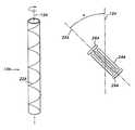
- FIG. 1is an elevational view of an ePTFE tube
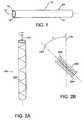
- FIG. 2Ais an elevational view of a helically wound tube twisted in a first rotational direction
- FIG. 2Bis a schematic of the node and fibril orientation of the first tube in a helically wound state
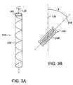
- FIG. 3Ais an elevational view of a helically wound tube twisted in a second rotational direction
- FIG. 3Bis a schematic of the node and fibril orientation of the second tube in a helically wound state
- FIG. 4Ais an elevational view of a prosthesis formed in accordance with the subject invention.
- FIG. 4Bis a schematic of the node and fibril orientations of the composite prosthesis.
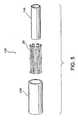
- FIG. 5is an exploded view of a prosthesis having a radially-expandable support member.
- the invention hereinprovides a multi-layer prosthesis which may be used as a graft to replace a portion of a bodily passageway (e.g., vascular graft), or within a bodily passageway to maintain patency thereof, such as an endovascular stent-graft.
- a bodily passagewaye.g., vascular graft
- the prosthesiscan be used in other bodily applications, such as the esophagus, trachea, colon, biliary tract, urinary tract, prostate, and the brain.
- the prosthesisis composed of multiple layers, including coaxially disposed ePTFE tubes.
- an ePTFE tube 10is shown which extends along a longitudinal axis 12 .
- the ePTFE tube 10is preferably formed by extrusion, thus having its fibrils generally parallel to the extrusion direction of the tube, which coincides with the longitudinal axis 12 .
- the ePTFE tube 10includes a wall 14 (which is seamless if extruded), that extends about a lumen 16 .
- the wall 14includes an inner luminal surface 18 facing the lumen 16 , and an outer, abluminal surface 20 .
- the ePTFE tubemay be formed of any length and of various dimensions, although it is preferred that the dimensions be generally constant throughout the length thereof.
- first and second tubes of the inventionlike reference numerals will be used to describe like elements, but with the extensions “A” and “B” for differentiation. Elements associated with a first tube will have the extension “A”, while elements associated with a second tube will have the extension “B”.
- a first ePTFE tube 10 Ais shown disposed along a longitudinal axis 12 A.
- the first tube 10 Ais twisted about its longitudinal axis 12 A in a first rotational direction, such as clockwise, as shown in FIG. 2 A.
- the tube 10 Amay be twisted over any given range of degrees, although it is preferred that the tube be twisted at least 10 degrees.
- the first tube 10 Ais helically wound in the first rotational direction.
- fibrils 24 Aare generally parallel to the reference axis 22 A, with the fibrils 24 A being angularly offset an angle ⁇ from the longitudinal axis 12 A, and, thus, being also angularly offset the angle ⁇ from the original extrusion direction of the first tube 10 A.
- Nodes 26 Aare generally perpendicular to the fibrils 24 A. With the fibrils 24 A, and the nodes 26 A, being obliquely disposed relative to the longitudinal axis 12 A, failure along the longitudinal axis 12 A may be reduced.
- a second ePTFE tube 10 Bis shown being twisted in a second rotational direction different than the first rotational direction of the first tube 10 A.
- the second ePTFE tubeis twisted in a counterclockwise direction.
- the particular rotational direction of twistingmay be switched for the first and second tubes 10 A and 10 B.
- the amount of twisting of the second tube 10 Bmay be varied, although it is preferred that at least a 10 degree displacement be provided.
- the helically wound distortion of the second tube 10 Bis represented by the hypothetical reference axis 22 B. As shown in FIG.
- fibrils 24 Bare generally parallel to the reference axis 22 B and are angularly offset an angle ⁇ from the longitudinal axis 12 B (and, thus, the extrusion direction).
- Nodes 26 Bare generally perpendicular to the fibrils 26 A. The oblique disposition of the fibrils 24 B and the nodes 26 B resists failure along the longitudinal axis 12 B.
- FIG. 4Ashows a prosthesis 100 including the first tube 10 A, in its twisted helical state being coaxially disposed within, and fixed to, the second tube 10 B, in its twisted helical state. It is preferred that the tubes 10 A and 10 B be generally coextensive, although the ends of the tubes need not be coterminous. Because of the different rotational orientations of the node and fibril structures of the tubes 10 A and 10 B, the node and fibril structures are angularly offset from each other. In particular, as shown schematically in FIG. 4B, because of the coaxial arrangement of the tubes 10 A, 10 B, the longitudinal axes 12 A and 12 B are generally colinear.
- the fibrils 24 A of the first tube 10 Aare angularly offset from the fibrils 24 B of the second tube 10 B by an angle ⁇ .
- the angular offset of the fibrils 24 A and 24 Bprovides the prosthesis 100 with resistance against failure not provided by either tube 10 A, 10 B alone.
- the angles ⁇ and ⁇being each at least 10 degrees
- the angle ⁇will be at least 20 degrees.
- the node and fibrils of each of the tubes 10 A, 10 Bare generally-equally angularly offset throughout the respective tube 10 A, 10 B.
- the second tube 10 Bis formed dimensionally slightly larger to accommodate the first tube 10 A within its lumen 16 B.
- only one of the tubes 10 A, 10 Bmay be twisted.
- the node and fibrils of the two tubes 10 A, 10 Bwould, nevertheless, be angularly offset.
- the first tube 10 Ais provided and mounted onto a mandrel where it is twisted into its desired helical configuration.
- the twisted configuration of the first tube 10 Ais maintained.
- the second tube 10 Bis provided and twisted as desired, and in its twisted state telescoped over the first tube 10 A.
- the first and second tubes 10 A and 10 Bare fixed together using any technique known to those skilled in the art, preferably sintering. Adhesive may also be used to bond the tubes, such as a thermoplastic fluoropolymer adhesive (e.g., FEP).
- FEPthermoplastic fluoropolymer adhesive
- tubes formed by other techniquesmay also be used, such as with rolling a sheet, or wrapping a tape.
- the fibrils of the ePTFEwill not initially be oriented parallel to the longitudinal axis of the tube, but rather transverse thereto.
- These non-extruded tubesmay replace one or more of the tubes 10 A, 10 B in a non-twisted state or in a twisted state.
- the prosthesis 100may also include a radially expandable support member 28 , which may be disposed interiorly of the first tube 10 A, exteriorly of the second tube 10 B, or interposed between the two tubes 10 A, 10 B. Additionally, multiple support members located at the aforementioned locations may be provided.
- the radially expandable support member 28may be fixed to the tubes 10 A, 10 B using any technique known to those skilled in the art, such as bonding. Additionally, with the radially expandable support member 28 being interposed between the tubes 10 A, 10 B, the tubes 10 A, 10 B may be fixed together through any interstices formed in the radially expandable support member 28 .
- the radially expandable support member 28may be of any construction known in the prior art which can maintain patency of the prosthesis 100 .
- the radially-expandable support member 28may be a stent.
- the particular stent 28 shown in FIG. 5is fully described in commonly assigned U.S. Pat. No. 5,693,085 to Buirge et al., and the disclosure of U.S. Pat. No. 5,693,085 is incorporated by reference herein.
- the stentmay be an intraluminally implantable stent formed of a metal such as stainless steel or tantalum, a temperature-sensitive material such as Nitinol, or alternatively formed of a superelastic alloy or suitable polymer.
- various stent types and stent constructionsmay be employed for the use anticipated herein.
- various useful radially-expandable support members 28include, without limitation, self-expanding stints and balloon expandable stints.
- the stintsmay be capable of radially contracting as well.
- Self-expanding stintsinclude those that have a spring-like action which causes the stent to radially expand or stints which expand due to the memory properties of the stent material for a particular configuration at a certain temperature.
- Other materialsare of course contemplated, such as stainless steel, platinum, gold, titanium, tantalum, niobium, and other biocompatible materials, as well as polymeric stints.
- the configuration of the radially-expandable support member 28may also be chosen from a host of geometries.
- wire stintscan be fastened in a continuous helical pattern, with or without wave-like forms or zig-zags in the wire, to form a radially deformable stent.
- Individual rings or circular memberscan be linked together such as by struts, sutures, or interlacing or locking of the rings to form a tubular stent.
- the prosthesis 100may be used with additional layers which may be formed of polymeric material and/or fabric. Furthermore, any layer or portion of the prosthesis 100 , including the tubes 10 A, 10 B, may be impregnated with one or more therapeutic and pharmacological substances prior to implantation of the prosthesis 100 for controlled release over an extended duration. It is anticipated that the prosthesis 100 can be partially or wholly coated with hydrophilic or drug delivery-type coatings which facilitate long-term healing of diseased vessels.
- Such a coatingis preferably bioabsorbable, and is preferably a therapeutic agent or drug, including, but not limited to, anti-thrombogenic agents (such as heparin, heparin derivatives, urokinase, and PPack (dextrophenylalanine proline arginine chloromethylketone); anti-proliferative agents (such as enoxaprin, angiopeptin, or monoclonal antibodies capable of blocking smooth muscle cell proliferation, hirudin, and acetylsalicylic acid); anti-inflammatory agents (such as dexamethasone, prednisolone, corticosterone, budesonide, estrogen, sulfasalazine, and mesalamine); antineoplastic/antiproliferative/anti-miotic agents (such as paclitaxel, 5-fluorouracil, cisplatin, vinblastine, vincristine, epothilones, endostatin, angiostatin
Landscapes
- Health & Medical Sciences (AREA)
- Gastroenterology & Hepatology (AREA)
- Pulmonology (AREA)
- Cardiology (AREA)
- Oral & Maxillofacial Surgery (AREA)
- Transplantation (AREA)
- Engineering & Computer Science (AREA)
- Biomedical Technology (AREA)
- Heart & Thoracic Surgery (AREA)
- Vascular Medicine (AREA)
- Life Sciences & Earth Sciences (AREA)
- Animal Behavior & Ethology (AREA)
- General Health & Medical Sciences (AREA)
- Public Health (AREA)
- Veterinary Medicine (AREA)
- Prostheses (AREA)
- Materials For Medical Uses (AREA)
Abstract
Description
Claims (7)
Priority Applications (7)
| Application Number | Priority Date | Filing Date | Title |
|---|---|---|---|
| US09/990,422US6719784B2 (en) | 2001-11-21 | 2001-11-21 | Counter rotational layering of ePTFE to improve mechanical properties of a prosthesis |
| EP02773395AEP1446072A1 (en) | 2001-11-21 | 2002-09-16 | COUNTER ROTATIONAL LAYERING OF ePTFE TO IMPROVE MECHANICAL PROPERTIES OF A PROSTHESIS |
| JP2003546787AJP4256262B2 (en) | 2001-11-21 | 2002-09-16 | Reverse rotation stratification of ePTFE to improve the mechanical properties of the prosthesis |
| PCT/US2002/029291WO2003045281A1 (en) | 2001-11-21 | 2002-09-16 | COUNTER ROTATIONAL LAYERING OF ePTFE TO IMPROVE MECHANICAL PROPERTIES OF A PROSTHESIS |
| AU2002336540AAU2002336540A1 (en) | 2001-11-21 | 2002-09-16 | COUNTER ROTATIONAL LAYERING OF ePTFE TO IMPROVE MECHANICAL PROPERTIES OF A PROSTHESIS |
| US10/775,442US7056412B2 (en) | 2001-11-21 | 2004-02-10 | Counter rotational layering of ePTFE to improve mechanical properties of a prosthesis |
| US11/410,116US7682386B2 (en) | 2001-11-21 | 2006-04-24 | Counter rotational layering of ePTFE to improve mechanical properties of a prosthesis |
Applications Claiming Priority (1)
| Application Number | Priority Date | Filing Date | Title |
|---|---|---|---|
| US09/990,422US6719784B2 (en) | 2001-11-21 | 2001-11-21 | Counter rotational layering of ePTFE to improve mechanical properties of a prosthesis |
Related Child Applications (1)
| Application Number | Title | Priority Date | Filing Date |
|---|---|---|---|
| US10/775,442DivisionUS7056412B2 (en) | 2001-11-21 | 2004-02-10 | Counter rotational layering of ePTFE to improve mechanical properties of a prosthesis |
Publications (2)
| Publication Number | Publication Date |
|---|---|
| US20030097174A1 US20030097174A1 (en) | 2003-05-22 |
| US6719784B2true US6719784B2 (en) | 2004-04-13 |
Family
ID=25536132
Family Applications (3)
| Application Number | Title | Priority Date | Filing Date |
|---|---|---|---|
| US09/990,422Expired - LifetimeUS6719784B2 (en) | 2001-11-21 | 2001-11-21 | Counter rotational layering of ePTFE to improve mechanical properties of a prosthesis |
| US10/775,442Expired - Fee RelatedUS7056412B2 (en) | 2001-11-21 | 2004-02-10 | Counter rotational layering of ePTFE to improve mechanical properties of a prosthesis |
| US11/410,116Expired - Fee RelatedUS7682386B2 (en) | 2001-11-21 | 2006-04-24 | Counter rotational layering of ePTFE to improve mechanical properties of a prosthesis |
Family Applications After (2)
| Application Number | Title | Priority Date | Filing Date |
|---|---|---|---|
| US10/775,442Expired - Fee RelatedUS7056412B2 (en) | 2001-11-21 | 2004-02-10 | Counter rotational layering of ePTFE to improve mechanical properties of a prosthesis |
| US11/410,116Expired - Fee RelatedUS7682386B2 (en) | 2001-11-21 | 2006-04-24 | Counter rotational layering of ePTFE to improve mechanical properties of a prosthesis |
Country Status (5)
| Country | Link |
|---|---|
| US (3) | US6719784B2 (en) |
| EP (1) | EP1446072A1 (en) |
| JP (1) | JP4256262B2 (en) |
| AU (1) | AU2002336540A1 (en) |
| WO (1) | WO2003045281A1 (en) |
Cited By (32)
| Publication number | Priority date | Publication date | Assignee | Title |
|---|---|---|---|---|
| US20030191479A1 (en)* | 2002-04-03 | 2003-10-09 | Thornton Sally C. | Body lumen closure |
| US20040034403A1 (en)* | 2002-04-27 | 2004-02-19 | Klaus Schmitt | Self-expanding stent |
| US20040049264A1 (en)* | 2002-09-06 | 2004-03-11 | Scimed Life Systems, Inc. | ePTFE crimped graft |
| US20040059411A1 (en)* | 2000-10-26 | 2004-03-25 | Strecker Ernst Peter | Implantable valve system |
| US20040127848A1 (en)* | 2002-12-30 | 2004-07-01 | Toby Freyman | Valve treatment catheter and methods |
| US20040230297A1 (en)* | 2002-04-03 | 2004-11-18 | Boston Scientific Corporation | Artificial valve |
| US20060047338A1 (en)* | 2004-09-02 | 2006-03-02 | Scimed Life Systems, Inc. | Cardiac valve, system, and method |
| US20060195174A1 (en)* | 2001-11-21 | 2006-08-31 | Scimed Life Systems, Inc. | Counter rotational layering of ePTFE to improve mechanical properties of a prosthesis |
| US7267686B2 (en) | 1999-10-21 | 2007-09-11 | Boston Scientific Scimed, Inc | Implantable prosthetic valve |
| US7416557B2 (en) | 2002-10-24 | 2008-08-26 | Boston Scientific Scimed, Inc. | Venous valve apparatus and method |
| US20090048658A1 (en)* | 2007-08-15 | 2009-02-19 | Boston Scientific Scimed, Inc. | Skewed nodal-fibril ePTFE structure |
| US7569071B2 (en) | 2005-09-21 | 2009-08-04 | Boston Scientific Scimed, Inc. | Venous valve, system, and method with sinus pocket |
| US7670368B2 (en) | 2005-02-07 | 2010-03-02 | Boston Scientific Scimed, Inc. | Venous valve apparatus, system, and method |
| US7722666B2 (en) | 2005-04-15 | 2010-05-25 | Boston Scientific Scimed, Inc. | Valve apparatus, system and method |
| US7780722B2 (en) | 2005-02-07 | 2010-08-24 | Boston Scientific Scimed, Inc. | Venous valve apparatus, system, and method |
| US7799038B2 (en) | 2006-01-20 | 2010-09-21 | Boston Scientific Scimed, Inc. | Translumenal apparatus, system, and method |
| US7854761B2 (en) | 2003-12-19 | 2010-12-21 | Boston Scientific Scimed, Inc. | Methods for venous valve replacement with a catheter |
| US7854755B2 (en) | 2005-02-01 | 2010-12-21 | Boston Scientific Scimed, Inc. | Vascular catheter, system, and method |
| US7867274B2 (en) | 2005-02-23 | 2011-01-11 | Boston Scientific Scimed, Inc. | Valve apparatus, system and method |
| US7878966B2 (en) | 2005-02-04 | 2011-02-01 | Boston Scientific Scimed, Inc. | Ventricular assist and support device |
| US7892276B2 (en) | 2007-12-21 | 2011-02-22 | Boston Scientific Scimed, Inc. | Valve with delayed leaflet deployment |
| US7967853B2 (en) | 2007-02-05 | 2011-06-28 | Boston Scientific Scimed, Inc. | Percutaneous valve, system and method |
| US8012198B2 (en) | 2005-06-10 | 2011-09-06 | Boston Scientific Scimed, Inc. | Venous valve, system, and method |
| US8088060B2 (en) | 2000-03-15 | 2012-01-03 | Orbusneich Medical, Inc. | Progenitor endothelial cell capturing with a drug eluting implantable medical device |
| US8128681B2 (en) | 2003-12-19 | 2012-03-06 | Boston Scientific Scimed, Inc. | Venous valve apparatus, system, and method |
| US8133270B2 (en) | 2007-01-08 | 2012-03-13 | California Institute Of Technology | In-situ formation of a valve |
| US8828079B2 (en) | 2007-07-26 | 2014-09-09 | Boston Scientific Scimed, Inc. | Circulatory valve, system and method |
| US9522217B2 (en) | 2000-03-15 | 2016-12-20 | Orbusneich Medical, Inc. | Medical device with coating for capturing genetically-altered cells and methods for using same |
| US9622859B2 (en) | 2005-02-01 | 2017-04-18 | Boston Scientific Scimed, Inc. | Filter system and method |
| US9668859B2 (en) | 2011-08-05 | 2017-06-06 | California Institute Of Technology | Percutaneous heart valve delivery systems |
| US9744037B2 (en) | 2013-03-15 | 2017-08-29 | California Institute Of Technology | Handle mechanism and functionality for repositioning and retrieval of transcatheter heart valves |
| US20190060593A1 (en)* | 2015-10-24 | 2019-02-28 | Smiths Medical International Limited | Medico-surgical tubes and their manufacture |
Families Citing this family (26)
| Publication number | Priority date | Publication date | Assignee | Title |
|---|---|---|---|---|
| US5961545A (en)* | 1997-01-17 | 1999-10-05 | Meadox Medicals, Inc. | EPTFE graft-stent composite device |
| US6395019B2 (en) | 1998-02-09 | 2002-05-28 | Trivascular, Inc. | Endovascular graft |
| JP4331610B2 (en) | 2001-12-20 | 2009-09-16 | トリバスキュラー2,インコーポレイティド | Advanced endovascular graft |
| US7147661B2 (en) | 2001-12-20 | 2006-12-12 | Boston Scientific Santa Rosa Corp. | Radially expandable stent |
| US7090693B1 (en) | 2001-12-20 | 2006-08-15 | Boston Scientific Santa Rosa Corp. | Endovascular graft joint and method for manufacture |
| US7125464B2 (en)* | 2001-12-20 | 2006-10-24 | Boston Scientific Santa Rosa Corp. | Method for manufacturing an endovascular graft section |
| US6776604B1 (en) | 2001-12-20 | 2004-08-17 | Trivascular, Inc. | Method and apparatus for shape forming endovascular graft material |
| US7803178B2 (en) | 2004-01-30 | 2010-09-28 | Trivascular, Inc. | Inflatable porous implants and methods for drug delivery |
| US8034096B2 (en) | 2004-03-31 | 2011-10-11 | Cook Medical Technologies Llc | Stent-graft with graft to graft attachment |
| US20050223440A1 (en)* | 2004-03-31 | 2005-10-06 | Council Of Scientific And Industrial Research | Tissue culture process for producing cotton plants |
| US7794490B2 (en)* | 2004-06-22 | 2010-09-14 | Boston Scientific Scimed, Inc. | Implantable medical devices with antimicrobial and biodegradable matrices |
| US20060020328A1 (en)* | 2004-07-23 | 2006-01-26 | Tan Sharon M L | Composite vascular graft having bioactive agent |
| WO2006065665A1 (en)* | 2004-12-13 | 2006-06-22 | Robert Hunt Carpenter, Dvm, Pc | Multi-wall expandable device capable of drug delivery |
| WO2006080008A2 (en)* | 2005-01-25 | 2006-08-03 | Nicast Ltd. | Artificial vascular prosthesis |
| US20060233990A1 (en) | 2005-04-13 | 2006-10-19 | Trivascular, Inc. | PTFE layers and methods of manufacturing |
| US20060233991A1 (en) | 2005-04-13 | 2006-10-19 | Trivascular, Inc. | PTFE layers and methods of manufacturing |
| US8226701B2 (en) | 2007-09-26 | 2012-07-24 | Trivascular, Inc. | Stent and delivery system for deployment thereof |
| US8066755B2 (en) | 2007-09-26 | 2011-11-29 | Trivascular, Inc. | System and method of pivoted stent deployment |
| US8663309B2 (en) | 2007-09-26 | 2014-03-04 | Trivascular, Inc. | Asymmetric stent apparatus and method |
| US10159557B2 (en) | 2007-10-04 | 2018-12-25 | Trivascular, Inc. | Modular vascular graft for low profile percutaneous delivery |
| US8083789B2 (en) | 2007-11-16 | 2011-12-27 | Trivascular, Inc. | Securement assembly and method for expandable endovascular device |
| US8328861B2 (en) | 2007-11-16 | 2012-12-11 | Trivascular, Inc. | Delivery system and method for bifurcated graft |
| KR101626234B1 (en)* | 2012-01-16 | 2016-05-31 | 더블유.엘. 고어 앤드 어소시에이트스, 인코포레이티드 | Articles including expanded polytetrafluoroethylene membranes with serpentine fibrils and having a discontinuous fluoropolymer layer thereon |
| US8992595B2 (en) | 2012-04-04 | 2015-03-31 | Trivascular, Inc. | Durable stent graft with tapered struts and stable delivery methods and devices |
| US9498363B2 (en) | 2012-04-06 | 2016-11-22 | Trivascular, Inc. | Delivery catheter for endovascular device |
| CN106551731A (en)* | 2014-01-29 | 2017-04-05 | 华瑞(福建)生物科技有限公司 | A kind of degradable screw type artificial trachea and preparation method thereof |
Citations (16)
| Publication number | Priority date | Publication date | Assignee | Title |
|---|---|---|---|---|
| US2945265A (en) | 1957-02-25 | 1960-07-19 | Revere Corp America | Method for making insulated wire |
| US3008187A (en) | 1959-01-05 | 1961-11-14 | Raybestos Manhattan Inc | Method and apparatus for extruding polytetrafluoroethylene tubing |
| US3260774A (en) | 1963-01-21 | 1966-07-12 | Tensolite Insulated Wire Co In | Method for the continuous extrusion of unsintered polytetrafluoroethylene powder |
| US4104394A (en) | 1975-12-15 | 1978-08-01 | Sumitomo Electric Industries, Ltd. | Method for diametrically expanding thermally contractive ptfe resin tube |
| US4225547A (en) | 1975-12-15 | 1980-09-30 | Sumitomo Electric Industries, Ltd. | Extrusion process of polytetrafluoroethylene tubing materials and apparatus therefor |
| US4743480A (en) | 1986-11-13 | 1988-05-10 | W. L. Gore & Associates, Inc. | Apparatus and method for extruding and expanding polytetrafluoroethylene tubing and the products produced thereby |
| US4876051A (en) | 1986-11-13 | 1989-10-24 | W. L. Gore & Associates, Inc. | Apparatus and method for extruding and expanding polytetrafluoroethylene tubing and the products produced thereby |
| US5156785A (en) | 1991-07-10 | 1992-10-20 | Cordis Corporation | Extruded tubing and catheters having increased rotational stiffness |
| US5505887A (en) | 1994-03-10 | 1996-04-09 | Meadox Medicals, Inc. | Extrusion process for manufacturing PTFE products |
| WO1997002791A1 (en) | 1995-07-07 | 1997-01-30 | W.L. Gore & Associates, Inc. | Interior liner for tubes, pipes and blood conduits |
| EP0775472A2 (en) | 1995-11-21 | 1997-05-28 | Schneider (Usa) Inc. | Expandable stent graft covered with expanded polytetrafluoroethylene |
| US5800512A (en) | 1996-01-22 | 1998-09-01 | Meadox Medicals, Inc. | PTFE vascular graft |
| US5824046A (en) | 1996-09-27 | 1998-10-20 | Scimed Life Systems, Inc. | Covered stent |
| US5928279A (en)* | 1996-07-03 | 1999-07-27 | Baxter International Inc. | Stented, radially expandable, tubular PTFE grafts |
| US6027779A (en) | 1993-08-18 | 2000-02-22 | W. L. Gore & Associates, Inc. | Thin-wall polytetrafluoroethylene tube |
| WO2000043052A1 (en) | 1999-01-22 | 2000-07-27 | Gore Entreprise Holdings, Inc. | Vascular graft with improved surface flow |
Family Cites Families (16)
| Publication number | Priority date | Publication date | Assignee | Title |
|---|---|---|---|---|
| US2667852A (en)* | 1947-05-01 | 1954-02-02 | Brown Fintube Co | Apparatus for twisting helical fins and bonding them to tubes |
| CH409168A (en)* | 1963-07-11 | 1966-03-15 | Heraeus Schott Quarzschmelze | Infrared heater |
| US3730229A (en)* | 1971-03-11 | 1973-05-01 | Turbotec Inc | Tubing unit with helically corrugated tube and method for making same |
| US3893878A (en)* | 1971-07-12 | 1975-07-08 | Kaempen Industries | Method for making a composite structure |
| US4550447A (en)* | 1983-08-03 | 1985-11-05 | Shiley Incorporated | Vascular graft prosthesis |
| GB2204945B (en)* | 1987-05-22 | 1991-04-24 | Nuovo Pignone Spa | Heat exchanger for the domestic heating of water |
| US5282847A (en)* | 1991-02-28 | 1994-02-01 | Medtronic, Inc. | Prosthetic vascular grafts with a pleated structure |
| US5450860A (en)* | 1993-08-31 | 1995-09-19 | W. L. Gore & Associates, Inc. | Device for tissue repair and method for employing same |
| US5609624A (en)* | 1993-10-08 | 1997-03-11 | Impra, Inc. | Reinforced vascular graft and method of making same |
| US5393260A (en)* | 1993-12-10 | 1995-02-28 | Eljer Manufacturing, Inc. | Flexible double wall vent pipe |
| US5891108A (en)* | 1994-09-12 | 1999-04-06 | Cordis Corporation | Drug delivery stent |
| US6451047B2 (en)* | 1995-03-10 | 2002-09-17 | Impra, Inc. | Encapsulated intraluminal stent-graft and methods of making same |
| US6042605A (en)* | 1995-12-14 | 2000-03-28 | Gore Enterprose Holdings, Inc. | Kink resistant stent-graft |
| US6403887B1 (en)* | 1997-12-16 | 2002-06-11 | Tensolite Company | High speed data transmission cable and method of forming same |
| US20020049489A1 (en)* | 2000-07-11 | 2002-04-25 | Herweck Steve A. | Prosthesis and method of making a prosthesis having an external support structure |
| US6719784B2 (en)* | 2001-11-21 | 2004-04-13 | Scimed Life Systems, Inc. | Counter rotational layering of ePTFE to improve mechanical properties of a prosthesis |
- 2001
- 2001-11-21USUS09/990,422patent/US6719784B2/ennot_activeExpired - Lifetime
- 2002
- 2002-09-16JPJP2003546787Apatent/JP4256262B2/ennot_activeExpired - Fee Related
- 2002-09-16WOPCT/US2002/029291patent/WO2003045281A1/enactiveApplication Filing
- 2002-09-16AUAU2002336540Apatent/AU2002336540A1/ennot_activeAbandoned
- 2002-09-16EPEP02773395Apatent/EP1446072A1/ennot_activeWithdrawn
- 2004
- 2004-02-10USUS10/775,442patent/US7056412B2/ennot_activeExpired - Fee Related
- 2006
- 2006-04-24USUS11/410,116patent/US7682386B2/ennot_activeExpired - Fee Related
Patent Citations (18)
| Publication number | Priority date | Publication date | Assignee | Title |
|---|---|---|---|---|
| US2945265A (en) | 1957-02-25 | 1960-07-19 | Revere Corp America | Method for making insulated wire |
| US3008187A (en) | 1959-01-05 | 1961-11-14 | Raybestos Manhattan Inc | Method and apparatus for extruding polytetrafluoroethylene tubing |
| US3260774A (en) | 1963-01-21 | 1966-07-12 | Tensolite Insulated Wire Co In | Method for the continuous extrusion of unsintered polytetrafluoroethylene powder |
| US4104394A (en) | 1975-12-15 | 1978-08-01 | Sumitomo Electric Industries, Ltd. | Method for diametrically expanding thermally contractive ptfe resin tube |
| US4225547A (en) | 1975-12-15 | 1980-09-30 | Sumitomo Electric Industries, Ltd. | Extrusion process of polytetrafluoroethylene tubing materials and apparatus therefor |
| US4743480A (en) | 1986-11-13 | 1988-05-10 | W. L. Gore & Associates, Inc. | Apparatus and method for extruding and expanding polytetrafluoroethylene tubing and the products produced thereby |
| US4876051A (en) | 1986-11-13 | 1989-10-24 | W. L. Gore & Associates, Inc. | Apparatus and method for extruding and expanding polytetrafluoroethylene tubing and the products produced thereby |
| US5156785A (en) | 1991-07-10 | 1992-10-20 | Cordis Corporation | Extruded tubing and catheters having increased rotational stiffness |
| US6027779A (en) | 1993-08-18 | 2000-02-22 | W. L. Gore & Associates, Inc. | Thin-wall polytetrafluoroethylene tube |
| US5505887A (en) | 1994-03-10 | 1996-04-09 | Meadox Medicals, Inc. | Extrusion process for manufacturing PTFE products |
| US5874032A (en) | 1994-03-10 | 1999-02-23 | Meadox Medicals, Inc. | Method for manufacturing expanded polytetrafluoroethylene products |
| WO1997002791A1 (en) | 1995-07-07 | 1997-01-30 | W.L. Gore & Associates, Inc. | Interior liner for tubes, pipes and blood conduits |
| EP0775472A2 (en) | 1995-11-21 | 1997-05-28 | Schneider (Usa) Inc. | Expandable stent graft covered with expanded polytetrafluoroethylene |
| US5788626A (en)* | 1995-11-21 | 1998-08-04 | Schneider (Usa) Inc | Method of making a stent-graft covered with expanded polytetrafluoroethylene |
| US5800512A (en) | 1996-01-22 | 1998-09-01 | Meadox Medicals, Inc. | PTFE vascular graft |
| US5928279A (en)* | 1996-07-03 | 1999-07-27 | Baxter International Inc. | Stented, radially expandable, tubular PTFE grafts |
| US5824046A (en) | 1996-09-27 | 1998-10-20 | Scimed Life Systems, Inc. | Covered stent |
| WO2000043052A1 (en) | 1999-01-22 | 2000-07-27 | Gore Entreprise Holdings, Inc. | Vascular graft with improved surface flow |
Non-Patent Citations (1)
| Title |
|---|
| Copy of Search Report issued on Dec. 16, 2002 for International Application No. PCT/US 02/29291. |
Cited By (71)
| Publication number | Priority date | Publication date | Assignee | Title |
|---|---|---|---|---|
| US7267686B2 (en) | 1999-10-21 | 2007-09-11 | Boston Scientific Scimed, Inc | Implantable prosthetic valve |
| US8088060B2 (en) | 2000-03-15 | 2012-01-03 | Orbusneich Medical, Inc. | Progenitor endothelial cell capturing with a drug eluting implantable medical device |
| US9522217B2 (en) | 2000-03-15 | 2016-12-20 | Orbusneich Medical, Inc. | Medical device with coating for capturing genetically-altered cells and methods for using same |
| US7156872B2 (en) | 2000-10-26 | 2007-01-02 | Ernst Peter Strecker | Implantable valve system |
| US20040059411A1 (en)* | 2000-10-26 | 2004-03-25 | Strecker Ernst Peter | Implantable valve system |
| US7776053B2 (en) | 2000-10-26 | 2010-08-17 | Boston Scientific Scimed, Inc. | Implantable valve system |
| US7682386B2 (en)* | 2001-11-21 | 2010-03-23 | Boston Scientific Scimed, Inc. | Counter rotational layering of ePTFE to improve mechanical properties of a prosthesis |
| US20060195174A1 (en)* | 2001-11-21 | 2006-08-31 | Scimed Life Systems, Inc. | Counter rotational layering of ePTFE to improve mechanical properties of a prosthesis |
| US20040230297A1 (en)* | 2002-04-03 | 2004-11-18 | Boston Scientific Corporation | Artificial valve |
| US7682385B2 (en) | 2002-04-03 | 2010-03-23 | Boston Scientific Corporation | Artificial valve |
| US7007698B2 (en) | 2002-04-03 | 2006-03-07 | Boston Scientific Corporation | Body lumen closure |
| US20030191479A1 (en)* | 2002-04-03 | 2003-10-09 | Thornton Sally C. | Body lumen closure |
| US7081131B2 (en) | 2002-04-03 | 2006-07-25 | Boston Scientific Corporation | Artificial valve |
| US20060142832A1 (en)* | 2002-04-27 | 2006-06-29 | Klaus Schmitt | Self-expanding stent |
| US7387641B2 (en)* | 2002-04-27 | 2008-06-17 | Boston Scientific Scimed, Inc. | Self-expanding stent |
| US7458986B2 (en)* | 2002-04-27 | 2008-12-02 | Boston Scientific Scimed, Inc. | Self-expanding stent |
| US20040034403A1 (en)* | 2002-04-27 | 2004-02-19 | Klaus Schmitt | Self-expanding stent |
| US20040049264A1 (en)* | 2002-09-06 | 2004-03-11 | Scimed Life Systems, Inc. | ePTFE crimped graft |
| US7879085B2 (en) | 2002-09-06 | 2011-02-01 | Boston Scientific Scimed, Inc. | ePTFE crimped graft |
| US7416557B2 (en) | 2002-10-24 | 2008-08-26 | Boston Scientific Scimed, Inc. | Venous valve apparatus and method |
| US7244242B2 (en) | 2002-12-30 | 2007-07-17 | Boston Scientific Scimed, Inc. | Valve treatment catheter and methods |
| US7780627B2 (en) | 2002-12-30 | 2010-08-24 | Boston Scientific Scimed, Inc. | Valve treatment catheter and methods |
| US20040127848A1 (en)* | 2002-12-30 | 2004-07-01 | Toby Freyman | Valve treatment catheter and methods |
| US6945957B2 (en) | 2002-12-30 | 2005-09-20 | Scimed Life Systems, Inc. | Valve treatment catheter and methods |
| US10869764B2 (en) | 2003-12-19 | 2020-12-22 | Boston Scientific Scimed, Inc. | Venous valve apparatus, system, and method |
| US8128681B2 (en) | 2003-12-19 | 2012-03-06 | Boston Scientific Scimed, Inc. | Venous valve apparatus, system, and method |
| US8721717B2 (en) | 2003-12-19 | 2014-05-13 | Boston Scientific Scimed, Inc. | Venous valve apparatus, system, and method |
| US9301843B2 (en) | 2003-12-19 | 2016-04-05 | Boston Scientific Scimed, Inc. | Venous valve apparatus, system, and method |
| US7854761B2 (en) | 2003-12-19 | 2010-12-21 | Boston Scientific Scimed, Inc. | Methods for venous valve replacement with a catheter |
| US8932349B2 (en) | 2004-09-02 | 2015-01-13 | Boston Scientific Scimed, Inc. | Cardiac valve, system, and method |
| US8002824B2 (en) | 2004-09-02 | 2011-08-23 | Boston Scientific Scimed, Inc. | Cardiac valve, system, and method |
| US20060047338A1 (en)* | 2004-09-02 | 2006-03-02 | Scimed Life Systems, Inc. | Cardiac valve, system, and method |
| US9918834B2 (en) | 2004-09-02 | 2018-03-20 | Boston Scientific Scimed, Inc. | Cardiac valve, system and method |
| US7566343B2 (en) | 2004-09-02 | 2009-07-28 | Boston Scientific Scimed, Inc. | Cardiac valve, system, and method |
| US7854755B2 (en) | 2005-02-01 | 2010-12-21 | Boston Scientific Scimed, Inc. | Vascular catheter, system, and method |
| US9622859B2 (en) | 2005-02-01 | 2017-04-18 | Boston Scientific Scimed, Inc. | Filter system and method |
| US7878966B2 (en) | 2005-02-04 | 2011-02-01 | Boston Scientific Scimed, Inc. | Ventricular assist and support device |
| US7670368B2 (en) | 2005-02-07 | 2010-03-02 | Boston Scientific Scimed, Inc. | Venous valve apparatus, system, and method |
| US7780722B2 (en) | 2005-02-07 | 2010-08-24 | Boston Scientific Scimed, Inc. | Venous valve apparatus, system, and method |
| US7867274B2 (en) | 2005-02-23 | 2011-01-11 | Boston Scientific Scimed, Inc. | Valve apparatus, system and method |
| US9808341B2 (en) | 2005-02-23 | 2017-11-07 | Boston Scientific Scimed Inc. | Valve apparatus, system and method |
| US9370419B2 (en) | 2005-02-23 | 2016-06-21 | Boston Scientific Scimed, Inc. | Valve apparatus, system and method |
| US8512399B2 (en) | 2005-04-15 | 2013-08-20 | Boston Scientific Scimed, Inc. | Valve apparatus, system and method |
| US7722666B2 (en) | 2005-04-15 | 2010-05-25 | Boston Scientific Scimed, Inc. | Valve apparatus, system and method |
| US9861473B2 (en) | 2005-04-15 | 2018-01-09 | Boston Scientific Scimed Inc. | Valve apparatus, system and method |
| US8012198B2 (en) | 2005-06-10 | 2011-09-06 | Boston Scientific Scimed, Inc. | Venous valve, system, and method |
| US11337812B2 (en) | 2005-06-10 | 2022-05-24 | Boston Scientific Scimed, Inc. | Venous valve, system and method |
| US9028542B2 (en) | 2005-06-10 | 2015-05-12 | Boston Scientific Scimed, Inc. | Venous valve, system, and method |
| US8460365B2 (en) | 2005-09-21 | 2013-06-11 | Boston Scientific Scimed, Inc. | Venous valve, system, and method with sinus pocket |
| US9474609B2 (en) | 2005-09-21 | 2016-10-25 | Boston Scientific Scimed, Inc. | Venous valve, system, and method with sinus pocket |
| US8672997B2 (en) | 2005-09-21 | 2014-03-18 | Boston Scientific Scimed, Inc. | Valve with sinus |
| US7569071B2 (en) | 2005-09-21 | 2009-08-04 | Boston Scientific Scimed, Inc. | Venous valve, system, and method with sinus pocket |
| US10548734B2 (en) | 2005-09-21 | 2020-02-04 | Boston Scientific Scimed, Inc. | Venous valve, system, and method with sinus pocket |
| US7951189B2 (en) | 2005-09-21 | 2011-05-31 | Boston Scientific Scimed, Inc. | Venous valve, system, and method with sinus pocket |
| US7799038B2 (en) | 2006-01-20 | 2010-09-21 | Boston Scientific Scimed, Inc. | Translumenal apparatus, system, and method |
| US8348999B2 (en) | 2007-01-08 | 2013-01-08 | California Institute Of Technology | In-situ formation of a valve |
| US8133270B2 (en) | 2007-01-08 | 2012-03-13 | California Institute Of Technology | In-situ formation of a valve |
| US7967853B2 (en) | 2007-02-05 | 2011-06-28 | Boston Scientific Scimed, Inc. | Percutaneous valve, system and method |
| US11504239B2 (en) | 2007-02-05 | 2022-11-22 | Boston Scientific Scimed, Inc. | Percutaneous valve, system and method |
| US9421083B2 (en) | 2007-02-05 | 2016-08-23 | Boston Scientific Scimed Inc. | Percutaneous valve, system and method |
| US8470023B2 (en) | 2007-02-05 | 2013-06-25 | Boston Scientific Scimed, Inc. | Percutaneous valve, system, and method |
| US10226344B2 (en) | 2007-02-05 | 2019-03-12 | Boston Scientific Scimed, Inc. | Percutaneous valve, system and method |
| US8828079B2 (en) | 2007-07-26 | 2014-09-09 | Boston Scientific Scimed, Inc. | Circulatory valve, system and method |
| US7785363B2 (en)* | 2007-08-15 | 2010-08-31 | Boston Scientific Scimed, Inc. | Skewed nodal-fibril ePTFE structure |
| US20090048658A1 (en)* | 2007-08-15 | 2009-02-19 | Boston Scientific Scimed, Inc. | Skewed nodal-fibril ePTFE structure |
| US8414641B2 (en) | 2007-12-21 | 2013-04-09 | Boston Scientific Scimed, Inc. | Valve with delayed leaflet deployment |
| US8137394B2 (en) | 2007-12-21 | 2012-03-20 | Boston Scientific Scimed, Inc. | Valve with delayed leaflet deployment |
| US7892276B2 (en) | 2007-12-21 | 2011-02-22 | Boston Scientific Scimed, Inc. | Valve with delayed leaflet deployment |
| US9668859B2 (en) | 2011-08-05 | 2017-06-06 | California Institute Of Technology | Percutaneous heart valve delivery systems |
| US9744037B2 (en) | 2013-03-15 | 2017-08-29 | California Institute Of Technology | Handle mechanism and functionality for repositioning and retrieval of transcatheter heart valves |
| US20190060593A1 (en)* | 2015-10-24 | 2019-02-28 | Smiths Medical International Limited | Medico-surgical tubes and their manufacture |
Also Published As
| Publication number | Publication date |
|---|---|
| US20060195174A1 (en) | 2006-08-31 |
| US7056412B2 (en) | 2006-06-06 |
| EP1446072A1 (en) | 2004-08-18 |
| WO2003045281A1 (en) | 2003-06-05 |
| JP2005533527A (en) | 2005-11-10 |
| AU2002336540A1 (en) | 2003-06-10 |
| US20040154721A1 (en) | 2004-08-12 |
| US20030097174A1 (en) | 2003-05-22 |
| US7682386B2 (en) | 2010-03-23 |
| JP4256262B2 (en) | 2009-04-22 |
Similar Documents
| Publication | Publication Date | Title |
|---|---|---|
| US6719784B2 (en) | Counter rotational layering of ePTFE to improve mechanical properties of a prosthesis | |
| CA2613351C (en) | Eptfe lamination-resizing eptfe tubing | |
| US8025693B2 (en) | Stent-graft having flexible geometries and methods of producing the same | |
| AU712190B2 (en) | Stented, radially expandable, tubular PTFE grafts | |
| US6001125A (en) | PTFE vascular prosthesis and method of manufacture | |
| US7354449B2 (en) | Covered stent and method of covering a stent | |
| EP1207815B1 (en) | Tubular stent-graft composite device and method of manufacture | |
| US6929709B2 (en) | Helically formed stent/graft assembly | |
| US20070208409A1 (en) | Flexible stent-graft devices and methods of producing the same | |
| JP4808927B2 (en) | Method for forming a prosthesis | |
| EP1063943B1 (en) | Improved ptfe vascular prosthesis and method of manufacture | |
| JP2003503151A (en) | Composite vascular graft | |
| US20090048657A1 (en) | Preferentially varying-density ePTFE structure | |
| WO2007041010A1 (en) | Variable lamination of vascular graft | |
| US8221486B2 (en) | Laminated stent graft edge binding | |
| US7785363B2 (en) | Skewed nodal-fibril ePTFE structure | |
| EP1767169B1 (en) | Tubular stent-graft composite device and method of manufacture |
Legal Events
| Date | Code | Title | Description |
|---|---|---|---|
| AS | Assignment | Owner name:SCIMED LIFE SYSTEMS, INC., MINNESOTA Free format text:ASSIGNMENT OF ASSIGNORS INTEREST;ASSIGNOR:HENDERSON, JAMIE S.;REEL/FRAME:012323/0944 Effective date:20011115 | |
| STCF | Information on status: patent grant | Free format text:PATENTED CASE | |
| AS | Assignment | Owner name:BOSTON SCIENTIFIC SCIMED, INC., MINNESOTA Free format text:CHANGE OF NAME;ASSIGNOR:SCIMED LIFE SYSTEMS, INC.;REEL/FRAME:018505/0868 Effective date:20050101 Owner name:BOSTON SCIENTIFIC SCIMED, INC.,MINNESOTA Free format text:CHANGE OF NAME;ASSIGNOR:SCIMED LIFE SYSTEMS, INC.;REEL/FRAME:018505/0868 Effective date:20050101 | |
| FPAY | Fee payment | Year of fee payment:4 | |
| FPAY | Fee payment | Year of fee payment:8 | |
| AS | Assignment | Owner name:ACACIA RESEARCH GROUP LLC, TEXAS Free format text:ASSIGNMENT OF ASSIGNORS INTEREST;ASSIGNOR:BOSTON SCIENTIFIC SCIMED, INC.;REEL/FRAME:030694/0461 Effective date:20121220 | |
| AS | Assignment | Owner name:LIFESHIELD SCIENCES LLC, TEXAS Free format text:ASSIGNMENT OF ASSIGNORS INTEREST;ASSIGNOR:ACACIA RESEARCH GROUP LLC;REEL/FRAME:030740/0225 Effective date:20130515 | |
| FPAY | Fee payment | Year of fee payment:12 |