US6719724B1 - Central venous line catheter having multiple heat exchange elements and multiple infusion lumens - Google Patents
Central venous line catheter having multiple heat exchange elements and multiple infusion lumensDownload PDFInfo
- Publication number
- US6719724B1 US6719724B1US09/816,645US81664501AUS6719724B1US 6719724 B1US6719724 B1US 6719724B1US 81664501 AUS81664501 AUS 81664501AUS 6719724 B1US6719724 B1US 6719724B1
- Authority
- US
- United States
- Prior art keywords
- catheter
- heat exchange
- infusion
- duct
- balloon
- Prior art date
- Legal status (The legal status is an assumption and is not a legal conclusion. Google has not performed a legal analysis and makes no representation as to the accuracy of the status listed.)
- Expired - Lifetime
Links
- 238000001802infusionMethods0.000titleclaimsabstractdescription172
- 239000012530fluidSubstances0.000claimsabstractdescription116
- 210000004204blood vesselAnatomy0.000claimsabstractdescription17
- 238000000034methodMethods0.000claimsabstractdescription16
- 238000004891communicationMethods0.000claimsdescription36
- 210000001124body fluidAnatomy0.000claimsdescription21
- 239000010839body fluidSubstances0.000claimsdescription21
- 238000012546transferMethods0.000claimsdescription21
- 238000010438heat treatmentMethods0.000claimsdescription10
- 210000003191femoral veinAnatomy0.000claimsdescription7
- 239000012510hollow fiberSubstances0.000claimsdescription4
- 238000003780insertionMethods0.000claimsdescription4
- 230000037431insertionEffects0.000claimsdescription4
- 230000000694effectsEffects0.000claimsdescription2
- 239000011248coating agentSubstances0.000claims4
- 238000000576coating methodMethods0.000claims4
- 239000003146anticoagulant agentSubstances0.000claims1
- 229940127219anticoagulant drugDrugs0.000claims1
- 239000012809cooling fluidSubstances0.000claims1
- 239000008280bloodSubstances0.000abstractdescription30
- 210000004369bloodAnatomy0.000abstractdescription30
- 238000001990intravenous administrationMethods0.000abstractdescription12
- 238000001816coolingMethods0.000description13
- 230000036770blood supplyEffects0.000description6
- 230000036760body temperatureEffects0.000description6
- 239000003814drugSubstances0.000description6
- 229940079593drugDrugs0.000description6
- 239000000463materialSubstances0.000description6
- 230000008901benefitEffects0.000description5
- 210000001631vena cava inferiorAnatomy0.000description5
- 230000002631hypothermal effectEffects0.000description4
- 239000011295pitchSubstances0.000description4
- RZVAJINKPMORJF-UHFFFAOYSA-NAcetaminophenChemical compoundCC(=O)NC1=CC=C(O)C=C1RZVAJINKPMORJF-UHFFFAOYSA-N0.000description3
- 208000006011StrokeDiseases0.000description3
- 210000004556brainAnatomy0.000description3
- -1chemotherapySubstances0.000description3
- 238000002483medicationMethods0.000description3
- 230000001766physiological effectEffects0.000description3
- 238000005070samplingMethods0.000description3
- CURLTUGMZLYLDI-UHFFFAOYSA-NCarbon dioxideChemical compoundO=C=OCURLTUGMZLYLDI-UHFFFAOYSA-N0.000description2
- 239000004677NylonSubstances0.000description2
- 206010037660PyrexiaDiseases0.000description2
- FAPWRFPIFSIZLT-UHFFFAOYSA-MSodium chlorideChemical compound[Na+].[Cl-]FAPWRFPIFSIZLT-UHFFFAOYSA-M0.000description2
- 208000007536ThrombosisDiseases0.000description2
- 230000004888barrier functionEffects0.000description2
- 230000000903blocking effectEffects0.000description2
- 230000017531blood circulationEffects0.000description2
- 238000005516engineering processMethods0.000description2
- 210000003111iliac veinAnatomy0.000description2
- 210000004731jugular veinAnatomy0.000description2
- 230000004060metabolic processEffects0.000description2
- 230000035764nutritionEffects0.000description2
- 235000016709nutritionNutrition0.000description2
- 229920001778nylonPolymers0.000description2
- 239000011780sodium chlorideSubstances0.000description2
- 210000001321subclavian veinAnatomy0.000description2
- 239000000126substanceSubstances0.000description2
- 238000002627tracheal intubationMethods0.000description2
- 210000005166vasculatureAnatomy0.000description2
- 210000002620vena cava superiorAnatomy0.000description2
- 238000010792warmingMethods0.000description2
- XLYOFNOQVPJJNP-UHFFFAOYSA-NwaterSubstancesOXLYOFNOQVPJJNP-UHFFFAOYSA-N0.000description2
- 102000004506Blood ProteinsHuman genes0.000description1
- 108010017384Blood ProteinsProteins0.000description1
- 206010048962Brain oedemaDiseases0.000description1
- OYPRJOBELJOOCE-UHFFFAOYSA-NCalciumChemical compound[Ca]OYPRJOBELJOOCE-UHFFFAOYSA-N0.000description1
- JOYRKODLDBILNP-UHFFFAOYSA-NEthyl urethaneChemical compoundCCOC(N)=OJOYRKODLDBILNP-UHFFFAOYSA-N0.000description1
- 208000010496Heart ArrestDiseases0.000description1
- HTTJABKRGRZYRN-UHFFFAOYSA-NHeparinChemical compoundOC1C(NC(=O)C)C(O)OC(COS(O)(=O)=O)C1OC1C(OS(O)(=O)=O)C(O)C(OC2C(C(OS(O)(=O)=O)C(OC3C(C(O)C(O)C(O3)C(O)=O)OS(O)(=O)=O)C(CO)O2)NS(O)(=O)=O)C(C(O)=O)O1HTTJABKRGRZYRN-UHFFFAOYSA-N0.000description1
- 229920002614Polyether block amidePolymers0.000description1
- 239000004698PolyethyleneSubstances0.000description1
- 229910000831SteelInorganic materials0.000description1
- 208000030886Traumatic Brain injuryDiseases0.000description1
- 230000004308accommodationEffects0.000description1
- 238000004458analytical methodMethods0.000description1
- 230000000845anti-microbial effectEffects0.000description1
- 239000004599antimicrobialSubstances0.000description1
- 238000013459approachMethods0.000description1
- 208000006752brain edemaDiseases0.000description1
- 229910052791calciumInorganic materials0.000description1
- 239000011575calciumSubstances0.000description1
- 229910002092carbon dioxideInorganic materials0.000description1
- 239000001569carbon dioxideSubstances0.000description1
- 230000008859changeEffects0.000description1
- 238000002512chemotherapyMethods0.000description1
- HGAZMNJKRQFZKS-UHFFFAOYSA-Nchloroethene;ethenyl acetateChemical compoundClC=C.CC(=O)OC=CHGAZMNJKRQFZKS-UHFFFAOYSA-N0.000description1
- 230000015271coagulationEffects0.000description1
- 238000005345coagulationMethods0.000description1
- 238000011443conventional therapyMethods0.000description1
- 230000006378damageEffects0.000description1
- 230000002939deleterious effectEffects0.000description1
- 238000013461designMethods0.000description1
- 230000001627detrimental effectEffects0.000description1
- 239000013536elastomeric materialSubstances0.000description1
- 238000004868gas analysisMethods0.000description1
- 210000004013groinAnatomy0.000description1
- 229960002897heparinDrugs0.000description1
- 229920000669heparinPolymers0.000description1
- 239000005457ice waterSubstances0.000description1
- 239000003978infusion fluidSubstances0.000description1
- 238000007917intracranial administrationMethods0.000description1
- 230000001788irregularEffects0.000description1
- 230000001404mediated effectEffects0.000description1
- 229910052751metalInorganic materials0.000description1
- 239000002184metalSubstances0.000description1
- 239000002858neurotransmitter agentSubstances0.000description1
- 229960005489paracetamolDrugs0.000description1
- 230000001575pathological effectEffects0.000description1
- 230000035699permeabilityEffects0.000description1
- 230000004962physiological conditionEffects0.000description1
- 239000004033plasticSubstances0.000description1
- 229920003023plasticPolymers0.000description1
- 229920000573polyethylenePolymers0.000description1
- 239000002861polymer materialSubstances0.000description1
- 229920002635polyurethanePolymers0.000description1
- 239000004814polyurethaneSubstances0.000description1
- 229920000915polyvinyl chloridePolymers0.000description1
- 230000002035prolonged effectEffects0.000description1
- 239000010959steelSubstances0.000description1
- 230000001502supplementing effectEffects0.000description1
- 230000003685thermal hair damageEffects0.000description1
- 230000000472traumatic effectEffects0.000description1
- 238000011282treatmentMethods0.000description1
- 229940072651tylenolDrugs0.000description1
Images


Classifications
- A—HUMAN NECESSITIES
- A61—MEDICAL OR VETERINARY SCIENCE; HYGIENE
- A61F—FILTERS IMPLANTABLE INTO BLOOD VESSELS; PROSTHESES; DEVICES PROVIDING PATENCY TO, OR PREVENTING COLLAPSING OF, TUBULAR STRUCTURES OF THE BODY, e.g. STENTS; ORTHOPAEDIC, NURSING OR CONTRACEPTIVE DEVICES; FOMENTATION; TREATMENT OR PROTECTION OF EYES OR EARS; BANDAGES, DRESSINGS OR ABSORBENT PADS; FIRST-AID KITS
- A61F7/00—Heating or cooling appliances for medical or therapeutic treatment of the human body
- A61F7/12—Devices for heating or cooling internal body cavities
- A61F7/123—Devices for heating or cooling internal body cavities using a flexible balloon containing the thermal element
- A—HUMAN NECESSITIES
- A61—MEDICAL OR VETERINARY SCIENCE; HYGIENE
- A61B—DIAGNOSIS; SURGERY; IDENTIFICATION
- A61B18/00—Surgical instruments, devices or methods for transferring non-mechanical forms of energy to or from the body
- A61B2018/00005—Cooling or heating of the probe or tissue immediately surrounding the probe
- A61B2018/00011—Cooling or heating of the probe or tissue immediately surrounding the probe with fluids
- A—HUMAN NECESSITIES
- A61—MEDICAL OR VETERINARY SCIENCE; HYGIENE
- A61M—DEVICES FOR INTRODUCING MEDIA INTO, OR ONTO, THE BODY; DEVICES FOR TRANSDUCING BODY MEDIA OR FOR TAKING MEDIA FROM THE BODY; DEVICES FOR PRODUCING OR ENDING SLEEP OR STUPOR
- A61M1/00—Suction or pumping devices for medical purposes; Devices for carrying-off, for treatment of, or for carrying-over, body-liquids; Drainage systems
- A61M1/36—Other treatment of blood in a by-pass of the natural circulatory system, e.g. temperature adaptation, irradiation ; Extra-corporeal blood circuits
- A61M1/369—Temperature treatment
- A—HUMAN NECESSITIES
- A61—MEDICAL OR VETERINARY SCIENCE; HYGIENE
- A61M—DEVICES FOR INTRODUCING MEDIA INTO, OR ONTO, THE BODY; DEVICES FOR TRANSDUCING BODY MEDIA OR FOR TAKING MEDIA FROM THE BODY; DEVICES FOR PRODUCING OR ENDING SLEEP OR STUPOR
- A61M5/00—Devices for bringing media into the body in a subcutaneous, intra-vascular or intramuscular way; Accessories therefor, e.g. filling or cleaning devices, arm-rests
- A61M5/44—Devices for bringing media into the body in a subcutaneous, intra-vascular or intramuscular way; Accessories therefor, e.g. filling or cleaning devices, arm-rests having means for cooling or heating the devices or media
Definitions
- the field of the present inventionis apparatus and methods for producing heat exchange with a body fluid flowing through a body conduit of a patient.
- Central venous line cathetersare typically used in ICU (intensive care unit) patients, particularly in those patients who have suffered a stroke or other brain traumatic event.
- Central venous line cathetersare typically about 5 to 12 French in size and have a flexible multi-lumen elongated body extending 6 to 12 inches. They may be introduced through the subclavian or jugular veins, or through the femoral vein of the patient, serving to provide the caretaker with easy and convenient access to the patient's central blood supply via the central venous system. In this manner general access to the central blood supply is gained, enabling, for example, delivery of drugs, infusion fluids or nutrition, along with the gathering of patient blood for blood gas analysis and the like.
- hypothermiait has been found desirable to lower the temperature of body tissue in order to reduce the metabolism of the body. This has been particularly desirable in surgical applications where the reduced metabolism has made it possible to more easily accommodate lengthy operative procedures.
- hypothermiaIn cases of stroke and several other pathological conditions, hypothermia also reduces the permeability of the blood/brain barrier. It inhibits release of damaging neurotransmitters and also inhibits calcium-mediated effects. Hypothermia also inhibits brain edema and lowers intracranial pressure.
- a patientmay suffer from unintended hypothermis and may need to be warmed to a normothermic temperature, e.g., 98.6° F. These results can be obtained by intravascular heating.
- an infusion cathetermay be configured to include a heat exchange capability.
- a cathetermay take advantage of existing access to the venous system using a single, relatively small incision, reducing the risk of additional complications.
- the accesstypically through the subclavian, jugular or femoral veins, is to the central blood supply, via the central venous system, and is therefore particularly expedient, permitting efficient cooling or warming of a patient.
- the term central venous systemgenerally relates to the portion of the venous system which returns blood to the right side of the heart, including the inferior and superior vena cava.
- An infusion catheter having one or more lumensmay be inserted into a blood vessel of a patient to deliver medication, collect blood for analysis, and the like.
- a separate lumenmay be provided for transporting a heat exchange fluid, e.g., cold or hot water or saline.
- the fluidmay circulate via the lumen and through a thin-walled inflated balloon formed on the surface of the catheter.
- the fluidexchanges heat with the blood in the blood vessel via the thin walls of the balloon. Outside the patient's body, the fluid passes through a cooling or heating system to re-cool or re-heat the fluid.
- Such a cathetermay lower or raise the temperature of the patient's blood and, as described above, may thereby improve the patient's medical condition.
- the rate of heat transferdepends on such factors as the volumetric flow rates of the blood and the heat exchange fluid, and the temperature difference between the heat exhcanger and the blood. Other factors include the convection heat transfer coefficient of the two fluids involved in the heat exchange, the thermal conductivity and thickness of the barrier between the two fluids, and the residence time of the heat transfer.
- Increasing the cooling or heating ratemay be accomplished by, for example, increasing the size (diameter and/or length) of the balloon, or increasing the temperature difference between the heat exchange fluid and the blood.
- Increasing the diameter of the balloonmay result in blocking the flow of blood in the blood vessel, and/or may cause thrombosis.
- Increasing the size of the balloonis further complicated by the fact that the size of blood vessels may vary widely among different patients.
- a catheter that maximizes heat transfer for a larger patientmay be too large for use in a smaller patient, and a catheter that maximizes heat transfer for a smaller patient may not maximize heat transfer in a larger patient.
- a relatively large balloonwhen inflated, may excessively block blood flow through a smaller patient's blood vessel, increasing the risk of thrombosis.
- a tip of a relatively large catheter designed for a larger patientif inserted completely into a smaller patient's upper central venous system, may extend into the patient's heart.
- the rate of heat transfermay also depend partially on the geometry of the heat exchanger. Because the operating temperature of an intravascular catheter is limited, the catheter geometry may take on increased importance to effectuate heat transfer.
- the flow of the heat exchange fluid inside the balloonsmay be non-laminar, and the flow of the patient's blood over the balloons may also be non-laminar, such that much of the heat exchange occurs between only portions of the heat exchange fluid and blood that are nearest the balloon surfaces.
- the balloonsmay be configured in helical (referred to interchangeably herein as “spiral”) shapes, or otherwise configured, such that the flow of the heat exchange fluid and the blood is non-laminar, increasing the rate of heat transfer.
- the present inventionis directed to a heat exchange catheter and method for its use.
- a heat exchange element or elementsis combined with an infusion lumen or lumens to provide efficient cooling (and/or heating) and access to the patient's blood steam.
- a heat exchange cathetercomprises a generally tubular elongated body defining an inflow lumen, an outflow lumen, and at least one infusion lumen.
- the inflow and outflow lumenscirculate heat exchange fluid within a plurality of heat exchange elements disposed about a distal, implantable portion of the catheter; while the infusion lumen serves to provide access to the central blood supply of the patient.
- a heat exchange catheterhas a cross-sectional size such that no more than approximately 30% to 75% of the cross-section of a blood vessel in which the catheter is inserted is blocked by the catheter.
- one or more heat exchange elementsis disposed over a particular length of the elongated body such that the heat exchange elements the maximize heat transfer rate without harming the patient.
- a heat exchange cathetermay be inserted into a patient's central venous system through the patient's femoral vein.
- a heat exchange catheteris provided with multiple infusion lumens (preferably three to five infusion lumens) with infusion ducts separated along the catheter at spaced intervals, such that the catheter may be used to simultaneously introduce various fluids, such as medications, into the patient at different points in the patient's blood stream, so as to avoid mixing incompatible fluids in excessive concentrations.
- a heat exchange catheteris provided with multiple balloons (preferably three or four balloons) that are spaced along the elongated body to provide controlled and balanced heat transfer, with a gap between balloons to provide the catheter with flexibility.
- a heat exchange catheteris provided with gaps between multiple balloons, so that an infusion duct may be disposed in each gap.
- FIG. 1is a schematic side elevational view of an intravenous catheter
- FIG. 1Ais a cross-sectional view of the intravenous catheter of FIG. 1;
- FIG. 2is a schematic sectional view of a distal portion of an embodiment of an intravenous catheter
- FIG. 3is a schematic sectional view of a distal portion of another embodiment of an intravenous catheter
- FIG. 4is a schematic side elevational view of another embodiment of an intravenous catheter
- FIGS. 5A, 5 B, and 5 Care schematic side elevational views of distal portions of different embodiments of an intravenous catheter having a helical heat exchange element
- FIG. 6is a schematic side elevational view of an embodiment of an intravenous catheter having two helical heat exchange elements
- FIG. 7is a schematic side elevational view of an embodiment of an intravenous catheter having one helical heat exchange element and one straight heat exchange element;
- FIG. 8is a schematic side elevational view of an embodiment of an intravenous catheter having two heat exchange elements and multiple infusion ducts;
- FIG. 9is a schematic side elevational view of an embodiment of an intravenous catheter having three heat exchange elements and multiple infusion ducts;
- FIG. 10is a schematic side elevational view of an embodiment of an intravenous catheter having four heat exchange elements and multiple infusion ducts;
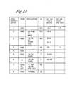
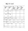
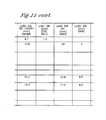
- FIG. 11is a table of data regarding blood vessel sizes of samplings of persons.
- FIGS. 1 and 1Adepict one embodiment of an intravascular catheter 20 adapted to exchange heat with a body fluid flowing through a body conduit of a patient.
- the catheter 20comprises an elongated body 22 having a substantially tubular configuration, having a proximal portion 26 with a proximal end 28 , and having a distal portion 30 with a distal end 32 .
- the distal end 32is disposed within the patient's body, and the proximal end 28 is disposed outside of the patient's body.
- One or more depth markings 60 62may be disposed on the elongated body 22 to indicate the length of a portion of the catheter 20 that is intubated into the patient.
- the depth markings 60 62are disposed at least on the proximal portion 26 of the elongated body 22 so that they are visible when the catheter 20 is intubated into the patient.
- the markings 60 62preferably indicate a length of the catheter 20 measured from each marking 60 62 to the distal tip 33 of the catheter 20 and may be disposed at spaced intervals, such as one-centimeter intervals.
- Each marking 60 62may comprise any symbol that may be understood to represent a length or relative length or degree of intubation.
- One marking 60is shown to comprise a numeral indicative of length (in centimeters, for example) from the marking 60 to the distal tip 33 of the catheter.
- Other markings 62may comprise dots, lines, hash marks or other marks.
- the elongated body 22may also include a distal indicator 64 that indicates the position of the distal end 32 or distal tip 33 of the elongated body 22 .
- the distal indicator 64preferably is disposed near the distal tip 33 of the elongated body 22 .
- the position of the distal indicator 64 inside the patientpreferably may be determined using conventional medical technology, such as with X-ray technology. Information regarding the position of the distal end 32 or distal tip 33 of the elongated body 22 may aid proper placement of the catheter 20 , so that the catheter 20 is inserted to a degree that maximizes the heat transfer rate without compromising physiological effects.
- the elongated body 22comprises an inflow lumen 32 , an outflow lumen 34 , and three infusion lumens 42 44 46 .
- the infusion lumens 42 44 46may serve a multiplicity of functions, including infusion of drugs such as chemotherapy, fluids and nutrition, guidewire support, access to syringes for sampling, and accommodation of various sensors, such as thermistors to monitor the patient, thus generally providing access to the central blood supply as dictated by the particular application.
- Each infusion lumen 42 44 46preferably has an infusion duct (infusion ducts are further described in connection with FIGS.
- an infusion lumensuch as the central infusion lumen 44 may be made of a different diameter than the other infusion lumens 42 46 in order to better support a guidewire for instance. While the catheter 20 depicted in FIG. 1 has three infusion lumens 42 44 46 , and while the preferred number of infusion lumens is three, four, or five infusion lumens, other numbers of infusion lumens are contemplated and may be suitable depending on the particular application.
- the catheter 20preferably is formed of a polymer material 23 that defines the various lumens 32 , 34 , 42 , 44 and 46 .
- a preferred material 23is polyurethane, although other materials, such as nylon, polyethylene, PEBAX, PVC, Tygon® or the like can also be used. Considerations in selecting the appropriate material 23 include biocompatibility, flexibility, temperature change compatibility, and resistance to buckling.
- At least one heat exchange element 24extends at least partially along the implantable, distal portion 30 of the elongated body 22 .
- this embodimentis shown to have only one heat exchange element 24 .
- a catheterhas two, three, or four heat exchange elements, as will be described below in connection with other embodiments. Further, a catheter may have more than four heat exchange elements.
- Heat exchange fluidflows within the catheter 20 to heat or cool a patient.
- the heat exchange fluidis remotely cooled or heated outside of the catheter 20 , such as by a temperature control system (not shown), and is conveyed between the catheter 20 and, for example, a temperature control system, via an inlet tube 52 a and an outlet tube 52 b .
- External access to the infusion lumens 42 44 46is supplied by infusion lumen fittings 74 76 78 .
- FIG. 2depicts a distal portion of a catheter 120 having three heat exchange elements 124 126 128 . Although this embodiment has three heat exchange elements 124 126 128 , the principles described herein apply to catheters having any number of heat exchange elements.
- a multiple heat exchange element configurationOne of the advantages of a multiple heat exchange element configuration is that the flow and temperature of heat exchange fluid that circulates in the catheter can be more easily controlled along the catheter such that a more even and balanced transfer of heat can be achieved. Further, multiple heat exchange elements may provide an increased surface area relative to embodiments having a single heat exchange element. Another advantage of a multiple heat exchange elements design is the ability of the catheter to bend and flex when placed in a curved vasculature.
- Each heat exchange element 124 126 128defines with the elongated body 122 a cavity 136 138 140 .
- Heat exchange fluid(as indicated by the arrows in FIG. 2) is circulated through the heat exchange elements 124 126 128 via the inflow lumen 132 and the outflow lumen 134 .
- the particular heat exchange fluid selectedis preferably biocompatible to avoid harm to the patient in the event of inadvertent rupture.
- suitable viscosity, heat exchange and material compatibility characteristicscan also be used. While less desired because it is not biocompatible, freon can alternatively be used.
- the fluidmay be either relatively cold or relatively warm, depending on whether patient cooling or heating is desired. While in the cavity 136 138 140 of the heat exchange element 124 126 128 , the heat exchange fluid serves to provide a cold or warm fluid on an inner surface of each heat exchange element 124 126 128 . With a body fluid, such as blood, flowing exteriorly of the heat exchange element 124 126 128 , heat transfer occurs across the heat exchange element 124 126 128 , effectively cooling or heating the body of the patient. The temperature of the heat exchange fluid is remotely controlled in order to achieve a desired patient target temperature or temperature range.
- the inflow lumen 132serves as an inflow channel supplying the heat exchange elements 124 126 128 with heat exchange fluid which is circulated through the catheter 20
- the outflow lumen 134serves as an outflow channel returning the heat exchange fluid from the heat exchange elements 124 126 128 to the catheter 120 .
- Each of the heat exchange elements 124 126 128may be formed from a piece of flexible sheet material or extruded tubing formed into a molded balloon of the desired shape and size and then bound or otherwise fixed to the elongated body 122 to form each cavity 136 138 140 .
- each heat exchange element 124 126 128is made of urethane, nylon, or PET and is thin-walled, i.e., has a wall thickness of less than three mils, and more preferably less than one and one-half mils.
- the heat exchange elements 124 126 128alternately may be made of metal such as steel, and may assume an appropriate configuration, such as an accordion-like configuration. Further, each heat exchange element 124 126 128 preferably is coated with an antimicrobial substance, as well as an anticlot substance, such as heparin.
- Each balloonpreferably is inflatable from a flattened configuration, wherein the balloon lies substantially flush with the elongated body 122 of the catheter 120 , to an operational configuration, wherein the heat exchange fluid inflates each balloon.
- the flattened configurationfacilitates insertion of the catheter 120 into the body of a patient.
- the elongated body 22includes an inflow duct 150 152 154 and an outflow duct 160 162 164 for each heat exchange element 124 126 128 .
- Each inflow duct 150 152 154is in fluid communication with the inflow lumen 132 .
- Each outflow duct 160 162 164is in fluid communication with the outflow lumen 134 .
- Heat exchange fluid introduced into the inflow lumen 132enters a cavity 136 138 140 of each heat exchange element 124 126 128 through an inflow duct 150 152 154 , flows through the heat exchange element 124 126 128 , exits the heat exchange element 124 126 128 through an outflow duct 160 162 164 , and flows through the outflow lumen 134 toward the proximal end of the catheter 120 .
- the inflow duct 150 152 154 of each heat exchange element 124 126 128preferably is positioned distally of the corresponding outflow duct 160 162 164 to provide countercurrent flow, which facilitates the maximum heat exchange between the heat exchange fluid and the body fluid, e.g., blood.
- the amount of flow within each of the heat exchange elements 124 126 128may be controlled by the size of the inflow ducts 150 152 154 and outflow ducts 160 162 164 .
- this flow controlis provided by the inflow ducts 150 152 154 ; the outflow ducts 160 162 164 are sized larger than their respective inflow ducts 150 152 154 so that they offer little resistance to flow.
- the inflow ducts 150 152 154are progressively smaller from the distal end to the proximal end.
- the inflow duct 150is larger than the inflow duct 152 which is in turn larger than the inflow duct 154 .
- the resistance to the flow of heat exchange fluid in the most distal balloonis less than that in the most proximal balloon. This helps distribute the coolest or warmest heat exchange fluid equally among all of the balloons regardless of their position along the elongated body 122 . Further information regarding the positions and relative sizes of inflow ducts and outflow ducts is disclosed in U.S. Pat. No. 6,126,684.
- the heat exchange fluidflows in parallel flow paths, such that fluid circulating through one of the balloons returns to the proximal end of the catheter without circulating through any other balloon.
- substantially equal heat exchange capacityis available in each balloon.
- heat exchange fluidmay flow in a serial flow path, such that fluid circulating through one of the balloons flows into another balloon before returning to the proximal end of the catheter.
- An embodiment having a serial flow pathis depicted in FIG. 3 .
- FIG. 3depicts an embodiment having two balloons, the principles set forth herein in connection with FIG. 3 may apply to catheters having any number of balloons.
- a serial flow pathmay be provided by, for example, arranging the inflow ducts 250 252 such that only one inflow duct 250 is in direct fluid communication with the inflow lumen 232 , and such that all other inflow ducts 252 are in direct fluid communication with the outflow lumen 234 .
- Fluid flow through the outflow lumen 234may be blocked by an obstruction 270 such that, for example, fluid flows into the outflow lumen 234 from a first balloon 224 through a first outflow duct 260 , flows in a proximal direction through the outflow lumen 234 toward a second inflow duct 252 , and flows through the second inflow duct 252 into a second balloon 226 .
- the obstruction 270may direct fluid into the second inflow duct 252 by blocking fluid flow through the outflow lumen 234 proximal of the second inflow duct 252 .
- various balloon shapesmay be employed, including but not limited to helical, cylindrical, and fluted shapes.
- the particular shape selecteddepends on the application and the desired heat exchange and other characteristics. Heat exchange is enhanced when either, or both, the body fluid or the heat exchange fluid is provided with well mixed flow. Mixing can be enhanced by providing irregular surfaces next to which either of these fluids flow. Further information regarding mixing is disclosed in U.S. Pat. No. 6,126,684.
- a catheterpreferably has one or more balloons having a helical shape.
- a helical balloonenhances mixing of the heat exchange fluid inside the balloon and increases residence time of the heat exchange fluid inside the balloon, increasing the heat exchange capacity of the balloon.
- the helical shapeis further believed to cause mixing of blood flowing past the helical-shaped balloon in the venous system, improving heat transfer by increasing the amount of blood exposed to the surface of the balloon.
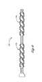
- FIG. 4depicts a catheter 320 having one balloon 324 with a helical shape.
- FIGS. 5A, 5 B, and 5 Cdistal portions of catheters 420 520 620 having one helical balloon 424 524 624 .
- Each of the helical balloons 424 524 624turns or wraps in a spiral or helix about an elongated body 422 522 622 of a catheter 420 520 620 .
- Each of the balloons 424 524 624has a pitch that is indicative of a distance between turns of the balloon 424 524 624 .
- An example of a distance between turnsis indicated by “p” in FIG. 5B.
- a preferred distance between each turn of the helixis 7.5 to 18 mm.
- a covering 450may surround portions of one or more balloons 424 to prevent coagulum from forming in the gap 446 between the turns of a balloon 424 or to minimize turbulence and shear which can be damaging to blood.
- the coveringpreferably 450 comprises an elastomeric material.
- a cathetermay have more than one helical balloon.
- FIG. 6depicts a catheter 720 having two helical balloons 724 726 .
- Each helical balloon 724 726may have either a fixed pitch, such that the distance between turns of the balloon 724 726 is substantially constant over the length of the balloon 724 726 .
- each helical balloon 724 726may have a variable pitch, such that the distance between turns of the balloon 724 726 varies over the length of the balloon 724 726 .
- the helical balloons 724 726may have the same or different pitches.
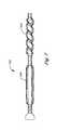
- a cathetermay have balloons of different shapes. As depicted in FIG. 7, for example, a catheter 820 may have a combination of one or more helical balloons 824 and one or more straight balloons 826 .
- a catheterpreferably has a size (e.g., length and diameter and/or cross-sectional area) that maximizes the heat transfer rate without causing harmful physiological effects. It is believed that in at least some blood vessels, flow of blood through the vessel begins to be reduced when approximately 50% of the blood vessel cross section is blocked.
- the cross-sectional size (e.g., diameter and/or area) of the balloonin combination with the cross-sectional size of the elongated body, preferably is no more than approximately 30% to 75% of the cross-sectional size of the blood vessel in which the balloon is inserted. This range may be modified to provide a suitable safety margin.
- the preferred size of a catheterwill vary with the size of each patient's vasculature. Data regarding blood vessel size for a sampling of persons is compiled in FIG. 11 . Using the maximum and minimum diameters and lengths, preferred diameters and lengths for each balloon were calculated so that no more than 30% to 75% of the vessel cross-section would be blocked by each balloon.
- the preferred diameters (indicated by way of example in FIG. 4 by “d 1 ”) of each balloon, from a distal-most to a proximal-most balloon,are approximately 5 to 9 mm, approximately 5 to 9 mm, and approximately 4 to 6 mm. Based on the data in FIG. 11, it is believed that such a three-balloon catheter would be especially suitable for use in the smallest 50% of patients.
- a four-balloon catheterwould be suitable for use in the largest 50% of patients.
- the preferred diameters, d 1would be, from a distal-most to a proximal-most balloon, approximately 8 to 12 mm, approximately 8 to 12 mm, approximately 5 to 9 mm, and approximately 4 to 6 mm.
- the cross-sectional size, d 2of the elongated body of the catheter defines an inner dimension of the balloons.
- the balloonstypically have a significantly larger diameter, d 1 , than the elongated body's diameter, d 2 .
- d 1the diameter of the inflated balloon, d 1
- d 2the diameter of the inflated balloon, d 1
- each balloonalso influences the heat transfer rate for each balloon.
- the balloonspreferably extend along substantially the entire length of the portion of the catheter that is intubated in the patient. Typically, this length is about 15 to 25 cm, as indicated by FIG. 11 .
- the preferable length of each balloonwill depend on the number of balloons used as well as the intubated length. For example, if the catheter has four balloons and is used in a relatively large patient, each balloon preferably has a length of approximately 58 mm. If the catheter has three balloons and is used in a relatively small patient, each balloon preferably has a length of approximately 58 mm. Different balloon lengths may be suitable in catheters using different numbers of balloons or used with patients of different sizes.
- a catheterpreferably has one or more infusion ducts to allow fluid communication between one or more infusion lumens and the patient's body fluid.
- the infusion ductspreferably are located in areas of the elongated body that are not covered by a heat exchange element so that the infusion ducts need not fluidly communicate through the heat exchange element. Referring to FIG. 5B by way of example, infusion ducts 534 536 may be disposed in gaps 546 548 between turns of a single helical balloon 524 .
- the heat exchange elementsare preferably spaced apart to define one or more gaps where the elongated body is exposed.
- Infusion ductsmay be located in such gaps, and also may be located adjacent to a single heat exchange element, such as distal of a distal-most balloon, or proximal of a proximal-most balloon.
- An infusion ductmay also be disposed at a distal tip of the catheter or disposed near the distal tip. Further, infusion ducts may be spaced at any combination of locations.
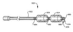
- a catheter 920 having two balloons 924 926 disposed about the elongated body 922may have a first infusion duct 980 disposed at a distal tip 934 of the catheter 920 , may have a second infusion duct 982 disposed in a gap between the two balloons 924 926 , may have a third infusion duct 984 disposed proximal of the balloon 926 , and/or may have a fourth infusion duct 986 disposed in a longitudinal side of the catheter 920 near a distal end 936 and between a balloon 924 and the first infusion duct 980 .
- the catheter 920may have one, all, or any combination of the above-described infusion ducts 980 982 984 986 , and may have infusion ducts in other locations as well.
- a catheter 1020 having three balloons 1024 1026 1028may have a first infusion duct 1080 disposed at a distal tip 1034 of the catheter 1020 , may have a second infusion duct 1082 disposed in a gap between two of the balloons 1024 1026 , may have a third infusion duct 1084 disposed in a gap between two other of the balloons 1026 1028 , may have a fourth infusion duct 1086 disposed proximal of the balloon 1028 , and/or may have a fifth infusion duct 1088 disposed in a longitudinal side of the catheter 1020 near a distal end 1036 and between a balloon 1024 and the first infusion duct 1080 .
- the catheter 1020may have one, all, or any combination of the above-described infusion ducts 1080 1082 1084 1086 1088 , and may have infusion ducts in other locations as well.
- a catheter 1120 having four balloons 1124 1126 1128 1130may have a first infusion duct 1180 disposed at a distal tip 1134 of the catheter 1120 , may have a second infusion duct 1182 disposed in a gap between two of the balloons 1124 1126 , may have a third infusion duct 1184 disposed in a gap between two other of the balloons 1126 1128 , may have a fourth infusion duct 1186 disposed in a gap between two other of the balloons 1128 1130 , may have a fifth infusion duct 1188 disposed proximal of the balloon 1128 , and/or may have a sixth infusion duct 1190 disposed in a longitudinal side of the catheter 1120 near a distal end 1136 and between a balloon 1124 and the first infusion duct 1180 .
- the catheter 1120may have one, all, or any combination of the above-described infusion ducts 1180 1182 11
- Providing multiple infusion ducts that are spaced apart on a catheterallows, for example, the simultaneously delivery different medications to the patient at different locations in the patient's bloodstream, which may be especially desirable where mixing of the medications in relatively high concentrations is desired to be avoided.
- a heat exchange elementmay comprise a balloon
- the heat exchange elementalternately may have a different configuration, such as an array of flexible hollow fibers through which the heat exchange fluid is circulated.
- hollow fibers and catheter systems having hollow fibersis disclosed in U.S. Pat. No. 6,165,207, which is hereby incorporated by reference as if fully set forth herein.
- the catheter 20preferably includes an anchor configured for affixing the catheter 20 to the patient.
- the anchormay comprise a suture fitting 80 .
- the suture fitting 80can be made integrally with the catheter 20 , or it can be made as a separate plastic fitting and engaged with the catheter 20 .
- the suture fitting 80includes two eyes 82 , 84 through which sutures can be inserted and engaged with the patient or with a bandage or tape or other structure that is engaged with the patient.
- An anchormay be especially desirable in cases in which the catheter is intubated for an extended period.
- the catheter-may be inserted percutaneously through a puncture or surgical cut near the groin.
- the cathetermay be inserted into the femoral and iliac veins, and the inferior vena cava (IVC), of a patient.
- the catheteris preferably inserted into blood vessels of the lower central venous system, such as the femoral and iliac veins and the inferior vena cava (IVC) because the volume of the lower central venous system is greater than that of the upper central venous system (jugular or subclavian, innominate, and superior vena cava), allowing a larger catheter (in both length and cross-sectional size) to be used.
- the catheter systems disclosed hereinmay be used in the upper central venous system.
- the size (e.g., cross-section and/or length) of the body conduit in which the catheter is to be intubatedmay be measured, and a catheter may be selected based on the size of the body conduit, so that the catheter maximizes the heat transfer rate without deleterious physiological effects to the patient.
- the heat exchange relationship between the catheter and the central venous system of the patientmay be maintained for a prolonged duration—for example, from about one hour to about twenty-nine days.
- catheter systems disclosed hereinmay be used in connection with systems for treating cardiac arrest that are disclosed in U.S. Pat. No. 6,149,670, which is hereby incorporated by reference as if fully set forth herein.
Landscapes
- Health & Medical Sciences (AREA)
- Vascular Medicine (AREA)
- Thermal Sciences (AREA)
- Engineering & Computer Science (AREA)
- Biomedical Technology (AREA)
- Heart & Thoracic Surgery (AREA)
- Physics & Mathematics (AREA)
- Life Sciences & Earth Sciences (AREA)
- Animal Behavior & Ethology (AREA)
- General Health & Medical Sciences (AREA)
- Public Health (AREA)
- Veterinary Medicine (AREA)
- Infusion, Injection, And Reservoir Apparatuses (AREA)
Abstract
Description
Claims (93)
Priority Applications (1)
| Application Number | Priority Date | Filing Date | Title |
|---|---|---|---|
| US09/816,645US6719724B1 (en) | 1999-02-19 | 2001-03-23 | Central venous line catheter having multiple heat exchange elements and multiple infusion lumens |
Applications Claiming Priority (2)
| Application Number | Priority Date | Filing Date | Title |
|---|---|---|---|
| US25310999A | 1999-02-19 | 1999-02-19 | |
| US09/816,645US6719724B1 (en) | 1999-02-19 | 2001-03-23 | Central venous line catheter having multiple heat exchange elements and multiple infusion lumens |
Related Parent Applications (1)
| Application Number | Title | Priority Date | Filing Date |
|---|---|---|---|
| US25310999AContinuation-In-Part | 1998-04-21 | 1999-02-19 |
Publications (1)
| Publication Number | Publication Date |
|---|---|
| US6719724B1true US6719724B1 (en) | 2004-04-13 |
Family
ID=46204063
Family Applications (1)
| Application Number | Title | Priority Date | Filing Date |
|---|---|---|---|
| US09/816,645Expired - LifetimeUS6719724B1 (en) | 1999-02-19 | 2001-03-23 | Central venous line catheter having multiple heat exchange elements and multiple infusion lumens |
Country Status (1)
| Country | Link |
|---|---|
| US (1) | US6719724B1 (en) |
Cited By (80)
| Publication number | Priority date | Publication date | Assignee | Title |
|---|---|---|---|---|
| US20040199114A1 (en)* | 2003-04-01 | 2004-10-07 | Alsius Corporation | Intravascular heat exchange catheter with tissue preservative |
| US20050222653A1 (en)* | 1998-04-21 | 2005-10-06 | Alsius Corporation | Indwelling heat exchange catheter and method of using same |
| US20050283181A1 (en)* | 2004-06-21 | 2005-12-22 | Sundaram Ravikumar | Catheter device and method for selective occlusion of arteries of the descending aorta |
| US20060064146A1 (en)* | 2004-09-17 | 2006-03-23 | Collins Kenneth A | Heating/cooling system for indwelling heat exchange catheter |
| US20060190062A1 (en)* | 2005-02-23 | 2006-08-24 | Worthen William J | System and method for reducing shivering when using external cooling pads |
| US20060190066A1 (en)* | 2005-02-23 | 2006-08-24 | Worthen William J | System and method for bringing hypothermia rapidly onboard |
| US20060200215A1 (en)* | 2005-03-01 | 2006-09-07 | Collins Kenneth A | System and method for treating cardiac arrest and myocardial infarction |
| US20060235496A1 (en)* | 2005-04-18 | 2006-10-19 | Collins Kenneth A | External heat exchange pad for patient |
| US20060276864A1 (en)* | 2005-06-03 | 2006-12-07 | Alsius Corporation | Systems and methods for sensing patient temperature in temperature management system |
| US20060293732A1 (en)* | 2005-06-27 | 2006-12-28 | Collins Kenneth A | Thermoelectric cooler (TEC) heat exchanger for intravascular heat exchange catheter |
| US20070000278A1 (en)* | 2005-07-01 | 2007-01-04 | Collins Kenneth A | Primary heat exchanger for patient temperature control |
| US20070016270A1 (en)* | 2005-07-14 | 2007-01-18 | Stelica Stelea | System and method for leak detection in external cooling pad |
| US20070106247A1 (en)* | 2005-10-21 | 2007-05-10 | Ceeben Systems, Inc. | Method and apparatus for peritoneal hypothermia and/or resuscitation |
| US20070185445A1 (en)* | 2006-02-06 | 2007-08-09 | Cryocath Technologies Inc. | Cryo-perfusion balloon device |
| US20080119788A1 (en)* | 2006-11-21 | 2008-05-22 | Suzanne Winter | Temperature management system and method for burn patients |
| US20080249467A1 (en)* | 2007-04-05 | 2008-10-09 | Daniel Rogers Burnett | Device and Method for Safe Access to a Body Cavity |
| US20080287919A1 (en)* | 2007-05-18 | 2008-11-20 | David Searl Kimball | System and method for effecting non-standard fluid line connections |
| US20090076573A1 (en)* | 2007-07-09 | 2009-03-19 | Daniel Rogers Burnett | Hypothermia Devices and Methods |
| US20090131919A1 (en)* | 2007-11-21 | 2009-05-21 | Christopher Davey | Implantable medical device |
| US20090275889A1 (en)* | 2008-05-01 | 2009-11-05 | Sundaram Ravikumar | Intravascular Catheter Device for Selective Occlusion of Iliac Vasculature |
| US20100016835A1 (en)* | 2008-07-16 | 2010-01-21 | Christopher Davey | Modular implantable medical device |
| US20100121159A1 (en)* | 2008-11-07 | 2010-05-13 | Daniel Rogers Burnett | Devices and Methods for Monitoring Core Temperature and an Intraperitoneal Parameter |
| US20100204765A1 (en)* | 2009-02-06 | 2010-08-12 | Hall Gregory W | Method and Apparatus for Inducing Therapeutic Hypothermia |
| US7794407B2 (en) | 2006-10-23 | 2010-09-14 | Bard Access Systems, Inc. | Method of locating the tip of a central venous catheter |
| US20100249712A1 (en)* | 2009-03-27 | 2010-09-30 | Christopher Davey | Deformable medical implant |
| US7822485B2 (en) | 2006-09-25 | 2010-10-26 | Zoll Circulation, Inc. | Method and apparatus for spinal cooling |
| US7867266B2 (en) | 2006-11-13 | 2011-01-11 | Zoll Circulation, Inc. | Temperature management system with assist mode for use with heart-lung machine |
| US20110046547A1 (en)* | 2002-11-12 | 2011-02-24 | Mantle Ross E | Device for the Extravascular Recirculation of Liquid in Body Cavities |
| US20110125129A1 (en)* | 2001-07-27 | 2011-05-26 | Saab Mark A | Medical device with adjustable tissue ingrowth cuff |
| US8100880B2 (en) | 2007-04-05 | 2012-01-24 | Velomedix, Inc. | Automated therapy system and method |
| US20120053614A1 (en)* | 2010-08-31 | 2012-03-01 | Vibha AGARWAL | Vascular dilator for controlling blood flow in a blood vessel |
| US8128595B2 (en) | 1998-04-21 | 2012-03-06 | Zoll Circulation, Inc. | Method for a central venous line catheter having a temperature control system |
| US8353893B2 (en) | 2007-03-07 | 2013-01-15 | Zoll Circulation, Inc. | System and method for rapidly cooling cardiac arrest patient |
| US8388546B2 (en) | 2006-10-23 | 2013-03-05 | Bard Access Systems, Inc. | Method of locating the tip of a central venous catheter |
| US8388541B2 (en) | 2007-11-26 | 2013-03-05 | C. R. Bard, Inc. | Integrated system for intravascular placement of a catheter |
| US8437833B2 (en) | 2008-10-07 | 2013-05-07 | Bard Access Systems, Inc. | Percutaneous magnetic gastrostomy |
| US8478382B2 (en) | 2008-02-11 | 2013-07-02 | C. R. Bard, Inc. | Systems and methods for positioning a catheter |
| USD699359S1 (en) | 2011-08-09 | 2014-02-11 | C. R. Bard, Inc. | Ultrasound probe head |
| US8781555B2 (en) | 2007-11-26 | 2014-07-15 | C. R. Bard, Inc. | System for placement of a catheter including a signal-generating stylet |
| US8784336B2 (en) | 2005-08-24 | 2014-07-22 | C. R. Bard, Inc. | Stylet apparatuses and methods of manufacture |
| US8801693B2 (en) | 2010-10-29 | 2014-08-12 | C. R. Bard, Inc. | Bioimpedance-assisted placement of a medical device |
| US8849382B2 (en) | 2007-11-26 | 2014-09-30 | C. R. Bard, Inc. | Apparatus and display methods relating to intravascular placement of a catheter |
| CN104117128A (en)* | 2014-07-18 | 2014-10-29 | 北京普益盛济科技有限公司 | Balloon catheter for mild hypothermia therapy |
| USD724745S1 (en) | 2011-08-09 | 2015-03-17 | C. R. Bard, Inc. | Cap for an ultrasound probe |
| US9125578B2 (en) | 2009-06-12 | 2015-09-08 | Bard Access Systems, Inc. | Apparatus and method for catheter navigation and tip location |
| EP2932946A1 (en)* | 2014-04-17 | 2015-10-21 | seiratherm GmbH | Apparatus, system and method for controlling a temperature of a patient |
| US9211107B2 (en) | 2011-11-07 | 2015-12-15 | C. R. Bard, Inc. | Ruggedized ultrasound hydrogel insert |
| US9332999B2 (en) | 2012-08-13 | 2016-05-10 | Covidien Lp | Apparatus and methods for clot disruption and evacuation |
| US9332998B2 (en) | 2012-08-13 | 2016-05-10 | Covidien Lp | Apparatus and methods for clot disruption and evacuation |
| US9339206B2 (en) | 2009-06-12 | 2016-05-17 | Bard Access Systems, Inc. | Adaptor for endovascular electrocardiography |
| US9445734B2 (en) | 2009-06-12 | 2016-09-20 | Bard Access Systems, Inc. | Devices and methods for endovascular electrography |
| US9456766B2 (en) | 2007-11-26 | 2016-10-04 | C. R. Bard, Inc. | Apparatus for use with needle insertion guidance system |
| US9492097B2 (en) | 2007-11-26 | 2016-11-15 | C. R. Bard, Inc. | Needle length determination and calibration for insertion guidance system |
| US9521961B2 (en) | 2007-11-26 | 2016-12-20 | C. R. Bard, Inc. | Systems and methods for guiding a medical instrument |
| US9532724B2 (en) | 2009-06-12 | 2017-01-03 | Bard Access Systems, Inc. | Apparatus and method for catheter navigation using endovascular energy mapping |
| US9554716B2 (en) | 2007-11-26 | 2017-01-31 | C. R. Bard, Inc. | Insertion guidance system for needles and medical components |
| US9622670B2 (en) | 2010-07-09 | 2017-04-18 | Potrero Medical, Inc. | Method and apparatus for pressure measurement |
| US9636031B2 (en) | 2007-11-26 | 2017-05-02 | C.R. Bard, Inc. | Stylets for use with apparatus for intravascular placement of a catheter |
| US9649048B2 (en) | 2007-11-26 | 2017-05-16 | C. R. Bard, Inc. | Systems and methods for breaching a sterile field for intravascular placement of a catheter |
| US9839372B2 (en) | 2014-02-06 | 2017-12-12 | C. R. Bard, Inc. | Systems and methods for guidance and placement of an intravascular device |
| US9901714B2 (en) | 2008-08-22 | 2018-02-27 | C. R. Bard, Inc. | Catheter assembly including ECG sensor and magnetic assemblies |
| CN108211095A (en)* | 2018-01-12 | 2018-06-29 | 佛山博骏生物科技有限公司 | A kind of conduit of intravascular mild hypothermia therapy |
| US10046139B2 (en) | 2010-08-20 | 2018-08-14 | C. R. Bard, Inc. | Reconfirmation of ECG-assisted catheter tip placement |
| CN109431485A (en)* | 2018-11-06 | 2019-03-08 | 天津大学 | A kind of velocity of blood flow detection device applied in foley's tube |
| US10272236B2 (en) | 2009-03-27 | 2019-04-30 | Marvao Medical Devices Ltd | Deformable medical implant |
| US10349890B2 (en) | 2015-06-26 | 2019-07-16 | C. R. Bard, Inc. | Connector interface for ECG-based catheter positioning system |
| US10449330B2 (en) | 2007-11-26 | 2019-10-22 | C. R. Bard, Inc. | Magnetic element-equipped needle assemblies |
| CN110461282A (en)* | 2017-02-02 | 2019-11-15 | 佐尔循环服务系统公司 | Devices, systems, and methods for intravascular temperature control |
| US10524691B2 (en) | 2007-11-26 | 2020-01-07 | C. R. Bard, Inc. | Needle assembly including an aligned magnetic element |
| US10639008B2 (en) | 2009-10-08 | 2020-05-05 | C. R. Bard, Inc. | Support and cover structures for an ultrasound probe head |
| US10702678B2 (en) | 2013-10-14 | 2020-07-07 | Gerstner Medical, Llc | Multiple balloon venous occlusion catheter |
| US10751509B2 (en) | 2007-11-26 | 2020-08-25 | C. R. Bard, Inc. | Iconic representations for guidance of an indwelling medical device |
| US10820885B2 (en) | 2012-06-15 | 2020-11-03 | C. R. Bard, Inc. | Apparatus and methods for detection of a removable cap on an ultrasound probe |
| US10973584B2 (en) | 2015-01-19 | 2021-04-13 | Bard Access Systems, Inc. | Device and method for vascular access |
| US10992079B2 (en) | 2018-10-16 | 2021-04-27 | Bard Access Systems, Inc. | Safety-equipped connection systems and methods thereof for establishing electrical connections |
| US11000207B2 (en) | 2016-01-29 | 2021-05-11 | C. R. Bard, Inc. | Multiple coil system for tracking a medical device |
| WO2021102301A1 (en)* | 2019-11-20 | 2021-05-27 | B2M Medical, Inc. | Systems and methods for treatment of visceral fat |
| US11103213B2 (en) | 2009-10-08 | 2021-08-31 | C. R. Bard, Inc. | Spacers for use with an ultrasound probe |
| US11446177B2 (en) | 2005-10-21 | 2022-09-20 | Theranova, Llc | Method and apparatus for peritoneal oxygenation |
| US12433657B2 (en) | 2022-01-04 | 2025-10-07 | B2M Medical, Inc. | Planar-shaped thermal balloon for mesenteric fat reduction |
Citations (23)
| Publication number | Priority date | Publication date | Assignee | Title |
|---|---|---|---|---|
| US4164943A (en)* | 1977-09-30 | 1979-08-21 | Thoratec Laboratories Corporation | Catheter anchor |
| US4941475A (en)* | 1988-08-30 | 1990-07-17 | Spectramed, Inc. | Thermodilution by heat exchange |
| US5122113A (en) | 1991-03-27 | 1992-06-16 | Hattler Brack G | Inflatable percutaneous oxygenator |
| US5182317A (en) | 1988-06-08 | 1993-01-26 | Cardiopulmonics, Inc. | Multifunctional thrombo-resistant coatings and methods of manufacture |
| US5207640A (en) | 1991-03-27 | 1993-05-04 | Hattler Brack G | Method of anesthetizing a patient |
| US5242390A (en) | 1991-05-03 | 1993-09-07 | Goldrath Milton H | Endometrium coagulating surgical method for thermal destruction of the endometrium |
| US5262451A (en) | 1988-06-08 | 1993-11-16 | Cardiopulmonics, Inc. | Multifunctional thrombo-resistant coatings and methods of manufacture |
| US5271743A (en) | 1991-03-27 | 1993-12-21 | Hattler Brack G | System to optimize the transfer of gas through membranes |
| US5279598A (en) | 1991-07-24 | 1994-01-18 | Sheaff Charles M | Patient warming methods |
| US5383856A (en) | 1993-03-19 | 1995-01-24 | Bersin; Robert M. | Helical spiral balloon catheter |
| US5423763A (en) | 1993-06-17 | 1995-06-13 | Pacesetter, Inc. | Protective, visible suture sleeve for anchoring transvenous lead bodies |
| US5478309A (en) | 1994-05-27 | 1995-12-26 | William P. Sweezer, Jr. | Catheter system and method for providing cardiopulmonary bypass pump support during heart surgery |
| US5501663A (en) | 1993-07-02 | 1996-03-26 | Medtronic Electromedics, Inc. | Inflatable percutaneous oxygenator with transverse hollow fibers |
| US5549559A (en) | 1990-03-22 | 1996-08-27 | Argomed Ltd. | Thermal treatment apparatus |
| US5549552A (en) | 1995-03-02 | 1996-08-27 | Scimed Life Systems, Inc. | Balloon dilation catheter with improved pushability, trackability and crossability |
| US5674287A (en)* | 1988-08-24 | 1997-10-07 | Endoluminal Therapeutics, Inc. | Biodegradable polymeric endoluminal sealing process, apparatus and polymeric product for use therein |
| US5797869A (en) | 1987-12-22 | 1998-08-25 | Vas-Cath Incorporated | Multiple lumen catheter |
| US5807342A (en) | 1996-02-29 | 1998-09-15 | Becton Dickinson And Company | Catheter with improved tape down wing |
| US5879316A (en) | 1990-12-28 | 1999-03-09 | University Of Pittsburgh Of The Commonwealth System Of Higher Education | Portable and modular cardiopulmonary bypass apparatus and associated aortic balloon catheter and associated method |
| US5902274A (en) | 1996-08-02 | 1999-05-11 | Nissho Corporation | Catheter assembly |
| US6190356B1 (en) | 1997-10-20 | 2001-02-20 | Robert M. Bersin | Helical spiral balloon catheter |
| US6231594B1 (en) | 1999-08-11 | 2001-05-15 | Radiant Medical, Inc. | Method of controlling body temperature while reducing shivering |
| US6287326B1 (en) | 1999-08-02 | 2001-09-11 | Alsius Corporation | Catheter with coiled multi-lumen heat transfer extension |
- 2001
- 2001-03-23USUS09/816,645patent/US6719724B1/ennot_activeExpired - Lifetime
Patent Citations (25)
| Publication number | Priority date | Publication date | Assignee | Title |
|---|---|---|---|---|
| US4164943A (en)* | 1977-09-30 | 1979-08-21 | Thoratec Laboratories Corporation | Catheter anchor |
| US5797869A (en) | 1987-12-22 | 1998-08-25 | Vas-Cath Incorporated | Multiple lumen catheter |
| US5182317A (en) | 1988-06-08 | 1993-01-26 | Cardiopulmonics, Inc. | Multifunctional thrombo-resistant coatings and methods of manufacture |
| US5262451A (en) | 1988-06-08 | 1993-11-16 | Cardiopulmonics, Inc. | Multifunctional thrombo-resistant coatings and methods of manufacture |
| US5674287A (en)* | 1988-08-24 | 1997-10-07 | Endoluminal Therapeutics, Inc. | Biodegradable polymeric endoluminal sealing process, apparatus and polymeric product for use therein |
| US4941475A (en)* | 1988-08-30 | 1990-07-17 | Spectramed, Inc. | Thermodilution by heat exchange |
| US5549559A (en) | 1990-03-22 | 1996-08-27 | Argomed Ltd. | Thermal treatment apparatus |
| US5906588A (en) | 1990-12-28 | 1999-05-25 | Cardeon Corporation | Portable and modular cardiopulmonary bypass apparatus and associated aortic balloon and associated method |
| US5879316A (en) | 1990-12-28 | 1999-03-09 | University Of Pittsburgh Of The Commonwealth System Of Higher Education | Portable and modular cardiopulmonary bypass apparatus and associated aortic balloon catheter and associated method |
| US5207640A (en) | 1991-03-27 | 1993-05-04 | Hattler Brack G | Method of anesthetizing a patient |
| US5271743A (en) | 1991-03-27 | 1993-12-21 | Hattler Brack G | System to optimize the transfer of gas through membranes |
| US5122113A (en) | 1991-03-27 | 1992-06-16 | Hattler Brack G | Inflatable percutaneous oxygenator |
| US5242390A (en) | 1991-05-03 | 1993-09-07 | Goldrath Milton H | Endometrium coagulating surgical method for thermal destruction of the endometrium |
| US5279598A (en) | 1991-07-24 | 1994-01-18 | Sheaff Charles M | Patient warming methods |
| US5383856A (en) | 1993-03-19 | 1995-01-24 | Bersin; Robert M. | Helical spiral balloon catheter |
| US5423763A (en) | 1993-06-17 | 1995-06-13 | Pacesetter, Inc. | Protective, visible suture sleeve for anchoring transvenous lead bodies |
| US5501663A (en) | 1993-07-02 | 1996-03-26 | Medtronic Electromedics, Inc. | Inflatable percutaneous oxygenator with transverse hollow fibers |
| US5800375A (en) | 1994-05-27 | 1998-09-01 | Heartport, Inc. | Catheter system and method for providing cardiopulmonary bypass pump support during heart surgery |
| US5478309A (en) | 1994-05-27 | 1995-12-26 | William P. Sweezer, Jr. | Catheter system and method for providing cardiopulmonary bypass pump support during heart surgery |
| US5549552A (en) | 1995-03-02 | 1996-08-27 | Scimed Life Systems, Inc. | Balloon dilation catheter with improved pushability, trackability and crossability |
| US5807342A (en) | 1996-02-29 | 1998-09-15 | Becton Dickinson And Company | Catheter with improved tape down wing |
| US5902274A (en) | 1996-08-02 | 1999-05-11 | Nissho Corporation | Catheter assembly |
| US6190356B1 (en) | 1997-10-20 | 2001-02-20 | Robert M. Bersin | Helical spiral balloon catheter |
| US6287326B1 (en) | 1999-08-02 | 2001-09-11 | Alsius Corporation | Catheter with coiled multi-lumen heat transfer extension |
| US6231594B1 (en) | 1999-08-11 | 2001-05-15 | Radiant Medical, Inc. | Method of controlling body temperature while reducing shivering |
Cited By (153)
| Publication number | Priority date | Publication date | Assignee | Title |
|---|---|---|---|---|
| US20050222653A1 (en)* | 1998-04-21 | 2005-10-06 | Alsius Corporation | Indwelling heat exchange catheter and method of using same |
| US7857781B2 (en) | 1998-04-21 | 2010-12-28 | Zoll Circulation, Inc. | Indwelling heat exchange catheter and method of using same |
| US8128595B2 (en) | 1998-04-21 | 2012-03-06 | Zoll Circulation, Inc. | Method for a central venous line catheter having a temperature control system |
| US20110125129A1 (en)* | 2001-07-27 | 2011-05-26 | Saab Mark A | Medical device with adjustable tissue ingrowth cuff |
| US8979806B2 (en) | 2001-07-27 | 2015-03-17 | Mark A. Saab | Medical device with adjustable tissue ingrowth cuff |
| US9737699B2 (en) | 2001-07-27 | 2017-08-22 | Mark A. Saab | Medical hub and method of using same |
| US20110046547A1 (en)* | 2002-11-12 | 2011-02-24 | Mantle Ross E | Device for the Extravascular Recirculation of Liquid in Body Cavities |
| US20040199114A1 (en)* | 2003-04-01 | 2004-10-07 | Alsius Corporation | Intravascular heat exchange catheter with tissue preservative |
| US20110034948A1 (en)* | 2004-06-21 | 2011-02-10 | Sundaram Ravikumar | Catheter Device and Method for Selective Occlusion of Arteries of the Descending Aorta |
| US7771448B2 (en)* | 2004-06-21 | 2010-08-10 | Arvik Enterprises, Llc | Catheter device and method for selective occlusion of arteries of the descending aorta |
| US8211138B2 (en)* | 2004-06-21 | 2012-07-03 | Arvik Enterprises, Llc | Catheter device and method for selective occlusion of arteries of the descending aorta |
| US20050283181A1 (en)* | 2004-06-21 | 2005-12-22 | Sundaram Ravikumar | Catheter device and method for selective occlusion of arteries of the descending aorta |
| US20060064146A1 (en)* | 2004-09-17 | 2006-03-23 | Collins Kenneth A | Heating/cooling system for indwelling heat exchange catheter |
| US20060190066A1 (en)* | 2005-02-23 | 2006-08-24 | Worthen William J | System and method for bringing hypothermia rapidly onboard |
| US20060190062A1 (en)* | 2005-02-23 | 2006-08-24 | Worthen William J | System and method for reducing shivering when using external cooling pads |
| US7425216B2 (en) | 2005-03-01 | 2008-09-16 | Alsius Corporation | System and method for treating cardiac arrest and myocardial infarction |
| US20060200215A1 (en)* | 2005-03-01 | 2006-09-07 | Collins Kenneth A | System and method for treating cardiac arrest and myocardial infarction |
| US7892269B2 (en) | 2005-04-18 | 2011-02-22 | Zoll Circulation, Inc. | External heat exchange pad for patient |
| US11547601B2 (en) | 2005-04-18 | 2023-01-10 | Zoll Circulation, Inc. | System and method for bringing hypothermia rapidly onboard |
| US20060235496A1 (en)* | 2005-04-18 | 2006-10-19 | Collins Kenneth A | External heat exchange pad for patient |
| US20060276864A1 (en)* | 2005-06-03 | 2006-12-07 | Alsius Corporation | Systems and methods for sensing patient temperature in temperature management system |
| US20060293732A1 (en)* | 2005-06-27 | 2006-12-28 | Collins Kenneth A | Thermoelectric cooler (TEC) heat exchanger for intravascular heat exchange catheter |
| US20070000278A1 (en)* | 2005-07-01 | 2007-01-04 | Collins Kenneth A | Primary heat exchanger for patient temperature control |
| US7181927B2 (en) | 2005-07-01 | 2007-02-27 | Alsius Corporation | Primary heat exchanger for patient temperature control |
| US7951182B2 (en) | 2005-07-14 | 2011-05-31 | Zoll Circulation, Inc. | System and method for leak detection in external cooling pad |
| US20070016270A1 (en)* | 2005-07-14 | 2007-01-18 | Stelica Stelea | System and method for leak detection in external cooling pad |
| US8784336B2 (en) | 2005-08-24 | 2014-07-22 | C. R. Bard, Inc. | Stylet apparatuses and methods of manufacture |
| US10004875B2 (en) | 2005-08-24 | 2018-06-26 | C. R. Bard, Inc. | Stylet apparatuses and methods of manufacture |
| US11207496B2 (en) | 2005-08-24 | 2021-12-28 | C. R. Bard, Inc. | Stylet apparatuses and methods of manufacture |
| US20070106247A1 (en)* | 2005-10-21 | 2007-05-10 | Ceeben Systems, Inc. | Method and apparatus for peritoneal hypothermia and/or resuscitation |
| US8672884B2 (en) | 2005-10-21 | 2014-03-18 | Velomedix, Inc. | Method and apparatus for peritoneal hypothermia and/or resuscitation |
| US11446177B2 (en) | 2005-10-21 | 2022-09-20 | Theranova, Llc | Method and apparatus for peritoneal oxygenation |
| US9937332B2 (en)* | 2006-02-06 | 2018-04-10 | Medtronic Cryocath Lp | Cryo-perfusion balloon device |
| US20070185445A1 (en)* | 2006-02-06 | 2007-08-09 | Cryocath Technologies Inc. | Cryo-perfusion balloon device |
| US9180042B2 (en) | 2006-09-25 | 2015-11-10 | Zoll Circulation, Inc. | Method and apparatus for spinal cooling |
| US7822485B2 (en) | 2006-09-25 | 2010-10-26 | Zoll Circulation, Inc. | Method and apparatus for spinal cooling |
| US9265443B2 (en) | 2006-10-23 | 2016-02-23 | Bard Access Systems, Inc. | Method of locating the tip of a central venous catheter |
| US9345422B2 (en) | 2006-10-23 | 2016-05-24 | Bard Acess Systems, Inc. | Method of locating the tip of a central venous catheter |
| US8512256B2 (en) | 2006-10-23 | 2013-08-20 | Bard Access Systems, Inc. | Method of locating the tip of a central venous catheter |
| US7794407B2 (en) | 2006-10-23 | 2010-09-14 | Bard Access Systems, Inc. | Method of locating the tip of a central venous catheter |
| US8774907B2 (en) | 2006-10-23 | 2014-07-08 | Bard Access Systems, Inc. | Method of locating the tip of a central venous catheter |
| US9833169B2 (en) | 2006-10-23 | 2017-12-05 | Bard Access Systems, Inc. | Method of locating the tip of a central venous catheter |
| US8388546B2 (en) | 2006-10-23 | 2013-03-05 | Bard Access Systems, Inc. | Method of locating the tip of a central venous catheter |
| US8858455B2 (en) | 2006-10-23 | 2014-10-14 | Bard Access Systems, Inc. | Method of locating the tip of a central venous catheter |
| US7867266B2 (en) | 2006-11-13 | 2011-01-11 | Zoll Circulation, Inc. | Temperature management system with assist mode for use with heart-lung machine |
| US20080119788A1 (en)* | 2006-11-21 | 2008-05-22 | Suzanne Winter | Temperature management system and method for burn patients |
| US7892270B2 (en) | 2006-11-21 | 2011-02-22 | Zoll Circulation Inc. | Temperature management system and method for burn patients |
| US8353893B2 (en) | 2007-03-07 | 2013-01-15 | Zoll Circulation, Inc. | System and method for rapidly cooling cardiac arrest patient |
| US8100880B2 (en) | 2007-04-05 | 2012-01-24 | Velomedix, Inc. | Automated therapy system and method |
| US8480648B2 (en) | 2007-04-05 | 2013-07-09 | Velomedix, Inc. | Automated therapy system and method |
| US20080249467A1 (en)* | 2007-04-05 | 2008-10-09 | Daniel Rogers Burnett | Device and Method for Safe Access to a Body Cavity |
| US11800992B2 (en) | 2007-04-05 | 2023-10-31 | Theranova, Llc | Device and method for safe access and automated therapy |
| US20080287919A1 (en)* | 2007-05-18 | 2008-11-20 | David Searl Kimball | System and method for effecting non-standard fluid line connections |
| US11717665B2 (en) | 2007-05-18 | 2023-08-08 | Zoll Circulation, Inc. | System and method for effecting non-standard fluid line connections |
| US9737692B2 (en) | 2007-05-18 | 2017-08-22 | Zoll Circulation, Inc. | System and method for effecting non-standard fluid line connections |
| US8439960B2 (en) | 2007-07-09 | 2013-05-14 | Velomedix, Inc. | Hypothermia devices and methods |
| US20090076573A1 (en)* | 2007-07-09 | 2009-03-19 | Daniel Rogers Burnett | Hypothermia Devices and Methods |
| US20090131919A1 (en)* | 2007-11-21 | 2009-05-21 | Christopher Davey | Implantable medical device |
| US10602958B2 (en) | 2007-11-26 | 2020-03-31 | C. R. Bard, Inc. | Systems and methods for guiding a medical instrument |
| US10231753B2 (en) | 2007-11-26 | 2019-03-19 | C. R. Bard, Inc. | Insertion guidance system for needles and medical components |
| US8849382B2 (en) | 2007-11-26 | 2014-09-30 | C. R. Bard, Inc. | Apparatus and display methods relating to intravascular placement of a catheter |
| US11707205B2 (en) | 2007-11-26 | 2023-07-25 | C. R. Bard, Inc. | Integrated system for intravascular placement of a catheter |
| US11529070B2 (en) | 2007-11-26 | 2022-12-20 | C. R. Bard, Inc. | System and methods for guiding a medical instrument |
| US9999371B2 (en) | 2007-11-26 | 2018-06-19 | C. R. Bard, Inc. | Integrated system for intravascular placement of a catheter |
| US10105121B2 (en) | 2007-11-26 | 2018-10-23 | C. R. Bard, Inc. | System for placement of a catheter including a signal-generating stylet |
| US9681823B2 (en) | 2007-11-26 | 2017-06-20 | C. R. Bard, Inc. | Integrated system for intravascular placement of a catheter |
| US8388541B2 (en) | 2007-11-26 | 2013-03-05 | C. R. Bard, Inc. | Integrated system for intravascular placement of a catheter |
| US11134915B2 (en) | 2007-11-26 | 2021-10-05 | C. R. Bard, Inc. | System for placement of a catheter including a signal-generating stylet |
| US11123099B2 (en) | 2007-11-26 | 2021-09-21 | C. R. Bard, Inc. | Apparatus for use with needle insertion guidance system |
| US9649048B2 (en) | 2007-11-26 | 2017-05-16 | C. R. Bard, Inc. | Systems and methods for breaching a sterile field for intravascular placement of a catheter |
| US9636031B2 (en) | 2007-11-26 | 2017-05-02 | C.R. Bard, Inc. | Stylets for use with apparatus for intravascular placement of a catheter |
| US10966630B2 (en) | 2007-11-26 | 2021-04-06 | C. R. Bard, Inc. | Integrated system for intravascular placement of a catheter |
| US11779240B2 (en) | 2007-11-26 | 2023-10-10 | C. R. Bard, Inc. | Systems and methods for breaching a sterile field for intravascular placement of a catheter |
| US10849695B2 (en) | 2007-11-26 | 2020-12-01 | C. R. Bard, Inc. | Systems and methods for breaching a sterile field for intravascular placement of a catheter |
| US10751509B2 (en) | 2007-11-26 | 2020-08-25 | C. R. Bard, Inc. | Iconic representations for guidance of an indwelling medical device |
| US10165962B2 (en) | 2007-11-26 | 2019-01-01 | C. R. Bard, Inc. | Integrated systems for intravascular placement of a catheter |
| US10524691B2 (en) | 2007-11-26 | 2020-01-07 | C. R. Bard, Inc. | Needle assembly including an aligned magnetic element |
| US10449330B2 (en) | 2007-11-26 | 2019-10-22 | C. R. Bard, Inc. | Magnetic element-equipped needle assemblies |
| US8781555B2 (en) | 2007-11-26 | 2014-07-15 | C. R. Bard, Inc. | System for placement of a catheter including a signal-generating stylet |
| US10342575B2 (en) | 2007-11-26 | 2019-07-09 | C. R. Bard, Inc. | Apparatus for use with needle insertion guidance system |
| US9554716B2 (en) | 2007-11-26 | 2017-01-31 | C. R. Bard, Inc. | Insertion guidance system for needles and medical components |
| US9549685B2 (en) | 2007-11-26 | 2017-01-24 | C. R. Bard, Inc. | Apparatus and display methods relating to intravascular placement of a catheter |
| US9456766B2 (en) | 2007-11-26 | 2016-10-04 | C. R. Bard, Inc. | Apparatus for use with needle insertion guidance system |
| US9492097B2 (en) | 2007-11-26 | 2016-11-15 | C. R. Bard, Inc. | Needle length determination and calibration for insertion guidance system |
| US9521961B2 (en) | 2007-11-26 | 2016-12-20 | C. R. Bard, Inc. | Systems and methods for guiding a medical instrument |
| US9526440B2 (en) | 2007-11-26 | 2016-12-27 | C.R. Bard, Inc. | System for placement of a catheter including a signal-generating stylet |
| US10238418B2 (en) | 2007-11-26 | 2019-03-26 | C. R. Bard, Inc. | Apparatus for use with needle insertion guidance system |
| US8478382B2 (en) | 2008-02-11 | 2013-07-02 | C. R. Bard, Inc. | Systems and methods for positioning a catheter |
| US8971994B2 (en) | 2008-02-11 | 2015-03-03 | C. R. Bard, Inc. | Systems and methods for positioning a catheter |
| US7849861B2 (en) | 2008-05-01 | 2010-12-14 | Sundaram Ravikumar | Intravascular catheter device for selective occlusion of iliac vasculature |
| US20090275889A1 (en)* | 2008-05-01 | 2009-11-05 | Sundaram Ravikumar | Intravascular Catheter Device for Selective Occlusion of Iliac Vasculature |
| US8075531B2 (en)* | 2008-07-16 | 2011-12-13 | Marvao Medical Ltd. | Modular implantable medical device |
| US20120059327A1 (en)* | 2008-07-16 | 2012-03-08 | Marvao Medical Ltd | Modular implantable medical device |
| WO2010009238A1 (en)* | 2008-07-16 | 2010-01-21 | Marvao Medical Ltd | Modular implantable medical device |
| US20100016835A1 (en)* | 2008-07-16 | 2010-01-21 | Christopher Davey | Modular implantable medical device |
| US9427554B2 (en)* | 2008-07-16 | 2016-08-30 | Marvao Medical Ltd. | Modular implantable medical device |
| US11027101B2 (en) | 2008-08-22 | 2021-06-08 | C. R. Bard, Inc. | Catheter assembly including ECG sensor and magnetic assemblies |
| US9901714B2 (en) | 2008-08-22 | 2018-02-27 | C. R. Bard, Inc. | Catheter assembly including ECG sensor and magnetic assemblies |
| US8437833B2 (en) | 2008-10-07 | 2013-05-07 | Bard Access Systems, Inc. | Percutaneous magnetic gastrostomy |
| US9907513B2 (en) | 2008-10-07 | 2018-03-06 | Bard Access Systems, Inc. | Percutaneous magnetic gastrostomy |
| US20100121159A1 (en)* | 2008-11-07 | 2010-05-13 | Daniel Rogers Burnett | Devices and Methods for Monitoring Core Temperature and an Intraperitoneal Parameter |
| US20100204765A1 (en)* | 2009-02-06 | 2010-08-12 | Hall Gregory W | Method and Apparatus for Inducing Therapeutic Hypothermia |
| US10272236B2 (en) | 2009-03-27 | 2019-04-30 | Marvao Medical Devices Ltd | Deformable medical implant |
| US9302088B2 (en) | 2009-03-27 | 2016-04-05 | Marvao Medical Devices, Ltd. | Method for using deformable medical implant |
| US20100249712A1 (en)* | 2009-03-27 | 2010-09-30 | Christopher Davey | Deformable medical implant |
| US8617116B2 (en) | 2009-03-27 | 2013-12-31 | Marvao Medical Devices Ltd. | Deformable medical implant |
| US11419517B2 (en) | 2009-06-12 | 2022-08-23 | Bard Access Systems, Inc. | Apparatus and method for catheter navigation using endovascular energy mapping |
| US10271762B2 (en) | 2009-06-12 | 2019-04-30 | Bard Access Systems, Inc. | Apparatus and method for catheter navigation using endovascular energy mapping |
| US10912488B2 (en) | 2009-06-12 | 2021-02-09 | Bard Access Systems, Inc. | Apparatus and method for catheter navigation and tip location |
| US9339206B2 (en) | 2009-06-12 | 2016-05-17 | Bard Access Systems, Inc. | Adaptor for endovascular electrocardiography |
| US10231643B2 (en) | 2009-06-12 | 2019-03-19 | Bard Access Systems, Inc. | Apparatus and method for catheter navigation and tip location |
| US9125578B2 (en) | 2009-06-12 | 2015-09-08 | Bard Access Systems, Inc. | Apparatus and method for catheter navigation and tip location |
| US9532724B2 (en) | 2009-06-12 | 2017-01-03 | Bard Access Systems, Inc. | Apparatus and method for catheter navigation using endovascular energy mapping |
| US9445734B2 (en) | 2009-06-12 | 2016-09-20 | Bard Access Systems, Inc. | Devices and methods for endovascular electrography |
| US10639008B2 (en) | 2009-10-08 | 2020-05-05 | C. R. Bard, Inc. | Support and cover structures for an ultrasound probe head |
| US11103213B2 (en) | 2009-10-08 | 2021-08-31 | C. R. Bard, Inc. | Spacers for use with an ultrasound probe |
| US11998386B2 (en) | 2009-10-08 | 2024-06-04 | C. R. Bard, Inc. | Support and cover structures for an ultrasound probe head |
| US9931044B2 (en) | 2010-07-09 | 2018-04-03 | Potrero Medical, Inc. | Method and apparatus for pressure measurement |
| US9622670B2 (en) | 2010-07-09 | 2017-04-18 | Potrero Medical, Inc. | Method and apparatus for pressure measurement |
| US10758135B2 (en) | 2010-07-09 | 2020-09-01 | Potrero Medical, Inc. | Method and apparatus for pressure measurement |
| US10046139B2 (en) | 2010-08-20 | 2018-08-14 | C. R. Bard, Inc. | Reconfirmation of ECG-assisted catheter tip placement |
| US9248262B2 (en)* | 2010-08-31 | 2016-02-02 | Vibha Agarwal | Vascular dilator for controlling blood flow in a blood vessel |
| US20120053614A1 (en)* | 2010-08-31 | 2012-03-01 | Vibha AGARWAL | Vascular dilator for controlling blood flow in a blood vessel |
| US9415188B2 (en) | 2010-10-29 | 2016-08-16 | C. R. Bard, Inc. | Bioimpedance-assisted placement of a medical device |
| US8801693B2 (en) | 2010-10-29 | 2014-08-12 | C. R. Bard, Inc. | Bioimpedance-assisted placement of a medical device |
| USD754357S1 (en) | 2011-08-09 | 2016-04-19 | C. R. Bard, Inc. | Ultrasound probe head |
| USD699359S1 (en) | 2011-08-09 | 2014-02-11 | C. R. Bard, Inc. | Ultrasound probe head |
| USD724745S1 (en) | 2011-08-09 | 2015-03-17 | C. R. Bard, Inc. | Cap for an ultrasound probe |
| US9211107B2 (en) | 2011-11-07 | 2015-12-15 | C. R. Bard, Inc. | Ruggedized ultrasound hydrogel insert |
| US10820885B2 (en) | 2012-06-15 | 2020-11-03 | C. R. Bard, Inc. | Apparatus and methods for detection of a removable cap on an ultrasound probe |
| US9808266B2 (en) | 2012-08-13 | 2017-11-07 | Covidien Lp | Apparatus and methods for clot disruption and evacuation |
| US9332998B2 (en) | 2012-08-13 | 2016-05-10 | Covidien Lp | Apparatus and methods for clot disruption and evacuation |
| US9332999B2 (en) | 2012-08-13 | 2016-05-10 | Covidien Lp | Apparatus and methods for clot disruption and evacuation |
| US10702678B2 (en) | 2013-10-14 | 2020-07-07 | Gerstner Medical, Llc | Multiple balloon venous occlusion catheter |
| US12274843B2 (en) | 2013-10-14 | 2025-04-15 | Gerstner Medical, Llc | Multiple balloon venous occlusion catheter |
| US10863920B2 (en) | 2014-02-06 | 2020-12-15 | C. R. Bard, Inc. | Systems and methods for guidance and placement of an intravascular device |
| US9839372B2 (en) | 2014-02-06 | 2017-12-12 | C. R. Bard, Inc. | Systems and methods for guidance and placement of an intravascular device |
| EP2932946A1 (en)* | 2014-04-17 | 2015-10-21 | seiratherm GmbH | Apparatus, system and method for controlling a temperature of a patient |
| WO2015159147A1 (en)* | 2014-04-17 | 2015-10-22 | SEIRATHERM GmbH | Apparatus, system and method for controlling a temperature of a patient |
| CN106456362A (en)* | 2014-04-17 | 2017-02-22 | 西伊拉塞姆公司 | Apparatus, system and method for controlling the body temperature of a patient |
| CN104117128A (en)* | 2014-07-18 | 2014-10-29 | 北京普益盛济科技有限公司 | Balloon catheter for mild hypothermia therapy |
| US10973584B2 (en) | 2015-01-19 | 2021-04-13 | Bard Access Systems, Inc. | Device and method for vascular access |
| US10349890B2 (en) | 2015-06-26 | 2019-07-16 | C. R. Bard, Inc. | Connector interface for ECG-based catheter positioning system |
| US11026630B2 (en) | 2015-06-26 | 2021-06-08 | C. R. Bard, Inc. | Connector interface for ECG-based catheter positioning system |
| US11000207B2 (en) | 2016-01-29 | 2021-05-11 | C. R. Bard, Inc. | Multiple coil system for tracking a medical device |
| CN110461282A (en)* | 2017-02-02 | 2019-11-15 | 佐尔循环服务系统公司 | Devices, systems, and methods for intravascular temperature control |
| CN108211095A (en)* | 2018-01-12 | 2018-06-29 | 佛山博骏生物科技有限公司 | A kind of conduit of intravascular mild hypothermia therapy |
| CN108211095B (en)* | 2018-01-12 | 2023-10-27 | 佛山博骏生物科技有限公司 | Catheter for intravascular sub-low temperature treatment |
| US11621518B2 (en) | 2018-10-16 | 2023-04-04 | Bard Access Systems, Inc. | Safety-equipped connection systems and methods thereof for establishing electrical connections |
| US10992079B2 (en) | 2018-10-16 | 2021-04-27 | Bard Access Systems, Inc. | Safety-equipped connection systems and methods thereof for establishing electrical connections |
| CN109431485A (en)* | 2018-11-06 | 2019-03-08 | 天津大学 | A kind of velocity of blood flow detection device applied in foley's tube |
| WO2021102301A1 (en)* | 2019-11-20 | 2021-05-27 | B2M Medical, Inc. | Systems and methods for treatment of visceral fat |
| US12433657B2 (en) | 2022-01-04 | 2025-10-07 | B2M Medical, Inc. | Planar-shaped thermal balloon for mesenteric fat reduction |
Similar Documents
| Publication | Publication Date | Title |
|---|---|---|
| US6719724B1 (en) | Central venous line catheter having multiple heat exchange elements and multiple infusion lumens | |
| US6716236B1 (en) | Intravascular catheter with heat exchange element having inner inflation element and methods of use | |
| US6645234B2 (en) | Cardiovascular guiding catheter with heat exchange properties and methods of use | |
| AU763293B2 (en) | Central venous line catheter having temperature control system | |
| US6733517B1 (en) | Angling introducer sheath for catheter having temperature control system | |
| US6520933B1 (en) | Central venous line cooling catheter having a spiral-shaped heat exchange member | |
| US6645233B1 (en) | Drainage tube with heat transfer function and methods of use | |
| US6620131B2 (en) | Dual balloon central venous line catheter temperature control system | |
| US7144407B1 (en) | Cardiovascular intra aortic balloon pump catheter with heat exchange function and methods of use | |
| JP6781778B2 (en) | A heat exchange catheter with a bidirectional fluid flow, and how to make and use it | |
| US7946996B2 (en) | Vascular introducer with temperature monitoring probe and systems for endovascular temperature control | |
| US6893419B2 (en) | Indwelling heat exchange catheter and method of using same | |
| US8313461B2 (en) | Method for a central venous line catheter having a temperature control system | |
| US20030120210A1 (en) | Method of managing patient temperature with a heat exchange catheter | |
| EP1205167B1 (en) | Central venous line catheter having temperature control system | |
| WO2024073545A1 (en) | Improved heat exchange catheters for use with a patient body temperature management system |
Legal Events
| Date | Code | Title | Description |
|---|---|---|---|
| AS | Assignment | Owner name:ALSIUS CORPORATION, CALIFORNIA Free format text:ASSIGNMENT OF ASSIGNORS INTEREST;ASSIGNORS:WALKER, BLAIR D.;EVANS, SCOTT M.;NODA, WAYNE A.;REEL/FRAME:012091/0265 Effective date:20010806 | |
| STCF | Information on status: patent grant | Free format text:PATENTED CASE | |
| FEPP | Fee payment procedure | Free format text:PAT HOLDER NO LONGER CLAIMS SMALL ENTITY STATUS, ENTITY STATUS SET TO UNDISCOUNTED (ORIGINAL EVENT CODE: STOL); ENTITY STATUS OF PATENT OWNER: LARGE ENTITY | |
| FEPP | Fee payment procedure | Free format text:PAT HOLDER CLAIMS SMALL ENTITY STATUS, ENTITY STATUS SET TO SMALL (ORIGINAL EVENT CODE: LTOS); ENTITY STATUS OF PATENT OWNER: LARGE ENTITY | |
| FPAY | Fee payment | Year of fee payment:4 | |
| REMI | Maintenance fee reminder mailed | ||
| FEPP | Fee payment procedure | Free format text:PAT HOLDER NO LONGER CLAIMS SMALL ENTITY STATUS, ENTITY STATUS SET TO UNDISCOUNTED (ORIGINAL EVENT CODE: STOL); ENTITY STATUS OF PATENT OWNER: LARGE ENTITY | |
| AS | Assignment | Owner name:ZOLL CIRCULATION, INC., CALIFORNIA Free format text:ASSIGNMENT OF ASSIGNORS INTEREST;ASSIGNORS:ALSIUS CORPORATION;ALSIUS MEDICAL CORPORATION;REEL/FRAME:023163/0419 Effective date:20090504 | |
| FPAY | Fee payment | Year of fee payment:8 | |
| REMI | Maintenance fee reminder mailed | ||
| FPAY | Fee payment | Year of fee payment:12 | |
| SULP | Surcharge for late payment | Year of fee payment:11 |