US6719470B2 - Pen - Google Patents
PenDownload PDFInfo
- Publication number
- US6719470B2 US6719470B2US10/118,063US11806302AUS6719470B2US 6719470 B2US6719470 B2US 6719470B2US 11806302 AUS11806302 AUS 11806302AUS 6719470 B2US6719470 B2US 6719470B2
- Authority
- US
- United States
- Prior art keywords
- pen
- point
- clip
- pen point
- hole
- Prior art date
- Legal status (The legal status is an assumption and is not a legal conclusion. Google has not performed a legal analysis and makes no representation as to the accuracy of the status listed.)
- Expired - Fee Related
Links
Images


Classifications
- B—PERFORMING OPERATIONS; TRANSPORTING
- B43—WRITING OR DRAWING IMPLEMENTS; BUREAU ACCESSORIES
- B43K—IMPLEMENTS FOR WRITING OR DRAWING
- B43K13/00—Devices for removing nibs; Devices for cleaning nibs, e.g. by wiping
- B43K13/005—Devices for removing nibs; Devices for cleaning nibs, e.g. by wiping for extracting nibs
- B—PERFORMING OPERATIONS; TRANSPORTING
- B43—WRITING OR DRAWING IMPLEMENTS; BUREAU ACCESSORIES
- B43K—IMPLEMENTS FOR WRITING OR DRAWING
- B43K25/00—Attaching writing implements to wearing apparel or objects involving constructional changes of the implements
- B43K25/02—Clips
- B43K25/028—Clips combined with means for propelling, projecting or retracting the writing unit
Definitions
- the inventionrelates to a pen of the type stated in the preamble to claims 1 and 19. Moreover the invention relates to a method for removing a pen point according to the preamble to claim 16 and a clip according to the preamble to claim 20.
- a type of pen which occurs frequently on the markethas a pen body with an ink stick which is removably arranged therein and which at its one end has a pen point and is insertable and extractable through the open end of the pen body.
- An ink cartridge with a pen pointis referred to as ink stick.
- Accessis gained to the ink stick by removing a nose cone which is screwably arranged on the front part of the pen body and which, when being unscrewed, leaves such a long part of the cartridge behind that the user can remove the cartridge by hand from the pen body when, for instance, exchanging the cartridge.
- the nose conehas a plurality of drawbacks. It must be unscrewed, which makes the exchange of the ink cartridge difficult.
- the nose coneis a loose part which can easily be lost when exchanging the ink cartridge. Moreover the nose cone makes the manufacture of the pen more expensive.
- U.S. Pat. No. 4,952,088shows how a clip arranged on the cap of the pen can be used for form-fit engagement with a specially adapted nose cone, the clip/cap serving as a lever to unscrew the nose cone from the pen body.
- a problem of the clip according to U.S. Pat. No. 4,952,088is that the pen point must be specially designed or alternatively must be combined with a nose cone. Moreover the possibilities of designing the pen are limited by the construction of the clip.
- EP-0 657 301 A1shows how a pen point can be extracted from a pen body with the aid of an engaging means arranged on the cap.
- the engaging meansis designed for form-fit engagement with a specially adapted groove in an adaptor sleeve mounted around the pen point.
- the pen body of such digital pensis frequently designed to prevent access to the interior of the pen and the sensitive components therein.
- the ink stickis therefore inserted into a duct extending into the pen body from its writing end.
- the present inventionrelates to a pen of the type described by way of introduction, which solves the above problems, the pen having obtained the features as defined in the respective characterizing clauses of claims 1 and 19.
- the present inventionfurther relates to a method for removing a pen point of the type described above, the method having obtained the features as defined in the characterizing clause of claim 16.
- the present inventionalso relates to a clip for holding a pen of the type described above when carried in a user's pocket, the clip having obtained the features as defined in the characterizing clause of claim 20.
- FIG. 1is a longitudinal sectional view of an embodiment of a pen according to the invention.
- FIGS. 2A-2Care side views of releasable clips according to different embodiments of the invention.
- FIG. 3is a perspective view of a clip with a hole in its flat side.
- FIGS. 4A-Care plan views of clips with holes according to three different embodiments.
- FIGS. 5A-5Dare a sequence of perspective views to illustrate an embodiment of a method for removing a pen point according to the invention.
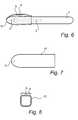
- FIG. 6is side view of one more embodiment of a pen according to the invention with inner parts indicated by dashed lines.
- FIG. 7is a side view of a removable cap according to an embodiment of the invention.
- FIG. 8is an end view of a removable cap provided with a clip having a hole for engagement with a pen point.
- an embodiment of a pen according to the inventioncomprising a pen body 1 , an ink cartridge arranged in the pen body and having a pen point 3 and a part, such as a clip 4 , which is removably arranged on the pen body 1 .
- the ink cartridge 2 and the pen point 3may form an ink stick which is exchangeable in its entirety.
- the pen point 3can be inserted into the ink cartridge 2 and define a distinguishable part, filling of the ink cartridge 2 being allowed after removal of the pen point 3 .
- the pen point 3 or the ink stick in its entiretycan be releasably arranged in the pen body 1 in various ways.
- ⁇may be arranged projecting from the inner wall of the pen body 1 and/or from the pen point/ink stick, and which may cooperate to cause locking or anchoring of the pen point or ink stick, which anchoring can be released under the action of a pulling force exerted on the pen point 3 .
- Such elementsmay comprise, for instance, flaps, beads etc.
- a common feature of the following exemplifying embodimentsis that they allow squeezing engagement with the pen point, so that the pen point can be extracted from the pen body, for instance for exchanging the ink stick or for filling the ink cartridge.
- the application of the pulling forcecan, via the squeezing engagement, be executed independently of the nature of the pen point. If the pen point has, for instance, an essentially smooth peripheral surface, the squeezing engagement may result in a frictional force which is sufficient to allow application of the pulling force. If the pen point instead has a profiled peripheral surface, the component or components applying squeezing forces may engage arbitrary protrusions, grooves, flaps etc. on the peripheral surface.
- the clipcan be provided with a hole in the form of a through hole.
- the clip and a protective caprespectively, can be provided with a hole in the form of a blind hole.
- blind holeis meant a non-through hole.
- the shown holes in the form of through holes and blind holesmay have a constant cross-section in depth. Alternatively, this cross-section may vary (not shown) over the depth of the hole. Thus, the hole can be tapering or widening in depth.
- the openings of a through holemay also be of different configurations, for instance different sizes or shapes.
- the squeezing engagementcan be performed by interaction between two parts, such as a holding part 7 and a counterflange 9 of the clip in FIG. 2B, or the cap 11 and the clip 4 in FIG. 8 .
- the means arranged on the movable part 4is a hole 5
- thisis formed so that it may be caused, by squeezing action, to engage the pen point 3 for extraction thereof.
- the hole 5is dimensioned, so that by exerting a force, for instance a frictional force, it may temporarily hold the pen point 3 to allow removal thereof from the pen body.
- the holemay have different shapes.
- a simple embodimentis shown in FIG. 3, where the hole is essentially circular.
- the holeis elongate and has wedge-shaped end portions.
- the holeis formed as a triangle, and in the embodiment according to FIG. 4C, the hole has the form of a “keyhole”.
- a hole 5 as described abovecan be used to remove the pen point 3 , and thus optionally the entire ink stick, from the pen body.
- the pen point 3is caused to engage in the hole 5 by inclination/angling of these two relative to each other.
- step Bthe pen point 3 is placed in the hole.
- step Cthe pen body is angled so that the pen point 3 is fastened in the hole 5 , and in step D the pen point/ink stick is extracted.
- the actions that are taken in step Care modifiable according to the appearance of function of the hole.
- the engagement between the clip and the pen pointmay be used to remove the latter by unscrewing it from the pen body.
- the clip 4may be formed as a separate elongate holding part 7 (FIG. 2 ), which at one end is attached to the pen body or a protective cap and which at its other end possibly has a bend 6 or bead which acts to better hold the pen in place when carried, for instance, in a user's pocket.
- the elongate holding part 7 of the clipmay be elongate, for instance rectangular, in cross-section, so that a flat side is formed, as is evident from FIGS. 3-5.
- the cliphas a fixing flange 8 , which makes an angle with the elongate holding part 7 of the clip.
- the anglemay be right, but other, larger or smaller, angles are feasible.
- the fixing flange 8can be releasably anchored to the pen body 1 at the rear end thereof, for instance by means of a screw, a locking pin, a snap connection, via a press fit or some other fixing means having an equivalent function.
- the fixing flange 8may correspondingly be releasably anchored in a groove extending transversely of the longitudinal direction of the pen, which groove may be formed in the pen body 1 or the protective cap 11 .
- the clip in FIG. 2Ahas a hole 5 in the fixing flange 8 , in the form of a through hole or a blind hole for the above engagement with the pen point 3 .
- the hole 5may be formed in the holding part 7 .
- a counterflange 9can be arranged, as shown in FIG. 2B, to extend under the bend 6 of the clip at a distance therefrom and be connected with the holding part 7 , possibly via a fixing flange 8 as described above.
- the pen pointis inserted into a variable gap 10 which is defined between the bend 6 of the clip and the counterflange 9 , the engagement being provided by pressing together the bend 6 of the clip and the counterflange 9 , like the jaws of a pair of pliers or the legs of a pair of tweezers.
- the bend 6 of the clipcan be formed in various ways, to provide a desired squeezing effect and to improve the holding of the pen when carried, for instance, in a pocket.
- a projectionmay be arranged adjacent to the gap, on the holding part 7 and/or on the counterflange 9 , the engagement being performed or facilitated by means of this projection, which may have, for instance, a sharp edge, a hole of a shape adapted to the general cross-section of pen points, etc.
- a variable gapmay be formed in the flat side of the clip.
- a hole of the type shown in FIG. 4Amay serve as such a gap, with a suitable selection of material and material thickness around the hole.
- the hole 5in the form of a blind hole in the clip, so formed that the pen point 3 can be caused to engage the boundary surfaces of the hole.
- the holemay have a cross-section varying in depth.
- FIG. 6one more embodiment of a pen according to the invention is shown, in which the part 4 , which is removably arranged on the pen body 1 , is a protective cap 11 with a clip 4 .
- This clipmay, like in the embodiments described with reference to FIGS. 1-4, has a hole 5 on its flat side in the form of one or more through holes or blind holes.
- Such a clipmay be formed in one piece with the protective cap 11 , or as a separate part.
- FIG. 7An alternative is shown in FIG. 7, viz. a cap 11 with an engaging hole 5 in its one, normally closed end.
- the hole 5can either be a blind hole or a through hole, and that the hole 5 can be arranged in an arbitrary position in the cap 11 .
- FIG. 8which shows one end of a cap with a clip 4 , seen from the open end of the cap, there may be formed according to a further alternative, on the underside of the clip 4 at its distal end, a projection with a hole 5 for engaging the pen point projecting from the pen body.
- the projectioncan be formed on the pen body to define said hole 5 .
- the pen pointcan be inserted into the hole 5 , after which the cap 11 and the pen body 1 are angled to each other to provide the engagement similarly to the above embodiments involving a through hole or a blind hole.
- a variable gapmay be formed between the clip 4 and the cap 11 , for instance at the distal end of the cap as illustrated in FIG. 8, or along the extent of the clip along the peripheral surface of the cap (cf. the space between the clip and the cap in the side view in FIG. 6 ).
- thisis inserted into the gap, from the short side or long side of the cap, after which the user can press the clip against the cap to provide the squeezing engagement with the pen point, like the jaws of a pair of pliers or the legs of a pair of tweezers.
- a projectioncan be formed adjacent to the gap, on the clip and/or on the cap, the engagement being provided or facilitated by means of this projection, which may have, for instance, a sharp edge, a hole of a shape adapted to the general cross-section of pen points, etc.
Landscapes
- Clips For Writing Implements (AREA)
Abstract
Description
Claims (16)
Priority Applications (1)
| Application Number | Priority Date | Filing Date | Title |
|---|---|---|---|
| US10/118,063US6719470B2 (en) | 2001-04-09 | 2002-04-09 | Pen |
Applications Claiming Priority (5)
| Application Number | Priority Date | Filing Date | Title |
|---|---|---|---|
| SE0101242 | 2001-04-09 | ||
| SE0101242-6 | 2001-04-09 | ||
| SE0101242ASE519436C2 (en) | 2001-04-09 | 2001-04-09 | Pen with detachable means arranged on the pen for replacement of ink pens provided in the pen, as well as a method for pin replacement |
| US28599601P | 2001-04-25 | 2001-04-25 | |
| US10/118,063US6719470B2 (en) | 2001-04-09 | 2002-04-09 | Pen |
Publications (2)
| Publication Number | Publication Date |
|---|---|
| US20030002911A1 US20030002911A1 (en) | 2003-01-02 |
| US6719470B2true US6719470B2 (en) | 2004-04-13 |
Family
ID=27354685
Family Applications (1)
| Application Number | Title | Priority Date | Filing Date |
|---|---|---|---|
| US10/118,063Expired - Fee RelatedUS6719470B2 (en) | 2001-04-09 | 2002-04-09 | Pen |
Country Status (1)
| Country | Link |
|---|---|
| US (1) | US6719470B2 (en) |
Cited By (25)
| Publication number | Priority date | Publication date | Assignee | Title |
|---|---|---|---|---|
| US20020107885A1 (en)* | 2001-02-01 | 2002-08-08 | Advanced Digital Systems, Inc. | System, computer program product, and method for capturing and processing form data |
| US20050013487A1 (en)* | 2001-01-24 | 2005-01-20 | Advanced Digital Systems, Inc. | System, computer software product and method for transmitting and processing handwritten data |
| US20060047539A1 (en)* | 2004-08-31 | 2006-03-02 | Paul Huang | Healthcare administration transaction method and system for the same |
| US20060085222A1 (en)* | 2004-10-14 | 2006-04-20 | Paul Huang | Healthcare administration transaction method and system for the same |
| US20060139338A1 (en)* | 2004-12-16 | 2006-06-29 | Robrecht Michael J | Transparent optical digitizer |
| US20060159345A1 (en)* | 2005-01-14 | 2006-07-20 | Advanced Digital Systems, Inc. | System and method for associating handwritten information with one or more objects |
| US20060233441A1 (en)* | 1999-03-31 | 2006-10-19 | Advanced Digital Systems, Inc. | System and method for editing handwritten data |
| US20060267965A1 (en)* | 2005-05-25 | 2006-11-30 | Advanced Digital Systems, Inc. | System and method for associating handwritten information with one or more objects via discontinuous regions of a printed pattern |
| US20070194127A1 (en)* | 1994-05-25 | 2007-08-23 | Rathus Spencer A | Method and apparatus for accessing electronic data via a familiar printed medium |
| USD594059S1 (en)* | 2007-09-27 | 2009-06-09 | Pentel Kabuskiki Kaisha | Ballpoint pen |
| US20110038659A1 (en)* | 2009-08-14 | 2011-02-17 | Andochick Scott E | Adjustable length pen holder |
| US8261994B2 (en) | 1994-05-25 | 2012-09-11 | Marshall Feature Recognition, Llc | Method and apparatus for accessing electronic data via a familiar printed medium |
| US8261993B2 (en) | 1994-05-25 | 2012-09-11 | Marshall Feature Recognition, Llc | Method and apparatus for accessing electronic data via a familiar printed medium |
| USD712473S1 (en) | 2012-09-10 | 2014-09-02 | Scott E. Andochick | Writing instrument holder |
| US8910876B2 (en) | 1994-05-25 | 2014-12-16 | Marshall Feature Recognition, Llc | Method and apparatus for accessing electronic data via a familiar printed medium |
| US10380920B2 (en) | 2013-09-23 | 2019-08-13 | SonoSim, Inc. | System and method for augmented ultrasound simulation using flexible touch sensitive surfaces |
| US11315439B2 (en) | 2013-11-21 | 2022-04-26 | SonoSim, Inc. | System and method for extended spectrum ultrasound training using animate and inanimate training objects |
| US11495142B2 (en) | 2019-01-30 | 2022-11-08 | The Regents Of The University Of California | Ultrasound trainer with internal optical tracking |
| US11600201B1 (en) | 2015-06-30 | 2023-03-07 | The Regents Of The University Of California | System and method for converting handheld diagnostic ultrasound systems into ultrasound training systems |
| US11627944B2 (en) | 2004-11-30 | 2023-04-18 | The Regents Of The University Of California | Ultrasound case builder system and method |
| US11631342B1 (en) | 2012-05-25 | 2023-04-18 | The Regents Of University Of California | Embedded motion sensing technology for integration within commercial ultrasound probes |
| US11749137B2 (en) | 2017-01-26 | 2023-09-05 | The Regents Of The University Of California | System and method for multisensory psychomotor skill training |
| US11810473B2 (en) | 2019-01-29 | 2023-11-07 | The Regents Of The University Of California | Optical surface tracking for medical simulation |
| US11938750B2 (en) | 2019-10-09 | 2024-03-26 | SOCIéTé BIC | Refillable free ink writing instrument provided with a removable tip |
| US12399923B1 (en) | 2023-09-15 | 2025-08-26 | Gabriele Nataneli | Multi-modal enhancement of large language models without retraining |
Families Citing this family (3)
| Publication number | Priority date | Publication date | Assignee | Title |
|---|---|---|---|---|
| USD543970S1 (en)* | 2005-09-23 | 2007-06-05 | Paul Griffin | Securement device attachable to an electronic device |
| US7845872B2 (en) | 2007-04-03 | 2010-12-07 | Family Hospitality Llc | Multi-colored crayons with associated packaging |
| JP2020187505A (en)* | 2019-05-14 | 2020-11-19 | 株式会社ワコム | Core remover |
Citations (14)
| Publication number | Priority date | Publication date | Assignee | Title |
|---|---|---|---|---|
| US454064A (en)* | 1891-06-16 | Pen-extractor | ||
| US3985457A (en) | 1974-07-26 | 1976-10-12 | Interlight | Writing implement having a replaceable refill |
| GB2001696A (en) | 1977-07-22 | 1979-02-07 | Italiana Lapis Affini Fab | A clip |
| US4892428A (en)* | 1986-11-27 | 1990-01-09 | J. S. Staedtler Gmbh & Co. | Tip removal device |
| US4952088A (en) | 1987-12-10 | 1990-08-28 | J.S. Staedtler Gmbh & Co. | Clip of caps adapted to remove shaft |
| US4981383A (en)* | 1986-11-04 | 1991-01-01 | J. S. Staedtler Gmbh & Co. | Device for screwing a writing instrument tip into a writing fluid reservoir |
| US5294792A (en) | 1991-12-31 | 1994-03-15 | Texas Instruments Incorporated | Writing tip position sensing and processing apparatus |
| EP0657301A1 (en) | 1993-12-07 | 1995-06-14 | Minnesota Mining And Manufacturing Company | Thermally transferable fluorine-containing azo dyes |
| EP0657306A1 (en) | 1993-12-07 | 1995-06-14 | PELIKAN GmbH | Refillable writing, painting or drawing instrument |
| US5434371A (en) | 1994-02-01 | 1995-07-18 | A.T. Cross Company | Hand-held electronic writing tool |
| US5852434A (en) | 1992-04-03 | 1998-12-22 | Sekendur; Oral F. | Absolute optical position determination |
| US6104388A (en) | 1997-07-18 | 2000-08-15 | Sharp Kabushiki Kaisha | Handwriting input device |
| US6130666A (en) | 1996-10-07 | 2000-10-10 | Persidsky; Andre | Self-contained pen computer with built-in display |
| WO2000073983A1 (en) | 1999-05-28 | 2000-12-07 | Anoto Ab | Position determination |
- 2002
- 2002-04-09USUS10/118,063patent/US6719470B2/ennot_activeExpired - Fee Related
Patent Citations (14)
| Publication number | Priority date | Publication date | Assignee | Title |
|---|---|---|---|---|
| US454064A (en)* | 1891-06-16 | Pen-extractor | ||
| US3985457A (en) | 1974-07-26 | 1976-10-12 | Interlight | Writing implement having a replaceable refill |
| GB2001696A (en) | 1977-07-22 | 1979-02-07 | Italiana Lapis Affini Fab | A clip |
| US4981383A (en)* | 1986-11-04 | 1991-01-01 | J. S. Staedtler Gmbh & Co. | Device for screwing a writing instrument tip into a writing fluid reservoir |
| US4892428A (en)* | 1986-11-27 | 1990-01-09 | J. S. Staedtler Gmbh & Co. | Tip removal device |
| US4952088A (en) | 1987-12-10 | 1990-08-28 | J.S. Staedtler Gmbh & Co. | Clip of caps adapted to remove shaft |
| US5294792A (en) | 1991-12-31 | 1994-03-15 | Texas Instruments Incorporated | Writing tip position sensing and processing apparatus |
| US5852434A (en) | 1992-04-03 | 1998-12-22 | Sekendur; Oral F. | Absolute optical position determination |
| EP0657301A1 (en) | 1993-12-07 | 1995-06-14 | Minnesota Mining And Manufacturing Company | Thermally transferable fluorine-containing azo dyes |
| EP0657306A1 (en) | 1993-12-07 | 1995-06-14 | PELIKAN GmbH | Refillable writing, painting or drawing instrument |
| US5434371A (en) | 1994-02-01 | 1995-07-18 | A.T. Cross Company | Hand-held electronic writing tool |
| US6130666A (en) | 1996-10-07 | 2000-10-10 | Persidsky; Andre | Self-contained pen computer with built-in display |
| US6104388A (en) | 1997-07-18 | 2000-08-15 | Sharp Kabushiki Kaisha | Handwriting input device |
| WO2000073983A1 (en) | 1999-05-28 | 2000-12-07 | Anoto Ab | Position determination |
Cited By (37)
| Publication number | Priority date | Publication date | Assignee | Title |
|---|---|---|---|---|
| US8910876B2 (en) | 1994-05-25 | 2014-12-16 | Marshall Feature Recognition, Llc | Method and apparatus for accessing electronic data via a familiar printed medium |
| US8485445B2 (en) | 1994-05-25 | 2013-07-16 | Marshall Feature Recognition, Llc | Method and apparatus for accessing electronic data via a familiar printed medium |
| US8261993B2 (en) | 1994-05-25 | 2012-09-11 | Marshall Feature Recognition, Llc | Method and apparatus for accessing electronic data via a familiar printed medium |
| US8261994B2 (en) | 1994-05-25 | 2012-09-11 | Marshall Feature Recognition, Llc | Method and apparatus for accessing electronic data via a familiar printed medium |
| US7717344B2 (en) | 1994-05-25 | 2010-05-18 | Marshall Feature Recognition, Llc | Method and apparatus for accessing electronic data via a familiar printed medium |
| US20070194127A1 (en)* | 1994-05-25 | 2007-08-23 | Rathus Spencer A | Method and apparatus for accessing electronic data via a familiar printed medium |
| US8115748B2 (en) | 1999-03-31 | 2012-02-14 | Ads Software Mgmt. L.L.C. | Electronically capturing handwritten data |
| US20060233441A1 (en)* | 1999-03-31 | 2006-10-19 | Advanced Digital Systems, Inc. | System and method for editing handwritten data |
| US7777729B2 (en) | 1999-03-31 | 2010-08-17 | Clary Gregory J | System and method for editing handwritten data |
| US20050013487A1 (en)* | 2001-01-24 | 2005-01-20 | Advanced Digital Systems, Inc. | System, computer software product and method for transmitting and processing handwritten data |
| US7869655B2 (en) | 2001-01-24 | 2011-01-11 | Ads Software Mgmt. L.L.C. | System, computer software product and method for transmitting and processing handwritten data |
| US7486824B2 (en) | 2001-01-24 | 2009-02-03 | Ads Software Mgmt. L.L.C. | System, computer software product and method for transmitting and processing handwritten data |
| US20090220162A1 (en)* | 2001-01-24 | 2009-09-03 | Ads Software Mgmt. L.L.C. | System, computer software product and method for transmitting and processing handwritten data |
| US20020107885A1 (en)* | 2001-02-01 | 2002-08-08 | Advanced Digital Systems, Inc. | System, computer program product, and method for capturing and processing form data |
| US20050093845A1 (en)* | 2001-02-01 | 2005-05-05 | Advanced Digital Systems, Inc. | System, computer program product, and method for capturing and processing form data |
| US20060047539A1 (en)* | 2004-08-31 | 2006-03-02 | Paul Huang | Healthcare administration transaction method and system for the same |
| US20060085222A1 (en)* | 2004-10-14 | 2006-04-20 | Paul Huang | Healthcare administration transaction method and system for the same |
| US11627944B2 (en) | 2004-11-30 | 2023-04-18 | The Regents Of The University Of California | Ultrasound case builder system and method |
| US20060139338A1 (en)* | 2004-12-16 | 2006-06-29 | Robrecht Michael J | Transparent optical digitizer |
| US7639876B2 (en) | 2005-01-14 | 2009-12-29 | Advanced Digital Systems, Inc. | System and method for associating handwritten information with one or more objects |
| US20060159345A1 (en)* | 2005-01-14 | 2006-07-20 | Advanced Digital Systems, Inc. | System and method for associating handwritten information with one or more objects |
| US7720286B2 (en) | 2005-05-25 | 2010-05-18 | Advanced Digital Systems, Inc. | System and method for associating handwritten information with one or more objects via discontinuous regions of a printed pattern |
| US20060267965A1 (en)* | 2005-05-25 | 2006-11-30 | Advanced Digital Systems, Inc. | System and method for associating handwritten information with one or more objects via discontinuous regions of a printed pattern |
| USD594059S1 (en)* | 2007-09-27 | 2009-06-09 | Pentel Kabuskiki Kaisha | Ballpoint pen |
| US20110038659A1 (en)* | 2009-08-14 | 2011-02-17 | Andochick Scott E | Adjustable length pen holder |
| US8408832B2 (en) | 2009-08-14 | 2013-04-02 | Scott E. Andochick | Adjustable length pen holder |
| US11631342B1 (en) | 2012-05-25 | 2023-04-18 | The Regents Of University Of California | Embedded motion sensing technology for integration within commercial ultrasound probes |
| USD712473S1 (en) | 2012-09-10 | 2014-09-02 | Scott E. Andochick | Writing instrument holder |
| US10380920B2 (en) | 2013-09-23 | 2019-08-13 | SonoSim, Inc. | System and method for augmented ultrasound simulation using flexible touch sensitive surfaces |
| US11315439B2 (en) | 2013-11-21 | 2022-04-26 | SonoSim, Inc. | System and method for extended spectrum ultrasound training using animate and inanimate training objects |
| US11594150B1 (en) | 2013-11-21 | 2023-02-28 | The Regents Of The University Of California | System and method for extended spectrum ultrasound training using animate and inanimate training objects |
| US11600201B1 (en) | 2015-06-30 | 2023-03-07 | The Regents Of The University Of California | System and method for converting handheld diagnostic ultrasound systems into ultrasound training systems |
| US11749137B2 (en) | 2017-01-26 | 2023-09-05 | The Regents Of The University Of California | System and method for multisensory psychomotor skill training |
| US11810473B2 (en) | 2019-01-29 | 2023-11-07 | The Regents Of The University Of California | Optical surface tracking for medical simulation |
| US11495142B2 (en) | 2019-01-30 | 2022-11-08 | The Regents Of The University Of California | Ultrasound trainer with internal optical tracking |
| US11938750B2 (en) | 2019-10-09 | 2024-03-26 | SOCIéTé BIC | Refillable free ink writing instrument provided with a removable tip |
| US12399923B1 (en) | 2023-09-15 | 2025-08-26 | Gabriele Nataneli | Multi-modal enhancement of large language models without retraining |
Also Published As
| Publication number | Publication date |
|---|---|
| US20030002911A1 (en) | 2003-01-02 |
Similar Documents
| Publication | Publication Date | Title |
|---|---|---|
| US6719470B2 (en) | Pen | |
| US6042078A (en) | Wall hanger, mounting kit, and method | |
| EP2055205A1 (en) | Bobby pin | |
| EP1379395B1 (en) | Pen with detachable means for extracting nib and method of extracting nib using said means | |
| US20040223800A1 (en) | Pen having cascaded cartridges of different colors | |
| US4243337A (en) | Fountain pen with ink refill carrier | |
| US11930906B2 (en) | Crafting scrap collection and nail polish holder devices and methods of use thereof | |
| US5967000A (en) | Plug remover for a bottle | |
| AU734987B2 (en) | Writing device and method for removing a writing core holder | |
| CN102421606B (en) | Applicator tool assembly and kit | |
| US5893672A (en) | Viscid substance recovery and dispenser device | |
| CN1809472B (en) | Drawing pin and drawing pin arrangement | |
| JPH0428797Y2 (en) | ||
| CN100589989C (en) | Small ball pen | |
| CN207639250U (en) | A kind of flowerpot with nameplate | |
| TWI333884B (en) | ||
| JP4615767B2 (en) | Optical plug attachment / detachment tool | |
| DE19707043C2 (en) | Centering device | |
| JP5465087B2 (en) | Endoscope hood attachment aid | |
| JP4471530B2 (en) | File binding tool fixing device | |
| JP3808305B2 (en) | Filing tools | |
| JP3040725U (en) | Photo album | |
| KR200284516Y1 (en) | Device for pushing in and pulling out a open eye needle in repairing a flat tire | |
| GB2294903A (en) | A binding for a pad of paper sheets comprising a deformable channel | |
| JPH11254890A (en) | Thumb tack having finger ring shaped tab |
Legal Events
| Date | Code | Title | Description |
|---|---|---|---|
| AS | Assignment | Owner name:ANOTO AB, SWEDEN Free format text:ASSIGNMENT OF ASSIGNORS INTEREST;ASSIGNOR:BERHIN, JOHAN;REEL/FRAME:012774/0525 Effective date:20020327 | |
| AS | Assignment | Owner name:ANOTO IP LIC HANDELSBOLAG, SWEDEN Free format text:ASSIGNMENT OF ASSIGNORS INTEREST;ASSIGNOR:ANOTO AB;REEL/FRAME:016386/0721 Effective date:20050225 Owner name:ANOTO IP LIC HANDELSBOLAG,SWEDEN Free format text:ASSIGNMENT OF ASSIGNORS INTEREST;ASSIGNOR:ANOTO AB;REEL/FRAME:016386/0721 Effective date:20050225 | |
| AS | Assignment | Owner name:ANOTO AKTIEBOLAG (ANOTO AB),SWEDEN Free format text:ASSIGNMENT OF ASSIGNORS INTEREST;ASSIGNOR:ANOTO IP LIC HANDELSBOLAG (ANOTO IP LIC HB);REEL/FRAME:017964/0148 Effective date:20060622 Owner name:ANOTO AKTIEBOLAG (ANOTO AB), SWEDEN Free format text:ASSIGNMENT OF ASSIGNORS INTEREST;ASSIGNOR:ANOTO IP LIC HANDELSBOLAG (ANOTO IP LIC HB);REEL/FRAME:017964/0148 Effective date:20060622 | |
| FEPP | Fee payment procedure | Free format text:PAYOR NUMBER ASSIGNED (ORIGINAL EVENT CODE: ASPN); ENTITY STATUS OF PATENT OWNER: LARGE ENTITY | |
| FPAY | Fee payment | Year of fee payment:4 | |
| FPAY | Fee payment | Year of fee payment:8 | |
| REMI | Maintenance fee reminder mailed | ||
| LAPS | Lapse for failure to pay maintenance fees | ||
| STCH | Information on status: patent discontinuation | Free format text:PATENT EXPIRED DUE TO NONPAYMENT OF MAINTENANCE FEES UNDER 37 CFR 1.362 | |
| FP | Lapsed due to failure to pay maintenance fee | Effective date:20160413 |