US6717922B2 - Network configuration protocol and method for rapid traffic recovery and loop avoidance in ring topologies - Google Patents
Network configuration protocol and method for rapid traffic recovery and loop avoidance in ring topologiesDownload PDFInfo
- Publication number
- US6717922B2 US6717922B2US10/090,669US9066902AUS6717922B2US 6717922 B2US6717922 B2US 6717922B2US 9066902 AUS9066902 AUS 9066902AUS 6717922 B2US6717922 B2US 6717922B2
- Authority
- US
- United States
- Prior art keywords
- ring
- port
- bridge
- master bridge
- control packets
- Prior art date
- Legal status (The legal status is an assumption and is not a legal conclusion. Google has not performed a legal analysis and makes no representation as to the accuracy of the status listed.)
- Expired - Fee Related, expires
Links
Images


Classifications
- H—ELECTRICITY
- H04—ELECTRIC COMMUNICATION TECHNIQUE
- H04L—TRANSMISSION OF DIGITAL INFORMATION, e.g. TELEGRAPHIC COMMUNICATION
- H04L45/00—Routing or path finding of packets in data switching networks
- H—ELECTRICITY
- H04—ELECTRIC COMMUNICATION TECHNIQUE
- H04L—TRANSMISSION OF DIGITAL INFORMATION, e.g. TELEGRAPHIC COMMUNICATION
- H04L12/00—Data switching networks
- H04L12/28—Data switching networks characterised by path configuration, e.g. LAN [Local Area Networks] or WAN [Wide Area Networks]
- H04L12/42—Loop networks
- H04L12/437—Ring fault isolation or reconfiguration
- H—ELECTRICITY
- H04—ELECTRIC COMMUNICATION TECHNIQUE
- H04L—TRANSMISSION OF DIGITAL INFORMATION, e.g. TELEGRAPHIC COMMUNICATION
- H04L45/00—Routing or path finding of packets in data switching networks
- H04L45/18—Loop-free operations
Definitions
- the invention disclosed hereinrelates to network configuration protocols and, in particular, to improved configuration protocols and methods for facilitating rapid traffic recovery following a link failure while still preventing loops from occurring in ring topologies.
- the spanning tree protocoldefined in IEEE 802.1, is used by bridges in a network to dynamically discover a subset of the network topology that provides path redundancy while preventing loops.
- Spanning tree protocolprovides redundancy by defining a single tree that spans the bridges and maintaining all other paths and connections in a standby or blocked state. The protocol allows bridges to transmit messages to one another that allow each bridge to select its place in the tree and which states should be applied to each of its ports to maintain that place.
- a port in a given bridge that is connected to an active path at a given timeis kept in a forwarding state, in which all data traffic is received and transmitted to the next portion of the network, and a port in the bridge that is connected to an inactive path is kept in a non-forwarding state such as a blocking state in which traffic is blocked through that port.
- bridges in a spanning tree networkpass bridge protocol data units, or BPDUs, to one another which contain information including root, bridge and port identifiers and path cost data. This information is used by the bridges, among other things, to “elect” one of the bridges in the spanning tree network to be a unique root bridge for the network, to calculate the shortest, least cost path from each bridge to the root bridge, to select which ports will be blocking, and for each LAN, elect one of the bridges residing in the LAN to be a designated bridge.
- BPDUsbridge protocol data units
- each bridgeinitially assuming itself to be the bridge, each bridge transmitting root BPDUs, each bridge comparing its BPDU information with that received from other bridges, and each bridge deciding whether to stop serving as a root and stop transmitting BPDUs when the configuration of another bridge as root is better than this bridge serving as root. Ports being converted from blocking to forwarding states and back again undergo several possible transition states depending upon the BPDUs received. Once the bridges have all reached their decisions, the network stabilizes or converges, and is eventually loop-free. A similar process is followed after a link failure has occurred in the network, in which case a new root and/or new active paths must be found.
- the spanning tree algorithmpresents several difficulties, particularly for large networks such as metropolitan area or wide area networks.
- the spanning tree protocolrequires each bridge to perform complex calculations and comparisons related to path costs, which requires substantial processing resources and time.
- convergence under the spanning tree algorithmdoes not occur until all bridges have exchanged messages and evaluated the path costs.
- spanning treehas a relatively high convergence time and requires the use of heavy computing resources.
- spanning treehas a seven bridge topology limitation.
- spanning tree protocolreduces performance in, and is not entirely adequate for use with, large networks such as MANs and WANs.
- the present inventionprovides a network configuration protocol and algorithm which resolves deficiencies with prior protocols.
- the present inventionrelies on the appreciation that a large network having many bridges may be built as a combination of smaller networks, many of which may each be arranged in a ring topology. Because ring topology configuration is predetermined, a shorter configuration control packet protocol may be used for each ring to manage redundancy and loop free operation.
- each ringmay be controlled by a single master bridge, selected for example by a system administrator, and each other bridge in the ring need not and does not make decisions with respect to its status. Finally, only the master bridge needs to change the status of its ports to effect redundancy.
- the use of computing resources in each ring and in the network as a wholeis kept to a minimum, and redundancy is provided with minimal looping and extremely rapid convergence times.
- a ring loop free topologyis achieved by means of selectively blocking and unblocking data traffic in one of the ring ports of a single master bridge for the ring. All other bridges in the ring keep their ports in non-blocked states.
- each ringhas a single master bridge which chooses one of its ports to be blocking.
- the master bridgequickly detects the failure and automatically changes its blocking port to a non-blocking state in which traffic may flow and follow an alternate path, avoiding the failed link.
- the master bridgequickly detects the link restoration and converts its port back to a blocking state to avoid a loop from occurring. Since each ring in the network governs its own link redundancy and loop avoidance, each ring may be connected to other rings or other network environments running other protocols, including spanning tree protocols or other proprietary protocols.
- the inventionprovides methodologies and data fields in the control packet protocol for coordinating control between connected rings.
- a shared linkformed between two shared bridges, e.g., bridges which have ports belonging to the two connected rings
- at least one of the ringscarries the control packets being forwarded around the other ring.
- the ring having the higher priority as between the two connected ringscarries the control packets of the lower priority ring.
- the control packetsare preferably marked as native to the lower priority ring, and thus foreign to the higher priority ring, before they are forwarded on to the higher priority ring.
- the two connected ringsform one large ring. Since the control packets for the lower priority ring are circulating around the entire ring, it does not detect the failure and thus keeps its blocking port from going into a forwarding state. Since the control packets for the higher priority ring do not circulate the entire larger ring, the master bridge for the higher priority ring detects the failure of the shared link and converts its blocking port to a forwarding state to provide fault recovery for the larger shared ring. In effect, the master bridge for the higher priority ring retains responsibility for providing fault recovery and loop free operation for the larger, combined ring.
- the inventionprovides a method for coordinating control of fault recovery between connected rings in a network, each ring being assigned a priority value different than priority values of other connected rings.
- the methodinvolves monitoring health of each ring through the use of control packets regularly transmitted and expected to be received by a master bridge of each ring, the master bridge converting one of its ports from a blocking state to a non-blocking state if a control packet is not received within an expected time delay from transmission.
- the methodfurther includes each ring forwarding control packets belonging to the ring and any other connected ring having lower priority than the ring.
- the methodincludes, if the shared link fails, forming a single ring from the two connected rings and the master bridge for the ring having the highest priority monitoring health of the formed single ring.
- a methodfor use in a network topology comprising a plurality of rings, each ring having a plurality of bridges each having a plurality of ports, two of which ports belong to the respective ring.
- One of the plurality of bridges in each ringserves as a master bridge for the ring, the master bridge having a first port belonging to the first ring which is convertible between a blocking state and a non-blocking and a second port being maintained in a non-blocking state. All ports for other bridges belonging to each ring other than the master bridge are maintained in non-blocking states.
- the inventive method according to this aspect of the inventionfacilitates rapid traffic recovery while avoiding loops, and involves regularly transmitting first control packets from a first master bridge onto a first ring, the first control packets each including a first ring identifier identifying the first ring, and regularly transmitting second control packets from a second master bridge onto a second ring, the second control packets each including a second ring identifier identifying the second ring.
- the one or more other bridges in the first ringforward the first control packets and, when available to the first ring, any second control packets.
- any first or second control packetis not received by the convertible blocking port for the first or second master bridge, respectively, within a set delay time from transmission of such first or second control packet, then the convertible port for the first or second master bridge, respectively, is converted from a blocking state to a non-blocking state. This opens that port up for traffic, thus compensating for a fault in the ring which occurred and caused the delay in receipt of the respective control packet.
- the master bridge convertible portreceives one or more subsequent first control packets while in a non-blocking state, and the number of subsequent first control packets received equals or exceeds a set threshold number, the master bridge convertible port is converted from a non-blocking state back to a blocking state.
- the set thresholdmay be one or may be more than one, in which case the master bridge counts the number of control packets received for comparison to the set threshold. This prevents a loop from forming when the failed link is restored, as determined by the timely receipt of the subsequent control packet.
- control packetsinclude a topology change flag.
- the first or second master bridgesets the topology change flag in at least one control packet transmitted following conversion of the first or second master bridge first port from a blocking state to a non-blocking state or from a non-blocking state to a blocking state.
- the other bridges in the first and second ringseach store bridging tables, and, upon receipt of a control packet having a set topology change flag, each of the other bridges flushes its stored bridging table.
- the non-blocking state discussed hereinmay include a forwarding state, in which all data traffic including control packets are processed and forwarded.
- a forwarding statein which all data traffic including control packets are processed and forwarded.
- an additional, intermediary non-blocking stateis provided in which data traffic continues to be blocked but control packets are processed and forwarded.
- This extra non-blocking statereferred to herein as a pre-forwarding state, allows for staged transitions from blocking to forwarding states while the master bridge determines more definitively whether it needs to go to a fully forwarding state.
- the pre-forwarding statealso allows for time while other events in the ring which may impact on the fault are resolved.
- the master bridge convertible portis converted from a pre-forwarding state to a forwarding state.
- At least one bridgeis a shared bridge having a shared port belonging to both the first and second rings.
- the first ringhas a higher priority than the second ring, and a port identifier is assigned to the shared port which matches the ring identifier for the first, higher priority ring.
- a second control packet received by a port in the shared bridge belonging to the second ringis marked, and, in each port of the shared bridge belonging to the second ring, a received marked control packet having a ring identifier which is the same as the port identifier of the port is de-marked.
- a received marked control packet having a ring identifier with a higher priority than the port identifieris dropped.
- the inventionincludes a computer readable medium storing a data structure defining a network configuration control packet protocol used by a ring topology in which each of a plurality of bridges has two ports belonging to a first ring.
- One of the bridges in the ringserves as a master bridge for the first ring, and a first master bridge port belonging to the first ring is maintained in a non-blocking state and a second master bridge port belonging to the first ring is convertible between a blocking state and one or more non-blocking states.
- the inventive control packet protocolincludes, among other data fields, a ring identifier representing a value of a ring to which the control packet applies, a foreign status flag representing whether the control packet is native to the first ring or belongs to a second ring in the network and is thus foreign to the first ring, and a topology change flag settable by the master bridge upon conversion of the state of the master bridge second port.
- the control packetis used by the master bridge, in accordance with methodologies described herein, to indicate whether a traffic link has failed or been restored in the ring, to determine whether to convert the second port from one state to another, and to notify non-master bridges in the ring of conversion of the second port.
- control packetfurther contains a master identifier representing the master bridge of the ring to which the control packet applies, a hello time field representing a time period in which the control packet is regularly sent by the master bridge, and a forwarding bit which is set by the master bridge to notify other bridges in the ring to go to a forwarding state from an intermediary or pre-forwarding state when, for example, the master bridge sets one of its ports to a blocking state.
- a networkin which each of a plurality of bridges has two ports belonging to a first ring.
- the networkcomprises a master bridge in which a first port belonging to the first ring is maintained in one or more non-blocking states and a second port is convertible between a blocking state and one or more non-blocking states.
- the master bridgecomprises transmission means for regularly transmitting first control packets onto the first ring, the control packets each including a ring identifier identifying the first ring.
- the networkfurther contains one or more non-master bridges in which both ports belonging to the first ring are maintained in non-blocking states, the non-master bridges forwarding first control packets and second control packets belonging to a second ring connected to the first ring.
- a program meansis provided in the master bridge for converting the convertible port from a blocking state to a non-blocking state if a first control packet is not received by the master bridge within a first delay time from transmission of such first control packet from the master bridge and for converting the convertible port from a non-blocking state to a blocking state if a first control packet is received by the second port within a second delay time from transmission of the first control packet from the master bridge first port.
- the networkcomprises means for distinguishing between first control packets belonging to the ring and second control packets belonging to the second ring.
- the means for distinguishing between first and second control packetsmay comprise a foreign status flag in the control packets which is set when a control packet belongs to the second ring, and may further include program code residing in the bridges in the first ring which, when executed, causes the bridges to detect the foreign status flag in each control packet and to determine whether each control packet belongs to the first or second ring.
- FIGS. 1A-1Care diagrams showing various exemplary ring topologies
- FIG. 2is a flow diagram showing the use of path blocking to avoid loops in a ring topology
- FIG. 3is a flow chart showing a process of providing fault recovery while avoiding loops in a ring topology, in accordance with one embodiment of the present invention
- FIG. 4is a diagram showing a loop-free ring network resulting from the use of the process of FIG. 3;
- FIG. 5is a transition diagram showing a loop-free fault recovery in the network shown in FIG. 4 through the use of the process of FIG. 3;
- FIG. 6is a transition diagram showing a restoration of the network shown in FIG. 4 through the use of the process of FIG. 3;
- FIG. 7is a state diagram showing transition between three port states in a master bridge in accordance with one embodiment of the present invention.
- FIG. 8is a state diagram showing transition between two port states in a non-master bridge in accordance with one embodiment of the present invention.
- FIG. 9is a data structure for a ring protocol data unit in accordance with one embodiment of the present invention.
- FIGS. 10-14are network diagrams illustrating various ring topologies in which a selection of a master bridge in each ring is required;
- FIG. 15is a network diagram showing several rings using the network configuration protocol of the present invention connected together and to other network configurations;
- FIG. 16is a network diagram illustrating shared bridges between two rings and the assignment of port identifiers in accordance with one embodiment of the present invention
- FIG. 17is a diagram of a shared bridge with port identifiers being assigned as regular or customer ports based on ring priority values;
- FIG. 18is a transition diagram illustrating the loop that arises when a shared link fails between a connected ring topology such as the one shown in FIG. 17;
- FIG. 19is a flow chart showing a process of sharing control packets between different connected rings in accordance with one embodiment of the present invention.
- FIG. 20is a transition diagram showing fault recovery in the connected ring topology of FIG. 17 when a shared link fails, in accordance with one embodiment of the present invention.
- FIG. 21is a transition diagram showing a restoration of the shared link between connected rings, in accordance with one embodiment of the present invention.
- a ring topologyis a network configuration formed when Layer 2 bridges are placed in a circular fashion with each bridge having two and only two ports belonging to a specific ring.
- FIGS. 1A-1Cshow different examples of ring topologies.
- FIG. 1Ashows a single ring 8 having bridges 10 connected by paths 12 .
- Each bridge in the ring 8 in FIG. 1Ahas two ports 10 a and 10 b belonging to the ring.
- FIG. 1Bshows two adjacent rings, 8 a and 8 b , with a single bridge 14 having two ports belonging to each ring.
- FIGS. 1 a and 1 bno links or bridges are shared among rings.
- two rings 8 c and 8 dare connected and share two bridges 16 .
- Each bridge 16has two ports 16 a and 16 b which are uniquely belong to only one ring, ring 8 c and 8 d respectively, and one port 16 c connected to a path which is shared by both rings.
- the ports 16 c connected to the shared linkassume the priority value of the higher priority ring, and ports (e.g., 16 a or 16 b ) in shared bridges 16 connected to the lower priority ring are deemed to be customer ports.
- FIGS. 1 a - 1 cpresent Layer 2 traffic looping problems.
- data trafficcan circulate around in either direction past their origination and thus create repetition of messages.
- one of the paths in the ringmust be blocked, as shown in FIG. 2.
- a ring loop free topologyis thus achieved by blocking data traffic in one of the ring ports.
- the portmay be declared to be in a blocking state, in which it does not learn or forward incoming or outgoing traffic.
- the portmust be convertible to a forwarding state in case of link failure.
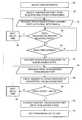
- a process for providing rapid fault recovery while preventing loops in a single ring topology (or in each ring in a multiple ring topology when the rings do not share ports)is now described with reference to FIG. 3 .
- the processbegins with the selection of one of the bridges in each ring to serve as the master bridge, step 30 .
- This selectionmay be made manually such as by a system administrator, or may be made through a partially or fully automated process.
- the selection of a bridge to be masterfollows a set of rules described below, and is not performed through a time and computing-resource consuming election process of the type used in the spanning tree algorithm to select a root bridge.
- One of the two ports in the master bridgeis initially chosen to be blocking, step 32 .
- the port chosen to be blockingis the port with fewer shared rings on the master bridge. All other bridges in the ring maintain their ports in one or more non-blocking states.
- the master bridgeis the only bridge which can selectively block all traffic and thus prevent a loop. This state is illustrated in FIG. 4, in which the master port 20 has one of its two ports 20 a in a forwarding state (designated as F) and the other port 20 b in a blocking state (designated as B).
- the master bridgeregularly transmits control packets, referred to herein for some embodiments as ring protocol data units or RPDUs, step 34 .
- the master bridgetransmits the RPDUs every hello seconds, regardless of other processing occurring in the master bridge such as the processing described below.
- the value of hello secondsmay be preset or may be set by a system administrator through a command line interface.
- the RPDUscontain, among other fields, a ring identifier which identifies the ring to which the RPDU applies. Every ring has an identifier assigned by the network administrator. This field is not strictly necessary for a single ring, but is useful in allowing rings to be connected and controlled separately, as explained in greater detail below.
- the blocking port on the master bridgeshould receive each RPDUs having the ring identifier within a set delay time. The blocking port thus awaits each RPDU, step 36 . The master bridge continues sending RPDUs after waiting hello seconds from transmission of the previous RPDU, steps 38 , 34 .
- step 40If a given RPDU for the ring is not received by the blocking port within the set delay time, sometimes referred to herein as dead_time seconds, step 40 , then the master bridge interprets this event as the occurrence of a link failure somewhere in the ring, and converts the blocking port to a non-blocking state, step 42 . This opens up this master bridge second port to traffic so that affected parts of the ring may receive data traffic. In some embodiments, the blocking port is converted immediately to a forwarding state.
- the blocking portis first converted to a pre-forwarding state, in which Layer 2 data traffic is blocked and Layer 2 addresses are not learned but RPDUs are received and processed, and then the port is converted to a forwarding state if RPDUs for the ring are still not received.
- a pre-forwarding stateallows more time for detection or resolution of the fault in the network before full data traffic is provided through the master bridge, and allows the chance for the master bridge to detect its RPDU and thus return to a blocking state and prevent a loop.
- a network administratormay set through a command line interface whether the port first converts to the pre-forwarding state before converting to the forwarding state.
- the ringIn the first portion, the ring is in a steady state, with one port forwarding and the other blocking. After a link failure 22 occurs in the ring, the blocking port 20 b fails to receive a RPDU within dead_time seconds, and the master bridge converts the port to a pre-forwarding state. After an additional time delay with still no RPDU being received, the port 20 b is then converted to a fully forwarding state, thus allowing traffic to travel to all bridges in the network via different pathways. If a control packet is received at the port 20 b while still in a pre-forwarding state, then the link has been restored and the port 20 b may be converted back to a blocking state before it goes to a forwarding state.
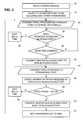
- the master bridgecontinues transmitting RPDUs every hello seconds from one another, step 44 , and the converted non-blocking port counts the number of RPDUs having the ring identifier it receives, step 46 . If the number of RPDUs received for the ring is not greater than a preset number, step 48 , this indicates that the link is still broken, and thus the port remains in its non-blocking state and further RPDUs continue to be transmitted every hello seconds from one another, steps 50 , 44 . If the number of RPDUs received within a given time frame is greater than a preset number, step 48 , this indicates that the link has been restored.
- the master bridgethen converts the port back to a blocking state, step 52 .
- This scenariois illustrated in the transition diagram in FIG. 6, in which the failed link 22 gets restored and the master bridge converts the port 20 b back to a blocking state B.
- the master bridgealso sets a forwarding flag or bit in the RPDU, step 54 , to notify other bridges in the ring that they may transition from a pre-forwarding state to a forwarding state.
- one of the master bridge portstransitions between three states—blocking, pre-forwarding, and forwarding.
- the conditions under which the port undergoes these transitionsis summarized in the state diagram in FIG. 7 .
- Non-master bridge portsdo not become blocking, but assume one of the two non-blocking states, pre-forwarding or forwarding. These states and their transitions are shown in the state diagram in FIG. 8 .
- the RPDUcontains a forwarding flag set by the master bridge such as, for example as explained above, when the master bridge converts its convertible port from a non-blocking to a blocking state.
- the bridgeWhen each non-master port receives a RPDU passing through with the forwarding flag set, the bridge declares the port to be forwarding. If no RPDU with a forwarding flag set is seen by the port for pf_delay time, the port is declared by the bridge to be forwarding. These transitions are shown in FIG. 8 .
- the data structure for one embodiment of the RPDU control packetis shown in FIG. 9 .
- This RPDU structurefollows a 802.3 packet format, with the source MAC address being the master bridge's MAC address.
- the packetincludes a protocol identifier field, default value of one, and a protocol version field, default value 0 .
- the packetcontains three flags: a topology change (tc) flag, set by the master bridge whenever it converts its port between states; a forwarding flag, set by the master bridge to instruct the other bridges to take their ports to forwarding states; and a foreign status flag set by ports to indicate that a control packet has been marked as belonging, or native, to a specific ring even though it will be forwarded to another ring or rings, and is foreign to the other rings, as described in greater detail below.
- tctopology change
- the control packetfurther includes: a VLAN identifier which takes the value of the master VLAN in a ring VLAN group; a ring identifier, as discussed above, which is assigned the value of the ring to which the packet applies; and a master identifier which represents the identification of the master, which may be the MAC address for the master bridge.
- a sequence number fieldallows expansion of the protocol, and a hello time field is set by the master as the period in which the master transmits the hello packets, as represented in ⁇ fraction (1/256) ⁇ portions of a second.
- the master bridgeWhen a master bridge port changes from forwarding to blocking state or from blocking to forwarding, the master bridge sets the Topology Change flag in the RPDUs that it is generating. When bridges in the ring receive a RPDU with Topology Change set, they flush their bridging tables. Upon receiving the TC RPDU back, the master bridge sets the flag to be zero, thus deactivating it, since the other bridges in the ring have now adjusted to the topology change.
- the master bridgeWhen a master bridge port goes from pre-forwarding to forwarding, and therefore the ring gets partitioned (see FIG. 5 ), the master bridge generates RPDUs with TC flag set in both directions of the ring. Since some bridges may not receive the RPDU and thus may not see the TC flag, the master bridge sends the RPDUs with the TC flag set multiple times, e.g., three times. A bridge that has already adjusted to a topology change by flushing its bridging tables as described above which subsequently receives another RPDU with the TC flag set does not flush the other two times it sees the TC flag set.
- one bridgeis selected as master for each ring.
- This selectionis performed in accordance with a set of rules, and may be performed manually by the administrator, by the administrator after a software program has excluded certain choices based on the rules, or automatically by a software program which applies the rules to limit the choices and selects one of the remaining viable choices.
- the rulesare: first, that the master is a bridge that does not have multiple rings configured on its ports; second, that if this is not possible, the master for a particular ring cannot be customer ports, that is, ports that do not belong to the highest priority ring between two or more connected rings, as described further below; and third, that if this is not possible, then ring priorities must be adjusted to allow application of the second rule.
- FIGS. 10-14illustrate various network configurations useful in illustrating applications of these rules.
- all bridgesmay be masters for their ring. This includes Bridge A, which may be a master for ring 1 or ring 2 since it has no ports shared between ring 1 and ring 2 .
- all bridges in ring 1may be master, including bridges A and B, which have two ports for ring 1 . However, bridges A and B may not serve as masters for ring 2 because they do not have two non-customer ports with ring identifier 2 .
- all bridges on ring 1may be chosen as master.
- Ring twomay not choose bridges A and D as masters since they do not have two non-customer ports, but may choose bridge B as master since bridge B has to non-customer ports.
- Ring threemay not choose bridges B, C, or D, but may choose any other bridge as its master.
- rings 1 and 2may choose any bridge as master, since all bridges in those rings have two non-customer ports, but ring 3 may not choose any of the four bridges to which it is connected since none has two non-customer ports since ring 3 has the lowest priority.
- the topologies in FIG. 13must be rearranged as shown in FIG. 14 so that the ring with the lowest priority is not the intermediate ring, which allows ring 3 to have at least one, in this case two, bridges to select as master.
- rings utilizing the inventive protocol described hereinmay be combined around a larger metro-ring and with other Layer 2 protocols such as spanning tree protocol (STP) networks.
- STPspanning tree protocol
- a metro-ringmay be combined at some of its bridges with another network through the Superspan domain available from Foundry Networks of San Jose, Calif., the assignee of the present application. In these combinations, the metro-ring protocol just applies to ports belonging to each specific ring.
- Each ringis assigned a ring identifier.
- Ring identifiersmay be ranked according to priority, with, in one embodiment, the priorities being inversely related to the ring identifier value. That is, the lower the ring identifier, the higher the priority.
- the ring identifieris used to identify all ports belonging to the ring.
- each portgets assigned a single port identifier. If the port is not shared between rings, the port identifier is the same as the ring identifier for the ring to which the port belongs. If the port is shared among different rings, the port is assigned the identifier of the higher or highest priority ring.
- FIG. 16An example of port identifier assignments is shown in FIG. 16 .
- the ports connected to the path 100 between shared bridges 102 , 104are assigned the port identifier 1 , matching ring 1 , since ring 1 has a higher priority than ring 2 .
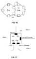
- FIG. 17illustrates a bridge 106 having four ports 106 a , 106 b , 106 c , 106 d connected to rings. Ports 106 a and 106 b are connected to ring 1 , and thus assume the highest priority. Ports 106 c and 106 d are assigned to lower priority rings, ring 2 and ring 3 , respectively, and are thus declared to be customer ports.
- each of two connected ringswere to have a master bridge which independently decided whether to open a convertible port to a forwarding state in case of a link failure, then the result of a shared link failure is a single larger ring in a loop.
- FIG. 18This scenario is shown in FIG. 18 .
- each of rings 1 and 2circulates RPDUs only within its own ring.
- both master bridgesmaster bridge 106 for ring 1 and master bridge 108 for ring 2 , fail to receive their respective RPDUs and determine that a link failure has occurred. Both master bridges then independently transition their blocking ports to a non-blocking state, e.g., first to a pre-forwarding state and then to a forwarding state, in order to effectuate fault recovery.
- a non-blocking statee.g., first to a pre-forwarding state and then to a forwarding state, in order to effectuate fault recovery.
- the resultas shown in the right hand side of FIG. 18, is a single loop formed by the combination of the two previously separate rings, with all ports in a forwarding state, including both ports in each master bridge 106 , 108 . As can be readily seen, this results in an undesirable looping situation.
- each bridgeis therefore programmed with software to follow a set of rules designed to keep RPDU messages separate but available to the proper rings in a connected network topology.
- the followingare the rules that ring ports follow in one embodiment regarding RPDU transmission if they are in forwarding or pre-forwarding state. In blocking state the ports drop all RPDUs.
- the rules for port behaviorare summarized in Table I, provided below, and in FIG. 19 .
- Rule 1A customer port marks incoming RPDUs as native to its ring by setting the foreign status flag, and changes the RPDU MAC address.
- Rule 2A customer port de-marks marked RPDUs (by resetting the foreign status flag to null) if the marked RPDU has the same ring identifier as the port identifier.
- Rule 3A ring port drops all marked RPDUs with higher priority than the port identifier itself.
- a bridgeUpon receiving a marked RPDU, a bridge checks if any if its ports is a customer port for that RPDU. If yes, the bridge de-marks the RPDU and sends it in the customer port. In any other case, it broadcasts the marked RPDU in all the ports that have an identifier with higher priority than the RPDU (following Rule 3).
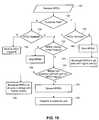
- step 120the port runs a different subroutine depending upon whether it is a customer port or not, step 122 .
- the portchecks whether the RPDU is marked by having the foreign status flag set, step 124 . If the flag is not set, the RPDU is transmitted to the other ring ports, step 126 . Thus, regular ports simply forward on regular RPDUs. If the RPDU is marked, then the port determines whether the RPDU ring identifier has a higher or equal priority than the priority of the port identifier, step 128 .
- the portdrops the RPDU, step 130 , since lower priority rings do not carry RPDUs for higher priority rings. If the RPDU has higher priority than the port, then the bridge determines whether it has a customer port with a port identifier the same as the RPDU ring identifier, step 132 . If such a customer port exists in the bridge, the RPDU is de-marked, step 134 , and transmitted to the customer port, step 136 . Thus, the RPDU is then transmittable back onto its proper ring without any marking, that is, as a foreign control packet.
- the RPDUis broadcast on all ports in the bridge having higher priority than the RPDU, step 138 .
- the RPDUcontinues to be marked with the foreign status flag, so that the higher priority rings are aware that this RPDU belongs to a different, lower priority ring and must be forwarded to prevent the looping situation outlined above.
- the portruns a subroutine to determine first whether the RPDU is marked, step 140 . If not, the customer port marks the RPDU by setting its foreign status flag, step 142 , and broadcasts the marked RPDU in all ports in the bridge having higher priority than the RPDU ring identifier, step 144 . If the RPDU is marked, then the port checks whether the RPDU priority is higher than or equal to the port priority, step 128 . The process continues as explained above with reference to regular ports.
- FIGS. 20-21Fault recovery and loop prevention in connected rings is shown in FIGS. 20-21.
- both master bridge 106 for ring 1 and master bridge 108 for ring 2encounter delays in receiving their RPDUs, and thus convert their convertible ports from blocking states to pre-forwarding states, in accordance with the processes described above.
- ring 1the higher priority ring
- the RPDUs for ring 2eventually arrive at the master bridge 108 for ring 2 .
- the ring 2 master bridge 108converts the convertible port back from its pre-forwarding state to a blocking state.
- the master bridge 106 for ring 1still does not receive its RPDUs, since they are not carried in ring 2 bridges, and thus the master bridge converts its convertible port to a forwarding state.
- the final stateas shown on the right in FIG. 20, is a single ring with one master bridge having gone fully forwarding and the other with one port still blocked, thus providing fault recovery and no looping.
- the link restoration scenariois illustrated in FIG. 21 .
- ring 1 RPDUsare again circulating and are then received by the ring 1 master bridge 106 .
- That master bridge 106then converts its convertible port back to a blocking state, avoiding looping.
Landscapes
- Engineering & Computer Science (AREA)
- Computer Networks & Wireless Communication (AREA)
- Signal Processing (AREA)
- Small-Scale Networks (AREA)
Abstract
Description
| TABLE I | |||
| RPDU | RPDU priority ≧ | ||
| type | Port Type | Port priority | action |
| Regular | Regular | N/A | Send RPDU to other ring port |
| Regular | Customer | N/A | Mark RPDU with port identifier |
| and broadcast in all ports with | |||
| higher priority | |||
| Marked | Regular | NO | Drop RPDU |
| Marked | X | YES | If bridge has a customer port for |
| RPDU ring identifier, de-mark | |||
| RPDU and send it on that port. | |||
| If bridge has no customer port | |||
| for the RPDU ring identifier, | |||
| broadcast marked RPDU on | |||
| all ports with higher priority. | |||
| Marked | Customer | NO | Drop RPDU |
Claims (25)
Priority Applications (3)
| Application Number | Priority Date | Filing Date | Title |
|---|---|---|---|
| US10/090,669US6717922B2 (en) | 2002-03-04 | 2002-03-04 | Network configuration protocol and method for rapid traffic recovery and loop avoidance in ring topologies |
| AU2003213703AAU2003213703A1 (en) | 2002-03-04 | 2003-03-03 | Network configuration protocol and method for rapid traffic recovery and loop avoidance in ring topologies |
| PCT/US2003/006550WO2003077459A2 (en) | 2002-03-04 | 2003-03-03 | Network configuration protocol and method for rapid traffic recovery and loop avoidance in ring topologies |
Applications Claiming Priority (1)
| Application Number | Priority Date | Filing Date | Title |
|---|---|---|---|
| US10/090,669US6717922B2 (en) | 2002-03-04 | 2002-03-04 | Network configuration protocol and method for rapid traffic recovery and loop avoidance in ring topologies |
Publications (2)
| Publication Number | Publication Date |
|---|---|
| US20030165119A1 US20030165119A1 (en) | 2003-09-04 |
| US6717922B2true US6717922B2 (en) | 2004-04-06 |
Family
ID=27804059
Family Applications (1)
| Application Number | Title | Priority Date | Filing Date |
|---|---|---|---|
| US10/090,669Expired - Fee RelatedUS6717922B2 (en) | 2002-03-04 | 2002-03-04 | Network configuration protocol and method for rapid traffic recovery and loop avoidance in ring topologies |
Country Status (3)
| Country | Link |
|---|---|
| US (1) | US6717922B2 (en) |
| AU (1) | AU2003213703A1 (en) |
| WO (1) | WO2003077459A2 (en) |
Cited By (46)
| Publication number | Priority date | Publication date | Assignee | Title |
|---|---|---|---|---|
| US20010025318A1 (en)* | 2000-03-17 | 2001-09-27 | Anritsu Corporation | Apparatus and method for configuring spanning tree and spanning tree protocol system and bridge system |
| US20040223503A1 (en)* | 2003-05-06 | 2004-11-11 | Overture Networks, Inc. | Protected switching ring |
| US20050013260A1 (en)* | 2003-06-09 | 2005-01-20 | Foundry Networks, Inc. | System and method for multiple spanning tree protocol domains in a virtual local area network |
| US20050125501A1 (en)* | 2003-12-05 | 2005-06-09 | Kazuyuki Inomoto | Method and apparatus for setting master node of ring network |
| US20050201409A1 (en)* | 2003-05-06 | 2005-09-15 | Overture Networks, Inc. | Apparatus and method for rapid detection of unidirectional breaks in a network ring |
| US20050243823A1 (en)* | 2003-05-06 | 2005-11-03 | Overture Networks, Inc. | Multipoint protected switching ring |
| US20060007869A1 (en)* | 2004-07-09 | 2006-01-12 | Fujitsu Limited | Method for preventing control packet loop and bridge apparatus using the method |
| US20060165002A1 (en)* | 2004-11-01 | 2006-07-27 | Timothy Hicks | Port re-enabling by monitoring link status |
| US20070047472A1 (en)* | 2005-08-30 | 2007-03-01 | Lionel Florit | System and method for implementing multiple ring networks using a common link |
| WO2006065795A3 (en)* | 2004-12-14 | 2007-03-15 | Alcatel Lucent | Ring rapid spanning tree protocol |
| US20070070974A1 (en)* | 2005-09-29 | 2007-03-29 | Mo Rooholamini | Event delivery in switched fabric networks |
| US7209435B1 (en) | 2002-04-16 | 2007-04-24 | Foundry Networks, Inc. | System and method for providing network route redundancy across Layer 2 devices |
| US20070237072A1 (en)* | 2006-04-07 | 2007-10-11 | Sbc Knowledge Ventures, L.P. | Resilient ip ring protocol and architecture |
| US20070253330A1 (en)* | 2005-01-07 | 2007-11-01 | Yuji Tochio | Node setting apparatus, network system, node setting method, and computer product |
| US20080025203A1 (en)* | 2006-07-25 | 2008-01-31 | Francois Tallet | Alternate spanning tree for faster indirect link failure recovery |
| US20080095047A1 (en)* | 2006-06-29 | 2008-04-24 | Nortel Networks Limited | Method and system for looping back traffic in qiq ethernet rings and 1:1 protected pbt trunks |
| US20080123562A1 (en)* | 2006-08-15 | 2008-05-29 | Lionel Florit | System and method for integrating ring-protocol-compatible devices into network configurations that also include non-ring-protocol compatible devices |
| US20080205302A1 (en)* | 2007-02-27 | 2008-08-28 | Lionel Florit | Preventing data traffic connectivity between endpoints of a network segment |
| US20080275999A1 (en)* | 2007-05-01 | 2008-11-06 | Brother Kogyo Kabushiki Kaisha | Information distribution system, terminal apparatus used in such system, recording medium on which program is recorded, and loop connection avoidance method |
| US20080298371A1 (en)* | 2007-05-30 | 2008-12-04 | Yoshiharu Kobatake | Relay apparatus capable of preventing mistaken learning of mac address learning table |
| US7545735B1 (en)* | 2003-03-11 | 2009-06-09 | Atrica Israel Ltd. | Scalable protection mechanism for hierarchical multicast service in ring based networks |
| US7558205B1 (en) | 2003-08-01 | 2009-07-07 | Foundry Networks, Inc. | System and method for detecting and isolating a remote loop |
| US7564858B1 (en)* | 2003-08-01 | 2009-07-21 | Foundry Networks, Inc. | System and method for enabling a remote instance of a loop avoidance protocol |
| US7606240B1 (en) | 2005-06-16 | 2009-10-20 | Extreme Networks | Ethernet automatic protection switching |
| US20090262643A1 (en)* | 2008-04-16 | 2009-10-22 | Hangzhou H3C Technologies Co., Ltd. | Method for implementing intersecting ring network with arbitrary topology, node and intersecting ring network |
| US20090268609A1 (en)* | 2008-04-25 | 2009-10-29 | Calix, Inc. | Efficient management of ring networks |
| US20090274153A1 (en)* | 2002-10-01 | 2009-11-05 | Andrew Tai-Chin Kuo | System and method for implementation of layer 2 redundancy protocols across multiple networks |
| US20090323517A1 (en)* | 2008-06-26 | 2009-12-31 | Shore Microsystems Inc. | Autolearning network link protection device |
| US7672228B1 (en)* | 2003-03-19 | 2010-03-02 | Extreme Networks, Inc. | System and method for network loop detection and recovery |
| US7680031B1 (en)* | 2002-04-26 | 2010-03-16 | Redback Networks Inc. | Method and apparatus for load balancing and protecting data traffic in an optical ring |
| US20100238813A1 (en)* | 2006-06-29 | 2010-09-23 | Nortel Networks Limited | Q-in-Q Ethernet rings |
| US20100309821A1 (en)* | 2009-06-04 | 2010-12-09 | Eci Telecom, Ltd. | Method and network for combined protection of ethernet traffic |
| US20110292833A1 (en)* | 2009-01-30 | 2011-12-01 | Kapitany Gabor | Port table flushing in ethernet networks |
| US20120155484A1 (en)* | 2009-08-20 | 2012-06-21 | Sergeev Andrew | Technique for dual homing interconnection between communication networks |
| US20130170337A1 (en)* | 2011-12-29 | 2013-07-04 | Vijay Vallala | Verifying Communication Redundancy in a Network |
| US20130194972A1 (en)* | 2007-08-14 | 2013-08-01 | Torsten Mueller | Network Reconfiguration Method |
| US8520507B1 (en) | 2004-03-08 | 2013-08-27 | Extreme Networks, Inc. | Ethernet automatic protection switching |
| US20140025985A1 (en)* | 2012-07-18 | 2014-01-23 | Fujitsu Limited | Communication control device and communication control method |
| US8654630B2 (en) | 2010-03-19 | 2014-02-18 | Brocade Communications Systems, Inc. | Techniques for link redundancy in layer 2 networks |
| US8792333B2 (en)* | 2012-04-20 | 2014-07-29 | Cisco Technology, Inc. | Failover procedure for networks |
| US9148346B2 (en) | 2012-09-05 | 2015-09-29 | Brocade Communications Systems, Inc. | Multiple ring identification and configuration protocol |
| US9338060B2 (en) | 2012-09-05 | 2016-05-10 | Brocade Communications Systems, Inc. | Multiple ring identification and configuration protocol |
| US9444641B2 (en) | 2012-09-05 | 2016-09-13 | Brocade Communications Systems, Inc. | MAC flush optimizations for ethernet rings |
| US10142015B2 (en) | 2015-02-16 | 2018-11-27 | Alibaba Group Holding Limited | Method and apparatus for detecting shared risk link groups |
| US10243969B2 (en) | 2015-09-23 | 2019-03-26 | Alibaba Group Holding Limited | Method and system for identifying network loops |
| US20220272006A1 (en)* | 2021-02-24 | 2022-08-25 | Cisco Technology, Inc. | Lightweight ring manager with distributed policies |
Families Citing this family (67)
| Publication number | Priority date | Publication date | Assignee | Title |
|---|---|---|---|---|
| US6965560B2 (en)* | 2002-07-10 | 2005-11-15 | I/O Controls Corporation | Multi-tier, hierarchical fiber optic control network |
| US6961306B2 (en)* | 2002-07-10 | 2005-11-01 | I/O Controls Corporation | Fiber optic control network and related method |
| US7046621B2 (en)* | 2002-07-10 | 2006-05-16 | I/O Controls Corporation | Redundant multi-fiber optical ring network |
| US7532588B2 (en)* | 2003-02-19 | 2009-05-12 | Nec Corporation | Network system, spanning tree configuration method and configuration program, and spanning tree configuration node |
| US9451422B2 (en)* | 2003-03-17 | 2016-09-20 | Nokia Technologies Oy | Method, system and network device for routing a message to a temporarily unavailable network user |
| US7602706B1 (en)* | 2003-05-15 | 2009-10-13 | Cisco Technology, Inc. | Inter-ring protection for shared packet rings |
| US7339900B2 (en)* | 2003-09-26 | 2008-03-04 | Sun Microsystem, Inc. | Method and apparatus for preventing spanning tree loops during traffic overload conditions |
| US7675869B1 (en)* | 2004-07-06 | 2010-03-09 | Marvell International Limited | Apparatus and method for master election and topology discovery in an Ethernet network |
| GB2421669A (en)* | 2004-12-22 | 2006-06-28 | Siemens Ag | Method for restoring a link in a communication ring system |
| EP1854250B1 (en)* | 2005-02-28 | 2011-09-21 | International Business Machines Corporation | Blade server system with at least one rack-switch having multiple switches interconnected and configured for management and operation as a single virtual switch |
| JP4627205B2 (en)* | 2005-03-28 | 2011-02-09 | 富士通株式会社 | Ring network system and failure recovery method |
| CN100370753C (en)* | 2005-04-04 | 2008-02-20 | 华为技术有限公司 | The Method of Preventing User Side Ring Network on Digital Subscriber Line Concentrator |
| US8050183B2 (en) | 2005-05-06 | 2011-11-01 | Cisco Technology, Inc. | System and method for implementing reflector ports within hierarchical networks |
| EP1727313A1 (en)* | 2005-05-25 | 2006-11-29 | Siemens Aktiengesellschaft | Ring network and method for automatic protection switching |
| PT1729453E (en)* | 2005-05-31 | 2008-11-03 | Nokia Siemens Networks Gmbh | Method for protection switching |
| US8325629B2 (en) | 2005-07-15 | 2012-12-04 | Cisco Technology, Inc. | System and method for assuring the operation of network devices in bridged networks |
| CA2616409C (en)* | 2005-08-08 | 2015-06-16 | Tino Zottola | Shared dsl network and deployment method |
| US8139476B2 (en)* | 2005-10-13 | 2012-03-20 | Vello Systems, Inc. | Optical ring networks using circulating optical probe in protection switching with automatic reversion |
| US7590120B2 (en)* | 2005-11-18 | 2009-09-15 | Cisco Technology, Inc. | Enhanced multicast VLAN registration |
| US7911938B2 (en) | 2006-01-20 | 2011-03-22 | Cisco Technology, Inc. | System and method for preventing loops in the presence of control plane failures |
| US7796532B2 (en)* | 2006-05-31 | 2010-09-14 | Cisco Technology, Inc. | Media segment monitoring |
| CN101141366A (en)* | 2006-09-07 | 2008-03-12 | 华为技术有限公司 | A Method to Avoid Data Loops in Ring Ethernet |
| WO2008037781A1 (en)* | 2006-09-29 | 2008-04-03 | Nokia Siemens Networks Gmbh & Co. Kg | Method for protection switching in ring topologies |
| WO2008056088A2 (en) | 2006-11-10 | 2008-05-15 | Thomson Licensing | Method for restoring a service booking system in a network after failure |
| US7814248B2 (en)* | 2006-12-07 | 2010-10-12 | Integrated Device Technology, Inc. | Common access ring/sub-ring system |
| US7809871B2 (en)* | 2006-12-07 | 2010-10-05 | Integrated Device Technology Inc. | Common access ring system |
| CN101232428B (en) | 2007-01-23 | 2012-05-23 | 华为技术有限公司 | Method and device for protecting an Ethernet ring |
| CN101232427A (en) | 2007-01-23 | 2008-07-30 | 华为技术有限公司 | Ethernet loop protection method and apparatus |
| US8520508B2 (en)* | 2007-02-13 | 2013-08-27 | Force10 Networks, Inc. | Spanning tree ring protocol |
| US8175458B2 (en) | 2007-07-17 | 2012-05-08 | Vello Systems, Inc. | Optical ring networks having node-to-node optical communication channels for carrying data traffic |
| JP4874185B2 (en) | 2007-07-19 | 2012-02-15 | アラクサラネットワークス株式会社 | Multi-fault handling system and shared link terminator used therefor |
| DE602007009669D1 (en)* | 2007-08-06 | 2010-11-18 | Nokia Siemens Networks Oy | Method and apparatus for operating a network and communication system with such a device |
| CN101127675A (en)* | 2007-09-25 | 2008-02-20 | 中兴通讯股份有限公司 | Master node initialization method of Ethernet ring network system |
| CN101127674B (en)* | 2007-09-25 | 2011-11-30 | 中兴通讯股份有限公司 | Initialization method for transmission nodes of Ethernet loop network system |
| CA2620490C (en) | 2007-10-04 | 2016-06-28 | Genesis Technical Systems Corp. | Remote powering of dsl adms |
| US7801028B2 (en)* | 2007-12-31 | 2010-09-21 | Schneider Automation Inc. | Method and apparatus for transparent auto-recovery in chain and ring networks |
| US7944815B2 (en)* | 2008-02-14 | 2011-05-17 | Allied Telesis Holdings K.K. | System and method for network recovery from multiple link failures |
| JP2009206891A (en)* | 2008-02-28 | 2009-09-10 | Nec Corp | Layer 2 ring network system and management method therefor |
| CN101534232B (en)* | 2008-03-10 | 2012-12-19 | 中兴通讯股份有限公司 | Method for preventing internet storm occurring in Ether multi-ring network |
| US8107383B2 (en) | 2008-04-04 | 2012-01-31 | Extreme Networks, Inc. | Reducing traffic loss in an EAPS system |
| US7856019B2 (en) | 2008-08-29 | 2010-12-21 | Extreme Networks, Inc. | Convergence of multicast traffic |
| CN101686158B (en)* | 2008-09-22 | 2012-11-14 | 中兴通讯股份有限公司 | Control method for Ethernet loop guard fault recovery and Ethernet loop node |
| CN101741670B (en)* | 2008-11-27 | 2012-12-19 | 中兴通讯股份有限公司 | Method for protecting multi-ring Ethernet |
| WO2010066300A1 (en)* | 2008-12-11 | 2010-06-17 | Telefonaktiebolaget Lm Ericsson (Publ) | Communications network |
| TW201042953A (en)* | 2009-05-21 | 2010-12-01 | Moxa Inc | Processing method of redundancy check for chain network |
| CN101562552B (en)* | 2009-05-27 | 2011-09-14 | 华为技术有限公司 | Method, system and device for detecting virtual private LAN loop |
| CN101997735A (en)* | 2009-08-25 | 2011-03-30 | 中兴通讯股份有限公司 | Monocylic network topology reconstruction method and system thereof |
| US8254409B2 (en) | 2009-12-01 | 2012-08-28 | Cisco Technology, Inc. | User isolation between network devices |
| US20110135301A1 (en) | 2009-12-08 | 2011-06-09 | Vello Systems, Inc. | Wavelocker for Improving Laser Wavelength Accuracy in WDM Networks |
| US8705741B2 (en) | 2010-02-22 | 2014-04-22 | Vello Systems, Inc. | Subchannel security at the optical layer |
| US20120314565A1 (en)* | 2010-03-30 | 2012-12-13 | Telefonaktiebolaget L M Ericsson (Publ) | Method for protection against superloops in an ethernet ring |
| WO2011123002A1 (en)* | 2010-03-30 | 2011-10-06 | Telefonaktiebolaget L M Ericsson (Publ) | Method for protecting an ethernet ring from a superloop going through the ethernet ring |
| US8542999B2 (en) | 2011-02-01 | 2013-09-24 | Vello Systems, Inc. | Minimizing bandwidth narrowing penalties in a wavelength selective switch optical network |
| CN102170384B (en)* | 2011-04-15 | 2014-06-11 | 杭州华三通信技术有限公司 | Method for processing faults of intersected Ethernet ring and nodes |
| CN102281168A (en)* | 2011-05-10 | 2011-12-14 | 中兴通讯股份有限公司 | Link fault processing method and device based on OAM (Operation Administration and Maintenance) alarm detection |
| EP2727290A1 (en)* | 2011-06-30 | 2014-05-07 | Schneider Electric Industries SAS | Dual-ring switch for rstp networks |
| CN102347881A (en)* | 2011-09-30 | 2012-02-08 | 华为技术有限公司 | Method and device for restoring unicast forwarding business flow during Ethernet ring failover |
| US20130176893A1 (en)* | 2012-01-05 | 2013-07-11 | General Electric Company | Loop Containment Enhancement |
| CN104272667B (en)* | 2012-04-05 | 2017-09-05 | 施耐德电器工业公司 | Diagnose and report network interruption |
| JP6554405B2 (en)* | 2015-11-26 | 2019-07-31 | 株式会社日立製作所 | Ring network system and network node |
| US10812289B2 (en) | 2016-03-18 | 2020-10-20 | Hewlett Packard Enterprise Development Lp | Responses to loops in networks having a ring topology |
| WO2017195357A1 (en)* | 2016-05-13 | 2017-11-16 | 三菱電機株式会社 | Communication apparatus, communication method, and communication program |
| US10630590B2 (en)* | 2016-07-14 | 2020-04-21 | Mellanox Technologies Tlv Ltd. | Credit loop deadlock detection and recovery in arbitrary topology networks |
| US10158500B2 (en)* | 2016-09-13 | 2018-12-18 | Ciena Corporation | G.8032 prioritized ring switching systems and methods |
| US11025537B2 (en)* | 2017-12-04 | 2021-06-01 | Is5 Communications, Inc. | Multiple RSTP domain separation |
| US11201759B1 (en)* | 2020-07-08 | 2021-12-14 | Schweitzer Engineering Laboratories, Inc. | Reconfigurable dual-ring network redundancy |
| DE102024202929A1 (en)* | 2024-03-27 | 2025-10-02 | Siemens Mobility GmbH | Transferring data between media redundancy protocol rings |
Citations (7)
| Publication number | Priority date | Publication date | Assignee | Title |
|---|---|---|---|---|
| US6032194A (en)* | 1997-12-24 | 2000-02-29 | Cisco Technology, Inc. | Method and apparatus for rapidly reconfiguring computer networks |
| US20010021177A1 (en)* | 2000-03-10 | 2001-09-13 | Anritsu Corporation | Spanning tree bridge and route change method using the same |
| US6304575B1 (en)* | 1998-08-31 | 2001-10-16 | Cisco Technology, Inc. | Token ring spanning tree protocol |
| US6373826B1 (en)* | 1998-12-15 | 2002-04-16 | Nortel Networks Limited | Spanning tree algorithm |
| US20020186667A1 (en)* | 2001-06-07 | 2002-12-12 | Corrigent Systems Ltd. | Communication in a bidirectional ring network with single-direction receiving |
| US20030048501A1 (en)* | 2001-09-12 | 2003-03-13 | Michael Guess | Metropolitan area local access service system |
| US6535490B1 (en)* | 1999-03-04 | 2003-03-18 | 3Com Corporation | High availability spanning tree with rapid reconfiguration with alternate port selection |
- 2002
- 2002-03-04USUS10/090,669patent/US6717922B2/ennot_activeExpired - Fee Related
- 2003
- 2003-03-03WOPCT/US2003/006550patent/WO2003077459A2/ennot_activeApplication Discontinuation
- 2003-03-03AUAU2003213703Apatent/AU2003213703A1/ennot_activeAbandoned
Patent Citations (7)
| Publication number | Priority date | Publication date | Assignee | Title |
|---|---|---|---|---|
| US6032194A (en)* | 1997-12-24 | 2000-02-29 | Cisco Technology, Inc. | Method and apparatus for rapidly reconfiguring computer networks |
| US6304575B1 (en)* | 1998-08-31 | 2001-10-16 | Cisco Technology, Inc. | Token ring spanning tree protocol |
| US6373826B1 (en)* | 1998-12-15 | 2002-04-16 | Nortel Networks Limited | Spanning tree algorithm |
| US6535490B1 (en)* | 1999-03-04 | 2003-03-18 | 3Com Corporation | High availability spanning tree with rapid reconfiguration with alternate port selection |
| US20010021177A1 (en)* | 2000-03-10 | 2001-09-13 | Anritsu Corporation | Spanning tree bridge and route change method using the same |
| US20020186667A1 (en)* | 2001-06-07 | 2002-12-12 | Corrigent Systems Ltd. | Communication in a bidirectional ring network with single-direction receiving |
| US20030048501A1 (en)* | 2001-09-12 | 2003-03-13 | Michael Guess | Metropolitan area local access service system |
Non-Patent Citations (12)
| Title |
|---|
| Chakraborty. "Improvement in Reliability of the Token Ring Network by Reversal of Token in Case of a Single Component Failure". IEEE. 1993. Pp. 1152-1154.** |
| Intel(R) Express 460T Standalone Switch Description of Spanning Tree Protocol, 1 page, http://support.intel.com/support/express/switches/460/30280.htm. |
| Intel® Express 460T Standalone Switch Description of Spanning Tree Protocol, 1 page, http://support.intel.com/support/express/switches/460/30280.htm. |
| Latif et al. "The IBM 8209 LAN Bridge". IEEE Network. May 1992. Pp. 28-37.** |
| Minimum Spanning Tree Demonstration Program; 1 page, http://www.engr.orst.edu/~girardma/javaProgs/minST/MinST.html. |
| Minimum Spanning Tree Demonstration Program; 1 page, http://www.engr.orst.edu/˜girardma/javaProgs/minST/MinST.html. |
| Novell, Source Routing and the Spanning-Tree Protocol, Robert L. Perry, Paul Turner, Aug., 1991, 38 pages, http://developer.nov/research/appnotes/1991/august/01. |
| Spanning Tree Software Package, Products, 3 pages, http://www.tassogroup.com/products.html. |
| Tech Brief, Redundancy in the Application-Aware Data Center, Extreme Networks, 6 pages; www.extremenetworks.com. |
| Understanding Spanning-Tree Protocol, 8 pages, Copyright 1989-1997, Cisco Systems Inc. |
| Virtual Router Redundancy Protocol (vrrp), 31 pages, http://www.ietf.org/html.charters/vrrp-charter.html. |
| Whatis.com Word of the Day, 2 pages, Copyright 2000-2002, Tech Target. |
Cited By (95)
| Publication number | Priority date | Publication date | Assignee | Title |
|---|---|---|---|---|
| US6985449B2 (en)* | 2000-03-17 | 2006-01-10 | Anritsu Corporation | Apparatus and method for configuring spanning tree and spanning tree protocol system and bridge system |
| US20010025318A1 (en)* | 2000-03-17 | 2001-09-27 | Anritsu Corporation | Apparatus and method for configuring spanning tree and spanning tree protocol system and bridge system |
| US20090296565A1 (en)* | 2002-04-16 | 2009-12-03 | Foundry Networks, Inc. | System and method for providing network route redundancy across layer 2 devices |
| US9450893B2 (en) | 2002-04-16 | 2016-09-20 | Brocade Communications Systems, Inc. | System and method for providing network route redundancy across layer 2 devices |
| US7209435B1 (en) | 2002-04-16 | 2007-04-24 | Foundry Networks, Inc. | System and method for providing network route redundancy across Layer 2 devices |
| US7558195B1 (en) | 2002-04-16 | 2009-07-07 | Foundry Networks, Inc. | System and method for providing network route redundancy across layer 2 devices |
| US8014301B2 (en) | 2002-04-16 | 2011-09-06 | Brocade Communications Systems, Inc. | System and method for providing network route redundancy across layer 2 devices |
| US8593987B2 (en) | 2002-04-16 | 2013-11-26 | Brocade Communications Systems, Inc. | System and method for providing network route redundancy across layer 2 devices |
| US7680031B1 (en)* | 2002-04-26 | 2010-03-16 | Redback Networks Inc. | Method and apparatus for load balancing and protecting data traffic in an optical ring |
| US8462668B2 (en) | 2002-10-01 | 2013-06-11 | Foundry Networks, Llc | System and method for implementation of layer 2 redundancy protocols across multiple networks |
| US9391888B2 (en) | 2002-10-01 | 2016-07-12 | Foundry Networks, Llc | System and method for implementation of layer 2 redundancy protocols across multiple networks |
| US20090274153A1 (en)* | 2002-10-01 | 2009-11-05 | Andrew Tai-Chin Kuo | System and method for implementation of layer 2 redundancy protocols across multiple networks |
| US7545735B1 (en)* | 2003-03-11 | 2009-06-09 | Atrica Israel Ltd. | Scalable protection mechanism for hierarchical multicast service in ring based networks |
| US7672228B1 (en)* | 2003-03-19 | 2010-03-02 | Extreme Networks, Inc. | System and method for network loop detection and recovery |
| US20050243823A1 (en)* | 2003-05-06 | 2005-11-03 | Overture Networks, Inc. | Multipoint protected switching ring |
| US20050201409A1 (en)* | 2003-05-06 | 2005-09-15 | Overture Networks, Inc. | Apparatus and method for rapid detection of unidirectional breaks in a network ring |
| US7339887B2 (en) | 2003-05-06 | 2008-03-04 | Overture Networks, Inc. | Multipoint protected switching ring |
| US7355965B2 (en) | 2003-05-06 | 2008-04-08 | Overture Networks, Inc. | Apparatus and method for rapid detection of unidirectional breaks in a network ring |
| US6928050B2 (en) | 2003-05-06 | 2005-08-09 | Overture Networks, Inc. | Protected switching ring |
| US20040223503A1 (en)* | 2003-05-06 | 2004-11-11 | Overture Networks, Inc. | Protected switching ring |
| US8817666B2 (en) | 2003-06-09 | 2014-08-26 | Foundry Networks, Llc | System and method for multiple spanning tree protocol domains in a virtual local area network |
| US7627654B2 (en) | 2003-06-09 | 2009-12-01 | Foundry Networks, Inc. | System and method for multiple spanning tree protocol domains in a virtual local area network |
| US7856490B2 (en) | 2003-06-09 | 2010-12-21 | Foundry Networks, Llc | System and method for multiple spanning tree protocol domains in a virtual local area network |
| US20050013260A1 (en)* | 2003-06-09 | 2005-01-20 | Foundry Networks, Inc. | System and method for multiple spanning tree protocol domains in a virtual local area network |
| US7564858B1 (en)* | 2003-08-01 | 2009-07-21 | Foundry Networks, Inc. | System and method for enabling a remote instance of a loop avoidance protocol |
| US7944816B2 (en) | 2003-08-01 | 2011-05-17 | Foundry Networks, Llc | System and method for detecting and isolating a remote loop |
| US8345699B2 (en) | 2003-08-01 | 2013-01-01 | Foundry Networks, Llc | System and method for enabling a remote instance of a loop avoidance protocol |
| US20110064001A1 (en)* | 2003-08-01 | 2011-03-17 | Brocade Communications Systems, Inc. | System and method for enabling a remote instance of a loop avoidance protocol |
| US8446819B2 (en) | 2003-08-01 | 2013-05-21 | Foundry Networks, Llc | System and method for detecting and isolating a remote loop |
| US7558205B1 (en) | 2003-08-01 | 2009-07-07 | Foundry Networks, Inc. | System and method for detecting and isolating a remote loop |
| US7822049B1 (en) | 2003-08-01 | 2010-10-26 | Foundry Networks, Llc | System and method for enabling a remote instance of a loop avoidance protocol |
| US20090225668A1 (en)* | 2003-08-01 | 2009-09-10 | Jordi Moncada-Elias | System and Method For Detecting And Isolating A Remote Loop |
| US7613839B2 (en)* | 2003-12-05 | 2009-11-03 | Fujitsu Limited | Method and apparatus for setting master node of ring network |
| US20050125501A1 (en)* | 2003-12-05 | 2005-06-09 | Kazuyuki Inomoto | Method and apparatus for setting master node of ring network |
| US8520507B1 (en) | 2004-03-08 | 2013-08-27 | Extreme Networks, Inc. | Ethernet automatic protection switching |
| US8582467B2 (en)* | 2004-07-09 | 2013-11-12 | Fujitsu Limited | Method for preventing control packet looping and bridge apparatus using the method |
| US20060007869A1 (en)* | 2004-07-09 | 2006-01-12 | Fujitsu Limited | Method for preventing control packet loop and bridge apparatus using the method |
| US7417953B2 (en)* | 2004-11-01 | 2008-08-26 | Alcatel Lucent | Port re-enabling by monitoring link status |
| US20060165002A1 (en)* | 2004-11-01 | 2006-07-27 | Timothy Hicks | Port re-enabling by monitoring link status |
| WO2006065795A3 (en)* | 2004-12-14 | 2007-03-15 | Alcatel Lucent | Ring rapid spanning tree protocol |
| US20070253330A1 (en)* | 2005-01-07 | 2007-11-01 | Yuji Tochio | Node setting apparatus, network system, node setting method, and computer product |
| US7907516B2 (en)* | 2005-01-07 | 2011-03-15 | Fujitsu Limited | Node setting apparatus, network system, node setting method, and computer product |
| US7606240B1 (en) | 2005-06-16 | 2009-10-20 | Extreme Networks | Ethernet automatic protection switching |
| US7778205B2 (en)* | 2005-08-30 | 2010-08-17 | Cisco Technology, Inc. | System and method for implementing virtual ports within ring networks |
| US8274919B2 (en)* | 2005-08-30 | 2012-09-25 | Cisco Technology, Inc. | System and method for implementing multiple ring networks using a common link |
| US20070047472A1 (en)* | 2005-08-30 | 2007-03-01 | Lionel Florit | System and method for implementing multiple ring networks using a common link |
| US20070047471A1 (en)* | 2005-08-30 | 2007-03-01 | Lionel Florit | System and method for implementing virtual ports within ring networks |
| US20070070974A1 (en)* | 2005-09-29 | 2007-03-29 | Mo Rooholamini | Event delivery in switched fabric networks |
| US20070237072A1 (en)* | 2006-04-07 | 2007-10-11 | Sbc Knowledge Ventures, L.P. | Resilient ip ring protocol and architecture |
| US8570857B2 (en)* | 2006-04-07 | 2013-10-29 | At&T Intellectual Property I, Lp | Resilient IP ring protocol and architecture |
| US9319268B2 (en) | 2006-06-29 | 2016-04-19 | Rpx Clearinghouse Llc | Q-in-Q Ethernet rings |
| US20080095047A1 (en)* | 2006-06-29 | 2008-04-24 | Nortel Networks Limited | Method and system for looping back traffic in qiq ethernet rings and 1:1 protected pbt trunks |
| US20100238813A1 (en)* | 2006-06-29 | 2010-09-23 | Nortel Networks Limited | Q-in-Q Ethernet rings |
| US8085676B2 (en) | 2006-06-29 | 2011-12-27 | Nortel Networks Limited | Method and system for looping back traffic in QIQ ethernet rings and 1:1 protected PBT trunks |
| US20080025203A1 (en)* | 2006-07-25 | 2008-01-31 | Francois Tallet | Alternate spanning tree for faster indirect link failure recovery |
| US8248920B2 (en)* | 2006-07-25 | 2012-08-21 | Cisco Technology, Inc. | Alternate spanning tree for faster indirect link failure recovery |
| US20080123562A1 (en)* | 2006-08-15 | 2008-05-29 | Lionel Florit | System and method for integrating ring-protocol-compatible devices into network configurations that also include non-ring-protocol compatible devices |
| US8111634B2 (en) | 2006-08-15 | 2012-02-07 | Cisco Technology, Inc. | System and method for integrating ring-protocol-compatible devices into network configurations that also include non-ring-protocol compatible devices |
| US20080205302A1 (en)* | 2007-02-27 | 2008-08-28 | Lionel Florit | Preventing data traffic connectivity between endpoints of a network segment |
| US8411690B2 (en) | 2007-02-27 | 2013-04-02 | Cisco Technology, Inc. | Preventing data traffic connectivity between endpoints of a network segment |
| US20080275999A1 (en)* | 2007-05-01 | 2008-11-06 | Brother Kogyo Kabushiki Kaisha | Information distribution system, terminal apparatus used in such system, recording medium on which program is recorded, and loop connection avoidance method |
| US7836210B2 (en)* | 2007-05-01 | 2010-11-16 | Brother Kogyo Kabushiki Kaisha | Information distribution system, terminal apparatus used in such system, recording medium on which program is recorded, and loop connection avoidance method |
| US20080298371A1 (en)* | 2007-05-30 | 2008-12-04 | Yoshiharu Kobatake | Relay apparatus capable of preventing mistaken learning of mac address learning table |
| US7843812B2 (en)* | 2007-05-30 | 2010-11-30 | Nec Corporation | Relay apparatus capable of preventing mistaken learning of MAC address learning table |
| US20130194972A1 (en)* | 2007-08-14 | 2013-08-01 | Torsten Mueller | Network Reconfiguration Method |
| US8743741B2 (en)* | 2007-08-14 | 2014-06-03 | Telefonaktiebolaget L M Ericsson (Publ) | Network reconfiguration method |
| WO2009073976A1 (en)* | 2007-12-13 | 2009-06-18 | Nortel Networks Limited | Method and system for looping back traffic in qiq ethernet rings and 1:1 protected pbt trunks |
| US8064334B2 (en)* | 2008-04-16 | 2011-11-22 | Hangzhou H3C Technologies Co., Ltd. | Method for implementing intersecting ring network with arbitrary topology, node and intersecting ring network |
| US20090262643A1 (en)* | 2008-04-16 | 2009-10-22 | Hangzhou H3C Technologies Co., Ltd. | Method for implementing intersecting ring network with arbitrary topology, node and intersecting ring network |
| US9686098B2 (en) | 2008-04-25 | 2017-06-20 | Calix, Inc. | Efficient management of ring networks |
| US8004966B2 (en) | 2008-04-25 | 2011-08-23 | Calix, Inc. | Efficient management of ring networks |
| US20090268609A1 (en)* | 2008-04-25 | 2009-10-29 | Calix, Inc. | Efficient management of ring networks |
| US20090323517A1 (en)* | 2008-06-26 | 2009-12-31 | Shore Microsystems Inc. | Autolearning network link protection device |
| US8605573B2 (en) | 2008-06-26 | 2013-12-10 | Shore Microsystems Inc. | Autolearning network link protection device |
| US8699380B2 (en)* | 2009-01-30 | 2014-04-15 | Telefonaktiebolaget Lm Ericsson (Publ) | Port table flushing in ethernet networks |
| US20110292833A1 (en)* | 2009-01-30 | 2011-12-01 | Kapitany Gabor | Port table flushing in ethernet networks |
| US20100309821A1 (en)* | 2009-06-04 | 2010-12-09 | Eci Telecom, Ltd. | Method and network for combined protection of ethernet traffic |
| US8724519B2 (en)* | 2009-08-20 | 2014-05-13 | Eci Telecom Ltd. | Technique for dual homing interconnection between communication networks |
| US20120155484A1 (en)* | 2009-08-20 | 2012-06-21 | Sergeev Andrew | Technique for dual homing interconnection between communication networks |
| US8654630B2 (en) | 2010-03-19 | 2014-02-18 | Brocade Communications Systems, Inc. | Techniques for link redundancy in layer 2 networks |
| US20130170337A1 (en)* | 2011-12-29 | 2013-07-04 | Vijay Vallala | Verifying Communication Redundancy in a Network |
| US8625416B2 (en)* | 2011-12-29 | 2014-01-07 | Schneider Electric Industries Sas | Verifying communication redundancy in a network |
| US8792333B2 (en)* | 2012-04-20 | 2014-07-29 | Cisco Technology, Inc. | Failover procedure for networks |
| US9075769B2 (en)* | 2012-07-18 | 2015-07-07 | Fujitsu Limited | Communication control device and communication control method |
| US20140025985A1 (en)* | 2012-07-18 | 2014-01-23 | Fujitsu Limited | Communication control device and communication control method |
| US9338060B2 (en) | 2012-09-05 | 2016-05-10 | Brocade Communications Systems, Inc. | Multiple ring identification and configuration protocol |
| US9148346B2 (en) | 2012-09-05 | 2015-09-29 | Brocade Communications Systems, Inc. | Multiple ring identification and configuration protocol |
| US9444641B2 (en) | 2012-09-05 | 2016-09-13 | Brocade Communications Systems, Inc. | MAC flush optimizations for ethernet rings |
| US9559863B2 (en) | 2012-09-05 | 2017-01-31 | Brocade Communications Systems, Inc. | MAC flush optimizations for ethernet rings |
| US9819572B2 (en) | 2012-09-05 | 2017-11-14 | Brocade Communications Systems, Inc. | Multiple ring identification and configuration protocol |
| US10142015B2 (en) | 2015-02-16 | 2018-11-27 | Alibaba Group Holding Limited | Method and apparatus for detecting shared risk link groups |
| US10243969B2 (en) | 2015-09-23 | 2019-03-26 | Alibaba Group Holding Limited | Method and system for identifying network loops |
| US10798110B2 (en) | 2015-09-23 | 2020-10-06 | Alibaba Group Holding Limited | Method and system for identifying network loops |
| US20220272006A1 (en)* | 2021-02-24 | 2022-08-25 | Cisco Technology, Inc. | Lightweight ring manager with distributed policies |
| US11463326B2 (en)* | 2021-02-24 | 2022-10-04 | Cisco Technology, Inc. | Lightweight ring manager with distributed policies |
Also Published As
| Publication number | Publication date |
|---|---|
| AU2003213703A8 (en) | 2003-09-22 |
| AU2003213703A1 (en) | 2003-09-22 |
| WO2003077459A3 (en) | 2003-12-24 |
| WO2003077459A2 (en) | 2003-09-18 |
| US20030165119A1 (en) | 2003-09-04 |
Similar Documents
| Publication | Publication Date | Title |
|---|---|---|
| US6717922B2 (en) | Network configuration protocol and method for rapid traffic recovery and loop avoidance in ring topologies | |
| US8462668B2 (en) | System and method for implementation of layer 2 redundancy protocols across multiple networks | |
| US8345699B2 (en) | System and method for enabling a remote instance of a loop avoidance protocol | |
| US7848264B1 (en) | Method and apparatus for rapidly reconfiguring computer networks | |
| US6032194A (en) | Method and apparatus for rapidly reconfiguring computer networks | |
| US7606177B1 (en) | Value-added features for the spanning tree protocol | |
| US7929427B2 (en) | Ring rapid spanning tree protocol | |
| US7626930B2 (en) | Hash-based multi-homing | |
| US8583833B2 (en) | Ring topology discovery | |
| US8520507B1 (en) | Ethernet automatic protection switching | |
| US8699380B2 (en) | Port table flushing in ethernet networks | |
| US7778205B2 (en) | System and method for implementing virtual ports within ring networks | |
| US9509523B2 (en) | Method for protection switching in ethernet ring network | |
| WO2006077001A1 (en) | A method of operating a node in a communications network | |
| US20130016617A1 (en) | Network relay device and control method thereof | |
| EP1330078A1 (en) | Spanning tree method | |
| US7606240B1 (en) | Ethernet automatic protection switching | |
| EP1672847B1 (en) | Ring rapid spanning tree protocol | |
| US11025527B2 (en) | Topology change processing in bridged networks using a spanning tree protocol | |
| WO2014134806A1 (en) | Method and device for protection switching of ethernet ring |
Legal Events
| Date | Code | Title | Description |
|---|---|---|---|
| AS | Assignment | Owner name:FOUNDRY NETWORKS, INC., CALIFORNIA Free format text:ASSIGNMENT OF ASSIGNORS INTEREST;ASSIGNORS:HSU, IVY PEI-SHAN;JALAN, RAJKUMAR;KAMAT, GURUDEEP;AND OTHERS;REEL/FRAME:012977/0301 Effective date:20020412 | |
| FEPP | Fee payment procedure | Free format text:PAYOR NUMBER ASSIGNED (ORIGINAL EVENT CODE: ASPN); ENTITY STATUS OF PATENT OWNER: LARGE ENTITY | |
| FPAY | Fee payment | Year of fee payment:4 | |
| FEPP | Fee payment procedure | Free format text:PAYOR NUMBER ASSIGNED (ORIGINAL EVENT CODE: ASPN); ENTITY STATUS OF PATENT OWNER: LARGE ENTITY Free format text:PAYER NUMBER DE-ASSIGNED (ORIGINAL EVENT CODE: RMPN); ENTITY STATUS OF PATENT OWNER: LARGE ENTITY | |
| AS | Assignment | Owner name:BANK OF AMERICA, N.A. AS ADMINISTRATIVE AGENT, CAL Free format text:SECURITY AGREEMENT;ASSIGNORS:BROCADE COMMUNICATIONS SYSTEMS, INC.;FOUNDRY NETWORKS, INC.;INRANGE TECHNOLOGIES CORPORATION;AND OTHERS;REEL/FRAME:022012/0204 Effective date:20081218 Owner name:BANK OF AMERICA, N.A. AS ADMINISTRATIVE AGENT,CALI Free format text:SECURITY AGREEMENT;ASSIGNORS:BROCADE COMMUNICATIONS SYSTEMS, INC.;FOUNDRY NETWORKS, INC.;INRANGE TECHNOLOGIES CORPORATION;AND OTHERS;REEL/FRAME:022012/0204 Effective date:20081218 | |
| AS | Assignment | Owner name:WELLS FARGO BANK, NATIONAL ASSOCIATION, AS COLLATE Free format text:SECURITY AGREEMENT;ASSIGNORS:BROCADE COMMUNICATIONS SYSTEMS, INC.;FOUNDRY NETWORKS, LLC;INRANGE TECHNOLOGIES CORPORATION;AND OTHERS;REEL/FRAME:023814/0587 Effective date:20100120 | |
| AS | Assignment | Owner name:FOUNDRY NETWORKS, LLC, CALIFORNIA Free format text:CHANGE OF NAME;ASSIGNOR:FOUNDRY NETWORKS, INC.;REEL/FRAME:024733/0739 Effective date:20090511 | |
| FPAY | Fee payment | Year of fee payment:8 | |
| AS | Assignment | Owner name:INRANGE TECHNOLOGIES CORPORATION, CALIFORNIA Free format text:RELEASE BY SECURED PARTY;ASSIGNOR:BANK OF AMERICA, N.A., AS ADMINISTRATIVE AGENT;REEL/FRAME:034792/0540 Effective date:20140114 Owner name:FOUNDRY NETWORKS, LLC, CALIFORNIA Free format text:RELEASE BY SECURED PARTY;ASSIGNOR:BANK OF AMERICA, N.A., AS ADMINISTRATIVE AGENT;REEL/FRAME:034792/0540 Effective date:20140114 Owner name:BROCADE COMMUNICATIONS SYSTEMS, INC., CALIFORNIA Free format text:RELEASE BY SECURED PARTY;ASSIGNOR:BANK OF AMERICA, N.A., AS ADMINISTRATIVE AGENT;REEL/FRAME:034792/0540 Effective date:20140114 | |
| AS | Assignment | Owner name:BROCADE COMMUNICATIONS SYSTEMS, INC., CALIFORNIA Free format text:RELEASE BY SECURED PARTY;ASSIGNOR:WELLS FARGO BANK, NATIONAL ASSOCIATION, AS COLLATERAL AGENT;REEL/FRAME:034804/0793 Effective date:20150114 Owner name:FOUNDRY NETWORKS, LLC, CALIFORNIA Free format text:RELEASE BY SECURED PARTY;ASSIGNOR:WELLS FARGO BANK, NATIONAL ASSOCIATION, AS COLLATERAL AGENT;REEL/FRAME:034804/0793 Effective date:20150114 | |
| REMI | Maintenance fee reminder mailed | ||
| LAPS | Lapse for failure to pay maintenance fees | ||
| STCH | Information on status: patent discontinuation | Free format text:PATENT EXPIRED DUE TO NONPAYMENT OF MAINTENANCE FEES UNDER 37 CFR 1.362 | |
| FP | Lapsed due to failure to pay maintenance fee | Effective date:20160406 |