US6717551B1 - Low-profile, multi-frequency, multi-band, magnetic dipole antenna - Google Patents
Low-profile, multi-frequency, multi-band, magnetic dipole antennaDownload PDFInfo
- Publication number
- US6717551B1 US6717551B1US10/293,465US29346502AUS6717551B1US 6717551 B1US6717551 B1US 6717551B1US 29346502 AUS29346502 AUS 29346502AUS 6717551 B1US6717551 B1US 6717551B1
- Authority
- US
- United States
- Prior art keywords
- antenna
- elements
- frequency band
- antenna elements
- produce
- Prior art date
- Legal status (The legal status is an assumption and is not a legal conclusion. Google has not performed a legal analysis and makes no representation as to the accuracy of the status listed.)
- Expired - Lifetime
Links
Images


Classifications
- H—ELECTRICITY
- H01—ELECTRIC ELEMENTS
- H01Q—ANTENNAS, i.e. RADIO AERIALS
- H01Q9/00—Electrically-short antennas having dimensions not more than twice the operating wavelength and consisting of conductive active radiating elements
- H01Q9/04—Resonant antennas
- H01Q9/0407—Substantially flat resonant element parallel to ground plane, e.g. patch antenna
- H01Q9/0421—Substantially flat resonant element parallel to ground plane, e.g. patch antenna with a shorting wall or a shorting pin at one end of the element
- H—ELECTRICITY
- H01—ELECTRIC ELEMENTS
- H01Q—ANTENNAS, i.e. RADIO AERIALS
- H01Q1/00—Details of, or arrangements associated with, antennas
- H01Q1/12—Supports; Mounting means
- H01Q1/22—Supports; Mounting means by structural association with other equipment or articles
- H01Q1/24—Supports; Mounting means by structural association with other equipment or articles with receiving set
- H01Q1/241—Supports; Mounting means by structural association with other equipment or articles with receiving set used in mobile communications, e.g. GSM
- H—ELECTRICITY
- H01—ELECTRIC ELEMENTS
- H01Q—ANTENNAS, i.e. RADIO AERIALS
- H01Q21/00—Antenna arrays or systems
- H01Q21/30—Combinations of separate antenna units operating in different wavebands and connected to a common feeder system
Definitions
- the present inventionrelates generally to the field of wireless communications, and particularly to multi-band antennas used in wireless communications.
- GSMGlobal System for Mobile Communications
- PCSPersonal Communications Service
- a magnetic dipole antennais a loop antenna that radiates electromagnetic waves in response to current circulating through the loop.
- the antenna element of an MDAis designed so that it resonates at the frequency required by the ultimate application for which the antenna is intended.
- the antenna's resonant frequencyis dependent on the capacitive and inductive properties of the antenna elements, which in turn are controlled by various dimensions of the antenna elements.
- the present inventionaddresses the requirements of certain wireless communications applications by providing configurations for tow profile, multi-frequency, multi-band, magnetic dipole antennas.
- the present inventiondiscloses a myriad of physical arrangements of antenna elements configured to cover one to n number of frequencies or bands of frequencies.
- the antenna elementsinclude both inductive and capacitive parts.
- Each elementprovides frequencies or bands of frequencies.
- the physical design of each elementcan vary, but always allows for multi-frequencies by using a plurality of antenna elements to produce a multi-frequency antenna.
- the arrangement of a plurality of antenna elementsallows the frequency coverage of the antenna to be enlarged.
- each antenna elementis cut, folded, and/or arranged to meet both the frequency and space requirements of the specific application.
- each antenna elementcomprises three arms arranged to produce multiple frequency bands. Multiple elements of relatively the same size can be arranged in various fashions such that the frequency bands produced by each element combine to enlarge each frequency band produced by each element. Alternatively, the multiple elements can be of varying sizes to increase the number of frequency bands produced by the antenna.
- the ground and feed points of the antennacan be arranged in various fashions to meet the needs of a specific antenna application.
- filterscan be added to or incorporated into the antenna elements in a variety of ways for frequency matching or to reject unused frequency bands.
- the filteris formed by attaching a matching element, which can be a piece of conductive material, to the antenna element.
- the filtercan be formed by removing material from the antenna element.
- FIG. 1 ais a top view of one embodiment of an antenna element according to the present invention.
- FIG. 1 bis a graphical representation of the frequencies produced by the antenna element of FIG. 1 a;
- FIG. 2 ais a top view of an alternative embodiment of the antenna element of FIG. 1 a including an inductive bridge between two arms of the element;
- FIG. 2 bis a top view of an alternative embodiment of the antenna element of FIG. 1 a having slots inserted into one arm of the element;
- FIG. 2 cis a top view of another alternative embodiment of the antenna elements of FIG. 1 a including an inductive bridge between two arms of the element;
- FIG. 2 dis a top view of another alternative embodiment of the antenna elements of FIG. 1 a including multiple inductive bridges between two arms of the element;
- FIG. 2 eis a graphical representation of one frequency band produced by the antenna element of FIG. 2 d;
- FIG. 2 fis a top view of another alternative embodiment of the antenna elements of FIG. 1 a showing an alternative feeding structure
- FIG. 2 gis a side view of the antenna element of FIG. 2 f;
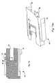
- FIG. 3 ais a perspective view of an alternative embodiment of the antenna of FIG. 3 including an external matching arm;
- FIG. 3 bis a perspective view of an alternative embodiment of the antenna of FIG. 3 a;
- FIG. 3 cis a top view of an alternative embodiment of the antenna element of FIG. 1 a;
- FIG. 3 dis a top view of an alternative embodiment of the antenna element of FIG. 3 c;
- FIG. 3 eis a top view of an alternative embodiment of the antenna element of FIG. 3 c;
- FIG. 3 fis a top view of an alternative embodiment of the antenna element of FIG. 3 c;
- FIG. 4is a top view of an antenna having multiple antenna elements according to the present invention.
- FIG. 5is a top view of an alternative embodiment of the antenna of FIG. 4 with a modified feeding structure
- FIG. 6is a top view of an alternative embodiment of the antenna of FIG. 5;
- FIG. 7is a top view of an alternative embodiment of the antenna of FIG. 5;
- FIG. 8is a top view of an alternative embodiment of the antenna of FIG. 7;
- FIG. 9is a top view of an alternative embodiment of the antenna of FIG. 7;
- FIG. 10is a top view of an alternative embodiment of the antenna of FIG. 5;
- FIG. 11 ais a top view of an alternative embodiment of an antenna according to the present invention including matching elements and filters;
- FIG. 11 bis a perspective view of the antenna of FIG. 25 .
- FIG. 12is a top view of an alternative embodiment of the antenna of FIG. 4;
- FIG. 13 ais a top view of an alternative embodiment of the antenna of FIG. 12 with a modified feeding structure
- FIG. 13 bis a graphical representation of the frequencies produced by the antenna of FIG. 13 a;
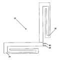
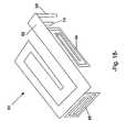
- FIG. 14is a perspective view of an alternative embodiment of an antenna according to the present invention.
- FIG. 15is a side view of the antenna of FIG. 14;
- FIG. 16is a perspective view of an alternative embodiment of an antenna according to the present invention.
- FIG. 17is a perspective view of an alternative embodiment of the antenna of FIG. 16 including an additional antenna element
- FIG. 18is a perspective view of an alternative embodiment of the antenna of FIG. 17;
- FIG. 19is a perspective view of an alternative embodiment of the antenna of FIG. 18 including an additional antenna element;
- FIG. 20is a top view of an alternative embodiment of the antenna of FIG. 5 including an additional antenna element
- FIG. 21is a top view of an alternative embodiment of the antenna of FIG. 20 with modified feeding structure
- FIG. 22is a top view of an alternative embodiment of the antenna of FIG. 20 with additional antenna elements;
- FIG. 23is a top view of an alternative embodiment of the antenna of FIG. 12 with additional antenna elements;
- FIG. 24is a top view of an alternative embodiment of the antenna of FIG. 23 with antenna elements of varying size.
- an antenna element which can be used according to the present inventionis generally designed by reference numeral 10 in FIG. 1 a .
- the antenna element 10comprises three antenna arms 12 , 14 , and 16 .
- the antenna element 10is fed through the feeding structure comprising feed line 18 and ground line 20 .
- the antenna arms 12 , 14 , and 16are configured to produce circulating current flows which cause the antenna element 10 to radiate at a low frequency (f 1 ) and a high frequency (f 2 ).
- Arms 12 and 14form a large u-shaped antenna element which is fed by feed line 18 .
- This structureproduces a current flow indicated by line 22 causing the antenna element 10 to radiate at low frequency (f 1 ).
- Arms 14 and 16form a small u-shaped antenna element which is fed through electromagnetic coupling with arm 12 , which is represented by dashed line 24 .
- This small structureproduces a current flow which causes the antenna element 10 to radiate at high frequency (f 2 ).
- This antenna element designcreates inductive and capacitive elements which create the antenna frequency bands.
- arms 12 and 16form a first capacitive part of antenna 10 and arms 14 and 16 form a second capacitive part.
- Corresponding inductive parts of the antenna 10are created between the arms 12 , 14 and 16 and a ground plate (not shown except in FIG. 15 ).
- FIGS. 2 a , 2 b and 2 cillustrate various ways to modify the inductance of antenna element 10 .
- FIG. 2 ashows adding an inductive bridge 26 between arms 12 and 16 .
- the inductive bridge 26can be used to widen the tow frequency band (f 1 ) of antenna element 10 .
- the inductive bridge 26can also be used to widen the high frequency band (f 2 ) of antenna element 10 by adjusting its placement and width.
- the effect the inductive bridge 26 has on antenna performancecan be controlled to suit many different antenna applications.
- some of the factors which determine the effect the inductive bridge 26 has on antenna 10are the width of element 12 , the width of the inductive bridge 26 , the position of the inductive bridge 26 along the length of element 12 , and the width of the gap between elements 12 and 16 .
- FIG. 2 cshows adding an inductive bridge 30 between arms 14 and 16 .
- This inductive bridge 30can be used to widen the high frequency band (f 2 ) of antenna element 10 .
- inductive bridge 30can be used to widen the low frequency band (f 1 ) of antenna element 10 by adjusting its placement and width.
- FIG. 2 dshow adding multiple inductive bridges 31 between arms 12 and 16 .
- the additional inductive bridges 31can be used to further widen the low (or high) frequency band of antenna element 10 .
- the embodiment shown in FIG. 2 dcan be configured to produce an expanded low frequency band (f 1 ) like the one shown in FIG. 2 e.
- FIG. 2 bshows inserting slots 28 into arm 12 . Slots 28 allow the length of element 12 to be shortened without effecting antenna performance.
- FIG. 2 cshows placing an inductive bridge 30 between arms 14 and 16 to widen the bandwidth at the high frequency (f 2 ), similar to the way inductive bridge 26 operates.
- f 2the high frequency
- FIGS. 2 f - 2 gshow an alternative feeding structure arrangement in which the feed line 18 cut away from arm 12 .
- the feed line 18formed from a piece of arm 12 which is cut away and folded down.
- the ground line 20is attached to the end of arm 12 .
- a matching element 21can be added to the antenna element 10 enabling additional control over the antenna element environment through frequency matching.
- Matching element 21capacitively couples with arm 12 of the antenna element 10 .
- matching element 21is connected to arm 12 .
- matching element 21is connected to feed line 18 . Whether the matching element 21 is attached to arm 12 of feed line 18 can be dictated by size considerations of the antenna application.
- the matching element 21can be configured to widen the frequency bands produced by antenna element 10 . Some of the factors which dictate the effect the matching element 21 has on the antenna element 10 include the length of the matching element 21 and the gap between matching element 21 and the antenna element arm 12 .
- the longer the length of the matching element 21the more it affects the low frequency (f 1 ) component. Conversely, the shorter the length the more it affects the high frequency (f 2 ) component.
- the gapgenerally the smaller the gap between the matching element 21 and arm 12 , the more the high frequency (f 2 ) component is affected and the larger the gap, the more the low frequency (f 1 ) component is affected.
- FIGS. 3 c - 3 fshow alternative embodiments of matching element 21 .
- FIG. 3 cshows matching element 21 extending vertically downward from the outside edge of arm 12 .
- FIG. 3 dshows matching element 21 attached to the outside edge of arm 12 and extending perpendicular under arm 12 to under arm 16 where it extends parallel under arm 16 .
- FIG. 3 eshows matching element 21 attached to the outside edge of arm 12 and extending perpendicular under arm 12 to under arm 14 where it extends parallel under arm 14 .
- FIG. 3 fshows matching element 21 attached to the outside edge of arm 12 and extending under arm 12 at one diagonal to under arm 16 where it extends at another diagonal to under arm 14 .
- the antenna 32 shown in FIG. 4comprises two antenna elements 34 and 36 fed through a signal feeding structure using feed line 38 and ground line 40 .
- antenna elements 34 and 36are arranged perpendicular to each other and are connected at their open ends. Both feed line 38 and ground line 40 are attached to element 34 but are configured to power both element 34 and element 36 . This 90 degree arrangement between elements 34 and 36 minimizes coupling between the elements and thus maximizes the bandwidth of antenna 32 .
- antenna elements 34 and 36are each configured to radiate a high frequency and a low frequency, thus producing four separate frequency bands (f 1 , f 2 , f 3 , and f 4 ).
- the structure of the antenna elements 34 and 36 and their arrangement with respect to each othercan be designed such that the low frequencies (f 1 and f 3 ) of both elements are near enough on the frequency spectrum to partially combine to form a single, enlarged low frequency band.
- the antenna 32can be designed such that the high frequencies (f 2 and f 4 ) of both elements 34 and 36 are also near enough on the frequency spectrum to partially combine to form a single, enlarged high frequency band.
- antenna elements 34 and 36should be similarly sized. However, even if elements 34 and 36 are not similarly sized, they can be configured to produce overlapping frequency bands by adjusting the arm lengths and gaps between the arms. Alternatively, the antenna 32 can be configured so that the four frequency bands (f 1 , f 2 , f 3 , and f 4 ) do not overlap allowing them to be used as in a communication system with two separate transmit and receive frequencies. Conversely to the situation described about, generally elements 34 and 36 should be different sized elements in order to produce frequency bands that do not overlap. However, even if elements 34 and 36 are similarly sized, they can be designed to produce non-overlapping frequency bands such as by adjusting the arm lengths and gaps between the arms.
- FIG. 5illustrates an alternative feeding structure for the antenna of FIG. 4 .
- ground line 40is connected to element 36 while feed line 38 is connected to element 34 .
- This feeding structurecan be used to power both elements 34 and 36 .
- This and other alternative feed structure arrangementscan be made to accommodate size constraints imposed by various antenna applications.
- FIG. 6illustrates an alternative embodiment of the antenna shown in FIG. 5 .
- elements 34 and 36are arranged at an angle 42 less than 90 degrees. This allows the overall structure of the antenna 32 to be more compact allowing it to be used for applications in which space of limited.
- the elements 34 and 36are no Longer perpendicular, coupling occurs between the elements which can reduce the bandwidth of antenna 32 .
- This couplingcan be compensated for in a variety of ways such as, among other ways, adjusting the arm lengths of each element 34 , 36 and/or adjusting the gaps between the arms.
- FIGS. 7-9illustrate various embodiments in which elements 34 and 36 are arranged parallel to each other.
- feed line 38is connected to element 34 and ground line 40 is connected to element 36 , however the feed line 38 and ground line 40 could be reversed or both be attached to either element 34 or 36 .
- the coupling between the elements 34 , 36is very high since the magnetic fields created by each element are parallel to each other.
- the elements 34 and 36are connected.
- the elements 34 and 36are separated by a distance (d) which can be used to match the elements 34 and 36 return loss and efficiency.
- the coupling created between elements 34 and 36decreases as the distance (d) between the elements increases. Conversely, the coupling is increased as the distance (d) decreases.
- the return loss of the elements 34 and 36is proportional to the magnetic coupling between the elements 34 and 36 .
- a matching element 44is added between elements 34 and 36 .
- Matching element 44can be used for frequency matching for all frequency bands produced by antenna 32 .
- matching element 44can be used to increase the bandwidth of antenna 32 .
- the Length of the antenna element arms and the gaps between the armscan be adjusted to compensate for coupling and to increase the bandwidth of antenna 32 .
- FIG. 10illustrates an alternative embodiment of FIG. 5 in which the angle between elements 34 and 36 is 180 degrees.
- the feed line 38is moved to the side (rather than the end) of element 34 in order to accommodate the connection between elements 34 and 36 .
- This arrangementcan be used in antenna applications in which the a long, narrow piece of real estate is available for the antenna.
- FIGS. 11 a and billustrate one embodiment of the invention that includes various filters and matching elements to customize and optimize operation of the antenna 46 for a particular application.
- This embodimentshows various filters 48 cut into antenna element 46 . Filters of this type, which allow element 46 to produce multiple frequency bands, are described in more detail in the co-pending applications mentioned above which have been incorporated by reference.
- Antenna 46also includes a second antenna element 52 and a matching element 54 attached to the sides of antenna element 46 .
- An additional parasitic element 56can also be included inside antenna 46 . Parasitic element 56 is feed through magnetic coupling and is configured to general additional frequency bands.
- parasitic element 56can be configured to produce overlapping frequency bands which combine with the frequency bands produced by the other antenna elements 46 , 52 or can be configured to produce non-overlapping frequency bands.
- Feed line 18 and ground line 20are shown attached to element 46 .
- antenna elements 34 and 36can also be different sizes.
- the size of an antenna element 34 , 36largely dictates its resonant frequency band, i.e. the smaller the antenna element the higher the resonant frequency band.
- the embodiment of antenna 32 shown in FIG. 12is configured to produce four separate frequency bands, which could be configured as the send and receive bands for two distinct systems such as 800 MHz and 1900 MHz.
- the different sized antenna elements 34 and 36 shown in FIG. 12could be designed to produce overlapping frequency bands by adjusting various attributes of the antenna elements such as, among other things, the length of the antenna elements arms and/or the gaps between the arms.
- the feed line 38 and ground line 40are both connected to element 36 .
- each antenna element 34 and 36can be configured with its own feed line 38 and ground line 40 .
- Designing antenna 32 with separate feeding structures for element 34 and 36may be desirable in situation in which the device that incorporates antenna 32 has more than one module.
- the devicemay have separate BluetoothTM and GSM modules. In this case, it may be desirable to separate each antenna element's feeding structure to take advantage of these separate modules.
- FIG. 13 billustrates the frequencies (f 1 , f 2 , f 3 and f 4 ) which could be produced by the embodiment of antenna 32 shown in FIG. 13 a .
- antenna element 34could be configured to produce the lower frequency send and receive bands (f 1 , f 2 ), in the 800 MHz range and antenna element 36 could be configured to produce the higher frequency send and receive bands (f 3 , f 4 ) in the 1900 MHz range.
- FIGS. 14 and 15illustrate an embodiment of antenna 32 in which elements 34 and 36 are stacked in a vertical manner. Size constraints of an antenna application may require that the separate antenna elements 34 and 36 be stacked in this vertical manner. While there is come magnetic coupling between elements 34 and 36 in this arrangement, the coupling can be controlled and minimized by, among other ways, adjusting the gap between the elements 34 , 36 and their alignment with respect to each other. In this embodiment, both elements 34 and 36 have their own feed line 38 and ground line 40 . However, the antenna 32 could be designed with one feeding structure by making one of the elements 34 or 36 parasitic as described herein with respect to other embodiment of the invention. In FIG. 15, the elements 34 and 36 are shown attached to a ground plane 58 . Similar to the embodiment illustrated in FIG. 13 a , elements 34 and 36 are different sizes and thus can be configured to produce multiple frequency bands across the spectrum. It should be noted that one advantage to the various antenna arrangements discussed herein is that antenna 32 can be designed to fit within the space constraints of various applications.
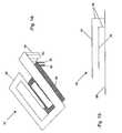
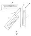
- FIG. 16illustrates still another embodiment of antenna 32 .
- antenna element 36is attached to the side of element 34 facing the same direction but at a 90 degree angle with element 34 .
- This arrangementminimizes coupling between elements 34 and 36 similar to the embodiment illustrated in FIGS. 4 and 5.
- Element 36can be attached to any arm of element 34 , facing any direction, in order to accommodate size constraints placed on the antenna 32 by particular antenna applications. Similar to the embodiment illustrated in FIG. 12, element 36 is smaller than element 34 .
- Feed line 38 and ground line 40are attached to element 34 .
- FIG. 17illustrates an alternative embodiment of the antenna of FIG. 16 .
- the antenna 60 shown in FIG. 17includes three antenna elements 62 , 64 and 66 .
- Antenna elements 64 and 66are attached to the sides of element 62 at a 90 degree angle with element 62 .
- Elements 62 , 64 and 66are all different sizes.
- each antenna element 62 , 64 , and 66can be configured to produce two frequency bands at different places on the frequency spectrum.
- the antenna 60can be configured to operate with three separate communications each at a different frequency band.
- FIG. 12-16Similar to how the antenna embodiments shown in FIGS. 12-16 can be configured to operate with two separate communication systems at different frequency bands, the antenna 60 can be configured to operate with three separate communications each at a different frequency band.
- FIG. 12-16Similar to how the antenna embodiments shown in FIGS. 12-16 can be configured to operate with two separate communication systems at different frequency bands, the antenna 60 can be configured to operate with three separate communications each at a different frequency band.
- FIG. 17shows element 66 facing in a direction opposite to elements 62 and 64 , however element 66 can be arranged in the same direction as elements 62 and 64 as shown in FIG. 18 .
- the feed line 68 and ground line 70are attached to element 62 .
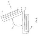
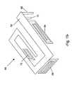
- FIG. 19illustrates an alternative embodiment of the antenna 60 shown in FIG. 18 .
- the antenna 60 shown in FIG. 19includes still another antenna element 72 attached to element 62 .
- Element 72is arranged in a semi-circular way with elements 64 and 66 in the direction of current flow in element 62 .
- element 72 , or elements 64 or 66could also be arranged in the opposite direction or any combination thereof to accommodate the size constraints placed on the antenna 60 by the particular antenna application.
- elements 62 , 64 , 66 , and 72are all different sizes and are configured to produce eight separate frequency bands in four distinct sections on the frequency spectrum (each element producing a high and low frequency in its respective section of the spectrum).
- the characteristics of the antenna elements 62 , 64 , 66 , and/or 72can be designed to allow the different-sized antenna elements to produce overlapping frequency bands.
- one of more of elements 62 , 64 , 66 , or 72could be configured to be about the same size as another element thus acting to produce frequencies bands in the same section which combine to expand to the high and low frequency bands produced by the respective elements as described above.
- the feed line 68 and ground line 70are both attached to element 62 .
- FIG. 20illustrates an alternative embodiment of the antenna shown in FIG. 5 .
- the antenna 60 shown in FIG. 20includes three antenna elements 62 , 64 , and 66 connected together. Elements 62 and 64 are arranged perpendicular to each other and element 66 is arranged between elements 62 and 64 at an angle of less than 90 degrees from element 62 . Because element 66 is not perpendicular to elements 62 and 64 , come magnetic coupling is likely to occur between elements. However, this coupling can be controlled and minimized, as described herein with respect to other embodiments of the invention, by altering various characteristics of the antenna elements or by adding matching elements.
- elements 62 , 64 , and 66are approximately the same size and thus could be configured to produce frequency bands that combine to expand the frequency bands produced by a single antenna element.
- feed Line 68is attached to element 62 and ground line 70 is attached to element 64 .
- ground line 70could be attached to element 66 . It is contemplated that other feed line/ground line arrangements are possible and within the scope of this invention.
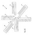
- FIG. 22illustrates an alternative embodiment of the antenna 60 shown in FIG. 21 .
- This embodiment of antenna 60includes six antenna elements 62 , 64 , 66 , 72 , 74 , and 76 attached together. While feed line 68 is shown attached to element 62 and ground Line 70 is shown attached to element 66 , the feed line 68 and ground line 70 could be attached to other elements.
- the antenna elements 62 , 64 , 66 , 72 , 74 , and 76are approximately the same size.
- the antenna elements 62 , 64 , 66 , 72 , 74 , and 76can be configured to produce frequency bands that combine to expand the overall frequency bands produced by antenna 60 .
- the elements 62 , 64 , 66 , 72 , 74 , and 76could be configured to be different sizes thus producing frequency bands in distinct sectors of the frequency spectrum as previously described for other antenna embodiment discussed herein.
- a combination of same-sized and different-sized elementscould be designed to produce expanded frequencies (caused by same-sized elements) in distinct sectors of the frequency spectrum (caused by different-sized elements). Additional elements can also be added in different planes (as previously discussed) or elements 62 , 64 , 66 , 72 , 74 , and 76 could be arranged in different planes in order to meet the space requirements of a specific application.
- FIG. 23illustrates an alternative embodiment of the antenna shown in FIG. 12 .
- the antenna 78 shown in FIG. 23includes one Large antenna element 80 and three, same-sized, smaller antenna elements 82 , 84 and 86 .
- Feed line 88 and ground line 90are attached to element 80 .
- Large element 80can be configured to produce a high and low frequency band in one sector of the frequency spectrum, while the three, same-sized, smaller antenna elements 82 , 84 , and 86 produce an expanded high and low frequency band in a higher sector of the frequency spectrum than that of the large element 80 .
- the frequency bands produced by elements 82 , 84 and 86combine to produce the expanded high and low frequency bands in the higher sector.
- FIG. 24illustrates an alternative embodiment of the antenna 78 shown in FIG. 23 .
- elements 82 , 84 , and 86are different-sized, smaller antenna elements.
- each of elements 82 , 84 and 86produce a high and low frequency band in a different sector of the frequency spectrum.
- the embodiment of the antenna 78 shown in FIG. 24can be configured to operate in four different communication systems which operate at different frequencies.
- coupling between the elements in the antennas shown in FIGS. 22-24can be controlled and/or minimized in a variety of ways and various aspects of the antenna element's design and arrangement can be altered to fit the needs of particular antenna applications.
Landscapes
- Engineering & Computer Science (AREA)
- Computer Networks & Wireless Communication (AREA)
- Variable-Direction Aerials And Aerial Arrays (AREA)
- Waveguide Aerials (AREA)
Abstract
Description
Claims (51)
Priority Applications (5)
| Application Number | Priority Date | Filing Date | Title |
|---|---|---|---|
| US10/293,465US6717551B1 (en) | 2002-11-12 | 2002-11-12 | Low-profile, multi-frequency, multi-band, magnetic dipole antenna |
| AU2003223717AAU2003223717A1 (en) | 2002-04-25 | 2003-04-25 | Low-profile, multi-frequency, multi-band, capacitively loaded magnetic dipole antenna |
| KR10-2004-7017228AKR20050007464A (en) | 2002-04-25 | 2003-04-25 | Low-profile, multi-frequency, multi-band, capacitively loaded magnetic dipole antenna |
| PCT/US2003/012725WO2003092118A1 (en) | 2002-04-25 | 2003-04-25 | Low-profile, multi-frequency, multi-band, capacitively loaded magnetic dipole antenna |
| KR1020117007589AKR101152502B1 (en) | 2002-04-25 | 2003-04-25 | Low-profile, multi-frequency, multi-band, capacitively loaded magnetic dipole antenna |
Applications Claiming Priority (1)
| Application Number | Priority Date | Filing Date | Title |
|---|---|---|---|
| US10/293,465US6717551B1 (en) | 2002-11-12 | 2002-11-12 | Low-profile, multi-frequency, multi-band, magnetic dipole antenna |
Publications (1)
| Publication Number | Publication Date |
|---|---|
| US6717551B1true US6717551B1 (en) | 2004-04-06 |
Family
ID=32030442
Family Applications (1)
| Application Number | Title | Priority Date | Filing Date |
|---|---|---|---|
| US10/293,465Expired - LifetimeUS6717551B1 (en) | 2002-04-25 | 2002-11-12 | Low-profile, multi-frequency, multi-band, magnetic dipole antenna |
Country Status (1)
| Country | Link |
|---|---|
| US (1) | US6717551B1 (en) |
Cited By (75)
| Publication number | Priority date | Publication date | Assignee | Title |
|---|---|---|---|---|
| US20040070548A1 (en)* | 2002-09-09 | 2004-04-15 | Cake Brian Victor | Physically small antenna elements and antennas based thereon |
| US20040145527A1 (en)* | 2003-01-15 | 2004-07-29 | Filtronic Lk Oy | Planar antenna structure and radio device |
| US20040252062A1 (en)* | 2003-06-13 | 2004-12-16 | Motorola, Inc. | Compact PIFA antenna for automated manufacturing |
| US20050174297A1 (en)* | 2004-02-09 | 2005-08-11 | Cake Brian V. | Compact ground-plane antenna |
| US20050270242A1 (en)* | 2004-06-02 | 2005-12-08 | Research In Motion Limited | Mobile wireless communications device comprising non-planar internal antenna without ground plane overlap |
| US20060208900A1 (en)* | 2005-01-19 | 2006-09-21 | X-Ether, Inc. | Rfid antenna |
| US20070040754A1 (en)* | 2005-08-16 | 2007-02-22 | Wistron Neweb Corp | Notebook and antenna structure thereof |
| WO2007036774A1 (en)* | 2005-09-29 | 2007-04-05 | Nokia Corporation | Dual-resonant antenna |
| US20070080885A1 (en)* | 2005-10-12 | 2007-04-12 | Mete Ozkar | Meander line capacitively-loaded magnetic dipole antenna |
| EP1819016A1 (en)* | 2006-02-10 | 2007-08-15 | Casio Hitachi Mobile Communications Co., Ltd. | Antenna apparatus |
| US20070222698A1 (en)* | 2004-09-14 | 2007-09-27 | Gregory Poilasne | Systems and methods for a capacitively-loaded loop antenna |
| US20070252770A1 (en)* | 2006-04-26 | 2007-11-01 | Fujitsu Limited | Tag-use antenna and tag using the same |
| CN100353610C (en)* | 2004-07-22 | 2007-12-05 | 上海交通大学 | Small high isolation degree plane double antenna |
| US7312762B2 (en) | 2001-10-16 | 2007-12-25 | Fractus, S.A. | Loaded antenna |
| CN100364172C (en)* | 2004-07-22 | 2008-01-23 | 上海交通大学 | Built-in mobile terminal dual antenna |
| US20080143620A1 (en)* | 2006-12-13 | 2008-06-19 | Ncr Corporation | Increasing the bandwidth of a RFID dipole tag |
| US20080231521A1 (en)* | 2004-12-30 | 2008-09-25 | Fractus, S.A. | Shaped Ground Plane For Radio Apparatus |
| US20090153430A1 (en)* | 2005-05-23 | 2009-06-18 | Chen-Ta Hung | Multi-frequency antenna suitably working in different wireless networks |
| US20090322639A1 (en)* | 2008-06-27 | 2009-12-31 | Asustek Computer Inc. | Antenna apparatus |
| CN1951133B (en)* | 2004-06-02 | 2010-05-05 | 捷讯研究有限公司 | Mobile wireless communications device comprising non-planar internal antenna and corresponding method thereof |
| US7872605B2 (en) | 2005-03-15 | 2011-01-18 | Fractus, S.A. | Slotted ground-plane used as a slot antenna or used for a PIFA antenna |
| US20110221638A1 (en)* | 2009-05-07 | 2011-09-15 | Ethertronics, Inc. | Internal lc antenna for wireless communication device |
| US20110241962A1 (en)* | 2010-03-30 | 2011-10-06 | Htc Corporation | Planar antenna and handheld device |
| US8466756B2 (en) | 2007-04-19 | 2013-06-18 | Pulse Finland Oy | Methods and apparatus for matching an antenna |
| US8473017B2 (en) | 2005-10-14 | 2013-06-25 | Pulse Finland Oy | Adjustable antenna and methods |
| US8497806B2 (en) | 2010-07-23 | 2013-07-30 | Research In Motion Limited | Mobile wireless device with multi-band loop antenna with arms defining a slotted opening and related methods |
| US8564485B2 (en) | 2005-07-25 | 2013-10-22 | Pulse Finland Oy | Adjustable multiband antenna and methods |
| US8618990B2 (en) | 2011-04-13 | 2013-12-31 | Pulse Finland Oy | Wideband antenna and methods |
| US8629813B2 (en) | 2007-08-30 | 2014-01-14 | Pusle Finland Oy | Adjustable multi-band antenna and methods |
| US8648752B2 (en) | 2011-02-11 | 2014-02-11 | Pulse Finland Oy | Chassis-excited antenna apparatus and methods |
| US8723733B2 (en) | 2010-09-29 | 2014-05-13 | Qualcomm Incorporated | Multiband antenna for a mobile device |
| US8749438B2 (en) | 2010-09-29 | 2014-06-10 | Qualcomm Incorporated | Multiband antenna for a mobile device |
| US8786499B2 (en) | 2005-10-03 | 2014-07-22 | Pulse Finland Oy | Multiband antenna system and methods |
| US8830135B2 (en) | 2012-02-16 | 2014-09-09 | Ultra Electronics Tcs Inc. | Dipole antenna element with independently tunable sleeve |
| US8847833B2 (en) | 2009-12-29 | 2014-09-30 | Pulse Finland Oy | Loop resonator apparatus and methods for enhanced field control |
| US8866689B2 (en) | 2011-07-07 | 2014-10-21 | Pulse Finland Oy | Multi-band antenna and methods for long term evolution wireless system |
| US8988296B2 (en) | 2012-04-04 | 2015-03-24 | Pulse Finland Oy | Compact polarized antenna and methods |
| US9123990B2 (en) | 2011-10-07 | 2015-09-01 | Pulse Finland Oy | Multi-feed antenna apparatus and methods |
| TWI502815B (en)* | 2012-08-20 | 2015-10-01 | Hon Hai Prec Ind Co Ltd | Dual frequency antenna |
| US9203154B2 (en) | 2011-01-25 | 2015-12-01 | Pulse Finland Oy | Multi-resonance antenna, antenna module, radio device and methods |
| US9246210B2 (en) | 2010-02-18 | 2016-01-26 | Pulse Finland Oy | Antenna with cover radiator and methods |
| US9350081B2 (en) | 2014-01-14 | 2016-05-24 | Pulse Finland Oy | Switchable multi-radiator high band antenna apparatus |
| US9406998B2 (en) | 2010-04-21 | 2016-08-02 | Pulse Finland Oy | Distributed multiband antenna and methods |
| US9450291B2 (en) | 2011-07-25 | 2016-09-20 | Pulse Finland Oy | Multiband slot loop antenna apparatus and methods |
| US9461371B2 (en) | 2009-11-27 | 2016-10-04 | Pulse Finland Oy | MIMO antenna and methods |
| US9484619B2 (en) | 2011-12-21 | 2016-11-01 | Pulse Finland Oy | Switchable diversity antenna apparatus and methods |
| US9531058B2 (en) | 2011-12-20 | 2016-12-27 | Pulse Finland Oy | Loosely-coupled radio antenna apparatus and methods |
| US9590308B2 (en) | 2013-12-03 | 2017-03-07 | Pulse Electronics, Inc. | Reduced surface area antenna apparatus and mobile communications devices incorporating the same |
| US9634383B2 (en) | 2013-06-26 | 2017-04-25 | Pulse Finland Oy | Galvanically separated non-interacting antenna sector apparatus and methods |
| US9647338B2 (en) | 2013-03-11 | 2017-05-09 | Pulse Finland Oy | Coupled antenna structure and methods |
| US9673507B2 (en) | 2011-02-11 | 2017-06-06 | Pulse Finland Oy | Chassis-excited antenna apparatus and methods |
| US9680212B2 (en) | 2013-11-20 | 2017-06-13 | Pulse Finland Oy | Capacitive grounding methods and apparatus for mobile devices |
| US9722308B2 (en) | 2014-08-28 | 2017-08-01 | Pulse Finland Oy | Low passive intermodulation distributed antenna system for multiple-input multiple-output systems and methods of use |
| US9755314B2 (en) | 2001-10-16 | 2017-09-05 | Fractus S.A. | Loaded antenna |
| US9761951B2 (en) | 2009-11-03 | 2017-09-12 | Pulse Finland Oy | Adjustable antenna apparatus and methods |
| US9906260B2 (en) | 2015-07-30 | 2018-02-27 | Pulse Finland Oy | Sensor-based closed loop antenna swapping apparatus and methods |
| US9948002B2 (en) | 2014-08-26 | 2018-04-17 | Pulse Finland Oy | Antenna apparatus with an integrated proximity sensor and methods |
| US9973228B2 (en) | 2014-08-26 | 2018-05-15 | Pulse Finland Oy | Antenna apparatus with an integrated proximity sensor and methods |
| US9979078B2 (en) | 2012-10-25 | 2018-05-22 | Pulse Finland Oy | Modular cell antenna apparatus and methods |
| US10069209B2 (en) | 2012-11-06 | 2018-09-04 | Pulse Finland Oy | Capacitively coupled antenna apparatus and methods |
| US10074888B2 (en) | 2015-04-03 | 2018-09-11 | NXT-ID, Inc. | Accordion antenna structure |
| US10079428B2 (en) | 2013-03-11 | 2018-09-18 | Pulse Finland Oy | Coupled antenna structure and methods |
| US10109918B2 (en) | 2016-01-22 | 2018-10-23 | Airgain Incorporated | Multi-element antenna for multiple bands of operation and method therefor |
| US10120065B2 (en)* | 2015-07-17 | 2018-11-06 | Wistron Corp. | Antenna array |
| US10263341B2 (en) | 2016-04-19 | 2019-04-16 | Ethertronics, Inc. | Low profile antenna system |
| US10530039B1 (en)* | 2019-05-06 | 2020-01-07 | Climax Technology Co., Ltd. | Antenna extension device |
| WO2020106596A1 (en)* | 2018-11-20 | 2020-05-28 | Corning Optical Communications Rf Llc | Monolithic antenna integrated radio frequency connector |
| US10756435B2 (en) | 2016-04-18 | 2020-08-25 | Ethertronics, Inc. | Low profile antenna module |
| US11018426B2 (en)* | 2019-02-13 | 2021-05-25 | Wistron Corp. | Antenna structure |
| US20210376478A1 (en)* | 2020-05-28 | 2021-12-02 | Avx Antenna, Inc. D/B/A Ethertronics, Inc. | Modal Antenna System Including Closed-Loop Parasitic Element |
| US11742590B2 (en) | 2021-01-07 | 2023-08-29 | KYOCERA AVX Components (San Diego), Inc. | Circularly polarized array antenna for millimeter wave communications |
| US11742580B2 (en) | 2020-07-28 | 2023-08-29 | KYOCERA AVX Components (San Diego), Inc. | Multifeed antenna system with capacitively coupled feed elements |
| US11881618B2 (en) | 2020-07-10 | 2024-01-23 | KYOCERA AVX Components (San Diego), Inc. | Antenna system with coupled region |
| US11936119B2 (en) | 2021-01-29 | 2024-03-19 | KYOCERA AVX Components (San Diego), Inc. | Isolated magnetic dipole antennas having angled edges for improved tuning |
| EP4380066A1 (en) | 2022-11-29 | 2024-06-05 | Thales Dis France Sas | Inductively tuned antenna structure for different wireless chips and frequencies |
Citations (23)
| Publication number | Priority date | Publication date | Assignee | Title |
|---|---|---|---|---|
| US3721990A (en) | 1971-12-27 | 1973-03-20 | Rca Corp | Physically small combined loop and dipole all channel television antenna system |
| JPS5612102A (en) | 1979-07-11 | 1981-02-06 | Nippon Telegr & Teleph Corp <Ntt> | Broad-band reversed-l-shaped antenna |
| US4684952A (en) | 1982-09-24 | 1987-08-04 | Ball Corporation | Microstrip reflectarray for satellite communication and radar cross-section enhancement or reduction |
| EP0604338A1 (en) | 1992-12-23 | 1994-06-29 | France Telecom | Space-saving broadband antenna with corresponding transceiver |
| US5450090A (en) | 1994-07-20 | 1995-09-12 | The Charles Stark Draper Laboratory, Inc. | Multilayer miniaturized microstrip antenna |
| JPH0955621A (en) | 1995-08-14 | 1997-02-25 | Toyo Commun Equip Co Ltd | Array antenna |
| US5627550A (en) | 1995-06-15 | 1997-05-06 | Nokia Mobile Phones Ltd. | Wideband double C-patch antenna including gap-coupled parasitic elements |
| US5781158A (en) | 1995-04-25 | 1998-07-14 | Young Hoek Ko | Electric/magnetic microstrip antenna |
| US5943020A (en) | 1996-03-13 | 1999-08-24 | Ascom Tech Ag | Flat three-dimensional antenna |
| EP0942488A2 (en) | 1998-02-24 | 1999-09-15 | Murata Manufacturing Co., Ltd. | Antenna device and radio device comprising the same |
| US6008762A (en) | 1997-03-31 | 1999-12-28 | Qualcomm Incorporated | Folded quarter-wave patch antenna |
| JP2000031735A (en) | 1998-03-24 | 2000-01-28 | Ddi Corp | Adaptive array antenna device |
| JP2000068736A (en) | 1998-08-21 | 2000-03-03 | Toshiba Corp | Multi-frequency antenna |
| US6114996A (en) | 1997-03-31 | 2000-09-05 | Qualcomm Incorporated | Increased bandwidth patch antenna |
| US6133880A (en) | 1997-12-11 | 2000-10-17 | Alcatel | Short-circuit microstrip antenna and device including that antenna |
| EP1067627A1 (en) | 1999-07-09 | 2001-01-10 | Robert Bosch Gmbh | Dual band radio apparatus |
| US6195051B1 (en) | 1999-04-08 | 2001-02-27 | Motorola, Inc. | Microstrip antenna and method of forming same |
| US6304222B1 (en) | 1997-12-22 | 2001-10-16 | Nortel Networks Limited | Radio communications handset antenna arrangements |
| US6323810B1 (en) | 2001-03-06 | 2001-11-27 | Ethertronics, Inc. | Multimode grounded finger patch antenna |
| US6329955B1 (en)* | 1998-10-26 | 2001-12-11 | Tdk Rf Solutions Inc. | Broadband antenna incorporating both electric and magnetic dipole radiators |
| US6348894B1 (en) | 2000-05-10 | 2002-02-19 | Nokia Mobile Phones Ltd. | Radio frequency antenna |
| US6456243B1 (en)* | 2001-06-26 | 2002-09-24 | Ethertronics, Inc. | Multi frequency magnetic dipole antenna structures and methods of reusing the volume of an antenna |
| US6486848B1 (en)* | 2001-08-24 | 2002-11-26 | Gregory Poilasne | Circular polarization antennas and methods |
- 2002
- 2002-11-12USUS10/293,465patent/US6717551B1/ennot_activeExpired - Lifetime
Patent Citations (23)
| Publication number | Priority date | Publication date | Assignee | Title |
|---|---|---|---|---|
| US3721990A (en) | 1971-12-27 | 1973-03-20 | Rca Corp | Physically small combined loop and dipole all channel television antenna system |
| JPS5612102A (en) | 1979-07-11 | 1981-02-06 | Nippon Telegr & Teleph Corp <Ntt> | Broad-band reversed-l-shaped antenna |
| US4684952A (en) | 1982-09-24 | 1987-08-04 | Ball Corporation | Microstrip reflectarray for satellite communication and radar cross-section enhancement or reduction |
| EP0604338A1 (en) | 1992-12-23 | 1994-06-29 | France Telecom | Space-saving broadband antenna with corresponding transceiver |
| US5450090A (en) | 1994-07-20 | 1995-09-12 | The Charles Stark Draper Laboratory, Inc. | Multilayer miniaturized microstrip antenna |
| US5781158A (en) | 1995-04-25 | 1998-07-14 | Young Hoek Ko | Electric/magnetic microstrip antenna |
| US5627550A (en) | 1995-06-15 | 1997-05-06 | Nokia Mobile Phones Ltd. | Wideband double C-patch antenna including gap-coupled parasitic elements |
| JPH0955621A (en) | 1995-08-14 | 1997-02-25 | Toyo Commun Equip Co Ltd | Array antenna |
| US5943020A (en) | 1996-03-13 | 1999-08-24 | Ascom Tech Ag | Flat three-dimensional antenna |
| US6008762A (en) | 1997-03-31 | 1999-12-28 | Qualcomm Incorporated | Folded quarter-wave patch antenna |
| US6114996A (en) | 1997-03-31 | 2000-09-05 | Qualcomm Incorporated | Increased bandwidth patch antenna |
| US6133880A (en) | 1997-12-11 | 2000-10-17 | Alcatel | Short-circuit microstrip antenna and device including that antenna |
| US6304222B1 (en) | 1997-12-22 | 2001-10-16 | Nortel Networks Limited | Radio communications handset antenna arrangements |
| EP0942488A2 (en) | 1998-02-24 | 1999-09-15 | Murata Manufacturing Co., Ltd. | Antenna device and radio device comprising the same |
| JP2000031735A (en) | 1998-03-24 | 2000-01-28 | Ddi Corp | Adaptive array antenna device |
| JP2000068736A (en) | 1998-08-21 | 2000-03-03 | Toshiba Corp | Multi-frequency antenna |
| US6329955B1 (en)* | 1998-10-26 | 2001-12-11 | Tdk Rf Solutions Inc. | Broadband antenna incorporating both electric and magnetic dipole radiators |
| US6195051B1 (en) | 1999-04-08 | 2001-02-27 | Motorola, Inc. | Microstrip antenna and method of forming same |
| EP1067627A1 (en) | 1999-07-09 | 2001-01-10 | Robert Bosch Gmbh | Dual band radio apparatus |
| US6348894B1 (en) | 2000-05-10 | 2002-02-19 | Nokia Mobile Phones Ltd. | Radio frequency antenna |
| US6323810B1 (en) | 2001-03-06 | 2001-11-27 | Ethertronics, Inc. | Multimode grounded finger patch antenna |
| US6456243B1 (en)* | 2001-06-26 | 2002-09-24 | Ethertronics, Inc. | Multi frequency magnetic dipole antenna structures and methods of reusing the volume of an antenna |
| US6486848B1 (en)* | 2001-08-24 | 2002-11-26 | Gregory Poilasne | Circular polarization antennas and methods |
Non-Patent Citations (1)
| Title |
|---|
| International Search Report from PCT Application No. PCT/US 02/20242. |
Cited By (137)
| Publication number | Priority date | Publication date | Assignee | Title |
|---|---|---|---|---|
| US20090237316A1 (en)* | 2001-10-16 | 2009-09-24 | Carles Puente Baliarda | Loaded antenna |
| US7541997B2 (en) | 2001-10-16 | 2009-06-02 | Fractus, S.A. | Loaded antenna |
| US7312762B2 (en) | 2001-10-16 | 2007-12-25 | Fractus, S.A. | Loaded antenna |
| US9755314B2 (en) | 2001-10-16 | 2017-09-05 | Fractus S.A. | Loaded antenna |
| US20040070548A1 (en)* | 2002-09-09 | 2004-04-15 | Cake Brian Victor | Physically small antenna elements and antennas based thereon |
| US6888511B2 (en)* | 2002-09-09 | 2005-05-03 | Brian Victor Cake | Physically small antenna elements and antennas based thereon |
| US20040145527A1 (en)* | 2003-01-15 | 2004-07-29 | Filtronic Lk Oy | Planar antenna structure and radio device |
| US7501983B2 (en)* | 2003-01-15 | 2009-03-10 | Lk Products Oy | Planar antenna structure and radio device |
| KR100834838B1 (en)* | 2003-06-13 | 2008-06-03 | 모토로라 인코포레이티드 | Compact PIFA antenna for automated manufacturing |
| US6850200B2 (en)* | 2003-06-13 | 2005-02-01 | Motorola, Inc. | Compact PIFA antenna for automated manufacturing |
| WO2005001990A1 (en)* | 2003-06-13 | 2005-01-06 | Motorola, Inc. | Compact pifa antenna for automated manufacturing |
| US20040252062A1 (en)* | 2003-06-13 | 2004-12-16 | Motorola, Inc. | Compact PIFA antenna for automated manufacturing |
| US20050174297A1 (en)* | 2004-02-09 | 2005-08-11 | Cake Brian V. | Compact ground-plane antenna |
| US7068230B2 (en) | 2004-06-02 | 2006-06-27 | Research In Motion Limited | Mobile wireless communications device comprising multi-frequency band antenna and related methods |
| AU2005251259B2 (en)* | 2004-06-02 | 2007-12-13 | Google Technology Holdings LLC | Mobile wireless communications device comprising multi-frequency band antenna and related methods |
| US20060208952A1 (en)* | 2004-06-02 | 2006-09-21 | Research In Motion Limited | Mobile wireless communications device comprising non-planar internal antenna without ground plane overlap |
| US20060214858A1 (en)* | 2004-06-02 | 2006-09-28 | Research In Motion Limited | Mobile wireless communications device comprising multi-frequency band antenna and related methods |
| US8018385B2 (en) | 2004-06-02 | 2011-09-13 | Motorola Mobility, Inc. | Mobile wireless communications device comprising non-planar internal antenna without ground plane overlap |
| US8004469B2 (en) | 2004-06-02 | 2011-08-23 | Motorola Mobility, Inc. | Mobile wireless communications device comprising multi-frequency band antenna and related methods |
| US7088294B2 (en) | 2004-06-02 | 2006-08-08 | Research In Motion Limited | Mobile wireless communications device comprising a top-mounted auxiliary input/output device and a bottom-mounted antenna |
| US7839343B2 (en) | 2004-06-02 | 2010-11-23 | Motorola, Inc. | Mobile wireless communications device comprising a top-mounted auxiliary input/output device and a bottom-mounted antenna |
| US7256744B2 (en) | 2004-06-02 | 2007-08-14 | Research In Motion Limited | Mobile wireless communications device comprising non-planar internal antenna without ground plane overlap |
| US20100182208A1 (en)* | 2004-06-02 | 2010-07-22 | Research In Motion Limited | Mobile wireless communications device comprising non-planar internal antenna without ground plane overlap |
| US7271772B2 (en) | 2004-06-02 | 2007-09-18 | Research In Motion Limited | Mobile wireless communications device comprising multi-frequency band antenna and related methods |
| US20050270242A1 (en)* | 2004-06-02 | 2005-12-08 | Research In Motion Limited | Mobile wireless communications device comprising non-planar internal antenna without ground plane overlap |
| US20050270241A1 (en)* | 2004-06-02 | 2005-12-08 | Research In Motion Limited | Mobile wireless communications device comprising multi-frequency band antenna and related methods |
| US20070247389A1 (en)* | 2004-06-02 | 2007-10-25 | Research In Motion Limited | Mobile wireless communications device comprising non-planar internal antenna without ground plane overlap |
| US20070252774A1 (en)* | 2004-06-02 | 2007-11-01 | Research In Motion Limited | Mobile wireless communications device comprising multi-frequency band antenna and related methods |
| CN1951133B (en)* | 2004-06-02 | 2010-05-05 | 捷讯研究有限公司 | Mobile wireless communications device comprising non-planar internal antenna and corresponding method thereof |
| US7482985B2 (en) | 2004-06-02 | 2009-01-27 | Research In Motion Limited | Mobile wireless communications device comprising multi-frequency band antenna and related methods |
| US7091911B2 (en) | 2004-06-02 | 2006-08-15 | Research In Motion Limited | Mobile wireless communications device comprising non-planar internal antenna without ground plane overlap |
| WO2005120105A1 (en)* | 2004-06-02 | 2005-12-15 | Research In Motion Limited | Mobile wireless communications device comprising multi-frequency band antenna and related methods |
| US20080291099A1 (en)* | 2004-06-02 | 2008-11-27 | Research In Motion Limited | Mobile Wireless Communications Device Comprising Non-Planar Internal Antenna Without Ground Plane Overlap |
| US20050270240A1 (en)* | 2004-06-02 | 2005-12-08 | Research In Motion Limited | Mobile wireless communications device comprising a top-mounted auxiliary input/output device and a bottom-mounted antenna |
| US7705792B2 (en) | 2004-06-02 | 2010-04-27 | Research In Motion Limited | Mobile wireless communications device comprising non-planar internal antenna without ground plane overlap |
| US7403165B2 (en) | 2004-06-02 | 2008-07-22 | Research In Motion Limited | Mobile wireless communications device comprising non-planar internal antenna without ground plane overlap |
| US7405703B2 (en) | 2004-06-02 | 2008-07-29 | Research In Motion Limited | Mobile wireless communications device comprising a top-mounted auxiliary input/output device and a bottom-mounted antenna |
| US7696935B2 (en) | 2004-06-02 | 2010-04-13 | Research In Motion Limited | Mobile wireless communications device comprising multi-frequency band antenna and related methods |
| US20100022268A1 (en)* | 2004-06-02 | 2010-01-28 | Research In Motion Limited | Mobile wireless communications device comprising a top-mounted auxiliary input/output device and a bottom-mounted antenna |
| US20080272966A1 (en)* | 2004-06-02 | 2008-11-06 | Research In Motion Limited | Mobile wireless communications device comprising multi-frequency band antenna and related methods |
| US7612726B2 (en) | 2004-06-02 | 2009-11-03 | Research In Motion Limited | Mobile wireless communications device comprising a top-mounted auxiliary input/output device and a bottom-mounted antenna |
| US20080287171A1 (en)* | 2004-06-02 | 2008-11-20 | Research In Motion Limited | Mobile wireless communications device comprising a top-mounted auxiliary input/output device and a bottom-mounted antenna |
| CN100364172C (en)* | 2004-07-22 | 2008-01-23 | 上海交通大学 | Built-in mobile terminal dual antenna |
| CN100353610C (en)* | 2004-07-22 | 2007-12-05 | 上海交通大学 | Small high isolation degree plane double antenna |
| US20070222698A1 (en)* | 2004-09-14 | 2007-09-27 | Gregory Poilasne | Systems and methods for a capacitively-loaded loop antenna |
| US7760151B2 (en) | 2004-09-14 | 2010-07-20 | Kyocera Corporation | Systems and methods for a capacitively-loaded loop antenna |
| US7932863B2 (en) | 2004-12-30 | 2011-04-26 | Fractus, S.A. | Shaped ground plane for radio apparatus |
| US20080231521A1 (en)* | 2004-12-30 | 2008-09-25 | Fractus, S.A. | Shaped Ground Plane For Radio Apparatus |
| US20110156975A1 (en)* | 2004-12-30 | 2011-06-30 | Jaume Anguera Pros | Shaped ground plane for radio apparatus |
| US20060208900A1 (en)* | 2005-01-19 | 2006-09-21 | X-Ether, Inc. | Rfid antenna |
| US7714794B2 (en)* | 2005-01-19 | 2010-05-11 | Behzad Tavassoli Hozouri | RFID antenna |
| US8593360B2 (en) | 2005-03-15 | 2013-11-26 | Fractus, S.A. | Slotted ground-plane used as a slot antenna or used for a PIFA antenna |
| US8111199B2 (en) | 2005-03-15 | 2012-02-07 | Fractus, S.A. | Slotted ground-plane used as a slot antenna or used for a PIFA antenna |
| US20110068995A1 (en)* | 2005-03-15 | 2011-03-24 | Carles Puente Baliarda | Slotted ground-plane used as a slot antenna or used for a pifa antenna |
| US7872605B2 (en) | 2005-03-15 | 2011-01-18 | Fractus, S.A. | Slotted ground-plane used as a slot antenna or used for a PIFA antenna |
| US20090153430A1 (en)* | 2005-05-23 | 2009-06-18 | Chen-Ta Hung | Multi-frequency antenna suitably working in different wireless networks |
| US7924230B2 (en) | 2005-05-23 | 2011-04-12 | Hon Hai Precision Ind. Co., Ltd. | Multi-frequency antenna suitably working in different wireless networks |
| US8564485B2 (en) | 2005-07-25 | 2013-10-22 | Pulse Finland Oy | Adjustable multiband antenna and methods |
| US7535422B2 (en)* | 2005-08-16 | 2009-05-19 | Wistron Neweb Corp. | Notebook and antenna structure thereof |
| US20070040754A1 (en)* | 2005-08-16 | 2007-02-22 | Wistron Neweb Corp | Notebook and antenna structure thereof |
| WO2007036774A1 (en)* | 2005-09-29 | 2007-04-05 | Nokia Corporation | Dual-resonant antenna |
| US7242364B2 (en) | 2005-09-29 | 2007-07-10 | Nokia Corporation | Dual-resonant antenna |
| US8786499B2 (en) | 2005-10-03 | 2014-07-22 | Pulse Finland Oy | Multiband antenna system and methods |
| US7274338B2 (en)* | 2005-10-12 | 2007-09-25 | Kyocera Corporation | Meander line capacitively-loaded magnetic dipole antenna |
| US20070080885A1 (en)* | 2005-10-12 | 2007-04-12 | Mete Ozkar | Meander line capacitively-loaded magnetic dipole antenna |
| US8473017B2 (en) | 2005-10-14 | 2013-06-25 | Pulse Finland Oy | Adjustable antenna and methods |
| WO2007084989A3 (en)* | 2006-01-19 | 2008-11-20 | Transpacific Technologies Llc | Rfid antenna |
| US20090033580A1 (en)* | 2006-01-19 | 2009-02-05 | Transpacific Technologies, Llc | RFID Antenna |
| KR100849810B1 (en) | 2006-02-10 | 2008-07-31 | 가시오 히타치 모바일 커뮤니케이션즈 컴퍼니 리미티드 | Antenna device |
| EP1819016A1 (en)* | 2006-02-10 | 2007-08-15 | Casio Hitachi Mobile Communications Co., Ltd. | Antenna apparatus |
| US7554495B2 (en) | 2006-02-10 | 2009-06-30 | Casio Hitachi Mobile Communications Co., Ltd. | Antenna apparatus |
| US7538738B2 (en)* | 2006-04-26 | 2009-05-26 | Fujitsu Limited | Tag-use antenna and tag using the same |
| US20090096701A1 (en)* | 2006-04-26 | 2009-04-16 | Manabu Kai | Tag-use antenna and tag using the same |
| US7928921B2 (en) | 2006-04-26 | 2011-04-19 | Fujitsu Limited | Tag-use antenna and tag using the same |
| US20070252770A1 (en)* | 2006-04-26 | 2007-11-01 | Fujitsu Limited | Tag-use antenna and tag using the same |
| US20080143620A1 (en)* | 2006-12-13 | 2008-06-19 | Ncr Corporation | Increasing the bandwidth of a RFID dipole tag |
| US8466756B2 (en) | 2007-04-19 | 2013-06-18 | Pulse Finland Oy | Methods and apparatus for matching an antenna |
| US8629813B2 (en) | 2007-08-30 | 2014-01-14 | Pusle Finland Oy | Adjustable multi-band antenna and methods |
| US20090322639A1 (en)* | 2008-06-27 | 2009-12-31 | Asustek Computer Inc. | Antenna apparatus |
| US20110221638A1 (en)* | 2009-05-07 | 2011-09-15 | Ethertronics, Inc. | Internal lc antenna for wireless communication device |
| US9761951B2 (en) | 2009-11-03 | 2017-09-12 | Pulse Finland Oy | Adjustable antenna apparatus and methods |
| US9461371B2 (en) | 2009-11-27 | 2016-10-04 | Pulse Finland Oy | MIMO antenna and methods |
| US8847833B2 (en) | 2009-12-29 | 2014-09-30 | Pulse Finland Oy | Loop resonator apparatus and methods for enhanced field control |
| US9246210B2 (en) | 2010-02-18 | 2016-01-26 | Pulse Finland Oy | Antenna with cover radiator and methods |
| US9142876B2 (en)* | 2010-03-30 | 2015-09-22 | Htc Corporation | Planar antenna and handheld device |
| US20110241962A1 (en)* | 2010-03-30 | 2011-10-06 | Htc Corporation | Planar antenna and handheld device |
| US9406998B2 (en) | 2010-04-21 | 2016-08-02 | Pulse Finland Oy | Distributed multiband antenna and methods |
| US8648751B2 (en) | 2010-07-23 | 2014-02-11 | Blackberry Limited | Mobile wireless device with multi-band loop antenna with arms defining a slotted opening and related methods |
| US8497806B2 (en) | 2010-07-23 | 2013-07-30 | Research In Motion Limited | Mobile wireless device with multi-band loop antenna with arms defining a slotted opening and related methods |
| US8749438B2 (en) | 2010-09-29 | 2014-06-10 | Qualcomm Incorporated | Multiband antenna for a mobile device |
| US8723733B2 (en) | 2010-09-29 | 2014-05-13 | Qualcomm Incorporated | Multiband antenna for a mobile device |
| US9203154B2 (en) | 2011-01-25 | 2015-12-01 | Pulse Finland Oy | Multi-resonance antenna, antenna module, radio device and methods |
| US9917346B2 (en) | 2011-02-11 | 2018-03-13 | Pulse Finland Oy | Chassis-excited antenna apparatus and methods |
| US9673507B2 (en) | 2011-02-11 | 2017-06-06 | Pulse Finland Oy | Chassis-excited antenna apparatus and methods |
| US8648752B2 (en) | 2011-02-11 | 2014-02-11 | Pulse Finland Oy | Chassis-excited antenna apparatus and methods |
| US8618990B2 (en) | 2011-04-13 | 2013-12-31 | Pulse Finland Oy | Wideband antenna and methods |
| US8866689B2 (en) | 2011-07-07 | 2014-10-21 | Pulse Finland Oy | Multi-band antenna and methods for long term evolution wireless system |
| US9450291B2 (en) | 2011-07-25 | 2016-09-20 | Pulse Finland Oy | Multiband slot loop antenna apparatus and methods |
| US9123990B2 (en) | 2011-10-07 | 2015-09-01 | Pulse Finland Oy | Multi-feed antenna apparatus and methods |
| US9531058B2 (en) | 2011-12-20 | 2016-12-27 | Pulse Finland Oy | Loosely-coupled radio antenna apparatus and methods |
| US9484619B2 (en) | 2011-12-21 | 2016-11-01 | Pulse Finland Oy | Switchable diversity antenna apparatus and methods |
| US8830135B2 (en) | 2012-02-16 | 2014-09-09 | Ultra Electronics Tcs Inc. | Dipole antenna element with independently tunable sleeve |
| US9509054B2 (en) | 2012-04-04 | 2016-11-29 | Pulse Finland Oy | Compact polarized antenna and methods |
| US8988296B2 (en) | 2012-04-04 | 2015-03-24 | Pulse Finland Oy | Compact polarized antenna and methods |
| TWI502815B (en)* | 2012-08-20 | 2015-10-01 | Hon Hai Prec Ind Co Ltd | Dual frequency antenna |
| US9979078B2 (en) | 2012-10-25 | 2018-05-22 | Pulse Finland Oy | Modular cell antenna apparatus and methods |
| US10069209B2 (en) | 2012-11-06 | 2018-09-04 | Pulse Finland Oy | Capacitively coupled antenna apparatus and methods |
| US10079428B2 (en) | 2013-03-11 | 2018-09-18 | Pulse Finland Oy | Coupled antenna structure and methods |
| US9647338B2 (en) | 2013-03-11 | 2017-05-09 | Pulse Finland Oy | Coupled antenna structure and methods |
| US9634383B2 (en) | 2013-06-26 | 2017-04-25 | Pulse Finland Oy | Galvanically separated non-interacting antenna sector apparatus and methods |
| US9680212B2 (en) | 2013-11-20 | 2017-06-13 | Pulse Finland Oy | Capacitive grounding methods and apparatus for mobile devices |
| US9590308B2 (en) | 2013-12-03 | 2017-03-07 | Pulse Electronics, Inc. | Reduced surface area antenna apparatus and mobile communications devices incorporating the same |
| US9350081B2 (en) | 2014-01-14 | 2016-05-24 | Pulse Finland Oy | Switchable multi-radiator high band antenna apparatus |
| US9948002B2 (en) | 2014-08-26 | 2018-04-17 | Pulse Finland Oy | Antenna apparatus with an integrated proximity sensor and methods |
| US9973228B2 (en) | 2014-08-26 | 2018-05-15 | Pulse Finland Oy | Antenna apparatus with an integrated proximity sensor and methods |
| US9722308B2 (en) | 2014-08-28 | 2017-08-01 | Pulse Finland Oy | Low passive intermodulation distributed antenna system for multiple-input multiple-output systems and methods of use |
| US10461396B2 (en) | 2015-04-03 | 2019-10-29 | Fit Pay, Inc. | System and method for low-power close-proximity communications and energy transfer using a miniature multi-purpose antenna |
| US10074888B2 (en) | 2015-04-03 | 2018-09-11 | NXT-ID, Inc. | Accordion antenna structure |
| US10120065B2 (en)* | 2015-07-17 | 2018-11-06 | Wistron Corp. | Antenna array |
| US9906260B2 (en) | 2015-07-30 | 2018-02-27 | Pulse Finland Oy | Sensor-based closed loop antenna swapping apparatus and methods |
| US10109918B2 (en) | 2016-01-22 | 2018-10-23 | Airgain Incorporated | Multi-element antenna for multiple bands of operation and method therefor |
| US11251529B2 (en) | 2016-04-18 | 2022-02-15 | Avx Antenna, Inc. | Low profile antenna module |
| US10756435B2 (en) | 2016-04-18 | 2020-08-25 | Ethertronics, Inc. | Low profile antenna module |
| US10263341B2 (en) | 2016-04-19 | 2019-04-16 | Ethertronics, Inc. | Low profile antenna system |
| US10693234B2 (en) | 2016-04-19 | 2020-06-23 | Ethertronics, Inc. | Low profile antenna system |
| WO2020106596A1 (en)* | 2018-11-20 | 2020-05-28 | Corning Optical Communications Rf Llc | Monolithic antenna integrated radio frequency connector |
| US11909097B2 (en) | 2018-11-20 | 2024-02-20 | Corning Optical Communications Rf Llc | Monolithic antenna integrated radio frequency connector |
| US11018426B2 (en)* | 2019-02-13 | 2021-05-25 | Wistron Corp. | Antenna structure |
| US10530039B1 (en)* | 2019-05-06 | 2020-01-07 | Climax Technology Co., Ltd. | Antenna extension device |
| US11735826B2 (en)* | 2020-05-28 | 2023-08-22 | KYOCERA AVX Components (San Diego), Inc. | Modal antenna system including closed-loop parasitic element |
| US20210376478A1 (en)* | 2020-05-28 | 2021-12-02 | Avx Antenna, Inc. D/B/A Ethertronics, Inc. | Modal Antenna System Including Closed-Loop Parasitic Element |
| US11881618B2 (en) | 2020-07-10 | 2024-01-23 | KYOCERA AVX Components (San Diego), Inc. | Antenna system with coupled region |
| US11742580B2 (en) | 2020-07-28 | 2023-08-29 | KYOCERA AVX Components (San Diego), Inc. | Multifeed antenna system with capacitively coupled feed elements |
| US11742590B2 (en) | 2021-01-07 | 2023-08-29 | KYOCERA AVX Components (San Diego), Inc. | Circularly polarized array antenna for millimeter wave communications |
| US11936119B2 (en) | 2021-01-29 | 2024-03-19 | KYOCERA AVX Components (San Diego), Inc. | Isolated magnetic dipole antennas having angled edges for improved tuning |
| EP4380066A1 (en) | 2022-11-29 | 2024-06-05 | Thales Dis France Sas | Inductively tuned antenna structure for different wireless chips and frequencies |
| WO2024115487A1 (en) | 2022-11-29 | 2024-06-06 | Thales Dis France Sas | Inductively tuned antenna structure for different wireless chips and frequencies |
Similar Documents
| Publication | Publication Date | Title |
|---|---|---|
| US6717551B1 (en) | Low-profile, multi-frequency, multi-band, magnetic dipole antenna | |
| US12170410B2 (en) | Antenna with multiple coupled regions | |
| US9190733B2 (en) | Antenna with multiple coupled regions | |
| US6917335B2 (en) | Antenna with shorted active and passive planar loops and method of making the same | |
| US6943730B2 (en) | Low-profile, multi-frequency, multi-band, capacitively loaded magnetic dipole antenna | |
| US6573869B2 (en) | Multiband PIFA antenna for portable devices | |
| JP5178970B2 (en) | ANTENNA DEVICE AND WIRELESS COMMUNICATION DEVICE | |
| JP3660623B2 (en) | Antenna device | |
| US9620848B2 (en) | Dual band antenna | |
| US20100295743A1 (en) | Antenna Structure With Reconfigurable Pattern And Manufacturing Method Thereof | |
| US20100182203A1 (en) | Broadband antenna for wireless communications | |
| KR101862060B1 (en) | Compact Quasi-isotropic Antennas with Multiband Operation | |
| US7911390B2 (en) | Antenna structure | |
| US11387567B1 (en) | Multiband antenna with dipole resonant structures | |
| US20060001576A1 (en) | Compact, multi-element volume reuse antenna | |
| US6744410B2 (en) | Multi-band, low-profile, capacitively loaded antennas with integrated filters | |
| CN110931961B (en) | A compact MIMO antenna system based on connecting wires | |
| KR101152502B1 (en) | Low-profile, multi-frequency, multi-band, capacitively loaded magnetic dipole antenna | |
| US6859175B2 (en) | Multiple frequency antennas with reduced space and relative assembly | |
| JP6607107B2 (en) | antenna | |
| CN101232122B (en) | Wide frequency aerial | |
| US8203490B2 (en) | Multi-band antenna apparatus | |
| KR20240045887A (en) | Antenna |
Legal Events
| Date | Code | Title | Description |
|---|---|---|---|
| AS | Assignment | Owner name:ETHERTRONICS, INC., CALIFORNIA Free format text:ASSIGNMENT OF ASSIGNORS INTEREST;ASSIGNORS:DESCLOS, LAURENT;SHAMBLIN, JEFF;POILASNE, GREGORY;AND OTHERS;REEL/FRAME:013489/0846 Effective date:20020927 | |
| STCF | Information on status: patent grant | Free format text:PATENTED CASE | |
| FPAY | Fee payment | Year of fee payment:4 | |
| AS | Assignment | Owner name:SILICON VALLEY BANK, CALIFORNIA Free format text:SECURITY AGREEMENT;ASSIGNOR:ETHERTRONICS, INC.;REEL/FRAME:021511/0303 Effective date:20080911 Owner name:SILICON VALLEY BANK,CALIFORNIA Free format text:SECURITY AGREEMENT;ASSIGNOR:ETHERTRONICS, INC.;REEL/FRAME:021511/0303 Effective date:20080911 | |
| FPAY | Fee payment | Year of fee payment:8 | |
| REMI | Maintenance fee reminder mailed | ||
| SULP | Surcharge for late payment | Year of fee payment:7 | |
| AS | Assignment | Owner name:GOLD HILL CAPITAL 2008, LP, CALIFORNIA Free format text:SECURITY AGREEMENT;ASSIGNOR:ETHERTRONICS, INC.;REEL/FRAME:030112/0223 Effective date:20130329 Owner name:SILICON VALLY BANK, CALIFORNIA Free format text:SECURITY AGREEMENT;ASSIGNOR:ETHERTRONICS, INC.;REEL/FRAME:030112/0223 Effective date:20130329 | |
| FPAY | Fee payment | Year of fee payment:12 | |
| AS | Assignment | Owner name:NH EXPANSION CREDIT FUND HOLDINGS LP, NEW YORK Free format text:SECURITY INTEREST;ASSIGNOR:ETHERTRONICS, INC.;REEL/FRAME:040464/0245 Effective date:20161013 | |
| AS | Assignment | Owner name:ETHERTRONICS, INC., CALIFORNIA Free format text:RELEASE BY SECURED PARTY;ASSIGNORS:SILICON VALLEY BANK;GOLD HILL CAPITAL 2008, LP;REEL/FRAME:040331/0919 Effective date:20161101 | |
| AS | Assignment | Owner name:ETHERTRONICS, INC., CALIFORNIA Free format text:RELEASE BY SECURED PARTY;ASSIGNOR:NH EXPANSION CREDIT FUND HOLDINGS LP;REEL/FRAME:045210/0725 Effective date:20180131 | |
| FEPP | Fee payment procedure | Free format text:ENTITY STATUS SET TO UNDISCOUNTED (ORIGINAL EVENT CODE: BIG.) | |
| AS | Assignment | Owner name:KYOCERA AVX COMPONENTS (SAN DIEGO), INC., CALIFORNIA Free format text:CHANGE OF NAME;ASSIGNOR:AVX ANTENNA, INC.;REEL/FRAME:063543/0302 Effective date:20211001 | |
| AS | Assignment | Owner name:AVX ANTENNA, INC., CALIFORNIA Free format text:CHANGE OF NAME;ASSIGNOR:ETHERTRONICS, INC.;REEL/FRAME:063549/0336 Effective date:20180206 |