US6717513B1 - Electronic message delivery system utilizable in the monitoring of remote equipment and method of same - Google Patents
Electronic message delivery system utilizable in the monitoring of remote equipment and method of sameDownload PDFInfo
- Publication number
- US6717513B1 US6717513B1US10/224,243US22424302AUS6717513B1US 6717513 B1US6717513 B1US 6717513B1US 22424302 AUS22424302 AUS 22424302AUS 6717513 B1US6717513 B1US 6717513B1
- Authority
- US
- United States
- Prior art keywords
- message
- user
- interface unit
- remote equipment
- incoming
- Prior art date
- Legal status (The legal status is an assumption and is not a legal conclusion. Google has not performed a legal analysis and makes no representation as to the accuracy of the status listed.)
- Expired - Lifetime
Links
Images


Classifications
- G—PHYSICS
- G06—COMPUTING OR CALCULATING; COUNTING
- G06F—ELECTRIC DIGITAL DATA PROCESSING
- G06F11/00—Error detection; Error correction; Monitoring
- G06F11/07—Responding to the occurrence of a fault, e.g. fault tolerance
- G06F11/0703—Error or fault processing not based on redundancy, i.e. by taking additional measures to deal with the error or fault not making use of redundancy in operation, in hardware, or in data representation
- G06F11/0766—Error or fault reporting or storing
- G06F11/0769—Readable error formats, e.g. cross-platform generic formats, human understandable formats
- F—MECHANICAL ENGINEERING; LIGHTING; HEATING; WEAPONS; BLASTING
- F24—HEATING; RANGES; VENTILATING
- F24F—AIR-CONDITIONING; AIR-HUMIDIFICATION; VENTILATION; USE OF AIR CURRENTS FOR SCREENING
- F24F11/00—Control or safety arrangements
- F24F11/30—Control or safety arrangements for purposes related to the operation of the system, e.g. for safety or monitoring
- F24F11/49—Control or safety arrangements for purposes related to the operation of the system, e.g. for safety or monitoring ensuring correct operation, e.g. by trial operation or configuration checks
- F—MECHANICAL ENGINEERING; LIGHTING; HEATING; WEAPONS; BLASTING
- F24—HEATING; RANGES; VENTILATING
- F24F—AIR-CONDITIONING; AIR-HUMIDIFICATION; VENTILATION; USE OF AIR CURRENTS FOR SCREENING
- F24F11/00—Control or safety arrangements
- F24F11/50—Control or safety arrangements characterised by user interfaces or communication
- F24F11/56—Remote control
- F24F11/57—Remote control using telephone networks
- F—MECHANICAL ENGINEERING; LIGHTING; HEATING; WEAPONS; BLASTING
- F24—HEATING; RANGES; VENTILATING
- F24F—AIR-CONDITIONING; AIR-HUMIDIFICATION; VENTILATION; USE OF AIR CURRENTS FOR SCREENING
- F24F11/00—Control or safety arrangements
- F24F11/50—Control or safety arrangements characterised by user interfaces or communication
- F24F11/56—Remote control
- F24F11/58—Remote control using Internet communication
- G—PHYSICS
- G06—COMPUTING OR CALCULATING; COUNTING
- G06F—ELECTRIC DIGITAL DATA PROCESSING
- G06F11/00—Error detection; Error correction; Monitoring
- G06F11/07—Responding to the occurrence of a fault, e.g. fault tolerance
- G06F11/0703—Error or fault processing not based on redundancy, i.e. by taking additional measures to deal with the error or fault not making use of redundancy in operation, in hardware, or in data representation
- G06F11/0706—Error or fault processing not based on redundancy, i.e. by taking additional measures to deal with the error or fault not making use of redundancy in operation, in hardware, or in data representation the processing taking place on a specific hardware platform or in a specific software environment
- G06F11/0748—Error or fault processing not based on redundancy, i.e. by taking additional measures to deal with the error or fault not making use of redundancy in operation, in hardware, or in data representation the processing taking place on a specific hardware platform or in a specific software environment in a remote unit communicating with a single-box computer node experiencing an error/fault
- G—PHYSICS
- G06—COMPUTING OR CALCULATING; COUNTING
- G06F—ELECTRIC DIGITAL DATA PROCESSING
- G06F11/00—Error detection; Error correction; Monitoring
- G06F11/07—Responding to the occurrence of a fault, e.g. fault tolerance
- G06F11/0703—Error or fault processing not based on redundancy, i.e. by taking additional measures to deal with the error or fault not making use of redundancy in operation, in hardware, or in data representation
- G06F11/0766—Error or fault reporting or storing
- G06F11/0784—Routing of error reports, e.g. with a specific transmission path or data flow
- G—PHYSICS
- G08—SIGNALLING
- G08B—SIGNALLING OR CALLING SYSTEMS; ORDER TELEGRAPHS; ALARM SYSTEMS
- G08B25/00—Alarm systems in which the location of the alarm condition is signalled to a central station, e.g. fire or police telegraphic systems
- G08B25/005—Alarm destination chosen according to a hierarchy of available destinations, e.g. if hospital does not answer send to police station
- G—PHYSICS
- G08—SIGNALLING
- G08B—SIGNALLING OR CALLING SYSTEMS; ORDER TELEGRAPHS; ALARM SYSTEMS
- G08B25/00—Alarm systems in which the location of the alarm condition is signalled to a central station, e.g. fire or police telegraphic systems
- G08B25/01—Alarm systems in which the location of the alarm condition is signalled to a central station, e.g. fire or police telegraphic systems characterised by the transmission medium
- G08B25/08—Alarm systems in which the location of the alarm condition is signalled to a central station, e.g. fire or police telegraphic systems characterised by the transmission medium using communication transmission lines
- H—ELECTRICITY
- H04—ELECTRIC COMMUNICATION TECHNIQUE
- H04M—TELEPHONIC COMMUNICATION
- H04M11/00—Telephonic communication systems specially adapted for combination with other electrical systems
- H04M11/002—Telephonic communication systems specially adapted for combination with other electrical systems with telemetering systems
- H—ELECTRICITY
- H04—ELECTRIC COMMUNICATION TECHNIQUE
- H04M—TELEPHONIC COMMUNICATION
- H04M11/00—Telephonic communication systems specially adapted for combination with other electrical systems
- H04M11/007—Telephonic communication systems specially adapted for combination with other electrical systems with remote control systems
- H—ELECTRICITY
- H04—ELECTRIC COMMUNICATION TECHNIQUE
- H04M—TELEPHONIC COMMUNICATION
- H04M11/00—Telephonic communication systems specially adapted for combination with other electrical systems
- H04M11/04—Telephonic communication systems specially adapted for combination with other electrical systems with alarm systems, e.g. fire, police or burglar alarm systems
- F—MECHANICAL ENGINEERING; LIGHTING; HEATING; WEAPONS; BLASTING
- F24—HEATING; RANGES; VENTILATING
- F24F—AIR-CONDITIONING; AIR-HUMIDIFICATION; VENTILATION; USE OF AIR CURRENTS FOR SCREENING
- F24F11/00—Control or safety arrangements
- F24F11/50—Control or safety arrangements characterised by user interfaces or communication
- F24F11/52—Indication arrangements, e.g. displays
- G—PHYSICS
- G08—SIGNALLING
- G08B—SIGNALLING OR CALLING SYSTEMS; ORDER TELEGRAPHS; ALARM SYSTEMS
- G08B25/00—Alarm systems in which the location of the alarm condition is signalled to a central station, e.g. fire or police telegraphic systems
- G08B25/007—Details of data content structure of message packets; data protocols
Definitions
- the inventionrelates to monitoring systems, and more specifically to networks for remotely monitoring the condition of devices such as those employed in heating, ventilating, and cooling (HVAC) systems.
- HVACheating, ventilating, and cooling
- the components of a building's HVAC systemmust be monitored or checked frequently.
- Preventive maintenancemust be performed on a constant basis, particularly with larger systems.
- Fault or failure conditionsmay vary in degrees of severity, however the contractor responsible for maintaining the HVAC equipment should be made aware of each failure in due course. Since a contractor, in all likelihood, is responsible for the care and maintenance of the installations of multiple clients, and since fault conditions may occur at any time of day or night, it is not practical for a contractor to remain on-site all the time. Remote detection at a central location (for example, the contractor's office) of fault conditions is desirable and often crucial.
- U.S. Pat. No. 5,629,687 to Sutton et al.describes a universal interface for remotely-monitored security or alarm systems.
- a local control unit at a monitored sitecan, under an event condition, initiate a telephone call to a central control unit to alert a human operator of an event such as an intrusion, fire, or other emergency at the site.
- the local control unitvia the telephone link, sends a serial number indicative of the specific site and emergency to the monitoring center computer.
- the monitoring center computerreceives the serial number and alerts a human operator as to the emergency.
- the human operatorcan then act accordingly, e.g., establish one- or two-way communication with the local site.
- U.S. Pat. No. 5,748,104 to Argyroudis et al.describes a wireless remote telemetry system or data transport which provides real-time reading and remote control of devices such as electricity meters.
- a home base unitcommunicates with remote metering units via cellular telephone lines.
- the home base unitalso communicates with a central controller operated by the electric utility. When the utility determines that there is too much load on the power grid, for example, the central controller can send messages to an appliance to turn off.
- a customercould also remotely activate or deactivate an appliance via a cellular phone through the home base unit.
- U.S. Pat. No. 5,061,916 to French et al.describes a system for remotely reporting, in graphical format, alarms or other conditions in a building's automation system. Sensors in a building are hooked up via a telephone line to control module which is, in turn, hooked up to a central controller. When a sensor detects a fault condition, graphical information is compiled at the central controller and transmitted to one or more remote facsimile machines.
- a customer that has an HVAC system with a monitoring networkmay want to send certain non-emergency condition notifications (e.g., filter needs cleaning) to certain individuals (e.g., contractor/maintenance personnel) via a certain medium (e.g., e-mail) and emergency condition notifications (e.g., low or high refrigerant pressure) to other individuals (building owner, contractor, etc.) via other means (e.g., via beeper or other personal communication device).
- a certain non-emergency condition notificationse.g., filter needs cleaning
- emergency condition notificationse.g., low or high refrigerant pressure
- Such a list of who to contact via what means depending on which fault has occurredmay be referred to as a “message profile”.
- the conventional device/contractor interfacerequires a dedicated land line at both the HVAC device and the contractor; that is, the HVAC system requires its own phone line, and the contractor must have a dedicated modem line as well. Moreover, the conventional system does not allow for easy customer modifications to the message profile. The conventional systems also do not allow the user to determine the failure rate of the equipment or to determine which pieces of equipment are best suited for a specific site.
- a state of at least one parameter of at least one piece of the remote equipmentis determined.
- a message indicative of the stateis communicated from the piece of remote equipment to a computer server as an incoming message.
- a useris able to remotely configure or modify a user-defined message profile containing outgoing message routing instructions; the user-defined message profile is storable on the computer server in a plurality of tables, the routing instructions being of a number of types of information, and there being provided at least one table for each type of routing instruction. It is determined whether an incoming message is an incoming exception message indicative of improper operation of the piece of remote equipment.
- At least one outgoing exception messageis forwarded based on the incoming message to at least one user-defined communication device specifiable in the user-defined message profile.
- the usercan remotely configure or modify the user-defined message profile by remotely accessing the computer server.
- the inventive systemincludes a sensor in local communication with a piece of remote equipment; the sensor detects a state of at least one parameter of the piece of remote equipment.
- An interface unitis locally connected to the sensor and is provided with a message generating mechanism.
- a computer serveris in remote communication with the interface unit, the server being adapted to receive messages generated by the interface unit.
- the computer serverhas a user interface; a user can remotely access the computer server via the user interface to remotely configure a user-defined message profile containing outgoing message routing instructions.
- the computer serveris provided with a data base having a plurality of tables; the routing instructions include a number of types of information, each type of the routing instruction being placeable on its own table.
- the interface unitWhen the sensor detects an exception condition in the piece of remote equipment, the interface unit generates an incoming exception message indicative of the exception condition and forwards the message to the server.
- the serverforwards at least one outgoing exception message to at least one predetermined user-defined remote communication device based on the incoming exception message as specified in the user-defined message profile.
- the systemcan contact a customer or contractor via a number of different media (fax, e-mail, pager, etc.) in case of an equipment failure.
- the contractorcan determine which people to contact and which medium to use for which equipment failure. For example, if the condition is not very serious (e.g., filter needs cleaning), the contractor can set up the system to send a message via e-mail; if, however, it is serious (e.g., low/high refrigerant pressure), then the system can page the contractor and/or send a text message over his personal communication service (PCS).
- PCSpersonal communication service
- the systemincludes the capability to send multiple messages to multiple recipients via differing media simultaneously for a given exception condition.
- the systemincludes a centralized electronic message delivery device or server that routes the various incoming exception messages to the desired individuals via the desired electronic media in accordance with the predetermined message profile. More preferably, the contractor or consumer can access the centralized message server via the Internet and modify the message profile through software on the device.
- FIG. 1is a schematic of a preferred embodiment of a system according to the invention.
- FIG. 2is a schematic of a preferred embodiment of a link between the monitored equipment and the system according to the invention.
- FIGS. 3 a-dare schematics of links between an end-user's machine and the system according to the invention.
- FIG. 4is a schematic of a preferred embodiment of the electronic message delivery server according to the invention.
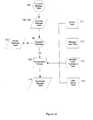
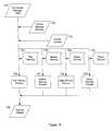
- FIG. 5is a flow chart depicting the operation of the system according to the invention.
- FIG. 6is a schematic of a local RF network linking several pieces of equipment together in accordance with an alternative embodiment of the invention.
- FIG. 7is a ladder logic diagram in accordance with the invention for an exemplary air conditioning unit.
- FIG. 8is a schematic of two types of data transport utilized by the invention.
- FIG. 9is a schematic of two Incoming Message Tables each respectively receiving information from the two data transports of FIG. 8 .
- FIG. 10is a logic chart illustrating the functioning of the normalization module of FIG. 4 .
- FIG. 11is a schematic of the various data tables of FIG. 10 .
- FIG. 12is a schematic of the Device Message Table, Delivery Table, and Device Location Table which are part of the relational data base of FIG. 4 .
- FIG. 13is a schematic of various tables which contain some of the information of the user-defined message profiles of the invention.
- FIG. 14is a schematic of various tables which contain information of outgoing messages of the invention.
- FIG. 15is a logic chart illustrating the sending out of messages from the system in accordance with the invention.
- FIG. 16is a schematic of the remote interface unit of FIG. 1 .
- Equipment that needs to be monitored frequentlypreferably operates within certain acceptable parameters. Some of these parameters are more crucial to the operation and/or life span of the equipment than are other parameters. For example, a low battery condition might be a lot less serious than a low coolant level condition. Whenever a piece of equipment operates outside its preferred parameters, an “exception” condition is created or said to exist. An exception condition can also be indicative of a regularly scheduled event occurring too often, too infrequently, or not at all. An exception condition could also be indicative of a measured value being beyond the design specification for the equipment.
- a monitored piece of equipmentWhen a monitored piece of equipment detects an exception condition, it activates its interface to the cellular phone network.
- the interfaceeffectively acts as a cell phone in a roaming condition.
- the interface“attempts” to make a telephone call; because it is not recognized as being a resident of the local cell, the local cell (via the cellular network or mobile switching center) contacts the “home cell” of the interface to insure that the interface is in good standing to complete the “call.”
- the local cellWhen the local cell is contacting the message routing service, it transmits the following information: the serial number of the interface; the multi-digit “phone number” assigned to the interface; and the multi-digit phone number that the interface is “attempting to call.”
- the message routing servicetells the local cell that the interface is okay and should not be blacklisted, that the call need not go through, and that the interface should be removed from the “okay to roam” list immediately.
- the interfaceis not really trying to call anyone; the multi-digit phone number it was trying to call represents a multi-digit code of information that is being sent to the message routing service and may represent fault information (e.g., 212-555-1212 means “filter needs cleaning”).
- the phone number assigned to the interface(which is also sent along with the phone number it is “trying to contact”) may not only indicates which unit is doing the transmitting but may also convey fault information, since many of the devices being monitored do not have a large number of different fault conditions.
- This type of technologyin which information is transmitted in the handshaking portion of a cellular transmitter communicating to a local cell, appears in U.S. Pat. No. 5,594,740 to LaDue and U.S. Pat. No.5,546,444 to Roach, Jr.
- the exception or status informationis embedded in the digits of the “phone number” the interface is allegedly calling (the “dialed digits”); in Roach, Jr. (the Bell South Cellemetry version), the exception or status information is embedded in the electronic serial number (ESN) of the interface, a number which identifies the physical hardware of the device.
- ESNelectronic serial number
- the information which identifies which interface has sent a messagemay be embedded in the mobile identification number (MIN) assigned to the interface unit.
- the ESNmay also contain interface identification information. The structure of the quanta or packets of information transmitted by typical data transports will be discussed in greater detail below.
- the present inventionexpands on this technology and includes the message delivery technique mentioned above.
- the Aeris or Bell South Cellemetry routertransmits the exception data to the inventive message delivery system which forwards the information to the contractor who is responsible for maintaining the faulty equipment.
- the contractoris provided with an account on the message delivery system that he can access via the Internet.
- the contractorsets up the specific parameters of which exception conditions are reported to which individuals.
- the contractoralso sets up by which media (fax, e-mail, PCS) these individuals are to be notified. Multiple individuals may be alerted as to a exception condition. All of this data constitutes the contractor's message profile.
- both the contractor and the owner of the premisesmight be signaled if there is a low/high refrigerant condition, however perhaps only one of them would be notified if a filter required cleaning.
- the usermay also set, as part of the message profile, that different messages be delivered to different individuals at different times of the day, week, month, season, or year. For example, a high priority exception message may be directed to one repair/maintenance entity during regular business hours but be directed to a different repair/maintenance entity at night. Similarly, the same person could be contacted by different means (e.g., fax or PCS) at different times.
- the content of the messagesmay also vary as a function of time.
- the various aspects of a user's message profileare stored in a plurality of look-up tables on a data base, as will be explained below.
- the interfacemay be programmed to check in once a day with an “all systems okay” message.
- This “okay” messagealso gets routed to the message delivery system.
- an exception message subroutine in the message delivery systemthe portion of the system which handles the above-mentioned fault messages—
- the “okay” messageis checked by a missing message subroutine.
- the missing message subroutinechecks the entire list of HVAC interfaces that are supposed to signal “okay” from the message delivery system database.
- the missing message subroutinecompares the entire list to the list of HVAC interfaces that actually checked in as “okay”.
- the message delivery systemsends out the appropriate messages to the proper individuals via the selected media, all in accordance with the user's message profile lodged in the user's account with the message delivery system.
- the periodic “okay” or status messageis not merely limited to providing a status “heartbeat” for the equipment but may also be employed to transmit information about the monitored piece of equipment.
- the status messageonly requires a portion of its digits to convey equipment identification information, thus allowing other information to be transmitted as well.
- the status messagemay include statistical information about the equipment such as how many cycles it has performed since the last message, the run time of the motor, etc.
- the status messagemay also serve as a reminder for routine maintenance, or it may report very minor or low-priority conditions that are not time sensitive.
- the format of the message sent from the failing device to the local cell to the router to the message delivery systemis a multi-digit code.
- the first digitcan be for message format (e.g., status message, exception message, etc.).
- the sub-addressis a digit or two reserved to identify to which unit that a transceiver interface is assigned is experiencing an exception condition; i.e., one transceiver interface may be assigned to a building having nine HVAC units, all connected to the transceiver via a bus line, or one interface may be part of a local RF network where each of multiple HVAC units has its own transmitter.
- the final digitswould indicate tie specific exception condition.
- incoming messages from different locationsmay have different structures or formats. Also, one would want the inventive system to be able to accommodate additional formats of transports as they are developed without having to rebuild the server every time. It is thus desirable to convert all of the incoming messages into a single normalized format for ease of subsequent manipulation.
- the multi-digit message received by the message delivery systemis normalized, converted into a regular text message, and forwarded to the user/contractor. Information can also include model, brand, installation date, and climate and weather data for the site. Alternatively, much of this type of equipment criteria can be stored at the central data base so that only the equipment identification information need be transmitted.
- a number of pieces of equipmentmay be linked to a single cellular interface via a local RF network. This is advantageous because many buildings have multiple pieces of HVAC equipment, and the provision of each piece with its own cellular interface is expensive. The deployment of a local RF network is also advantageous when the multiple HVAC units are fairly remote and a hardwired connection to a common bus line would be impractical or impossible.
- FIG. 1shows an overall view of the inventive system 50 .
- An existing piece of equipmentmay be monitored, for example; an air-conditioner 2 , boiler 3 , motor starter 4 , heater 5 , or any other piece of equipment they may be desired to be monitored.
- the existing piece of equipmentis fitted with an interface unit 10 .
- the interface unit 10sends to the message delivery server 1 a status signal to let the message delivery server 1 know that the equipment being monitored and the interface unit 10 are functioning correctly.
- the interface unit 10sends an incoming exception message to the message delivery server 1 .
- the message delivery server 1then routes the message as an outgoing exception message to the appropriate user interface; e-mail 6 , fax 7 , pager 8 , voice 9 , etc., according to the message profile as configured by the user of the system 21 via the Internet 122 .
- the inventive systemcan be deployed on existing pieces of remote equipment.
- Various sensorscan be added to an air conditioner, a boiler, etc. that can detect various conditions.
- different sensorscan be provided throughout the system each to detect a different condition such as low or high pressure, a condensate spill, air flow, fan motion, compressor function, etc.
- Any and all conventional sensorsare contemplated as being usable in the invention, including but not limited to pressure sensors, pitot tubes, motion sensors, photosensors, electrical resistance sensors, moisture sensors, magnetic sensors, and the like.
- the various sensors in a monitored piece of equipmentare preferably arranged in ladder logic configurations in programmable logic controllers (PLCs). Each sensor is responsible for detecting a certain condition or monitoring a certain parameter. These sensors can be grouped via Boolean logic operators (AND, OR, XOR, NOT, etc.) to provide the circumstances under which an exception condition is defined.
- PLCsprogrammable logic controllers
- FIG. 7An example of such a ladder logic PLC for a typical air conditioning unit is shown in FIG. 7 .
- Each of sensors 602 - 609monitors a different condition/parameter of the unit.
- Sensor 604detects low pressure in the coolant
- sensor 605detects high pressure in the coolant
- sensor 606detects if the fan is working
- sensor 607detects if the compressor is working
- sensor 608determines if a condensate spill has occurred
- sensor 609detects if the compressor is working.
- Some of the logicis direct and simple. For example, if sensor 605 detects a high pressure condition, high pressure message 101 is sent via the message generating mechanism of interface unit 10 . Similarly, if sensor 608 detects a condensate spill, message 102 is sent.
- the dip switchesare provided to allow certain portions of the logic to be disabled if a customer is not interested in receiving a certain type of message. For example, a sensor could be set to detect if a compressor is cycling fast and to send a “fast cycle” message in that event. However, if the user has the compressor deliberately set up to cycle fast, the user will not want to receive a constant stream of messages informing him that the compressor is cycling fast. Instead, a dip switch can be set to disable that message from being sent.
- the conventional dip switchis adjustable on-site. The invention contemplates also enabling the user to set up virtual dip switches via the Internet at a central server as will be explained below.
- Each PLCcan be different for each unit, type of unit, brand, model, etc.
- the PLCmay be hard wired at the remote installation site in the interface unit 10 , or software in the interface unit may simulate the workings of a PLC as a “virtual PLC.”.
- the various sensorscan be linked via computer software at a web site that interacts with system 21 , or a virtual PLC may be provided on server 1 . For example, instead of sending out a low pressure message 100 for a low pressure condition and a high pressure message 101 for a high pressure condition, a user can OR the outputs of sensors 604 and 605 together for the sending out of an “abnormal pressure” message.
- a usercan adjust a logic ladder in the same or similar fashion as one would edit a message profile, e.g., by menu-driven websites, by an automated telephone response system, etc.
- the usercan, of course, request an initial hardwired configuration of the system installer and have that adjusted on-site as needed.
- each piece of equipment 1 - 4is provided with its own interface unit 10 .
- An alternative configurationis shown in FIG. 6 .
- four air conditioners 2 A-Dare each provided with sensor 600 (which generically represents any of sensors 602 - 609 and any like sensors) and an RF transmitter 601 .
- sensor 600which generically represents any of sensors 602 - 609 and any like sensors
- transmitter 601transmits an RF signal 610 to a common interface unit 10 ′.
- Common interface unit 10 ′includes antenna A for receiving signals 610 .
- Unit 10 ′sends incoming messages to the electronic message delivery server 1 via link 11 in the same manner as shown in FIG. 1 .
- FIG. 2is a detailed view of link 11 shown in FIG. 1.
- a messageis transmitted from the cellular interface unit 10 a via a radio frequency link 13 to a nearby cellular transceiver site 14 , the message is then routed to the cellular network or mobile switching center (MSC, e.g., a cellular carrier such as Bell Atlantic) 16 where the message is then delivered via data circuits 17 and via router 51 (e.g., Bell South Cellemetry or Aeris) to the message delivery server 1 .
- MSCmobile switching center
- router 51e.g., Bell South Cellemetry or Aeris
- reference numerals 11 a and 11 brefer to different types of links. Specifically, link 11 a is for receiving incoming exception and status messages from interfaces 10 which are in regions wired for sending data via the dialed digits control channel; link 11 b forwards messages along the ESN channel to the message server 1 .
- FIGS. 3 a-dshow a more detailed view of the various outbound links 12 a-d that connect the server 1 to the various electronic media.
- server 1sends the message over a telephone line 18 a to the Internet 122 and deposits the message in the user's e-mail box 6 .
- server 1sends the message over a telephone line 18 b through the public telephone switched network (PTSN) 19 to the user's fax machine 7 .
- PTSNpublic telephone switched network
- server 1sends the message over a telephone line 18 c to the user's pager service 53 and thence to the user's pager or PCS 8 .
- server 1sends the message over a telephone line 18 d through the PTSN 19 to the user's voice mail box 9 .
- the same messagemay also be sent to a number of other devices as configured by the user 121 over the Internet 122 .
- the same message that is being sent to a fax machine 7 as described abovemay also simultaneously be sent to an e-mail 6 recipient via the Internet.
- different messagescan be sent to different individuals simultaneously for the same fault condition; for example, the owner of the premises may receive a less-detailed message than the contractor.
- a user's message profilecan also be configured to store messages on server 1 for delivery at a later time or after certain conditions are met. For example, a contractor may not want his beeper activated every time server 1 receives an incoming exception message.
- the user profilecan be configured to deliver messages on groups or only after several messages have accumulated for the same user/contractor.
- an outgoing exception messagemay be generated only after several of the same type of incoming message are received; a portion of the memory of server 1 may be devoted to the storing and/or accumulating of messages.
- a single outgoing exception messagemay be generated in response to several incoming messages.
- the usercan configure virtual dip switches to enable or disable certain error messages.
- Conventional hardwired dip switchesmust be adjusted on site at the remote equipment.
- Virtual dip switchesare software subroutines stored in server 1 which allow the user to toggle on or off certain portions of the ladder logic of the PLCs controlling the sensors of the remote equipment.
- the usercan go to a website on the Internet 122 and, through menu-driven commands, enable or disable sections of the ladder logic just as he would be able to by flipping conventional dip switches at the installation site of the remote equipment. Additionally, the user will be able to configure the logic of the PLC remotely via the Internet as well.
- a usermay also control the functioning of a remote device in this way, via the Internet.
- the usercan enter commands at the website or other Internet interface, and those commands are forwarded to the server 1 .
- a command messagemay be sent to the remote device through interface unit 10 .
- Such command messagesallow the user to activate, deactivate, and otherwise control the appliance.
- the interface unit 10can receive these command messages D because the means by which the unit 10 communicates with the server, e.g., the cellular telephone network, is bi-directional. As a result of this bi-directionality, incoming links 11 a-d may also be used to communicate with the devices through their respective interface units 10 .
- FIGS. 4 and 8 - 15show the details of the message delivery server 1 .
- server 1includes four hardware devices (separated by heavy lines) 200 , 300 , 400 , and 500 .
- Device 200is responsible for receiving incoming messages, processing them in accordance with the user's preferences, and routing them for output. Messages may be temporarily stored or accumulated on device 200 before being transmitted to the user if the user's message profile is set up accordingly.
- Device 300enables the user 121 to access server 1 and create or edit his message profile residing in relational data base 21 of device 200 .
- Device 400includes the various drivers 33 which are responsible for transmitting the various messages to the various media (fax, e-mail, etc.).
- Device 500includes billing computer 38 for keeping track of the charges and fees associated with the user's use of the service. It should be understood that the specific portions of each hardware device need not be arranged in the precise configuration shown.
- a relational data base 21At the core of server 1 is a relational data base 21 .
- Incoming messagesare received by a specific service designed to handle both the transport method and message formatting. Every interface unit 10 is provided, like a cellular telephone, with an electronic serial number (ESN, to identify the specific interface unit sending the message) and a mobile identification number (MIN, similar to a cellular telephone's phone number). In some instances, the exception or status information is embedded in the dialed digits the interface transmits.
- the dialed digits control channel module 25specifically receives messages that are encoded in the control channel's dialed digits (see U.S. Pat. No. 5,594,740).
- the ESN control channel module 24receives messages that are encode in the electronic serial number of the message (U.S. Pat. No.
- a dialed digits module 25and an ESN module 24 , because some geographic regions employ dialed digit data coding, while other regions employ ESN data coding.
- Informationmay be transmitted via the MIN of the interface 10 and also received by message delivery server 1 . Services are also available to receive messages for analog modems connected to the public telephone switched network 23 , and the cellular digital packet data network 22 . As additional methods of transmitting data become available, they can be added to the services layer.
- All incoming messagesare normalized at the normalization module 26 so that all incoming messages can then be processed without regard to their incoming medium. All incoming messages are passed to the normal message subroutine 27 , exception messages are passed on for processing and routing via the user's configuration through the data base 21 , and periodic status messages are queued.
- the missing message subroutine 28compares received status messages with a list of expected messages. Status messages that are not received have an error message generated by the missing message subroutine 28 which are then delivered as configured by the user in his message profile as recorded in the relational database 21 .
- Messages to be deliveredare placed in a message queue 32 ; as message traffic permits the appropriate drivers 33 request messages from the message queue 32 and route the messages over the appropriate transport. Numeric pages, faxes, voice and DTMF 34 are sent over the PTSN 12 b-d , e-mail 35 is sent over the Internet 122 .
- a driver 33has successfully delivered, a record is made in the data base 21 by the delivery confirmation subroutine 31 showing time and date of successful deliveries. Undeliverable messages are routed back to the database for generation of undeliverable message errors.
- Users 121connect to an Internet information server 30 via the Internet 122 .
- the Internet information serverpresents to the user the information pertaining to that user's interfaces. Requests to alter the user's data are passed through active server pages 29 to protect both the integrity and security of the data base 21 . All messages and transactions that pass through the system are logged in section 36 , the transaction and message logs are then interfaced by section 37 to a billing system 38 .
- a portion of the memory in relational data base 21is preferably used to compile data regarding the devices being monitored over time.
- datais sortable by any number of different criteria, including brand of equipment, specific models of equipment, installation date (and thus the age of the equipment), the general local climate in which the equipment is installed (e.g., arid, humid, warm, rainy, etc.), local weather conditions in a given period of time, and the like.
- This informationis usable in a number of different ways.
- a usercan log in via the Internet, for example, and find out the maintenance history of his specific units to see which are the most reliable or most unreliable. Alternatively, a user can check to see which brands or models generally are the most reliable for any given conditions (age, climate, weather, etc.).
- the informationmay be collated and processed by the operator of data base 21 and published by any number of different criteria. Any of the various messages may be stored for this purpose, e.g., the incoming messages from the interface units, the normalized messages output from the normalization module, the outgoing messages, normal status messages, etc.
- An example of the system's operation from the perspective of the user-contractoris as follows.
- a user-contractor 121first signs up with the system 50 , he receives an account on the electronic message delivery server 1 .
- the contractor 121is prompted through software to enter the pager numbers, cellular telephone numbers, facsimile machine numbers, and Internet addresses of any individuals who are to be contacted in the event of an exception condition in building equipment 2 - 5 for which the contractor is responsible.
- the user-contractor 121may also set the software to notify him of the periodic successful routine status check messages conveyed from equipment 2 - 5 .
- FIG. 5depicts a flow chart of the basic steps that occur when a message is received by server 1 .
- step S 1the message is received.
- step S 2normalization module 26 removes the required elements from the incoming message and arranges them in a normalized format and stores them as a record in a table.
- Server 1can now examine a specific element in a message of any received media type.
- step S 3it is determined what type of error message has been received. If it is an exception message that requires immediate action, it is passed onto a process to begin configuration of a readable message at step S 4 for delivery at step S 5 . If not, server 1 determines if the received message is a “unit checking in” or a “system ok” status message at step S 6 .
- a storing/accumulating stepmay occur between steps S 4 and S 5 .
- Undefined messagesare handled at step S 7 . If it is configured as a periodic message received to indicate normal operation of a unit, the message is stored at step S 8 for use at a later time. Periodically, the list of units that have reported in at step S 8 and the list of active units expected to report in (part of database 21 ) are compared at step S 9 . Units on the active list that do not appear on the checked-in units list are processed, and units that failed to report in have messages created at step S 10 . These messages are then posted for further processing and message delivery at step S 5 .
- boiler 3breaks down in a non-catastrophic manner.
- the fault conditionis detected by a sensor (not shown) and encoded to interface 10 .
- Interface 10transmits a radio message via link 13 to a local cell site 14 , which contacts data circuits 17 via cellular network 16 .
- Circuits 17forward the message to message server 1 . If the message is transmitted by the cellular telephone network 16 , the ESN arrives via link 11 b to ESN channel 24 ; alternatively, the dialed digits information arrives via link 11 a to dialed digits channel 25 .
- the messageis normalized in normalization module 26 and passed along to the normalized message process module 27 .
- Module 27selects the user's message profile from relational database 21 and in accordance therewith, determines what message gets sent to whom and by which medium. Alternatively or in addition, multiple fault conditions may be linked together via user-configurable ladder logic.
- FIG. 4shows data being received in a variety of formats via links 11 a-d by device 200 .
- FIG. 8illustrates two exemplary data transport formats receivable by device 200 .
- a message received from the first transport, “Transport A,”is received in the form of a string 700 of information packets having data packet 702 .
- Data packet 702is the message forwarded to the server by interface unit 10 .
- This particular transportdelivers the message in the form of fifteen decimal digits as shown by exemplary data packet 702 A.
- Transport BA different exemplary transport, “Transport B,” is shown in FIG. 8 below Transport A.
- Transport Ba single packet 701 is received.
- the single packetis parsed into elements which include a data element 703 .
- An exemplary data element 703 Ais shown to include eight hexadecimal digits.
- Transport Adelivering the data in the form of fifteen decimal digits
- Transport Bdelivering the data in the form of eight hexadecimal digits.
- relational data base 21On relational data base 21 , a number of tables are provided, at least one for each transport, into which the received data is deposited.
- FIG. 9shows the tables on data base 21 that are loaded with the data received from Transports A and B; Incoming Message Transport A Table 705 receives data elements 702 from Transport A, and Incoming Message Transport B Table 706 receives data elements 703 from Transport B.
- a standard data base commandis used to insert the data into the next available row in the appropriate table when a data message is received from a transport.
- the central data base 21may be provided with and use a conventional off-the-shelf data base processor such as SQL7 sold by Microsoft.
- FIG. 10shows the flow of data for a typical transport. All of the elements shown on FIG. 10 are required for each of the transports with the exception of the Normalized Message Table 710 , which is the common table that all received exception messages are deposited into for further processing.
- the particular interface to a transportis represented generally as device 200 , which includes the aforementioned control channels 22 - 25 .
- Device 200places the next incoming message from the transport into the corresponding Incoming Message Table 708 by utilizing the database's add row function.
- the Incoming Message Table 708maintains the history of all messages received from a transport. When a row is added to the Incoming Message Table 708 , the system determines at Step S 3 (also see FIG.
- the Normalization Process 709references a group of data tables 711 - 714 to validate the received message and translate the exception message from its original format that was best suited for the transport.
- Data tables 711 - 714are provided on data base 21 .
- Each transportrequires its own set of data tables. For example, as shown in FIG. 11, tables 711 A- 714 A correspond to Transport A; similar tables (not shown) would be provided for Transport B and any other transports utilized by the system.
- the Normalized Message Table 710is a single table to which the respective Normalization Processes of all transports adds a row.
- the Normalization Processis the logical equivalent of normalization module 26 and normal message subroutine 27 of FIG. 4 .
- FIG. 15shows the flow of data after a message is deposited into the message queue 32 (see FIG. 4) pending delivery.
- the Normalized Message Table 710functions as this queue.
- a look-up operationis performed in the Device Message Delivery Table 720 (shown in detail in FIG. 12) for all message deliveries that pertain to the exception message pending delivery.
- Device Message Delivery Table 720is a table of all delivery methods for all outgoing messages that potentially can be sent. Details of the Device Message Delivery Table 720 A contains the information on, how many delivery attempts should be made for a particular message, by what method the delivery should be made, how many times this attempt should be made, how long to wait between attempts, and during what periods of time a message should be sent.
- Each delivery methodi.e. Fax Delivery, Modem Delivery, Pager Delivery, Phone Delivery, etc. has a corresponding delivery process 730 - 733 and message table 722 - 725 .
- the Fax Delivery process 730contains the required hardware and software to interface to the Public Switched Telephone Network (PSTN) and send a fax transmission to fax equipped receiver.
- the Fax Delivery table 722contains the actual message to be sent to a fax receiver for each potential fax message.
- Each delivery processadds a row to the Delivery Attempt table 726 with the result of a delivery attempt. A successful or failed fax delivery is indicated in the table by the addition of a row by the result returned from, the fax hardware interface indicating the delivery result.
- the telephone delivery processutilizes a text to speech synthesizer to speak the message text to the person who answers the telephone call. Confirmation of deliver is established by the system requesting the person who is receiving the message to make certain actions such as press certain buttons on a touch tone telephone to acknowledge the receipt of the message. Acknowledgment or not is recorded by the Phone Delivery process 733 in the Delivery Attempt table 726 .
- the previously described user-defined message profileis not a discrete set of instructions that are all stored together, although it would appear so from the user interface, e.g., the website maintained by server 30 . Rather, a user's message profile includes multiple elements, each of which is placed on a different table according to the type of data it represents. All of the users' respective delivery instructions are stored on Device Message Delivery Table 720 . All of the users' respective facsimile delivery instructions are stored on Fax Delivery Table 722 . All of the users' respective pager delivery instructions are stored on table 724 . Each entry is identifiable by the “Key” associated therewith, as shown in the various tables of FIGS. 12-14.
- the data engine(e.g., SQL 7) selects the next available row in the Normalized Message Table 710 . Utilizing the Message Delivery ID, it then selects all records with the same Message Delivery ID in the Device Message Delivery Table 720 . The resulting selection list is sorted by Delivery Method and those records that meet the selection criteria for message delivery time, and in service are prepared for message delivery. Each delivery process 730 - 733 polls the data engine to see if a message is available for delivery in the Device Message Delivery Table 720 with a delivery method that is suitable for its delivery function.
- the fax delivery process 730will select the corresponding user defined message for the exception message to be sent from the Fax Delivery Table 722 along with the equipment location, make model, and serial number found in the Device Location Table 721 . The delivery process then attempts to send the message to the user defined address found in the delivery table, for example, the fax number found in Fax Delivery table 722 .
- Each deliverable messageis configurable by the user simply by editing the message text found in the delivery tables 722 - 725 .
- Multiple deliveriesare accomplished by having multiple delivery records in the delivery tables 722 - 725 with the same Message Delivery ID each having a unique delivery address i.e. fax number, phone number, etc. Additional delivery methods are easily added to the system by adding a new delivery transport process and an associated delivery table.
- FIG. 16illustrates the remote interface unit (RIU) 10 used to send messages to the remote server.
- the RIUcontains a removable module capable of sending messages to the server over a specific transport shown here as a two way radio 801 .
- the RIU 10can be connected to a monitored piece of equipment in several ways. An array of inputs 808 can be wired into the monitored piece of equipment's limit, operating and auxiliary sensors. Alternatively or in addition, the RIU 10 can be connected to the monitored equipment's communication interface if equipped by the equipment manufacture via a serial interface 807 or 812 .
- the central processing unit (CPU) 804is preferably an industry standard 8-bit micro-controller with 3 general purpose input/output (IO) ports and 2 serial ports.
- the first IO portis connected to a display 800 that is used to indicate operating modes and conditions of the RIU 10 to a person installing, testing, or servicing the RIU.
- the second portis in communication with both the monitored equipment and the RIU's power supply.
- This port of the CPUis buffered and protected by filter 809 which uses standard filter arrangements from unwanted surges and voltage transients that may be present on the sensing devices 808 connected to the RIU.
- the portis also in communication with the RIU's internal power supply 803 .
- CPU 804is capable of operating the power supply 803 on and off in order to perform standby battery 802 tests, monitor the presence of line power, and use the frequency of the line power to maintain a time standard.
- the third IO portis used to connect additional memory 810 to the CPU 804 and to operate output drivers 813 , which are typically in the form of relays. The state of the outputs can either be determined by results of decisions made within the CPU 804 or commands received from the remote server via the transport radio 801 .
- the CPUhas two serial interface ports, the first port is connected to a multiplexer 805 that is used to steer the flow of serial data either to the transport radio module 801 or an internal interface 814 used to configure the RIR during manufacturing, testing, and subsequent configuration changes.
- the transport radio module 801is connected to the multiplexer 805 via a connector 815 ; this enables different radio transports to be installed at the manufacture to enable the use of a particular transport best suited for an application. Factors that may effect the transport selection are quantity of data to be sent to the remote server, and wireless networks deployed i.e. control channel over AMP, or CDPD.
- the second serial interfaceis connected in parallel to both an RS-232 driver 806 and a RS-485 driver 811 , with the respective driver being connected to an interface device, RS-232 807 and RS-485 812 .
- Different equipment manufacturesuse different interface schemes on their equipment, some use RS-232 and some RS-485. For that reason, the RIU supports both. When one of these interfaces is used to communicate with a piece of equipment's communication port, all internal data maintained by the equipment's internal CPU may be available to the RIU for transmission to the remote sever.
- Sensing devices 808may also be connected to the CPU 804 via the input protection circuit 809 when the RS-232 807 or RS-485 812 are used to communicate with the monitored equipment. Together, CPU 804 , multiplexer 805 , and radio 801 make up the message generating mechanism of interface unit 10 discussed above.
- the CPUassembles a packet (heartbeat) of data which contains status and operational data of connected monitored equipment and communicates this packet of data to the transport radio module 801 .
- the transport radio module 801then transmits the information to the remote server as a normal status message as explained above.
- the CPU 804also monitors the status of the sensing devices 808 . The state of these inputs is feed into a virtual Programmable Logic Controller (v-PLC) running within the CPU 804 .
- v-PLCvirtual Programmable Logic Controller
- the resultant relay outputs of the v-PLCcan cause the CPU 804 to assemble an exception message packet and pass it on to the transport radio 801 for delivery to the remote server.
- the inventionis not limited to the above description but rather is defined by the claims appearing hereinbelow. Modifications to the above description that include that which is known in the art are well within the scope of the contemplated invention.
- the inventionis designed to be adaptable to all forms of electronic communication, be they cellular telephone, land line telephone, electronic mail, facsimile, text page, voice mail, etc. All forms of electronic media are contemplated as being within the scope of the invention.
- multiple formats of incoming and outgoing messagesare contemplated as included within the scope of the claims and the invention. The user can adjust the format and content of the messages he receives by setting up his message profile accordingly.
- the inventionis also not limited to use in monitoring HVAC equipment but is contemplated to be useful for maintaining all forms of remote equipment.
- the inventive system and methodwould prove extremely expedient is monitoring and replacing warning lights on cellular towers, radio transmitter towers, and other remote structures.
Landscapes
- Engineering & Computer Science (AREA)
- General Engineering & Computer Science (AREA)
- Theoretical Computer Science (AREA)
- Physics & Mathematics (AREA)
- General Physics & Mathematics (AREA)
- Mechanical Engineering (AREA)
- Combustion & Propulsion (AREA)
- Chemical & Material Sciences (AREA)
- Signal Processing (AREA)
- Quality & Reliability (AREA)
- Business, Economics & Management (AREA)
- Emergency Management (AREA)
- Human Computer Interaction (AREA)
- Public Health (AREA)
- Health & Medical Sciences (AREA)
- Automation & Control Theory (AREA)
- Computer Networks & Wireless Communication (AREA)
- Computer Hardware Design (AREA)
- Telephonic Communication Services (AREA)
Abstract
Description
Claims (21)
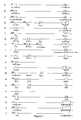
Priority Applications (2)
| Application Number | Priority Date | Filing Date | Title |
|---|---|---|---|
| US10/224,243US6717513B1 (en) | 1999-01-09 | 2002-08-19 | Electronic message delivery system utilizable in the monitoring of remote equipment and method of same |
| US10/662,940US20040095237A1 (en) | 1999-01-09 | 2003-09-16 | Electronic message delivery system utilizable in the monitoring and control of remote equipment and method of same |
Applications Claiming Priority (6)
| Application Number | Priority Date | Filing Date | Title |
|---|---|---|---|
| US11530599P | 1999-01-09 | 1999-01-09 | |
| US09/317,235US6147601A (en) | 1999-01-09 | 1999-05-24 | Electronic message delivery system utilizable in the monitoring of remote equipment and method of same |
| US09/401,460US6160477A (en) | 1999-01-09 | 1999-09-22 | Electronic message delivery system utilizable in the monitoring of remote equipment and method of same |
| US09/433,767US6211782B1 (en) | 1999-01-09 | 1999-11-03 | Electronic message delivery system utilizable in the monitoring of remote equipment and method of same |
| US09/578,137US6437691B1 (en) | 1999-01-09 | 2000-05-24 | Electronic message delivery system utilizable in the monitoring of remote equipment and method of same |
| US10/224,243US6717513B1 (en) | 1999-01-09 | 2002-08-19 | Electronic message delivery system utilizable in the monitoring of remote equipment and method of same |
Related Parent Applications (1)
| Application Number | Title | Priority Date | Filing Date |
|---|---|---|---|
| US09/578,137ContinuationUS6437691B1 (en) | 1999-01-09 | 2000-05-24 | Electronic message delivery system utilizable in the monitoring of remote equipment and method of same |
Related Child Applications (1)
| Application Number | Title | Priority Date | Filing Date |
|---|---|---|---|
| US10/662,940Continuation-In-PartUS20040095237A1 (en) | 1999-01-09 | 2003-09-16 | Electronic message delivery system utilizable in the monitoring and control of remote equipment and method of same |
Publications (1)
| Publication Number | Publication Date |
|---|---|
| US6717513B1true US6717513B1 (en) | 2004-04-06 |
Family
ID=27502137
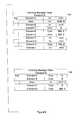
Family Applications (4)
| Application Number | Title | Priority Date | Filing Date |
|---|---|---|---|
| US09/578,137Expired - LifetimeUS6437691B1 (en) | 1999-01-09 | 2000-05-24 | Electronic message delivery system utilizable in the monitoring of remote equipment and method of same |
| US09/932,552Expired - LifetimeUS6462654B1 (en) | 1999-01-09 | 2001-08-17 | Electronic message delivery system utilizable in the monitoring of remote equipment and method of same |
| US10/093,589Expired - LifetimeUS6535123B2 (en) | 1999-01-09 | 2002-03-08 | Electronic message delivery system |
| US10/224,243Expired - LifetimeUS6717513B1 (en) | 1999-01-09 | 2002-08-19 | Electronic message delivery system utilizable in the monitoring of remote equipment and method of same |
Family Applications Before (3)
| Application Number | Title | Priority Date | Filing Date |
|---|---|---|---|
| US09/578,137Expired - LifetimeUS6437691B1 (en) | 1999-01-09 | 2000-05-24 | Electronic message delivery system utilizable in the monitoring of remote equipment and method of same |
| US09/932,552Expired - LifetimeUS6462654B1 (en) | 1999-01-09 | 2001-08-17 | Electronic message delivery system utilizable in the monitoring of remote equipment and method of same |
| US10/093,589Expired - LifetimeUS6535123B2 (en) | 1999-01-09 | 2002-03-08 | Electronic message delivery system |
Country Status (3)
| Country | Link |
|---|---|
| US (4) | US6437691B1 (en) |
| AU (1) | AU5289100A (en) |
| WO (1) | WO2000072285A1 (en) |
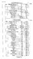
Cited By (149)
| Publication number | Priority date | Publication date | Assignee | Title |
|---|---|---|---|---|
| US20020022894A1 (en)* | 2000-05-23 | 2002-02-21 | Evren Eryurek | Enhanced fieldbus device alerts in a process control system |
| US20020055790A1 (en)* | 2000-11-07 | 2002-05-09 | Havekost Robert B. | Enhanced device alarms in a process control system |
| US20020077711A1 (en)* | 1999-02-22 | 2002-06-20 | Nixon Mark J. | Fusion of process performance monitoring with process equipment monitoring and control |
| US20020138578A1 (en)* | 2001-01-24 | 2002-09-26 | Qiaofeng Zhou | Using virtual network address information during communications |
| US20030028268A1 (en)* | 2001-03-01 | 2003-02-06 | Evren Eryurek | Data sharing in a process plant |
| US20030055952A1 (en)* | 2001-09-17 | 2003-03-20 | Ricoh Company, Ltd | System, method, and computer program product for transferring remote device support data to a monitor using e-mail |
| US20030065776A1 (en)* | 2001-09-28 | 2003-04-03 | Dale Malik | Methods and systems for a communications and information resource manager |
| US20030074434A1 (en)* | 2001-10-11 | 2003-04-17 | Jason James L. | Determination of message source in network communications |
| US20040083456A1 (en)* | 2002-06-03 | 2004-04-29 | James Cornett | Wizard for programming an intelligent module |
| US20040155757A1 (en)* | 2003-02-11 | 2004-08-12 | Litwin Louis Robert | Apparatus and method for monitoring security camera operation over a powerline network |
| US20040246120A1 (en)* | 2003-06-04 | 2004-12-09 | Benner Bradley A. | Alert processing |
| US20050012608A1 (en)* | 2000-11-07 | 2005-01-20 | Havekost Robert B. | Integrated alarm display in a process control network |
| US20050076338A1 (en)* | 2001-09-28 | 2005-04-07 | Malik Dale W. | Communications and information resource manager |
| US6886039B1 (en)* | 1999-11-12 | 2005-04-26 | Hitachi, Ltd. | Adaptive communication method |
| US20050146430A1 (en)* | 2003-12-31 | 2005-07-07 | Adamo Patrick | Security messaging system |
| US20050267701A1 (en)* | 2002-01-07 | 2005-12-01 | Siemens Energy & Automation, Inc. | Systems, methods, and devices for generating variable-frequency pulses |
| EP1610069A1 (en)* | 2004-06-24 | 2005-12-28 | LG Electronics Inc. | Air conditioning system and method for controlling the same |
| US20060022817A1 (en)* | 2001-05-24 | 2006-02-02 | Merrell Daniel B | Alarm systems, alarm system operating methods, and alarm extension devices |
| US7007085B1 (en)* | 2001-09-28 | 2006-02-28 | Bellsouth Intellectual Property Corporation | Message log for wireline, voice mail, email, fax, pager, instant messages and chat |
| US20060100777A1 (en)* | 2004-11-05 | 2006-05-11 | Houston Staton | Method and system to configure and utilize geographical zones |
| US20060099971A1 (en)* | 2004-11-05 | 2006-05-11 | Houston Staton | Method and system to monitor and control devices utilizing wireless media |
| US20060099969A1 (en)* | 2004-11-05 | 2006-05-11 | Houston Staton | Method and system to monitor persons utilizing wireless media |
| US7092794B1 (en)* | 2000-10-05 | 2006-08-15 | Carrier Corporation | Method and apparatus for connecting to HVAC device |
| US20060234726A1 (en)* | 2005-04-13 | 2006-10-19 | Wirelesswerx International, Inc. | Method and System for Initiating and Handling an Emergency Call Utilizing Geographical Zones |
| US20060233318A1 (en)* | 2005-04-13 | 2006-10-19 | Wirelesswerx International, Inc. | Method and System for Providing Location Updates |
| US20060234727A1 (en)* | 2005-04-13 | 2006-10-19 | Wirelesswerx International, Inc. | Method and System for Initiating and Handling an Emergency Call |
| US20070030145A1 (en)* | 2005-08-03 | 2007-02-08 | Marcichow Martin E | Networking of discrete plumbing devices |
| US7221988B2 (en) | 2001-03-01 | 2007-05-22 | Rosemount, Inc. | Creation and display of indices within a process plant |
| US20070115108A1 (en)* | 2005-11-23 | 2007-05-24 | Honeywell International, Inc. | Security system status notification device and method |
| US20070157018A1 (en)* | 2005-12-30 | 2007-07-05 | Honeywell International, Inc. | Method and apparatus for using SMS short code messaging to facilitate the transmission of a status update for a security system |
| US7272531B2 (en) | 2005-09-20 | 2007-09-18 | Fisher-Rosemount Systems, Inc. | Aggregation of asset use indices within a process plant |
| US7274973B2 (en) | 2003-12-08 | 2007-09-25 | Invisible Service Technicians, Llc | HVAC/R monitoring apparatus and method |
| US20080129497A1 (en)* | 2003-09-11 | 2008-06-05 | Jon Woodard | Reconfigurable alarm apparatus |
| US20080129184A1 (en)* | 2006-12-05 | 2008-06-05 | Semiconductor Energy Laboratory Co., Ltd. | Plasma display panel and field emission display |
| US20080220720A1 (en)* | 2004-11-05 | 2008-09-11 | Wirelesswerx International, Inc. | Method and system for providing area specific messaging |
| US20090119142A1 (en)* | 2007-11-05 | 2009-05-07 | Sloan Valve Company | Restroom convenience center |
| US20090132163A1 (en)* | 2007-08-30 | 2009-05-21 | Wirelesswerx International, Inc. | Configuring and using multi-dimensional zones |
| US20090138336A1 (en)* | 2007-08-30 | 2009-05-28 | Wirelesswerx International, Inc. | Messaging in a multi-dimensional space |
| US20090137255A1 (en)* | 2007-08-30 | 2009-05-28 | Wirelesswerx International, Inc. | Mapping in a multi-dimensional space |
| US7557702B2 (en) | 1999-02-22 | 2009-07-07 | Evren Eryurek | Integrated alert generation in a process plant |
| US7702401B2 (en) | 2007-09-05 | 2010-04-20 | Fisher-Rosemount Systems, Inc. | System for preserving and displaying process control data associated with an abnormal situation |
| US20100138348A1 (en)* | 2009-06-12 | 2010-06-03 | Microsoft Corporation | Providing resource-related information using a standardized format |
| US20100318376A1 (en)* | 2009-06-12 | 2010-12-16 | Microsoft Corporation | Message-passing protocol between entities having dissimilar capabilities |
| US7937370B2 (en) | 2000-09-22 | 2011-05-03 | Axeda Corporation | Retrieving data from a server |
| EP2267993A3 (en)* | 2004-11-05 | 2011-05-18 | Wirelesswerx International, Inc. | Configuration and utilization of geographical zones to monitor and control movable entities |
| US7966418B2 (en) | 2003-02-21 | 2011-06-21 | Axeda Corporation | Establishing a virtual tunnel between two computer programs |
| US8005647B2 (en) | 2005-04-08 | 2011-08-23 | Rosemount, Inc. | Method and apparatus for monitoring and performing corrective measures in a process plant using monitoring data with corrective measures data |
| US20110205050A1 (en)* | 2010-02-23 | 2011-08-25 | Richard Pineau | Methods and systems for remote management of security systems |
| US8055758B2 (en) | 2000-07-28 | 2011-11-08 | Axeda Corporation | Reporting the state of an apparatus to a remote computer |
| US8055479B2 (en) | 2007-10-10 | 2011-11-08 | Fisher-Rosemount Systems, Inc. | Simplified algorithm for abnormal situation prevention in load following applications including plugged line diagnostics in a dynamic process |
| US8060886B2 (en) | 2002-04-17 | 2011-11-15 | Axeda Corporation | XML scripting of SOAP commands |
| USD648641S1 (en) | 2009-10-21 | 2011-11-15 | Lennox Industries Inc. | Thin cover plate for an electronic system controller |
| USD648642S1 (en) | 2009-10-21 | 2011-11-15 | Lennox Industries Inc. | Thin cover plate for an electronic system controller |
| US8065397B2 (en) | 2006-12-26 | 2011-11-22 | Axeda Acquisition Corporation | Managing configurations of distributed devices |
| US8073967B2 (en) | 2002-04-15 | 2011-12-06 | Fisher-Rosemount Systems, Inc. | Web services-based communications for use with process control systems |
| US8108543B2 (en) | 2000-09-22 | 2012-01-31 | Axeda Corporation | Retrieving data from a server |
| US8200186B2 (en) | 2007-08-30 | 2012-06-12 | Wirelesswerx International, Inc. | Emergency control in a multi-dimensional space |
| US8239066B2 (en) | 2008-10-27 | 2012-08-07 | Lennox Industries Inc. | System and method of use for a user interface dashboard of a heating, ventilation and air conditioning network |
| US8255086B2 (en) | 2008-10-27 | 2012-08-28 | Lennox Industries Inc. | System recovery in a heating, ventilation and air conditioning network |
| US8260444B2 (en) | 2010-02-17 | 2012-09-04 | Lennox Industries Inc. | Auxiliary controller of a HVAC system |
| US8295981B2 (en) | 2008-10-27 | 2012-10-23 | Lennox Industries Inc. | Device commissioning in a heating, ventilation and air conditioning network |
| US8301676B2 (en) | 2007-08-23 | 2012-10-30 | Fisher-Rosemount Systems, Inc. | Field device with capability of calculating digital filter coefficients |
| US8352080B2 (en) | 2008-10-27 | 2013-01-08 | Lennox Industries Inc. | Communication protocol system and method for a distributed-architecture heating, ventilation and air conditioning network |
| US8352081B2 (en) | 2008-10-27 | 2013-01-08 | Lennox Industries Inc. | Communication protocol system and method for a distributed-architecture heating, ventilation and air conditioning network |
| US8370479B2 (en) | 2006-10-03 | 2013-02-05 | Axeda Acquisition Corporation | System and method for dynamically grouping devices based on present device conditions |
| US8406119B2 (en) | 2001-12-20 | 2013-03-26 | Axeda Acquisition Corporation | Adaptive device-initiated polling |
| US8417595B2 (en) | 2001-03-01 | 2013-04-09 | Fisher-Rosemount Systems, Inc. | Economic calculations in a process control system |
| US8433446B2 (en) | 2008-10-27 | 2013-04-30 | Lennox Industries, Inc. | Alarm and diagnostics system and method for a distributed-architecture heating, ventilation and air conditioning network |
| US8437877B2 (en) | 2008-10-27 | 2013-05-07 | Lennox Industries Inc. | System recovery in a heating, ventilation and air conditioning network |
| US8437878B2 (en) | 2008-10-27 | 2013-05-07 | Lennox Industries Inc. | Alarm and diagnostics system and method for a distributed architecture heating, ventilation and air conditioning network |
| US8442693B2 (en) | 2008-10-27 | 2013-05-14 | Lennox Industries, Inc. | System and method of use for a user interface dashboard of a heating, ventilation and air conditioning network |
| US8452456B2 (en) | 2008-10-27 | 2013-05-28 | Lennox Industries Inc. | System and method of use for a user interface dashboard of a heating, ventilation and air conditioning network |
| US8452906B2 (en) | 2008-10-27 | 2013-05-28 | Lennox Industries, Inc. | Communication protocol system and method for a distributed-architecture heating, ventilation and air conditioning network |
| US8463443B2 (en) | 2008-10-27 | 2013-06-11 | Lennox Industries, Inc. | Memory recovery scheme and data structure in a heating, ventilation and air conditioning network |
| US8463442B2 (en) | 2008-10-27 | 2013-06-11 | Lennox Industries, Inc. | Alarm and diagnostics system and method for a distributed architecture heating, ventilation and air conditioning network |
| US8478861B2 (en) | 2007-07-06 | 2013-07-02 | Axeda Acquisition Corp. | Managing distributed devices with limited connectivity |
| US8543243B2 (en) | 2008-10-27 | 2013-09-24 | Lennox Industries, Inc. | System and method of use for a user interface dashboard of a heating, ventilation and air conditioning network |
| US8548630B2 (en) | 2008-10-27 | 2013-10-01 | Lennox Industries, Inc. | Alarm and diagnostics system and method for a distributed-architecture heating, ventilation and air conditioning network |
| US8560125B2 (en) | 2008-10-27 | 2013-10-15 | Lennox Industries | Communication protocol system and method for a distributed-architecture heating, ventilation and air conditioning network |
| US8564400B2 (en) | 2008-10-27 | 2013-10-22 | Lennox Industries, Inc. | Communication protocol system and method for a distributed-architecture heating, ventilation and air conditioning network |
| US8600558B2 (en) | 2008-10-27 | 2013-12-03 | Lennox Industries Inc. | System recovery in a heating, ventilation and air conditioning network |
| US8600559B2 (en) | 2008-10-27 | 2013-12-03 | Lennox Industries Inc. | Method of controlling equipment in a heating, ventilation and air conditioning network |
| US8612278B1 (en) | 2013-03-06 | 2013-12-17 | Wirelesswerx International, Inc. | Controlling queuing in a defined location |
| US8615326B2 (en) | 2008-10-27 | 2013-12-24 | Lennox Industries Inc. | System and method of use for a user interface dashboard of a heating, ventilation and air conditioning network |
| US8655490B2 (en) | 2008-10-27 | 2014-02-18 | Lennox Industries, Inc. | System and method of use for a user interface dashboard of a heating, ventilation and air conditioning network |
| US8655491B2 (en) | 2008-10-27 | 2014-02-18 | Lennox Industries Inc. | Alarm and diagnostics system and method for a distributed architecture heating, ventilation and air conditioning network |
| US8661165B2 (en) | 2008-10-27 | 2014-02-25 | Lennox Industries, Inc. | Device abstraction system and method for a distributed architecture heating, ventilation and air conditioning system |
| US8694164B2 (en) | 2008-10-27 | 2014-04-08 | Lennox Industries, Inc. | Interactive user guidance interface for a heating, ventilation and air conditioning system |
| US8725298B2 (en) | 2008-10-27 | 2014-05-13 | Lennox Industries, Inc. | Alarm and diagnostics system and method for a distributed architecture heating, ventilation and conditioning network |
| US8744629B2 (en) | 2008-10-27 | 2014-06-03 | Lennox Industries Inc. | System and method of use for a user interface dashboard of a heating, ventilation and air conditioning network |
| US8762666B2 (en) | 2008-10-27 | 2014-06-24 | Lennox Industries, Inc. | Backup and restoration of operation control data in a heating, ventilation and air conditioning network |
| US8774210B2 (en) | 2008-10-27 | 2014-07-08 | Lennox Industries, Inc. | Communication protocol system and method for a distributed-architecture heating, ventilation and air conditioning network |
| US8788100B2 (en) | 2008-10-27 | 2014-07-22 | Lennox Industries Inc. | System and method for zoning a distributed-architecture heating, ventilation and air conditioning network |
| US8798796B2 (en) | 2008-10-27 | 2014-08-05 | Lennox Industries Inc. | General control techniques in a heating, ventilation and air conditioning network |
| US8802981B2 (en) | 2008-10-27 | 2014-08-12 | Lennox Industries Inc. | Flush wall mount thermostat and in-set mounting plate for a heating, ventilation and air conditioning system |
| US8855825B2 (en) | 2008-10-27 | 2014-10-07 | Lennox Industries Inc. | Device abstraction system and method for a distributed-architecture heating, ventilation and air conditioning system |
| US20140316585A1 (en)* | 2013-04-18 | 2014-10-23 | Robert Bosch Gmbh | Remote maintenance |
| US8874815B2 (en) | 2008-10-27 | 2014-10-28 | Lennox Industries, Inc. | Communication protocol system and method for a distributed architecture heating, ventilation and air conditioning network |
| US8892797B2 (en) | 2008-10-27 | 2014-11-18 | Lennox Industries Inc. | Communication protocol system and method for a distributed-architecture heating, ventilation and air conditioning network |
| US20140372104A1 (en)* | 2012-08-30 | 2014-12-18 | Arria Data2Text Limited | Method and apparatus for situational analysis text generation |
| US8964338B2 (en) | 2012-01-11 | 2015-02-24 | Emerson Climate Technologies, Inc. | System and method for compressor motor protection |
| US8977794B2 (en) | 2008-10-27 | 2015-03-10 | Lennox Industries, Inc. | Communication protocol system and method for a distributed-architecture heating, ventilation and air conditioning network |
| US8974573B2 (en) | 2004-08-11 | 2015-03-10 | Emerson Climate Technologies, Inc. | Method and apparatus for monitoring a refrigeration-cycle system |
| US8994539B2 (en) | 2008-10-27 | 2015-03-31 | Lennox Industries, Inc. | Alarm and diagnostics system and method for a distributed-architecture heating, ventilation and air conditioning network |
| US9121407B2 (en) | 2004-04-27 | 2015-09-01 | Emerson Climate Technologies, Inc. | Compressor diagnostic and protection system and method |
| US9140728B2 (en) | 2007-11-02 | 2015-09-22 | Emerson Climate Technologies, Inc. | Compressor sensor module |
| US9152155B2 (en) | 2008-10-27 | 2015-10-06 | Lennox Industries Inc. | Device abstraction system and method for a distributed-architecture heating, ventilation and air conditioning system |
| US20150302414A1 (en)* | 2013-03-15 | 2015-10-22 | Emerson Electric Co. | Contractor dispatch service |
| US9183735B1 (en) | 2010-02-23 | 2015-11-10 | Oncam Global, Inc. | Methods and systems for remote management of security systems |
| US9201420B2 (en) | 2005-04-08 | 2015-12-01 | Rosemount, Inc. | Method and apparatus for performing a function in a process plant using monitoring data with criticality evaluation data |
| US9261888B2 (en) | 2008-10-27 | 2016-02-16 | Lennox Industries Inc. | System and method of use for a user interface dashboard of a heating, ventilation and air conditioning network |
| US9268345B2 (en) | 2008-10-27 | 2016-02-23 | Lennox Industries Inc. | System and method of use for a user interface dashboard of a heating, ventilation and air conditioning network |
| US9285802B2 (en) | 2011-02-28 | 2016-03-15 | Emerson Electric Co. | Residential solutions HVAC monitoring and diagnosis |
| US9310439B2 (en) | 2012-09-25 | 2016-04-12 | Emerson Climate Technologies, Inc. | Compressor having a control and diagnostic module |
| US9310094B2 (en) | 2007-07-30 | 2016-04-12 | Emerson Climate Technologies, Inc. | Portable method and apparatus for monitoring refrigerant-cycle systems |
| US9325517B2 (en) | 2008-10-27 | 2016-04-26 | Lennox Industries Inc. | Device abstraction system and method for a distributed-architecture heating, ventilation and air conditioning system |
| US9377768B2 (en) | 2008-10-27 | 2016-06-28 | Lennox Industries Inc. | Memory recovery scheme and data structure in a heating, ventilation and air conditioning network |
| US9405448B2 (en) | 2012-08-30 | 2016-08-02 | Arria Data2Text Limited | Method and apparatus for annotating a graphical output |
| US9432208B2 (en) | 2008-10-27 | 2016-08-30 | Lennox Industries Inc. | Device abstraction system and method for a distributed architecture heating, ventilation and air conditioning system |
| US9551504B2 (en) | 2013-03-15 | 2017-01-24 | Emerson Electric Co. | HVAC system remote monitoring and diagnosis |
| US9632490B2 (en) | 2008-10-27 | 2017-04-25 | Lennox Industries Inc. | System and method for zoning a distributed architecture heating, ventilation and air conditioning network |
| US9638436B2 (en) | 2013-03-15 | 2017-05-02 | Emerson Electric Co. | HVAC system remote monitoring and diagnosis |
| US9651925B2 (en) | 2008-10-27 | 2017-05-16 | Lennox Industries Inc. | System and method for zoning a distributed-architecture heating, ventilation and air conditioning network |
| US9678486B2 (en) | 2008-10-27 | 2017-06-13 | Lennox Industries Inc. | Device abstraction system and method for a distributed-architecture heating, ventilation and air conditioning system |
| US9765979B2 (en) | 2013-04-05 | 2017-09-19 | Emerson Climate Technologies, Inc. | Heat-pump system with refrigerant charge diagnostics |
| US9803902B2 (en) | 2013-03-15 | 2017-10-31 | Emerson Climate Technologies, Inc. | System for refrigerant charge verification using two condenser coil temperatures |
| US9823632B2 (en) | 2006-09-07 | 2017-11-21 | Emerson Climate Technologies, Inc. | Compressor data module |
| US9830672B2 (en)* | 2014-10-29 | 2017-11-28 | Solarcity Corporation | Power management message bus system |
| US9885507B2 (en) | 2006-07-19 | 2018-02-06 | Emerson Climate Technologies, Inc. | Protection and diagnostic module for a refrigeration system |
| US9927788B2 (en) | 2011-05-19 | 2018-03-27 | Fisher-Rosemount Systems, Inc. | Software lockout coordination between a process control system and an asset management system |
| US9990360B2 (en) | 2012-12-27 | 2018-06-05 | Arria Data2Text Limited | Method and apparatus for motion description |
| US10026274B2 (en) | 2012-08-30 | 2018-07-17 | Arria Data2Text Limited | Method and apparatus for alert validation |
| WO2018132618A1 (en)* | 2017-01-11 | 2018-07-19 | Green Air Llc | Environmental control system and method for automatically adjusting operating parameters |
| US10115202B2 (en) | 2012-12-27 | 2018-10-30 | Arria Data2Text Limited | Method and apparatus for motion detection |
| US10216728B2 (en) | 2012-11-02 | 2019-02-26 | Arria Data2Text Limited | Method and apparatus for aggregating with information generalization |
| US10255252B2 (en) | 2013-09-16 | 2019-04-09 | Arria Data2Text Limited | Method and apparatus for interactive reports |
| US10282422B2 (en) | 2013-09-16 | 2019-05-07 | Arria Data2Text Limited | Method, apparatus, and computer program product for user-directed reporting |
| US10311145B2 (en) | 2012-11-16 | 2019-06-04 | Arria Data2Text Limited | Method and apparatus for expressing time in an output text |
| WO2019143365A1 (en)* | 2018-01-22 | 2019-07-25 | Hitachi High-Tech Solutions Corporation | Securing systems from harmful communications |
| US10445432B1 (en) | 2016-08-31 | 2019-10-15 | Arria Data2Text Limited | Method and apparatus for lightweight multilingual natural language realizer |
| US10467347B1 (en) | 2016-10-31 | 2019-11-05 | Arria Data2Text Limited | Method and apparatus for natural language document orchestrator |
| US10467333B2 (en) | 2012-08-30 | 2019-11-05 | Arria Data2Text Limited | Method and apparatus for updating a previously generated text |
| US10488062B2 (en) | 2016-07-22 | 2019-11-26 | Ademco Inc. | Geofence plus schedule for a building controller |
| US10534331B2 (en) | 2013-12-11 | 2020-01-14 | Ademco Inc. | Building automation system with geo-fencing |
| US10565308B2 (en) | 2012-08-30 | 2020-02-18 | Arria Data2Text Limited | Method and apparatus for configurable microplanning |
| US10664558B2 (en) | 2014-04-18 | 2020-05-26 | Arria Data2Text Limited | Method and apparatus for document planning |
| US10671815B2 (en) | 2013-08-29 | 2020-06-02 | Arria Data2Text Limited | Text generation from correlated alerts |
| US10776561B2 (en) | 2013-01-15 | 2020-09-15 | Arria Data2Text Limited | Method and apparatus for generating a linguistic representation of raw input data |
| US11176214B2 (en) | 2012-11-16 | 2021-11-16 | Arria Data2Text Limited | Method and apparatus for spatial descriptions in an output text |
Families Citing this family (219)
| Publication number | Priority date | Publication date | Assignee | Title |
|---|---|---|---|---|
| US5877957A (en) | 1996-11-06 | 1999-03-02 | Ameritech Services, Inc. | Method and system of programming at least one appliance to change state upon the occurrence of a trigger event |
| US7213061B1 (en) | 1999-04-29 | 2007-05-01 | Amx Llc | Internet control system and method |
| US6657646B2 (en) | 1999-06-08 | 2003-12-02 | Amx Corporation | System and method for multimedia display |
| US6865596B1 (en)* | 1999-06-09 | 2005-03-08 | Amx Corporation | Method and system for operating virtual devices by master controllers in a control system |
| KR100310946B1 (en)* | 1999-08-07 | 2001-10-18 | 구본준, 론 위라하디락사 | Liguid crystal Display Device and the same method |
| US20020184308A1 (en)* | 1999-08-23 | 2002-12-05 | Levy Martin J. | Globalization and normalization features for processing business objects |
| US7330886B2 (en)* | 1999-10-27 | 2008-02-12 | American Power Conversion Corporation | Network appliance management |
| US6714977B1 (en) | 1999-10-27 | 2004-03-30 | Netbotz, Inc. | Method and system for monitoring computer networks and equipment |
| US7356580B1 (en)* | 2000-03-30 | 2008-04-08 | Lam Research Corporation | Plug and play sensor integration for a process module |
| US7672747B2 (en)* | 2000-03-30 | 2010-03-02 | Lam Research Corporation | Recipe-and-component control module and methods thereof |
| US20050030175A1 (en)* | 2003-08-07 | 2005-02-10 | Wolfe Daniel G. | Security apparatus, system, and method |
| US6864789B2 (en)* | 2000-09-06 | 2005-03-08 | Red Wolf Technologies, Inc. | Personal property security device |
| US20050179541A1 (en)* | 2001-08-31 | 2005-08-18 | Red Wolf Technologies, Inc. | Personal property security device |
| US20020038355A1 (en)* | 2000-09-25 | 2002-03-28 | Scitt Mager | System and method for managing infrastructure and eviroment in a bulding |
| AU2001293008A1 (en)* | 2000-09-25 | 2002-04-08 | Jeffrey C. Friedman | System and method for managing provision of commercial products and services in a building |
| US7590723B2 (en)* | 2000-09-25 | 2009-09-15 | Short Path Inc. | System and method for targeting advertisements to tenants in a building |
| JP2002108418A (en)* | 2000-09-26 | 2002-04-10 | Dennoo:Kk | Sequence controller, sequence control method and recording medium |
| US7124087B1 (en)* | 2000-11-03 | 2006-10-17 | International Business Machines Corporation | System and method for updating user home automation systems |
| US7552029B2 (en)* | 2000-12-22 | 2009-06-23 | Thermo Fisher Scientific Inc. | Equipment monitoring system and method |
| US8516527B2 (en) | 2001-01-11 | 2013-08-20 | The Marlin Company | Electronic media communication system with a displayed code |
| US20020091587A1 (en)* | 2001-01-11 | 2002-07-11 | Frank Kenna | Electronic communication display system |
| US7743112B2 (en)* | 2001-01-11 | 2010-06-22 | The Marlin Company | Secure electronic media distribution and presentation system |
| US8271626B2 (en) | 2001-01-26 | 2012-09-18 | American Power Conversion Corporation | Methods for displaying physical network topology and environmental status by location, organization, or responsible party |
| US7002462B2 (en)* | 2001-02-20 | 2006-02-21 | Gannett Fleming | System and method for remote monitoring and maintenance management of vertical transportation equipment |
| US6646564B1 (en)* | 2001-03-07 | 2003-11-11 | L'air Liquide Societe Anonyme A Directoire Et Conseil De Surveillance Pour L'etude Et L'exploitation Des Procedes Georges Claude | System and method for remote management of equipment operating parameters |
| US20020177428A1 (en)* | 2001-03-28 | 2002-11-28 | Menard Raymond J. | Remote notification of monitored condition |
| US6738645B2 (en)* | 2001-03-30 | 2004-05-18 | Bellsouth Intellectual Property Corporation | Radio base station |
| JP4186450B2 (en)* | 2001-10-16 | 2008-11-26 | 株式会社日立製作所 | Air conditioning equipment operation system and air conditioning equipment design support system |
| US6816068B2 (en) | 2001-11-14 | 2004-11-09 | Honeywell International, Inc. | Programmable temporal codes/pulses |
| US20030126109A1 (en)* | 2002-01-02 | 2003-07-03 | Tanya Couch | Method and system for converting message data into relational table format |
| AU2003204991B2 (en)* | 2002-10-12 | 2004-08-26 | Lg Electronics Inc. | Air conditioner control system using public switched telephone network and method for operating the same |
| US7224366B2 (en) | 2002-10-17 | 2007-05-29 | Amx, Llc | Method and system for control system software |
| US7621846B2 (en)* | 2003-01-26 | 2009-11-24 | Precor Incorporated | Service tracking and alerting system for fitness equipment |
| US8882637B2 (en) | 2003-01-26 | 2014-11-11 | Precor Incorporated | Fitness facility equipment distribution management |
| US8157706B2 (en)* | 2009-10-19 | 2012-04-17 | Precor Incorporated | Fitness facility equipment usage control system and method |
| FR2855295B1 (en)* | 2003-05-19 | 2006-04-07 | Radiotelephone Sfr | REMOTE CONTROL METHOD AND DEVICE |
| US7895263B1 (en)* | 2003-06-25 | 2011-02-22 | Everbridge, Inc. | Emergency and non-emergency telecommunications geo-notification system |
| US20050014493A1 (en)* | 2003-07-15 | 2005-01-20 | Gordon Ford | Apparatus and method of wireless data exchange with automatic delivery confirmation |
| US7184751B1 (en)* | 2003-08-29 | 2007-02-27 | Davis Samuel D | System for detecting, tracking, and translating changing identification codes |
| US20050080759A1 (en)* | 2003-10-08 | 2005-04-14 | International Business Machines Corporation | Transparent interface to a messaging system from a database engine |
| US7126465B2 (en)* | 2003-11-17 | 2006-10-24 | Honeywell International, Inc. | Monitoring system and method |
| US7490168B2 (en)* | 2003-12-17 | 2009-02-10 | International Business Machines Corporation | Service oriented integration server architecture |
| KR100595444B1 (en)* | 2004-01-06 | 2006-07-03 | 삼성전자주식회사 | Remote management system of building equipment |
| US7158373B2 (en)* | 2004-03-08 | 2007-01-02 | Originatic Llc | Electronic device having a keyboard rotatable about an axis |
| US20050197847A1 (en)* | 2004-03-08 | 2005-09-08 | Smith Renato L. | Facility management computer system operable for receiving data over a network generated by users and sensors |
| US7183899B2 (en)* | 2004-03-15 | 2007-02-27 | Global Gate Technologies, Inc. | Remotely monitored and controlled building automation system |
| US20050262205A1 (en)* | 2004-04-30 | 2005-11-24 | Nikolov Radoslav I | Delivering messages in an enterprise messaging system using message selector hierarchy |
| US7031880B1 (en)* | 2004-05-07 | 2006-04-18 | Johnson Controls Technology Company | Method and apparatus for assessing performance of an environmental control system |
| US7145450B2 (en)* | 2004-05-28 | 2006-12-05 | Brown William J | Compactor service and monitoring system |
| US7623476B2 (en)* | 2004-06-29 | 2009-11-24 | Damaka, Inc. | System and method for conferencing in a peer-to-peer hybrid communications network |
| US7933260B2 (en) | 2004-06-29 | 2011-04-26 | Damaka, Inc. | System and method for routing and communicating in a heterogeneous network environment |
| US7623516B2 (en)* | 2004-06-29 | 2009-11-24 | Damaka, Inc. | System and method for deterministic routing in a peer-to-peer hybrid communications network |
| US20070078720A1 (en)* | 2004-06-29 | 2007-04-05 | Damaka, Inc. | System and method for advertising in a peer-to-peer hybrid communications network |
| US8009586B2 (en)* | 2004-06-29 | 2011-08-30 | Damaka, Inc. | System and method for data transfer in a peer-to peer hybrid communication network |
| US7656870B2 (en)* | 2004-06-29 | 2010-02-02 | Damaka, Inc. | System and method for peer-to-peer hybrid communications |
| US8050272B2 (en) | 2004-06-29 | 2011-11-01 | Damaka, Inc. | System and method for concurrent sessions in a peer-to-peer hybrid communications network |
| US7778187B2 (en)* | 2004-06-29 | 2010-08-17 | Damaka, Inc. | System and method for dynamic stability in a peer-to-peer hybrid communications network |
| US20060206310A1 (en)* | 2004-06-29 | 2006-09-14 | Damaka, Inc. | System and method for natural language processing in a peer-to-peer hybrid communications network |
| US20060095365A1 (en)* | 2004-06-29 | 2006-05-04 | Damaka, Inc. | System and method for conducting an auction in a peer-to peer network |
| US8437307B2 (en)* | 2007-09-03 | 2013-05-07 | Damaka, Inc. | Device and method for maintaining a communication session during a network transition |
| US7570636B2 (en) | 2004-06-29 | 2009-08-04 | Damaka, Inc. | System and method for traversing a NAT device for peer-to-peer hybrid communications |
| US7315963B2 (en)* | 2004-08-10 | 2008-01-01 | International Business Machines Corporation | System and method for detecting errors in a network |
| US20060111092A1 (en)* | 2004-11-23 | 2006-05-25 | Harris Doug S | Alert management apparatus and method |
| US7353034B2 (en) | 2005-04-04 | 2008-04-01 | X One, Inc. | Location sharing and tracking using mobile phones or other wireless devices |
| US20060238919A1 (en)* | 2005-04-20 | 2006-10-26 | The Boeing Company | Adaptive data cleaning |
| WO2006124029A2 (en)* | 2005-05-16 | 2006-11-23 | Global-Gate Technologies, Inc. | Remotely monitored and controlled building automation system |
| US20070021109A1 (en)* | 2005-07-21 | 2007-01-25 | Zellner Samuel N | Remote disabling of an article of manufacture |
| AU2006287639C1 (en) | 2005-09-07 | 2012-06-28 | Open Invention Network, Llc | Method and computer program for device configuration |
| CA2559182C (en) | 2005-09-12 | 2017-05-09 | Acuity Brands, Inc. | Network operation center for a light management system having networked intelligent luminaire managers |
| US7817063B2 (en) | 2005-10-05 | 2010-10-19 | Abl Ip Holding Llc | Method and system for remotely monitoring and controlling field devices with a street lamp elevated mesh network |
| US7365644B2 (en)* | 2005-10-11 | 2008-04-29 | Inventec Corporation | Method and device for wireless monitoring of system status |
| US7518506B2 (en)* | 2005-10-18 | 2009-04-14 | Honeywell International Inc. | Security system reporting events through e-mail messages |
| WO2007046791A1 (en)* | 2005-10-18 | 2007-04-26 | Carrier Corporation | Remote diagnostics and prognostics for refrigerant systems |
| US20070143451A1 (en)* | 2005-12-20 | 2007-06-21 | Johnson Controls Technology Company | System and method for configuring a control system |
| US7509402B2 (en) | 2006-03-16 | 2009-03-24 | Exceptional Innovation, Llc | Automation control system having a configuration tool and two-way ethernet communication for web service messaging, discovery, description, and eventing that is controllable with a touch-screen display |
| US7587464B2 (en) | 2006-03-16 | 2009-09-08 | Exceptional Innovation, Llc | Device automation using networked device control having a web services for devices stack |
| US8001219B2 (en) | 2006-03-16 | 2011-08-16 | Exceptional Innovation, Llc | User control interface for convergence and automation system |
| US7496627B2 (en) | 2006-03-16 | 2009-02-24 | Exceptional Innovation, Llc | Automation control system having digital logging |
| US8155142B2 (en) | 2006-03-16 | 2012-04-10 | Exceptional Innovation Llc | Network based digital access point device |
| US7966083B2 (en) | 2006-03-16 | 2011-06-21 | Exceptional Innovation Llc | Automation control system having device scripting |
| US8725845B2 (en) | 2006-03-16 | 2014-05-13 | Exceptional Innovation Llc | Automation control system having a configuration tool |
| US8209398B2 (en) | 2006-03-16 | 2012-06-26 | Exceptional Innovation Llc | Internet protocol based media streaming solution |
| WO2007126781A2 (en) | 2006-03-27 | 2007-11-08 | Exceptional Innovation Llc | Set top box for convergence and automation system |
| US8271881B2 (en) | 2006-04-20 | 2012-09-18 | Exceptional Innovation, Llc | Touch screen for convergence and automation system |
| US7699142B1 (en) | 2006-05-12 | 2010-04-20 | Wurtec Elevator Products & Services | Diagnostic system having user defined sequence logic map for a transportation device |
| KR100751528B1 (en)* | 2006-05-12 | 2007-08-23 | 한국기계연구원 | Rotating machine driving status mobile monitoring system |
| US7667968B2 (en) | 2006-05-19 | 2010-02-23 | Exceptional Innovation, Llc | Air-cooling system configuration for touch screen |
| US7565220B2 (en)* | 2006-09-28 | 2009-07-21 | Lam Research Corporation | Targeted data collection architecture |
| US7814046B2 (en)* | 2006-09-29 | 2010-10-12 | Lam Research Corporation | Dynamic component-tracking system and methods therefor |
| WO2008073658A2 (en) | 2006-11-09 | 2008-06-19 | Exceptional Innovation, Llc. | Portable device for convergence and automation solution |
| JP5440780B2 (en)* | 2007-02-26 | 2014-03-12 | 日本電気株式会社 | Message notification method, business management apparatus, and computer program |
| US20090138313A1 (en) | 2007-05-15 | 2009-05-28 | American Power Conversion Corporation | Methods and systems for managing facility power and cooling |
| US20100262665A1 (en)* | 2007-06-29 | 2010-10-14 | China Mobile Communications Corporation | Classified processing method for event message of information household appliances |
| KR101425668B1 (en)* | 2007-07-26 | 2014-08-04 | 페어차일드코리아반도체 주식회사 | Frequency modulator and switch mode power supply using the same |
| WO2009043016A2 (en)* | 2007-09-28 | 2009-04-02 | Damaka, Inc. | System and method for transitioning a communication session between networks that are not commonly controlled |
| US20090096621A1 (en)* | 2007-10-11 | 2009-04-16 | Sharp Laboratories Of America, Inc. | Systems and methods for configuring notification messages about electronic device conditions |
| US8380859B2 (en) | 2007-11-28 | 2013-02-19 | Damaka, Inc. | System and method for endpoint handoff in a hybrid peer-to-peer networking environment |
| CN101483618A (en)* | 2008-01-09 | 2009-07-15 | 鸿富锦精密工业(深圳)有限公司 | E-mail alarm system and method |
| DE102008051653A1 (en)* | 2008-02-12 | 2009-08-20 | Abb Technology Ag | Method and system for determining an individual error rate for the assessment of an individual complex technical equipment |
| US8140276B2 (en) | 2008-02-27 | 2012-03-20 | Abl Ip Holding Llc | System and method for streetlight monitoring diagnostics |
| US20090231118A1 (en)* | 2008-03-13 | 2009-09-17 | Viking Electronic Services, Llc | Forwarding and fall back monitoring in an alarm system |
| US20090281833A1 (en)* | 2008-05-09 | 2009-11-12 | Tele Video Md, Inc. | System and method for secure multi-party medical conferencing |
| EP2124174A1 (en)* | 2008-05-19 | 2009-11-25 | Accenture Global Services GmbH | Service exception resolution framework |
| US20090302994A1 (en)* | 2008-06-10 | 2009-12-10 | Mellennial Net, Inc. | System and method for energy management |
| US20090302996A1 (en)* | 2008-06-10 | 2009-12-10 | Millennial Net, Inc. | System and method for a management server |
| ES2401846T3 (en) | 2008-06-19 | 2013-04-25 | Tac Ab | Alarm Assignment |
| US8423378B1 (en)* | 2008-07-24 | 2013-04-16 | Ideal Life, Inc. | Facilitating health care management of subjects |
| US7966384B2 (en)* | 2008-08-04 | 2011-06-21 | Flat Hill Ideas, Llc | Real-time interactive system and method for making and updating changes to infrastructure data |
| US8306064B2 (en)* | 2009-01-12 | 2012-11-06 | Trane International Inc. | System and method for extending communication protocols |
| US8781633B2 (en)* | 2009-04-15 | 2014-07-15 | Roberto Fata | Monitoring and control systems and methods |
| US7955219B2 (en)* | 2009-10-02 | 2011-06-07 | Precor Incorporated | Exercise community system |
| US8827870B2 (en)* | 2009-10-02 | 2014-09-09 | Precor Incorporated | Exercise guidance system |
| US10055699B2 (en)* | 2009-11-03 | 2018-08-21 | Automation Creations, Inc. | System for supermarket energy management |
| US20110170377A1 (en)* | 2010-01-12 | 2011-07-14 | Ferdinand Villegas Legaspi | Systems and methods for automatically disabling appliances |
| US8221292B2 (en)* | 2010-01-25 | 2012-07-17 | Precor Incorporated | User status notification system |
| US9373246B2 (en)* | 2010-02-04 | 2016-06-21 | Schneider Electric It Corporation | Alarm consolidation system and method |
| US8892646B2 (en) | 2010-08-25 | 2014-11-18 | Damaka, Inc. | System and method for shared session appearance in a hybrid peer-to-peer environment |
| US8725895B2 (en) | 2010-02-15 | 2014-05-13 | Damaka, Inc. | NAT traversal by concurrently probing multiple candidates |
| US8874785B2 (en) | 2010-02-15 | 2014-10-28 | Damaka, Inc. | System and method for signaling and data tunneling in a peer-to-peer environment |
| US8689307B2 (en)* | 2010-03-19 | 2014-04-01 | Damaka, Inc. | System and method for providing a virtual peer-to-peer environment |
| US9043488B2 (en)* | 2010-03-29 | 2015-05-26 | Damaka, Inc. | System and method for session sweeping between devices |
| US9191416B2 (en) | 2010-04-16 | 2015-11-17 | Damaka, Inc. | System and method for providing enterprise voice call continuity |
| US8352563B2 (en) | 2010-04-29 | 2013-01-08 | Damaka, Inc. | System and method for peer-to-peer media routing using a third party instant messaging system for signaling |
| US8446900B2 (en) | 2010-06-18 | 2013-05-21 | Damaka, Inc. | System and method for transferring a call between endpoints in a hybrid peer-to-peer network |
| US8611540B2 (en) | 2010-06-23 | 2013-12-17 | Damaka, Inc. | System and method for secure messaging in a hybrid peer-to-peer network |
| US8468010B2 (en) | 2010-09-24 | 2013-06-18 | Damaka, Inc. | System and method for language translation in a hybrid peer-to-peer environment |
| US8743781B2 (en) | 2010-10-11 | 2014-06-03 | Damaka, Inc. | System and method for a reverse invitation in a hybrid peer-to-peer environment |
| US8407314B2 (en) | 2011-04-04 | 2013-03-26 | Damaka, Inc. | System and method for sharing unsupported document types between communication devices |
| US8694587B2 (en) | 2011-05-17 | 2014-04-08 | Damaka, Inc. | System and method for transferring a call bridge between communication devices |
| US8478890B2 (en) | 2011-07-15 | 2013-07-02 | Damaka, Inc. | System and method for reliable virtual bi-directional data stream communications with single socket point-to-multipoint capability |
| US9965564B2 (en) | 2011-07-26 | 2018-05-08 | Schneider Electric It Corporation | Apparatus and method of displaying hardware status using augmented reality |
| CN104137105B (en) | 2011-12-22 | 2017-07-11 | 施耐德电气It公司 | Analysis of the Effect of Transient Events on Temperature in Data Centers |
| US9367668B2 (en) | 2012-02-28 | 2016-06-14 | Precor Incorporated | Dynamic fitness equipment user interface adjustment |
| US9411327B2 (en) | 2012-08-27 | 2016-08-09 | Johnson Controls Technology Company | Systems and methods for classifying data in building automation systems |
| US20140200718A1 (en)* | 2013-01-16 | 2014-07-17 | Honeywell International Inc. | Systems and methods for facilitating diagnostic testing of an hvac system |
| US9251695B2 (en) | 2013-07-15 | 2016-02-02 | Bluepoint Alert Solutions, Llc | System and methods for providing notification in the event of a security crisis |
| US10497251B2 (en) | 2013-07-15 | 2019-12-03 | Bluepoint Alert Solutions, Llc | Apparatus, system and methods for providing notifications and dynamic security information during an emergency crisis |
| US9514633B2 (en) | 2013-07-15 | 2016-12-06 | Bluepoint Alert Solutions, Llc | Apparatus, system and methods for providing security crisis locations and notifications |
| US9027032B2 (en) | 2013-07-16 | 2015-05-05 | Damaka, Inc. | System and method for providing additional functionality to existing software in an integrated manner |
| US9357016B2 (en) | 2013-10-18 | 2016-05-31 | Damaka, Inc. | System and method for virtual parallel resource management |
| CA2956617A1 (en) | 2014-08-05 | 2016-02-11 | Damaka, Inc. | System and method for providing unified communications and collaboration (ucc) connectivity between incompatible systems |
| US10139122B2 (en)* | 2015-01-26 | 2018-11-27 | Trane International Inc. | Diagnostic data bus for acquiring and communicating diagnostic information from HVAC systems |
| US10534326B2 (en) | 2015-10-21 | 2020-01-14 | Johnson Controls Technology Company | Building automation system with integrated building information model |
| US10498905B2 (en) | 2015-11-23 | 2019-12-03 | Net Irrigate, LLC | Self-powered cloud-based wireless state-change notifier |
| US11268732B2 (en) | 2016-01-22 | 2022-03-08 | Johnson Controls Technology Company | Building energy management system with energy analytics |
| US11947785B2 (en) | 2016-01-22 | 2024-04-02 | Johnson Controls Technology Company | Building system with a building graph |
| US12196437B2 (en) | 2016-01-22 | 2025-01-14 | Tyco Fire & Security Gmbh | Systems and methods for monitoring and controlling an energy plant |
| US9965841B2 (en) | 2016-02-29 | 2018-05-08 | Schneider Electric USA, Inc. | Monitoring system based on image analysis of photos |
| US11768004B2 (en) | 2016-03-31 | 2023-09-26 | Johnson Controls Tyco IP Holdings LLP | HVAC device registration in a distributed building management system |
| US10091025B2 (en) | 2016-03-31 | 2018-10-02 | Damaka, Inc. | System and method for enabling use of a single user identifier across incompatible networks for UCC functionality |
| US10505756B2 (en) | 2017-02-10 | 2019-12-10 | Johnson Controls Technology Company | Building management system with space graphs |
| US11774920B2 (en) | 2016-05-04 | 2023-10-03 | Johnson Controls Technology Company | Building system with user presentation composition based on building context |
| US10417451B2 (en) | 2017-09-27 | 2019-09-17 | Johnson Controls Technology Company | Building system with smart entity personal identifying information (PII) masking |
| US10684033B2 (en) | 2017-01-06 | 2020-06-16 | Johnson Controls Technology Company | HVAC system with automated device pairing |
| US11900287B2 (en) | 2017-05-25 | 2024-02-13 | Johnson Controls Tyco IP Holdings LLP | Model predictive maintenance system with budgetary constraints |
| EP3580732A4 (en) | 2017-02-08 | 2020-12-09 | The Lockout Co., LLC | Building lockdown system |
| US10417245B2 (en) | 2017-02-10 | 2019-09-17 | Johnson Controls Technology Company | Building management system with eventseries processing |
| US11360447B2 (en) | 2017-02-10 | 2022-06-14 | Johnson Controls Technology Company | Building smart entity system with agent based communication and control |
| US12184444B2 (en) | 2017-02-10 | 2024-12-31 | Johnson Controls Technology Company | Space graph based dynamic control for buildings |
| US11307538B2 (en) | 2017-02-10 | 2022-04-19 | Johnson Controls Technology Company | Web services platform with cloud-eased feedback control |
| US11764991B2 (en) | 2017-02-10 | 2023-09-19 | Johnson Controls Technology Company | Building management system with identity management |
| US11280509B2 (en) | 2017-07-17 | 2022-03-22 | Johnson Controls Technology Company | Systems and methods for agent based building simulation for optimal control |
| US11994833B2 (en) | 2017-02-10 | 2024-05-28 | Johnson Controls Technology Company | Building smart entity system with agent based data ingestion and entity creation using time series data |
| US10515098B2 (en) | 2017-02-10 | 2019-12-24 | Johnson Controls Technology Company | Building management smart entity creation and maintenance using time series data |
| US10452043B2 (en) | 2017-02-10 | 2019-10-22 | Johnson Controls Technology Company | Building management system with nested stream generation |
| US11042144B2 (en) | 2017-03-24 | 2021-06-22 | Johnson Controls Technology Company | Building management system with dynamic channel communication |
| US11327737B2 (en) | 2017-04-21 | 2022-05-10 | Johnson Controls Tyco IP Holdings LLP | Building management system with cloud management of gateway configurations |
| US10788229B2 (en) | 2017-05-10 | 2020-09-29 | Johnson Controls Technology Company | Building management system with a distributed blockchain database |
| JP7184797B2 (en) | 2017-05-25 | 2022-12-06 | ジョンソン コントロールズ テクノロジー カンパニー | Model predictive maintenance system for building equipment |
| US11022947B2 (en) | 2017-06-07 | 2021-06-01 | Johnson Controls Technology Company | Building energy optimization system with economic load demand response (ELDR) optimization and ELDR user interfaces |
| WO2018232147A1 (en) | 2017-06-15 | 2018-12-20 | Johnson Controls Technology Company | Building management system with artificial intelligence for unified agent based control of building subsystems |
| US11422516B2 (en) | 2017-07-21 | 2022-08-23 | Johnson Controls Tyco IP Holdings LLP | Building management system with dynamic rules with sub-rule reuse and equation driven smart diagnostics |
| US10648692B2 (en) | 2017-07-27 | 2020-05-12 | Johnson Controls Technology Company | Building management system with multi-dimensional analysis of building energy and equipment performance |
| US10452465B2 (en) | 2017-09-08 | 2019-10-22 | Oracle International Corporation | Techniques for managing and analyzing log data |
| US12339825B2 (en) | 2017-09-27 | 2025-06-24 | Tyco Fire & Security Gmbh | Building risk analysis system with risk cards |
| US10559180B2 (en) | 2017-09-27 | 2020-02-11 | Johnson Controls Technology Company | Building risk analysis system with dynamic modification of asset-threat weights |
| US11120012B2 (en) | 2017-09-27 | 2021-09-14 | Johnson Controls Tyco IP Holdings LLP | Web services platform with integration and interface of smart entities with enterprise applications |
| US10962945B2 (en) | 2017-09-27 | 2021-03-30 | Johnson Controls Technology Company | Building management system with integration of data into smart entities |
| US10809682B2 (en) | 2017-11-15 | 2020-10-20 | Johnson Controls Technology Company | Building management system with optimized processing of building system data |
| US11281169B2 (en) | 2017-11-15 | 2022-03-22 | Johnson Controls Tyco IP Holdings LLP | Building management system with point virtualization for online meters |
| US11127235B2 (en) | 2017-11-22 | 2021-09-21 | Johnson Controls Tyco IP Holdings LLP | Building campus with integrated smart environment |
| US11222081B2 (en) | 2017-11-27 | 2022-01-11 | Evoqua Water Technologies Llc | Off-line electronic documentation solutions |
| US10989427B2 (en) | 2017-12-20 | 2021-04-27 | Trane International Inc. | HVAC system including smart diagnostic capabilites |
| US10728200B2 (en)* | 2018-03-12 | 2020-07-28 | Microsoft Technology Licensing, Llc | Messaging system for automated message management |
| US11954713B2 (en) | 2018-03-13 | 2024-04-09 | Johnson Controls Tyco IP Holdings LLP | Variable refrigerant flow system with electricity consumption apportionment |
| US11016648B2 (en) | 2018-10-30 | 2021-05-25 | Johnson Controls Technology Company | Systems and methods for entity visualization and management with an entity node editor |
| US11927925B2 (en) | 2018-11-19 | 2024-03-12 | Johnson Controls Tyco IP Holdings LLP | Building system with a time correlated reliability data stream |
| US12367443B2 (en) | 2019-01-14 | 2025-07-22 | Tyco Fire & Security Gmbh | System and method for showing key performance indicators |
| US11769117B2 (en) | 2019-01-18 | 2023-09-26 | Johnson Controls Tyco IP Holdings LLP | Building automation system with fault analysis and component procurement |
| US10788798B2 (en) | 2019-01-28 | 2020-09-29 | Johnson Controls Technology Company | Building management system with hybrid edge-cloud processing |
| US12197299B2 (en) | 2019-12-20 | 2025-01-14 | Tyco Fire & Security Gmbh | Building system with ledger based software gateways |
| US11769066B2 (en) | 2021-11-17 | 2023-09-26 | Johnson Controls Tyco IP Holdings LLP | Building data platform with digital twin triggers and actions |
| US11894944B2 (en) | 2019-12-31 | 2024-02-06 | Johnson Controls Tyco IP Holdings LLP | Building data platform with an enrichment loop |
| US20210200713A1 (en) | 2019-12-31 | 2021-07-01 | Johnson Controls Technology Company | Systems and methods for generating a data structure from multiple bim files |
| US12021650B2 (en) | 2019-12-31 | 2024-06-25 | Tyco Fire & Security Gmbh | Building data platform with event subscriptions |
| US12231255B2 (en) | 2019-12-31 | 2025-02-18 | Tyco Fire & Security Gmbh | Building data platform with graph projections |
| US12100280B2 (en) | 2020-02-04 | 2024-09-24 | Tyco Fire & Security Gmbh | Systems and methods for software defined fire detection and risk assessment |
| US11537386B2 (en) | 2020-04-06 | 2022-12-27 | Johnson Controls Tyco IP Holdings LLP | Building system with dynamic configuration of network resources for 5G networks |
| US11874809B2 (en) | 2020-06-08 | 2024-01-16 | Johnson Controls Tyco IP Holdings LLP | Building system with naming schema encoding entity type and entity relationships |
| US11397773B2 (en) | 2020-09-30 | 2022-07-26 | Johnson Controls Tyco IP Holdings LLP | Building management system with semantic model integration |
| US12346381B2 (en) | 2020-09-30 | 2025-07-01 | Tyco Fire & Security Gmbh | Building management system with semantic model integration |
| US11954154B2 (en) | 2020-09-30 | 2024-04-09 | Johnson Controls Tyco IP Holdings LLP | Building management system with semantic model integration |
| US12231496B2 (en) | 2020-10-30 | 2025-02-18 | Tyco Fire & Security Gmbh | Building management system with dynamic building model enhanced by digital twins |
| US12241802B2 (en) | 2020-11-09 | 2025-03-04 | Nara Gasparian Scott | Monitoring system for a radon mitigation system |
| US12061453B2 (en) | 2020-12-18 | 2024-08-13 | Tyco Fire & Security Gmbh | Building management system performance index |
| US12235617B2 (en) | 2021-02-08 | 2025-02-25 | Tyco Fire & Security Gmbh | Site command and control tool with dynamic model viewer |
| WO2022197964A1 (en) | 2021-03-17 | 2022-09-22 | Johnson Controls Tyco IP Holdings LLP | Systems and methods for determining equipment energy waste |
| US11899723B2 (en) | 2021-06-22 | 2024-02-13 | Johnson Controls Tyco IP Holdings LLP | Building data platform with context based twin function processing |
| US11796974B2 (en) | 2021-11-16 | 2023-10-24 | Johnson Controls Tyco IP Holdings LLP | Building data platform with schema extensibility for properties and tags of a digital twin |
| US11934966B2 (en) | 2021-11-17 | 2024-03-19 | Johnson Controls Tyco IP Holdings LLP | Building data platform with digital twin inferences |
| US12399467B2 (en) | 2021-11-17 | 2025-08-26 | Tyco Fire & Security Gmbh | Building management systems and methods for tuning fault detection thresholds |
| US11704311B2 (en) | 2021-11-24 | 2023-07-18 | Johnson Controls Tyco IP Holdings LLP | Building data platform with a distributed digital twin |
| US12013673B2 (en) | 2021-11-29 | 2024-06-18 | Tyco Fire & Security Gmbh | Building control system using reinforcement learning |
| US11714930B2 (en) | 2021-11-29 | 2023-08-01 | Johnson Controls Tyco IP Holdings LLP | Building data platform with digital twin based inferences and predictions for a graphical building model |
| US12412003B2 (en) | 2021-11-29 | 2025-09-09 | Tyco Fire & Security Gmbh | Building data platform with digital twin based predictive recommendation visualization |
| US12333657B2 (en) | 2021-12-01 | 2025-06-17 | Tyco Fire & Security Gmbh | Building data platform with augmented reality based digital twins |
| US12372955B2 (en) | 2022-05-05 | 2025-07-29 | Tyco Fire & Security Gmbh | Building data platform with digital twin functionality indicators |
| US12061633B2 (en) | 2022-09-08 | 2024-08-13 | Tyco Fire & Security Gmbh | Building system that maps points into a graph schema |
| US12013823B2 (en) | 2022-09-08 | 2024-06-18 | Tyco Fire & Security Gmbh | Gateway system that maps points into a graph schema |
Citations (13)
| Publication number | Priority date | Publication date | Assignee | Title |
|---|---|---|---|---|
| US5061916A (en)* | 1990-05-29 | 1991-10-29 | Barber-Colman Company | Event driven remote graphical reporting of building automation system parameters |
| US5400246A (en)* | 1989-05-09 | 1995-03-21 | Ansan Industries, Ltd. | Peripheral data acquisition, monitor, and adaptive control system via personal computer |
| US5517690A (en)* | 1991-02-25 | 1996-05-14 | Motorola, Inc. | Adaptive cellular paging system with selectively activated cells |
| US5526401A (en)* | 1994-03-11 | 1996-06-11 | Bellsouth Corporation | Methods and apparatus for acknowledging a paging message via a cellular network control channel |
| US5528675A (en)* | 1994-04-22 | 1996-06-18 | Chen; Abraham Y. | Network interface unit |
| US5594740A (en)* | 1993-08-27 | 1997-01-14 | Axion Logistics Corporation | Wireless communications application specific enabling method and apparatus |
| US5629687A (en)* | 1994-08-29 | 1997-05-13 | Emergency Technologies, Inc. | Universal interface for remotely-monitored security systems |
| US5729596A (en)* | 1994-03-28 | 1998-03-17 | British Telecommunications Public Limited Company | Security system |
| US5734645A (en)* | 1993-11-01 | 1998-03-31 | Telefonaktiebolaget Lm Ericsson | Layer 2 protocol in a cellular communication system |
| US5748104A (en)* | 1996-07-11 | 1998-05-05 | Qualcomm Incorporated | Wireless remote telemetry system |
| US5794210A (en)* | 1995-12-11 | 1998-08-11 | Cybergold, Inc. | Attention brokerage |
| US5917405A (en) | 1993-06-08 | 1999-06-29 | Joao; Raymond Anthony | Control apparatus and methods for vehicles |
| US6147601A (en)* | 1999-01-09 | 2000-11-14 | Heat - Timer Corp. | Electronic message delivery system utilizable in the monitoring of remote equipment and method of same |
Family Cites Families (2)
| Publication number | Priority date | Publication date | Assignee | Title |
|---|---|---|---|---|
| US5086385A (en) | 1989-01-31 | 1992-02-04 | Custom Command Systems | Expandable home automation system |
| US5642356A (en) | 1995-02-24 | 1997-06-24 | Hughes Electronics | Optimal paging of one or two cellular mobile stations using a hard page slot |
- 2000
- 2000-05-24WOPCT/US2000/014385patent/WO2000072285A1/enactiveApplication Filing
- 2000-05-24AUAU52891/00Apatent/AU5289100A/ennot_activeAbandoned
- 2000-05-24USUS09/578,137patent/US6437691B1/ennot_activeExpired - Lifetime
- 2001
- 2001-08-17USUS09/932,552patent/US6462654B1/ennot_activeExpired - Lifetime
- 2002
- 2002-03-08USUS10/093,589patent/US6535123B2/ennot_activeExpired - Lifetime
- 2002-08-19USUS10/224,243patent/US6717513B1/ennot_activeExpired - Lifetime
Patent Citations (15)
| Publication number | Priority date | Publication date | Assignee | Title |
|---|---|---|---|---|
| US5400246A (en)* | 1989-05-09 | 1995-03-21 | Ansan Industries, Ltd. | Peripheral data acquisition, monitor, and adaptive control system via personal computer |
| US5061916A (en)* | 1990-05-29 | 1991-10-29 | Barber-Colman Company | Event driven remote graphical reporting of building automation system parameters |
| US5517690A (en)* | 1991-02-25 | 1996-05-14 | Motorola, Inc. | Adaptive cellular paging system with selectively activated cells |
| US5917405A (en) | 1993-06-08 | 1999-06-29 | Joao; Raymond Anthony | Control apparatus and methods for vehicles |
| US5594740A (en)* | 1993-08-27 | 1997-01-14 | Axion Logistics Corporation | Wireless communications application specific enabling method and apparatus |
| US5734645A (en)* | 1993-11-01 | 1998-03-31 | Telefonaktiebolaget Lm Ericsson | Layer 2 protocol in a cellular communication system |
| US5546444A (en)* | 1994-03-11 | 1996-08-13 | Bellsouth Corporation | Methods and apparatus for communicating data via a cellular network control channel |
| US5526401A (en)* | 1994-03-11 | 1996-06-11 | Bellsouth Corporation | Methods and apparatus for acknowledging a paging message via a cellular network control channel |
| US5729596A (en)* | 1994-03-28 | 1998-03-17 | British Telecommunications Public Limited Company | Security system |
| US5528675A (en)* | 1994-04-22 | 1996-06-18 | Chen; Abraham Y. | Network interface unit |
| US5629687A (en)* | 1994-08-29 | 1997-05-13 | Emergency Technologies, Inc. | Universal interface for remotely-monitored security systems |
| US5794210A (en)* | 1995-12-11 | 1998-08-11 | Cybergold, Inc. | Attention brokerage |
| US5855008A (en)* | 1995-12-11 | 1998-12-29 | Cybergold, Inc. | Attention brokerage |
| US5748104A (en)* | 1996-07-11 | 1998-05-05 | Qualcomm Incorporated | Wireless remote telemetry system |
| US6147601A (en)* | 1999-01-09 | 2000-11-14 | Heat - Timer Corp. | Electronic message delivery system utilizable in the monitoring of remote equipment and method of same |
Cited By (279)
| Publication number | Priority date | Publication date | Assignee | Title |
|---|---|---|---|---|
| US20020077711A1 (en)* | 1999-02-22 | 2002-06-20 | Nixon Mark J. | Fusion of process performance monitoring with process equipment monitoring and control |
| US7206646B2 (en) | 1999-02-22 | 2007-04-17 | Fisher-Rosemount Systems, Inc. | Method and apparatus for performing a function in a plant using process performance monitoring with process equipment monitoring and control |
| US7557702B2 (en) | 1999-02-22 | 2009-07-07 | Evren Eryurek | Integrated alert generation in a process plant |
| US6886039B1 (en)* | 1999-11-12 | 2005-04-26 | Hitachi, Ltd. | Adaptive communication method |
| US7562135B2 (en) | 2000-05-23 | 2009-07-14 | Fisher-Rosemount Systems, Inc. | Enhanced fieldbus device alerts in a process control system |
| US20020022894A1 (en)* | 2000-05-23 | 2002-02-21 | Evren Eryurek | Enhanced fieldbus device alerts in a process control system |
| US8898294B2 (en) | 2000-07-28 | 2014-11-25 | Axeda Corporation | Reporting the state of an apparatus to a remote computer |
| US8055758B2 (en) | 2000-07-28 | 2011-11-08 | Axeda Corporation | Reporting the state of an apparatus to a remote computer |
| US8762497B2 (en) | 2000-09-22 | 2014-06-24 | Axeda Corporation | Retrieving data from a server |
| US8108543B2 (en) | 2000-09-22 | 2012-01-31 | Axeda Corporation | Retrieving data from a server |
| US7937370B2 (en) | 2000-09-22 | 2011-05-03 | Axeda Corporation | Retrieving data from a server |
| US10069937B2 (en) | 2000-09-22 | 2018-09-04 | Ptc Inc. | Retrieving data from a server |
| US7092794B1 (en)* | 2000-10-05 | 2006-08-15 | Carrier Corporation | Method and apparatus for connecting to HVAC device |
| US7113085B2 (en)* | 2000-11-07 | 2006-09-26 | Fisher-Rosemount Systems, Inc. | Enhanced device alarms in a process control system |
| US20050012608A1 (en)* | 2000-11-07 | 2005-01-20 | Havekost Robert B. | Integrated alarm display in a process control network |
| US7250856B2 (en) | 2000-11-07 | 2007-07-31 | Fisher-Rosemount Systems, Inc. | Integrated alarm display in a process control network |
| US20020055790A1 (en)* | 2000-11-07 | 2002-05-09 | Havekost Robert B. | Enhanced device alarms in a process control system |
| US6950879B2 (en)* | 2001-01-24 | 2005-09-27 | Interland, Inc. | Using virtual network address information during communications |
| US20020138578A1 (en)* | 2001-01-24 | 2002-09-26 | Qiaofeng Zhou | Using virtual network address information during communications |
| US8620779B2 (en) | 2001-03-01 | 2013-12-31 | Fisher-Rosemount Systems, Inc. | Economic calculations in a process control system |
| US7221988B2 (en) | 2001-03-01 | 2007-05-22 | Rosemount, Inc. | Creation and display of indices within a process plant |
| US20030028268A1 (en)* | 2001-03-01 | 2003-02-06 | Evren Eryurek | Data sharing in a process plant |
| US8417595B2 (en) | 2001-03-01 | 2013-04-09 | Fisher-Rosemount Systems, Inc. | Economic calculations in a process control system |
| US7346404B2 (en) | 2001-03-01 | 2008-03-18 | Fisher-Rosemount Systems, Inc. | Data sharing in a process plant |
| US8044793B2 (en) | 2001-03-01 | 2011-10-25 | Fisher-Rosemount Systems, Inc. | Integrated device alerts in a process control system |
| US7227463B2 (en)* | 2001-05-24 | 2007-06-05 | Merrell Daniel B | Alarm systems, alarm system operating methods, and alarm extension devices |
| US20060022817A1 (en)* | 2001-05-24 | 2006-02-02 | Merrell Daniel B | Alarm systems, alarm system operating methods, and alarm extension devices |
| US7302469B2 (en)* | 2001-09-17 | 2007-11-27 | Ricoh Company, Ltd. | System, method, and computer program product for transferring remote device support data to a monitor using e-mail |
| US20030055952A1 (en)* | 2001-09-17 | 2003-03-20 | Ricoh Company, Ltd | System, method, and computer program product for transferring remote device support data to a monitor using e-mail |
| US8819146B2 (en) | 2001-09-17 | 2014-08-26 | Ricoh Company, Ltd. | System, method, and computer program product for transferring remote device support data to a monitor using E-mail |
| US20080133578A1 (en)* | 2001-09-17 | 2008-06-05 | Tetsuro Motoyama | System, method, and computer program product for transferring remote device support data to a monitor using e-mail |
| US7472187B2 (en) | 2001-09-28 | 2008-12-30 | At&T Intellectual Property I, L.P. | Communications and information resource manager |
| US11195206B2 (en) | 2001-09-28 | 2021-12-07 | Facebook, Inc. | Methods and systems for providing contextual information |
| US8271591B2 (en) | 2001-09-28 | 2012-09-18 | At&T Intellectual Property I, L.P. | Methods, systems, and products for managing communications |
| US10438238B2 (en) | 2001-09-28 | 2019-10-08 | Facebook, Inc. | Contextual information |
| US7441027B2 (en) | 2001-09-28 | 2008-10-21 | At&T Intellectual Property I, L.P. | Methods, systems, and products for creating message logs |
| US8560673B2 (en) | 2001-09-28 | 2013-10-15 | At&T Intellectual Property I, L. P. | Methods, systems and products for presenting information correlated to communications |
| US7007085B1 (en)* | 2001-09-28 | 2006-02-28 | Bellsouth Intellectual Property Corporation | Message log for wireline, voice mail, email, fax, pager, instant messages and chat |
| US10902466B2 (en) | 2001-09-28 | 2021-01-26 | Facebook, Inc. | Methods and systems for a communications and information resource manager |
| US20080005691A1 (en)* | 2001-09-28 | 2008-01-03 | Dale Malik | Methods, systems, and products for managing communications |
| US8341018B2 (en) | 2001-09-28 | 2012-12-25 | At&T Intellectual Property I, L. P. | Methods and systems for providing contextual information on communication devices and services |
| US20070130338A1 (en)* | 2001-09-28 | 2007-06-07 | Dale Malik | Methods and systems for a communications and information resource manager |
| US20090100027A1 (en)* | 2001-09-28 | 2009-04-16 | Malik Dale W | Methods, Systems, and Products for Managing Communications |
| US20050076338A1 (en)* | 2001-09-28 | 2005-04-07 | Malik Dale W. | Communications and information resource manager |
| US20030065776A1 (en)* | 2001-09-28 | 2003-04-03 | Dale Malik | Methods and systems for a communications and information resource manager |
| US7313617B2 (en) | 2001-09-28 | 2007-12-25 | Dale Malik | Methods and systems for a communications and information resource manager |
| US20030065778A1 (en)* | 2001-09-28 | 2003-04-03 | Malik Dale W. | Methods and Systems For Providing Marketing Information |
| US20030074434A1 (en)* | 2001-10-11 | 2003-04-17 | Jason James L. | Determination of message source in network communications |
| US9170902B2 (en) | 2001-12-20 | 2015-10-27 | Ptc Inc. | Adaptive device-initiated polling |
| US8406119B2 (en) | 2001-12-20 | 2013-03-26 | Axeda Acquisition Corporation | Adaptive device-initiated polling |
| US9674067B2 (en) | 2001-12-20 | 2017-06-06 | PTC, Inc. | Adaptive device-initiated polling |
| US7668674B2 (en) | 2002-01-07 | 2010-02-23 | Siemens Industry, Inc. | Systems, methods, and devices for providing pulses to a motion device |
| US7596462B2 (en) | 2002-01-07 | 2009-09-29 | Siemens Energy & Automation, Inc. | Systems, methods, and devices for generating variable-frequency pulses |
| US20050267701A1 (en)* | 2002-01-07 | 2005-12-01 | Siemens Energy & Automation, Inc. | Systems, methods, and devices for generating variable-frequency pulses |
| US20050273287A1 (en)* | 2002-01-07 | 2005-12-08 | Siemens Energy & Automation, Inc. | Systems, methods, and devices for providing pulses to a motion device |
| US9760651B2 (en) | 2002-04-15 | 2017-09-12 | Fisher-Rosemount Systems, Inc. | Web services-based communications for use with process control systems |
| US9094470B2 (en) | 2002-04-15 | 2015-07-28 | Fisher-Rosemount Systems, Inc. | Web services-based communications for use with process control systems |
| US8073967B2 (en) | 2002-04-15 | 2011-12-06 | Fisher-Rosemount Systems, Inc. | Web services-based communications for use with process control systems |
| US9591065B2 (en) | 2002-04-17 | 2017-03-07 | Ptc Inc. | Scripting of SOAP commands |
| US8752074B2 (en) | 2002-04-17 | 2014-06-10 | Axeda Corporation | Scripting of soap commands |
| US10708346B2 (en) | 2002-04-17 | 2020-07-07 | Ptc Inc. | Scripting of soap commands |
| US8060886B2 (en) | 2002-04-17 | 2011-11-15 | Axeda Corporation | XML scripting of SOAP commands |
| US20040083456A1 (en)* | 2002-06-03 | 2004-04-29 | James Cornett | Wizard for programming an intelligent module |
| US7890212B2 (en)* | 2002-06-03 | 2011-02-15 | Siemens Industry, Inc. | Wizard for programming an intelligent module |
| US20040155757A1 (en)* | 2003-02-11 | 2004-08-12 | Litwin Louis Robert | Apparatus and method for monitoring security camera operation over a powerline network |
| US7966418B2 (en) | 2003-02-21 | 2011-06-21 | Axeda Corporation | Establishing a virtual tunnel between two computer programs |
| US8291039B2 (en) | 2003-02-21 | 2012-10-16 | Axeda Corporation | Establishing a virtual tunnel between two computer programs |
| US9002980B2 (en) | 2003-02-21 | 2015-04-07 | Axeda Corporation | Establishing a virtual tunnel between two computer programs |
| US10069939B2 (en) | 2003-02-21 | 2018-09-04 | Ptc Inc. | Establishing a virtual tunnel between two computers |
| US6980102B2 (en)* | 2003-06-04 | 2005-12-27 | Hewlett-Packard Development Company, L.P. | Alert processing |
| US20040246120A1 (en)* | 2003-06-04 | 2004-12-09 | Benner Bradley A. | Alert processing |
| US20080129497A1 (en)* | 2003-09-11 | 2008-06-05 | Jon Woodard | Reconfigurable alarm apparatus |
| US7274973B2 (en) | 2003-12-08 | 2007-09-25 | Invisible Service Technicians, Llc | HVAC/R monitoring apparatus and method |
| US20050146430A1 (en)* | 2003-12-31 | 2005-07-07 | Adamo Patrick | Security messaging system |
| US7042350B2 (en)* | 2003-12-31 | 2006-05-09 | Honeywell International, Inc. | Security messaging system |
| US9669498B2 (en) | 2004-04-27 | 2017-06-06 | Emerson Climate Technologies, Inc. | Compressor diagnostic and protection system and method |
| US10335906B2 (en) | 2004-04-27 | 2019-07-02 | Emerson Climate Technologies, Inc. | Compressor diagnostic and protection system and method |
| US9121407B2 (en) | 2004-04-27 | 2015-09-01 | Emerson Climate Technologies, Inc. | Compressor diagnostic and protection system and method |
| CN100346111C (en)* | 2004-06-24 | 2007-10-31 | Lg电子株式会社 | Air conditioning system and method for controlling the same |
| EP1610069A1 (en)* | 2004-06-24 | 2005-12-28 | LG Electronics Inc. | Air conditioning system and method for controlling the same |
| US20050284161A1 (en)* | 2004-06-24 | 2005-12-29 | Lg Electronics Inc. | Air conditioning system and method for controlling the same |
| US9690307B2 (en) | 2004-08-11 | 2017-06-27 | Emerson Climate Technologies, Inc. | Method and apparatus for monitoring refrigeration-cycle systems |
| US8974573B2 (en) | 2004-08-11 | 2015-03-10 | Emerson Climate Technologies, Inc. | Method and apparatus for monitoring a refrigeration-cycle system |
| US9304521B2 (en) | 2004-08-11 | 2016-04-05 | Emerson Climate Technologies, Inc. | Air filter monitoring system |
| US9017461B2 (en) | 2004-08-11 | 2015-04-28 | Emerson Climate Technologies, Inc. | Method and apparatus for monitoring a refrigeration-cycle system |
| US9086704B2 (en) | 2004-08-11 | 2015-07-21 | Emerson Climate Technologies, Inc. | Method and apparatus for monitoring a refrigeration-cycle system |
| US9081394B2 (en) | 2004-08-11 | 2015-07-14 | Emerson Climate Technologies, Inc. | Method and apparatus for monitoring a refrigeration-cycle system |
| US9046900B2 (en) | 2004-08-11 | 2015-06-02 | Emerson Climate Technologies, Inc. | Method and apparatus for monitoring refrigeration-cycle systems |
| US10558229B2 (en) | 2004-08-11 | 2020-02-11 | Emerson Climate Technologies Inc. | Method and apparatus for monitoring refrigeration-cycle systems |
| US9021819B2 (en) | 2004-08-11 | 2015-05-05 | Emerson Climate Technologies, Inc. | Method and apparatus for monitoring a refrigeration-cycle system |
| US9023136B2 (en) | 2004-08-11 | 2015-05-05 | Emerson Climate Technologies, Inc. | Method and apparatus for monitoring a refrigeration-cycle system |
| US20060109107A1 (en)* | 2004-11-05 | 2006-05-25 | Houston Staton | Method and system to control movable entities |
| WO2006052401A1 (en)* | 2004-11-05 | 2006-05-18 | Wirelesswerx International Inc. | Method and system to monitor and control devices utilizing wireless media |
| US8009037B2 (en) | 2004-11-05 | 2011-08-30 | Wirelesswerx International, Inc. | Method and system to control movable entities |
| US20060100777A1 (en)* | 2004-11-05 | 2006-05-11 | Houston Staton | Method and system to configure and utilize geographical zones |
| US8369866B2 (en) | 2004-11-05 | 2013-02-05 | Wirelesswerx International, Inc. | Method and system for providing area specific messaging |
| US7564348B2 (en) | 2004-11-05 | 2009-07-21 | Wirelesswerx International, Inc. | Method and system to monitor movable entities |
| US20060099971A1 (en)* | 2004-11-05 | 2006-05-11 | Houston Staton | Method and system to monitor and control devices utilizing wireless media |
| EP2267993A3 (en)* | 2004-11-05 | 2011-05-18 | Wirelesswerx International, Inc. | Configuration and utilization of geographical zones to monitor and control movable entities |
| US20060099959A1 (en)* | 2004-11-05 | 2006-05-11 | Houston Staton | Method and system to monitor movable entities |
| US8368531B2 (en) | 2004-11-05 | 2013-02-05 | Wirelesswerx International, Inc. | Method and system to control movable entities |
| US7286929B2 (en) | 2004-11-05 | 2007-10-23 | Wirelesswerx International, Inc. | Method and system to configure and utilize geographical zones |
| US20080220720A1 (en)* | 2004-11-05 | 2008-09-11 | Wirelesswerx International, Inc. | Method and system for providing area specific messaging |
| US7317927B2 (en) | 2004-11-05 | 2008-01-08 | Wirelesswerx International, Inc. | Method and system to monitor persons utilizing wireless media |
| US8290515B2 (en) | 2004-11-05 | 2012-10-16 | Wirelesswerx International, Inc. | Method and system to monitor and control devices utilizing wireless media |
| US20080176539A1 (en)* | 2004-11-05 | 2008-07-24 | Wirelesswerx International, Inc. | Method and system to control movable entities |
| US7881733B2 (en) | 2004-11-05 | 2011-02-01 | Wirelesswerx International, Inc. | Method and system to monitor and control devices utilizing wireless media |
| US20110065458A1 (en)* | 2004-11-05 | 2011-03-17 | Wirelesswerx International, Inc. | Method and system to monitor and control devices utilizing wireless media |
| US20060099969A1 (en)* | 2004-11-05 | 2006-05-11 | Houston Staton | Method and system to monitor persons utilizing wireless media |
| US20080021637A1 (en)* | 2004-11-05 | 2008-01-24 | Wirelesswerx International, Inc. | Method and system to configure and utilize geographical zones |
| US7323982B2 (en) | 2004-11-05 | 2008-01-29 | Wirelesswerx International, Inc. | Method and system to control movable entities |
| US9201420B2 (en) | 2005-04-08 | 2015-12-01 | Rosemount, Inc. | Method and apparatus for performing a function in a process plant using monitoring data with criticality evaluation data |
| US8005647B2 (en) | 2005-04-08 | 2011-08-23 | Rosemount, Inc. | Method and apparatus for monitoring and performing corrective measures in a process plant using monitoring data with corrective measures data |
| US20060234727A1 (en)* | 2005-04-13 | 2006-10-19 | Wirelesswerx International, Inc. | Method and System for Initiating and Handling an Emergency Call |
| US7684782B2 (en) | 2005-04-13 | 2010-03-23 | Wirelesswerx International, Inc. | Method and system for initiating and handling an emergency call utilizing geographical zones |
| US20060233318A1 (en)* | 2005-04-13 | 2006-10-19 | Wirelesswerx International, Inc. | Method and System for Providing Location Updates |
| US20060234726A1 (en)* | 2005-04-13 | 2006-10-19 | Wirelesswerx International, Inc. | Method and System for Initiating and Handling an Emergency Call Utilizing Geographical Zones |
| US7489939B2 (en) | 2005-04-13 | 2009-02-10 | Wirelesswerx International, Inc. | Method and system for providing location updates |
| US7304569B2 (en)* | 2005-08-03 | 2007-12-04 | Sloan Valve Company | Networking of discrete plumbing devices |
| US20070030145A1 (en)* | 2005-08-03 | 2007-02-08 | Marcichow Martin E | Networking of discrete plumbing devices |
| CN100583179C (en)* | 2005-08-03 | 2010-01-20 | 斯洛文阀门公司 | Networking of discrete plumbing devices |
| US7272531B2 (en) | 2005-09-20 | 2007-09-18 | Fisher-Rosemount Systems, Inc. | Aggregation of asset use indices within a process plant |
| US20070115108A1 (en)* | 2005-11-23 | 2007-05-24 | Honeywell International, Inc. | Security system status notification device and method |
| US20070157018A1 (en)* | 2005-12-30 | 2007-07-05 | Honeywell International, Inc. | Method and apparatus for using SMS short code messaging to facilitate the transmission of a status update for a security system |
| US8185644B2 (en) | 2005-12-30 | 2012-05-22 | Honeywell International Inc. | Method and apparatus for using SMS short code messaging to facilitate the transmission of a status update for a security system |
| US9885507B2 (en) | 2006-07-19 | 2018-02-06 | Emerson Climate Technologies, Inc. | Protection and diagnostic module for a refrigeration system |
| US9823632B2 (en) | 2006-09-07 | 2017-11-21 | Emerson Climate Technologies, Inc. | Compressor data module |
| US10212055B2 (en) | 2006-10-03 | 2019-02-19 | Ptc Inc. | System and method for dynamically grouping devices based on present device conditions |
| US8769095B2 (en) | 2006-10-03 | 2014-07-01 | Axeda Acquisition Corp. | System and method for dynamically grouping devices based on present device conditions |
| US8370479B2 (en) | 2006-10-03 | 2013-02-05 | Axeda Acquisition Corporation | System and method for dynamically grouping devices based on present device conditions |
| US9491071B2 (en) | 2006-10-03 | 2016-11-08 | Ptc Inc. | System and method for dynamically grouping devices based on present device conditions |
| US20080129184A1 (en)* | 2006-12-05 | 2008-06-05 | Semiconductor Energy Laboratory Co., Ltd. | Plasma display panel and field emission display |
| US9491049B2 (en) | 2006-12-26 | 2016-11-08 | Ptc Inc. | Managing configurations of distributed devices |
| US8065397B2 (en) | 2006-12-26 | 2011-11-22 | Axeda Acquisition Corporation | Managing configurations of distributed devices |
| US9712385B2 (en) | 2006-12-26 | 2017-07-18 | PTC, Inc. | Managing configurations of distributed devices |
| US8788632B2 (en) | 2006-12-26 | 2014-07-22 | Axeda Acquisition Corp. | Managing configurations of distributed devices |
| US8478861B2 (en) | 2007-07-06 | 2013-07-02 | Axeda Acquisition Corp. | Managing distributed devices with limited connectivity |
| US9310094B2 (en) | 2007-07-30 | 2016-04-12 | Emerson Climate Technologies, Inc. | Portable method and apparatus for monitoring refrigerant-cycle systems |
| US10352602B2 (en) | 2007-07-30 | 2019-07-16 | Emerson Climate Technologies, Inc. | Portable method and apparatus for monitoring refrigerant-cycle systems |
| US8301676B2 (en) | 2007-08-23 | 2012-10-30 | Fisher-Rosemount Systems, Inc. | Field device with capability of calculating digital filter coefficients |
| US8285245B2 (en) | 2007-08-30 | 2012-10-09 | Wirelesswerx International, Inc. | Messaging in a multi-dimensional space |
| US20090138336A1 (en)* | 2007-08-30 | 2009-05-28 | Wirelesswerx International, Inc. | Messaging in a multi-dimensional space |
| US8428867B2 (en) | 2007-08-30 | 2013-04-23 | Wirelesswerx International, Inc. | Configuring and using multi-dimensional zones |
| US8315203B2 (en) | 2007-08-30 | 2012-11-20 | Wirelesswerx International, Inc. | Mapping in a multi-dimensional space |
| US8200186B2 (en) | 2007-08-30 | 2012-06-12 | Wirelesswerx International, Inc. | Emergency control in a multi-dimensional space |
| US20090132163A1 (en)* | 2007-08-30 | 2009-05-21 | Wirelesswerx International, Inc. | Configuring and using multi-dimensional zones |
| US20090137255A1 (en)* | 2007-08-30 | 2009-05-28 | Wirelesswerx International, Inc. | Mapping in a multi-dimensional space |
| US7702401B2 (en) | 2007-09-05 | 2010-04-20 | Fisher-Rosemount Systems, Inc. | System for preserving and displaying process control data associated with an abnormal situation |
| US8055479B2 (en) | 2007-10-10 | 2011-11-08 | Fisher-Rosemount Systems, Inc. | Simplified algorithm for abnormal situation prevention in load following applications including plugged line diagnostics in a dynamic process |
| US8712731B2 (en) | 2007-10-10 | 2014-04-29 | Fisher-Rosemount Systems, Inc. | Simplified algorithm for abnormal situation prevention in load following applications including plugged line diagnostics in a dynamic process |
| US9140728B2 (en) | 2007-11-02 | 2015-09-22 | Emerson Climate Technologies, Inc. | Compressor sensor module |
| US10458404B2 (en) | 2007-11-02 | 2019-10-29 | Emerson Climate Technologies, Inc. | Compressor sensor module |
| US9194894B2 (en) | 2007-11-02 | 2015-11-24 | Emerson Climate Technologies, Inc. | Compressor sensor module |
| US10430737B2 (en) | 2007-11-05 | 2019-10-01 | Sloan Valve Company | Restroom convenience center |
| US20090119142A1 (en)* | 2007-11-05 | 2009-05-07 | Sloan Valve Company | Restroom convenience center |
| US8364546B2 (en) | 2007-11-05 | 2013-01-29 | Sloan Valve Company | Restroom convenience center |
| US8463443B2 (en) | 2008-10-27 | 2013-06-11 | Lennox Industries, Inc. | Memory recovery scheme and data structure in a heating, ventilation and air conditioning network |
| US8615326B2 (en) | 2008-10-27 | 2013-12-24 | Lennox Industries Inc. | System and method of use for a user interface dashboard of a heating, ventilation and air conditioning network |
| US8798796B2 (en) | 2008-10-27 | 2014-08-05 | Lennox Industries Inc. | General control techniques in a heating, ventilation and air conditioning network |
| US8855825B2 (en) | 2008-10-27 | 2014-10-07 | Lennox Industries Inc. | Device abstraction system and method for a distributed-architecture heating, ventilation and air conditioning system |
| US8463442B2 (en) | 2008-10-27 | 2013-06-11 | Lennox Industries, Inc. | Alarm and diagnostics system and method for a distributed architecture heating, ventilation and air conditioning network |
| US8874815B2 (en) | 2008-10-27 | 2014-10-28 | Lennox Industries, Inc. | Communication protocol system and method for a distributed architecture heating, ventilation and air conditioning network |
| US8892797B2 (en) | 2008-10-27 | 2014-11-18 | Lennox Industries Inc. | Communication protocol system and method for a distributed-architecture heating, ventilation and air conditioning network |
| US9632490B2 (en) | 2008-10-27 | 2017-04-25 | Lennox Industries Inc. | System and method for zoning a distributed architecture heating, ventilation and air conditioning network |
| US8239066B2 (en) | 2008-10-27 | 2012-08-07 | Lennox Industries Inc. | System and method of use for a user interface dashboard of a heating, ventilation and air conditioning network |
| US8255086B2 (en) | 2008-10-27 | 2012-08-28 | Lennox Industries Inc. | System recovery in a heating, ventilation and air conditioning network |
| US8977794B2 (en) | 2008-10-27 | 2015-03-10 | Lennox Industries, Inc. | Communication protocol system and method for a distributed-architecture heating, ventilation and air conditioning network |
| US8295981B2 (en) | 2008-10-27 | 2012-10-23 | Lennox Industries Inc. | Device commissioning in a heating, ventilation and air conditioning network |
| US8994539B2 (en) | 2008-10-27 | 2015-03-31 | Lennox Industries, Inc. | Alarm and diagnostics system and method for a distributed-architecture heating, ventilation and air conditioning network |
| US8788100B2 (en) | 2008-10-27 | 2014-07-22 | Lennox Industries Inc. | System and method for zoning a distributed-architecture heating, ventilation and air conditioning network |
| US8774210B2 (en) | 2008-10-27 | 2014-07-08 | Lennox Industries, Inc. | Communication protocol system and method for a distributed-architecture heating, ventilation and air conditioning network |
| US8762666B2 (en) | 2008-10-27 | 2014-06-24 | Lennox Industries, Inc. | Backup and restoration of operation control data in a heating, ventilation and air conditioning network |
| US8761945B2 (en) | 2008-10-27 | 2014-06-24 | Lennox Industries Inc. | Device commissioning in a heating, ventilation and air conditioning network |
| US8744629B2 (en) | 2008-10-27 | 2014-06-03 | Lennox Industries Inc. | System and method of use for a user interface dashboard of a heating, ventilation and air conditioning network |
| US8725298B2 (en) | 2008-10-27 | 2014-05-13 | Lennox Industries, Inc. | Alarm and diagnostics system and method for a distributed architecture heating, ventilation and conditioning network |
| US8694164B2 (en) | 2008-10-27 | 2014-04-08 | Lennox Industries, Inc. | Interactive user guidance interface for a heating, ventilation and air conditioning system |
| US8661165B2 (en) | 2008-10-27 | 2014-02-25 | Lennox Industries, Inc. | Device abstraction system and method for a distributed architecture heating, ventilation and air conditioning system |
| US8655491B2 (en) | 2008-10-27 | 2014-02-18 | Lennox Industries Inc. | Alarm and diagnostics system and method for a distributed architecture heating, ventilation and air conditioning network |
| US8655490B2 (en) | 2008-10-27 | 2014-02-18 | Lennox Industries, Inc. | System and method of use for a user interface dashboard of a heating, ventilation and air conditioning network |
| US9152155B2 (en) | 2008-10-27 | 2015-10-06 | Lennox Industries Inc. | Device abstraction system and method for a distributed-architecture heating, ventilation and air conditioning system |
| US9678486B2 (en) | 2008-10-27 | 2017-06-13 | Lennox Industries Inc. | Device abstraction system and method for a distributed-architecture heating, ventilation and air conditioning system |
| US9651925B2 (en) | 2008-10-27 | 2017-05-16 | Lennox Industries Inc. | System and method for zoning a distributed-architecture heating, ventilation and air conditioning network |
| US8352080B2 (en) | 2008-10-27 | 2013-01-08 | Lennox Industries Inc. | Communication protocol system and method for a distributed-architecture heating, ventilation and air conditioning network |
| US8352081B2 (en) | 2008-10-27 | 2013-01-08 | Lennox Industries Inc. | Communication protocol system and method for a distributed-architecture heating, ventilation and air conditioning network |
| US8600559B2 (en) | 2008-10-27 | 2013-12-03 | Lennox Industries Inc. | Method of controlling equipment in a heating, ventilation and air conditioning network |
| US9261888B2 (en) | 2008-10-27 | 2016-02-16 | Lennox Industries Inc. | System and method of use for a user interface dashboard of a heating, ventilation and air conditioning network |
| US9268345B2 (en) | 2008-10-27 | 2016-02-23 | Lennox Industries Inc. | System and method of use for a user interface dashboard of a heating, ventilation and air conditioning network |
| US8433446B2 (en) | 2008-10-27 | 2013-04-30 | Lennox Industries, Inc. | Alarm and diagnostics system and method for a distributed-architecture heating, ventilation and air conditioning network |
| US8600558B2 (en) | 2008-10-27 | 2013-12-03 | Lennox Industries Inc. | System recovery in a heating, ventilation and air conditioning network |
| US8437877B2 (en) | 2008-10-27 | 2013-05-07 | Lennox Industries Inc. | System recovery in a heating, ventilation and air conditioning network |
| US8564400B2 (en) | 2008-10-27 | 2013-10-22 | Lennox Industries, Inc. | Communication protocol system and method for a distributed-architecture heating, ventilation and air conditioning network |
| US9325517B2 (en) | 2008-10-27 | 2016-04-26 | Lennox Industries Inc. | Device abstraction system and method for a distributed-architecture heating, ventilation and air conditioning system |
| US8437878B2 (en) | 2008-10-27 | 2013-05-07 | Lennox Industries Inc. | Alarm and diagnostics system and method for a distributed architecture heating, ventilation and air conditioning network |
| US9377768B2 (en) | 2008-10-27 | 2016-06-28 | Lennox Industries Inc. | Memory recovery scheme and data structure in a heating, ventilation and air conditioning network |
| US8802981B2 (en) | 2008-10-27 | 2014-08-12 | Lennox Industries Inc. | Flush wall mount thermostat and in-set mounting plate for a heating, ventilation and air conditioning system |
| US9432208B2 (en) | 2008-10-27 | 2016-08-30 | Lennox Industries Inc. | Device abstraction system and method for a distributed architecture heating, ventilation and air conditioning system |
| US8560125B2 (en) | 2008-10-27 | 2013-10-15 | Lennox Industries | Communication protocol system and method for a distributed-architecture heating, ventilation and air conditioning network |
| US8548630B2 (en) | 2008-10-27 | 2013-10-01 | Lennox Industries, Inc. | Alarm and diagnostics system and method for a distributed-architecture heating, ventilation and air conditioning network |
| US8442693B2 (en) | 2008-10-27 | 2013-05-14 | Lennox Industries, Inc. | System and method of use for a user interface dashboard of a heating, ventilation and air conditioning network |
| US8452456B2 (en) | 2008-10-27 | 2013-05-28 | Lennox Industries Inc. | System and method of use for a user interface dashboard of a heating, ventilation and air conditioning network |
| US8452906B2 (en) | 2008-10-27 | 2013-05-28 | Lennox Industries, Inc. | Communication protocol system and method for a distributed-architecture heating, ventilation and air conditioning network |
| US8543243B2 (en) | 2008-10-27 | 2013-09-24 | Lennox Industries, Inc. | System and method of use for a user interface dashboard of a heating, ventilation and air conditioning network |
| US20100318376A1 (en)* | 2009-06-12 | 2010-12-16 | Microsoft Corporation | Message-passing protocol between entities having dissimilar capabilities |
| US20100138348A1 (en)* | 2009-06-12 | 2010-06-03 | Microsoft Corporation | Providing resource-related information using a standardized format |
| USD648641S1 (en) | 2009-10-21 | 2011-11-15 | Lennox Industries Inc. | Thin cover plate for an electronic system controller |
| USD648642S1 (en) | 2009-10-21 | 2011-11-15 | Lennox Industries Inc. | Thin cover plate for an electronic system controller |
| US9574784B2 (en) | 2010-02-17 | 2017-02-21 | Lennox Industries Inc. | Method of starting a HVAC system having an auxiliary controller |
| US8260444B2 (en) | 2010-02-17 | 2012-09-04 | Lennox Industries Inc. | Auxiliary controller of a HVAC system |
| US9599359B2 (en) | 2010-02-17 | 2017-03-21 | Lennox Industries Inc. | Integrated controller an HVAC system |
| US8788104B2 (en) | 2010-02-17 | 2014-07-22 | Lennox Industries Inc. | Heating, ventilating and air conditioning (HVAC) system with an auxiliary controller |
| US8791812B1 (en) | 2010-02-23 | 2014-07-29 | Oncam Global, Inc. | Methods and systems for remote management of security systems |
| US9183735B1 (en) | 2010-02-23 | 2015-11-10 | Oncam Global, Inc. | Methods and systems for remote management of security systems |
| US8508355B2 (en) | 2010-02-23 | 2013-08-13 | Oncam Global, Inc. | Methods and systems for remote management of security systems |
| US20110205050A1 (en)* | 2010-02-23 | 2011-08-25 | Richard Pineau | Methods and systems for remote management of security systems |
| US10884403B2 (en) | 2011-02-28 | 2021-01-05 | Emerson Electric Co. | Remote HVAC monitoring and diagnosis |
| US9703287B2 (en) | 2011-02-28 | 2017-07-11 | Emerson Electric Co. | Remote HVAC monitoring and diagnosis |
| US10234854B2 (en) | 2011-02-28 | 2019-03-19 | Emerson Electric Co. | Remote HVAC monitoring and diagnosis |
| US9285802B2 (en) | 2011-02-28 | 2016-03-15 | Emerson Electric Co. | Residential solutions HVAC monitoring and diagnosis |
| US9927788B2 (en) | 2011-05-19 | 2018-03-27 | Fisher-Rosemount Systems, Inc. | Software lockout coordination between a process control system and an asset management system |
| US8964338B2 (en) | 2012-01-11 | 2015-02-24 | Emerson Climate Technologies, Inc. | System and method for compressor motor protection |
| US9590413B2 (en) | 2012-01-11 | 2017-03-07 | Emerson Climate Technologies, Inc. | System and method for compressor motor protection |
| US9876346B2 (en) | 2012-01-11 | 2018-01-23 | Emerson Climate Technologies, Inc. | System and method for compressor motor protection |
| US9405448B2 (en) | 2012-08-30 | 2016-08-02 | Arria Data2Text Limited | Method and apparatus for annotating a graphical output |
| US10467333B2 (en) | 2012-08-30 | 2019-11-05 | Arria Data2Text Limited | Method and apparatus for updating a previously generated text |
| US10026274B2 (en) | 2012-08-30 | 2018-07-17 | Arria Data2Text Limited | Method and apparatus for alert validation |
| US10504338B2 (en) | 2012-08-30 | 2019-12-10 | Arria Data2Text Limited | Method and apparatus for alert validation |
| US10839580B2 (en) | 2012-08-30 | 2020-11-17 | Arria Data2Text Limited | Method and apparatus for annotating a graphical output |
| US10963628B2 (en) | 2012-08-30 | 2021-03-30 | Arria Data2Text Limited | Method and apparatus for updating a previously generated text |
| US10565308B2 (en) | 2012-08-30 | 2020-02-18 | Arria Data2Text Limited | Method and apparatus for configurable microplanning |
| US20140372104A1 (en)* | 2012-08-30 | 2014-12-18 | Arria Data2Text Limited | Method and apparatus for situational analysis text generation |
| US20160328385A1 (en)* | 2012-08-30 | 2016-11-10 | Arria Data2Text Limited | Method and apparatus for situational analysis text generation |
| US10769380B2 (en)* | 2012-08-30 | 2020-09-08 | Arria Data2Text Limited | Method and apparatus for situational analysis text generation |
| US9323743B2 (en)* | 2012-08-30 | 2016-04-26 | Arria Data2Text Limited | Method and apparatus for situational analysis text generation |
| US10282878B2 (en) | 2012-08-30 | 2019-05-07 | Arria Data2Text Limited | Method and apparatus for annotating a graphical output |
| US9762168B2 (en) | 2012-09-25 | 2017-09-12 | Emerson Climate Technologies, Inc. | Compressor having a control and diagnostic module |
| US9310439B2 (en) | 2012-09-25 | 2016-04-12 | Emerson Climate Technologies, Inc. | Compressor having a control and diagnostic module |
| US10216728B2 (en) | 2012-11-02 | 2019-02-26 | Arria Data2Text Limited | Method and apparatus for aggregating with information generalization |
| US11176214B2 (en) | 2012-11-16 | 2021-11-16 | Arria Data2Text Limited | Method and apparatus for spatial descriptions in an output text |
| US10311145B2 (en) | 2012-11-16 | 2019-06-04 | Arria Data2Text Limited | Method and apparatus for expressing time in an output text |
| US11580308B2 (en) | 2012-11-16 | 2023-02-14 | Arria Data2Text Limited | Method and apparatus for expressing time in an output text |
| US10853584B2 (en) | 2012-11-16 | 2020-12-01 | Arria Data2Text Limited | Method and apparatus for expressing time in an output text |
| US10860810B2 (en) | 2012-12-27 | 2020-12-08 | Arria Data2Text Limited | Method and apparatus for motion description |
| US9990360B2 (en) | 2012-12-27 | 2018-06-05 | Arria Data2Text Limited | Method and apparatus for motion description |
| US10115202B2 (en) | 2012-12-27 | 2018-10-30 | Arria Data2Text Limited | Method and apparatus for motion detection |
| US10803599B2 (en) | 2012-12-27 | 2020-10-13 | Arria Data2Text Limited | Method and apparatus for motion detection |
| US10776561B2 (en) | 2013-01-15 | 2020-09-15 | Arria Data2Text Limited | Method and apparatus for generating a linguistic representation of raw input data |
| US8612278B1 (en) | 2013-03-06 | 2013-12-17 | Wirelesswerx International, Inc. | Controlling queuing in a defined location |
| US9803902B2 (en) | 2013-03-15 | 2017-10-31 | Emerson Climate Technologies, Inc. | System for refrigerant charge verification using two condenser coil temperatures |
| US10274945B2 (en) | 2013-03-15 | 2019-04-30 | Emerson Electric Co. | HVAC system remote monitoring and diagnosis |
| US20150302414A1 (en)* | 2013-03-15 | 2015-10-22 | Emerson Electric Co. | Contractor dispatch service |
| US9551504B2 (en) | 2013-03-15 | 2017-01-24 | Emerson Electric Co. | HVAC system remote monitoring and diagnosis |
| US10775084B2 (en) | 2013-03-15 | 2020-09-15 | Emerson Climate Technologies, Inc. | System for refrigerant charge verification |
| US9638436B2 (en) | 2013-03-15 | 2017-05-02 | Emerson Electric Co. | HVAC system remote monitoring and diagnosis |
| US10488090B2 (en) | 2013-03-15 | 2019-11-26 | Emerson Climate Technologies, Inc. | System for refrigerant charge verification |
| US9765979B2 (en) | 2013-04-05 | 2017-09-19 | Emerson Climate Technologies, Inc. | Heat-pump system with refrigerant charge diagnostics |
| US10443863B2 (en) | 2013-04-05 | 2019-10-15 | Emerson Climate Technologies, Inc. | Method of monitoring charge condition of heat pump system |
| US10060636B2 (en) | 2013-04-05 | 2018-08-28 | Emerson Climate Technologies, Inc. | Heat pump system with refrigerant charge diagnostics |
| US9678518B2 (en)* | 2013-04-18 | 2017-06-13 | Robert Bosch Gmbh | Remote maintenance |
| US20140316585A1 (en)* | 2013-04-18 | 2014-10-23 | Robert Bosch Gmbh | Remote maintenance |
| US10671815B2 (en) | 2013-08-29 | 2020-06-02 | Arria Data2Text Limited | Text generation from correlated alerts |
| US10860812B2 (en) | 2013-09-16 | 2020-12-08 | Arria Data2Text Limited | Method, apparatus, and computer program product for user-directed reporting |
| US10255252B2 (en) | 2013-09-16 | 2019-04-09 | Arria Data2Text Limited | Method and apparatus for interactive reports |
| US10282422B2 (en) | 2013-09-16 | 2019-05-07 | Arria Data2Text Limited | Method, apparatus, and computer program product for user-directed reporting |
| US11144709B2 (en)* | 2013-09-16 | 2021-10-12 | Arria Data2Text Limited | Method and apparatus for interactive reports |
| US10649418B2 (en) | 2013-12-11 | 2020-05-12 | Ademco Inc. | Building automation controller with configurable audio/visual cues |
| US10768589B2 (en) | 2013-12-11 | 2020-09-08 | Ademco Inc. | Building automation system with geo-fencing |
| US10534331B2 (en) | 2013-12-11 | 2020-01-14 | Ademco Inc. | Building automation system with geo-fencing |
| US10591877B2 (en) | 2013-12-11 | 2020-03-17 | Ademco Inc. | Building automation remote control device with an in-application tour |
| US10712718B2 (en) | 2013-12-11 | 2020-07-14 | Ademco Inc. | Building automation remote control device with in-application messaging |
| US10664558B2 (en) | 2014-04-18 | 2020-05-26 | Arria Data2Text Limited | Method and apparatus for document planning |
| US9830672B2 (en)* | 2014-10-29 | 2017-11-28 | Solarcity Corporation | Power management message bus system |
| US10488062B2 (en) | 2016-07-22 | 2019-11-26 | Ademco Inc. | Geofence plus schedule for a building controller |
| US10853586B2 (en) | 2016-08-31 | 2020-12-01 | Arria Data2Text Limited | Method and apparatus for lightweight multilingual natural language realizer |
| US10445432B1 (en) | 2016-08-31 | 2019-10-15 | Arria Data2Text Limited | Method and apparatus for lightweight multilingual natural language realizer |
| US10963650B2 (en) | 2016-10-31 | 2021-03-30 | Arria Data2Text Limited | Method and apparatus for natural language document orchestrator |
| US10467347B1 (en) | 2016-10-31 | 2019-11-05 | Arria Data2Text Limited | Method and apparatus for natural language document orchestrator |
| US11727222B2 (en) | 2016-10-31 | 2023-08-15 | Arria Data2Text Limited | Method and apparatus for natural language document orchestrator |
| WO2018132618A1 (en)* | 2017-01-11 | 2018-07-19 | Green Air Llc | Environmental control system and method for automatically adjusting operating parameters |
| WO2019143365A1 (en)* | 2018-01-22 | 2019-07-25 | Hitachi High-Tech Solutions Corporation | Securing systems from harmful communications |
Also Published As
| Publication number | Publication date |
|---|---|
| AU5289100A (en) | 2000-12-12 |
| US6437691B1 (en) | 2002-08-20 |
| US6462654B1 (en) | 2002-10-08 |
| US20020097150A1 (en) | 2002-07-25 |
| WO2000072285A1 (en) | 2000-11-30 |
| US6535123B2 (en) | 2003-03-18 |
| WO2000072285A9 (en) | 2002-08-01 |
Similar Documents
| Publication | Publication Date | Title |
|---|---|---|
| US6717513B1 (en) | Electronic message delivery system utilizable in the monitoring of remote equipment and method of same | |
| US6211782B1 (en) | Electronic message delivery system utilizable in the monitoring of remote equipment and method of same | |
| US6160477A (en) | Electronic message delivery system utilizable in the monitoring of remote equipment and method of same | |
| US6147601A (en) | Electronic message delivery system utilizable in the monitoring of remote equipment and method of same | |
| US5061916A (en) | Event driven remote graphical reporting of building automation system parameters | |
| US6553336B1 (en) | Smart remote monitoring system and method | |
| US7102529B2 (en) | System and method for suppressing the spread of fire and various contaminants | |
| US7263073B2 (en) | Systems and methods for enabling a mobile user to notify an automated monitoring system of an emergency situation | |
| US6703930B2 (en) | Personal alerting apparatus and methods | |
| US7696891B2 (en) | System and method for suppressing the spread of fire and various contaminants | |
| US20070276626A1 (en) | System and apparatus for remote monitoring of conditions in locations undergoing water damage restoration | |
| US20070120652A1 (en) | Remotely monitored and controlled building automation system | |
| JPH03505151A (en) | Monitoring and mutual warning notification system | |
| EP1591978A2 (en) | Electronic message delivery system utilizable in the monitoring of equipment and method of same | |
| JP2022117261A (en) | IoT system and management server | |
| JP2001141290A (en) | Air conditioner and its monitoring device | |
| US5878326A (en) | Method for handling alarm conditions in a paging system | |
| JP3467644B2 (en) | Emergency situation in buildings, etc. Crisis management / maintenance monitoring management system | |
| KR20060100182A (en) | Central control system of multi-air conditioner and its error notification method | |
| US7956740B2 (en) | Alarm system configuration validation | |
| JP2005184190A (en) | Monitoring device and program thereof | |
| US5749045A (en) | Method for handling alarm conditions in a paging system | |
| WO2002013414A1 (en) | Systems and methods for enabling a mobile user to notify an automated monitoring system of an emergency situation | |
| JP4538957B2 (en) | Network control device | |
| JP3426714B2 (en) | Building group remote management device |
Legal Events
| Date | Code | Title | Description |
|---|---|---|---|
| AS | Assignment | Owner name:HEAT-TIMER CORPORATION, NEW JERSEY Free format text:ASSIGNMENT OF ASSIGNORS INTEREST;ASSIGNORS:SANDELMAN, DAVID;REY, JOSEPH;SHPRECHER, DANIEL;REEL/FRAME:014202/0512 Effective date:20000803 | |
| STCF | Information on status: patent grant | Free format text:PATENTED CASE | |
| FPAY | Fee payment | Year of fee payment:4 | |
| FPAY | Fee payment | Year of fee payment:8 | |
| AS | Assignment | Owner name:FARMINGTON IP LLC, DELAWARE Free format text:ASSIGNMENT OF ASSIGNORS INTEREST;ASSIGNOR:HEAT-TIMER CORPORATION;REEL/FRAME:032547/0659 Effective date:20140328 | |
| FEPP | Fee payment procedure | Free format text:PAT HOLDER NO LONGER CLAIMS SMALL ENTITY STATUS, ENTITY STATUS SET TO UNDISCOUNTED (ORIGINAL EVENT CODE: STOL); ENTITY STATUS OF PATENT OWNER: LARGE ENTITY | |
| AS | Assignment | Owner name:VIVINT, INC., UTAH Free format text:ASSIGNMENT OF ASSIGNORS INTEREST;ASSIGNOR:FARMINGTON IP, LLC;REEL/FRAME:034264/0597 Effective date:20141124 | |
| FPAY | Fee payment | Year of fee payment:12 | |
| IPR | Aia trial proceeding filed before the patent and appeal board: inter partes review | Free format text:TRIAL NO: IPR2015-01997 Opponent name:ALARM.COM INCORPORATED ANDALARM.COM HOLDINGS, INC. Effective date:20150928 | |
| IPR | Aia trial proceeding filed before the patent and appeal board: inter partes review | Free format text:TRIAL NO: IPR2016-00129 Opponent name:ALARM.COM INC.AND ALARM.COM HOLDINGS, INC. Effective date:20151102 | |
| SULP | Surcharge for late payment | ||
| AS | Assignment | Owner name:WILMINGTON TRUST, NATIONAL ASSOCIATION, DELAWARE Free format text:SECURITY INTEREST;ASSIGNOR:VIVINT, INC.;REEL/FRAME:038275/0377 Effective date:20160328 | |
| AS | Assignment | Owner name:BANK OF AMERICA, N.A., AS ADMINISTRATIVE AGENT, NORTH CAROLINA Free format text:SECURITY AGREEMENT;ASSIGNOR:VIVINT, INC.;REEL/FRAME:038402/0356 Effective date:20160411 Owner name:BANK OF AMERICA, N.A., AS ADMINISTRATIVE AGENT, NO Free format text:SECURITY AGREEMENT;ASSIGNOR:VIVINT, INC.;REEL/FRAME:038402/0356 Effective date:20160411 | |
| IPR | Aia trial proceeding filed before the patent and appeal board: inter partes review | Free format text:TRIAL NO: IPR2016-01091 Opponent name:ALARM.COM INC. ANDALARM.COM HOLDINGS, INC. Effective date:20160524 | |
| RR | Request for reexamination filed | Effective date:20170802 | |
| AS | Assignment | Owner name:BANK OF AMERICA, N.A., NORTH CAROLINA Free format text:SECURITY AGREEMENT;ASSIGNOR:VIVINT, INC.;REEL/FRAME:047029/0304 Effective date:20180906 | |
| AS | Assignment | Owner name:WILMINGTON TRUST, NATIONAL ASSOCIATION, DELAWARE Free format text:SECURITY AGREEMENT;ASSIGNOR:VIVINT, INC.;REEL/FRAME:049283/0566 Effective date:20190510 | |
| AS | Assignment | Owner name:VIVINT, INC., UTAH Free format text:RELEASE BY SECURED PARTY;ASSIGNOR:BANK OF AMERICA, N.A.;REEL/FRAME:056832/0725 Effective date:20210709 | |
| AS | Assignment | Owner name:VIVINT LLC (F/K/A VIVINT, INC.), UTAH Free format text:RELEASE (REEL 047029/ FRAME 0304);ASSIGNOR:BANK OF AMERICA, N.A.;REEL/FRAME:069289/0468 Effective date:20241030 | |
| AS | Assignment | Owner name:VIVINT, INC., UTAH Free format text:TERMINATION AND RELEASE OF SECURITY INTEREST IN PATENTS RECORDED AT REEL 038275, FRAME 0377;ASSIGNOR:WILMINGTON TRUST, NATIONAL ASSOCIATION, AS COLLATERAL AGENT;REEL/FRAME:069334/0010 Effective date:20241108 Owner name:VIVINT, INC., UTAH Free format text:TERMINATION AND RELEASE OF SECURITY INTEREST IN PATENTS RECORDED AT REEL 049283, FRAME 0566;ASSIGNOR:WILMINGTON TRUST, NATIONAL ASSOCIATION, AS COLLATERAL AGENT;REEL/FRAME:069334/0137 Effective date:20241108 |