US6717058B2 - Multi-conductor cable with transparent jacket - Google Patents
Multi-conductor cable with transparent jacketDownload PDFInfo
- Publication number
- US6717058B2 US6717058B2US10/125,435US12543502AUS6717058B2US 6717058 B2US6717058 B2US 6717058B2US 12543502 AUS12543502 AUS 12543502AUS 6717058 B2US6717058 B2US 6717058B2
- Authority
- US
- United States
- Prior art keywords
- conductors
- cable
- section
- transparent jacket
- jacket
- Prior art date
- Legal status (The legal status is an assumption and is not a legal conclusion. Google has not performed a legal analysis and makes no representation as to the accuracy of the status listed.)
- Expired - Fee Related
Links
Images

Classifications
- H—ELECTRICITY
- H01—ELECTRIC ELEMENTS
- H01B—CABLES; CONDUCTORS; INSULATORS; SELECTION OF MATERIALS FOR THEIR CONDUCTIVE, INSULATING OR DIELECTRIC PROPERTIES
- H01B7/00—Insulated conductors or cables characterised by their form
- H01B7/08—Flat or ribbon cables
- H01B7/0892—Flat or ribbon cables incorporated in a cable of non-flat configuration
- H—ELECTRICITY
- H01—ELECTRIC ELEMENTS
- H01B—CABLES; CONDUCTORS; INSULATORS; SELECTION OF MATERIALS FOR THEIR CONDUCTIVE, INSULATING OR DIELECTRIC PROPERTIES
- H01B11/00—Communication cables or conductors
- H01B11/02—Cables with twisted pairs or quads
- H—ELECTRICITY
- H01—ELECTRIC ELEMENTS
- H01B—CABLES; CONDUCTORS; INSULATORS; SELECTION OF MATERIALS FOR THEIR CONDUCTIVE, INSULATING OR DIELECTRIC PROPERTIES
- H01B7/00—Insulated conductors or cables characterised by their form
- H01B7/08—Flat or ribbon cables
- H01B7/0876—Flat or ribbon cables comprising twisted pairs
Definitions
- the present inventionis directed to an electrical cable having a helically wrapped transparent plastic jacket for wrapping a multi-conductor cable having a twisted pair conductor section and a flat parallel conductor section into a generally uniform round-shaped cable.
- the transparent jacketallows the flat parallel conductor section to be quickly identified for easier mass termination and attachment to a connector.
- Mass termination connectorshave become more commercially popular because of the time and cost savings compared to the traditional method of stripping and individually terminating each conductor using a crimp terminal. These connectors are often used with a flat ribbon-type cable in which several conductors run parallel to one another and are spaced to match the spacing of the terminal elements of the connector.
- the use of a flat cableallows the ends to be quickly attached to a connector without having to strip and position each of the conductors individually, as with traditional round cables.
- flat cablesoffer advantages with respect to ease of termination, they are more difficult to route than round cables because they are less flexible, and consequently are more prone to damage. In addition, they cause significant airflow restriction problems within high performance electronic systems cabinets.
- Another method of terminating a generally round cableis to take a standard round twisted pair cable having an extruded cover, remove the cover and then manually untwist each of the pairs on the end of the cable for termination. This process is costly due to the time and intensive labor involved. In addition, it is extremely costly to terminate the conductors when the connectors must be applied in the middle of the cable's length, as is the case with multi-drop SCSI cables.
- the present inventionis directed to a multi-conductor cable with a twisted pair section and a flat section, wrapped in a transparent plastic jacket to form a generally uniform round-shaped cable.
- the transparent jacketallows the flat section to be identified so that the jacket may be removed at this location and the flat section prepared for attachment to a connector for either point to point or daisy chain connection.
- the individual conductors in the flat section of the cableare each supported by a support member that maintains the spacing of the conductors.
- a connector having correspondingly spaced terminalscan then be quickly attached to the conductors.
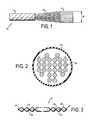
- FIG. 1is a top view of a cable of the present invention showing its various sections
- FIG. 2is an end view of a flat section of the cable wrapped in a round jacket
- FIG. 3is an end view of the flat section of the cable with the jacket removed.
- FIG. 1shows a multi-conductor cable 10 of the present invention, with various sections of the cable 10 exposed for clarity.
- the cable 10has a transparent outer jacket 12 that wraps the cable 10 into a generally uniform round shape.
- a portion of the outer jacket 12has been removed to show a first section with twisted pair conductors 14 , and a second section with flat parallel conductors 16 .
- the first 14 and second 16 sections of the cable 10are shown in FIG. 1 without the outer jacket 12 , this is done for illustrative purposes, and in use, the outer jacket 12 wraps the twisted pair conductors 14 into a generally uniform round shape.
- the uniform round shapeincreases the cable's flexibility allowing it to bend and be routed more easily, as well as achieve tightly controlled electrical performance.
- the cable 10is comprised mostly of the twisted pair conductors 14 of the first section, with the flat parallel conductors 16 of the second section spaced at uniform or non-uniform intervals along the cable's length. Both sections are wrapped by the outer jacket 12 , with the twisted pair section 14 being easily formed into the round shape, and the flat section 16 , which comprises a series of conductors 18 spaced evenly apart in parallel fashion, folded over to form the round-shaped cable, as shown in FIG. 2 .
- FIG. 2shows a folded arrangement referred to as a zigzag fold. However, other fold arrangements may be used without departing from the invention so long as they result in a generally uniform round-shaped cable.
- the twisted pair section 14reduces the crosstalk between the conductors 18 thereby enhancing the cable's electrical properties.
- the transparent outer jacket 12facilitates the preparation of the cable 10 for attachment to a connector (not shown) by allowing the flat section 16 to be easily located through the transparent jacket 12 .
- the jacket 12is may be made of a single or multi-layer clear Mylar, polyester plastic or other transparent material that has a heat activated adhesive that bonds the layers of the jacket to one another, but not to the conductors 18 lying underneath.
- a double layer of polyesteris used for mechanical protection as well as the need to keep the wrapped polyester from unraveling.
- a clear extruded jacketcould also be used, but it is difficult to strip these jackets without damaging the insulated conductors underneath.
- the conductors 18 in the flat section 16may be supported by a support member such as by being bonded between a first and second semi-rigid plastic laminate material 20 , 22 .
- the plastic laminates 20 , 22extend the entire width W of the cable 10 and are attached at their ends 24 and at points 26 in between the conductors 18 .
- the semi-rigid laminates 20 , 22provide an efficient and effective method of maintaining the spacing of the conductors 18 , by keeping them uniformly spaced apart so that the conductors 18 may be quickly attached to a connector having contact terminals with the same spacing as the conductors 18 . While FIG.
- laminates 20 , 22completely encasing conductor 18 , in other cables in which the spacing between conductors is smaller, laminates 20 , 22 will not attach between conductors.
- Other types of support membersmay be used, including one which supports the conductors from only one side.
- the flat section 16 of the cableis located through the transparent outer jacket 12 and the jacket is stripped off at that location.
- the jacket 12is then removed from around the flat section 16 to expose the conductors 18 . Because the outer jacket 12 is not bonded to the conductors 18 , the jacket 12 can be stripped off the conductors 18 without damaging the conductors 18 .
- FIG. 3shows the flat section 16 with the laminates 20 , 22 covering the conductors 18 .
- the exposed conductors 18are then attached to a connector by known means, such as by insulation displacement contacts.
Landscapes
- Insulated Conductors (AREA)
- Communication Cables (AREA)
Abstract
Description
The present invention is directed to an electrical cable having a helically wrapped transparent plastic jacket for wrapping a multi-conductor cable having a twisted pair conductor section and a flat parallel conductor section into a generally uniform round-shaped cable. The transparent jacket allows the flat parallel conductor section to be quickly identified for easier mass termination and attachment to a connector.
Mass termination connectors have become more commercially popular because of the time and cost savings compared to the traditional method of stripping and individually terminating each conductor using a crimp terminal. These connectors are often used with a flat ribbon-type cable in which several conductors run parallel to one another and are spaced to match the spacing of the terminal elements of the connector. The use of a flat cable allows the ends to be quickly attached to a connector without having to strip and position each of the conductors individually, as with traditional round cables. However, while flat cables offer advantages with respect to ease of termination, they are more difficult to route than round cables because they are less flexible, and consequently are more prone to damage. In addition, they cause significant airflow restriction problems within high performance electronic systems cabinets.
To overcome these disadvantages, cable manufacturers have taken standard flat cables with flat mass termination sections and manually folded them into a generally round-shaped cable, thus increasing the cable's flexibility and making it easier to route or lay the cable. In addition, cable manufacturers have usually manually covered this round-shaped cable with an additional covering such as nylon sleeving, or PVC tubing to protect the cable bundle. However, this method hinders the control of the cable's electrical properties because it is impossible with manual folding methods to predict how close the conductors are compressed together. A generally round-shaped cable has varying effective dielectric constants between the twisted pairs, due to the randomness of the manual folding and compression. This can cause wide variations in the cable's impedance and time delay, and consequently, increases the amount of reflection and crosstalk in the cable/connector system.
Another method of terminating a generally round cable is to take a standard round twisted pair cable having an extruded cover, remove the cover and then manually untwist each of the pairs on the end of the cable for termination. This process is costly due to the time and intensive labor involved. In addition, it is extremely costly to terminate the conductors when the connectors must be applied in the middle of the cable's length, as is the case with multi-drop SCSI cables.
Solutions to the above problems are suggested by U.S. Pat. No. 4,973,238 to Kihlken et al. which discloses a cable with a first twisted pair section and a second flat section wrapped in a non-transparent outer jacket into a generally round-shaped cable. A marker is placed on the outer jacket of the cable so that the location of the flat section of the cable can be identified for termination. However, it may be possible for the marker to be misplaced and incorrectly identify the location of the flat section.
Therefore it would be advantageous to provide a machine compacted uniformly round cable having a flat section for mass termination and attachment to a connector, and to provide a means for locating the flat section of the cable quickly and accurately. Such machine compaction would allow much more predictability of effective dielectric constant within the uniform round shape. It would also be advantageous to provide a means to easily strip the cable to expose the conductors therein for attachment to a connector, both at the ends and in the middle of the cable length.
The present invention is directed to a multi-conductor cable with a twisted pair section and a flat section, wrapped in a transparent plastic jacket to form a generally uniform round-shaped cable. The transparent jacket allows the flat section to be identified so that the jacket may be removed at this location and the flat section prepared for attachment to a connector for either point to point or daisy chain connection.
Additionally, the individual conductors in the flat section of the cable are each supported by a support member that maintains the spacing of the conductors. A connector having correspondingly spaced terminals can then be quickly attached to the conductors.
FIG. 1 is a top view of a cable of the present invention showing its various sections;
FIG. 2 is an end view of a flat section of the cable wrapped in a round jacket; and
FIG. 3 is an end view of the flat section of the cable with the jacket removed.
Referring now in detail to the drawings, FIG. 1 shows amulti-conductor cable 10 of the present invention, with various sections of thecable 10 exposed for clarity. Thecable 10 has a transparentouter jacket 12 that wraps thecable 10 into a generally uniform round shape. A portion of theouter jacket 12 has been removed to show a first section with twisted pair conductors14, and a second section with flat parallel conductors16. Although the first14 and second16 sections of thecable 10 are shown in FIG. 1 without theouter jacket 12, this is done for illustrative purposes, and in use, theouter jacket 12 wraps the twisted pair conductors14 into a generally uniform round shape. The uniform round shape increases the cable's flexibility allowing it to bend and be routed more easily, as well as achieve tightly controlled electrical performance.
Thecable 10 is comprised mostly of the twisted pair conductors14 of the first section, with the flat parallel conductors16 of the second section spaced at uniform or non-uniform intervals along the cable's length. Both sections are wrapped by theouter jacket 12, with the twisted pair section14 being easily formed into the round shape, and the flat section16, which comprises a series ofconductors 18 spaced evenly apart in parallel fashion, folded over to form the round-shaped cable, as shown in FIG.2. FIG. 2 shows a folded arrangement referred to as a zigzag fold. However, other fold arrangements may be used without departing from the invention so long as they result in a generally uniform round-shaped cable. In addition to being more easily formed into a round shape, the twisted pair section14 reduces the crosstalk between theconductors 18 thereby enhancing the cable's electrical properties.
The transparentouter jacket 12 facilitates the preparation of thecable 10 for attachment to a connector (not shown) by allowing the flat section16 to be easily located through thetransparent jacket 12. Thejacket 12 is may be made of a single or multi-layer clear Mylar, polyester plastic or other transparent material that has a heat activated adhesive that bonds the layers of the jacket to one another, but not to theconductors 18 lying underneath. A double layer of polyester is used for mechanical protection as well as the need to keep the wrapped polyester from unraveling. A clear extruded jacket could also be used, but it is difficult to strip these jackets without damaging the insulated conductors underneath. Although the preferred embodiment of thejacket 12 shown in FIG. 2 is a double-layered clear plastic, it should be understood that variations of the jacket are contemplated to be within the scope of the invention. For example, a single layer transparent jacket made from a variety of material may be used without departing from the intended purpose or spirit of the invention.
Theconductors 18 in the flat section16 may be supported by a support member such as by being bonded between a first and second semi-rigidplastic laminate material plastic laminates cable 10 and are attached at theirends 24 and atpoints 26 in between theconductors 18. Thesemi-rigid laminates conductors 18, by keeping them uniformly spaced apart so that theconductors 18 may be quickly attached to a connector having contact terminals with the same spacing as theconductors 18. While FIG. 3 showslaminates conductor 18, in other cables in which the spacing between conductors is smaller,laminates
To prepare thecable 10 for mass termination and attachment to a connector (not shown), the flat section16 of the cable is located through the transparentouter jacket 12 and the jacket is stripped off at that location. Thejacket 12 is then removed from around the flat section16 to expose theconductors 18. Because theouter jacket 12 is not bonded to theconductors 18, thejacket 12 can be stripped off theconductors 18 without damaging theconductors 18.
After thejacket 12 is removed, theconductors 18 comprising the flat section16 are laid out in the manner shown in FIG. 3 such that theconductors 18 lie parallel to one another. FIG. 3 shows the flat section16 with thelaminates conductors 18. The exposedconductors 18 are then attached to a connector by known means, such as by insulation displacement contacts.
Although preferred embodiments are specifically illustrated and described herein, it should be appreciated that many modifications and variations of the present invention are possible in light of the above teachings, without departing from the spirit or scope of the invention.
Claims (12)
1. A multi-conductor electrical cable comprising:
a cable having a first section with conductors arranged in twisted pairs and a second section with conductors positioned serially in a contiguous manner; and
a dual layer transparent jacket surrounding the cable in a generally uniform round configuration, the transparent jacket allowing the first section and second section to be seen through the transparent jacket, the two layers of the dual layer transparent jacket being bonded by a heat activated adhesive on their adjoining sides, and not adhesively bonded to the conductors so that the transparent jacket may be easily stripped from the conductors.
2. The multi-conductor electrical cable ofclaim 1 , wherein the conductors in the second section are encased by semi-rigid laminates which maintains the conductors in a uniformly spaced relationship.
3. The multi-conductor electrical cable ofclaim 2 , wherein the semi-rigid laminates comprises a first and second covering bonded to the conductors.
4. The multi-conductor electrical cable ofclaim 1 , wherein a plurality of first sections are located at spaced intervals between a plurality of second sections along the length of the cable.
5. An electrical cable comprising:
a plurality of conductors having one or more flat sections wherein the conductors in the flat sections are configured parallel to one another, the conductors being individually wrapped by semi-rigid laminates so as to uniformly space each conductor; and
a dual layer transparent jacket wrapped around the conductors so that the cable has a generally uniformly round shape, the two layers of the dual layer transparent jacket being bonded by a heat activated adhesive on their adjoining sides.
6. The electrical cable ofclaim 5 , further comprising one or more twisted pair sections wherein pairs of conductors in the twisted pair section are intertwined, and the flat sections and the twisted pair sections alternate along the length of the cable.
7. The electrical cable ofclaim 5 , wherein the semi-rigid laminates comprises first and second laminates bonded to each other.
8. The electrical cable ofclaim 5 , wherein the transparent jacket is not bonded to the conductors.
9. A method of attaching a cable to a connector comprising the steps of:
providing a multi-conductor cable with a plurality of conductors therein, the cable having a first flat section and a second section, wherein in the first section the conductors are arranged in a continguous series, and the cable is wrapped in a dual layer transparent jacket in a generally uniformly round configuration the two layers of the dual layer transparent jacket being bonded to one another by a heat activated adhesive on their adjoining sides;
locating the first section of the cable by looking through the transparent jacket;
stripping the transparent jacket of the cable to expose the conductors in the first section; and
attaching the conductors of the first section to a connector.
10. The method of attaching a cable to a connector ofclaim 9 , wherein the conductors in the first section are encased in semi-rigid laminates that maintains the spacing of the conductors.
11. The method of attaching a cable to a connector ofclaim 10 , wherein the transparent jacket is not bonded to the conductors so that when the transparent jacket is stripped it does not adhere to the conductors.
12. The method of attaching a cable to a connector ofclaim 9 , further comprising the step of:
placing the conductors in the first section in a generally flat configuration for attachment to connector having contacts that correspond with the conductors.
Priority Applications (4)
| Application Number | Priority Date | Filing Date | Title |
|---|---|---|---|
| US10/125,435US6717058B2 (en) | 2002-04-19 | 2002-04-19 | Multi-conductor cable with transparent jacket |
| TW092108877ATWI276119B (en) | 2002-04-19 | 2003-04-17 | Multi-conductor cable with transparent jacket |
| CN03142317ACN1453801A (en) | 2002-04-19 | 2003-04-18 | Multi-conductor cable with transparent sleeve |
| JP2003116260AJP2003331656A (en) | 2002-04-19 | 2003-04-21 | Multi-conductor cable with transparent jacket |
Applications Claiming Priority (1)
| Application Number | Priority Date | Filing Date | Title |
|---|---|---|---|
| US10/125,435US6717058B2 (en) | 2002-04-19 | 2002-04-19 | Multi-conductor cable with transparent jacket |
Publications (2)
| Publication Number | Publication Date |
|---|---|
| US20030196829A1 US20030196829A1 (en) | 2003-10-23 |
| US6717058B2true US6717058B2 (en) | 2004-04-06 |
Family
ID=29214791
Family Applications (1)
| Application Number | Title | Priority Date | Filing Date |
|---|---|---|---|
| US10/125,435Expired - Fee RelatedUS6717058B2 (en) | 2002-04-19 | 2002-04-19 | Multi-conductor cable with transparent jacket |
Country Status (4)
| Country | Link |
|---|---|
| US (1) | US6717058B2 (en) |
| JP (1) | JP2003331656A (en) |
| CN (1) | CN1453801A (en) |
| TW (1) | TWI276119B (en) |
Cited By (26)
| Publication number | Priority date | Publication date | Assignee | Title |
|---|---|---|---|---|
| US20040262027A1 (en)* | 2001-06-14 | 2004-12-30 | Andrew Kaczmarski | Communications cable provided with a crosstalk barrier for use at high transmission frequencies |
| US20050040158A1 (en)* | 2002-08-08 | 2005-02-24 | Jean-Pierre Bamy Bamy | Heating conductor comprising a sheath |
| US6958444B1 (en)* | 2005-02-03 | 2005-10-25 | Hon Hai Precision Ind. Co., Ltd. | Round-flat twisted pair cable assembly |
| US20070209824A1 (en)* | 2006-03-09 | 2007-09-13 | Spring Stutzman | Multi-pair cable with channeled jackets |
| US20120090866A1 (en)* | 2009-06-19 | 2012-04-19 | Gundel Douglas B | Shielded electrical cable and method of making |
| US20130016952A1 (en)* | 2011-05-26 | 2013-01-17 | Thomas Knuth | Fiber optic distribution device |
| US8466365B2 (en)* | 2010-08-31 | 2013-06-18 | 3M Innovative Properties Company | Shielded electrical cable |
| US8492655B2 (en) | 2010-08-31 | 2013-07-23 | 3M Innovative Properties Company | Shielded electrical ribbon cable with dielectric spacing |
| US8575491B2 (en) | 2010-08-31 | 2013-11-05 | 3M Innovative Properties Company | Electrical cable with shielding film with gradual reduced transition area |
| US8841554B2 (en) | 2010-08-31 | 2014-09-23 | 3M Innovative Properties Company | High density shielded electrical cable and other shielded cables, systems, and methods |
| US8859901B2 (en) | 2010-09-23 | 2014-10-14 | 3M Innovative Properties Company | Shielded electrical cable |
| US9064618B2 (en) | 2010-05-27 | 2015-06-23 | Prysmian Power Cables And Systems Usa, Llc | Electrical cable with semi-conductive outer layer distinguishable from jacket |
| US9119292B2 (en) | 2010-08-31 | 2015-08-25 | 3M Innovative Properties Company | Shielded electrical cable in twinaxial configuration |
| US9219546B2 (en) | 2011-12-12 | 2015-12-22 | Corning Optical Communications LLC | Extremely high frequency (EHF) distributed antenna systems, and related components and methods |
| US9323020B2 (en) | 2008-10-09 | 2016-04-26 | Corning Cable Systems (Shanghai) Co. Ltd | Fiber optic terminal having adapter panel supporting both input and output fibers from an optical splitter |
| US9336930B2 (en) | 2010-06-11 | 2016-05-10 | Olympus Corporation | Composite cable and method of manufacturing composite cable |
| US9547145B2 (en) | 2010-10-19 | 2017-01-17 | Corning Optical Communications LLC | Local convergence point for multiple dwelling unit fiber optic distribution network |
| US9685259B2 (en) | 2009-06-19 | 2017-06-20 | 3M Innovative Properties Company | Shielded electrical cable |
| WO2017151779A1 (en) | 2016-03-02 | 2017-09-08 | Heartware, Inc. | Skin button with flat cable |
| US9799426B2 (en) | 2012-11-08 | 2017-10-24 | 3M Innovative Properties Company | Ribbed high density electrical cable |
| US20180268959A1 (en)* | 2015-01-15 | 2018-09-20 | Autonetworks Technologies, Ltd. | Electrical cable, terminal-equipped electrical cable, and method of manufacturing terminal-equipped electrical cable |
| US10110307B2 (en) | 2012-03-02 | 2018-10-23 | Corning Optical Communications LLC | Optical network units (ONUs) for high bandwidth connectivity, and related components and methods |
| US10147522B2 (en) | 2010-08-31 | 2018-12-04 | 3M Innovative Properties Company | Electrical characteristics of shielded electrical cables |
| US20190097351A1 (en)* | 2017-09-23 | 2019-03-28 | Luxshare Precision Industry Co., Ltd. | Round cable |
| US10510467B2 (en) | 2012-12-06 | 2019-12-17 | 3M Innovative Properties Company | Shielded cable |
| US20230290542A1 (en)* | 2010-08-31 | 2023-09-14 | 3M Innovative Properties Company | Shielded electric cable |
Families Citing this family (5)
| Publication number | Priority date | Publication date | Assignee | Title |
|---|---|---|---|---|
| DE102006039604A1 (en)* | 2006-08-24 | 2008-02-28 | Weidmüller Interface GmbH & Co. KG | Cable, connector with cable and method of making the cable |
| JP2009179117A (en)* | 2008-01-29 | 2009-08-13 | Autonetworks Technologies Ltd | Automotive wire harness |
| CN104217808A (en)* | 2014-08-29 | 2014-12-17 | 安徽华菱电缆集团有限公司 | Movable power cable |
| US10160324B2 (en)* | 2014-12-31 | 2018-12-25 | Chargepoint, Inc. | Automatically sensing a type of charging cable and setting maximum amperage output of an electric vehicle charging station accordingly |
| US10460853B2 (en) | 2016-05-24 | 2019-10-29 | Flex-Cable | Power cable and bus bar with transitional cross sections |
Citations (34)
| Publication number | Priority date | Publication date | Assignee | Title |
|---|---|---|---|---|
| US3778879A (en) | 1971-08-13 | 1973-12-18 | Walpro Plastics Nv | Method and device for manufacturing a flat cable as well as a cable acquired by means of the same |
| GB1432548A (en)* | 1972-08-02 | 1976-04-22 | Bicc Ltd | Electric cables |
| US4034148A (en)* | 1975-01-30 | 1977-07-05 | Spectra-Strip Corporation | Twisted pair multi-conductor ribbon cable with intermittent straight sections |
| US4096006A (en) | 1976-09-22 | 1978-06-20 | Spectra-Strip Corporation | Method and apparatus for making twisted pair multi-conductor ribbon cable with intermittent straight sections |
| US4218581A (en)* | 1977-12-29 | 1980-08-19 | Hirosuke Suzuki | High frequency flat cable |
| US4277642A (en)* | 1978-09-15 | 1981-07-07 | Western Electric Company, Inc. | Cordage having a plurality of conductors in a partitioned jacket |
| US4359597A (en) | 1976-09-22 | 1982-11-16 | Eltra Corporation | Twisted pair multi-conductor ribbon cable with intermittent straight sections |
| US4413469A (en)* | 1981-03-23 | 1983-11-08 | Allied Corporation | Method of making low crosstalk ribbon cable |
| US4439631A (en) | 1981-09-14 | 1984-03-27 | Charles Shields | Method and machine for preparing an end portion of a multi-conductor flat cable for receiving a connector thereon |
| DE3333996A1 (en)* | 1982-09-24 | 1984-04-05 | Kabelwerk Wagner Kg, 5600 Wuppertal | Section of a movable electrical lead |
| DE3405302A1 (en)* | 1984-02-15 | 1985-09-05 | Wolfgang Dipl.-Ing. 2351 Trappenkamp Freitag | Electrical loudspeaker cable |
| US4564723A (en)* | 1983-11-21 | 1986-01-14 | Allied Corporation | Shielded ribbon cable and method |
| US4606595A (en) | 1984-04-25 | 1986-08-19 | Amp Incorporated | Premise wiring system and components therefor |
| DE3513620A1 (en)* | 1985-04-16 | 1986-10-16 | Kabelwerke Reinshagen Gmbh, 5600 Wuppertal | Electrical cable with a pattern |
| US4767891A (en)* | 1985-11-18 | 1988-08-30 | Cooper Industries, Inc. | Mass terminable flat cable and cable assembly incorporating the cable |
| US4924037A (en)* | 1988-12-20 | 1990-05-08 | W. L. Gore & Associates, Inc. | Electrical cable |
| US4928379A (en) | 1986-04-24 | 1990-05-29 | Amphenol Corporation | Press for use in aligning and terminating flat cable |
| US4967040A (en)* | 1988-12-13 | 1990-10-30 | Societe Anonyme Dite: Filotex | Screened electric cable provided with zones for rapid parallel connection |
| US4973238A (en) | 1989-12-05 | 1990-11-27 | Cooper Industries, Inc. | Apparatus for manufacturing an electrical cable |
| US4978813A (en)* | 1989-08-29 | 1990-12-18 | W. L. Gore & Associates, Inc. | Electrical cable |
| JPH0357109A (en)* | 1989-07-26 | 1991-03-12 | Hitachi Cable Ltd | Manufacture of twisted flat cable |
| US5142105A (en) | 1989-12-05 | 1992-08-25 | Cooper Industries, Inc. | Electrical cable and method for manufacturing the same |
| US5387298A (en) | 1992-04-23 | 1995-02-07 | Fujikura Ltd. | Apparatus and method for bonding sheet material and its application to manufacture of flexible flat cable |
| US5900588A (en)* | 1997-07-25 | 1999-05-04 | Minnesota Mining And Manufacturing Company | Reduced skew shielded ribbon cable |
| US5973268A (en)* | 1997-12-09 | 1999-10-26 | Cheng; Yu-Feng | Multicolor electric cable |
| JP2000299017A (en)* | 1999-04-14 | 2000-10-24 | Hitachi Cable Ltd | Flat cable |
| JP2001184953A (en)* | 1999-12-22 | 2001-07-06 | Hitachi Cable Ltd | Twist flat cable |
| US6270598B1 (en) | 1999-05-13 | 2001-08-07 | Hitachi Cable, Ltd. | Process and apparatus for producing flat cable |
| JP2002025354A (en)* | 2000-07-11 | 2002-01-25 | Hitachi Cable Ltd | Twist flat cable |
| US6348651B1 (en)* | 2000-03-27 | 2002-02-19 | Hon Hai Precision Ind. Co., Ltd. | Twist pattern to improve electrical performances of twisted-pair cable |
| US6388194B1 (en)* | 1994-09-27 | 2002-05-14 | Hazardguard, Inc. | Electrical cable having indicating malfunction means therein |
| US6392155B1 (en)* | 1999-05-07 | 2002-05-21 | Hitachi Cable, Ltd. | Flat cable and process for producing the same |
| US20020088639A1 (en)* | 2000-05-19 | 2002-07-11 | Cheng-Lang Tsai | Color cable and the manufacturing method therefor |
| US6476329B2 (en)* | 1999-04-08 | 2002-11-05 | Hitachi Cable, Ltd. | Twisted flat cable |
- 2002
- 2002-04-19USUS10/125,435patent/US6717058B2/ennot_activeExpired - Fee Related
- 2003
- 2003-04-17TWTW092108877Apatent/TWI276119B/ennot_activeIP Right Cessation
- 2003-04-18CNCN03142317Apatent/CN1453801A/enactivePending
- 2003-04-21JPJP2003116260Apatent/JP2003331656A/enactivePending
Patent Citations (35)
| Publication number | Priority date | Publication date | Assignee | Title |
|---|---|---|---|---|
| US3778879A (en) | 1971-08-13 | 1973-12-18 | Walpro Plastics Nv | Method and device for manufacturing a flat cable as well as a cable acquired by means of the same |
| GB1432548A (en)* | 1972-08-02 | 1976-04-22 | Bicc Ltd | Electric cables |
| US4034148A (en)* | 1975-01-30 | 1977-07-05 | Spectra-Strip Corporation | Twisted pair multi-conductor ribbon cable with intermittent straight sections |
| US4096006A (en) | 1976-09-22 | 1978-06-20 | Spectra-Strip Corporation | Method and apparatus for making twisted pair multi-conductor ribbon cable with intermittent straight sections |
| US4202722A (en) | 1976-09-22 | 1980-05-13 | Spectra-Strip | Apparatus for making twisted pair multi-conductor ribbon cable with intermittent straight sections |
| US4359597A (en) | 1976-09-22 | 1982-11-16 | Eltra Corporation | Twisted pair multi-conductor ribbon cable with intermittent straight sections |
| US4218581A (en)* | 1977-12-29 | 1980-08-19 | Hirosuke Suzuki | High frequency flat cable |
| US4277642A (en)* | 1978-09-15 | 1981-07-07 | Western Electric Company, Inc. | Cordage having a plurality of conductors in a partitioned jacket |
| US4413469A (en)* | 1981-03-23 | 1983-11-08 | Allied Corporation | Method of making low crosstalk ribbon cable |
| US4439631A (en) | 1981-09-14 | 1984-03-27 | Charles Shields | Method and machine for preparing an end portion of a multi-conductor flat cable for receiving a connector thereon |
| DE3333996A1 (en)* | 1982-09-24 | 1984-04-05 | Kabelwerk Wagner Kg, 5600 Wuppertal | Section of a movable electrical lead |
| US4564723A (en)* | 1983-11-21 | 1986-01-14 | Allied Corporation | Shielded ribbon cable and method |
| DE3405302A1 (en)* | 1984-02-15 | 1985-09-05 | Wolfgang Dipl.-Ing. 2351 Trappenkamp Freitag | Electrical loudspeaker cable |
| US4606595A (en) | 1984-04-25 | 1986-08-19 | Amp Incorporated | Premise wiring system and components therefor |
| DE3513620A1 (en)* | 1985-04-16 | 1986-10-16 | Kabelwerke Reinshagen Gmbh, 5600 Wuppertal | Electrical cable with a pattern |
| US4767891A (en)* | 1985-11-18 | 1988-08-30 | Cooper Industries, Inc. | Mass terminable flat cable and cable assembly incorporating the cable |
| US4928379A (en) | 1986-04-24 | 1990-05-29 | Amphenol Corporation | Press for use in aligning and terminating flat cable |
| US4967040A (en)* | 1988-12-13 | 1990-10-30 | Societe Anonyme Dite: Filotex | Screened electric cable provided with zones for rapid parallel connection |
| US4924037A (en)* | 1988-12-20 | 1990-05-08 | W. L. Gore & Associates, Inc. | Electrical cable |
| JPH0357109A (en)* | 1989-07-26 | 1991-03-12 | Hitachi Cable Ltd | Manufacture of twisted flat cable |
| US4978813A (en)* | 1989-08-29 | 1990-12-18 | W. L. Gore & Associates, Inc. | Electrical cable |
| US4973238A (en) | 1989-12-05 | 1990-11-27 | Cooper Industries, Inc. | Apparatus for manufacturing an electrical cable |
| US5142105A (en) | 1989-12-05 | 1992-08-25 | Cooper Industries, Inc. | Electrical cable and method for manufacturing the same |
| US5387298A (en) | 1992-04-23 | 1995-02-07 | Fujikura Ltd. | Apparatus and method for bonding sheet material and its application to manufacture of flexible flat cable |
| US6388194B1 (en)* | 1994-09-27 | 2002-05-14 | Hazardguard, Inc. | Electrical cable having indicating malfunction means therein |
| US5900588A (en)* | 1997-07-25 | 1999-05-04 | Minnesota Mining And Manufacturing Company | Reduced skew shielded ribbon cable |
| US5973268A (en)* | 1997-12-09 | 1999-10-26 | Cheng; Yu-Feng | Multicolor electric cable |
| US6476329B2 (en)* | 1999-04-08 | 2002-11-05 | Hitachi Cable, Ltd. | Twisted flat cable |
| JP2000299017A (en)* | 1999-04-14 | 2000-10-24 | Hitachi Cable Ltd | Flat cable |
| US6392155B1 (en)* | 1999-05-07 | 2002-05-21 | Hitachi Cable, Ltd. | Flat cable and process for producing the same |
| US6270598B1 (en) | 1999-05-13 | 2001-08-07 | Hitachi Cable, Ltd. | Process and apparatus for producing flat cable |
| JP2001184953A (en)* | 1999-12-22 | 2001-07-06 | Hitachi Cable Ltd | Twist flat cable |
| US6348651B1 (en)* | 2000-03-27 | 2002-02-19 | Hon Hai Precision Ind. Co., Ltd. | Twist pattern to improve electrical performances of twisted-pair cable |
| US20020088639A1 (en)* | 2000-05-19 | 2002-07-11 | Cheng-Lang Tsai | Color cable and the manufacturing method therefor |
| JP2002025354A (en)* | 2000-07-11 | 2002-01-25 | Hitachi Cable Ltd | Twist flat cable |
Cited By (117)
| Publication number | Priority date | Publication date | Assignee | Title |
|---|---|---|---|---|
| US20040262027A1 (en)* | 2001-06-14 | 2004-12-30 | Andrew Kaczmarski | Communications cable provided with a crosstalk barrier for use at high transmission frequencies |
| US7923638B2 (en)* | 2001-06-14 | 2011-04-12 | Prysmian Telecom Cables & Systems Australia Pty Ltd | Communications cable provided with a crosstalk barrier for use at high transmission frequencies |
| US20050040158A1 (en)* | 2002-08-08 | 2005-02-24 | Jean-Pierre Bamy Bamy | Heating conductor comprising a sheath |
| US6958444B1 (en)* | 2005-02-03 | 2005-10-25 | Hon Hai Precision Ind. Co., Ltd. | Round-flat twisted pair cable assembly |
| US20070209824A1 (en)* | 2006-03-09 | 2007-09-13 | Spring Stutzman | Multi-pair cable with channeled jackets |
| US7271344B1 (en) | 2006-03-09 | 2007-09-18 | Adc Telecommunications, Inc. | Multi-pair cable with channeled jackets |
| US20080115959A1 (en)* | 2006-03-09 | 2008-05-22 | Adc Telecommunications, Inc. | Multi-pair cable with channeled jackets |
| US7629536B2 (en) | 2006-03-09 | 2009-12-08 | Adc Telecommunications, Inc. | Multi-pair cable with channeled jackets |
| US9323020B2 (en) | 2008-10-09 | 2016-04-26 | Corning Cable Systems (Shanghai) Co. Ltd | Fiber optic terminal having adapter panel supporting both input and output fibers from an optical splitter |
| US10080319B2 (en) | 2009-06-19 | 2018-09-18 | 3M Innovative Properties Company | Shielded electrical cable |
| US9715951B2 (en) | 2009-06-19 | 2017-07-25 | 3M Innovative Properties Company | Shielded electrical cable |
| US10306819B2 (en) | 2009-06-19 | 2019-05-28 | 3M Innovative Properties Company | Shielded electrical cable |
| US9324477B2 (en)* | 2009-06-19 | 2016-04-26 | 3M Innovative Properties Company | Shielded electrical cable |
| US9883620B2 (en) | 2009-06-19 | 2018-01-30 | 3M Innovative Properties Company | Shielded electrical cable |
| US9763369B2 (en) | 2009-06-19 | 2017-09-12 | 3M Innovative Properties Company | Shielded electrical cable |
| US20120090872A1 (en)* | 2009-06-19 | 2012-04-19 | Gundel Douglas B | Shielded electrical cable |
| US8658899B2 (en)* | 2009-06-19 | 2014-02-25 | 3M Innovative Properties Company | Shielded electrical cable |
| US20140116748A1 (en)* | 2009-06-19 | 2014-05-01 | 3M Innovative Properties Company | Shielded Electrical Cable |
| US10448547B2 (en) | 2009-06-19 | 2019-10-15 | 3M Innovative Properties Company | Shielded electrical cable |
| US9685259B2 (en) | 2009-06-19 | 2017-06-20 | 3M Innovative Properties Company | Shielded electrical cable |
| US9686893B2 (en) | 2009-06-19 | 2017-06-20 | 3M Innovative Properties Company | Shielded electrical cable |
| US9035186B2 (en)* | 2009-06-19 | 2015-05-19 | 3M Innovative Properties Company | Shielded electrical cable |
| US8946558B2 (en) | 2009-06-19 | 2015-02-03 | 3M Innovative Properties Company | Shielded electrical cable |
| US20120090866A1 (en)* | 2009-06-19 | 2012-04-19 | Gundel Douglas B | Shielded electrical cable and method of making |
| US9064618B2 (en) | 2010-05-27 | 2015-06-23 | Prysmian Power Cables And Systems Usa, Llc | Electrical cable with semi-conductive outer layer distinguishable from jacket |
| US9336930B2 (en) | 2010-06-11 | 2016-05-10 | Olympus Corporation | Composite cable and method of manufacturing composite cable |
| US9715952B2 (en) | 2010-08-31 | 2017-07-25 | 3M Innovative Properties Company | Electrical characteristics of shielded electrical cables |
| US10109396B2 (en) | 2010-08-31 | 2018-10-23 | 3M Innovative Properties Company | Electrical characteristics of shielded electrical cables |
| US9119292B2 (en) | 2010-08-31 | 2015-08-25 | 3M Innovative Properties Company | Shielded electrical cable in twinaxial configuration |
| US12205733B2 (en)* | 2010-08-31 | 2025-01-21 | 3M Innovative Properties Company | Shielded electrical cable |
| US9196397B2 (en)* | 2010-08-31 | 2015-11-24 | 3M Innovative Properties Company | Shielded electrical cable |
| US9202609B2 (en) | 2010-08-31 | 2015-12-01 | 3M Innovative Properties Company | Connector arrangements for shielded electrical cables |
| US9202608B2 (en) | 2010-08-31 | 2015-12-01 | 3M Innovative Properties Company | Connector arrangements for shielded electrical cables |
| US9208927B2 (en)* | 2010-08-31 | 2015-12-08 | 3M Innovative Properties Company | Shielded electrical cable |
| US12205732B2 (en)* | 2010-08-31 | 2025-01-21 | 3M Innovative Properties Company | Shielded electric cable |
| US20160049220A1 (en)* | 2010-08-31 | 2016-02-18 | 3M Innovative Properties Company | Shielded electrical cable |
| US9064612B2 (en) | 2010-08-31 | 2015-06-23 | 3M Innovative Properties Company | Shielded electrical ribbon cable with dielectric spacing |
| US20150083460A1 (en)* | 2010-08-31 | 2015-03-26 | 3M Innovative Properties Company | Shielded Electrical Cable |
| US9325121B2 (en) | 2010-08-31 | 2016-04-26 | 3M Innovative Properties Company | Connector arrangements for shielded electrical cables |
| US8933333B2 (en)* | 2010-08-31 | 2015-01-13 | 3M Innovative Properties Company | Shielded electrical cable |
| US9443644B2 (en) | 2010-08-31 | 2016-09-13 | 3M Innovative Properties Company | High density shielded electrical cable and other shielded cables, systems, and methods |
| US9449738B2 (en) | 2010-08-31 | 2016-09-20 | 3M Innovative Properties Company | High density shielded electrical cable and other shielded cables, systems, and methods |
| US9502154B1 (en) | 2010-08-31 | 2016-11-22 | 3M Innovative Properties Company | High density shielded electrical cable and other shielded cables, systems, and methods |
| US20240212879A1 (en)* | 2010-08-31 | 2024-06-27 | 3M Innovative Properties Company | High density shielded electrical cable and other shielded cables, systems, and methods |
| US9595371B2 (en) | 2010-08-31 | 2017-03-14 | 3M Innovative Properties Company | High density shielded electrical cable and other shielded cables, systems, and methods |
| US20240087773A1 (en)* | 2010-08-31 | 2024-03-14 | 3M Innovative Properties Company | Shielded electrical cable |
| US9601236B2 (en)* | 2010-08-31 | 2017-03-21 | 3M Innovative Properties Company | Shielded electrical cable |
| US9607735B2 (en) | 2010-08-31 | 2017-03-28 | 3M Innovative Properties Company | Shielded electrical ribbon cable with dielectric spacing |
| US9607734B2 (en) | 2010-08-31 | 2017-03-28 | 3M Innovative Properties Company | Shielded electrical ribbon cable with dielectric spacing |
| US9627106B2 (en) | 2010-08-31 | 2017-04-18 | 3M Innovative Properties Company | High density shielded electrical cable and other shielded cables, systems, and methods |
| US9646740B2 (en) | 2010-08-31 | 2017-05-09 | 3M Innovative Properties Company | Electrical characteristics of shielded electrical cables |
| US9653195B2 (en)* | 2010-08-31 | 2017-05-16 | 3M Innovative Properties Company | Shielded electrical cable |
| US20170148549A1 (en)* | 2010-08-31 | 2017-05-25 | 3M Innovative Properties Company | Shielded electrical cable |
| US9666332B1 (en) | 2010-08-31 | 2017-05-30 | 3M Innovative Properties Company | High density shielded electrical cable and other shielded cables, systems, and methods |
| US11923112B2 (en) | 2010-08-31 | 2024-03-05 | 3M Innovative Properties Company | High density shielded electrical cable and other shielded cables, systems, and methods |
| US8841554B2 (en) | 2010-08-31 | 2014-09-23 | 3M Innovative Properties Company | High density shielded electrical cable and other shielded cables, systems, and methods |
| US9704619B1 (en) | 2010-08-31 | 2017-07-11 | 3M Innovative Properties Company | Electrical characteristics of shielded electrical cables |
| US8841555B2 (en) | 2010-08-31 | 2014-09-23 | 3M Innovative Properties Company | Connector arrangements for shielded electrical cables |
| US20140000930A1 (en)* | 2010-08-31 | 2014-01-02 | 3M Innovative Properties Company | Shielded Electrical Cable |
| US11854716B2 (en)* | 2010-08-31 | 2023-12-26 | 3M Innovative Properties Company | Shielded electrical cable |
| US20230290542A1 (en)* | 2010-08-31 | 2023-09-14 | 3M Innovative Properties Company | Shielded electric cable |
| US8575491B2 (en) | 2010-08-31 | 2013-11-05 | 3M Innovative Properties Company | Electrical cable with shielding film with gradual reduced transition area |
| US9786411B2 (en) | 2010-08-31 | 2017-10-10 | 3M Innovative Properties Company | Electrical characteristics of shielded electrical cables |
| US20230253132A1 (en)* | 2010-08-31 | 2023-08-10 | 3M Innovative Properties Company | High density shielded electrical cable and other shielded cables, systems, and methods |
| US11699536B2 (en) | 2010-08-31 | 2023-07-11 | 3M Innovative Properties Company | High density shielded electrical cable and other shielded cables, systems, and methods |
| US9865378B2 (en)* | 2010-08-31 | 2018-01-09 | 3M Innovative Properties Company | Shielded electrical cable |
| US20130264089A1 (en)* | 2010-08-31 | 2013-10-10 | 3M Innovative Properties Company | Shielded Electrical Cable |
| US9892823B2 (en) | 2010-08-31 | 2018-02-13 | 3M Innovative Properties Company | High density shielded electrical cable and other shielded cables, systems, and methods |
| US10056170B2 (en) | 2010-08-31 | 2018-08-21 | 3M Innovative Properties Company | High density shielded electrical cable and other shielded cables, systems, and methods |
| US8492655B2 (en) | 2010-08-31 | 2013-07-23 | 3M Innovative Properties Company | Shielded electrical ribbon cable with dielectric spacing |
| US11688530B2 (en)* | 2010-08-31 | 2023-06-27 | 3M Innovative Properties Company | Shielded electric cable |
| US10090082B2 (en)* | 2010-08-31 | 2018-10-02 | 3M Innovative Properties Company | Shielded electrical cable |
| US9105376B2 (en) | 2010-08-31 | 2015-08-11 | 3M Innovative Properties Company | Connector arrangements for shielded electrical cables |
| US11664137B2 (en) | 2010-08-31 | 2023-05-30 | 3M Innovative Properties Company | High density shielded electrical cable and other shielded cables, systems, and methods |
| US11651871B2 (en)* | 2010-08-31 | 2023-05-16 | 3M Innovative Properties Company | Shielded electric cable |
| US10109397B2 (en) | 2010-08-31 | 2018-10-23 | 3M Innovative Properties Company | Electrical characteristics of shielded electrical cables |
| US10134506B2 (en) | 2010-08-31 | 2018-11-20 | 3M Innovative Properties Company | Electrical characteristics of shielded electrical cables |
| US10147522B2 (en) | 2010-08-31 | 2018-12-04 | 3M Innovative Properties Company | Electrical characteristics of shielded electrical cables |
| US20180374610A1 (en)* | 2010-08-31 | 2018-12-27 | 3M Innovative Properties Company | Shielded electrical cable |
| US20220367087A1 (en)* | 2010-08-31 | 2022-11-17 | 3M Innovative Properties Company | Shielded electrical cable |
| US11488745B2 (en)* | 2010-08-31 | 2022-11-01 | 3M Innovative Properties Company | Shielded electrical cable |
| US20220270786A1 (en)* | 2010-08-31 | 2022-08-25 | 3M Innovative Properties Company | Shielded electric cable |
| US8466365B2 (en)* | 2010-08-31 | 2013-06-18 | 3M Innovative Properties Company | Shielded electrical cable |
| US10340059B2 (en)* | 2010-08-31 | 2019-07-02 | 3M Innovative Properties Company | Shielded electrical cable |
| US10347393B2 (en) | 2010-08-31 | 2019-07-09 | 3M Innovative Properties Company | High density shielded electrical cable and other shielded cables, systems, and methods |
| US10347398B2 (en) | 2010-08-31 | 2019-07-09 | 3M Innovative Properties Company | Electrical characteristics of shielded electrical cables |
| US10373734B2 (en) | 2010-08-31 | 2019-08-06 | 3M Innovative Properties Company | Shielded electrical ribbon cable with dielectric spacing |
| US20220230783A1 (en)* | 2010-08-31 | 2022-07-21 | 3M Innovative Properties Company | Shielded electric cable |
| US11348706B2 (en)* | 2010-08-31 | 2022-05-31 | 3M Innovative Properties Company | Shielded electrical cable |
| US10438725B2 (en) | 2010-08-31 | 2019-10-08 | 3M Innovative Properties Company | Electrical characteristics of shielded electrical cables |
| US10998111B2 (en)* | 2010-08-31 | 2021-05-04 | 3M Innovative Properties Company | Shielded electrical cable |
| US10896772B2 (en) | 2010-08-31 | 2021-01-19 | 3M Innovative Properties Company | High density shielded electrical cable and other shielded cables, systems, and methods |
| US10784021B2 (en)* | 2010-08-31 | 2020-09-22 | 3M Innovative Properties Company | Shielded electrical cable |
| US10573432B2 (en)* | 2010-08-31 | 2020-02-25 | 3M Innovative Properties Company | Shielded electrical cable |
| US10573427B2 (en) | 2010-08-31 | 2020-02-25 | 3M Innovative Properties Company | Shielded electrical ribbon cable with dielectric spacing |
| US10629329B2 (en) | 2010-08-31 | 2020-04-21 | 3M Innovative Properties Company | High density shielded electrical cable and other shielded cables, systems, and methods |
| US20200161023A1 (en)* | 2010-08-31 | 2020-05-21 | 3M Innovative Properties Company | Shielded electrical cable |
| US9129724B2 (en) | 2010-09-23 | 2015-09-08 | 3M Innovative Properties Company | Shielded electrical cable |
| US8859901B2 (en) | 2010-09-23 | 2014-10-14 | 3M Innovative Properties Company | Shielded electrical cable |
| US9547145B2 (en) | 2010-10-19 | 2017-01-17 | Corning Optical Communications LLC | Local convergence point for multiple dwelling unit fiber optic distribution network |
| US9720197B2 (en) | 2010-10-19 | 2017-08-01 | Corning Optical Communications LLC | Transition box for multiple dwelling unit fiber optic distribution network |
| US20130016952A1 (en)* | 2011-05-26 | 2013-01-17 | Thomas Knuth | Fiber optic distribution device |
| US9219546B2 (en) | 2011-12-12 | 2015-12-22 | Corning Optical Communications LLC | Extremely high frequency (EHF) distributed antenna systems, and related components and methods |
| US9602209B2 (en) | 2011-12-12 | 2017-03-21 | Corning Optical Communications LLC | Extremely high frequency (EHF) distributed antenna systems, and related components and methods |
| US10110305B2 (en) | 2011-12-12 | 2018-10-23 | Corning Optical Communications LLC | Extremely high frequency (EHF) distributed antenna systems, and related components and methods |
| US9800339B2 (en) | 2011-12-12 | 2017-10-24 | Corning Optical Communications LLC | Extremely high frequency (EHF) distributed antenna systems, and related components and methods |
| US10110307B2 (en) | 2012-03-02 | 2018-10-23 | Corning Optical Communications LLC | Optical network units (ONUs) for high bandwidth connectivity, and related components and methods |
| US10418152B2 (en) | 2012-11-08 | 2019-09-17 | 3M Innovative Properties Company | Ribbed high density electrical cable |
| US9799426B2 (en) | 2012-11-08 | 2017-10-24 | 3M Innovative Properties Company | Ribbed high density electrical cable |
| US10510467B2 (en) | 2012-12-06 | 2019-12-17 | 3M Innovative Properties Company | Shielded cable |
| US10249408B2 (en)* | 2015-01-15 | 2019-04-02 | Autonetworks Technologies, Ltd. | Electrical cable, terminal-equipped electrical cable, and method of manufacturing terminal-equipped electrical cable |
| US20180268959A1 (en)* | 2015-01-15 | 2018-09-20 | Autonetworks Technologies, Ltd. | Electrical cable, terminal-equipped electrical cable, and method of manufacturing terminal-equipped electrical cable |
| WO2017151779A1 (en) | 2016-03-02 | 2017-09-08 | Heartware, Inc. | Skin button with flat cable |
| US10186352B2 (en) | 2016-03-02 | 2019-01-22 | Medtronic HeartWare, Inc. | Skin button with flat cable |
| US10460857B2 (en) | 2016-03-02 | 2019-10-29 | Heartware, Inc. | Skin button with flat cable |
| US20190097351A1 (en)* | 2017-09-23 | 2019-03-28 | Luxshare Precision Industry Co., Ltd. | Round cable |
| US10424868B2 (en)* | 2017-09-23 | 2019-09-24 | Luxshare Precision Industry Co., Ltd. | Round cable |
Also Published As
| Publication number | Publication date |
|---|---|
| JP2003331656A (en) | 2003-11-21 |
| TWI276119B (en) | 2007-03-11 |
| TW200403695A (en) | 2004-03-01 |
| US20030196829A1 (en) | 2003-10-23 |
| CN1453801A (en) | 2003-11-05 |
Similar Documents
| Publication | Publication Date | Title |
|---|---|---|
| US6717058B2 (en) | Multi-conductor cable with transparent jacket | |
| US5084594A (en) | Multiwire cable | |
| WO2006127723A2 (en) | Flat cable shield ground connection | |
| US4800236A (en) | Cable having a corrugated septum | |
| US6580034B2 (en) | Flexible interconnect cable with ribbonized ends | |
| JPH06267339A (en) | Flat ribbon cable and hybrid cable using said cable | |
| CN101507051A (en) | Grounding structure and grounding method for shield wire | |
| CN101286378B (en) | cable harness | |
| US8704088B2 (en) | Electrical connecting cable | |
| JPH06506796A (en) | electric cable | |
| CN102414763A (en) | Multi-core coaxial cable with connecting member and method of manufacturing same | |
| EP0136040A2 (en) | Round jacketed electrical cable | |
| US4943688A (en) | Ribbon coaxial cable with offset drain wires | |
| US20030000728A1 (en) | Flexible interconnect cable with ribbonized ends and method of manufacturing | |
| CN1293574C (en) | Flexible interconnect cable with ribbonized ends and method of manufacturing | |
| US5030137A (en) | Flat cable jumper | |
| US20020062980A1 (en) | Cable system | |
| KR20030013325A (en) | Insulating cover | |
| JPH0229609Y2 (en) | ||
| JP3039281B2 (en) | Wire harness with shield | |
| JP2002093246A (en) | Flat cable, method of manufacturing the same, and insulating sheet used for them | |
| US4769515A (en) | Primary transmission line cable | |
| JPS5998409A (en) | flat cable | |
| JPS5894704A (en) | Harness | |
| JPH04155779A (en) | Connection parts and connection method of insulated wires |
Legal Events
| Date | Code | Title | Description |
|---|---|---|---|
| CC | Certificate of correction | ||
| REMI | Maintenance fee reminder mailed | ||
| LAPS | Lapse for failure to pay maintenance fees | ||
| STCH | Information on status: patent discontinuation | Free format text:PATENT EXPIRED DUE TO NONPAYMENT OF MAINTENANCE FEES UNDER 37 CFR 1.362 | |
| FP | Lapsed due to failure to pay maintenance fee | Effective date:20080406 |