US6716252B2 - Prostatic stent with localized tissue engaging anchoring means and methods for inhibiting obstruction of the prostatic urethra - Google Patents
Prostatic stent with localized tissue engaging anchoring means and methods for inhibiting obstruction of the prostatic urethraDownload PDFInfo
- Publication number
- US6716252B2 US6716252B2US09/837,486US83748601AUS6716252B2US 6716252 B2US6716252 B2US 6716252B2US 83748601 AUS83748601 AUS 83748601AUS 6716252 B2US6716252 B2US 6716252B2
- Authority
- US
- United States
- Prior art keywords
- stent
- conduit
- prostatic
- subject
- urethra
- Prior art date
- Legal status (The legal status is an assumption and is not a legal conclusion. Google has not performed a legal analysis and makes no representation as to the accuracy of the status listed.)
- Expired - Fee Related
Links
Images


Classifications
- A—HUMAN NECESSITIES
- A61—MEDICAL OR VETERINARY SCIENCE; HYGIENE
- A61M—DEVICES FOR INTRODUCING MEDIA INTO, OR ONTO, THE BODY; DEVICES FOR TRANSDUCING BODY MEDIA OR FOR TAKING MEDIA FROM THE BODY; DEVICES FOR PRODUCING OR ENDING SLEEP OR STUPOR
- A61M25/00—Catheters; Hollow probes
- A61M25/10—Balloon catheters
- A61M25/1011—Multiple balloon catheters
- A—HUMAN NECESSITIES
- A61—MEDICAL OR VETERINARY SCIENCE; HYGIENE
- A61B—DIAGNOSIS; SURGERY; IDENTIFICATION
- A61B18/00—Surgical instruments, devices or methods for transferring non-mechanical forms of energy to or from the body
- A61B18/04—Surgical instruments, devices or methods for transferring non-mechanical forms of energy to or from the body by heating
- A61B18/12—Surgical instruments, devices or methods for transferring non-mechanical forms of energy to or from the body by heating by passing a current through the tissue to be heated, e.g. high-frequency current
- A61B18/14—Probes or electrodes therefor
- A61B18/1492—Probes or electrodes therefor having a flexible, catheter-like structure, e.g. for heart ablation
- A—HUMAN NECESSITIES
- A61—MEDICAL OR VETERINARY SCIENCE; HYGIENE
- A61B—DIAGNOSIS; SURGERY; IDENTIFICATION
- A61B17/00—Surgical instruments, devices or methods
- A61B17/00234—Surgical instruments, devices or methods for minimally invasive surgery
- A61B2017/00238—Type of minimally invasive operation
- A61B2017/00274—Prostate operation, e.g. prostatectomy, turp, bhp treatment
- A—HUMAN NECESSITIES
- A61—MEDICAL OR VETERINARY SCIENCE; HYGIENE
- A61B—DIAGNOSIS; SURGERY; IDENTIFICATION
- A61B17/00—Surgical instruments, devices or methods
- A61B17/22—Implements for squeezing-off ulcers or the like on inner organs of the body; Implements for scraping-out cavities of body organs, e.g. bones; for invasive removal or destruction of calculus using mechanical vibrations; for removing obstructions in blood vessels, not otherwise provided for
- A61B2017/22051—Implements for squeezing-off ulcers or the like on inner organs of the body; Implements for scraping-out cavities of body organs, e.g. bones; for invasive removal or destruction of calculus using mechanical vibrations; for removing obstructions in blood vessels, not otherwise provided for with an inflatable part, e.g. balloon, for positioning, blocking, or immobilisation
- A61B2017/22065—Functions of balloons
- A61B2017/22069—Immobilising; Stabilising
- A—HUMAN NECESSITIES
- A61—MEDICAL OR VETERINARY SCIENCE; HYGIENE
- A61B—DIAGNOSIS; SURGERY; IDENTIFICATION
- A61B18/00—Surgical instruments, devices or methods for transferring non-mechanical forms of energy to or from the body
- A61B2018/00315—Surgical instruments, devices or methods for transferring non-mechanical forms of energy to or from the body for treatment of particular body parts
- A61B2018/00547—Prostate
- A—HUMAN NECESSITIES
- A61—MEDICAL OR VETERINARY SCIENCE; HYGIENE
- A61F—FILTERS IMPLANTABLE INTO BLOOD VESSELS; PROSTHESES; DEVICES PROVIDING PATENCY TO, OR PREVENTING COLLAPSING OF, TUBULAR STRUCTURES OF THE BODY, e.g. STENTS; ORTHOPAEDIC, NURSING OR CONTRACEPTIVE DEVICES; FOMENTATION; TREATMENT OR PROTECTION OF EYES OR EARS; BANDAGES, DRESSINGS OR ABSORBENT PADS; FIRST-AID KITS
- A61F2/00—Filters implantable into blood vessels; Prostheses, i.e. artificial substitutes or replacements for parts of the body; Appliances for connecting them with the body; Devices providing patency to, or preventing collapsing of, tubular structures of the body, e.g. stents
- A61F2/0004—Closure means for urethra or rectum, i.e. anti-incontinence devices or support slings against pelvic prolapse
- A61F2/0022—Closure means for urethra or rectum, i.e. anti-incontinence devices or support slings against pelvic prolapse placed deep in the body opening
- A61F2/0027—Closure means for urethra or rectum, i.e. anti-incontinence devices or support slings against pelvic prolapse placed deep in the body opening inflatable
Definitions
- the present inventionrelates to a stent configured for insertion into a lumen or body cavity of a subject.
- thermal treatment systemshave been proposed to treat certain pathologic conditions of the body by heating or thermally ablating targeted tissue.
- These thermal treatment systemshave used various heating sources to generate the heat necessary to treat or ablate the targeted tissue.
- laser, microwave, and radio-frequency (RF) energy sourceshave been proposed to produce the heat which is then directed to the targeted tissue in or around the selected body cavity.
- RF energy sourceshave been proposed to produce the heat which is then directed to the targeted tissue in or around the selected body cavity.
- Thermal treatment systemshave been used to thermally ablate the prostate (as well as other organs, body cavities, and/or natural lumens).
- thermal ablation systemis directed to thermally ablating the prostate by a thermocoagulation process.
- This thermal ablation systememploys a closed loop liquid or water-induced thermotherapy (WIT) system which heats liquid, typically water, external to the body and then directs the circulating heated water into a treatment catheter which is inserted through the penile meatus and held in position in the subject undergoing treatment to expose localized tissue to ablation temperatures.
- the treatment catheterincludes an upper end portion which, in operation, is anchored against the bladder neck and an inflatable treatment segment which is held relative to the anchored upper end portion such that it resides along the desired treatment region of the prostate.
- the treatment segmentexpands, in response to the captured circulating fluid traveling therethrough, to press against the localized or targeted tissue in the prostate to expose the tissue to increased temperatures associated with the circulating liquid, thereby thermally ablating the tissue at the treatment site.
- the pressurized contactcan reduce the heat sink effect attributed to blood circulation in the body, thus enhancing the depth penetration of the heat introduced by the inflatable treatment segment into the prostatic tissue.
- BPHbenign prostatic hyperplasia
- the circulating hot wateris directed through the treatment catheter, which is inserted into the penile meatus up through the penile urethra and into the prostate as described above.
- the treatment segmentexpands with the hot water held therein to press the inflated treatment segment against the prostate, which then conductively heats and thermally ablates the prostatic tissue.
- the circulating wateris typically heated to a temperature of about 60-62° C. and the targeted tissue is thermally treated for a period of about 45 minutes to locally kill the tissue proximate the urinary drainage passage in the prostate and thereby enlarge the urinary passage through the prostate.
- the treated tissue in the prostateundergoes a healing process.
- the ablated tissuecan expand or swell due to inflammation or edema which can undesirably block or obstruct the prostatic urethra.
- portions of the treated tissuecan slough off and create an undesirable and unduly limited opening size.
- This post-ablation treatment opening sizecan be positively influenced by “molding” the ablated tissue during the healing cycle to contour the tissue about a catheter or stent held thereat.
- either the treatment catheteris left in the subject for a period of time and/or a post treatment catheter, such as a conventional Foley catheter, is positioned in the subject.
- a post treatment cathetersuch as a conventional Foley catheter
- the amount of time that the treatment or post-treatment catheter must reside in the subjectcan be from 2-14 days, or even longer. Therefore, it is desirable to configure the post-treatment catheter in a minimally invasive manner to allow normal operation of the sphincter, remove the need for the use of an incontinence bag, and reduce the inconvenience or discomfort to the user.
- Foley-type catheters with bladder anchoring balloons located on an upper end portionhave been used as post-treatment catheters to allow the thermally ablated tissue to mold around the catheter perimeter during the initial healing phase. While these type catheters allow the post-treatment catheter to be securely positioned relative to the bladder neck of the subject, natural operation of the sphincter is inhibited, and the configuration is relatively cumbersome (in position it extends through the penile urethra) and can be considered unduly invasive by the user and may increase the risk of urinary tract infection (UTI) when in position in the subject (particularly, when used for extended periods of time).
- UTIurinary tract infection
- cathetersalso known as “indwelling catheters” and “stents”
- indwelling cathetersalso known as “indwelling catheters” and “stents”
- some of the catheter typescan inhibit the ability to flush out blood clots which may exist from the therapy, and others are undesirably invasive to the user and/or prevent or inhibit the natural operation of the sphincter.
- Still othersare not able to be properly located within the prostatic cavity about the treatment region and/or are unable to retain their desired position in the prostate over time.
- Still otherscan, during prolonged use, promote muscle atrophy and/or localized tissue necrosis.
- the present inventionprovides, inter alia, minimally invasive unitary body stents having a length of elongated small tubing which extends therefrom.
- the length of the small tubing or conduitis sufficient such that it can extend from the unitary body and along the penile urethra to a position outside the body.
- the stentsare configured to reside above the sphincter such that they are held in the prostate during a healing period.
- the present inventionincludes methods of treating BPH (and other prostate conditions) to inhibit obstruction in the prostatic urethra during a healing period after a thermal ablation treatment therapy.
- a first aspect of the present inventionis a prostatic stent configured for insertion into the male urethra of a subject.
- the male urethragenerally includes, in serial order from the externalmost portion to the internal portion, the penile meatus, the penile urethra, the bulbous urethra, the sphincter, the membranous urethra, the prostatic urethra, the bladder neck and the bladder.
- the prostatic stentincludes a unitary tubular body having a central lumen extending therethrough and a first cross-sectional width thereacross.
- the stentalso includes a tissue-engaging inflatable balloon positioned on a lower perimeter portion of the unitary body and at least one conduit having opposing upper and lower end portions with a fluid lumen formed therein. A portion of the upper end of the conduit is attached to the unitary tubular body such that it is in fluid communication with the inflatable balloon.
- the conduithas a second cross-sectional width which is less (preferably substantially less) than the first cross-sectional width of the unitary tubular body.
- the stentIn position in the subject, the stent is configured such that the unitary body resides above the sphincter and the conduit extends through the sphincter and out of the penile meatus of the subject.
- the conduitis configured in size and/or cross section such that it allows substantially natural closing of the sphincter when the stent is in position in the subject.
- Another aspect of the present inventionis a set of prostatic stents, each configured for insertion into the male urethra of a subject as stated above.
- the setis provided such that each unitary body is sized a different length to allow customized fit to a particular subject (the portion of the stent body which is adapted to reside in the membranous and prostatic urethra itself and typically ranges in length from about 4-10 cm).
- Yet another aspect of the present inventionis a method of treating BPH.
- the methodincludes the steps of (a) thermally ablating a localized treatment region in the prostatic urethra of a subject such that the urethra below the prostatic urethra, about or proximate the membranous urethra, remains substantially non-ablated; (b) inserting a stent into the prostate of the subject after the thermally ablating step, the stent having a unitary body, a lower inflatable portion formed thereon, and a conduit extending downwardly therefrom; (c) positioning the stent in the subject such that the unitary body resides above the sphincter and the conduit extends downwardly therefrom through the sphincter and out of the penile meatus, wherein the conduit is sized to allow the sphincter to function substantially normally with the stent in position in the body; (d) inflating the lower inflatable portion after the inserting step such that the lower inflatable portion engages with
- the stentis removed by deflating the lower inflatable portion and then pulling the conduit to force the stent from the subject.
- the inserting stepmay be carried out after an initial healing period of about 12-72 hours (typically when a treatment catheter is left in the body), and preferably, about 24-48 hours, from the end of the thermal ablation therapy to avoid unnecessary contact or manipulation of the treatment site to inhibit bleeding of the treated tissue. Inserting the stent after an initial healing period can reduce bleeding which may occur upon premature removal of the treatment catheter after delivery of the active thermal ablation treatment.
- Another aspect of the present inventionis a method of inhibiting the obstruction of the prostatic urethra in a minimally invasive manner, comprising the step of inserting a stent, having a unitary body and a length of at least one conduit attached thereto, into the penile meatus of a subject and along the penile urethra until the stent is located in a desired location in the prostatic urethra such that the stent unitary body resides above the sphincter and the conduit extends through the spinchter and out of the penile meatus, wherein the conduit is sized to allow the sphincter to close in a substantially natural manner when the stent is in position in the subject.
- the at least one conduitcan be two (or more) conduits: a first conduit in fluid communication with a bladder anchoring balloon, and a second conduit in fluid communication with a lower inflatable portion.
- the first conduitcan be releasably attached to the stent.
- one conduitcan be detached from the stent while the stent is in situ (in the subject) after the step of positioning the stent into the subject's prostate, when the detachable conduits in fluid communication with the anchoring balloon inflated after the positioning step.
- the conduitcan include externally visible indicia of movement positioned along an externally disposed portion of the conduit (when the stent is in the subject).
- the methodcan, thus, include the step of monitoring the movement of the stent in the subject corresponding to the change in position of the external indicia.
- externally visible indicia of the integrity of, or proper degree of inflation of, the inflation balloons in the bodycan be operably associated with the conduit(s).
- the stentcan also be configured with radiopaque markers to allow for positional verification of the stent (such as by X-ray) when in the body.
- the external surface of the stent, particularly the unitary body and inflation portionscan include surface treatments such as anti-microbial and/or anti-frictional coatings.
- Yet another aspect of the present inventionis a further method of treating BPH.
- the methodcomprises the steps of (a) inserting a treatment catheter configured to circulate heated liquid along the penile urethra to the prostate of a subject; (b) circulating liquid heated to above about 45° C. in the treatment catheter; (c) directing the circulating heated liquid of the circulating step such that it travels, captured in the treatment catheter, to a localized treatment region in the prostate; (d) exposing targeted tissue in the prostate in a localized treatment region to a temperature of above about 45° C.
- the conduitincludes graduation marks on the portion which is adapted to be external of the subject when the stent is in position in the subject, and the method further comprises the step of monitoring the movement of the stent in the body corresponding to the travel of the graduation marks toward or away from the penile meatus.
- the at least one conduitcomprises two conduits both attached to the unitary body of the stent, and the method further comprises the steps of detaching a selected one of the conduits in situ from the stent body and removing it from the subject when the stent is in use (and in position in the body).
- the stentcan also include externally visible movement indicia and inflation indicia.
- the present inventionprovides post-treatment stents or stents which can be used to inhibit prostate obstruction in the urinary drainage path in a minimally invasive manner.
- the unitary body stentis configured to reside in the subject above the sphincter with only one or more conduits extending therefrom and out of the body of the subject.
- the stentcan include one or more of a lower tissue engaging anchoring balloon, an upper bladder neck anchoring balloon, and an expandable tissue molding intermediate section.
- the conduitscan be configured to direct an inflation medium to and from the desired inflation region in the stent.
- One or more of the conduitscan be releasably attached to the stent such that it is detachable in situ.
- the detachable conduitcan be externally visually marked or configured such that it is readily identifiable during operational use by a clinician.
- the conduitcan also include external indicia of movement (and/or a “stop”), such as graduation marks to allow a user or clinician to monitor the movement of the catheter toward or away from the penile meatus or other landmark to identify when or if the stent has dislodged from its desired location in the subject.
- external indicia of movementand/or a “stop”
- graduation marksto allow a user or clinician to monitor the movement of the catheter toward or away from the penile meatus or other landmark to identify when or if the stent has dislodged from its desired location in the subject.
- the unitary body stentis configured to allow drainage and/or flushing liquids to be directed into the subject therethrough, and is particularly suitable for chronic wearing (such as 2-14 days) by a user undergoing a healing period after a thermal ablation therapy has been applied to a localized region of the prostate.
- the instant inventionis also particularly suitable for insertion after an initial healing period to reduce irritation introduced to the ablated tissue (which can reduce the number of blood clots produced by the subject).
- the stentcan include one or more conduits, one of which can be used to deliver medicaments or saline rinses to the treatment region during the healing process (to promote healing and/or inhibit UTI).
- the stentcan be positioned in the body by attachment to a pusher which is configured to securely hold the stent thereagainst by inflation of one or more attachment balloons.
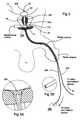
- FIG. 1is a schematic illustration of the anatomy of the male urethra showing a thermal ablation treatment region in the prostate.
- FIG. 2is a schematic illustration of the prostatic portion of the male urethra illustrating a stent in position in the subject after thermal ablation treatment and configured according to embodiments of the present invention.
- FIG. 2Ais an enlarged view of a region of the stent shown in FIG. 2 .
- FIG. 3is a schematic illustration of the prostatic portion of the male urethra illustrating an alternate embodiment of a stent in position according to embodiments of the present invention.
- FIGS. 3A and 3Bare enlarged views of a region of the stent illustrated in FIG. 3 .
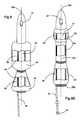
- FIG. 4is a front partial cutaway view of a stent similar to that shown in FIG. 2 illustrating the tissue anchoring balloon in a deflated configuration.
- FIG. 5Ais a front partial cutaway view of the stent shown in FIG. 4 illustrating the tissue-anchoring balloon inflated to an enlarged shape according to embodiments of the present invention.
- FIG. 5Bis a front view of an alternate embodiment of a stent similar to that shown in FIG. 5A illustrating the use of two conduits, one for inflating the anchoring balloon, and one for delivering medicaments, drugs, or rinses to the targeted (ablated prostatic tissue) while the stent is in position in the body according to embodiments of the present invention.
- FIG. 6Ais a front partial cutaway view of another embodiment of a stent similar to that shown in FIGS. 2-5A, and 5 B, but including an inflatable tissue molding intermediate portion.
- FIG. 6Bis a front partial cutaway view of an additional embodiment of a stent similar to that shown in FIGS. 2-5A, and 5 B but including a bladder (or distal) anchoring balloon.
- FIG. 6Cis an enlarged view of a region of the stent shown in FIG. 6 B.
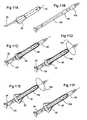
- FIG. 7Ais a front partial cutaway view of an alternate embodiment of a stent according to embodiments of the present invention.
- FIG. 7Bis a front partial cutaway view of the stent shown in FIG. 7A illustrating the lower anchoring balloon inflated to a ramped shape.
- FIG. 8is a front partial cutaway view of an additional embodiment of the present invention, illustrating a similar stent to that shown in FIGS. 7A and 7B with an intermediate tissue molding inflatable portion.
- FIG. 9Ais a front partial cutaway view of yet another embodiment of a stent according to embodiments of the present invention, illustrating a unitary body stent with both a bladder neck and tissue-anchoring balloon in the inflated position.
- FIG. 9Bis a front partial cutaway view of the stent shown in FIG. 9A showing the stent with only a single inflation conduit and the tissue and bladder neck anchoring balloons in the deflated state according to embodiments of the present invention.
- FIG. 9Cis an enlarged view of a region of the stent shown in FIG. 9 A.
- FIG. 10is a front partial cutaway view of another embodiment of a stent according to the present invention.
- FIG. 10Ais an enlarged view of a region of the stent shown in FIG. 10 .
- FIGS. 11A-11Fare a sequential series of figures which illustrate an operational sequence according to embodiments of the present invention.
- FIG. 11Ais a side view of a stent similar to that shown in FIGS. 2-5.
- FIG. 11Bis a side view of a pusher configured to be positioned inside of the stent to help position the stent in the body of the subject.
- FIG. 11Cis a side partial cutaway view of the stent shown in FIG. 11 A and the pusher shown in FIG. 11B, showing the tissue anchoring balloon in a deflated state and with the pusher insertion guide being inserted to and a portion of the pusher being inflatably transversely expanded to affix to the central lumen of the stent in preparation for guiding the stent through the penile meatus into the desired location in the prostate (or into other desired cavities or lumens) according to embodiments of the present invention.
- FIG. 11Dis a side partial cutaway view of the stent and guide shown in FIG. 11 C. This figure illustrates an anchoring balloon (on the pusher) inflated.
- FIG. 11Eis a side partial cutaway view of the stent and pusher shown in FIG. 11D which illustrates the stent anchoring balloon inflated after the guide-positioning balloon has been inflated and the desired position obtained.
- FIG. 11Fis a side partial cutaway view of the stent and pusher shown in FIG. 11E, illustrating the pusher or insertion guide fixation balloon deflated so the pusher can be removed from the stent, leaving the stent in position in the body.
- FIG. 12is a side enlarged partial section view of an alternate embodiment of a pusher or insertion guide and stent according to embodiments of the present invention.
- FIG. 12Ais an enlarged view of a region shown in FIG. 12 .
- FIG. 13Ais an enlarged side section view of a stent similar to that shown in FIGS. 9A and 9B.
- FIG. 13Bis an enlarged side section view of the stent shown in FIG. 13A with an alternate embodiment of a pusher/insertion guide positioned therein.
- FIG. 13Cis an enlarged view of a region of the stent shown in FIG. 13 A.
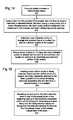
- FIG. 14is a block diagram of a method for inhibiting the obstruction of the prostatic urethra after thermal ablation according to the present invention.
- FIG. 15is a block diagram of a method for detaching a conduit from a catheter or stent when the stent is positioned in a subject according to embodiments of the present invention.
- FIG. 16is a block diagram of a method for treating BPH according to embodiments of the present invention.
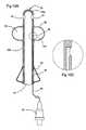
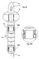
- FIG. 17is a front view of an alternate embodiment of a stent according to the present invention.
- FIG. 18is a front view of yet another embodiment of a stent according to the present invention.
- FIG. 18Ais an enlarged view of a region of the stent shown in FIG. 18 .
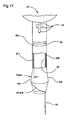
- FIG. 19is a front view of an additional embodiment of a stent according to the present invention.
- FIG. 19Ais an enlarged view of a region of the stent shown in FIG. 19 .
- thermal ablation treatment region 10is indicated by the lined region in the prostate 11 .
- the term “thermal ablation”refers to exposing the targeted tissue to a temperature which is sufficient to kill the tissue.
- the thermal ablationis carried out by exposing the targeted tissue to thermocoagulation via a catheter inserted into the subject which is configured to direct circulating hot liquid heated external of the body of the subject to the targeted treatment region.
- the tissueis exposed to an elevated temperature which is greater than or equal to about 45° C. for a predetermined period of time.
- other treatment typescan also be used such as surgical resection or other thermal therapies.
- the stents of the present inventionmay be appropriate for insertion in either treated or untreated natural lumens or body cavities such as blood vessels including arteries, the colon, the uterus, the cervix, the throat, the respiratory passages, the ear, the nose, and the like, to inhibit closure or restriction thereof.
- treated or untreated natural lumens or body cavitiessuch as blood vessels including arteries, the colon, the uterus, the cervix, the throat, the respiratory passages, the ear, the nose, and the like, to inhibit closure or restriction thereof.
- the thermal ablationis directed to treating BPH.
- the prostatic tissuecan be exposed to a temperature which is at or above about 50° C.-62° C. for a treatment period which is about 20-60 minutes.
- the treatment temperaturecan be at about 60° C.-62° C.
- temperatures of 45° C.-50° C.may be used.
- the BPH thermal ablation therapybe carried out in a localized treatment region within the prostatic urethra, the treatment region 10 being generally described as including the upper portion of the urethra in the prostatic urethra so as to extend generally below the bladder neck 12 a and above the verumontanum 11 b of the subject.
- the treatment region 10may include the bladder neck 12 a or a portion of the bladder neck itself.
- a suitable thermal treatment system and treatment catheterare available from ArgoMed, Inc. located in Cary, N.C. See also, U.S. Pat. Nos. 5,257,977 and 5,549,559 to Eshel, and co-assigned U.S. patent application Ser. No. 09/433,952 to Eshel et al, the contents of which are hereby incorporated by reference as if recited in full herein.
- the treatment catheteris left in position in the subject for an initial recovery period.
- This initial recovery periodcan be from about 12-72 hours, and preferably, about 24-48 hours. Leaving the treatment catheter in position for this initial period can reduce bleeding and subsequent blood clotting upon removal thereof.
- a post-treatment catheter or stent 20is inserted into the penile urethra via the penile meatus and into a desired position in the prostatic urethra 11 (FIG. 1) relative to the treatment region 10 .
- the stent 20can be used when desired and its use is not limited to post-therapeutic applications.
- the stent 20is a unitary body 20 b which has a length such that it extends above the sphincter 13 when in position in the subject.
- the stent 20also includes at least one fluid flow conduit or tube 25 having a length sufficient to extend from the stent body 20 b to a position which is external of the subject when the stent 20 is in position in the prostatic cavity.
- the conduit 25is configured with a shape and/or cross-sectional size, which is substantially smaller than the stent body cross-sectional size or width such that it is sufficiently small to allow normal function of the sphincter.
- the stent 20also includes a localized tissue-anchoring balloon 22 , which is in fluid communication with the conduit or tube 25 and a central lumen 23 .
- the stent 20is sized and configured to reside in the subject above the sphincter 13 . That is, unlike incontinence catheters or transurethral stent configurations, the unitary stent body 20 b of the present invention is configured to reside entirely above the spinchter 13 so that only one or more substantially smaller diameter (or cross-section) tube(s) 25 extend below the subject's sphincter to exit the penile meatus. As only one or more tubes 25 extend through the sphincter 13 , the stent 20 configuration allows natural operation of the sphincter 13 (i.e., the sphincter can close substantially normally with the stent 20 in position) thereby reducing the complexity and invasiveness of the device.
- the width or outer diameter of the stent body 20 bis about 6-9 mm and the conduit 25 is sized to be at least about 20-25 percent less than the cross-sectional width or outer diameter of the stent body, and more preferably the conduit has an outer cross-sectional width or diameter which is from about 0.5 mm-2.25 mm.
- the stent localized tissue anchoring balloon 22 or inflatable segmentis inflated via a fluid introduced through the conduit 25 to an expanded configuration.
- the anchoring balloon 22is adapted to engage with prostatic tissue (when deflated, the stent body 20 b preferably is configured as a smooth substantially constant profile body to allow for ease of insertion into the body).
- the stent 20is configured such that the tissue-anchoring balloon 22 engages with urethral tissue which is below the treatment region 10 but above the sphincter 13 , and more preferably in the membranous urethra, and most preferably between the sphincter 13 and the verumontanum 11 b.
- the tissue-anchoring balloon 22is preferably configured to take on a shape which can be described as a pear shape, ramped or inclined shape, or frusto-conical shape, when expanded. This allows the profile of the tissue-anchoring balloon 22 to taper out from the top to the bottom, thereby inhibiting movement of the stent 20 toward the sphincter 13 when the sphincter 13 relaxes or opens.
- this shapemay also inhibit upward movement of the stent body 20 b toward the treatment region 10 or bladder 12 , as the upper portion of the prostatic urethra, especially when the treated tissue is swollen, inflamed or suffering from edema, tends to close down or restrict the opening area in this region.
- the tapered anchoring balloon 22which can be positioned in the in the membranous urethra will abut the restricted size of the urethral canal thereabove, in the treatment region, thereby inhibiting upward movement or migration of the stent 20 .
- the present inventionis not limited thereto and other localized balloon shapes may also be employed such as bulbous, elliptical, oval, cylindrical, accordion pleated, tapered fins (such as circumferentially disposed about the perimeter of the lower portion of the stent body), and the like.
- the tissue-anchoring balloon 22is in fluid communication with the conduit 25 which is operatively associated with a valve 30 and a fluid inflation source (not shown).
- Valve 30is well known to those of skill in the art and are available from medical suppliers, such as Alaris Medical Systems of Creedmoor, N.C. and San Diego, Calif.
- inflation medialiquid, gas, or a mixture of one or more of liquid, gas and/or a powder or solid (which may dissolve after exposure to the gas or liquid) is directed into the conduit or tube 25 and up into the tissue anchoring balloon 22 .
- the stent body 20 bcan be configured with spaced apart tubular walls so that the gap between the walls form part of the inflation path (see e.g., FIG. 13 A).
- the conduit 25is directly connected with an opening 26 in the tubular wall of the stent body 20 b through which the inflation medium is directed.
- Suitable inflation mediainclude gas, liquids, or solids/powders or mixtures thereof, including, but not limited to, air, noble gases such as nitrogen and helium, oxygen, water, and oils (such as cannola oil, olive oil, and the like).
- the inflation mediumis selected to be non-toxic and to reduce any noxious effect to the subject should the balloon integrity be compromised, accidentally rupture, leak, or otherwise become impaired during service.
- a liquidor a substantially liquid media
- FIG. 4illustrates one embodiment of a stent 20 which includes externally visible indicia of the integrity of the inflated state of the lower inflatable portion 22 (inflation indicia can also be used to indicate the same about the bladder anchoring balloon 52 , or two can be used, one for each as shown in FIG. 9 A).
- this embodimentemploys an external balloon, which is in fluid communication with the valve 30 and the lower inflatable portion 22 and positioned relative to the stent 20 such that it is located outside the body when the stent is in position in the subject.
- the external indicator balloon 75is disposed proximate the valve 30 to provide a cushion between the valve and the penile meatus.
- inflation mediais directed into the conduit 25 through the valve 30 and an externally disposed balloon 75 .
- the external balloon 75inflates to a state which is representative of a fully inflatable state for the lower inflatable portion 22 .
- the valve 30is then closed and the external balloon 75 and the lower inflatable portion 22 are held in a desired inflated state. If the closed inflation system is compromised, the external balloon will deflate (reflecting the internal balloon has also been compromised and is deflating/deflated), and thus, provide a visually accessible means of identifying that the system is compromised.
- the means for externally visible indicia of the integrity of the inflated statecan be used for one or all of the inflatable balloons on the stent (shown here to indicate the inflated state of the lower anchoring balloon 22 ).
- the means for the externally visible indicia of the integrity of the inflated statecan be provided by other mechanisms, such as a “pop-up” indicator or sliding member operably associated with the valve 30 and the conduit 25 and/or a selected inflatable portion or balloon on the stent, the sliding member or indicator being configured to slide in a predetermined direction and present an externally visual indication when pressure in the closed inflation path (defined by the mechanism, the valve, the conduit, and the inflatable portion and/or balloon on the stent) drops below a threshold pressure level (not shown).
- Positive pressure valvesare available from the Halkey-Roberts Co.
- the stent body 20 bis conformably configured such that it can follow the contours of the urethra while having sufficient rigidity to maintain a sufficiently sized opening in the central lumen 23 to allow urine drainage and or flushing or drug delivery during the healing period while in position.
- the stent body 20 bis conformable but configured such that it is able to substantially maintain an opening in the central lumen when inserted and in position (and exposed to compressive swelling pressures in the localized treatment region) such that it maintains at least about 75% of the cross-sectional area, and preferably, at least about 90% or more of the cross-sectional area of central lumen 23 of the stent prior to insertion in the urethra.
- the cross-sectional shape of the lumenmay alter from the non-inserted shape, depending on the pressure distribution of the tissue surrounding and contacting same.
- the unitary tubular stent body 20 bis sufficiently conformable to yield to the contours of the subject's body as it is inserted therethrough into position in the prostate, yet sufficiently rigid to provide an open lumen when in position in the prostate and exposed to prostatic tissue which is exhibiting distress subsequent to undergoing thermal ablation therapy.
- the stent bodyis able to maintain a sufficient opening when exposed to compressive pressures from the treated tissue on the order of about 7-21 psi.
- the stent body 20 bis configured with a substantially uniform static body shape (non-inflatable) apart from the lower inflatable anchoring balloon 22 .
- the upper endis open and preferably includes a series of offset openings 24 formed in the stent tubular body 20 b and arranged around the perimeter thereof. This portion of the stent 20 enters the bladder and the additional openings 24 (apart from the central lumen 23 ) can facilitate urine entering into the central lumen 23 proximate the bladder 12 to travel through the stent body 20 b.
- the stent unitary body 20 bhas a wall thickness of about 1.0 mm and a central lumen size of about 4.7-7.0 mm.
- the stentis preferably produced in a plurality of lengths in a range of from about 3-12 cm, and more preferably from about 4-10 cm.
- the stents 20 of the present inventionare configured to reside above the spinchter 13 .
- FIG. 2also illustrates that the stent 20 may include external indicia of longitudinal movement which can alert the subject as to whether the stent 20 has migrated from its desired position.
- a series of graduation marks 25 gcan be attached to or formed on the external conduit.
- an appropriate indicia or marking 25 acan be applied to a graduation mark residing at a predetermined number of graduation marks outside the penile meatus.
- the subjectcan look at the applied graduation mark on the conduit 25 and recognize that it is migrating closer to the lumen entry point of the penile meatus; on the other hand, if the stent body 20 b moves toward the sphincter 13 , an increased number of markings will be visible and the conduit 25 with the applied mark 25 a will migrate away from the lumen entry point of the penile meatus.
- the subjectcan be alerted that upon identification of a movement over a certain number of graduation marks i.e., 1-10 (which can correspond with predetermined distances such as mm or cm), depending on the spacing of the marks, to notify his physician so that appropriate action may be taken.
- the movementmay indicate that healing is sufficient to allow removal altogether, or that undue physical activity may have exerted unusual forces onto the stent causing same to dislodge, such that removal and/or reinsertion may be required.
- the subjectmay be able to self-adjust the position of the stent body 20 b by merely pulling on the conduit until the applied marking 25 a once again resides at the appropriate number of marks away from the lumen entry.
- a “stopper”can be applied to the conduit on a portion which is located external to the subject.
- the “stopper”can be configured and sized to resist entry into the opening in the penile meatus thereby inhibiting undue inward travel of the stent body 20 b .
- the stoppercan have any number of configurations and can be integral to or separate from the conduit itself.
- the stoppercan be configured to be minimally invasive (non-irritating) to the user as it will be worn by same during use (not shown).
- the stent 20can also be configured with radiopaque markers to help identify its position for X-ray visualization.
- X-rayscan be taken at insertion/placement (initial positioning) and can also be taken periodically during the use of the stent or when there is a suspicion that the stent may have migrated from the desired location or merely to confirm proper positioning in the subject in situ.
- the radiopaque markers 77can be circumferentially arranged on the stent either or both above 77 u and below 77 l the localized tissue anchoring balloon 22 so that the anchoring balloon 22 can be more readily accentuated and confirmed in the X-ray as located in the membranous urethra, above the sphincter.
- one or more longitudinally extending radiopaque markers 77 acan be arranged to extend substantially along the length of the stent at various radial positions (preferably at least 4 symmetrically separated and aligned about the cross-sectional width of the stent, typically at 90 degree radial separation to allow for X-ray identification irrespective of the image angle).
- the radiopaque markersare applied to block the transmission of X-ray for better contrast in images.
- the opacity, degree of contrast, and sharpness of the imagemay vary with material and type of process used to create the marker.
- the radiopaque marker(s)may be arranged on the stent by any suitable biocompatible marker technique such as non-toxic radiopaque coatings, inks, thin-films, paints, tapes, strips, shrink tubing, and the like. See e.g., Richard Sahagian, Critical Insight: Marking Devices with Radiopaque Coatings , Medical Device & Diagnostic Industry (May, 1999), also available at URL http://www.devicelink.com/mddi/archive/99/01/011.html.
- radiopaque markersinclude polyolefin inks available as No-Tox® Medical Device Polyolefin Inks from Colorcon, and resin compounds with barium sulfate and/or bismuth such as is available from New England Urethane Inc. of North Haven, Conn. See also Danilychev et al., Improving Adhesion Characteristics of Wire Insulation Surfaces , Wire Technology International, March 1994 (discussing various treatments such as gas plasma treatment systems for medical products) which may be appropriate for use in the fabrication of the stent 20 .
- FIG. 5Billustrates that the stent 20 can include two conduits 25 a , 25 b , one in fluid communication with the lower inflatable anchoring balloon 22 and one in fluid communication with a medication delivery port 90 .
- Medication, drugs, treatments, rinses, and the likecan be introduced into the subject through an external medication port inlet 90 i .
- the fluid (or mixture)is then directed to exit the delivery port 90 on the stent 20 after the fluid travels through the conduit 25 b and released at the delivery port 90 .
- the medication port 90is operably associated with a distribution channel 90 c which extends circumferentially around the outer surface of the stent body 20 b so as to allow the fluid to flow therein to facilitate a broader dispersion of the released fluid.
- the medication inlet portcan be provided by any suitable valve/port device as is known to those of skill in the art. Suitable valve devices (for both the inflation system and the medication delivery system) are available from medical device manufacturers such as Alaris Medical Systems (SmartSite® system) and B. Braun. The medication can be used to reduce edema, inhibit bacterial infections, reduce the likelihood of UTI or treat the onset of UTI or otherwise promote healing and/or treatment.
- Suitable valve devicesfor both the inflation system and the medication delivery system
- the medicationcan be used to reduce edema, inhibit bacterial infections, reduce the likelihood of UTI or treat the onset of UTI or otherwise promote healing and/or treatment.
- FIG. 5Balso shows the conduits 25 a , 25 b , relative to the sphincter illustrating (in dotted line) the inward movement of the conduits relative to the stent body 20 b when in position, allowing the sphincter to function substantially normally when the stent 20 is proper position in situ.
- FIG. 6Aillustrates a stent 20 similar to that shown in FIGS. 4 and 5, but having an inflatable tissue-molding portion 42 above the tissue-anchoring portion 22 .
- the inflatable tissue molding portion 42is configured to extend proximate the treatment region 10 when the stent 20 is in position in the subject.
- the tissue-molding portion 42can be substantially cylindrical when expanded to mold the opening in the treated region of the prostatic urethra to a width or outer diameter commensurate therewith as the ablated tissue heals to an increased opening size, prolonging the successful life of the treatment.
- the inflatable tissue-molding portion 42is sized such that when inflated it presents an outer diameter or width of about 15-25 mm.
- the inflatable tissue molding portion 42 as well as the tissue-anchoring balloon 22can be configured to be in fluid communication with the conduit or tube 25 .
- a fluid flow channel 44can be formed in the walls of the stent body 20 b intermediate the two inflatable portions 22 , 42 , in a manner similar to that discussed above, or a bridging conduit (not shown) can be used to bridge the two inflatable balloon segments 22 , 42 and be in fluid communication with the tube 25 .
- a bridging conduit(not shown) can be used to bridge the two inflatable balloon segments 22 , 42 and be in fluid communication with the tube 25 .
- an additional tubecan be added to inflate/deflate the inflatable tissue portion 42 such that the tissue-anchoring balloon 22 is in fluid isolation from the inflatable tissue portion 42 (such as shown in FIG. 9A for an alternative inflatable arrangement).
- FIG. 6Billustrates that the open-ended stent 20 shown, for example, in FIG. 4, can alternatively (or in addition to) include an upper anchoring balloon 52 which is configured to reside against the bladder neck when in position and inflated.
- this embodimentemploys two separate conduits 25 a , 25 b , allowing the two balloons 22 , 52 to be separately inflated and deflated.
- FIGS. 7A and 7Billustrate an additional embodiment of a stent 20 according to the present invention.
- the stent 20includes a closed end portion 20 e with at least one opening 27 formed spaced apart from the tip, the closed end portion 20 e being adapted to be positioned in the bladder 12 to allow fluids to be flushed through the at least one opening (including drug delivery as needed) and/or to allow urine to drain therefrom.
- the stent 20includes a unitary body 20 b which is configured to reside in the prostate such that the tissue anchoring balloon 22 is located below the treated region 10 and the non-inflatable shaft portion 20 n of the stent body 20 b extends along the treatment region 10 .
- FIG. 8illustrates that the stent 20 may also include an inflatable tissue portion 42 which is positioned intermediate the closed end 20 e and the tissue-anchoring balloon 22 as discussed above.
- FIGS. 3, 9 A, and 9 Billustrate yet another embodiment of the present invention.
- the stent 20includes an upper bladder-anchoring balloon 52 as well as the (lower) tissue-anchoring balloon 22 .
- the bladder-anchoring balloon 52resides against the bladder neck of the subject, thereby securely positioning the stent 20 in the prostate relative to the bladder 12 .
- the tissue-anchoring balloon 22 located on the other opposing end portion of the stentinhibits movement toward the bladder (thus providing bilateral anchoring in the prostate).
- the intermediately located non-inflatable portion 20 n of the stent shaft or body 20 bis located adjacent the treatment region 10 .
- the stent body 20 bmay have a length which is greater than the open-end length as it is configured to enter the bladder.
- the length of the stent body 20 b below the upper balloon 52may be provided in several sizes from about 3-12 cm, and preferably from about 4-10 cm.
- the same reasoningcan be applied to the closed end embodiments shown for example in FIGS. 7A, 7 B, and 8 (that is, the length of the stent 20 below the closed end portion and drainage eye(s) 27 may be on the same order as that described above).
- the upper anchoring balloon 52is separately inflatable to allow this balloon 52 to be inflated before the lower balloon 22 . This can reduce the likelihood that the upper balloon 52 will be inflated below the desired location (potentially introducing damage to the bladder neck or the upper portion of the prostatic urethra) and facilitate proper positioning of the stent 20 in the prostate relative to the bladder and above the sphincter 13 .
- FIG. 9Aillustrates two conduits 25 a , 25 b extend from the stent body 20 b , each in fluid communication with a corresponding upper or lower balloon 52 , 22 , respectively.
- FIG. 9Billustrates the stent 20 with both the upper and lower anchoring balloons 52 , 22 in a deflated state.
- a single tube 25is used to inflate both the upper and lower balloons 52 , 22 through a fluid opening positioned relative to each one 26 .
- FIG. 9Aalso illustrates another embodiment of the present invention.
- a conduit 225is releasably attached to the stent body 20 b and is in fluid communication with the upper anchoring balloon 52 .
- the stent 20is inserted into position as described above, and the upper anchoring balloon 52 is inflated through conduit 225 to position the stent in a desired location relative to the bladder neck landmark.
- the lower balloon 22is then inflated to hold the stent 20 in position above the sphincter 13 .
- a tensile force shown by the arrow labeled “F pull ”is applied to remove the conduit 225 and deflate the anchoring balloon 52 .
- the conduit 225 and/or valve 30 operably associated therewithwhich is configured to releasably detach from the stent 20 is conspicuously identified by an identifier 225 i so that an operator may easily identify the proper conduit to which to apply the release force to.
- the releasable conduit 225 and/or its associated valve member 30can be striped, labeled, painted, colored, or otherwise configured with visually apparent indicia.
- Any suitable attachment meanscan be used to releasably secure the conduit 225 to the stent body 20 b , such as mechanical or chemical means including, but not limited to, adhesives, heat bonding, chemical, or UV cured bonding of the conduit 225 to the stent body 20 b so as to releasably attach to the stent body 20 b .
- the attachmentcan be located at any suitable location along the stent body 20 b or at the fluid entry 26 to the upper balloon 52 , but is preferably arranged such that it is along the inner wall of the stent body to provide for easier insertion and protect it from handling degradation and/or stress or punctures.
- the releasable attachmentis configured so as to remain attached when exposed to small tensile or torsional forces typical of handling and at insertion, but yields at tensional forces above about 2-10N.
- attachment systemsinclude PlasticWeld Systems Catheter Manufacturing Equipment from Plastic Weld Systems located in Nefane, N.Y.; the NovacureTM (referencing U.S. Pat. No.
- UV 75and the Ultracure 100SS Plus all from EFOS Inc, of Mississauga, Canada; the Green Spot UV Cure System from UV Source Inc, of Torrance, Calif.; the Medi-CureTM MC Curing Spot and Flood Lamps (and other products) from DYMAX Corporation located in Torrington, Conn.
- Suitable UV adhesivesare well known in the art. Examples include CTH adhesives known as model numbers 201 through 204 CTH, available from DYMAX Corporation of Torrington, Conn., and Permabond Adhesives for the medical device industry from Permabond Engineering Adhesives located in Englewood, N.J.
- FIG. 10illustrates the embodiments of FIGS. 3, 9 A or 9 B with a third inflatable portion, an intermediate inflatable tissue molding segment 42 as discussed for other embodiments above.
- this embodimentmay include one, two, or three or more conduits 25 .
- this stent 20includes two conduits 25 a , 25 b configured such that the upper balloon 52 is in fluid isolation from the remaining intermediate and lower balloons 42 , 22 .
- the conduit 25 b shown for the upper balloon 52may be configured to be releasably detachable from the stent body 20 b once the stent 20 is in the desired location in the prostate.
- the conduit 25is substantially smaller in cross-sectional width than relative to the cross-sectional width of the stent body 20 b.
- the stent body 20 bmay be configured with alternate tissue-anchoring means. As shown, the lower portion of the stent body 20 b tapers 22 t laterally outwardly a distance relative to the upper portion. In certain embodiments, this taper can be configured such that the outer wall 20 o increases no more than about 7 degrees radially outward along the taper profile line (shown by the arrows drawn from the outer surface to the inner wall 20 i ). This embodiment also illustrates that the bottom of the stent body 20 b can have a diagonal shape, i.e., is angled 20 ang across the width of the stent body 20 b . As is also shown, the stent body 20 b can include a drug delivery port 90 thereon.
- the port 90is in fluid communication with at least one fluid conduit 25 which can direct a rinse, medicament, or other fluid thereto.
- the stent body 20 bcan have at least one liquid channel 90 c formed circumferentially therearound.
- the liquid channel 90 cis preferably in fluid communication with the drug delivery port 90 .
- a saline or other biocompatible non-toxic rinse, or drug, treatment substance, or medicamentcan be directed into the conduit and out of the port 90 and into the channel 90 c .
- the channel 90 ccan thus distribute the liquid around the treatment region, which if merely ejected from the port may be localized to the region facing the port.
- the liquid channel 90 ccan be notched into the stent body or a region on the stent body 20 b , which has a reduced wall thickness relative to one or more of the adjacent upper and lower portions of the stent body.
- the delivery port 90may be also a plurality of ports circumferentially and/or axially spaced apart about the perimeter of the stent body 20 b (not shown).
- FIG. 18illustrates another tissue anchoring means, a plurality of inflatable portions 322 .
- the plurality of inflatable portions 322present a ribbed or ridged profile which engages with the urethra and inhibits movement upward when in position. It is noted that, although shown as a series of aligned and serially connected frusto-conical inflatable portions 322 , other shapes and configurations can also be employed to present a ribbed or ridged profile.
- the bladder-anchoring balloon 52inhibits movement, and more particularly, is shaped and oriented in this embodiment to inhibit downward movement.
- the inflatable portions 322can be configured on the stent body 20 b such that they extend only about a portion of the length of the stent body 20 b . For example, so that a plurality of inflatable portions 322 are located only about the bottom portion of the stent body (not shown).
- FIG. 19illustrates yet another embodiment of a stent 20 according to the present invention.
- this embodimentincludes an increased elastic portion 190 disposed about the stent body 20 b such that it is above the lower anchoring balloon 22 (or lower anchoring means).
- the increased elastic portion 190can be formed in a number of ways so as to allow tensional stretch (or collapse) in the stent body 20 b to help locate and/or position the stent 20 in the desired location.
- this regioncan be configured from a different material relative to the adjacent upper and lower regions of the stent body 191 u , 191 l , a notched region, a reduced wall thickness region, or by introducing symmetrically spaced windows about the circumference of the stent body 20 b .
- the stent body 20 bmay be pulled upward while the tissue-anchoring balloon is pulled downward. Therefore, introducing an elastic portion 190 between the two balloons, 52 , 22 , respectively, can allow the stent body to stay positioned in its desired location with enough stretch as to inhibit the introduction of undue tensile forces onto the stent body between the two balloons 52 , 22 which can be caused by the configuration of the anatomy of the subject.
- the elastic portion 190may also inhibit the introduction of unnecessary opposing locational forces of the respective balloons 52 , 22 onto the surrounding tissue (i.e., a downward force onto the bladder neck and an upward force at the membranous urethra proximate or the prostatic urethra).
- the elastic portion 190can also be configured to act as the medication/rinse channel 90 c as discussed above.
- the stentcan resides in the body for between 2-14 days (and potentially even longer), surface or other treatments may also be applied to, or integrated into, the stent 20 to achieve one or more of increased lubricity, low coefficient of friction (each for easier insertion) as well as increased tissue biocompatibility such as resistance to microbial growth and/or configured to reduce the incidence of UTI.
- the stent body 20 bcomprises a material, at least on its exposed surfaces, which can inhibit the growth of undesirable microbial organisms while the stent 20 is held in the body during the healing period as noted herein.
- the stentis coated with a biocompatible antimicrobial solution or coating which can inhibit the growth of bacteria, yeast, mold, and fungus.
- a biocompatible antimicrobial solution or coatingwhich can inhibit the growth of bacteria, yeast, mold, and fungus.
- One suitable materialmay be the antimicrobial silver zeolite based product available from HealthShield Technologies LLC of Wakefield, Mass.
- Another alternativeis a Photolink® Infection Resistance antimicrobial coating or a hemocompatible coating from SurModics, Inc. of Eden Prairie, Minn.
- the coatingmay also include other bioactive ingredients (with or without the antimicrobial coating), such as antibiotics, and the like.
- One productis identified as LubriLASTTM lubricious coatings from AST of Billerica, Mass.
- the stentcan be configured with a biocompatible lubricant or low-friction material to help reduce any discomfort associated with the insertion of the device into the body.
- Coatingswhich may be appropriate include coatings which promote lubricity, and wettability.
- a hydrophilic coatingwhich is applied as a thin (on the order of about 0.5-50 microns thick) layer which is chemically bonded with UV light over the external surface of the stent 20 .
- Hydrolene®available from SurModics, Inc., of Eden Prairie, Minn.
- Other similar productsare also available from the same source.
- the stent 20can be configured not only to provide the lubricious coating but to also include bioactive ingredients configured to provide sustained release of antibiotics, antimicrobial, and anti-restenosis agents, identified as LubrilLastTM from AST as noted above.
- FIGS. 11A-11Fillustrate a sequential series of operative deployment of the stent 20 into the body of the subject.
- FIG. 11Aillustrates the stent 20 .
- FIG. 11Billustrates one embodiment of a pusher or insertion guide 120 configured to extend through the central lumen 23 of the stent and used to insert the stent 20 into position in the subject.
- the insertion guide or pusher 120includes at least one outwardly expandable fixation balloon(s) 136 and an anchoring or positioning balloon 152 positioned on a distal end portion thereof.
- the fixation balloonmay be single balloon which is elongated and extend along the length of the stent body 20 b or, as shown, may be a single localized fixation balloon located to engage with a distal or upper portion of the stent body 20 b .
- a plurality of fixation balloonsmay also be used (not shown).
- the guide 120also includes an elongated body, which is substantially longer than the stent body 20 b.
- FIG. 11Cillustrates the insertion guide 120 inserted into the stent 20 such that the upper or distal end portion of the guide 120 extends through the open distal end of the stent 20 .
- the fixation balloon 136is then inflated to snugly hold the stent 20 affixed to the insertion guide 120 .
- the elongated insertion guide 120has a length which extends a distance out of the bottom or proximal end of the stent.
- the conduit 25can reside along the outer perimeter of the insertion guide or can reside in a groove configured to hold same therein during insertion into the body.
- the guide 120 inflatable (bladder) anchoring balloon 152is expanded after the guide 120 and stent 20 are in position in the subject (such as in the prostate).
- the local tissue-anchoring balloon on the stent 22is then inflated.
- the guide upper anchoring balloon 152 and fixation balloon 136are deflated so that the guide 120 can be slidably removed from the stent 20 leaving the stent in position (in the prostate).
- Other suitable guides and or pushersare well known to those of skill in the art.
- the stentincludes spaced apart walls 20 w 1 , 20 w 2 which may help retain the desired conformable stent configuration in operative use. That is, the stent 20 is configured to be conformable to the contours of the urethra upon insertion but is also sufficiently rigid to hold the central lumen size to a size which is substantially the same in the prostate as when the stent is external of the subject (i.e., it does not collapse to close off the passage or central lumen in response to the pressure of the ablated tissue in the prostate).
- the two spaced apart walls 20 w 1 , 20 w 2may also be connected with interconnecting structural baffle or support means, particularly in the portion which is configured for placement in the treatment region (not shown). See e.g., co-pending and co-assigned U.S. Provisional Patent App. Ser. No. 60/248,109, the contents of which are hereby incorporated by reference as if recited in full herein.
- the conduit 25can be attached to the stent body 20 b to direct inflation medium or fluid into the gap between the walls, or the conduit 25 can be attached to enter the external wall 20 w 1 to inflate the lower balloon 22 .
- the guide 120is configured with two separately inflatable portions: the elongated portion 136 , which expands to affix to the inner surface of the inner wall 20 w 2 ; and the upper anchoring balloon 152 . As shown, the guide 120 is also configured with a closed end but includes drainage and or flushing orifices 127 above the anchoring balloon 152 . In operation, the guide 120 delivers the inflation medium into an inlet/outlet or port 136 i in fluid communication with the fixation balloon portion through a valve 230 and associated inflation source 236 . Similarly, to anchor the stent and guide in the prostate at the bladder neck, the upper anchoring balloon 152 on the guide is expanded via fluid entering the port 126 (and subsequently leaving upon deflation).
- Fluidis directed from an inflation medium through a valve 230 ′ and an associated inflation source 252 .
- the guide 120includes a central drainage lumen 123 which is in fluid communication with the bladder of the subject (when in operative position) and is configured to drain and/or flush fluids therebetween.
- FIG. 13Aillustrates an embodiment similar to that shown in FIGS. 9A and 9B.
- the stent 20is configured with the upper anchoring balloon 52 , so the inflatable guide 120 ′ (FIG. 13B) includes an open end with a drainage lumen 123 therethrough.
- the inflatable guide 120 ′(FIG. 13B) includes an fixation segment or balloon 136 as discussed under the embodiment shown in FIG. 12, but only one valve 230 and associated guide inflation source is needed.
- the guide fixation balloon portion 136can be deflated and the guide 120 ′ easily slidably removed from the stent 20 , leaving the stent 20 in its desired position in the body fixed relative to the bladder and residing above the sphincter, as discussed above.
- guide wire or stylet placement systemsare well known. Guide wires are typically used with a stent having an open end such as shown in FIG. 2, while stylets are used with closed end or tips (such as shown in FIG. 3) to inhibit the stylet from contacting the urethra and potentially causing injury thereto.
- closed end configurations of the stent 20 shown hereinhave been illustrated as substantially upright, they can also be curved into other configurations such as Coude or Tiemen.
- FIG. 14a method for inhibiting the obstruction of the prostatic urethra after thermal ablation (or resection or other procedure) according to the present invention, is shown.
- a prostatic tissueis treated such as thermally ablated (Block 400 ).
- a stenthaving a unitary body with a first cross-sectional area, and a conduit attached thereto, the conduit having a second cross-sectional area, the second cross-sectional area being substantially less than the first, is inserted into the penile meatus and up along the penile urethra until the body of the stent is positioned in a desired location such that it resides in the prostate above the sphincter (Block 410 ).
- a (lower) tissue-anchoring balloonis inflated to secure the stent in the desired location (Block 420 ). After a period of about 2-14 days, the stent lower anchoring balloon is deflated and the stent is removed by pulling on an externally exposed end of the conduit (Block 430 ).
- FIG. 15is a block diagram of a method for detaching a conduit from a catheter or stent when the stent is positioned in a subject.
- a stent with a releasably attached or detachable conduitis inserted into the natural lumen of the body such that a portion of the conduit remains external of the subject (Block 500 ).
- a tensile forceis exerted onto the detachable conduit (by pulling the exposed portion of the conduit), forcing the conduit to detach from the catheter or stent while leaving the stent in position in the body (Block 510 ).
- the detachable conduitis in fluid communication with a bladder-anchoring balloon and the bladder-anchoring balloon deflates responsive to the detachment of the first conduit.
- the stentcan include a second conduit separate from the first which is configured to direct an inflation media (preferably comprising a liquid) into a lower inflatable segment on the stent when the first conduit is detached.
- an inflation mediapreferably comprising a liquid
- the bladder neck-anchoring balloonis inflated after insertion for positioning the stent in the subject relative to the bladder neck (where the bladder anchoring balloon resides).
- the positioning stepwill be carried out such that the stent body is positioned above the sphincter and the lower anchoring means (such as the lower balloon) is located between the verumontanum and the sphincter (in the membranous urethra).
- the lower anchoring meanssuch as the lower balloon
- the lower inflatable memberis inflated. It is subsequent to this second inflation that the detachable conduit is removed.
- FIG. 16is a block diagram of a method for treating BPH according to embodiments of the present invention.
- the methodincludes inserting a treatment catheter configured to circulate heated liquid into the prostate of the subject (Block 600 ) and then circulating liquid heated to above 45° C. (Block 610 ).
- the circulating heated liquidis directed through the catheter to a treatment balloon such that it travels, captured in the catheter, through the penile meatus, along the penile urethra the bulbous urethra, and the membranous urethra to a localized treatment region in the prostate (Block 620 ).
- the tissue in the localized treatment region in the prostateis exposed to a temperature above about 45° C.
- the localized treatment regioncan be an upper portion of the prostatic urethra, leaving the urethra below the prostatic urethra about the membranous urethra, non-ablated. This is accomplished, in circulating systems, which heat remotely, by insulating the shaft of the treatment catheter up to the treatment balloon to inhibit the exposure of non-targeted tissue to ablation temperatures.
- the circulating fluidcan be heated to lower treatment temperatures, such as less than 45° C. (such as 35° C.-44° C.) or may be cooled to provide cooling at the localized tissue region.
- the circulating heated wateris partially (and preferably, totally) removed from the treatment catheter.
- the treatment cathetermay be left in position in the subject for an initial portion of the healing process (the initial portion including about the first 12-72 hours, and more preferably about 24-48 hours) (shown by broken line to indicate that this is optional) (Block 640 ). This delay in removal of the treatment catheter can reduce the likelihood or amount of bleeding and subsequent blood clotting caused by premature removal of the treatment catheter.
- a tissue-molding stentis inserted into the prostate immediately after the thermal treatment or after a delay (Block 650 ).
- the stentcan be anchored in position in the prostate by inflating a localized balloon portion thereon such that it engages with the tissue of the subject and allows normal operation of the sphincter (Block 660 ).
- the post-treatment stentis removed from the subject, after the tissue anchoring balloon (and as applicable, the bladder anchoring balloon) is deflated, typically after about 2-14 days from insertion (Block 670 ).
- the releasable or detachable attachment configurations as well as the elastic region and other features of the stents of the instant inventionmay be applied to other catheter or stent configurations, as well as to guides or pushers for placing and locating catheters and/or stents.
- the detachable conduitscan be tubular, as shown, or can be alternatively configured, such as a line, string, linkage, or other small cross-sectional member which has a length which makes it externally accessible when the stent or guide is in the body.
- the detachable or releasable line or conduitmay also be used for other applications such as for catheters, guides, or stents and the like configured for insertion in natural lumens or body cavities such as blood vessels (including, but not limited to, arteries), the rectum, the colon, the cervix and/or uterus, the bladder, the throat, the ear, the nose, passages of the heart and/or associated valves, the respiratory system, the esophagus, and the like.
Landscapes
- Health & Medical Sciences (AREA)
- Life Sciences & Earth Sciences (AREA)
- Heart & Thoracic Surgery (AREA)
- Biomedical Technology (AREA)
- Animal Behavior & Ethology (AREA)
- Pulmonology (AREA)
- Engineering & Computer Science (AREA)
- Anesthesiology (AREA)
- Child & Adolescent Psychology (AREA)
- Hematology (AREA)
- Biophysics (AREA)
- General Health & Medical Sciences (AREA)
- Public Health (AREA)
- Veterinary Medicine (AREA)
- Media Introduction/Drainage Providing Device (AREA)
- Thermotherapy And Cooling Therapy Devices (AREA)
- Surgical Instruments (AREA)
- External Artificial Organs (AREA)
Abstract
Description
Claims (22)
Priority Applications (6)
| Application Number | Priority Date | Filing Date | Title |
|---|---|---|---|
| US09/837,486US6716252B2 (en) | 2000-06-30 | 2001-04-18 | Prostatic stent with localized tissue engaging anchoring means and methods for inhibiting obstruction of the prostatic urethra |
| PCT/US2001/015585WO2002002032A2 (en) | 2000-06-30 | 2001-05-15 | Prostatic stent with localized tissue engaging anchoring means |
| CA002412774ACA2412774A1 (en) | 2000-06-30 | 2001-05-15 | Prostatic stent with localized tissue engaging anchoring means and methods for inhibiting obstruction of the prostatic urethra |
| EP01937379AEP1296737A2 (en) | 2000-06-30 | 2001-05-15 | Prostatic stent with localized tissue engaging anchoring means |
| JP2002506660AJP2004513679A (en) | 2000-06-30 | 2001-05-15 | Prostate stent with local tissue engaging means and method for preventing occlusion of the prostatic urethra |
| AU2001263122AAU2001263122A1 (en) | 2000-06-30 | 2001-05-15 | Prostatic stent with localized tissue engaging anchoring means |
Applications Claiming Priority (2)
| Application Number | Priority Date | Filing Date | Title |
|---|---|---|---|
| US21515600P | 2000-06-30 | 2000-06-30 | |
| US09/837,486US6716252B2 (en) | 2000-06-30 | 2001-04-18 | Prostatic stent with localized tissue engaging anchoring means and methods for inhibiting obstruction of the prostatic urethra |
Publications (2)
| Publication Number | Publication Date |
|---|---|
| US20020032486A1 US20020032486A1 (en) | 2002-03-14 |
| US6716252B2true US6716252B2 (en) | 2004-04-06 |
Family
ID=26909762
Family Applications (1)
| Application Number | Title | Priority Date | Filing Date |
|---|---|---|---|
| US09/837,486Expired - Fee RelatedUS6716252B2 (en) | 2000-06-30 | 2001-04-18 | Prostatic stent with localized tissue engaging anchoring means and methods for inhibiting obstruction of the prostatic urethra |
Country Status (6)
| Country | Link |
|---|---|
| US (1) | US6716252B2 (en) |
| EP (1) | EP1296737A2 (en) |
| JP (1) | JP2004513679A (en) |
| AU (1) | AU2001263122A1 (en) |
| CA (1) | CA2412774A1 (en) |
| WO (1) | WO2002002032A2 (en) |
Cited By (48)
| Publication number | Priority date | Publication date | Assignee | Title |
|---|---|---|---|---|
| US20020165521A1 (en)* | 2001-05-04 | 2002-11-07 | Iulian Cioanta | Low thermal resistance elastic sleeves for medical device balloons |
| US20040267340A1 (en)* | 2002-12-12 | 2004-12-30 | Wit Ip Corporation | Modular thermal treatment systems with single-use disposable catheter assemblies and related methods |
| US20050013876A1 (en)* | 2001-09-25 | 2005-01-20 | Mccloskey Jenny Colleen | Inactivation of papillomavirus |
| US20050020976A1 (en)* | 2003-06-18 | 2005-01-27 | Terumo Kabushiki Kaisha | Medical therapeutic apparatus |
| US20050107735A1 (en)* | 1998-10-15 | 2005-05-19 | Scimed Life Systems, Inc. | Treating urinary retention |
| US20050165378A1 (en)* | 2002-04-16 | 2005-07-28 | Russell Heinrich | Method and apparatus for anastomosis including an expandable anchor |
| US20060129136A1 (en)* | 2004-12-09 | 2006-06-15 | Meacham George B K | Catheter |
| US20070287956A1 (en)* | 2003-09-24 | 2007-12-13 | Tal Michael G | Method and apparatus for treatment of thrombosed hemodialysis access grafts and arterio venous fistulas |
| US20080033570A1 (en)* | 2003-08-01 | 2008-02-07 | Blitz Benjamin T | Prostatic stent placement device |
| US20090216206A1 (en)* | 2006-10-17 | 2009-08-27 | C. R. Bard, Inc. | Waste Management System |
| US20090277457A1 (en)* | 2008-05-06 | 2009-11-12 | Michael Hoey | Systems and methods for male sterilization |
| US20100145325A1 (en)* | 2008-11-06 | 2010-06-10 | Michael Hoey | Systems and Methods for Treatment of Prostatic Tissue |
| US20100145326A1 (en)* | 2008-11-06 | 2010-06-10 | Michael Hoey | Systems and Methods for Treatment of BPH |
| US20100145254A1 (en)* | 2008-11-06 | 2010-06-10 | Shadduck John H | Systems and Methods for Treatment of Prostatic Tissue |
| US20100179528A1 (en)* | 2009-01-14 | 2010-07-15 | Shadduck John H | Systems and Methods for Treatment of Prostatic Tissue |
| US20100179416A1 (en)* | 2009-01-14 | 2010-07-15 | Michael Hoey | Medical Systems and Methods |
| US20100286717A1 (en)* | 2002-04-17 | 2010-11-11 | Tyco Healthcare Group Lp | Method and Apparatus for Anastomosis Including an Expandable Anchor |
| US20100292767A1 (en)* | 2009-04-27 | 2010-11-18 | Michael Hoey | Systems and Methods for Prostate Treatment |
| US20100298948A1 (en)* | 2009-04-27 | 2010-11-25 | Michael Hoey | Systems and Methods for Prostate Treatment |
| US20110238144A1 (en)* | 2010-03-25 | 2011-09-29 | Michael Hoey | Systems and Methods for Prostate Treatment |
| US8465551B1 (en) | 2011-07-09 | 2013-06-18 | Bandula Wijay | Temporary prostatic stent for benign prostatic hyperplasia |
| US8777912B2 (en) | 2007-07-22 | 2014-07-15 | C. R. Bard, Inc. | Waste management system |
| US20140336574A1 (en)* | 2011-12-16 | 2014-11-13 | Musc Foundation For Research Development | Double balloon catheter |
| US9561067B2 (en) | 2008-10-06 | 2017-02-07 | Virender K. Sharma | Method and apparatus for tissue ablation |
| US9561066B2 (en) | 2008-10-06 | 2017-02-07 | Virender K. Sharma | Method and apparatus for tissue ablation |
| US9561068B2 (en) | 2008-10-06 | 2017-02-07 | Virender K. Sharma | Method and apparatus for tissue ablation |
| US9700365B2 (en) | 2008-10-06 | 2017-07-11 | Santa Anna Tech Llc | Method and apparatus for the ablation of gastrointestinal tissue |
| US9895185B2 (en) | 2011-09-13 | 2018-02-20 | Nxthera, Inc. | Systems and methods for prostate treatment |
| US9968395B2 (en) | 2013-12-10 | 2018-05-15 | Nxthera, Inc. | Systems and methods for treating the prostate |
| US20180133042A1 (en)* | 2015-07-13 | 2018-05-17 | Jotec Gmbh | Balloon catheter |
| US10064697B2 (en) | 2008-10-06 | 2018-09-04 | Santa Anna Tech Llc | Vapor based ablation system for treating various indications |
| US10194970B2 (en) | 2013-12-10 | 2019-02-05 | Nxthera, Inc. | Vapor ablation systems and methods |
| US10335222B2 (en) | 2012-04-03 | 2019-07-02 | Nxthera, Inc. | Induction coil vapor generator |
| US10342593B2 (en) | 2015-01-29 | 2019-07-09 | Nxthera, Inc. | Vapor ablation systems and methods |
| US10695126B2 (en) | 2008-10-06 | 2020-06-30 | Santa Anna Tech Llc | Catheter with a double balloon structure to generate and apply a heated ablative zone to tissue |
| US10702327B2 (en) | 2015-05-13 | 2020-07-07 | Boston Scientific Scimed, Inc. | Systems and methods for treating the bladder with condensable vapor |
| US10751107B2 (en) | 2017-01-06 | 2020-08-25 | Boston Scientific Scimed, Inc. | Transperineal vapor ablation systems and methods |
| US10772670B2 (en) | 2013-03-14 | 2020-09-15 | Boston Scientific Scimed, Inc. | Systems and methods for treating prostate cancer |
| US11090036B2 (en)* | 2005-05-20 | 2021-08-17 | Neotract, Inc. | Devices, systems and methods for treating benign prostatic hyperplasia and other conditions |
| US11246640B2 (en) | 2016-12-21 | 2022-02-15 | Boston Scientific Scimed, Inc. | Vapor ablation systems and methods |
| US11331140B2 (en) | 2016-05-19 | 2022-05-17 | Aqua Heart, Inc. | Heated vapor ablation systems and methods for treating cardiac conditions |
| US11504149B2 (en) | 2005-05-20 | 2022-11-22 | Teleflex Life Sciences Limited | Median lobe destruction apparatus and method |
| US11648380B2 (en) | 2017-12-05 | 2023-05-16 | Jenny Colleen McCloskey | Device for treatment of a body canal and adjacent surfaces |
| US11806066B2 (en) | 2018-06-01 | 2023-11-07 | Santa Anna Tech Llc | Multi-stage vapor-based ablation treatment methods and vapor generation and delivery systems |
| US11850140B2 (en) | 2013-03-14 | 2023-12-26 | Teleflex Life Sciences Limited | Devices, systems and methods for treating benign prostatic hyperplasia and other conditions |
| US12121228B2 (en) | 2017-12-23 | 2024-10-22 | Teleflex Life Sciences Llc | Expandable tissue engagement apparatus and method |
| US12364537B2 (en) | 2016-05-02 | 2025-07-22 | Santa Anna Tech Llc | Catheter with a double balloon structure to generate and apply a heated ablative zone to tissue |
| US12440258B2 (en) | 2023-11-20 | 2025-10-14 | Boston Scientific Scimed, Inc. | Systems and methods for treating prostate cancer |
Families Citing this family (39)
| Publication number | Priority date | Publication date | Assignee | Title |
|---|---|---|---|---|
| WO2004012628A1 (en)* | 2002-08-05 | 2004-02-12 | Uri Rosenschein | Embolism filter with self-deployable guidewire stop |
| DE10255344A1 (en)* | 2002-11-27 | 2005-06-30 | Siemens Ag | Conveyor system for goods, in particular containers for luggage, and control system for the conveyor system |
| US7025768B2 (en)* | 2003-05-06 | 2006-04-11 | Boston Scientific Scimed, Inc. | Systems and methods for ablation of tissue |
| EP1653854A1 (en)* | 2003-08-04 | 2006-05-10 | Ditens A/S | Apparatus for detecting gastric motility |
| US7766899B2 (en)* | 2003-09-17 | 2010-08-03 | Prostalund Operations Ab | Partial-length, indwelling prostatic catheter using coiled inflation tube as an anchor and methods of draining urine and flushing clots |
| US7662145B2 (en)* | 2003-09-17 | 2010-02-16 | Prostalund Operations Ab | Partial-length indwelling urinary catheter and method permitting selective urine discharge |
| JP3892438B2 (en)* | 2003-12-26 | 2007-03-14 | 株式会社日本メディックス | Heating balloon catheter device and its elastic tube device |
| US8123762B2 (en) | 2004-08-19 | 2012-02-28 | Boston Scientific Scimed, Inc. | Suturing instrument |
| US20070156230A1 (en) | 2006-01-04 | 2007-07-05 | Dugan Stephen R | Stents with radiopaque markers |
| US20130325107A1 (en) | 2006-05-26 | 2013-12-05 | Abbott Cardiovascular Systems Inc. | Stents With Radiopaque Markers |
| US10219884B2 (en) | 2006-07-10 | 2019-03-05 | First Quality Hygienic, Inc. | Resilient device |
| WO2008008794A2 (en)* | 2006-07-10 | 2008-01-17 | Mc Neil-Ppc, Inc. | Resilient device |
| US10004584B2 (en) | 2006-07-10 | 2018-06-26 | First Quality Hygienic, Inc. | Resilient intravaginal device |
| US7717892B2 (en)* | 2006-07-10 | 2010-05-18 | Mcneil-Ppc, Inc. | Method of treating urinary incontinence |
| US8613698B2 (en)* | 2006-07-10 | 2013-12-24 | Mcneil-Ppc, Inc. | Resilient device |
| US8003157B2 (en) | 2007-06-15 | 2011-08-23 | Abbott Cardiovascular Systems Inc. | System and method for coating a stent |
| US8677650B2 (en)* | 2007-06-15 | 2014-03-25 | Abbott Cardiovascular Systems Inc. | Methods and devices for drying coated stents |
| US20110098684A1 (en)* | 2008-06-17 | 2011-04-28 | Antoine Trubiano | Catheter device for the control of liquid discharge from the urinary bladder by a user person |
| US9301863B2 (en)* | 2009-03-10 | 2016-04-05 | Medtronic Vascular, Inc. | Prosthesis delivery apparatus and methods |
| US20120010645A1 (en) | 2009-03-20 | 2012-01-12 | Proarc Medical Ltd. | Methods and devices for urethral treatment |
| US20110152604A1 (en)* | 2009-12-23 | 2011-06-23 | Hull Jr Raymond J | Intravaginal incontinence device |
| US8568471B2 (en) | 2010-01-30 | 2013-10-29 | Abbott Cardiovascular Systems Inc. | Crush recoverable polymer scaffolds |
| US8808353B2 (en) | 2010-01-30 | 2014-08-19 | Abbott Cardiovascular Systems Inc. | Crush recoverable polymer scaffolds having a low crossing profile |
| US10035005B2 (en) | 2011-03-17 | 2018-07-31 | Proarc Medical Ltd. | Devices for urethral treatment |
| US8726483B2 (en) | 2011-07-29 | 2014-05-20 | Abbott Cardiovascular Systems Inc. | Methods for uniform crimping and deployment of a polymer scaffold |
| US10327778B2 (en) | 2013-02-28 | 2019-06-25 | Boston Scientific Scimed, Inc. | Stent with balloon for repair of anastomosis surgery leaks |
| EP2967819B1 (en) | 2013-03-14 | 2021-04-28 | Proarc Medical Ltd. | Devices for urethral treatment |
| WO2016044660A1 (en) | 2014-09-18 | 2016-03-24 | Boston Scientific Scimed, Inc. | Device allowing pyloric sphincter to normally function for bariatric stents |
| US9999527B2 (en) | 2015-02-11 | 2018-06-19 | Abbott Cardiovascular Systems Inc. | Scaffolds having radiopaque markers |
| US9700443B2 (en) | 2015-06-12 | 2017-07-11 | Abbott Cardiovascular Systems Inc. | Methods for attaching a radiopaque marker to a scaffold |
| RU2018136593A (en)* | 2016-03-18 | 2020-04-20 | Просепт Байороботикс Корпорейшн | MINIMALLY INVASIVE METHODS AND SYSTEMS FOR HEMOSTASIS IN THE BLOODING BLOOD CLOSED TISSUE |
| EP3554429B1 (en)* | 2016-12-16 | 2021-07-28 | Cook Medical Technologies LLC | Method of air reduction in stent graft delivery device |
| US10489019B2 (en) | 2017-06-16 | 2019-11-26 | Florida Power & Light Company | Identifying and presenting related electrical power distribution system events |
| US10837995B2 (en) | 2017-06-16 | 2020-11-17 | Florida Power & Light Company | Composite fault mapping |
| CN107684480B (en)* | 2017-09-24 | 2019-01-25 | 江苏诺瑞思医疗器械有限公司 | A kind of urethra rack and imbedding system |
| NZ762849A (en)* | 2017-10-06 | 2025-07-25 | Aroa Biosurgery Ltd | Fluid drainage or delivery device for treatment site |
| CN113116463B (en)* | 2019-12-31 | 2023-07-28 | 广西医科大学第一附属医院 | Prostate Gland Removal Device |
| WO2024118049A1 (en)* | 2022-11-29 | 2024-06-06 | Bard Peripheral Vascular, Inc. | Medical apparatus for endorectal use and related methods |
| WO2024168217A1 (en)* | 2023-02-10 | 2024-08-15 | Boston Scientific Scimed, Inc. | Medical devices, systems, and related methods |
Citations (102)
| Publication number | Priority date | Publication date | Assignee | Title |
|---|---|---|---|---|
| US1652954A (en) | 1926-03-29 | 1927-12-13 | Charles C Pierce | Prostate applicator |
| US2693191A (en) | 1951-07-16 | 1954-11-02 | Davol Rubber Co | Incontinence urinal balloon plug |
| US3625793A (en) | 1969-09-23 | 1971-12-07 | David S Sheridan | Balloon-type catheters and method of manufacture |
| US3811450A (en) | 1971-10-25 | 1974-05-21 | P Lord | Catheters |
| US3825013A (en) | 1973-03-12 | 1974-07-23 | Mcm Hospital Supplies Inc | Balloon catheter |
| US3938529A (en) | 1974-07-22 | 1976-02-17 | Gibbons Robert P | Indwelling ureteral catheter |
| US4137922A (en) | 1973-03-07 | 1979-02-06 | Ortho Pharmaceutical Corp. | Dilator for cervical canal |
| US4183102A (en) | 1977-09-08 | 1980-01-15 | Jacques Guiset | Inflatable prosthetic device for lining a body duct |
| EP0058155A1 (en) | 1980-05-16 | 1982-08-25 | Seppo Seppanen | Flow-operated measuring apparatus. |
| US4407271A (en) | 1980-07-28 | 1983-10-04 | Peter Schiff | Apparatus for left heart assist |
| US4498473A (en) | 1982-12-07 | 1985-02-12 | Gereg Gordon A | Variable stiffness tracheal tube |
| US4610660A (en) | 1984-12-18 | 1986-09-09 | The Kendall Company | Method of performing a nephrostomy procedure with connector assembly |
| US4627837A (en) | 1984-05-30 | 1986-12-09 | German Gonzalo | Catheter device |
| US4655746A (en) | 1985-12-02 | 1987-04-07 | Target Therapeutics | Catheter device |
| US4671795A (en) | 1984-11-19 | 1987-06-09 | Mulchin William L | Permanent/retrievable ureteral catheter |
| US4686985A (en) | 1985-05-15 | 1987-08-18 | Lottick Edward A | Anal dilator and occluder |
| US4693704A (en) | 1982-10-12 | 1987-09-15 | Sumitomo Bakelite Company Limited | Cervical canal catheter |
| US4710169A (en) | 1983-12-16 | 1987-12-01 | Christopher T Graham | Urinary catheter with collapsible urethral tube |
| US4762130A (en) | 1987-01-15 | 1988-08-09 | Thomas J. Fogarty | Catheter with corkscrew-like balloon |
| US4776337A (en) | 1985-11-07 | 1988-10-11 | Expandable Grafts Partnership | Expandable intraluminal graft, and method and apparatus for implanting an expandable intraluminal graft |
| US4793351A (en) | 1987-06-15 | 1988-12-27 | Mansfield Scientific, Inc. | Multi-lumen balloon catheter |
| US4819751A (en) | 1987-10-16 | 1989-04-11 | Baxter Travenol Laboratories, Inc. | Valvuloplasty catheter and method |
| US4823812A (en) | 1986-05-12 | 1989-04-25 | Biodan Medical Systems Ltd. | Applicator for insertion into a body opening for medical purposes |
| US4878901A (en) | 1986-10-10 | 1989-11-07 | Sachse Hans Ernst | Condom catheter, a urethral catheter for the prevention of ascending infections |
| US4893623A (en) | 1986-12-09 | 1990-01-16 | Advanced Surgical Intervention, Inc. | Method and apparatus for treating hypertrophy of the prostate gland |
| US4900314A (en) | 1988-02-01 | 1990-02-13 | Fbk International Corporation | Collapse-resistant tubing for medical use |
| US4932956A (en) | 1988-05-10 | 1990-06-12 | American Medical Systems, Inc. | Prostate balloon dilator |
| US4932938A (en) | 1989-05-05 | 1990-06-12 | Medical Engineering Corporation | Urethral indwelling catheter with incontinence control |
| US4946449A (en) | 1986-12-18 | 1990-08-07 | Davis Jr Richard C | Indwelling urethral catheter system and method |
| US4950227A (en) | 1988-11-07 | 1990-08-21 | Boston Scientific Corporation | Stent delivery system |
| US4955859A (en) | 1989-07-07 | 1990-09-11 | C. R. Bard, Inc. | High-friction prostatic stent |
| US4973301A (en) | 1989-07-11 | 1990-11-27 | Israel Nissenkorn | Catheter and method of using same |
| US4979948A (en) | 1989-04-13 | 1990-12-25 | Purdue Research Foundation | Method and apparatus for thermally destroying a layer of an organ |
| US4983167A (en) | 1988-11-23 | 1991-01-08 | Harvinder Sahota | Balloon catheters |
| US4994066A (en) | 1988-10-07 | 1991-02-19 | Voss Gene A | Prostatic stent |
| US4995872A (en) | 1989-10-04 | 1991-02-26 | Ferrara Janice J | Expandable catheter and bridge device |
| US5007898A (en) | 1988-06-02 | 1991-04-16 | Advanced Surgical Intervention, Inc. | Balloon dilatation catheter |
| US5007437A (en) | 1989-06-16 | 1991-04-16 | Mmtc, Inc. | Catheters for treating prostate disease |
| US5019075A (en) | 1984-10-24 | 1991-05-28 | The Beth Israel Hospital | Method and apparatus for angioplasty |
| US5041092A (en) | 1989-08-29 | 1991-08-20 | Medical Engineering Corporation | Urethral indwelling catheter with magnetically controlled drainage valve and method |
| US5059169A (en) | 1989-07-07 | 1991-10-22 | C. R. Bard, Inc. | High-friction prostatic stent |
| US5087244A (en) | 1989-01-31 | 1992-02-11 | C. R. Bard, Inc. | Catheter and method for locally applying medication to the wall of a blood vessel or other body lumen |
| US5098374A (en) | 1987-09-02 | 1992-03-24 | Engineers & Doctors A/A | Device for the placing of a partial catheter in a body cavity |
| US5098379A (en) | 1990-01-10 | 1992-03-24 | Rochester Medical Corporation | Catheter having lubricated outer sleeve and methods for making and using same |
| US5102402A (en) | 1991-01-04 | 1992-04-07 | Medtronic, Inc. | Releasable coatings on balloon catheters |
| US5112306A (en) | 1986-03-25 | 1992-05-12 | American Medical Systems, Inc. | Method and apparatus for valving body fluids |
| US5151100A (en) | 1988-10-28 | 1992-09-29 | Boston Scientific Corporation | Heating catheters |
| US5163906A (en) | 1988-09-27 | 1992-11-17 | Schneider (Europe) Ag | Dilatation catheter and method for widening of strictures |
| US5176626A (en) | 1992-01-15 | 1993-01-05 | Wilson-Cook Medical, Inc. | Indwelling stent |
| EP0341988B1 (en) | 1988-05-10 | 1993-01-13 | American Medical Systems, Inc. | Prostate balloon dilator |
| US5181911A (en) | 1991-04-22 | 1993-01-26 | Shturman Technologies, Inc. | Helical balloon perfusion angioplasty catheter |
| US5188596A (en) | 1990-09-27 | 1993-02-23 | Mentor Corporation | Transparent prostate dilation balloon and scope |
| US5192289A (en) | 1989-03-09 | 1993-03-09 | Avatar Design And Development, Inc. | Anastomosis stent and stent selection system |
| US5220927A (en) | 1988-07-28 | 1993-06-22 | Bsd Medical Corporation | Urethral inserted applicator for prostate hyperthermia |
| US5257977A (en) | 1990-03-22 | 1993-11-02 | Argomed Ltd. | Technique for localized thermal treatment of mammals |
| US5269802A (en) | 1991-09-10 | 1993-12-14 | Garber Bruce B | Prostatic stent |
| EP0582155A1 (en) | 1992-07-29 | 1994-02-09 | Kurt Kraus | Urinary catheter |
| US5286259A (en) | 1990-03-15 | 1994-02-15 | Diagnostic Devices Group Limited | Dual-diameter multifunction catheter |
| US5295959A (en) | 1992-03-13 | 1994-03-22 | Medtronic, Inc. | Autoperfusion dilatation catheter having a bonded channel |
| US5306241A (en) | 1990-08-16 | 1994-04-26 | Samples Charles R | Method of catheterization on and bladder drainage |
| US5308356A (en) | 1993-02-25 | 1994-05-03 | Blackshear Jr Perry L | Passive perfusion angioplasty catheter |
| US5312430A (en) | 1986-12-09 | 1994-05-17 | Rosenbluth Robert F | Balloon dilation catheter |
| US5314443A (en) | 1990-06-25 | 1994-05-24 | Meadox Medicals, Inc. | Prostate balloon dilatation catheter |
| US5322501A (en)* | 1992-10-02 | 1994-06-21 | Mahmud Durrani Ayaz | Continent urethral stent for treating and preventing urethral stricture after surgery |
| US5338302A (en) | 1993-05-03 | 1994-08-16 | Hasson Harrith M | Vaginal stabilizer cannula |
| US5372600A (en) | 1991-10-31 | 1994-12-13 | Instent Inc. | Stent delivery systems |
| US5383856A (en) | 1993-03-19 | 1995-01-24 | Bersin; Robert M. | Helical spiral balloon catheter |
| US5391196A (en) | 1993-06-18 | 1995-02-21 | Devonec; Marian | Method for therapeutic treatment of an obstructed natural canal |
| US5419763A (en) | 1994-01-04 | 1995-05-30 | Cortrak Medical, Inc. | Prostatic drug-delivery catheter |
| US5439446A (en) | 1994-06-30 | 1995-08-08 | Boston Scientific Corporation | Stent and therapeutic delivery system |
| US5451218A (en) | 1993-09-15 | 1995-09-19 | Moore; Patrick S. | Urinary drainage device |
| US5453090A (en) | 1994-03-01 | 1995-09-26 | Cordis Corporation | Method of stent delivery through an elongate softenable sheath |
| US5478349A (en) | 1994-04-28 | 1995-12-26 | Boston Scientific Corporation | Placement of endoprostheses and stents |
| US5484411A (en) | 1994-01-14 | 1996-01-16 | Cordis Corporation | Spiral shaped perfusion balloon and method of use and manufacture |
| WO1996002210A1 (en) | 1994-07-13 | 1996-02-01 | Marian Devonec | Therapeutic device for the selective cytoreduction treatment of an obstruction in a natural lumen or passage of the human or animal body |
| US5499994A (en)* | 1993-07-30 | 1996-03-19 | American Medical Systems, Inc. | Dilation device for the urethra |
| US5514178A (en) | 1993-06-24 | 1996-05-07 | Synthelabo | Prosthesis for bodily canal |
| US5518498A (en) | 1992-10-09 | 1996-05-21 | Angiomed Ag | Stent set |
| US5521392A (en) | 1994-04-29 | 1996-05-28 | Efos Canada Inc. | Light cure system with closed loop control and work piece recording |
| US5527336A (en) | 1986-12-09 | 1996-06-18 | Boston Scientific Corporation | Flow obstruction treatment method |
| US5545132A (en) | 1993-12-21 | 1996-08-13 | C. R. Bard, Inc. | Helically grooved balloon for dilatation catheter and method of using |
| US5549559A (en) | 1990-03-22 | 1996-08-27 | Argomed Ltd. | Thermal treatment apparatus |
| US5554119A (en) | 1991-08-02 | 1996-09-10 | Scimed | Drug delivery catheter with manifold |
| EP0733379A1 (en) | 1995-03-20 | 1996-09-25 | Contimed, Inc. | Self-cleansing bladder drainage device |
| US5588965A (en) | 1995-03-07 | 1996-12-31 | American Medical Systems, Inc. | Device for slowly dilating the prostatic urethra |
| US5609583A (en) | 1995-09-21 | 1997-03-11 | Hakki; A-Hamid I. | Collapsible catheter |
| US5669930A (en) | 1994-12-08 | 1997-09-23 | Fuji Systems Corporation | Stent for intracorporeal retention |
| US5718680A (en) | 1994-07-20 | 1998-02-17 | Danforth Biomedical Incorporated | Catheter system with push rod for advancement of balloon along guidewire |
| US5718686A (en) | 1996-07-02 | 1998-02-17 | Urocath Corporation | Anchoring system and method for indwelling urethral catheter |
| US5725547A (en) | 1996-01-04 | 1998-03-10 | Chuter; Timothy A. M. | Corrugated stent |
| US5749852A (en) | 1996-07-23 | 1998-05-12 | Medtronic, Inc. | Sheath system for autoperfusion dilatation catheter balloon |
| US5766209A (en) | 1993-02-19 | 1998-06-16 | Devonec; Marian A. | Prosthesis intended for the treatment of a natural lumen or tract, in particular an endo-urethral prosthesis |
| US5785641A (en) | 1996-05-08 | 1998-07-28 | Urocath Corporation | Male indwelling urethral catheter sizing system and insertion method |
| US5797948A (en) | 1996-10-03 | 1998-08-25 | Cordis Corporation | Centering balloon catheter |
| US5855546A (en) | 1996-02-29 | 1999-01-05 | Sci-Med Life Systems | Perfusion balloon and radioactive wire delivery system |
| US5876417A (en) | 1995-07-10 | 1999-03-02 | Devonec; Marian | Detachable catheter apparatus |
| US5891386A (en) | 1997-04-25 | 1999-04-06 | Medtronic, Inc. | Method for making catheter balloons |
| US5916195A (en) | 1998-02-04 | 1999-06-29 | Argomed Ltd. | Internal catheter |
| US20020035391A1 (en)* | 1998-04-20 | 2002-03-21 | Mikus Paul W. | Stent delivery system |
| US20020065476A1 (en)* | 2000-08-31 | 2002-05-30 | Whalen Mark J. | Diagnostic urethral assembly & method |
| US20020082556A1 (en)* | 2000-11-13 | 2002-06-27 | Iulian Cioanta | Treatment catheters with thermally insulated regions |
| US6494879B2 (en)* | 1998-10-15 | 2002-12-17 | Scimed Life Systems, Inc. | Treating urinary retention |
- 2001
- 2001-04-18USUS09/837,486patent/US6716252B2/ennot_activeExpired - Fee Related
- 2001-05-15AUAU2001263122Apatent/AU2001263122A1/ennot_activeAbandoned
- 2001-05-15CACA002412774Apatent/CA2412774A1/ennot_activeAbandoned
- 2001-05-15WOPCT/US2001/015585patent/WO2002002032A2/ennot_activeApplication Discontinuation
- 2001-05-15EPEP01937379Apatent/EP1296737A2/ennot_activeWithdrawn
- 2001-05-15JPJP2002506660Apatent/JP2004513679A/enactivePending
Patent Citations (110)
| Publication number | Priority date | Publication date | Assignee | Title |
|---|---|---|---|---|
| US1652954A (en) | 1926-03-29 | 1927-12-13 | Charles C Pierce | Prostate applicator |
| US2693191A (en) | 1951-07-16 | 1954-11-02 | Davol Rubber Co | Incontinence urinal balloon plug |
| US3625793A (en) | 1969-09-23 | 1971-12-07 | David S Sheridan | Balloon-type catheters and method of manufacture |
| US3811450A (en) | 1971-10-25 | 1974-05-21 | P Lord | Catheters |
| US4137922A (en) | 1973-03-07 | 1979-02-06 | Ortho Pharmaceutical Corp. | Dilator for cervical canal |
| US3825013A (en) | 1973-03-12 | 1974-07-23 | Mcm Hospital Supplies Inc | Balloon catheter |
| US3938529A (en) | 1974-07-22 | 1976-02-17 | Gibbons Robert P | Indwelling ureteral catheter |
| US4183102A (en) | 1977-09-08 | 1980-01-15 | Jacques Guiset | Inflatable prosthetic device for lining a body duct |
| EP0058155A1 (en) | 1980-05-16 | 1982-08-25 | Seppo Seppanen | Flow-operated measuring apparatus. |
| US4407271A (en) | 1980-07-28 | 1983-10-04 | Peter Schiff | Apparatus for left heart assist |
| US4693704A (en) | 1982-10-12 | 1987-09-15 | Sumitomo Bakelite Company Limited | Cervical canal catheter |
| US4498473A (en) | 1982-12-07 | 1985-02-12 | Gereg Gordon A | Variable stiffness tracheal tube |
| US4710169A (en) | 1983-12-16 | 1987-12-01 | Christopher T Graham | Urinary catheter with collapsible urethral tube |
| US4627837A (en) | 1984-05-30 | 1986-12-09 | German Gonzalo | Catheter device |
| US5019075A (en) | 1984-10-24 | 1991-05-28 | The Beth Israel Hospital | Method and apparatus for angioplasty |
| US4671795A (en) | 1984-11-19 | 1987-06-09 | Mulchin William L | Permanent/retrievable ureteral catheter |
| US4610660A (en) | 1984-12-18 | 1986-09-09 | The Kendall Company | Method of performing a nephrostomy procedure with connector assembly |
| US4686985A (en) | 1985-05-15 | 1987-08-18 | Lottick Edward A | Anal dilator and occluder |
| US4776337B1 (en) | 1985-11-07 | 2000-12-05 | Cordis Corp | Expandable intraluminal graft and method and apparatus for implanting an expandable intraluminal graft |
| US4776337A (en) | 1985-11-07 | 1988-10-11 | Expandable Grafts Partnership | Expandable intraluminal graft, and method and apparatus for implanting an expandable intraluminal graft |
| US4655746A (en) | 1985-12-02 | 1987-04-07 | Target Therapeutics | Catheter device |
| US5112306A (en) | 1986-03-25 | 1992-05-12 | American Medical Systems, Inc. | Method and apparatus for valving body fluids |
| US4823812A (en) | 1986-05-12 | 1989-04-25 | Biodan Medical Systems Ltd. | Applicator for insertion into a body opening for medical purposes |
| US4878901A (en) | 1986-10-10 | 1989-11-07 | Sachse Hans Ernst | Condom catheter, a urethral catheter for the prevention of ascending infections |
| US4893623A (en) | 1986-12-09 | 1990-01-16 | Advanced Surgical Intervention, Inc. | Method and apparatus for treating hypertrophy of the prostate gland |
| US5836951A (en) | 1986-12-09 | 1998-11-17 | Boston Scientific Corporation | Balloon dilation catheter |
| US5312430A (en) | 1986-12-09 | 1994-05-17 | Rosenbluth Robert F | Balloon dilation catheter |
| US5527336A (en) | 1986-12-09 | 1996-06-18 | Boston Scientific Corporation | Flow obstruction treatment method |
| US5752971A (en) | 1986-12-09 | 1998-05-19 | Boston Scientific Technology, Inc. | Method of treating a flow obstruction |
| US4946449A (en) | 1986-12-18 | 1990-08-07 | Davis Jr Richard C | Indwelling urethral catheter system and method |
| US4762130A (en) | 1987-01-15 | 1988-08-09 | Thomas J. Fogarty | Catheter with corkscrew-like balloon |
| US4793351A (en) | 1987-06-15 | 1988-12-27 | Mansfield Scientific, Inc. | Multi-lumen balloon catheter |
| US5098374A (en) | 1987-09-02 | 1992-03-24 | Engineers & Doctors A/A | Device for the placing of a partial catheter in a body cavity |
| US4819751A (en) | 1987-10-16 | 1989-04-11 | Baxter Travenol Laboratories, Inc. | Valvuloplasty catheter and method |
| US4900314A (en) | 1988-02-01 | 1990-02-13 | Fbk International Corporation | Collapse-resistant tubing for medical use |
| EP0341988B1 (en) | 1988-05-10 | 1993-01-13 | American Medical Systems, Inc. | Prostate balloon dilator |
| US4932956A (en) | 1988-05-10 | 1990-06-12 | American Medical Systems, Inc. | Prostate balloon dilator |
| US5007898A (en) | 1988-06-02 | 1991-04-16 | Advanced Surgical Intervention, Inc. | Balloon dilatation catheter |
| US5220927A (en) | 1988-07-28 | 1993-06-22 | Bsd Medical Corporation | Urethral inserted applicator for prostate hyperthermia |
| US5163906A (en) | 1988-09-27 | 1992-11-17 | Schneider (Europe) Ag | Dilatation catheter and method for widening of strictures |
| US4994066A (en) | 1988-10-07 | 1991-02-19 | Voss Gene A | Prostatic stent |
| US5151100A (en) | 1988-10-28 | 1992-09-29 | Boston Scientific Corporation | Heating catheters |
| US4950227A (en) | 1988-11-07 | 1990-08-21 | Boston Scientific Corporation | Stent delivery system |
| US4983167A (en) | 1988-11-23 | 1991-01-08 | Harvinder Sahota | Balloon catheters |
| US5087244A (en) | 1989-01-31 | 1992-02-11 | C. R. Bard, Inc. | Catheter and method for locally applying medication to the wall of a blood vessel or other body lumen |
| US5192289A (en) | 1989-03-09 | 1993-03-09 | Avatar Design And Development, Inc. | Anastomosis stent and stent selection system |
| US4979948A (en) | 1989-04-13 | 1990-12-25 | Purdue Research Foundation | Method and apparatus for thermally destroying a layer of an organ |
| US4932938A (en) | 1989-05-05 | 1990-06-12 | Medical Engineering Corporation | Urethral indwelling catheter with incontinence control |
| US5007437A (en) | 1989-06-16 | 1991-04-16 | Mmtc, Inc. | Catheters for treating prostate disease |
| US5059169A (en) | 1989-07-07 | 1991-10-22 | C. R. Bard, Inc. | High-friction prostatic stent |
| US4955859A (en) | 1989-07-07 | 1990-09-11 | C. R. Bard, Inc. | High-friction prostatic stent |
| US4973301A (en) | 1989-07-11 | 1990-11-27 | Israel Nissenkorn | Catheter and method of using same |
| US5041092A (en) | 1989-08-29 | 1991-08-20 | Medical Engineering Corporation | Urethral indwelling catheter with magnetically controlled drainage valve and method |
| US4995872A (en) | 1989-10-04 | 1991-02-26 | Ferrara Janice J | Expandable catheter and bridge device |
| US5098379A (en) | 1990-01-10 | 1992-03-24 | Rochester Medical Corporation | Catheter having lubricated outer sleeve and methods for making and using same |
| US5286259A (en) | 1990-03-15 | 1994-02-15 | Diagnostic Devices Group Limited | Dual-diameter multifunction catheter |
| US5257977A (en) | 1990-03-22 | 1993-11-02 | Argomed Ltd. | Technique for localized thermal treatment of mammals |
| US5549559A (en) | 1990-03-22 | 1996-08-27 | Argomed Ltd. | Thermal treatment apparatus |
| US5314443A (en) | 1990-06-25 | 1994-05-24 | Meadox Medicals, Inc. | Prostate balloon dilatation catheter |
| US5306241A (en) | 1990-08-16 | 1994-04-26 | Samples Charles R | Method of catheterization on and bladder drainage |
| US5188596A (en) | 1990-09-27 | 1993-02-23 | Mentor Corporation | Transparent prostate dilation balloon and scope |
| US5102402A (en) | 1991-01-04 | 1992-04-07 | Medtronic, Inc. | Releasable coatings on balloon catheters |
| US5181911A (en) | 1991-04-22 | 1993-01-26 | Shturman Technologies, Inc. | Helical balloon perfusion angioplasty catheter |
| US5554119A (en) | 1991-08-02 | 1996-09-10 | Scimed | Drug delivery catheter with manifold |
| US5269802A (en) | 1991-09-10 | 1993-12-14 | Garber Bruce B | Prostatic stent |
| US5372600A (en) | 1991-10-31 | 1994-12-13 | Instent Inc. | Stent delivery systems |
| US5176626A (en) | 1992-01-15 | 1993-01-05 | Wilson-Cook Medical, Inc. | Indwelling stent |
| US5295959A (en) | 1992-03-13 | 1994-03-22 | Medtronic, Inc. | Autoperfusion dilatation catheter having a bonded channel |
| EP0582155A1 (en) | 1992-07-29 | 1994-02-09 | Kurt Kraus | Urinary catheter |
| US5322501A (en)* | 1992-10-02 | 1994-06-21 | Mahmud Durrani Ayaz | Continent urethral stent for treating and preventing urethral stricture after surgery |
| US5518498A (en) | 1992-10-09 | 1996-05-21 | Angiomed Ag | Stent set |
| US5766209A (en) | 1993-02-19 | 1998-06-16 | Devonec; Marian A. | Prosthesis intended for the treatment of a natural lumen or tract, in particular an endo-urethral prosthesis |
| US5308356A (en) | 1993-02-25 | 1994-05-03 | Blackshear Jr Perry L | Passive perfusion angioplasty catheter |
| US5383856A (en) | 1993-03-19 | 1995-01-24 | Bersin; Robert M. | Helical spiral balloon catheter |
| US5338302A (en) | 1993-05-03 | 1994-08-16 | Hasson Harrith M | Vaginal stabilizer cannula |
| US5391196A (en) | 1993-06-18 | 1995-02-21 | Devonec; Marian | Method for therapeutic treatment of an obstructed natural canal |
| US5514178A (en) | 1993-06-24 | 1996-05-07 | Synthelabo | Prosthesis for bodily canal |
| US5499994A (en)* | 1993-07-30 | 1996-03-19 | American Medical Systems, Inc. | Dilation device for the urethra |
| US5451218A (en) | 1993-09-15 | 1995-09-19 | Moore; Patrick S. | Urinary drainage device |
| US5545132A (en) | 1993-12-21 | 1996-08-13 | C. R. Bard, Inc. | Helically grooved balloon for dilatation catheter and method of using |
| US5419763B1 (en) | 1994-01-04 | 1997-07-15 | Cor Trak Medical Inc | Prostatic drug-delivery catheter |
| US5419763A (en) | 1994-01-04 | 1995-05-30 | Cortrak Medical, Inc. | Prostatic drug-delivery catheter |
| US5484411A (en) | 1994-01-14 | 1996-01-16 | Cordis Corporation | Spiral shaped perfusion balloon and method of use and manufacture |
| US5453090A (en) | 1994-03-01 | 1995-09-26 | Cordis Corporation | Method of stent delivery through an elongate softenable sheath |
| US5593412A (en) | 1994-03-01 | 1997-01-14 | Cordis Corporation | Stent delivery method and apparatus |
| US5478349A (en) | 1994-04-28 | 1995-12-26 | Boston Scientific Corporation | Placement of endoprostheses and stents |
| US5521392A (en) | 1994-04-29 | 1996-05-28 | Efos Canada Inc. | Light cure system with closed loop control and work piece recording |
| US5685847A (en) | 1994-06-30 | 1997-11-11 | Boston Scientific Corporation | Stent and therapeutic delivery system |
| US5439446A (en) | 1994-06-30 | 1995-08-08 | Boston Scientific Corporation | Stent and therapeutic delivery system |
| WO1996002210A1 (en) | 1994-07-13 | 1996-02-01 | Marian Devonec | Therapeutic device for the selective cytoreduction treatment of an obstruction in a natural lumen or passage of the human or animal body |
| US5718680A (en) | 1994-07-20 | 1998-02-17 | Danforth Biomedical Incorporated | Catheter system with push rod for advancement of balloon along guidewire |
| US5669930A (en) | 1994-12-08 | 1997-09-23 | Fuji Systems Corporation | Stent for intracorporeal retention |
| US5588965A (en) | 1995-03-07 | 1996-12-31 | American Medical Systems, Inc. | Device for slowly dilating the prostatic urethra |
| EP0733379A1 (en) | 1995-03-20 | 1996-09-25 | Contimed, Inc. | Self-cleansing bladder drainage device |
| US5876417A (en) | 1995-07-10 | 1999-03-02 | Devonec; Marian | Detachable catheter apparatus |
| US5609583A (en) | 1995-09-21 | 1997-03-11 | Hakki; A-Hamid I. | Collapsible catheter |
| US5725547A (en) | 1996-01-04 | 1998-03-10 | Chuter; Timothy A. M. | Corrugated stent |
| US5855546A (en) | 1996-02-29 | 1999-01-05 | Sci-Med Life Systems | Perfusion balloon and radioactive wire delivery system |
| US5785641A (en) | 1996-05-08 | 1998-07-28 | Urocath Corporation | Male indwelling urethral catheter sizing system and insertion method |
| US6004290A (en) | 1996-07-02 | 1999-12-21 | Urocath Corporation | Urethral sizing catheter |
| US5718686A (en) | 1996-07-02 | 1998-02-17 | Urocath Corporation | Anchoring system and method for indwelling urethral catheter |
| US5749852A (en) | 1996-07-23 | 1998-05-12 | Medtronic, Inc. | Sheath system for autoperfusion dilatation catheter balloon |
| US5797948A (en) | 1996-10-03 | 1998-08-25 | Cordis Corporation | Centering balloon catheter |
| US5891386A (en) | 1997-04-25 | 1999-04-06 | Medtronic, Inc. | Method for making catheter balloons |
| US5916195A (en) | 1998-02-04 | 1999-06-29 | Argomed Ltd. | Internal catheter |
| US20020035391A1 (en)* | 1998-04-20 | 2002-03-21 | Mikus Paul W. | Stent delivery system |
| US6494879B2 (en)* | 1998-10-15 | 2002-12-17 | Scimed Life Systems, Inc. | Treating urinary retention |
| US20020065476A1 (en)* | 2000-08-31 | 2002-05-30 | Whalen Mark J. | Diagnostic urethral assembly & method |
| US20020082556A1 (en)* | 2000-11-13 | 2002-06-27 | Iulian Cioanta | Treatment catheters with thermally insulated regions |
| US20020082610A1 (en)* | 2000-11-13 | 2002-06-27 | Iulian Cioanta | Methods for treating the prostate and inhibiting obstruction of the prostatic urethra using biodegradable stents |
Non-Patent Citations (4)
| Title |
|---|
| Danilychev et al., "Improving Adhesion Characteristics of Wire Insulation Surfaces," Wire Technology International, vol. 22, No. 2 p. 93-4, 96-7 (Mar.-Apr. 1994), Abstract, WebSPIRS, http://silverp.lib.ncsu.edu:8590/. |
| International Search Report, International Application No. PCT/US01/15585, mailed May 2, 2002. |
| PCT International Search Report, International Application No. PCT/US01/15585 dated Jun. 3, 2002. |
| Sahagian, R., "Critical Insight: Marking Devices with Radiopaque Coatings," Medical Device & Diagnostic Industry, May, 1999, wysiwyg://12http://www.devicelink.com. (Apr. 9, 2001). |
Cited By (119)
| Publication number | Priority date | Publication date | Assignee | Title |
|---|---|---|---|---|
| US7547291B2 (en) | 1998-10-15 | 2009-06-16 | Boston Scientific Scimed, Inc. | Treating urinary retention |
| US8007458B2 (en) | 1998-10-15 | 2011-08-30 | Boston Scientific Scimed, Inc. | Treating urinary retention |
| US20050107735A1 (en)* | 1998-10-15 | 2005-05-19 | Scimed Life Systems, Inc. | Treating urinary retention |
| US20090204055A1 (en)* | 1998-10-15 | 2009-08-13 | Lennox Charles D | Treating urinary retention |
| US20020165521A1 (en)* | 2001-05-04 | 2002-11-07 | Iulian Cioanta | Low thermal resistance elastic sleeves for medical device balloons |
| US10328101B2 (en) | 2001-09-25 | 2019-06-25 | Jenny Colleen McCloskey | Inactivation of papillomavirus |
| US20050013876A1 (en)* | 2001-09-25 | 2005-01-20 | Mccloskey Jenny Colleen | Inactivation of papillomavirus |
| US8939932B2 (en)* | 2001-09-25 | 2015-01-27 | Jenny Colleen McCloskey | Inactivation of papillomavirus |
| US20050165378A1 (en)* | 2002-04-16 | 2005-07-28 | Russell Heinrich | Method and apparatus for anastomosis including an expandable anchor |
| US20100087842A1 (en)* | 2002-04-16 | 2010-04-08 | Tyco Healthcare Group Lp | Methods and Apparatus for Anastomosis Including an Expandable Anchor |
| US9775615B2 (en) | 2002-04-16 | 2017-10-03 | Covidien Lp | Methods and apparatus for anastomosis including expandable anchor |
| US9775616B2 (en) | 2002-04-16 | 2017-10-03 | Covidien Lp | Methods and apparatus for anastomosis including expandable anchor |
| US20100094319A1 (en)* | 2002-04-16 | 2010-04-15 | Tyco Healthcare Group Lp | Method and apparatus for anastomosis including an expandable anchor |
| US8709024B2 (en) | 2002-04-16 | 2014-04-29 | Covidien Lp | Methods and apparatus for anastomosis including an expandable anchor |
| US8715304B2 (en) | 2002-04-16 | 2014-05-06 | Covidien Lp | Method and apparatus for anastomosis including an expandable anchor |
| US7648515B2 (en)* | 2002-04-16 | 2010-01-19 | Tyco Healthcare Group Lp | Method and apparatus for anastomosis including an expandable anchor |
| US20100286717A1 (en)* | 2002-04-17 | 2010-11-11 | Tyco Healthcare Group Lp | Method and Apparatus for Anastomosis Including an Expandable Anchor |
| US8480694B2 (en)* | 2002-04-17 | 2013-07-09 | Covidien Lp | Method and apparatus for anastomosis including an expandable anchor |
| US20040267340A1 (en)* | 2002-12-12 | 2004-12-30 | Wit Ip Corporation | Modular thermal treatment systems with single-use disposable catheter assemblies and related methods |
| US20050020976A1 (en)* | 2003-06-18 | 2005-01-27 | Terumo Kabushiki Kaisha | Medical therapeutic apparatus |
| US7399290B2 (en)* | 2003-06-18 | 2008-07-15 | Terumo Kabushiki Kaisha | Medical therapeutic apparatus |
| US20080033570A1 (en)* | 2003-08-01 | 2008-02-07 | Blitz Benjamin T | Prostatic stent placement device |
| US20070287956A1 (en)* | 2003-09-24 | 2007-12-13 | Tal Michael G | Method and apparatus for treatment of thrombosed hemodialysis access grafts and arterio venous fistulas |
| US20060129136A1 (en)* | 2004-12-09 | 2006-06-15 | Meacham George B K | Catheter |
| US11090036B2 (en)* | 2005-05-20 | 2021-08-17 | Neotract, Inc. | Devices, systems and methods for treating benign prostatic hyperplasia and other conditions |
| US11471148B2 (en) | 2005-05-20 | 2022-10-18 | Teleflex Life Sciences Limited | Devices, systems and methods for treating benign prostatic hyperplasia and other conditions |
| US11504149B2 (en) | 2005-05-20 | 2022-11-22 | Teleflex Life Sciences Limited | Median lobe destruction apparatus and method |
| US12201283B2 (en) | 2005-05-20 | 2025-01-21 | Teleflex Life Sciences Llc | Devices, systems and methods for treating benign prostatic hyperplasia and other conditions |
| US8075539B2 (en) | 2006-10-17 | 2011-12-13 | C. R. Bard, Inc. | Waste management system |
| US20090216206A1 (en)* | 2006-10-17 | 2009-08-27 | C. R. Bard, Inc. | Waste Management System |
| US20090227970A1 (en)* | 2006-10-17 | 2009-09-10 | C.R. Bard, Inc. | Waste management system |
| US8070736B2 (en) | 2006-10-17 | 2011-12-06 | C. R. Bard, Inc. | Waste management system |
| US10660784B2 (en) | 2006-10-17 | 2020-05-26 | C. R. Bard, Inc. | Waste management system |
| US9855163B2 (en) | 2006-10-17 | 2018-01-02 | C. R. Bard, Inc. | Waste management system |
| US9463110B2 (en) | 2006-10-17 | 2016-10-11 | C. R. Bard, Inc. | Waste management system |
| US9456920B2 (en) | 2006-10-17 | 2016-10-04 | C. R. Bard, Inc. | Waste management system |
| US8597266B2 (en) | 2006-10-17 | 2013-12-03 | C. R. Bard, Inc. | Waste management system |
| US8926577B2 (en) | 2006-10-17 | 2015-01-06 | C. R. Bard, Inc. | Waste management system |
| US8777912B2 (en) | 2007-07-22 | 2014-07-15 | C. R. Bard, Inc. | Waste management system |
| US8272383B2 (en) | 2008-05-06 | 2012-09-25 | Nxthera, Inc. | Systems and methods for male sterilization |
| US20090277457A1 (en)* | 2008-05-06 | 2009-11-12 | Michael Hoey | Systems and methods for male sterilization |
| US10695126B2 (en) | 2008-10-06 | 2020-06-30 | Santa Anna Tech Llc | Catheter with a double balloon structure to generate and apply a heated ablative zone to tissue |
| US9561068B2 (en) | 2008-10-06 | 2017-02-07 | Virender K. Sharma | Method and apparatus for tissue ablation |
| US10842549B2 (en) | 2008-10-06 | 2020-11-24 | Santa Anna Tech Llc | Vapor ablation system with a catheter having more than one positioning element and configured to treat pulmonary tissue |
| US10842548B2 (en) | 2008-10-06 | 2020-11-24 | Santa Anna Tech Llc | Vapor ablation system with a catheter having more than one positioning element |
| US10842557B2 (en) | 2008-10-06 | 2020-11-24 | Santa Anna Tech Llc | Vapor ablation system with a catheter having more than one positioning element and configured to treat duodenal tissue |
| US11020175B2 (en) | 2008-10-06 | 2021-06-01 | Santa Anna Tech Llc | Methods of ablating tissue using time-limited treatment periods |
| US11589920B2 (en) | 2008-10-06 | 2023-02-28 | Santa Anna Tech Llc | Catheter with a double balloon structure to generate and apply an ablative zone to tissue |
| US11779430B2 (en) | 2008-10-06 | 2023-10-10 | Santa Anna Tech Llc | Vapor based ablation system for treating uterine bleeding |
| US11813014B2 (en) | 2008-10-06 | 2023-11-14 | Santa Anna Tech Llc | Methods and systems for directed tissue ablation |
| US10064697B2 (en) | 2008-10-06 | 2018-09-04 | Santa Anna Tech Llc | Vapor based ablation system for treating various indications |
| US12310650B2 (en) | 2008-10-06 | 2025-05-27 | Santa Anna Tech Llc | Methods of ablating tissue using time-limited treatment periods |
| US9700365B2 (en) | 2008-10-06 | 2017-07-11 | Santa Anna Tech Llc | Method and apparatus for the ablation of gastrointestinal tissue |
| US9561067B2 (en) | 2008-10-06 | 2017-02-07 | Virender K. Sharma | Method and apparatus for tissue ablation |
| US9561066B2 (en) | 2008-10-06 | 2017-02-07 | Virender K. Sharma | Method and apparatus for tissue ablation |
| US8419723B2 (en) | 2008-11-06 | 2013-04-16 | Nxthera, Inc. | Methods for treatment of prostatic tissue |
| US9526555B2 (en) | 2008-11-06 | 2016-12-27 | Nxthera, Inc. | Systems and methods for treatment of prostatic tissue |
| US11564727B2 (en) | 2008-11-06 | 2023-01-31 | Boston Scientific Scimed, Inc. | Systems and methods for treatment of prostatic tissue |
| US20100145254A1 (en)* | 2008-11-06 | 2010-06-10 | Shadduck John H | Systems and Methods for Treatment of Prostatic Tissue |
| US20100145325A1 (en)* | 2008-11-06 | 2010-06-10 | Michael Hoey | Systems and Methods for Treatment of Prostatic Tissue |
| US8801702B2 (en) | 2008-11-06 | 2014-08-12 | Nxthera, Inc. | Systems and methods for treatment of BPH |
| US8372065B2 (en) | 2008-11-06 | 2013-02-12 | Nxthera, Inc. | Systems and methods for treatment of BPH |
| US10610281B2 (en) | 2008-11-06 | 2020-04-07 | Boston Scientific Scimed, Inc. | Systems and methods for treatment of prostatic tissue |
| US12303181B2 (en) | 2008-11-06 | 2025-05-20 | Boston Scientific Scimed, Inc. | Systems and methods for treatment of prostatic tissue |
| US8251985B2 (en) | 2008-11-06 | 2012-08-28 | Nxthera, Inc. | Systems and methods for treatment of prostatic tissue |
| US8585692B2 (en) | 2008-11-06 | 2013-11-19 | Nxthera, Inc. | Systems and methods for treatment of prostatic tissue |
| US9345507B2 (en) | 2008-11-06 | 2016-05-24 | Nxthera, Inc. | Systems and methods for treatment of BPH |
| US20100145326A1 (en)* | 2008-11-06 | 2010-06-10 | Michael Hoey | Systems and Methods for Treatment of BPH |
| US20100179528A1 (en)* | 2009-01-14 | 2010-07-15 | Shadduck John H | Systems and Methods for Treatment of Prostatic Tissue |
| US20100179416A1 (en)* | 2009-01-14 | 2010-07-15 | Michael Hoey | Medical Systems and Methods |
| US8388611B2 (en) | 2009-01-14 | 2013-03-05 | Nxthera, Inc. | Systems and methods for treatment of prostatic tissue |
| US20100292767A1 (en)* | 2009-04-27 | 2010-11-18 | Michael Hoey | Systems and Methods for Prostate Treatment |
| US10390873B2 (en) | 2009-04-27 | 2019-08-27 | Boston Scientific Scimed, Inc. | Systems and methods for prostate treatment |
| US11331135B2 (en) | 2009-04-27 | 2022-05-17 | Boston Scientific Scimed, Inc. | Systems and methods for prostate treatment |
| US12419678B2 (en) | 2009-04-27 | 2025-09-23 | Boston Scientific Scimed, Inc. | Systems and methods for prostate treatment |
| US20100298948A1 (en)* | 2009-04-27 | 2010-11-25 | Michael Hoey | Systems and Methods for Prostate Treatment |
| US9833277B2 (en) | 2009-04-27 | 2017-12-05 | Nxthera, Inc. | Systems and methods for prostate treatment |
| US8632530B2 (en) | 2010-03-25 | 2014-01-21 | Nxthera, Inc. | Systems and methods for prostate treatment |
| US9198708B2 (en) | 2010-03-25 | 2015-12-01 | Nxthera, Inc. | Systems and methods for prostate treatment |
| US8273079B2 (en) | 2010-03-25 | 2012-09-25 | Nxthera, Inc. | Systems and methods for prostate treatment |
| US20110238144A1 (en)* | 2010-03-25 | 2011-09-29 | Michael Hoey | Systems and Methods for Prostate Treatment |
| US8465551B1 (en) | 2011-07-09 | 2013-06-18 | Bandula Wijay | Temporary prostatic stent for benign prostatic hyperplasia |
| US9895185B2 (en) | 2011-09-13 | 2018-02-20 | Nxthera, Inc. | Systems and methods for prostate treatment |
| US10987150B2 (en) | 2011-09-13 | 2021-04-27 | Boston Scientific Scimed, Inc. | Systems and methods for prostate treatment |
| US20140336574A1 (en)* | 2011-12-16 | 2014-11-13 | Musc Foundation For Research Development | Double balloon catheter |
| US9861795B2 (en)* | 2011-12-16 | 2018-01-09 | Musc Foundation For Research Development | Double balloon catheter |
| US10335222B2 (en) | 2012-04-03 | 2019-07-02 | Nxthera, Inc. | Induction coil vapor generator |
| US11857243B2 (en) | 2013-03-14 | 2024-01-02 | Boston Scientific Scimed, Inc. | Systems and methods for treating prostate cancer |
| US10772670B2 (en) | 2013-03-14 | 2020-09-15 | Boston Scientific Scimed, Inc. | Systems and methods for treating prostate cancer |
| US12042372B2 (en) | 2013-03-14 | 2024-07-23 | Teleflex Life Sciences Llc | Devices, systems and methods for treating benign prostatic hyperplasia and other conditions |
| US11850140B2 (en) | 2013-03-14 | 2023-12-26 | Teleflex Life Sciences Limited | Devices, systems and methods for treating benign prostatic hyperplasia and other conditions |
| US10806502B2 (en) | 2013-12-10 | 2020-10-20 | Boston Scientific Scimed, Inc. | Systems and methods for treating the prostate |
| US12295635B2 (en) | 2013-12-10 | 2025-05-13 | Boston Scientific Scimed, Inc. | Systems and methods for treating the prostate |
| US10194970B2 (en) | 2013-12-10 | 2019-02-05 | Nxthera, Inc. | Vapor ablation systems and methods |
| US11849990B2 (en) | 2013-12-10 | 2023-12-26 | Boston Scientific Scimed, Inc. | Vapor ablation systems and methods |
| US9968395B2 (en) | 2013-12-10 | 2018-05-15 | Nxthera, Inc. | Systems and methods for treating the prostate |
| US11786287B2 (en) | 2013-12-10 | 2023-10-17 | Boston Scientific Scimed, Inc. | Systems and methods for treating the prostate |
| US12232793B2 (en) | 2015-01-29 | 2025-02-25 | Boston Scientific Scimed, Inc. | Vapor ablation systems and methods |
| US10342593B2 (en) | 2015-01-29 | 2019-07-09 | Nxthera, Inc. | Vapor ablation systems and methods |
| US11559345B2 (en) | 2015-01-29 | 2023-01-24 | Boston Scientific Scimed, Inc. | Vapor ablation systems and methods |
| US10702327B2 (en) | 2015-05-13 | 2020-07-07 | Boston Scientific Scimed, Inc. | Systems and methods for treating the bladder with condensable vapor |
| US11864810B2 (en) | 2015-05-13 | 2024-01-09 | Boston Scientific Scimed, Inc. | Systems and methods for treating the bladder with condensable vapor |
| US11246641B2 (en) | 2015-05-13 | 2022-02-15 | Boston Scientific Scimed, Inc. | Systems and methods for treating the bladder with condensable vapor |
| US20180133042A1 (en)* | 2015-07-13 | 2018-05-17 | Jotec Gmbh | Balloon catheter |
| US10898359B2 (en)* | 2015-07-13 | 2021-01-26 | Jotec Gmbh | Balloon catheter |
| US12364537B2 (en) | 2016-05-02 | 2025-07-22 | Santa Anna Tech Llc | Catheter with a double balloon structure to generate and apply a heated ablative zone to tissue |
| US12137969B2 (en) | 2016-05-19 | 2024-11-12 | Aqua Heart, Inc. | Heated vapor ablation systems and methods for treating cardiac conditions |
| US11331140B2 (en) | 2016-05-19 | 2022-05-17 | Aqua Heart, Inc. | Heated vapor ablation systems and methods for treating cardiac conditions |
| US12096967B2 (en) | 2016-12-21 | 2024-09-24 | Boston Scientific Scimed, Inc. | Vapor ablation systems and methods |
| US11246640B2 (en) | 2016-12-21 | 2022-02-15 | Boston Scientific Scimed, Inc. | Vapor ablation systems and methods |
| US10751107B2 (en) | 2017-01-06 | 2020-08-25 | Boston Scientific Scimed, Inc. | Transperineal vapor ablation systems and methods |
| US11992254B2 (en) | 2017-01-06 | 2024-05-28 | Boston Scientific Scimed, Inc. | Medical devices and methods |
| US11648380B2 (en) | 2017-12-05 | 2023-05-16 | Jenny Colleen McCloskey | Device for treatment of a body canal and adjacent surfaces |
| US12121228B2 (en) | 2017-12-23 | 2024-10-22 | Teleflex Life Sciences Llc | Expandable tissue engagement apparatus and method |
| US11806066B2 (en) | 2018-06-01 | 2023-11-07 | Santa Anna Tech Llc | Multi-stage vapor-based ablation treatment methods and vapor generation and delivery systems |
| US12279803B2 (en) | 2018-06-01 | 2025-04-22 | Aqua Medical, Inc. | Vapor-based ablation treatment methods with improved treatment volume vapor management |
| US11864809B2 (en) | 2018-06-01 | 2024-01-09 | Santa Anna Tech Llc | Vapor-based ablation treatment methods with improved treatment volume vapor management |
| US12440301B2 (en) | 2019-10-30 | 2025-10-14 | Teleflex Life Sciences Llc | System for delivery of a fiducial marker |
| US12440258B2 (en) | 2023-11-20 | 2025-10-14 | Boston Scientific Scimed, Inc. | Systems and methods for treating prostate cancer |
Also Published As
| Publication number | Publication date |
|---|---|
| CA2412774A1 (en) | 2002-01-10 |
| JP2004513679A (en) | 2004-05-13 |
| WO2002002032A3 (en) | 2002-08-29 |
| US20020032486A1 (en) | 2002-03-14 |
| AU2001263122A1 (en) | 2002-01-14 |
| EP1296737A2 (en) | 2003-04-02 |
| WO2002002032A2 (en) | 2002-01-10 |
Similar Documents
| Publication | Publication Date | Title |
|---|---|---|
| US6716252B2 (en) | Prostatic stent with localized tissue engaging anchoring means and methods for inhibiting obstruction of the prostatic urethra | |
| US6682555B2 (en) | Methods for treating the prostate and inhibiting obstruction of the prostatic urethra using biodegradable stents | |
| US20040249343A1 (en) | Combination treatment catheters and post treatment stents | |
| JP4931032B2 (en) | Apparatus and method for treating urinary incontinence in women | |
| US20040230316A1 (en) | Method for treating the prostate and inhibiting obstruction of the prostatic urethra using biodegradable stents | |
| US6796960B2 (en) | Low thermal resistance elastic sleeves for medical device balloons | |
| US6893430B2 (en) | Urethral catheter and guide | |
| US7766899B2 (en) | Partial-length, indwelling prostatic catheter using coiled inflation tube as an anchor and methods of draining urine and flushing clots | |
| US20040230188A1 (en) | Treatment catheters with thermally insulated regions | |
| JP4427546B2 (en) | Partial length indwelling prostate catheter with inflation tube anchor, occlusion resistance and removal function | |
| EP0935977A2 (en) | Urethral catheter and guide | |
| US20050192652A1 (en) | Thermal treatment systems with enhanced tissue penetration depth using adjustable treatment pressures and related methods | |
| US20060111691A1 (en) | Partial-length indwelling urinary catheter and method permitting selective urine discharge | |
| EP2646112A1 (en) | Method and apparatus for remodeling/profiling a tissue lumen, particularly in the urethral lumen in the prostate gland | |
| JPH11123204A (en) | Infertility treatment apparatus and method | |
| US20080033570A1 (en) | Prostatic stent placement device | |
| WO2008132735A1 (en) | A urethral implant and method | |
| WO2003049643A1 (en) | Combination treatment catheters and post treatment stents | |
| HK1058768B (en) | Apparatus for treating female urinary incontinence |
Legal Events
| Date | Code | Title | Description |
|---|---|---|---|
| AS | Assignment | Owner name:ARGOMED LTD., ISRAEL Free format text:ASSIGNMENT OF ASSIGNORS INTEREST;ASSIGNORS:LAZAROVITZ, JACOB;CIOANTA, IULIAN;KLEIN, RICHARD BARRY;REEL/FRAME:011999/0188;SIGNING DATES FROM 20010424 TO 20010430 | |
| AS | Assignment | Owner name:JPMORGAN CHASE BANK, AS ADMINISTRATIVE AGENT, NEW Free format text:SUPPLEMENT;ASSIGNOR:WIT IP CORPORATION;REEL/FRAME:013555/0015 Effective date:20021203 | |
| AS | Assignment | Owner name:WIT IP CORPORATION, MASSACHUSETTS Free format text:ASSIGNMENT OF ASSIGNORS INTEREST;ASSIGNORS:ARGOMED, LTD.;ARGOMED, INC.;REEL/FRAME:013782/0190 Effective date:20021203 | |
| AS | Assignment | Owner name:ANTARES CAPITAL CORPORATION, AS AGENT, ILLINOIS Free format text:SECURITY INTEREST;ASSIGNOR:WIT IP CORPORATION;REEL/FRAME:014836/0145 Effective date:20031219 Owner name:WIT IP CORPORATION, MASSACHUSETTS Free format text:RELEASE AND REASSIGNMENT;ASSIGNOR:JPMORGAN CHASE BANK, AS COLLATERAL AGENT (F/K/A THE CHASE MANHATTAN BANK);REEL/FRAME:014857/0386 Effective date:20031219 | |
| AS | Assignment | Owner name:WIT IP CORPORATION, MASSACHUSETTS Free format text:RELASE OF SECURITY AGREEMENT;ASSIGNOR:ANTARES CAPITAL CORPORATION;REEL/FRAME:016309/0595 Effective date:20050721 | |
| REMI | Maintenance fee reminder mailed | ||
| LAPS | Lapse for failure to pay maintenance fees | ||
| STCH | Information on status: patent discontinuation | Free format text:PATENT EXPIRED DUE TO NONPAYMENT OF MAINTENANCE FEES UNDER 37 CFR 1.362 | |
| FP | Lapsed due to failure to pay maintenance fee | Effective date:20080406 |