US6716216B1 - Systems and methods for treating vertebral bodies - Google Patents
Systems and methods for treating vertebral bodiesDownload PDFInfo
- Publication number
- US6716216B1 US6716216B1US09/597,646US59764600AUS6716216B1US 6716216 B1US6716216 B1US 6716216B1US 59764600 AUS59764600 AUS 59764600AUS 6716216 B1US6716216 B1US 6716216B1
- Authority
- US
- United States
- Prior art keywords
- bone
- cavity
- instrument
- vertebral body
- cortical
- Prior art date
- Legal status (The legal status is an assumption and is not a legal conclusion. Google has not performed a legal analysis and makes no representation as to the accuracy of the status listed.)
- Expired - Fee Related
Links
Images


Classifications
- A—HUMAN NECESSITIES
- A61—MEDICAL OR VETERINARY SCIENCE; HYGIENE
- A61B—DIAGNOSIS; SURGERY; IDENTIFICATION
- A61B17/00—Surgical instruments, devices or methods
- A61B17/56—Surgical instruments or methods for treatment of bones or joints; Devices specially adapted therefor
- A61B17/58—Surgical instruments or methods for treatment of bones or joints; Devices specially adapted therefor for osteosynthesis, e.g. bone plates, screws or setting implements
- A61B17/88—Osteosynthesis instruments; Methods or means for implanting or extracting internal or external fixation devices
- A61B17/885—Tools for expanding or compacting bones or discs or cavities therein
- A61B17/8852—Tools for expanding or compacting bones or discs or cavities therein capable of being assembled or enlarged, or changing shape, inside the bone or disc
- A61B17/8855—Tools for expanding or compacting bones or discs or cavities therein capable of being assembled or enlarged, or changing shape, inside the bone or disc inflatable, e.g. kyphoplasty balloons
- A—HUMAN NECESSITIES
- A61—MEDICAL OR VETERINARY SCIENCE; HYGIENE
- A61F—FILTERS IMPLANTABLE INTO BLOOD VESSELS; PROSTHESES; DEVICES PROVIDING PATENCY TO, OR PREVENTING COLLAPSING OF, TUBULAR STRUCTURES OF THE BODY, e.g. STENTS; ORTHOPAEDIC, NURSING OR CONTRACEPTIVE DEVICES; FOMENTATION; TREATMENT OR PROTECTION OF EYES OR EARS; BANDAGES, DRESSINGS OR ABSORBENT PADS; FIRST-AID KITS
- A61F2/00—Filters implantable into blood vessels; Prostheses, i.e. artificial substitutes or replacements for parts of the body; Appliances for connecting them with the body; Devices providing patency to, or preventing collapsing of, tubular structures of the body, e.g. stents
- A61F2/02—Prostheses implantable into the body
- A61F2/30—Joints
- A61F2/46—Special tools for implanting artificial joints
- A—HUMAN NECESSITIES
- A61—MEDICAL OR VETERINARY SCIENCE; HYGIENE
- A61B—DIAGNOSIS; SURGERY; IDENTIFICATION
- A61B17/00—Surgical instruments, devices or methods
- A61B17/16—Instruments for performing osteoclasis; Drills or chisels for bones; Trepans
- A61B17/1613—Component parts
- A61B17/1631—Special drive shafts, e.g. flexible shafts
- A—HUMAN NECESSITIES
- A61—MEDICAL OR VETERINARY SCIENCE; HYGIENE
- A61B—DIAGNOSIS; SURGERY; IDENTIFICATION
- A61B17/00—Surgical instruments, devices or methods
- A61B17/16—Instruments for performing osteoclasis; Drills or chisels for bones; Trepans
- A61B17/1662—Instruments for performing osteoclasis; Drills or chisels for bones; Trepans for particular parts of the body
- A61B17/1671—Instruments for performing osteoclasis; Drills or chisels for bones; Trepans for particular parts of the body for the spine
- A—HUMAN NECESSITIES
- A61—MEDICAL OR VETERINARY SCIENCE; HYGIENE
- A61B—DIAGNOSIS; SURGERY; IDENTIFICATION
- A61B17/00—Surgical instruments, devices or methods
- A61B17/16—Instruments for performing osteoclasis; Drills or chisels for bones; Trepans
- A61B17/17—Guides or aligning means for drills, mills, pins or wires
- A61B17/1739—Guides or aligning means for drills, mills, pins or wires specially adapted for particular parts of the body
- A61B17/1757—Guides or aligning means for drills, mills, pins or wires specially adapted for particular parts of the body for the spine
- A—HUMAN NECESSITIES
- A61—MEDICAL OR VETERINARY SCIENCE; HYGIENE
- A61B—DIAGNOSIS; SURGERY; IDENTIFICATION
- A61B17/00—Surgical instruments, devices or methods
- A61B17/56—Surgical instruments or methods for treatment of bones or joints; Devices specially adapted therefor
- A61B17/58—Surgical instruments or methods for treatment of bones or joints; Devices specially adapted therefor for osteosynthesis, e.g. bone plates, screws or setting implements
- A61B17/68—Internal fixation devices, including fasteners and spinal fixators, even if a part thereof projects from the skin
- A61B17/70—Spinal positioners or stabilisers, e.g. stabilisers comprising fluid filler in an implant
- A61B17/7097—Stabilisers comprising fluid filler in an implant, e.g. balloon; devices for inserting or filling such implants
- A—HUMAN NECESSITIES
- A61—MEDICAL OR VETERINARY SCIENCE; HYGIENE
- A61B—DIAGNOSIS; SURGERY; IDENTIFICATION
- A61B17/00—Surgical instruments, devices or methods
- A61B17/56—Surgical instruments or methods for treatment of bones or joints; Devices specially adapted therefor
- A61B17/58—Surgical instruments or methods for treatment of bones or joints; Devices specially adapted therefor for osteosynthesis, e.g. bone plates, screws or setting implements
- A61B17/88—Osteosynthesis instruments; Methods or means for implanting or extracting internal or external fixation devices
- A61B17/8802—Equipment for handling bone cement or other fluid fillers
- A61B17/8805—Equipment for handling bone cement or other fluid fillers for introducing fluid filler into bone or extracting it
- A61B17/8816—Equipment for handling bone cement or other fluid fillers for introducing fluid filler into bone or extracting it characterised by the conduit, e.g. tube, along which fluid flows into the body or by conduit connections
- A—HUMAN NECESSITIES
- A61—MEDICAL OR VETERINARY SCIENCE; HYGIENE
- A61B—DIAGNOSIS; SURGERY; IDENTIFICATION
- A61B17/00—Surgical instruments, devices or methods
- A61B17/56—Surgical instruments or methods for treatment of bones or joints; Devices specially adapted therefor
- A61B17/58—Surgical instruments or methods for treatment of bones or joints; Devices specially adapted therefor for osteosynthesis, e.g. bone plates, screws or setting implements
- A61B17/88—Osteosynthesis instruments; Methods or means for implanting or extracting internal or external fixation devices
- A61B17/8802—Equipment for handling bone cement or other fluid fillers
- A61B17/8805—Equipment for handling bone cement or other fluid fillers for introducing fluid filler into bone or extracting it
- A61B17/8819—Equipment for handling bone cement or other fluid fillers for introducing fluid filler into bone or extracting it characterised by the introducer proximal part, e.g. cannula handle, or by parts which are inserted inside each other, e.g. stylet and cannula
- A—HUMAN NECESSITIES
- A61—MEDICAL OR VETERINARY SCIENCE; HYGIENE
- A61B—DIAGNOSIS; SURGERY; IDENTIFICATION
- A61B17/00—Surgical instruments, devices or methods
- A61B17/56—Surgical instruments or methods for treatment of bones or joints; Devices specially adapted therefor
- A61B17/58—Surgical instruments or methods for treatment of bones or joints; Devices specially adapted therefor for osteosynthesis, e.g. bone plates, screws or setting implements
- A61B17/88—Osteosynthesis instruments; Methods or means for implanting or extracting internal or external fixation devices
- A61B17/8802—Equipment for handling bone cement or other fluid fillers
- A61B17/8805—Equipment for handling bone cement or other fluid fillers for introducing fluid filler into bone or extracting it
- A61B17/8822—Equipment for handling bone cement or other fluid fillers for introducing fluid filler into bone or extracting it characterised by means facilitating expulsion of fluid from the introducer, e.g. a screw pump plunger, hydraulic force transmissions, application of vibrations or a vacuum
- A—HUMAN NECESSITIES
- A61—MEDICAL OR VETERINARY SCIENCE; HYGIENE
- A61F—FILTERS IMPLANTABLE INTO BLOOD VESSELS; PROSTHESES; DEVICES PROVIDING PATENCY TO, OR PREVENTING COLLAPSING OF, TUBULAR STRUCTURES OF THE BODY, e.g. STENTS; ORTHOPAEDIC, NURSING OR CONTRACEPTIVE DEVICES; FOMENTATION; TREATMENT OR PROTECTION OF EYES OR EARS; BANDAGES, DRESSINGS OR ABSORBENT PADS; FIRST-AID KITS
- A61F2/00—Filters implantable into blood vessels; Prostheses, i.e. artificial substitutes or replacements for parts of the body; Appliances for connecting them with the body; Devices providing patency to, or preventing collapsing of, tubular structures of the body, e.g. stents
- A61F2/02—Prostheses implantable into the body
- A61F2/30—Joints
- A61F2/46—Special tools for implanting artificial joints
- A61F2/4601—Special tools for implanting artificial joints for introducing bone substitute, for implanting bone graft implants or for compacting them in the bone cavity
- A—HUMAN NECESSITIES
- A61—MEDICAL OR VETERINARY SCIENCE; HYGIENE
- A61B—DIAGNOSIS; SURGERY; IDENTIFICATION
- A61B17/00—Surgical instruments, devices or methods
- A61B17/16—Instruments for performing osteoclasis; Drills or chisels for bones; Trepans
- A61B17/1662—Instruments for performing osteoclasis; Drills or chisels for bones; Trepans for particular parts of the body
- A—HUMAN NECESSITIES
- A61—MEDICAL OR VETERINARY SCIENCE; HYGIENE
- A61B—DIAGNOSIS; SURGERY; IDENTIFICATION
- A61B17/00—Surgical instruments, devices or methods
- A61B17/34—Trocars; Puncturing needles
- A61B17/3403—Needle locating or guiding means
- A—HUMAN NECESSITIES
- A61—MEDICAL OR VETERINARY SCIENCE; HYGIENE
- A61B—DIAGNOSIS; SURGERY; IDENTIFICATION
- A61B17/00—Surgical instruments, devices or methods
- A61B17/34—Trocars; Puncturing needles
- A61B17/3417—Details of tips or shafts, e.g. grooves, expandable, bendable; Multiple coaxial sliding cannulas, e.g. for dilating
- A—HUMAN NECESSITIES
- A61—MEDICAL OR VETERINARY SCIENCE; HYGIENE
- A61B—DIAGNOSIS; SURGERY; IDENTIFICATION
- A61B17/00—Surgical instruments, devices or methods
- A61B17/34—Trocars; Puncturing needles
- A61B17/3472—Trocars; Puncturing needles for bones, e.g. intraosseus injections
- A—HUMAN NECESSITIES
- A61—MEDICAL OR VETERINARY SCIENCE; HYGIENE
- A61B—DIAGNOSIS; SURGERY; IDENTIFICATION
- A61B17/00—Surgical instruments, devices or methods
- A61B17/56—Surgical instruments or methods for treatment of bones or joints; Devices specially adapted therefor
- A61B17/58—Surgical instruments or methods for treatment of bones or joints; Devices specially adapted therefor for osteosynthesis, e.g. bone plates, screws or setting implements
- A61B17/88—Osteosynthesis instruments; Methods or means for implanting or extracting internal or external fixation devices
- A61B17/8802—Equipment for handling bone cement or other fluid fillers
- A61B17/8805—Equipment for handling bone cement or other fluid fillers for introducing fluid filler into bone or extracting it
- A—HUMAN NECESSITIES
- A61—MEDICAL OR VETERINARY SCIENCE; HYGIENE
- A61B—DIAGNOSIS; SURGERY; IDENTIFICATION
- A61B17/00—Surgical instruments, devices or methods
- A61B17/00234—Surgical instruments, devices or methods for minimally invasive surgery
- A61B2017/00238—Type of minimally invasive operation
- A61B2017/00261—Discectomy
- A—HUMAN NECESSITIES
- A61—MEDICAL OR VETERINARY SCIENCE; HYGIENE
- A61B—DIAGNOSIS; SURGERY; IDENTIFICATION
- A61B17/00—Surgical instruments, devices or methods
- A61B2017/0046—Surgical instruments, devices or methods with a releasable handle; with handle and operating part separable
- A61B2017/00464—Surgical instruments, devices or methods with a releasable handle; with handle and operating part separable for use with different instruments
- A—HUMAN NECESSITIES
- A61—MEDICAL OR VETERINARY SCIENCE; HYGIENE
- A61B—DIAGNOSIS; SURGERY; IDENTIFICATION
- A61B17/00—Surgical instruments, devices or methods
- A61B2017/00535—Surgical instruments, devices or methods pneumatically or hydraulically operated
- A61B2017/00544—Surgical instruments, devices or methods pneumatically or hydraulically operated pneumatically
- A—HUMAN NECESSITIES
- A61—MEDICAL OR VETERINARY SCIENCE; HYGIENE
- A61B—DIAGNOSIS; SURGERY; IDENTIFICATION
- A61B17/00—Surgical instruments, devices or methods
- A61B2017/00535—Surgical instruments, devices or methods pneumatically or hydraulically operated
- A61B2017/00557—Surgical instruments, devices or methods pneumatically or hydraulically operated inflatable
- A—HUMAN NECESSITIES
- A61—MEDICAL OR VETERINARY SCIENCE; HYGIENE
- A61B—DIAGNOSIS; SURGERY; IDENTIFICATION
- A61B17/00—Surgical instruments, devices or methods
- A61B2017/00831—Material properties
- A61B2017/00867—Material properties shape memory effect
- A—HUMAN NECESSITIES
- A61—MEDICAL OR VETERINARY SCIENCE; HYGIENE
- A61B—DIAGNOSIS; SURGERY; IDENTIFICATION
- A61B50/00—Containers, covers, furniture or holders specially adapted for surgical or diagnostic appliances or instruments, e.g. sterile covers
- A61B2050/005—Containers, covers, furniture or holders specially adapted for surgical or diagnostic appliances or instruments, e.g. sterile covers with a lid or cover
- A61B2050/0065—Peelable cover
- A—HUMAN NECESSITIES
- A61—MEDICAL OR VETERINARY SCIENCE; HYGIENE
- A61B—DIAGNOSIS; SURGERY; IDENTIFICATION
- A61B90/00—Instruments, implements or accessories specially adapted for surgery or diagnosis and not covered by any of the groups A61B1/00 - A61B50/00, e.g. for luxation treatment or for protecting wound edges
- A61B90/03—Automatic limiting or abutting means, e.g. for safety
- A61B2090/033—Abutting means, stops, e.g. abutting on tissue or skin
- A61B2090/034—Abutting means, stops, e.g. abutting on tissue or skin abutting on parts of the device itself
- A—HUMAN NECESSITIES
- A61—MEDICAL OR VETERINARY SCIENCE; HYGIENE
- A61B—DIAGNOSIS; SURGERY; IDENTIFICATION
- A61B90/00—Instruments, implements or accessories specially adapted for surgery or diagnosis and not covered by any of the groups A61B1/00 - A61B50/00, e.g. for luxation treatment or for protecting wound edges
- A61B90/06—Measuring instruments not otherwise provided for
- A61B2090/062—Measuring instruments not otherwise provided for penetration depth
- A—HUMAN NECESSITIES
- A61—MEDICAL OR VETERINARY SCIENCE; HYGIENE
- A61B—DIAGNOSIS; SURGERY; IDENTIFICATION
- A61B90/00—Instruments, implements or accessories specially adapted for surgery or diagnosis and not covered by any of the groups A61B1/00 - A61B50/00, e.g. for luxation treatment or for protecting wound edges
- A61B90/39—Markers, e.g. radio-opaque or breast lesions markers
- A61B2090/3933—Liquid markers
- A—HUMAN NECESSITIES
- A61—MEDICAL OR VETERINARY SCIENCE; HYGIENE
- A61B—DIAGNOSIS; SURGERY; IDENTIFICATION
- A61B90/00—Instruments, implements or accessories specially adapted for surgery or diagnosis and not covered by any of the groups A61B1/00 - A61B50/00, e.g. for luxation treatment or for protecting wound edges
- A61B90/39—Markers, e.g. radio-opaque or breast lesions markers
- A61B2090/3937—Visible markers
- A—HUMAN NECESSITIES
- A61—MEDICAL OR VETERINARY SCIENCE; HYGIENE
- A61B—DIAGNOSIS; SURGERY; IDENTIFICATION
- A61B50/00—Containers, covers, furniture or holders specially adapted for surgical or diagnostic appliances or instruments, e.g. sterile covers
- A61B50/30—Containers specially adapted for packaging, protecting, dispensing, collecting or disposing of surgical or diagnostic appliances or instruments
- A61B50/33—Trays
- A—HUMAN NECESSITIES
- A61—MEDICAL OR VETERINARY SCIENCE; HYGIENE
- A61B—DIAGNOSIS; SURGERY; IDENTIFICATION
- A61B90/00—Instruments, implements or accessories specially adapted for surgery or diagnosis and not covered by any of the groups A61B1/00 - A61B50/00, e.g. for luxation treatment or for protecting wound edges
- A61B90/39—Markers, e.g. radio-opaque or breast lesions markers
- A—HUMAN NECESSITIES
- A61—MEDICAL OR VETERINARY SCIENCE; HYGIENE
- A61B—DIAGNOSIS; SURGERY; IDENTIFICATION
- A61B90/00—Instruments, implements or accessories specially adapted for surgery or diagnosis and not covered by any of the groups A61B1/00 - A61B50/00, e.g. for luxation treatment or for protecting wound edges
- A61B90/90—Identification means for patients or instruments, e.g. tags
- A—HUMAN NECESSITIES
- A61—MEDICAL OR VETERINARY SCIENCE; HYGIENE
- A61F—FILTERS IMPLANTABLE INTO BLOOD VESSELS; PROSTHESES; DEVICES PROVIDING PATENCY TO, OR PREVENTING COLLAPSING OF, TUBULAR STRUCTURES OF THE BODY, e.g. STENTS; ORTHOPAEDIC, NURSING OR CONTRACEPTIVE DEVICES; FOMENTATION; TREATMENT OR PROTECTION OF EYES OR EARS; BANDAGES, DRESSINGS OR ABSORBENT PADS; FIRST-AID KITS
- A61F2/00—Filters implantable into blood vessels; Prostheses, i.e. artificial substitutes or replacements for parts of the body; Appliances for connecting them with the body; Devices providing patency to, or preventing collapsing of, tubular structures of the body, e.g. stents
- A61F2/02—Prostheses implantable into the body
- A61F2/30—Joints
- A61F2/44—Joints for the spine, e.g. vertebrae, spinal discs
- A—HUMAN NECESSITIES
- A61—MEDICAL OR VETERINARY SCIENCE; HYGIENE
- A61F—FILTERS IMPLANTABLE INTO BLOOD VESSELS; PROSTHESES; DEVICES PROVIDING PATENCY TO, OR PREVENTING COLLAPSING OF, TUBULAR STRUCTURES OF THE BODY, e.g. STENTS; ORTHOPAEDIC, NURSING OR CONTRACEPTIVE DEVICES; FOMENTATION; TREATMENT OR PROTECTION OF EYES OR EARS; BANDAGES, DRESSINGS OR ABSORBENT PADS; FIRST-AID KITS
- A61F2/00—Filters implantable into blood vessels; Prostheses, i.e. artificial substitutes or replacements for parts of the body; Appliances for connecting them with the body; Devices providing patency to, or preventing collapsing of, tubular structures of the body, e.g. stents
- A61F2/02—Prostheses implantable into the body
- A61F2/30—Joints
- A61F2/46—Special tools for implanting artificial joints
- A61F2/4603—Special tools for implanting artificial joints for insertion or extraction of endoprosthetic joints or of accessories thereof
- A—HUMAN NECESSITIES
- A61—MEDICAL OR VETERINARY SCIENCE; HYGIENE
- A61F—FILTERS IMPLANTABLE INTO BLOOD VESSELS; PROSTHESES; DEVICES PROVIDING PATENCY TO, OR PREVENTING COLLAPSING OF, TUBULAR STRUCTURES OF THE BODY, e.g. STENTS; ORTHOPAEDIC, NURSING OR CONTRACEPTIVE DEVICES; FOMENTATION; TREATMENT OR PROTECTION OF EYES OR EARS; BANDAGES, DRESSINGS OR ABSORBENT PADS; FIRST-AID KITS
- A61F2/00—Filters implantable into blood vessels; Prostheses, i.e. artificial substitutes or replacements for parts of the body; Appliances for connecting them with the body; Devices providing patency to, or preventing collapsing of, tubular structures of the body, e.g. stents
- A61F2/02—Prostheses implantable into the body
- A61F2/28—Bones
- A61F2002/2817—Bone stimulation by chemical reactions or by osteogenic or biological products for enhancing ossification, e.g. by bone morphogenetic or morphogenic proteins [BMP] or by transforming growth factors [TGF]
- A—HUMAN NECESSITIES
- A61—MEDICAL OR VETERINARY SCIENCE; HYGIENE
- A61F—FILTERS IMPLANTABLE INTO BLOOD VESSELS; PROSTHESES; DEVICES PROVIDING PATENCY TO, OR PREVENTING COLLAPSING OF, TUBULAR STRUCTURES OF THE BODY, e.g. STENTS; ORTHOPAEDIC, NURSING OR CONTRACEPTIVE DEVICES; FOMENTATION; TREATMENT OR PROTECTION OF EYES OR EARS; BANDAGES, DRESSINGS OR ABSORBENT PADS; FIRST-AID KITS
- A61F2/00—Filters implantable into blood vessels; Prostheses, i.e. artificial substitutes or replacements for parts of the body; Appliances for connecting them with the body; Devices providing patency to, or preventing collapsing of, tubular structures of the body, e.g. stents
- A61F2/02—Prostheses implantable into the body
- A61F2/28—Bones
- A61F2002/2835—Bone graft implants for filling a bony defect or an endoprosthesis cavity, e.g. by synthetic material or biological material
- A—HUMAN NECESSITIES
- A61—MEDICAL OR VETERINARY SCIENCE; HYGIENE
- A61F—FILTERS IMPLANTABLE INTO BLOOD VESSELS; PROSTHESES; DEVICES PROVIDING PATENCY TO, OR PREVENTING COLLAPSING OF, TUBULAR STRUCTURES OF THE BODY, e.g. STENTS; ORTHOPAEDIC, NURSING OR CONTRACEPTIVE DEVICES; FOMENTATION; TREATMENT OR PROTECTION OF EYES OR EARS; BANDAGES, DRESSINGS OR ABSORBENT PADS; FIRST-AID KITS
- A61F2/00—Filters implantable into blood vessels; Prostheses, i.e. artificial substitutes or replacements for parts of the body; Appliances for connecting them with the body; Devices providing patency to, or preventing collapsing of, tubular structures of the body, e.g. stents
- A61F2/02—Prostheses implantable into the body
- A61F2/30—Joints
- A61F2002/30001—Additional features of subject-matter classified in A61F2/28, A61F2/30 and subgroups thereof
- A61F2002/30003—Material related properties of the prosthesis or of a coating on the prosthesis
- A61F2002/3006—Properties of materials and coating materials
- A61F2002/3008—Properties of materials and coating materials radio-opaque, e.g. radio-opaque markers
- A—HUMAN NECESSITIES
- A61—MEDICAL OR VETERINARY SCIENCE; HYGIENE
- A61F—FILTERS IMPLANTABLE INTO BLOOD VESSELS; PROSTHESES; DEVICES PROVIDING PATENCY TO, OR PREVENTING COLLAPSING OF, TUBULAR STRUCTURES OF THE BODY, e.g. STENTS; ORTHOPAEDIC, NURSING OR CONTRACEPTIVE DEVICES; FOMENTATION; TREATMENT OR PROTECTION OF EYES OR EARS; BANDAGES, DRESSINGS OR ABSORBENT PADS; FIRST-AID KITS
- A61F2/00—Filters implantable into blood vessels; Prostheses, i.e. artificial substitutes or replacements for parts of the body; Appliances for connecting them with the body; Devices providing patency to, or preventing collapsing of, tubular structures of the body, e.g. stents
- A61F2/02—Prostheses implantable into the body
- A61F2/30—Joints
- A61F2002/30001—Additional features of subject-matter classified in A61F2/28, A61F2/30 and subgroups thereof
- A61F2002/30316—The prosthesis having different structural features at different locations within the same prosthesis; Connections between prosthetic parts; Special structural features of bone or joint prostheses not otherwise provided for
- A61F2002/30535—Special structural features of bone or joint prostheses not otherwise provided for
- A61F2002/30581—Special structural features of bone or joint prostheses not otherwise provided for having a pocket filled with fluid, e.g. liquid
- A—HUMAN NECESSITIES
- A61—MEDICAL OR VETERINARY SCIENCE; HYGIENE
- A61F—FILTERS IMPLANTABLE INTO BLOOD VESSELS; PROSTHESES; DEVICES PROVIDING PATENCY TO, OR PREVENTING COLLAPSING OF, TUBULAR STRUCTURES OF THE BODY, e.g. STENTS; ORTHOPAEDIC, NURSING OR CONTRACEPTIVE DEVICES; FOMENTATION; TREATMENT OR PROTECTION OF EYES OR EARS; BANDAGES, DRESSINGS OR ABSORBENT PADS; FIRST-AID KITS
- A61F2/00—Filters implantable into blood vessels; Prostheses, i.e. artificial substitutes or replacements for parts of the body; Appliances for connecting them with the body; Devices providing patency to, or preventing collapsing of, tubular structures of the body, e.g. stents
- A61F2/02—Prostheses implantable into the body
- A61F2/30—Joints
- A61F2002/30001—Additional features of subject-matter classified in A61F2/28, A61F2/30 and subgroups thereof
- A61F2002/30667—Features concerning an interaction with the environment or a particular use of the prosthesis
- A61F2002/30677—Means for introducing or releasing pharmaceutical products, e.g. antibiotics, into the body
- A—HUMAN NECESSITIES
- A61—MEDICAL OR VETERINARY SCIENCE; HYGIENE
- A61F—FILTERS IMPLANTABLE INTO BLOOD VESSELS; PROSTHESES; DEVICES PROVIDING PATENCY TO, OR PREVENTING COLLAPSING OF, TUBULAR STRUCTURES OF THE BODY, e.g. STENTS; ORTHOPAEDIC, NURSING OR CONTRACEPTIVE DEVICES; FOMENTATION; TREATMENT OR PROTECTION OF EYES OR EARS; BANDAGES, DRESSINGS OR ABSORBENT PADS; FIRST-AID KITS
- A61F2/00—Filters implantable into blood vessels; Prostheses, i.e. artificial substitutes or replacements for parts of the body; Appliances for connecting them with the body; Devices providing patency to, or preventing collapsing of, tubular structures of the body, e.g. stents
- A61F2/02—Prostheses implantable into the body
- A61F2/30—Joints
- A61F2/46—Special tools for implanting artificial joints
- A61F2002/4635—Special tools for implanting artificial joints using minimally invasive surgery
- A—HUMAN NECESSITIES
- A61—MEDICAL OR VETERINARY SCIENCE; HYGIENE
- A61F—FILTERS IMPLANTABLE INTO BLOOD VESSELS; PROSTHESES; DEVICES PROVIDING PATENCY TO, OR PREVENTING COLLAPSING OF, TUBULAR STRUCTURES OF THE BODY, e.g. STENTS; ORTHOPAEDIC, NURSING OR CONTRACEPTIVE DEVICES; FOMENTATION; TREATMENT OR PROTECTION OF EYES OR EARS; BANDAGES, DRESSINGS OR ABSORBENT PADS; FIRST-AID KITS
- A61F2/00—Filters implantable into blood vessels; Prostheses, i.e. artificial substitutes or replacements for parts of the body; Appliances for connecting them with the body; Devices providing patency to, or preventing collapsing of, tubular structures of the body, e.g. stents
- A61F2/02—Prostheses implantable into the body
- A61F2/30—Joints
- A61F2/46—Special tools for implanting artificial joints
- A61F2/4657—Measuring instruments used for implanting artificial joints
- A61F2002/4662—Measuring instruments used for implanting artificial joints for measuring penetration depth
- A—HUMAN NECESSITIES
- A61—MEDICAL OR VETERINARY SCIENCE; HYGIENE
- A61F—FILTERS IMPLANTABLE INTO BLOOD VESSELS; PROSTHESES; DEVICES PROVIDING PATENCY TO, OR PREVENTING COLLAPSING OF, TUBULAR STRUCTURES OF THE BODY, e.g. STENTS; ORTHOPAEDIC, NURSING OR CONTRACEPTIVE DEVICES; FOMENTATION; TREATMENT OR PROTECTION OF EYES OR EARS; BANDAGES, DRESSINGS OR ABSORBENT PADS; FIRST-AID KITS
- A61F2/00—Filters implantable into blood vessels; Prostheses, i.e. artificial substitutes or replacements for parts of the body; Appliances for connecting them with the body; Devices providing patency to, or preventing collapsing of, tubular structures of the body, e.g. stents
- A61F2/02—Prostheses implantable into the body
- A61F2/30—Joints
- A61F2/46—Special tools for implanting artificial joints
- A61F2002/4685—Special tools for implanting artificial joints by means of vacuum
- A—HUMAN NECESSITIES
- A61—MEDICAL OR VETERINARY SCIENCE; HYGIENE
- A61F—FILTERS IMPLANTABLE INTO BLOOD VESSELS; PROSTHESES; DEVICES PROVIDING PATENCY TO, OR PREVENTING COLLAPSING OF, TUBULAR STRUCTURES OF THE BODY, e.g. STENTS; ORTHOPAEDIC, NURSING OR CONTRACEPTIVE DEVICES; FOMENTATION; TREATMENT OR PROTECTION OF EYES OR EARS; BANDAGES, DRESSINGS OR ABSORBENT PADS; FIRST-AID KITS
- A61F2250/00—Special features of prostheses classified in groups A61F2/00 - A61F2/26 or A61F2/82 or A61F9/00 or A61F11/00 or subgroups thereof
- A61F2250/0058—Additional features; Implant or prostheses properties not otherwise provided for
- A61F2250/0096—Markers and sensors for detecting a position or changes of a position of an implant, e.g. RF sensors, ultrasound markers
- A61F2250/0098—Markers and sensors for detecting a position or changes of a position of an implant, e.g. RF sensors, ultrasound markers radio-opaque, e.g. radio-opaque markers
- A—HUMAN NECESSITIES
- A61—MEDICAL OR VETERINARY SCIENCE; HYGIENE
- A61F—FILTERS IMPLANTABLE INTO BLOOD VESSELS; PROSTHESES; DEVICES PROVIDING PATENCY TO, OR PREVENTING COLLAPSING OF, TUBULAR STRUCTURES OF THE BODY, e.g. STENTS; ORTHOPAEDIC, NURSING OR CONTRACEPTIVE DEVICES; FOMENTATION; TREATMENT OR PROTECTION OF EYES OR EARS; BANDAGES, DRESSINGS OR ABSORBENT PADS; FIRST-AID KITS
- A61F2310/00—Prostheses classified in A61F2/28 or A61F2/30 - A61F2/44 being constructed from or coated with a particular material
- A61F2310/00005—The prosthesis being constructed from a particular material
- A61F2310/00353—Bone cement, e.g. polymethylmethacrylate or PMMA
Definitions
- the inventiongenerally relates to the treatment of bone conditions in humans and other animals.
- expandable structuresgenerically called “balloons,” into cancellous bone
- U.S. Pat. No. 4,969,888 and 5,108,404disclose apparatus and methods using expandable structures in cancellous bone for the fixation of fractures or other osteoporotic and non-osteoporotic conditions of human and animal bones.
- the inventionprovides systems and methods for treating bone.
- the systems and methodstreat at least two vertebral bodies in a spinal column.
- the systems and methodsmake use of first and second tool assemblies operable to treat an interior region of, respectively, a first vertebral body and a second vertebral body in the spinal column.
- the systems and methodsprovide directions for operating the first and second tool assemblies to treat the first and second vertebral bodies, at least for a portion of time, concurrently.
- the systems and methodsemploy a device for compacting cancellous bone.
- the devicecomprises a wall adapted to be inserted into bone and undergo expansion in cancellous bone to compact cancellous bone.
- the systems and methodsinclude a cortical bone plugging material inserted into the bone either before or after expansion of the device.
- the systems and methodsinclude an instrument introducer defining an access passage into cancellous bone through cortical bone.
- the systems and methodsalso include an instrument including a distal body portion having a dimension sized for advancement through the access passage to penetrate cancellous bone.
- the instrumentincludes a proximal stop having a dimension greater than the access passage and having a location to prevent penetration of the distal body portion beyond a selected depth in cancellous bone.
- the distal body regionincludes a blunt terminus to tactilely indicate contact with cortical bone without breaching the cortical bone.
- the systems and methodsuse an instrument introducer defining an access passage into cancellous bone through cortical bone.
- a gripping devicerestes on an exterior skin surface and engages the instrument introducer to maintain the instrument introducer in a desired orientation.
- the systems and methodsinclude a device adapted to be inserted into bone in a collapsed condition and thereafter expanded to form a cavity in cancellous bone.
- the systems and methodsemploy a fluid transport passage to convey fluid from a source into the cavity to resist formation of a vacuum inside the cavity as the device is returned to the collapsed condition and withdrawn from bone.
- the systems and methodsinclude a device adapted to be inserted into bone and undergo expansion in cancellous bone.
- a transport passageconveys an expansion medium into the device.
- the expansion mediumincludes an amount of material to enable visualization of the expansion.
- the systems and methodsinclude an exchanger assembly communicating with the transport passage and operating to reduce the amount of material present in the expansion medium within the device.
- the systems and methodsemploy a support body including a flexible shaft portion.
- a cortical bone cutting elementis carried on the flexible shaft portion. The element operates to form an opening in cortical body in response to application of force.
- a cortical bone cutting elementis carried on a support body to form an opening into the bone.
- An expandable structurealso carried on the support body and adapted to be inserted through the opening and expanded to form a cavity in cancellous bone.
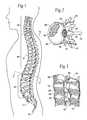
- FIG. 1is a lateral view of a human spinal column
- FIG. 2is a representative coronal view, with portions broken away and in section, of a human vertebral body, taken generally along line 2 — 2 in FIG. 1;
- FIG. 3is a lateral view, with portions broken away and in section, of several vertebral bodies, which are part of the spinal column shown in FIG. 1;
- FIG. 4is a plan view of a tool which carries at its distal end an expandable structure, which, in use, compresses cancellous bone, the structure being shown in a collapsed condition;
- FIG. 5is enlarged side view of the expandable structure carried by the tool shown in FIG. 4;
- FIG. 6is a coronal view of the vertebral body shown in FIG. 2, with a single tool shown in FIGS. 4 and 5 deployed through a lateral access in a collapsed condition;
- FIG. 7is a coronal view of the vertebral body and tool shown in FIG. 6, with the tool in an expanded condition to compress cancellous bone and form a cavity;
- FIG. 8is a coronal view of the vertebral body shown in FIGS. 6 and 7, with the tool removed after formation of the cavity;
- FIG. 9Ais a coronal view of the vertebral body shown in FIGS. 8, with the cavity filled with a material that strengthens the vertebral body;
- FIG. 9Bdepicts an alternate method of filling a cavity within a vertebral body
- FIG. 9Cdepicts the vertebral body of FIG. 9B, wherein the cavity is approximately half-filled with material
- FIG. 9Ddepicts the vertebral body of FIG. 9B, wherein the cavity is substantially filled with material
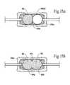
- FIG. 10is a coronal view of the vertebral body shown in FIG. 2, with two tools shown in FIGS. 4 and 5 deployed through bilateral accesses and in an expanded condition to compress cancellous bone and form adjoining, generally symmetric cavities;
- FIG. 11is a coronal view of the vertebral body shown in FIG. 10, with the tools removed after formation of the generally symmetric cavities and the cavities filled with a material that strengthens the vertebral body;
- FIG. 12is a coronal view of the vertebral body shown in FIG. 10, with the tools removed after formation of generally asymmetric cavities;
- FIG. 13is a anterior sectional view of three adjacent vertebral bodies, with six tools shown in FIGS. 4 and 5 deployed in collapsed conditions through two lateral accesses in each vertebral body;
- FIGS. 14A to 14 Dare schematic anterior views of one of the vertebral bodies shown in FIG. 13, showing the alternating, step wise application of pressure to the expandable structures to compress cancellous bone and form adjacent cavities;
- FIGS. 15A and 15Bare schematic anterior views of one of the vertebral bodies shown in FIGS. 14A to 14 D, depicting the alternating sequence of filling the adjacent cavities with a material to strength the vertebral body;
- FIGS. 16A to 16 Iare coronal views of a vertebral body as shown in FIGS. 14A to 14 D and 15 A and 15 B, showing tools deployed to create a lateral access to compress cancellous bone in a vertebral body to form an interior cavity, which is filled with a material to strengthen the vertebral body;
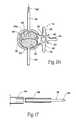
- FIG. 17is an exploded side section view of a reduced diameter obturator instrument with associated centering sleeve, which can be deployed to create access in a vertebral body, particularly through a pedicle;
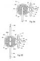
- FIG. 18Ais a side section view of a drill bit instrument that can be deployed to create access to a vertebral body, the drill bit instrument having a flexible shaft and deployed through a cannula instrument having a deflected end;
- FIG. 18Bis a side view of a drill bit instrument that can be deployed to create access to a vertebral body, the drill bit instrument having a flexible shaft and deployed over a guide wire having a deflected end;
- FIG. 18Cis a side view of a drill bit instrument that can be deployed to create access to a vertebral body, the drill bit instrument having a flexible shaft and including steering wires to deflect its distal end;
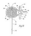
- FIG. 19is a coronal view of a vertebral body showing the deployment of a spinal needle tool in a manner that creates a breach in an anterior cortical wall of the vertebral body;
- FIG. 20Ais an enlarged side view of a drill bit instrument having a mechanical stop to prevent breach of an anterior cortical wall of the vertebral body;
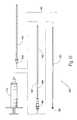
- FIG. 20Bis an enlarged side view of a cortical wall probe that can be deployed to gauge the interior dimensions of a vertebral body without breaching an anterior cortical wall of the vertebral body;
- FIG. 21is coronal view of a vertebral body with an expandable structure deployed and expanded, showing the introduction of a liquid to prevent formation of a vacuum upon the subsequent deflation and removal of the structure;
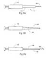
- FIG. 22Ais a side view of a tool to introduce material into a cavity formed in cancellous bone, with a nozzle having a stepped profile to reduce overall fluid resistance;
- FIG. 22Bis a side view of a tool to introduce material into a cavity formed in cancellous bone, with a nozzle having a tapered profile to reduce overall fluid resistance;
- FIG. 22Cis a side view of a tool to introduce material into a cavity formed in cancellous bone, with a nozzle having a reduced interior profile to reduce overall fluid resistance;
- FIG. 23are top views of kits which hold, prior to use, the various instruments and tools usable to create multiple access paths in a single vertebral body, to compact cancellous bone and form a cavity to be filled with a material, as generally shown in FIGS. 16A to 16 I;
- FIGS. 24A to 24 Care coronal views of a vertebral body, showing a small expandable body deployed through a needle to create a small cavity, and the injection of a filling material under pressure through the needle to fill and enlarge the cavity to strengthen the vertebral body;
- FIG. 25is an enlarged side section view of an expandable body carried at the end of a catheter tube, which further includes an integrated drill bit instrument;
- FIG. 26Ais a perspective view of one embodiment of a locking device for a cannula instrument
- FIG. 26Bis a perspective view of another embodiment of a locking device for a cannula instrument
- FIG. 27is a perspective view of a composite tool that includes a trocar and a cannula instrument
- FIG. 28is a perspective view of the composite instrument shown in FIG. 27, with the trocar separated from the cannula instrument;
- FIG. 29Ais a perspective view of a hand engaging the composite handle of the tool shown in FIG. 27;
- FIG. 29Bis a perspective view of a hand engaging the handle of the cannula instrument when separated from the trocar;
- FIG. 30is a top view showing deployment of the composite instrument shown in FIG. 27 in a vertebral body, by using the composite handle to apply an axial and/or torsional force;
- FIG. 31is a top view of the vertebral body, showing deployment of a drill bit through a cannula instrument, which forms a part of the composite tool shown in FIG. 27;
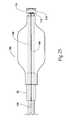
- FIG. 32depicts an exchange chamber for replacing and/or diluting the radiopaque medium within a structure with a partially-radiopaque or radiopaque-free medium;
- FIG. 33is an exploded perspective view of a cannula and material introducing device, which embodies features of the invention.
- the new systems and methodswill be described with regard to the treatment of vertebral bodies. It should be appreciated, however, the systems and methods so described are not limited in their application to vertebrae. The systems and methods are applicable to the treatment of diverse bone types, including, but not limited to, such bones as the radius, the humerus, the femur, the tibia, or the calcanus.
- the spinal column 10comprises a number of uniquely shaped bones, called the vertebrae 12 , a sacrum 14 , and a coccyx 16 (also called the tail bone).
- the number of vertebrae 12 that make up the spinal column 10depends upon the species of animal. In a human (which FIG. 1 shows), there are twenty-four vertebrae 12 , comprising seven cervical vertebrae 18 , twelve thoracic vertebrae 20 , and five lumbar vertebrae 22 .
- the spinal column 10When viewed from the side, as FIG. 1 shows, the spinal column 10 forms an S-shaped curve.
- the curveserves to support the head, which is heavy. In four-footed animals, the curve of the spine is simpler.
- each vertebra 12includes a vertebral body 26 , which extends on the anterior (i.e., front or chest) side of the vertebra 12 .
- the vertebral body 26is in the shape of an oval disk.
- the vertebral body 26includes an exterior formed from compact cortical bone 28 .
- the cortical bone 28encloses an interior volume 30 of reticulated cancellous, or spongy, bone 32 (also called medullary bone or trabecular bone).
- a “cushion,” called an intervertebral disk 34is located between the vertebral bodies 26 .
- the spinal ganglion 39pass through the foramen 36 .
- the spinal cord 38passes through the spinal canal 37 .
- the vertebral arch 40surrounds the spinal canal 37 .
- the pedicle 42 of the vertebral arch 40adjoins the vertebral body 26 .
- the spinous process 44extends from the posterior of the vertebral arch 40 , as do the left and right transverse processes 46 .
- Access to a vertebral bodycan be accomplished from many different directions, depending upon the targeted location within the vertebral body, the intervening anatomy, and the desired complexity of the procedure. For example, access can also be obtained through a pedicle 42 (transpedicular), outside of a pedicle (extrapedicular), along either side of the vertebral body (posterolateral), laterally or anteriorly.
- pedicle 42transpedicular
- extrapedicularoutside of a pedicle
- such approachescan be used with a closed, minimally invasive procedure or with an open procedure.
- FIG. 4shows a tool 48 for preventing or treating compression fracture or collapse of a vertebral body using an expandable body.
- the tool 48includes a catheter tube 50 having a proximal and a distal end, respectively 52 and 54 .
- the distal end 54carries a structure 56 having an expandable exterior wall 58 .
- FIG. 4shows the structure 56 with the wall 58 in a collapsed geometry.
- FIG. 5shows the structure 56 in an expanded geometry.
- FIG. 6shows the collapsed geometry permits insertion of the structure 56 into the interior volume 30 of a targeted vertebral body 26 , as FIG. 6 shows.
- the structure 56can be introduced into the interior volume 30 in various ways.
- FIG. 6shows the insertion of the structure 56 through a single lateral access, which extends through a lateral side of the vertebral body 12 .
- Lateral accessis indicated, for example, if a compression fracture has collapsed the vertebral body 26 below the plane of the pedicle 42 , or for other reasons based upon the preference of the physician. Lateral access can be performed either with a closed, mininimally invasive procedure or with an open procedure. Of course, depending upon the intervening anatomy, well known in the art, lateral access may not be the optimal access path for treatment of vertebrae at all levels of the spine.
- the catheter tube 50includes an interior lumen 80 (see FIG. 4 ).
- the lumen 80is coupled at the proximal end of the is catheter tube 50 to a pressurized source of fluid, e.g., saline.
- a syringe containing the fluidcan comprise the pressure source.
- the lumen 80conveys the fluid into the structure 56 under pressure. As a result, the wall 58 expands, as FIGS. 5 and 7 show.
- the fluidis preferably rendered radiopaque, to facilitate visualization as it enters the structure 56 .
- RenografinTMcan be used for this purpose.
- expansion of the structure 56can be monitored fluoroscopically or under CT visualization.
- the structure 56may be filled with sterile water, saline solution, or sugar solution, free of a radiopaque material.
- other types of visualizationcould be used, with the tool 48 carrying compatible reference markers.
- the structurecould incorporate a radiopaque material within the material of the structure, or the structure could be painted or “dusted” with a radiopaque material.
- Expansion of the wall 58enlarges the structure 56 , desirably compacting cancellous bone 32 within the interior volume 30 (see FIG. 7) and/or causing desired displacement of cortical bone.
- the compaction of cancellous bone 32forms a cavity 60 in the interior volume 30 of the vertebral body 26 (see FIG. 8 ).
- a filling material 62can be safely and easily introduced into the cavity 60 which the compacted cancellous bone 32 forms.
- expansion of the structure 56desirably forms a region of compacted cancellous bone which substantially surrounds the cavity 60 . This region desirably comprises a barrier which limits leakage of the filling material 62 outside the vertebral body 26 .
- the expansion of the structure 56desirably presses cancellous bone 32 into small fractures which may be present in cortical bone, thereby reducing the possibility of the filling material 62 exiting through the cortical wall.
- the expansion of the structure 56desirably flattens veins in the vertebral body that pass through the cortical wall (e.g., the basivertebral vein), resulting in less opportunity for filling material 62 to extravazate outside the vertebral body through the venous structure in the cortical wall.
- expansion of the structure 56will compress less dense and/or weaker regions of the cancellous bone, which desirably increases the average density and/or overall strength of the remaining cancellous bone.
- the compaction of cancellous bone by the structure 56can also exert interior force upon cortical bone.
- the structure 56can directly contact the cortical bone, such that expansion and/or manipulation of the structure will cause displacement of the cortical bone. Expansion of the structure 56 within the vertebral body 26 thereby makes it possible to elevate or push broken and compressed bone back to or near its original prefracture position.
- the structure 56is preferably left inflated within the vertebral body 26 for an appropriate waiting period, for example, three to five minutes, to allow some coagulation inside the vertebral body 26 to occur. After the appropriate waiting period, the physician collapses and removes the structure 56 . As FIG. 8 shows, upon removal of the structure 56 , the formed cavity 60 remains in the interior volume 30 .
- the filling material 62(which FIG. 9A shows after its introduction into the cavity 60 ) can comprise a material that resists torsional, tensile, shear and/or compressive forces within the cavity 60 , thereby providing renewed interior structural support for the cortical bone 28 .
- the material 62can comprise a flowable material, such as bone cement, allograft tissue, autograft tissue, or hydroxyapatite, synthetic bone substitute, which is introduced into the cavity 60 and which, in time, sets to a generally hardened condition.
- the material 62can also comprise a compression-resistant material, such as rubber, polyurethane, cyanoacrylate, or silicone rubber, which is inserted into the cavity 60 .
- the material 62can also comprise a semi-solid slurry material (e.g., a bone slurry in a saline base), which is either contained within a porous fabric structure located in the cavity 60 or injected directly into the cavity 60 , to resist compressive forces within the cavity 60 .
- the material 62could comprise stents, reinforcing bar (Re-Bar) or other types of internal support structures, which desirably resist compressive, tensile, torsional and/or shear forces acting on the bone and/or filler material.
- the filling material 62may also comprise a medication, or a combination of medication and a compression-resistant material, as described above.
- the filling material 62can comprise a bone filling material which does not withstand compressive, tensile, torsional and/or shear forces within the cavity.
- the filling material 62need not be able to immediately bear load.
- the filling material 62could provide a scaffold for bone growth, or could comprise a material which facilitates or accelerates bone growth, allowing the bone to heal over a period of time.
- the filling materialcould comprise a resorbable or partially-resorbable source of organic or inorganic material for treatment of various bone or non-bone-related disorders including, but not limited to, osteoporosis, cancer, degenerative disk disease, heart disease, acquired immune deficiency syndrome (AIDS) or diabetes.
- the cavity and/or filler materialcould comprise a source of material for treatment of disorders located outside the treated bone.
- the expandable structure 56can be left in the cavity 60 .
- flowable filling material 62is conveyed into the structure 56 , which serves to contain the material 62 .
- the structure 56filled with the material 62 , serves to provide the renewed interior structural support function for the cortical bone 28 .
- the structure 56can be made from an inert, durable, non-degradable plastic material, e.g., polyethylene and other polymers.
- the structure 56can be made from an inert, bio-absorbable material, which degrades over time for absorption or removal by the body.
- the filling material 62itself can serve as the expansion medium for the structure 56 , to compact cancellous bone and form the cavity 60 , to thereby perform both compaction and interior support functions.
- the structure 56can be first expanded with another medium to compact cancellous bone and form the cavity 60 , and the filling material 62 can be subsequently introduced after the expansion medium is removed from structure 56 to provide the interior support function.
- the filling materialcould comprise a two-part material including, but not limited to, settable polymers or calcium alginate. If desired, one part of the filling material could be utilized as the expansion medium, and the second part added after the desired cavity size is achieved.
- the structure 56can also be made from a permeable, semi-permeable, or porous material, which allows the transfer of medication contained in the filling material 62 into contact with cancellous bone through the wall of the structure 56 .
- the materialcan comprise a membrane that allows osmotic and/or particulate transfer through the material, or the material can comprise a material that allows the medication to absorb into and/or diffuse through the material.
- medicationcan be transported through a porous wall material by creating a pressure differential across the wall of the structure 56 .
- fluids, cells and/or other materials from the patient's bodycan pass and/or be drawn through the material into the structure for various purposes including, but not limited to, fluid/cellular analysis, bony ingrowth, bone marrow harvesting, and/or gene therapy (including gene replacement therapy).
- an enlarged cavity 64occupying substantially all of the interior volume, can be created by the deployment of multiple expandable structures 56 A and 56 B through two lateral separate accesses PLA 1 and PLA 2 , made in opposite lateral sides of a vertebral body 26 .
- the expandable structures 56 A and 56 Bare carried by separate tools 48 A and 48 B at the distal ends of catheter tubes 50 A and 50 B, which are separate and not joined together.
- Expansion of the multiple expandable structures 56 A and 56 Bforms two cavity portions 64 A and 64 B (shown in FIG. 11 ).
- the cavity portions 64 A and 64 Bare transversely spaced within the cancellous bone 32 .
- the transversely spaced cavity portions 64 A and 64 Bpreferably adjoin to form the single combined cavity 64 (shown in FIG. 11 ), into which a filling material is injected.
- the transversely spaced cavity portions 64 A and 64 Bcan remain separated by a region of cancellous bone.
- the filling materialis still injected into each cavity portion 64 A and 64 B.
- FIG. 10shows the structures 56 A and 56 B to possess generally the same volume and geometry, when substantially expanded. This arrangement provides a symmetric arrangement for compacting cancellous bone 32 . A generally symmetric, enlarged cavity 64 (shown in FIG. 11) results.
- the structures 56 A and 56 Bmay possess different volumes and/or geometries when substantially expanded, thereby presenting an asymmetric arrangement for compacting cancellous bone 32 .
- a generally asymmetric cavity 66results.
- the selection of size and shape of the structures 56 A and 56 B, whether symmetric or asymmetric,depends upon the size and shape of the targeted cortical bone 28 and adjacent internal anatomic structures, or by the size and shape of the cavity 64 or 66 desired to be formed in the cancellous bone 32 . It can be appreciated that the deployment of multiple expandable structures 56 A and 56 B makes it possible to form cavities 64 or 66 having diverse and complex geometries within bones of all types.
- compression fracture or collapse of one vertebral bodycan occur in combination with compression fracture or collapse of an adjacent vertebral body or bodies.
- the failure of one vertebral bodymay alter loading of adjacent vertebral bodies, or can cause unequal loading of adjacent vertebral bodies, resulting in failure of one of more of the adjacent bodies as well.
- these adjacent vertebral bodiesare susceptible to fracture and/or collapse.
- the treatment of a compression fracture of a single vertebral bodymay alter the loading of the adjacent vertebral bodies, possibly resulting in failure of one of more of the adjacent bodies. The treatment of two or more vertebral bodies during a single procedure may therefore be indicated.
- FIG. 13shows a procedure treating three adjacent vertebral bodies 26 A, 26 B, and 26 C, each with bilateral accesses.
- the multiple bilateral procedureentails the deployment of six expandable structures 56 ( 1 ) to 56 ( 6 ), two in each vertebral body 26 A, 26 B, and 26 C.
- expandable structures 56 ( 1 ) and 56 ( 2 )are bilaterally deployed in vertebral body 26 A; expandable structures 56 ( 3 ) and 56 ( 4 ) is are bilaterally deployed in vertebral body 26 B; and expandable structures 56 ( 5 ) and 56 ( 6 ) are bilaterally deployed in vertebral body 26 C.
- the volume of a given cavity 64 formed in cancellous bone using multiple expandable structurescan be optimized by alternating the expansion of the multiple expandable structures deployed. For example, in the illustrated embodiment, in each vertebral body, one of the expandable structures 56 ( 1 ) is first expanded, followed by the expansion of the other expandable body 56 ( 2 ).
- cancellous boneWhen pressure is first applied to expand a given structure 56 ( 1 ) to 56 ( 6 ), cancellous bone will begin to compact and/or cortical bone will begin to displace. A period of time follows in which the pressure within the structure 56 ( 1 ) to 56 ( 6 ) typically decays, as the cancellous bone relaxes, further compacts and/or cortical bone is further displaced. Pressure decay in one structure also typically occurs as the other expandable structure within the vertebral body is expanded. When pressure is again restored to the structure 56 ( 1 ) to 56 ( 6 ), further cancellous bone compaction and/or cortical bone displacement generally results. A further decay in pressure in the structure 56 ( 1 ) to 56 ( 6 ) will then typically follow. A decay of pressure will generally follow the application of pressure, until the cancellous bone is compacted a desired amount and/or cortical bone is displaced to a desired position.
- FIGS. 14A to 14 Dmore particularly demonstrate this step wise sequence of applying pressure to a given pair of expandable structures, e.g., 56 ( 1 ) and 56 ( 2 ), when deployed bilaterally in a vertebral body 26 A.
- step wise application of pressurecan also be used when a single expandable body is deployed, or when one or more expandable structures are deployed in other than in a lateral fashion, e.g., using a transpedicular, extrapedicular, or anterior access.
- expandable structures incorporating non-compliant materialscould be used in similar manners to accomplish various objectives of the present invention.
- the expandable structurescomprise non-compliant materials
- such structurescould be expanded within the cancellous bone in the previously described manner to compress cancellous bone, create a cavity and/or displace cortical bone.
- the described application of additional pressure to the structurescould cause a similar cycle of volumetric growth and pressure decay.
- the introduction of additional pressurewould typically result in little volumetric expansion of the structures.
- the expandable structures 56 ( 1 ) and 56 ( 2 )have been individually deployed in separate lateral accesses in vertebral body 26 A.
- the expandable structures 56 ( 3 )/ 56 ( 4 ) and 56 ( 5 )/ 56 ( 6 )are likewise individually deployed in separate lateral accesses in vertebral bodies 26 B and 26 C, respectively, as FIG. 13 shows. Representative instruments for achieving these lateral accesses will be described later.
- FIG. 14Ashows the initial application of pressure to structure 56 ( 1 ).
- the physiciancan deploy expandable structures in a single vertebral body, expand those structures as described herein, and then deploy and expand expandable structures within another vertebral body.
- the physiciancan deploy the expandable structures in a single vertebral body, expand those structures as described herein, fill the cavities within that vertebral body, and then deploy and expand expandable structures within another vertebral body.
- the pressure in the structures 56 ( 1 ), 56 ( 3 ), and 56 ( 5 )will, over time decay, as the cancellous bone in each vertebral body 26 A, 26 B, and 26 C relaxes, further compresses and/or cortical bone displaces in the presence of the expanded structure 56 ( 1 ), 56 ( 3 ), and 56 ( 5 ), respectively.
- the physicianproceeds to successively apply pressure to the other expandable structures 56 ( 2 ), 56 ( 4 ), and 56 ( 6 ) in the same vertebral bodies 26 A, 26 B, and 26 C, respectively.
- FIG. 14Bshows the application of pressure to structure 56 ( 2 ), as the pressure in structure 56 ( 1 ) decays.
- each structure 56 ( 2 ), 56 ( 4 ), and 56 ( 6 )will likewise decay over time, as the cancellous bone in each vertebral body 26 A, 26 B, and 26 C is compressed in the presence of the expanded structure 56 ( 2 ), 56 ( 4 ), and 56 ( 6 ), respectively.
- the physicianproceeds to successively apply additional pressure to the other expandable structures 56 ( 1 ), 56 ( 3 ), and 56 ( 5 ) in the vertebral bodies 26 A, 26 B, and 26 C, respectively.
- FIG. 14Cshows the introduction of additional pressure to structure 56 ( 1 ) as pressure decays in structure 56 ( 2 ).
- the desired cavity volumeis achieved when cancellous bone is uniformly, tightly compacted against surrounding cortical bone.
- desired cavity volumeis achieved when a significant pressure decay no longer occurs after the introduction of additional pressure, such as where substantially all of the cancellous bone has been compressed and/or the cortical bone does not displace further.
- compaction of cancellous bonemay be non uniform due to varying factors, including local variations in bone density.
- desired displacement of cortical bonecan be accomplished in a similar manner, either alone or in combination with compaction of cancellous bone.
- each cavity 64Once the desired volume for each cavity 64 and/or desired displacement of cortical bone in each vertebral body 26 A, 26 B, and 26 C is reached, the physician begins the task of conveying a selected filling material 62 into each formed cavity 64 . It should be appreciated that the cavities 64 can be filled with filling material 62 essentially in any order, and it is not necessary that all expandable structures be expanded to form all the cavities 64 before the filling material is conveyed into a given cavity.
- the filling materialis conveyed in alternating steps into the cavity portions 64 A and 64 B of each vertebral body 26 A, 26 B, and 26 C.
- the cavity volumes 64 A formed by the expandable structures 56 ( 1 ), 56 ( 3 ), and 56 ( 5 )are filled in succession before the cavity volumes 64 B formed by the expandable structures 56 ( 2 ), 56 ( 4 ), and 56 ( 6 ) are filled in succession.
- FIGS. 15A and 15Bshow this embodiment of a filling sequence for the vertebral body 26 A.
- the vertebral bodies 26 B and 26 Care filled in like manner.
- the expandable structure 56 ( 1 )is deflated and removed.
- the filling material 62is then conveyed into the corresponding cavity portion 64 A.
- the expandable structure 56 ( 3 )is deflated and removed, and the filling material 62 conveyed into the corresponding cavity portion 64 A.
- the expandable structure 56 ( 5 )is deflated and removed, and the filling material 62 conveyed into the corresponding cavity portion 64 A.
- the expandable structures 56 ( 2 ), 56 ( 4 ), and 56 ( 6 )are left inflated within the respective vertebral bodies 26 A, 26 B, and 26 C during this portion of the filling process.
- the physicianwaits for the filling material 62 conveyed into the vertebral bodies 26 A, 26 B, and 26 C to harden. Then, as FIG. 15B shows for the vertebral body 26 A, the expandable structure 56 ( 2 ) is deflated and removed. The filling material 62 conveyed into the corresponding cavity portion 64 B. Next, in the vertebral body 26 B, the expandable structure 56 ( 4 ) is deflated and removed, and the filling material 62 conveyed into the corresponding cavity portion 64 B. Last, in the vertebral body 26 C, the expandable structure 56 ( 6 ) is deflated and removed, and the filling material 62 conveyed into the corresponding cavity portion 64 B. The above sequence allows a single batch of the filling material 62 to be mixed and expeditiously dispensed to fill multiple cavities 64 .
- the filling materialis conveyed in alternating steps into the cavity portions of each respective vertebral body prior to filling the next vertebral body.
- the expandable structure 56 ( 1 )is removed from the vertebral body, and filling material is conveyed into the corresponding cavity portion 64 A.
- the expandable structure 56 ( 2 )is then removed from the vertebral body, and filling material is conveyed into the corresponding cavity portion 64 B.
- the filling materialcan be allowed to harden to some degree before the expandable structure 56 ( 2 ) is removed from the vertebral body. The process is then repeated for each remaining vertebral body to be treated.
- the vertebral bodyis desirably substantially supported by the filling material and/or an expandable structure during the filling process, which reduces and/or eliminates the opportunity for the cavity to collapse and/or cortical bone to displace in an undesired direction during the filling operation.
- a patientlies on an operating table.
- the patientcan lie face down on the table, or on either side, or at an oblique angle, depending upon the physician's preference.
- the physicianFor each access (see FIG. 16 A), the physician introduces a spinal needle assembly 70 into soft tissue ST in the patient's back. Under radiologic or CT monitoring, the physician advances the spinal needle assembly 70 through soft tissue down to and into the targeted vertebral body 26 .
- the physiciancan also employ stereotactic instrumentation to guide advancement of the spinal needle assembly 70 and subsequent tools during the procedure.
- the reference probe for stereotactic guidancecan be inserted through soft tissue and implanted on the surface of the targeted vertebral body.
- the entire procedurecan also be monitored using tools and tags made of non-ferrous materials, e.g., plastic or fiber composites, such as those disclosed in U.S. Pat. Nos. 5,782,764 and 5,744,958, which are each incorporated herein by reference, which would be suitable for use in a computer enhanced, whole-room MRI environment.
- the physicianwill typically administer a local anesthetic, for example, lidocaine, through the assembly 70 .
- a local anestheticfor example, lidocaine
- the physicianmay prefer other forms of anesthesia.
- the physiciandirects the spinal needle assembly 70 to penetrate the cortical bone 28 and the cancellous bone 32 through the side of the vertebral body 26 .
- the depth of penetrationis about 60% to 95% of the vertebral body 26 .
- the physicianholds the stylus 72 and withdraws the stylet 74 of the spinal needle assembly 70 . As FIG. 16B shows, the physician then slides a guide pin instrument 76 through the stylus 72 and into the cancellous bone 32 . The physician now removes the stylus 72 , leaving the guide pin instrument 76 deployed within the cancellous bone 32 .
- the physiciannext slides an obturator instrument 78 over the guide pin instrument 76 , distal end first, as FIG. 16C shows.
- the physiciancan couple the obturator instrument 78 to a handle 80 , which facilitates manipulation of the instrument 78 .
- the physicianmakes a small incision in the patient's back.
- the physiciantwists the handle 80 while applying longitudinal force to the handle 80 .
- the obturator instrument 78rotates and penetrates soft tissue through the incision.
- the physicianmay also gently tap the handle 80 , or otherwise apply appropriate additional longitudinal force to the handle 80 , to advance the obturator instrument 78 through the soft tissue along the guide pin instrument 76 down to the cortical bone entry site.
- the physiciancan also tap the handle 80 with an appropriate striking tool to advance the obturator instrument 78 into a side of the vertebral body 26 to secure its position.
- the obturator instrument 78 shown in FIG. 16Chas an outside diameter that is generally well suited for establishing a lateral access. However, if access is desired through the more narrow region of the vertebral body 26 , e.g., a pedicle 42 (called transpedicular access), the outside diameter of the obturator instrument 78 can be reduced (as FIG. 17 shows). The reduced diameter of the obturator instrument 78 in FIG. 17 mediates against damage or breakage of the pedicle 42 .
- the reduced diameter obturator instrument 78 shown in FIG. 17includes a pointed tip 82 to help secure its position against cortical bone 28 . It should be understood that the disclosed methods and devices are well suited for use in conjunction with other approach paths, such as pedicular, extra-pedicular, posterolateral and anterior approaches, with varying results.
- the physicianthen proceeds to slide the handle 80 off the obturator instrument 78 and to slide a cannula instrument 84 over the guide pin instrument 76 and, further, over the obturator instrument 78 .
- the physiciancan also couple the handle 80 to the cannula instrument 84 , to apply appropriate twisting and longitudinal forces to rotate and advance the cannula instrument 84 through soft tissue ST over the obturator instrument 78 .
- the physiciancan appropriately tap the handle 80 with a striking tool to advance the end surface into the side of the vertebral body 26 to secure its position.
- the cannula instrument 84can carry a removable inner sleeve 86 (as FIG. 17 also shows) to center the cannula instrument 84 about the reduced diameter obturator instrument 78 during passage of the cannula instrument 84 to the treatment site.
- the physiciannow withdraws the obturator instrument 78 , sliding it off the guide pin instrument 76 , leaving the guide pin instrument 76 and the cannula instrument 84 in place.
- the physiciancan remove the inner centering sleeve 86 .
- the physicianslides a drill bit instrument 88 over the guide pin instrument 76 , distal end first, through the cannula instrument 84 , until contact between the machined or cutting edge 90 of the drill bit instrument 88 and cortical bone 28 occurs.
- the physicianthen couples the drill bit instrument 88 to the handle 80
- the physicianapplies appropriate twisting and longitudinal forces to the handle 80 , to rotate and advance the machined edge 90 of the drill bit instrument 88 to open a lateral passage PLA through the cortical bone 28 and into the cancellous bone 32 .
- the drilled passage PLApreferably extends no more than 95% across the vertebral body 26 .
- the drill bit instrument 88can include a flexible shaft portion 92 to aid in its manipulation.
- the flexible shaft portion 92allows the cutting edge 90 of the instrument 88 to flex relative to the axis of the instrument.
- the cannula instrument 84can, if desired, include a deflector element 94 on its distal extremity, to flex the flexible shaft portion 92 and guide the cutting edge 90 along a desired drill axis.
- the drill bit instrument 88is made of a flexible plastic material, e.g., polyurethane, or a flexible metal material encapsulated in or surrounding a plastic material, to possess sufficient torsional rigidity to transmit rotating cutting force to bone.
- the drill bit instrument 88can include an interior lumen 180 to accommodate passage of a guide wire 182 .
- the flexible shaft portion 92conforms to the path presented by the guide wire 182 .
- the guide wire 182can be pre-bent, to alter the path of the cutting edge 90 after it enters the vertebral body.
- the guide wirecan be made of memory wire, shape memory alloys (including nickel-titanium, copper or iron based alloys, to name a few), or comprise a self-steering guiding catheter.
- the drill bit instrument 88itself can carry interior steering wires 184 .
- the steering wires 184are operated by the physician using an external actuator 186 , to deflect the flexible shaft portion 92 , and with it the cutting edge, without aid of a guide wire and/or cannula instrument 84 .
- the physicianremoves the drill bit instrument 88 and the guide pin instrument 76 , leaving only the cannula instrument 84 in place, as FIG. 16E shows.
- the passage PLA made by the drill bit instrument 88remains. Subcutaneous lateral access to the cancellous bone 32 has been accomplished.
- the physicianrepeats the above described sequence of steps, as necessary, to form each access desired. In FIG. 13, six accesses are made.
- FIGS. 27 and 28show a composite instrument 310 that can be used for this purpose.
- the composite instrument 310includes a trocar instrument 320 and a cannula instrument 340 .
- the composite instrument 310also includes a composite handle 312 comprising a first handle 322 and a second handle 342 .
- the composite handle 312aids a physician in manipulating the composite instrument 310 .
- FIGS. 29A and 29Bshow, a physician can also desirably use the first handle 322 to independently manipulate the trocar instrument 320 or the second handle 342 to independently manipulate the cannula instrument 340 during use.
- the trocar instrument 320comprises a trocar 330 having a distal end that is tapered to present a penetrating surface 334 .
- the penetrating surface 334is intended to penetrate soft tissue and/or bone in response to pushing and/or twisting forces applied by the physician at the first handle 322 , or the composite handle 312 .
- the cannula instrument 340performs the function of the cannula instrument 84 previously described, but also includes the handle 342 , which mates with the handle 322 to form the composite handle 312 .
- the cannula instrument 84is desirably somewhat larger in diameter than and not as long as the trocar 330 .
- the cannula instrument 84includes an interior lumen 344 that is sized to accept the trocar 330 . The size of the interior lumen 344 desirably allows the cannula instrument 84 to slide and/or rotate relative to the trocar 330 , and vice versa.
- the distal end 354 of the cannula instrument 84presents an end surface 360 that desirably presents a low-profile surface, which can penetrate soft tissue surrounding the trocar 330 in response to pushing and/or twisting forces applied at the composite handle 312 or the second handle 342 .
- the physiciandirects the composite instrument 310 such that the trocar 330 and the cannula instrument 84 penetrate the cortical bone and the cancellous bone of the targeted vertebra.
- the physiciancan twist the composite handle 312 while applying longitudinal force to the handle 312 .
- the penetrating end surface 334 of the trocar 330 , and the end surface of the cannula instrument 84rotate and penetrate soft tissue and/or bone.
- a physiciancan continue penetration by gently striking a striking plate 314 on the composite handle 312 with a blunt instrument such as a surgical hammer (not shown), or otherwise applying appropriate additional longitudinal force to the composite handle 312 , to advance the distal end 334 of the trocar 330 and the end surface of the cannula instrument 84 .
- a blunt instrumentsuch as a surgical hammer (not shown)
- the physiciancan utilize a spinal needle assembly 70 , as already described, to initially access the vertebral body.
- the composite instrument 310is later guided through soft tissue and into the targeted vertebra body along the stylet 74 , which (in this arrangement) passes through an interior lumen in the trocar 330 (not shown)
- the physiciancan withdraw the stylet 74 , thereby arriving at the step in the procedure shown in FIG. 30 .
- the physicianmay continue advancing the composite instrument 310 through the cancellous bone of the vertebral body to form the passage through the cancellous bone, as already described.
- the trocar 330may then be withdrawn from the cannula instrument 84 .
- the cannula instrument 84remains to provide access to the passage formed in the interior of the vertebral body, in the manner previously described.
- the physicianmay choose to withdraw the trocar 330 from the cannula 50 and form the passage in the cancellous bone using a drill bit instrument 88 , as FIG. 31 shows.
- the physicianremoves the trocar 330 and, in its place, advances the drill bit instrument 88 through the cannula instrument 84 , as FIG. 31 shows.
- the physiciantypically advances a stylet 74 of the spinal needle assembly 70 and also the cutting edge of the drill bit instrument 88 a significant distance into the cancellous bone 32 , as FIGS. 16B and 16D show, toward cortical bone 28 on the anterior wall of the vertebral body 26 .
- the density of the cancellous bone 32desirably offers resistance to the passage of these instruments, to thereby provide tactile feed back to the physician, which aids in guiding their deployment. Still, the density of cancellous bone 32 is not uniform and can change abruptly.
- the stylet 74 or the cutting edge 90can slide into and poke through cortical bone 28 in the anterior wall of the vertebral body 26 . This can create a hole or breach B in the anterior cortical wall 28 of the vertebral body 26 , as FIG. 19 shows.
- the drill bit instrument 88may include a mechanical stop 96 .
- the mechanical stop 96abuts against the proximal end of the cannula instrument 84 . The abutment stops further advancement of the drill bit instrument 88 into the interior of the vertebral body 26 .
- the location of the mechanical stop 96may be adjustable, to provide variable lengths of advancement, depending upon the size of the vertebral body 26 or other bone volume targeted for treatment.
- the drill bit instrument 88may include markings 98 located along its length at increments from its terminus. The markings 98 register with the exposed proximal edge of the cannula instrument 84 (see FIG. 20 A), to allow the physician to remotely gauge the position of the instrument in the vertebral body 26 .
- the cortical wall probe 140comprises a generally rigid stylet body 142 having a blunt distal tip 144 , which desirably cannot easily pierce the anterior cortical wall of the vertebral body.
- the blunt distal tip 144comprises a rounded ball shape.
- the cortical wall probe 140can be deployed through the formed access opening before any significant penetration of cancellous bone occurs. For example, after the access opening is formed using the spinal needle assembly 70 , but before the stylus 72 and stylet 74 are advanced a significant distance into cancellous bone, the stylet 74 can be withdrawn and, instead, the cortical wall probe 140 advanced through the stylus 72 . The physician advances the cortical wall probe 140 through cancellous bone, until the physician tactilely senses contact between the blunt distal tip 144 and the anterior. cortical wall.
- the probe 140is radiopaque, so that its advancement through cancellous bone and its contact with the anterior cortical wall within the vertebral body can be visualized, e.g., either by x-ray or real time fluoroscopy or MRI.
- the physiciancan gauge the distance between the access opening into the vertebral body and the anterior cortical wall, in a manner that avoids penetration of the anterior cortical wall.
- the cortical wall probe 140can carry length markings 146 on its proximal region, which, when contact with the anterior cortical wall occurs and/or is imminent, indicate the distance a subsequent instrument can be advanced down the stylus 72 (or cannula instrument 84 ) before contacting the anterior cortical wall.
- the information obtained from the cortical wall probe 140can also be used to set the mechanical stop 96 (previously described), to physically prevent advancement of the trocar 330 or drill bit instrument 88 before contact with the anterior cortical wall occurs.
- the physiciancan alternatively utilize the cortical wall probe 140 to safely and easily determine the existence and/or extent of a wall breach. Because the distal tip 144 of the probe is blunt, the tip 144 desirably will not easily pass through an intact anterior cortical wall, which allows the physician to “tap” the tool along the inner surface of the anterior cortical wall while searching for breaches. Where a wall breach has occurred, and the tool could pass through the breach, the blunt tip 144 of the tool desirably will not pierce or damage soft tissues, such as the aorta or major veins, located forward of the cortical wall. If desired, the blunt tip 144 can alternatively be formed of a soft, deformable material such as rubber or plastic.
- a suitable materialmay be placed into the breach B to plug it.
- a demineralized bone matrix materialsuch as GRAFTONTM material, may be used.
- the materialcan be placed, e.g., on the distal end of the obturator instrument 78 or trocar 330 .
- the instrument 78is deployed carrying the plugging material to the exterior side wall where the breach B occurs.
- the instrument 78deposits the plugging material in the breach B, to thereby close it from the outside of the vertebral body 26 .
- the physiciancan take steps to counteract undetermined cortical wall breaches, either as may possibly preexist before cavity formation or which may possibly exist after cavity formation. Even if a breach is not known to exist, the physician can nevertheless elect to insert a suitable plug material (e.g., GRAFTONTM bone matrix material, or CollagraftTM sheet material, or a mesh-type material) into the vertebral body, either before or after the structure 56 is expanded.
- a suitable plug materiale.g., GRAFTONTM bone matrix material, or CollagraftTM sheet material, or a mesh-type material
- the presence of a plug materialguards against the possibility of leaks, whether they exist or not.
- the presence of the plug material in the vertebral bodycan serve to make the distribution of the expansion force of the structure 56 more uniform.
- the presence of the plug material within the vertebral body as the structure 56 expandscan also protect against protrusion of the expanding structure 56 through any preexisting breach in the cortical wall as well as any breaches created during expansion of the structure 56 , or can otherwise protect weakened cortical walls during expansion of the structure 56 .
- a cannula locking device 190can be used to aid in stabilizing the cannula instrument 84 while accessing a vertebral body.
- the locking device 190can be variously constructed.
- the locking device 190includes a generally planar base 192 .
- the base 192rests upon a skin surface surrounding the targeted incision site.
- the base 192can incorporate an adhesive (not shown) to secure the base to the patient's skin or to other material located at or near the surgical site.
- the instrument grip 194is supported on the base 192 .
- the instrument grip 194includes a channel 218 which slidingly receives the cannula instrument 84 , which, in this embodiment, is intended to be placed into the grip 194 distal end first.
- a ring 220threaded to the grip 194 , can be provided to tighten the channel 218 about the cannula instrument 84 , to thereby prevent axial movement of the cannula instrument 84 within the channel 218 .
- the grip 194also includes a tenon 196 , which fits within a mortise 198 on the base 192 .
- the mortise 198 and tenon 196together form a joint 200 .
- the grip 194pivots 360-degrees in transverse and/or orbital paths within the joint 200 .
- the mortise 198is bounded by a collet 210 , about which a retaining ring 202 is threadably engaged. Twisting the ring 202 in one direction (e.g., clockwise) closes the collet 210 about the tenon 196 , locking the position of the grip 194 relative to the base 192 . Twisting the ring 202 in an opposite direction opens the collet 210 about the tenon 196 , freeing the grip 194 for pivotal movement relative to the base 192 .
- the physicianmanipulates the cannula instrument 84 held in the grip 194 into a desired axial and angular orientation.
- the physicianthereafter locks the grip 194 (tightening the rings 202 and 220 ) to hold the cannula instrument 84 in the desired axial and angular orientation.
- the physiciancan manipulate and lock the cannula instrument 84 in any desired order, either before or after passage of the instrument 84 through the skin, and/or before or after passage of the instrument 84 through cortical bone, or combinations thereof.
- Markings 204 on the grip 194 and base 192allow the physician to gauge movement of the grip 194 relative to the base 192 or another reference point.
- the locking device 190is preferably made from a material that is not highly radiopaque, e.g., polyurethane or polycarbonate. The device 190 will therefore not obstruct fluoroscopic or x-ray visualization of the cannula instrument 84 during use.
- the device 190When locked, the device 190 prevents unintended movement of the cannula instrument 84 along the skin surface. The likelihood that the cannula instrument 84 will be bent or its position inadvertently shifted during use is thereby mitigated.
- the device 190also allows the physician to remove his/her hands from the instrument 84 , e.g., to allow clear fluoroscopy or x-ray visualization.
- the device 190obviates the need for other types of clamps that are radiopaque or are otherwise not well suited to the task.
- the retaining ring 202can be loosened to a point that opens the collet 210 enough to free the grip 194 from the base 192 .
- the grip 194comprises members 206 and 208 that can be split apart when separated from the confines of the collet 210 .
- the cannula instrument 84can be captured between the spit-apart members 206 and 208 as they are fitted back together, obviating the need to load the cannula instrument 84 distal end first in the grip 194 .
- the tenon 196When fitted together, the tenon 196 can be returned to the mortise 198 .
- the retaining ring 202can be tightened sufficiently to close the collet 210 about the tenon 196 , forming the joint 200 . Further tightening of the retaining ring 202 about the mortise 198 closes the joint 200 (as before described), locking the grip 194 a desired orientation relative to the base 192 . Subsequent loosening of the retaining ring 202 permits separation of the grip 194 from the base 192 , so that the members 206 and 208 can be split apart to free the cannula instrument 84 .
- the grip 194can contact the cannula directly, such that the cannula is substantially “locked ” in position when the grip 194 is compressed against the cannula.
- an O-ring(not shown) can be located within the grip 194 , such that compression of the grip causes the O-ring to push against the cannula, desirably substantially “locking” the cannula in position within the grip 194 .
- FIG. 16Fshows this deployment in vertebral body 26 A.
- the expandable structures 56 ( 1 ) to 56 ( 6 )are then expanded in the alternating, step wise fashion as already described.
- the compressionforms the interior cavity 64 in each vertebral body 26 A, 26 B, and 26 C.
- the expandable structure 56can carry at least one radiopaque marker 102 , to enable remote visualization of its position within the vertebral body 26 .
- the expandable structure 56carries a radiopaque marker 102 on both its distal and proximal end.
- the fluid used to cause expansion of the structure 56is preferably rendered radiopaque (e.g., using RenografinTM material).
- the visualization instrumente.g., a C-arm fluoroscope
- the presence of radiopaque expansion medium in a expanded structure 56 in the vertebral body 26can block effective visualization elsewhere in the vertebral body, e.g., where cavity formation using another structure 56 or where vertebroplasty or another form of treatment is intended to occur.
- Visualizationcan be facilitated under these circumstances by removal or dilution of the radiopaque medium within the structure 56 after the structure is expanded to create a cavity.
- an exchange chamber 400is provided, which is divided into two compartments 402 and 404 by a piston 414 that is movable by pressure upon a plunger 420 .
- Dual lumens 406 and 408communicate with the interior of the structure 56 .
- the lumen 406communicates with the source 422 of radiopaque medium 410 to convey the medium 410 into the structure 56 to cause expansion and cavity formation in the first instance.
- the lumen 406also communicates with the compartment 402 on one side of the piston 414 .
- the other compartment 404 of the chamber 400contains a replacement expansion medium 412 .
- the replacement medium 412is free of a radiopaque material or, if desired, can contain a partially-radiopaque material.
- the lumen 408communicates with this compartment 404 .
- an ion exchange material for the radiopaque material in the medium 410can be introduced into the radiopaque medium 410 contained within the structure 56 .
- the ion exchange materialselectively binds the radiopaque material, diluting the radiopaque qualities of the medium 410 .
- the radiopaque medium 410can be circulated through an ionic exchange chamber outside the structure 56 , or the ion exchange material can be introduced into the structure 56 through an interior lumen within the structure 56 itself.
- a material that causes precipitation of radiopaque materialcan be introduced into the radiopaque medium 410 within the structure 56 (e.g., through an interior lumen). The precipitation selectively causes the radiopaque material to settle downward within the structure 56 , out of the lateral visualization path, thereby diluting the radiopaque qualities of the medium 410 .
- the expandable structure 56can also include an interior tube 104 .
- the interior tube 104contains an interior lumen 106 that passes through the expandable structure 56 .
- the interior lumen 106can be used to convey a flowable material or liquid, e.g. saline or sterile water, to flush materials free of the distal region of the structure 56 , when in use.
- the interior lumen 106can also be used to aspirate liquid material from the interior of the vertebral body 26 as the procedure is performed.
- the interior lumen 106can also be used to introduce a thrombogenic material, e.g., a clotting agent, into contact with cancellous bone 32 during the procedure.
- the expandable structure 56itself can be also dipped into thrombin prior to its introduction into the vertebral body 26 to facilitate in situ coagulation.
- the interior lumen 106can also be sized to receive a stiffening member or stylet 108 (see FIG. 5 ).
- the stylet 108keeps the structure 56 in a desired distally straightened condition during its passage through the cannula instrument 84 . Once the structure 56 is located in the desired location within cancellous bone, the physician can remove the stylet 108 , and thereby open the interior lumen 106 for conveyance of liquids to and from cancellous bone, as just described.
- the stylet 108can also have a preformed memory, to normally bend its distal region.
- the memoryis overcome to straighten the stylet 108 when passed through the cannula instrument 84 .
- the preformed memorybends the stylet 108 .
- the bent stylet 108shifts the axis of the structure relative to the axis of the access path PLA.
- the prebent stylet 108positioned within the interior of the structure 56 , aids in altering the geometry of the structure 56 to achieve a desired orientation when deployed for use.
- the distal end of the stylet 108can be set to a prebent “parent shape,” and then subsequently bent to a substantially straight shape for introduction into the vertebral body.
- a shape memory alloysuch as nickel-titanium(Nitinol), copper or iron based alloys
- the distal end of the stylet 108can be set to a prebent “parent shape,” and then subsequently bent to a substantially straight shape for introduction into the vertebral body.
- heatcan be applied to the proximal end of the stylet 108 , which desirably will cause the distal end of the stylet 108 to assume its parent shape in a known manner.
- the stylet 108can be comprised of a shape memory allowing material having a transition temperature at or below human body temperature.
- Such a stylet 108can be cooled prior to and/or during introduction into the human body, and once in the proper position, the cooling source can be removed, and the patient's body heat will cause the stylet 108 to assume its pre-bent parent shape.
- the styletcan be initially positioned within the vertebral body, with the distal end deflecting within the cancellous bone, or the distal end can be deflected during insertion into the vertebral body.
- the catheter tube 50can itself carry a drill bit element 170 .
- the drill bit element 170may be variously constructed.
- the drill bit element 170comprises a metal cutting cap bonded or otherwise mounted on the distal end of the interior catheter tube 104 , beyond the expandable structure 56 .
- the stylet 108can include a keyed distal end 172 , which mates within an internal key way 174 in the drill bit element 170 .
- the stylet 108thereby serves to stiffen the distal end of the catheter tube 104 , so that torsional and compressive loads can be applied to the drill bit element 170 .
- the interior structure of the catheter tube 104can be otherwise reinforced to transmit torsional and compressive load forces to the drill bit element 170 .
- the physiciancan open an access opening in the cortical bone, without use of the separate drill bit instrument 88 .
- the material from which the structure 56 is madeshould possess various physical and mechanical properties to optimize its functional capabilities to compact cancellous bone. Important properties are the ability to expand its volume; the ability to deform in a desired way when expanding and assume a desired shape inside bone; and the ability to withstand abrasion, tearing, and puncture when in contact with cancellous bone.
- a first desired property for the structure materialis the ability to expand or otherwise increase its volume without failure. This property enables the structure 56 to be deployed in a collapsed, low profile condition subcutaneously, e.g., through a cannula, into the targeted bone region. This property also enables the expansion of the structure 56 inside the targeted bone region to press against and compress surrounding cancellous bone, or move cortical bone to a prefracture or other desired condition, or both.
- the desired expansion property for the structure materialcan be characterized in one way by ultimate elongation properties, which indicate the degree of expansion that the material can accommodate prior to failure. Sufficient ultimate elongation permits the structure 56 to compact cortical bone, as well as lift contiguous cortical bone, if necessary, prior to wall failure. Desirably, the structure 56 will comprise material able to undergo an ultimate elongation of at least 50%, prior to wall failure. when expanded outside of bone. More desirably, the structure will comprise material able to undergo an ultimate elongation of at least 150%, prior to wall failure, when expanded outside of bone. Most desirably, the structure will comprise material able to undergo an ultimate elongation of at least 300%, prior to wall failure, when expanded outside of bone.
- the structure 56can comprise one or more non-compliant or partially compliant materials having substantially lower ultimate elongation properties, including, but not limited to, kevlar, aluminum, nylon, polyethylene, polyethylene-terephthalate (PET) or mylar.
- a structurewould desirably be initially formed to a desired shape and volume, and then contracted to a collapsed, lower profile condition for introduction through a cannula into the targeted bone region. The structure could then be expanded to the desired shape and volume to press against and compress surrounding cancellous bone and/or move cortical bone to a prefracture or desired condition, or both.
- the structurecould comprise a combination of non-compliant, partially compliant and/or compliant materials.
- a second desired property for the material of the structure 56is the ability to predictably deform during expansion, so that the structure 56 consistently achieves a desired shape inside bone.
- the shape of the structure 56when expanded in bone, is desirably selected by the physician, taking into account the morphology and geometry of the site to be treated.
- the shape of the cancellous bone to be compressed and/or cortical bone to be displaced, and the local structures that could be harmed if bone were moved inappropriately,are generally understood by medical professionals using textbooks of human skeletal anatomy along with their knowledge of the site and its disease or injury, and also taking into account the teachings of U.S. patent application Ser. No. 08/788,786, filed Jan. 23, 1997, and entitled “Improved Inflatable Device for Use in Surgical Protocol Relating to Fixation of Bone,” which is incorporated herein by reference.
- the physicianis also desirably able to select the desired expanded shape inside bone based upon prior analysis of the morphology of the targeted bone using, for example, plain film x-ray, fluoroscopic x-ray, or MRI or CT scanning.
- the expanded shape inside boneis selected to optimize the formation of a cavity that, when filled with a selected material, provides support across the region of the bone being treated.
- the selected expanded shapeis made by evaluation of the predicted deformation that will occur with increased volume due to the shape and physiology of the targeted bone region.
- the expanded shapecan be chosen to maximize the amount of force the structure exerts on cortical bone, maximize force distribution over the largest possible surface area of the cortical bone and/or maximize displacement of the cortical bone in one or more desired directions.
- the structurecan be designed to impart a maximum force on a specific area of the cortical bone so as to cause desired fracture and/or maximum displacement of specific cortical bone regions.
- the trocar 330 of the composite instrument 310can carry an array of grooves or like markings 380 , which can be viewed under fluoroscopic visualization.
- the markings 380allow the physician to estimate the distance across the vertebral body, thereby making it possible to estimate the desired size of the expandable structure 56 .
- the cannula instrument 84is a relatively. thin-walled structure, and the trocar 330 is a relatively thicker solid structure, the physician is able to visualize the marking 380 by fluoroscopy, even when the markings 380 are inside the cannula instrument 84 .
- the structure 56can be used to generate sufficient force to fracture cortical bone and position the fractured cortical bone in a new orientation and/or into a more desired position.
- the present methods and devicescan be utilized to safely reposition the cortical bone to a more desired position.
- the disclosed devices and methodscan be utilized to re-fracture and reposition the fractured bone to a more desirable position and/or orientation.
- the structurecould alternatively be used in conjunction with various devices, including but not limited to lasers, drills, chisels or sonic generators (e.g. lithotripers), these devices being used to selectively weaken and/or fracture cortical bone along desired lines and/or in a desired manner.
- the structure 56can be used to fracture the bone and/or reposition the cortical bone to a new orientation and/or into a more desired position.
- the structure 56can be used to fracture and reposition a portion of the cortical bone, such as where the bone has grown and/or healed in a deformed condition.
- the vertebral columnmay be laterally curved due to bone deformation.
- the present methods and devicescan be utilized to safely fracture and/or reposition the cortical bone to a more desired position.
- sections of the bonecan be scored, weakened and/or pre-fractured by various devices including, but not limited to, sharp knives, saws, awls, drills, lasers and/or lithotripters, creating desired lines along which the bone will tend to fracture.
- the depressed sections of the vertebral bodycan desirably be elevated and reinforced, thereby reducing the lateral curve of the vertebral column and preventing further lateral deformation of the spine.
- the selection of the expanded shape of the structure 56 inside boneshould take into account the cancellous bone volume which should be compacted to achieve the desired therapeutic result.
- An exemplary rangeis about 30% to 90% of the cancellous bone volume, but the range can vary depending upon the targeted bone region. Generally speaking, compacting less of the cancellous bone volume leaves more uncompacted, diseased cancellous bone at the treatment site.
- Another general guideline for the selection of the expanded shape of the structure 56 inside boneis the amount that the targeted fractured bone region has been displaced or depressed.
- the expansion of the structure 56 inside a bonecan elevate or push the fractured cortical wall back to or near its anatomic position occupied before fracture occurred. Where the structure 56 directly contacts the depressed cortical bone, and elevates the cortical bone through direct contact with the expanding structure, compaction of cancellous bone may not be necessary or desired.
- the expanded shape of the structure 56 inside bonewhen in contact with cancellous bone, substantially conforms to the shape of the structure 56 outside bone, when in an open air environment. This allows the physician to select in an open air environment a structure having an expanded shape desired to meet the targeted therapeutic result, with the confidence that the expanded shape inside bone will be similar in important respects.
- the structuremay not be necessary or desired for the structure to predictably deform and/or assume a desired shape during expansion inside bone. Rather, it may be preferred that the structure expand in a substantially uncontrolled manner, rather than being constrained in its expansion. For example, where compaction of weaker sections of the cancellous bone is desired, it may be preferred that the structure initially expand towards weaker areas within the bone. In such cases, the structure can be formed without the previously-described shape and/or size, and the expanded shape and/or size of the structure can be predominantly determined by the morphology and geometry of the treated bone.
- An optimal degree of shapingcan be achieved by material selection and by special manufacturing techniques, e.g., thermoforming or blow molding, as will be described in greater detail later.
- a third desired property for the structure 56is the ability to resist surface abrasion, tearing, and puncture when in contact with cancellous bone. This property can be characterized in various ways.
- a Taber Abrasion testevaluates the resistance of a material to abrasive wear. For example, in a Taber Abrasion test configured with an H- 18 abrasive wheel and a 1 kg load for 1000 cycles (ASTM Test Method D 3489), Texin® 5270 material exhibits a Taber Abrasion value of approximately 75 mg loss. As another example, under the same conditions Texin® 5286 material exhibits a Taber Abrasion value of approximately 30 mg loss. Typically, a lower Taber Abrasion value indicates a greater resistance to abrasion.
- an expandable structurewill comprise material having a Taber Abrasion value under these conditions of less than approximately 200 mg loss. More desirably, the structure will comprise material having a Taber Abrasion value under these conditions of less than approximately 145 mg loss. Most desirably, the structure will comprise material having a Taber Abrasion value under these conditions of less than approximately 90 mg loss. Of course, materials having a Taber Abrasion value of greater than or equal to 200 mg loss may be utilized to accomplish some or all of the objectives of the present invention.
- an alternative embodiment of an expandable structurewill comprise material having a Tear Strength under these conditions of at least approximately 150 lb-ft/in.
- the structurewill comprise material having a Tear Strength under these conditions of at least approximately 220 lb-ft/in. Most desirably, the structure will comprise material having a Tear Strength under these conditions of at least approximately 280 lb-ft/in. of course, materials having a Tear Strength of less than or equal to 150 lb-ft/in may be utilized to accomplish some or all of the objectives of the present invention.
- Another way of measuring a material's resistance to abrasion, tearing and/or punctureis by Shore Hardness.
- Shore HardnessFor example, under ASTM Test Method D 2240, Texin® 5270 material exhibits a Shore Hardness of 70D. As another example, under the same conditions, Texin® 5286 material exhibits a Shore Hardness of 86A.
- a lower Shore Hardness number on a given scaleindicates a greater degree of elasticity, flexibility and ductility.
- another alternative embodiment of an expandable structurewill comprise material having a Shore Hardness under these conditions of less than approximately 75D. More desirably, the structure will comprise material having a Shore Hardness under these conditions of less than approximately 65D. Most desirably, the structure will comprise material having a Shore Hardness under these conditions of less than approximately 100A. Of course, materials having a Shore Hardness of greater than or equal to 75D may be utilized to accomplish some or all of the objectives of the present invention.
- a layered expandable structure incorporating a plurality of materialsmay possess significant resistance to surface abrasion, tearing and puncture.
- a layered expandable structure incorporating an inner body formed of material having a Taber Abrasion value of greater than 200 mg loss and an outer body having a shore hardness of greater than 75Dmight possess significant resistance to surface abrasion, tearing and puncture.
- other combinations of materialscould possess the desired toughness to accomplish the desired goal of compressing cancellous bone and/or moving cortical bone prior to material failure.
- expansion and shape properties just describedcan be enhanced and further optimized for compacting cancellous bone by selecting an elastomer material, which also possess the capability of being preformed (i.e., to acquire a desired shape by exposure, e.g., to heat and pressure), e.g., through the use of conventional thermoforming or blow molding techniques.
- elastomer materialwhich also possess the capability of being preformed (i.e., to acquire a desired shape by exposure, e.g., to heat and pressure), e.g., through the use of conventional thermoforming or blow molding techniques.
- e materials that meet this criteriainclude polyurethane, silicone, thermoplastic rubber, nylon, and thermoplastic elastomer materials.
- TEXIN® 5286 polyurethane materialis used. This material is commercially available from Bayer in pellet form. The pellets can be processed and extruded in a tubular shape. The structure 56 can be formed by exposing a cut length of the tubular extrusion to heat and then enclosing the heated tube within a mold while positive interior pressure is applied to the tube length 60 , such as in a conventional balloon forming machine.
- the expandable structure 56serves to move cortical bone 28 back to its original or proper anatomic condition. This result can be achieved as the cavity is formed, by expansion of the structure 56 within cancellous bone 32 to physically move surrounding compressed or depressed cortical bone 28 .
- the cortical bonecan be displaced through direct contact with the expanding structure.
- a localized vacuum conditionmay be created within the cavity 64 in response to the deflation and removal of the structure 56 .
- the vacuummay abruptly move surrounding cortical bone 28 , causing pain.
- the movement of bone after formation of the cavity 64can also take back some of the distance the cortical bone 28 has been displaced as a result of expanding the structure 56 to form the cavity 64 in the first place.
- the vacuumcan prevent full restoration of the vertebral body height.
- a flowable material or sterile liquid 110e.g., saline or radiopaque contrast medium
- a flowable material or sterile liquid 110can be introduced into the cavity 64 before and during deflation of the structure 56 and its removal from the cavity 64 .
- the volume of liquid 110 introduced into the cavity 64 at this timeis not critical, except that it should be sufficient to prevent the formation of a significant vacuum.
- a volume of saline equal to or greater than the volume of the cavitywill typically prevent significant vacuum formation.
- volumes of saline less than the volume of the cavitycan also prevent significant vacuum formation to varying degrees.
- the liquid 110can be introduced through the interior lumen 106 passing through the structure 56 , as previously described.
- a small exterior tubecan be carried along the catheter tube 50 or inserted separately through the cannula instrument 84 to convey vacuum-preventing liquid 110 into the cavity 64 .
- aircan be used to prevent vacuum formation. Once pressure used to expand the structure 56 is released, air can pass through the interior lumen 106 to replace the volume occupied by the collapsing structure 56 . If the rate of air flow through the interior lumen 106 under ambient pressure is not sufficient to replace the volume as it is formed, the air flow rate can be augmented by use of a pump.
- the physicianUpon formation of the cavities 64 (see FIG. 16 G), the physician fills a syringe 112 with the desired volume of filling material 62 , a batch of which has been previously prepared. When using an expandable structure 56 having a preformed configuration, the cavity volume created is known. The physician thereby knows the desired volume of material 62 to place in the syringe 112 for each cavity portion 64 A and 64 B formed in the vertebral body 26 .
- the physicianattaches a nozzle 114 to the filled syringe 112 .
- the physicianthen proceeds to deflate and remove the expandable structures 56 ( 1 ) to 56 ( 6 ) through the associated cannula instrument 84 , in the sequential fashion already described, and to fill the associated cavity portion 64 A/ 64 B with the material 62 .
- the physicianinserts the nozzle 114 through the associated cannula instrument a selected distance into the cavity portion, guided, e.g., by exterior markings 116 or by real-time fluoroscope or x-ray or MRI visualization.
- the physicianoperates the syringe 112 to cause the material 62 to flow through and out of the nozzle 114 and into the cavity portion.
- the nozzle 114may posses a uniform interior diameter, sized to present a distal end dimension that facilitates insertion into the vertebral body.
- the nozzle 114can possess an interior diameter (e.g., see FIG.
- a tool 160can possess an interior lumen 162 that gradually tapers from a larger interior diameter to a smaller interior diameter.
- FIG. 22Ba tool 160 can possess an interior lumen 162 that gradually tapers from a larger interior diameter to a smaller interior diameter.
- a tool 164can possess an interior lumen 166 that steps from a larger to a smaller interior diameter.
- An associated cannula instrument 168may also include a reduced diameter passage, which is downsized to accommodate the reduced diameter tool and to present less flow resistance to filling material conveyed through the cannula instrument.
- the reduced diameter toolmay also be used in association with a vertebroplasty procedure, which injects cement under pressure into a vertebral body, without prior formation of a cavity, as will be described later.
- the filling material 62may contain a predetermined amount of a radiopaque material, e.g., barium or tungsten, sufficient to enable visualization of the flow of material 62 into the cavity portion.
- a radiopaque materiale.g., barium or tungsten
- the amount of radiopaque materialis desirably at least 10%, more desirably at least 20%, and most desirably at least 30%. The physician can thereby visualize the cavity filling process.
- the physicianwithdraws the nozzle 114 from the cavity portion and into the cannula instrument 84 .
- the cannula instrument 84channels the material flow toward the cavity portion. The material flows in a stream into the cavity portion.
- a gasket 122may be provided about the cannula instrument 84 to seal about the access passage PLA.
- the gasket 122serves to prevent leakage of the material about the cannula instrument 84 .
- the physicianoperates the syringe 112 to expel the material 62 through the nozzle 114 , first into the cavity portion and then into the cannula instrument 84 .
- material 62should extend from the cavity and occupy about 40% to 50% of the cannula instrument 84 .
- the physiciancan utilize the syringe 112 to fill the lumen of the nozzle 114 and/or cannula instrument 84 with material 62 , and then utilize a tamping instrument 124 to expel the material from the lumen into the vertebral body.
- the physicianwithdraws the nozzle 114 from the cannula instrument 84 .
- the physicianmay first rotate the syringe 112 and nozzle 114 , to break loose the material 62 in the nozzle 114 from the ejected bolus of material 62 occupying the cannula instrument 84 .
- the physiciannext advances a tamping instrument 124 through the cannula instrument 84 .
- the distal end of the tamping instrument 124contacts the residual volume of material 62 in the cannula instrument 84 .
- Advancement of the tamping instrument 124displaces progressively more of the residual material 62 from the cannula instrument 84 , forcing it into the cavity portion.
- the flow of material 62 into the cavity portion, propelled by the advancement of the tamping instrument 124 in the cannula instrument 84serves to uniformly distribute and compact the material 62 inside the cavity portion, into other cavities and/or openings within the bone, and into fracture lines, without the application of extremely high pressure.
- the use of the syringe 112 , nozzle 114 , and the tamping instrument 124allows the physician to exert precise control when filling the cavity portion with material 62 .
- the physiciancan immediately adjust the volume and rate of delivery according to the particular local physiological conditions encountered.
- the application of low pressure, which is uniformly applied by the syringe 112 and the tamping instrument 124allows the physician to respond to fill volume and flow resistance conditions in a virtually instantaneous fashion. The chance of overfilling and leakage of material 62 outside the cavity portion is significantly reduced.
- FIG. 32depicts a material injection instrument 500 comprising a reduced diameter nozzle 180 and a stylet 182 .
- the stylet 182is desirably sized to pass through the reduced diameter nozzle 180 .
- the nozzle 180is desirably sized to pass through the cannula instrument 184 .
- the nozzle 180can be formed from a substantially rigid metal material, e.g., stainless steel or a high strength plastic.
- the stylet 182includes a handle 192 , which rests on the proximal connector 186 of the nozzle when the stylet 182 is fully inserted into the nozzle 180 .
- the handleWhen the handle is rested, the distal ends of the stylet 182 and nozzle 180 align.
- the presence of the stylet 182 inside the nozzle 180desirably closes the interior bore.
- the nozzle 180can be coupled to the syringe 104 and inserted through the cannula instrument 184 into a material-receiving cavity (not shown) formed within a bone.
- Material 62 in the syringe 104is injected into the nozzle 180 where it desirably passes into the bone.
- the syringe 104may be removed from the nozzle 180 .
- the stylet 182can then be inserted into the nozzle 180 , and advanced through the nozzle, desirably pressurizing the material 62 and pushing it out of the nozzle 180 .
- the stylet 182has a diameter of approximately 0.118 in.
- the cross-sectional area of this stylet 182is approximately 0.010936 in 2
- the nozzle 180desirably contains approximately 1.5 cc of filler material.
- pushing the stylet 182 into the nozzle 180 with a force of force of ten (10) poundscan produce a pressure of approximately 914 lb-in 2 in the filler material 62 within the nozzle 180 .
- the stylet 182has a diameter of approximately 0.136 in. A force of ten (10) pounds utilized on this stylet can produce a pressure of approximately 688 lb-in 2 in the filler material 62 within the nozzle 180 .
- the nozzle 180 and stylet 182can be used in a similar manner as a combination ram 183 to push the filler material 62 through the cannula instrument 184 into the bone.
- the insertion of the ram 183 into the cannula 184will desirably displace the material 62 , forcing the material 62 from the distal end of the cannula 184 into the bone.
- the diameter of the ram 183is approximately 0.143 in.
- pushing the ram 183 with a force of ten (10) poundsis capable of producing a pressure of 622 lb-in 2 in the filler material 62 within the cannula 184 .
- the ram 183acts as a positive displacement “piston” or “pump,” which permits the physician to accurately gauge the precise amount of filler material 62 that is injected into the bone.
- the filler materialis very viscous, this material will typically strongly resist being pumped through a delivery system. Generally, the greater distance the filler material must travel through the system, the greater the pressure losses will be from such factors as viscosity of the material and frictional losses with the walls. In order to account for these losses, existing delivery systems typically highly pressurize the filler material, often to many thousands of pounds of pressure. Not only does this require stronger pumps and reinforced fittings for the delivery system, but such systems often cannot dispense filler material in very precise amounts. Moreover, if the filler material hardens over time, the system must produce even greater pressures to overcome the increased flow resistance of the material.
- the disclosed systems and methodsobviate and/or reduce the need for complex, high pressure injection systems for delivery of filler materials. Because the disclosed ram 183 travels subcutaneously through the cannula 184 , and displaces filler material 62 out the distal end of the cannula 184 , the amount of filler material being pushed by the ram 183 (and the total amount of filler material 62 within the cannula 184 ) progressively decreases as filler material is injected into the bone. This desirably results in an overall decrease in resistance to movement of the ram during injection. Moreover, because the amount of material being “pushed” by the ram 183 decreases, an increase in the flow resistance of the curing filler material does not necessarily require an increase in injection pressure.
- the filler materialneed only be “pumped” a short length before it exits the cannula and enters the bone, further reducing the need for extremely high pressures. If injection of additional filler material is required, the ram can be withdrawn from the cannula, additional filler material can be introduced into the cannula, and the process repeated.
- the present arrangementfacilitates injection of even extremely viscous materials under well controlled conditions.
- a wide range of pressurescan be generated in the filler material 62 .
- the disclosed devicescould similarly be used to inject filler material through a spinal needle assembly directly into bone, in a vertebroplasty-like procedure, or can be used to fill a cavity created within the bone.
- the physicianmay choose to continue injecting additional material 62 into the vertebral body.
- this additional materialmay merely increase the volume of the cavity (by further compacting cancellous bone), or may travel into the compressed and/or uncompressed cancellous bone surrounding the cavity, which may serve to further compress cancellous bone and/or further enhance the compressive strength of the vertebral body.
- the physicianwithdraws the tamping instrument 124 from the cannula instrument 84 .
- the physicianpreferably first twists the tamping instrument 124 to cleanly break contact with the material 62 .
- the cannula instruments 84can be withdrawn and the incision sites sutured closed. The bilateral bone treatment procedure is concluded.
- FIGS. 9B through 9Ddepict an alternate method of filling a cavity 60 formed within a vertebral body.
- a cannula instrument 84has been advanced through a pedicle 42 of the vertebral body by, providing access to a cavity 60 formed therein.
- a nozzle 180is advanced into the vertebral body, with the distal tip of the nozzle 180 desirably positioned near the anterior side of the cavity 60 .
- Filler material 62is slowly injected through the nozzle 180 into the cavity 60 . As injection of filler material 62 continues, the nozzle 180 is withdrawn towards the center of the cavity 60 . See FIG. 9 c.
- the distal tip of the nozzle 180will remain substantially in contact with the growing bolus of filler material 62 .
- additional filler material 62is injected through the nozzle 180 to substantially fill the cavity 60 .
- the nozzleis then removed from the cavity 60 .
- the nozzlecan be attached to a syringe 112 (see FIG. 33) containing filler material.
- the syringe 112will contain an amount of filler material equal to the volume of the cavity 60 formed within the vertebral body, with the nozzle containing an additional 1.5 cc of filler material.
- the cavity 60will initially be filled with filler material expelled from the syringe 112 .
- the syringe 112can be removed from the nozzle 180 , a stylet 182 inserted into the nozzle 180 , and the remaining filler material within the nozzle 180 pushed by the stylet 182 into the vertebral body.
- the additional filler material from the nozzle 180will extravazate into the cancellous bone, compress additional cancellous bone and/or slightly increase the size of the cavity 60 .
- the disclosed methoddesirably ensures that the cavity is completely filled with filler material. Because the patient is often positioned front side (anterior side) down during the disclosed procedures, the anterior section of the cavity is often the lowest point of the cavity. By initially filling the anterior section of the cavity with filler material, and then filling towards the posterior side of the cavity, fluids and/or suspended solids within the cavity are desirably displaced by the filler material and directed towards the posterior section of the cavity, where they can exit out the cannula. In this manner, “trapping” of fluids within the cavity and/or filler material is avoided and a complete and adequate fill of the vertebral body is ensured.
- the filler materialcan be allowed to harden and/or cure before injection into the vertebral body.
- the filler materialcomprises bone cement, which is allowed to cure to a glue or putty-like state before being injected into the cavity.
- the cementwould desirably have a consistency similar to toothpaste as the cement begins to extrude from the nozzle.
- the selected material 62can also be an autograft or allograft bone graft tissue collected in conventional ways, e.g., in paste form (see Dick, “Use of the Acetabular Reamer to Harvest Autogenic Bone Graft Material: A Simple Method for Producing Bone Paste,” Archives of Orthopaedic and Traumatic Surgery (1986), 105: 235-238), or in pellet form (see Bhan et al, “Percutaneous Bone Grafting for Nonunion and Delayed Union of Fractures of the Tibial Shaft,” International Orthopaedics ( SICOT ) (1993) 17: 310-312).
- the bone graft tissuecan be obtained using a Bone Graft Harvester, which is commercially available from SpineTech.
- the paste or pellet graft tissue materialis loaded into the cannula instrument 84 30 .
- the tamping instrument 124is then advanced into the cannula instrument 84 in the manner previously described, to displace the paste or pellet graft tissue material out of the cannula instrument 84 and into the cavity portion.
- the selected material 62can also comprise a granular bone material harvested from coral, e.g., ProOsteonTM calcium carbonate granules, available from Interpore.
- the granulesare loaded into the cannula instrument 84 using a funnel and advanced into the cavity using the tamping instrument 124 .
- the selected material 62can also comprise demineralized bone matrix suspended in glycerol (e.g., GraftonTM allograft material available from Osteotech), or SRSTM calcium phosphate cement available from Novian.
- demineralized bone matrix suspended in glycerole.g., GraftonTM allograft material available from Osteotech
- SRSTM calcium phosphate cementavailable from Novian.
- the selected material 62can also be in sheet form, e.g. CollagraftTM material made from calcium carbonate powder and collagen from bovine bone.
- the sheetcan be rolled into a tube and loaded by hand into the cannula instrument 84 .
- the tamping instrument 124is then advanced through the cannula instrument 84 , to push and compact the material in the cavity portion.
- a first kit 126can package an access instrument group for achieving bilateral access into a single vertebral body (comprising, e.g., at least one spinal needle instrument 70 , at least one guide wire instrument 76 , at least one obturator instrument 78 , two cannula instruments 84 , and at least one drill bit instrument 88 ).
- the first kit 126can contain at least one trocar 330 and two cannula instruments 84 , which together form two composite instruments 310 .
- a second kit 128can package a cavity forming instrument group for the bilateral access (comprising, e.g., two cavity forming tools 48 ).
- a third kit 130can package a material introduction instrument group for the bilateral access (comprising, e.g., at least one syringe 112 , at least one nozzle 114 , and at least one tamping instrument 124 ).
- the kit 130can comprise a material introduction instrument group comprising a syringe 112 , a cannula 84 and a tamping instrument 124 sized to fit within the cannula.
- the kits 126 , 128 , and 130also preferably include directions for using the contents of the kits to carry out a desired bilateral procedure, as above described.
- a fourth kit 132can also be included, to include the ingredients for the filling material 62 , which, as before explained, may contain a predetermined amount of a radiopaque material, e.g., barium or tungsten, sufficient to enable visualization of the flow of material 62 into the cavity portion.
- the kit 132also preferably include directions for mixing the material 62 to carry out a desired bilateral procedure, as above described.
- a general instrument kit for performing a single level procedurecould comprise a guide wire instrument 76 , an obturator instrument 78 , a cannula instrument 84 , and a drill bit instrument 88 .
- a cavity, filled with a compression-resistant material,can be created within a vertebral body in alternative ways.
- a small diameter expandable body 150can be introduced into a vertebral body through the stylus 72 of a spinal needle assembly 70 , or another needle sized approximately 8 to 11 gauge. Expanding the small structure 150 compacts cancellous bone to form a desired cement flowpath within the vertebral body and/or a barrier region 152 substantially surrounding the structure 150 .
- a mechanical tamp, reamer, or single or multiple hole punchercan be used to create a desired cement flowpath within the vertebral body and/or compact cancellous bone to form a small barrier region 152 .
- the desired cement flowpath and/or compacted cancellous bone surrounding the barrier region 152will reduce and/or prevent extravazation of the flowable material injected outside the vertebral body.
- a flowable filling material 154e.g., bone cement
- the filling material 154pushes under pressure against the compacted cancellous bone, enlarging the volume of the flowpath/barrier region 152 as material 154 fills the flowpath/region 152 (see FIG. 24 C).
- the interior pressure exerted by the filling materialcan also serve to move recently fractured cortical bone back toward its pre-fracture position.
- the flowable materialis allowed to set to a hardened condition, as previously explained.
- a multiple level procedurecan be performed using different treatment techniques on different vertebral body levels. For example, if a given vertebral body layer has developed cracks and experienced compression fracture, the cavity-forming and bone lifting techniques previously described can be advantageously used.
- the cavity forming and bone lifting techniquecan comprise use of one or more expandable larger bodies 56 followed by low pressure introduction of filling material (as shown in FIGS. 10 to 12 ), or use of one or more smaller expandable bodies 150 followed by high pressure introduction of filling material (as shown in FIGS. 24A to 24 C), or use of a combination thereof (e.g., in a bilateral procedure).
- vertebral bodyutilizing vertebroplasty techniques, which have as their objectives the strengthening of the vertebral body and the reduction of pain.
- vertebroplasty techniqueswhich have as their objectives the strengthening of the vertebral body and the reduction of pain.
- bone cementcan be injected under pressure through a needle directly into the cancellous bone of the vertebral body (without cavity formation).
- the bone cementpenetrates cancellous bone.
- the needlecan possess an increasing interior diameter, as shown in FIGS. 22A, 22 B, or 22 C.
- the reduced flow resistancemakes possible the use of more viscous cement, to thereby reduce the possibility that the cement will exude from the vertebral body.
- Different treatment techniquescan also be used in different regions of the same vertebral body.
- any of the above described cavity-forming and bone lifting techniquescan be applied in one region of a vertebral body, while conventional vertebroplasty can be applied to another region of the same vertebral body.
- Such a procedurewould be especially well suited for treatment of scoliosis, as previously discussed herein.
- the various disclosed techniquescan be utilized in separate vertebral bodies within the same spinal column.
Landscapes
- Health & Medical Sciences (AREA)
- Orthopedic Medicine & Surgery (AREA)
- Life Sciences & Earth Sciences (AREA)
- Surgery (AREA)
- Biomedical Technology (AREA)
- Engineering & Computer Science (AREA)
- Heart & Thoracic Surgery (AREA)
- Animal Behavior & Ethology (AREA)
- General Health & Medical Sciences (AREA)
- Public Health (AREA)
- Veterinary Medicine (AREA)
- Medical Informatics (AREA)
- Molecular Biology (AREA)
- Nuclear Medicine, Radiotherapy & Molecular Imaging (AREA)
- Oral & Maxillofacial Surgery (AREA)
- Neurology (AREA)
- Transplantation (AREA)
- Dentistry (AREA)
- Cardiology (AREA)
- Physical Education & Sports Medicine (AREA)
- Vascular Medicine (AREA)
- Physics & Mathematics (AREA)
- Fluid Mechanics (AREA)
- Prostheses (AREA)
- Surgical Instruments (AREA)
- Soil Working Implements (AREA)
- Forging (AREA)
- Materials For Medical Uses (AREA)
Abstract
Description
Claims (15)
Priority Applications (36)
| Application Number | Priority Date | Filing Date | Title |
|---|---|---|---|
| US09/597,646US6716216B1 (en) | 1998-08-14 | 2000-06-20 | Systems and methods for treating vertebral bodies |
| AU2001269954AAU2001269954B2 (en) | 2000-06-20 | 2001-06-20 | Systems and methods for treating vertebral bodies |
| PCT/US2001/019700WO2001097721A2 (en) | 2000-06-20 | 2001-06-20 | Systems and methods for treating vertebral bodies |
| CA002650824ACA2650824A1 (en) | 2000-06-20 | 2001-06-20 | Systems and methods for treating vertebral bodies |
| KR1020027017447AKR100828223B1 (en) | 2000-06-20 | 2001-06-20 | System and method for the treatment of vertebral bodies |
| DE60128087TDE60128087T2 (en) | 2000-06-20 | 2001-06-20 | SYSTEMS FOR THE TREATMENT OF ANGLE BODIES |
| JP2002503199AJP2003535644A (en) | 2000-06-20 | 2001-06-20 | System and method for treating a vertebral body |
| AT01948520TATE360404T1 (en) | 2000-06-20 | 2001-06-20 | SYSTEMS FOR THE TREATMENT OF VERTEBRATE BODY |
| EP07075292AEP1818027A1 (en) | 2000-06-20 | 2001-06-20 | Systems and methods for treating vertebral bodies |
| ES01948520TES2287139T3 (en) | 2000-06-20 | 2001-06-20 | SYSTEM FOR THE TREATMENT OF VERTEBRAL BODIES. |
| CA002413308ACA2413308C (en) | 2000-06-20 | 2001-06-20 | Systems and methods for treating vertebral bodies |
| CNA200810171077XACN101474094A (en) | 2000-06-20 | 2001-06-20 | Systems and methods for treating vertebral bodies |
| AU6995401AAU6995401A (en) | 2000-06-20 | 2001-06-20 | Systems and methods for treating vertebral bodies |
| EP09075016AEP2055275A1 (en) | 2000-06-20 | 2001-06-20 | Systems and methods for treating vertebral bodies |
| KR1020087018637AKR100972245B1 (en) | 2000-06-20 | 2001-06-20 | System and method for the treatment of vertebral bodies |
| EP01948520AEP1294323B1 (en) | 2000-06-20 | 2001-06-20 | Systems for treating vertebral bodies |
| CNB018143865ACN100444808C (en) | 2000-06-20 | 2001-06-20 | Systems and methods for treating vertebral bodies |
| US10/346,618US20030130664A1 (en) | 1998-08-14 | 2003-01-17 | Systems and methods for treating vertebral bodies |
| US10/640,790US7252671B2 (en) | 1998-08-14 | 2003-08-14 | Systems and methods for treating vertebral bodies |
| US10/842,076US7938835B2 (en) | 1998-08-14 | 2004-05-10 | Systems and methods for treating vertebral bodies |
| AU2006220431AAU2006220431B2 (en) | 2000-06-20 | 2006-09-21 | Systems and methods for treating vertebral bodies |
| US11/528,164US20070055280A1 (en) | 1998-08-14 | 2006-09-27 | Methods for treating fractured and/or diseased bone by introduction of a bone filling material |
| US11/527,838US8152813B2 (en) | 1998-08-14 | 2006-09-27 | Methods for treating fractured and/or diseased bone by introduction of different bone filling materials |
| US11/528,165US20070055281A1 (en) | 1994-01-26 | 2006-09-27 | Methods for treating a fractured and/or diseased vertebral body by incremental introduction of bone filling material |
| US11/789,643US20080058827A1 (en) | 1994-01-26 | 2007-04-25 | Methods for treating a fractured and/or diseased and/or weakened bone |
| KR1020077022236AKR100920554B1 (en) | 2000-06-20 | 2007-09-28 | Systems and methods for treating vertebral bodies |
| US11/978,271US8246681B2 (en) | 1994-01-26 | 2007-10-29 | Methods for treating a fractured and/or diseased and/or weakened bone |
| US11/978,375US20080071283A1 (en) | 1994-01-26 | 2007-10-29 | Methods for treating a fractured and/or diseased and/or weakened bone |
| US11/978,445US20080132935A1 (en) | 1994-01-26 | 2007-10-29 | Methods for treating a fractured and/or diseased and/or weakened bone |
| US11/978,443US20080140079A1 (en) | 1994-01-26 | 2007-10-29 | Systems and methods for treating a fractured and/or diseased and/or weakened bone |
| US11/978,352US20080065089A1 (en) | 1994-01-26 | 2007-10-29 | Methods for treating a fractured and/or diseased and/or weakened bone |
| US11/978,478US20080140084A1 (en) | 1994-01-26 | 2007-10-29 | Methods for treating a fractured and/or diseased and/or weakened bone |
| US11/978,374US20080065190A1 (en) | 1994-01-26 | 2007-10-29 | Methods for treating a fractured and/or diseased and/or weakened bone |
| JP2008161039AJP4870123B2 (en) | 2000-06-20 | 2008-06-19 | System and method for treating a vertebral body |
| US13/089,210US8454663B2 (en) | 1998-08-14 | 2011-04-18 | Systems and methods for treating vertebral bodies |
| JP2011194091AJP5236058B2 (en) | 2000-06-20 | 2011-09-06 | System and method for treating a vertebral body |
Applications Claiming Priority (2)
| Application Number | Priority Date | Filing Date | Title |
|---|---|---|---|
| US09/134,323US6241734B1 (en) | 1998-08-14 | 1998-08-14 | Systems and methods for placing materials into bone |
| US09/597,646US6716216B1 (en) | 1998-08-14 | 2000-06-20 | Systems and methods for treating vertebral bodies |
Related Parent Applications (2)
| Application Number | Title | Priority Date | Filing Date |
|---|---|---|---|
| US09/134,323Continuation-In-PartUS6241734B1 (en) | 1994-01-26 | 1998-08-14 | Systems and methods for placing materials into bone |
| US11/978,271Continuation-In-PartUS8246681B2 (en) | 1994-01-26 | 2007-10-29 | Methods for treating a fractured and/or diseased and/or weakened bone |
Related Child Applications (3)
| Application Number | Title | Priority Date | Filing Date |
|---|---|---|---|
| US09/827,260DivisionUS6726691B2 (en) | 1994-01-26 | 2001-04-05 | Methods for treating fractured and/or diseased bone |
| US09/905,170Continuation-In-PartUS6641587B2 (en) | 1998-08-14 | 2001-07-13 | Systems and methods for treating vertebral bodies |
| US10/346,618DivisionUS20030130664A1 (en) | 1994-01-26 | 2003-01-17 | Systems and methods for treating vertebral bodies |
Publications (1)
| Publication Number | Publication Date |
|---|---|
| US6716216B1true US6716216B1 (en) | 2004-04-06 |
Family
ID=24392374
Family Applications (4)
| Application Number | Title | Priority Date | Filing Date |
|---|---|---|---|
| US09/597,646Expired - Fee RelatedUS6716216B1 (en) | 1994-01-26 | 2000-06-20 | Systems and methods for treating vertebral bodies |
| US10/346,618AbandonedUS20030130664A1 (en) | 1994-01-26 | 2003-01-17 | Systems and methods for treating vertebral bodies |
| US10/842,076Expired - Fee RelatedUS7938835B2 (en) | 1998-08-14 | 2004-05-10 | Systems and methods for treating vertebral bodies |
| US13/089,210Expired - Fee RelatedUS8454663B2 (en) | 1998-08-14 | 2011-04-18 | Systems and methods for treating vertebral bodies |
Family Applications After (3)
| Application Number | Title | Priority Date | Filing Date |
|---|---|---|---|
| US10/346,618AbandonedUS20030130664A1 (en) | 1994-01-26 | 2003-01-17 | Systems and methods for treating vertebral bodies |
| US10/842,076Expired - Fee RelatedUS7938835B2 (en) | 1998-08-14 | 2004-05-10 | Systems and methods for treating vertebral bodies |
| US13/089,210Expired - Fee RelatedUS8454663B2 (en) | 1998-08-14 | 2011-04-18 | Systems and methods for treating vertebral bodies |
Country Status (11)
| Country | Link |
|---|---|
| US (4) | US6716216B1 (en) |
| EP (3) | EP1294323B1 (en) |
| JP (3) | JP2003535644A (en) |
| KR (3) | KR100828223B1 (en) |
| CN (2) | CN100444808C (en) |
| AT (1) | ATE360404T1 (en) |
| AU (3) | AU2001269954B2 (en) |
| CA (2) | CA2650824A1 (en) |
| DE (1) | DE60128087T2 (en) |
| ES (1) | ES2287139T3 (en) |
| WO (1) | WO2001097721A2 (en) |
Cited By (340)
| Publication number | Priority date | Publication date | Assignee | Title |
|---|---|---|---|---|
| US20020068974A1 (en)* | 2000-07-21 | 2002-06-06 | Kuslich Stephen D. | Expandable porous mesh bag device and methods of use for reduction, filling, fixation and supporting of bone |
| US20030161858A1 (en)* | 2000-04-11 | 2003-08-28 | Lars Lidgren | Injectable bone mineral substitute material |
| US20030225411A1 (en)* | 2002-05-31 | 2003-12-04 | Vidacare Corporation | Apparatus and method to access bone marrow |
| US20040049202A1 (en)* | 2001-09-13 | 2004-03-11 | Berger J. Lee | Spinal grooved director with built in balloon and method of using same |
| US20040068264A1 (en)* | 2002-10-03 | 2004-04-08 | Treace John T. | Bendable needle for delivering bone graft material and method of use |
| US20040068268A1 (en)* | 2001-11-01 | 2004-04-08 | Boyd Lawrence M. | Devices and methods for the restoration of a spinal disc |
| US20040098015A1 (en)* | 2001-04-19 | 2004-05-20 | Synthes (U.S.A.) | Inflatable device and method for reducing fractures in bone and in treating the spine |
| US20040122432A1 (en)* | 2002-12-02 | 2004-06-24 | Chappuis James L. | Flexible tap apparatus and method of use |
| US20040127563A1 (en)* | 2002-03-22 | 2004-07-01 | Deslauriers Richard J. | Methods of performing medical procedures which promote bone growth, compositions which promote bone growth, and methods of making such compositions |
| US20040249376A1 (en)* | 2001-12-28 | 2004-12-09 | Hammerslag Julius G. | Method of spinal fixation using adhesive media |
| US20040267269A1 (en)* | 2001-06-01 | 2004-12-30 | Middleton Lance M. | Tissue cavitation device and method |
| US20050043737A1 (en)* | 1998-04-06 | 2005-02-24 | Kyphon Inc. | Structures for creating cavities in interior body regions |
| US20050119746A1 (en)* | 2001-12-20 | 2005-06-02 | Lars Lidgren | Bone mineral substitute |
| US20050131345A1 (en)* | 2002-05-31 | 2005-06-16 | Larry Miller | Apparatus and method for accessing the bone marrow of the sternum |
| US20050148940A1 (en)* | 2002-05-31 | 2005-07-07 | Larry Miller | Apparatus and method for accessing the bone marrow |
| US20050165404A1 (en)* | 2002-05-31 | 2005-07-28 | Miller Larry J. | Manual interosseous device |
| US20050165403A1 (en)* | 2004-01-26 | 2005-07-28 | Miller Larry J. | Impact-driven intraosseous needle |
| US6923813B2 (en) | 2003-09-03 | 2005-08-02 | Kyphon Inc. | Devices for creating voids in interior body regions and related methods |
| US20050187556A1 (en)* | 2004-02-25 | 2005-08-25 | Synecor, Llc | Universal percutaneous spinal access system |
| US20050244451A1 (en)* | 2004-05-03 | 2005-11-03 | Robert Diaz | Method and device for reducing susceptibility to fractures in vertebral bodies |
| US20050244499A1 (en)* | 2004-05-03 | 2005-11-03 | Robert Diaz | Method and device for reducing susceptibility to fractures in long bones |
| US20050261693A1 (en)* | 2002-05-31 | 2005-11-24 | Miller Larry J | Apparatus and method to inject fluids into bone marrow and other target sites |
| US20050261781A1 (en)* | 2004-04-15 | 2005-11-24 | Sennett Andrew R | Cement-directing orthopedic implants |
| US20050278036A1 (en)* | 2004-06-09 | 2005-12-15 | Ceravic | Method for restoration of human or animal bone anatomy, and expansible prosthetic implant allowing implementation of this method |
| US20050277929A1 (en)* | 2004-06-15 | 2005-12-15 | Kamshad Raiszadeh | Medical systems for the spine and related methods |
| US20060036272A1 (en)* | 2004-07-29 | 2006-02-16 | X-Sten, Inc. | Spinal ligament modification |
| US20060089642A1 (en)* | 2004-10-27 | 2006-04-27 | Diaz Robert L | Prefracture spinal implant for osteoporotic unfractured bone |
| US20060100706A1 (en)* | 2004-11-10 | 2006-05-11 | Shadduck John H | Stent systems and methods for spine treatment |
| US20060106461A1 (en)* | 2004-11-12 | 2006-05-18 | Embry Jill M | Implantable vertebral lift |
| US20060116689A1 (en)* | 2004-06-16 | 2006-06-01 | Sdgi Holdings, Inc. | Surgical instrumentation and method for treatment of a spinal structure |
| US20060155296A1 (en)* | 2005-01-07 | 2006-07-13 | Celonova Biosciences, Inc. | Three-dimensional implantable bone support |
| US20060184192A1 (en)* | 2005-02-11 | 2006-08-17 | Markworth Aaron D | Systems and methods for providing cavities in interior body regions |
| US20060182780A1 (en)* | 2005-02-16 | 2006-08-17 | Riley Susan L | Resorbable hollow devices for implantation and delivery of therapeutic agents |
| US20060229625A1 (en)* | 2004-11-10 | 2006-10-12 | Csaba Truckai | Bone treatment systems and methods |
| US20060241770A1 (en)* | 2005-04-21 | 2006-10-26 | Rhoda William S | Expandable vertebral prosthesis |
| US20060253198A1 (en)* | 2005-05-03 | 2006-11-09 | Disc Dynamics, Inc. | Multi-lumen mold for intervertebral prosthesis and method of using same |
| US20060264966A1 (en)* | 2005-05-12 | 2006-11-23 | Med Institute, Inc. | Vertebroplasty leak prevention sleeve and method |
| US20060264945A1 (en)* | 2005-05-18 | 2006-11-23 | Edidin Avram A | Selectively-expandable bone scaffold |
| US20070001981A1 (en)* | 2005-06-29 | 2007-01-04 | Nec Electronics Corporation | Driver unit including common level shifter circuit for display panel and nonvolatile memory |
| US20070010844A1 (en)* | 2005-07-08 | 2007-01-11 | Gorman Gong | Radiopaque expandable body and methods |
| US20070010845A1 (en)* | 2005-07-08 | 2007-01-11 | Gorman Gong | Directionally controlled expandable device and methods for use |
| US20070010848A1 (en)* | 2005-07-11 | 2007-01-11 | Andrea Leung | Systems and methods for providing cavities in interior body regions |
| US20070010716A1 (en)* | 2005-07-11 | 2007-01-11 | Malandain Hugues F | Surgical access device, system, and methods of use |
| US20070006692A1 (en)* | 2005-07-11 | 2007-01-11 | Phan Christopher U | Torque limiting device |
| US20070010824A1 (en)* | 2005-07-11 | 2007-01-11 | Hugues Malandain | Products, systems and methods for delivering material to bone and other internal body parts |
| US20070016100A1 (en)* | 2002-05-31 | 2007-01-18 | Miller Larry J | Apparatus and Methods to Harvest Bone and Bone Marrow |
| US20070027464A1 (en)* | 2005-07-29 | 2007-02-01 | X-Sten, Corp. | Device for resecting spinal tissue |
| US20070041906A1 (en)* | 2003-03-05 | 2007-02-22 | Lars Lidgren | Bone substitute composition |
| US20070049945A1 (en)* | 2002-05-31 | 2007-03-01 | Miller Larry J | Apparatus and methods to install, support and/or monitor performance of intraosseous devices |
| US20070055276A1 (en)* | 2005-07-11 | 2007-03-08 | Edidin Avram A | Systems and methods for inserting biocompatible filler materials in interior body regions |
| US20070055201A1 (en)* | 2005-07-11 | 2007-03-08 | Seto Christine L | Systems and methods for providing cavities in interior body regions |
| US20070055382A1 (en)* | 1998-08-14 | 2007-03-08 | Kyphon Inc. | Methods for treating fractured and/or diseased bone by introduction of different bone filling materials |
| US20070055263A1 (en)* | 2005-07-29 | 2007-03-08 | X-Sten Corp. | Tools for Percutaneous Spinal Ligament Decompression and Device for Supporting Same |
| US7189235B2 (en) | 1999-10-20 | 2007-03-13 | Anulex Technologies, Inc. | Spinal disc annulus reconstruction method and spinal disc annulus stent |
| US20070060933A1 (en)* | 2005-07-11 | 2007-03-15 | Meera Sankaran | Curette heads |
| US20070067034A1 (en)* | 2005-08-31 | 2007-03-22 | Chirico Paul E | Implantable devices and methods for treating micro-architecture deterioration of bone tissue |
| US20070083205A1 (en)* | 2005-09-26 | 2007-04-12 | Mohamed Attawia | Tissue augmentation, stabilization and regeneration Technique |
| US20070129670A1 (en)* | 2003-09-29 | 2007-06-07 | Crosstrees Medical, Inc. | Extractable filler for inserting medicine into vertebral body |
| US20070129669A1 (en)* | 2003-05-21 | 2007-06-07 | Crosstrees Medical, Inc. | Extractable filler for inserting medicine into animal tissue |
| US20070142765A1 (en)* | 2003-05-21 | 2007-06-21 | Crosstrees Medical, Inc. | Extractable filler for inserting medicine into animal tissue |
| US20070161943A1 (en)* | 2003-11-11 | 2007-07-12 | Lars Lidgren | Device for providing spongy bone with bone substitute and/or bone reinforcing material, bone substitute and/or bone reinforcing material and method |
| US20070198013A1 (en)* | 2000-08-11 | 2007-08-23 | Foley Kevin T | Surgical instrumentation and method for treatment of the spine |
| US20070213717A1 (en)* | 2006-02-14 | 2007-09-13 | Sdgi Holdings, Inc. | Biological fusion in the vertebral column |
| US20070213823A1 (en)* | 2006-02-14 | 2007-09-13 | Sdgi Holdings, Inc. | Treatment of the vertebral column |
| US20070213718A1 (en)* | 2006-02-14 | 2007-09-13 | Sdgi Holdings, Inc. | Treatment of the vertebral column |
| US20070213641A1 (en)* | 2006-02-08 | 2007-09-13 | Sdgi Holdings, Inc. | Constrained balloon disc sizer |
| US20070217282A1 (en)* | 2004-06-22 | 2007-09-20 | Bone Support Ab | Device for Producing a Hardenable Mass |
| US20070227547A1 (en)* | 2006-02-14 | 2007-10-04 | Sdgi Holdings, Inc. | Treatment of the vertebral column |
| US20070233258A1 (en)* | 2006-02-28 | 2007-10-04 | Zimmer Spine, Inc. | Vertebroplasty- device and method |
| US20070243657A1 (en)* | 2006-04-13 | 2007-10-18 | Basol Bulent M | Method and Apparatus to Form Thin Layers of Materials on a Base |
| US20070260257A1 (en)* | 2005-07-11 | 2007-11-08 | Phan Christopher U | Surgical device having interchangeable components and methods of use |
| US20070270775A1 (en)* | 2004-11-12 | 2007-11-22 | Miller Larry J | Intraosseous Device And Methods For Accessing Bone Marrow In The Sternum And Other Target Areas |
| US20070276390A1 (en)* | 2006-05-09 | 2007-11-29 | X-Sten, Inc. | Ipsilateral Approach to Minimally Invasive Ligament Decompression Procedure |
| US20080009876A1 (en)* | 2006-07-07 | 2008-01-10 | Meera Sankaran | Medical device with expansion mechanism |
| US20080039849A1 (en)* | 2004-03-26 | 2008-02-14 | Arne Briest | Application Aid for the Treatment of Bone Defects |
| US20080045860A1 (en)* | 2002-05-31 | 2008-02-21 | Miller Larry J | Biopsy Devices and Related Methods |
| US20080045897A1 (en)* | 2004-06-29 | 2008-02-21 | Spine Wave, Inc. | Devices for Injecting a Curable Biomaterial into an Intervertebral Space |
| US20080058931A1 (en)* | 2006-07-21 | 2008-03-06 | John White | Expandable vertebral implant and methods of use |
| US20080071281A1 (en)* | 2006-09-08 | 2008-03-20 | Spine Wave Inc. | Modular Injection Needle and Seal Assembly |
| US20080086142A1 (en)* | 2006-10-06 | 2008-04-10 | Kohm Andrew C | Products and Methods for Delivery of Material to Bone and Other Internal Body Parts |
| US20080086133A1 (en)* | 2003-05-16 | 2008-04-10 | Spineology | Expandable porous mesh bag device and methods of use for reduction, filling, fixation and supporting of bone |
| US20080091167A1 (en)* | 2002-12-07 | 2008-04-17 | Warsaw Orthopedic, Inc. | Method and Apparatus for Intervertebral Disc Expansion |
| US20080091207A1 (en)* | 2006-10-13 | 2008-04-17 | Csaba Truckai | Bone treatment systems and methods |
| US20080114364A1 (en)* | 2006-11-15 | 2008-05-15 | Aoi Medical, Inc. | Tissue cavitation device and method |
| US20080111101A1 (en)* | 2006-11-09 | 2008-05-15 | Jason Keleher | Compositions and methods for CMP of low-k-dielectric materials |
| US20080140014A1 (en)* | 2006-10-30 | 2008-06-12 | Miller Larry J | Apparatus And Methods To Communicate Fluids And/Or Support Intraosseous Devices |
| US20080195223A1 (en)* | 2006-11-03 | 2008-08-14 | Avram Allan Eddin | Materials and Methods and Systems for Delivering Localized Medical Treatments |
| US20080215056A1 (en)* | 2002-05-31 | 2008-09-04 | Miller Larry J | Powered Drivers, Intraosseous Devices And Methods To Access Bone Marrow |
| US20080221383A1 (en)* | 2007-02-12 | 2008-09-11 | Vertos Medical, Inc. | Tissue excision devices and methods |
| US20080243249A1 (en)* | 2007-03-30 | 2008-10-02 | Kohm Andrew C | Devices for multipoint emplacement in a body part and methods of use of such devices |
| US20080243122A1 (en)* | 2007-03-29 | 2008-10-02 | Kohm Andrew C | Apparatuses and methods for bone screw augmentation |
| US20080249603A1 (en)* | 2007-03-30 | 2008-10-09 | Schwardt Jeffrey D | Apparatus and method for medical procedures within a spine |
| US20080249530A1 (en)* | 2007-04-03 | 2008-10-09 | Csaba Truckai | Bone treatment systems and methods |
| US20080279435A1 (en)* | 2001-11-24 | 2008-11-13 | Image Analysis, Inc. | Automated Calcium Scoring of the Aorta |
| US20080286331A1 (en)* | 2000-07-17 | 2008-11-20 | Bone Support Ab | Composition for an injectable bone mineral substitute material |
| US20080294166A1 (en)* | 2007-05-21 | 2008-11-27 | Mark Goldin | Extendable cutting member |
| US20090005816A1 (en)* | 2007-06-26 | 2009-01-01 | Denardo Andrew J | Spinal rod, insertion device, and method of using |
| US20090005782A1 (en)* | 2007-03-02 | 2009-01-01 | Chirico Paul E | Fracture Fixation System and Method |
| US20090005763A1 (en)* | 2004-08-04 | 2009-01-01 | Exploramed Nc1, Inc. | Implantable Devices and Methods for Delivering Drugs and Other Substances to Treat Sinusitis and Other Disorders |
| US20090012525A1 (en)* | 2005-09-01 | 2009-01-08 | Eric Buehlmann | Devices and systems for delivering bone fill material |
| US20090036799A1 (en)* | 2007-03-30 | 2009-02-05 | Medtronic Spinal And Biologics Business | Methods and Systems For The Diagnosis and Treatment of Medical Conditions in the Spine and Other Body Parts |
| US20090069850A1 (en)* | 2001-11-03 | 2009-03-12 | Sebastian Fuerderer | Device for straightening and stabilizing the vertebral column |
| US20090093852A1 (en)* | 2007-10-05 | 2009-04-09 | Hynes Richard A | Spinal stabilization treatment methods for maintaining axial spine height and sagital plane spine balance |
| US20090112196A1 (en)* | 2007-10-31 | 2009-04-30 | Illuminoss Medical, Inc. | Light Source |
| US20090118709A1 (en)* | 2007-11-06 | 2009-05-07 | Vertos Medical, Inc. A Delaware Corporation | Tissue Excision Tool, Kits and Methods of Using the Same |
| US20090131946A1 (en)* | 2001-11-01 | 2009-05-21 | Spine Wave, Inc. | Devices and Methods for the Restoration of a Spinal Disc |
| US20090149860A1 (en)* | 2005-07-07 | 2009-06-11 | Scribner Robert M | Device for delivery of bone void filling materials |
| US20090216260A1 (en)* | 2008-02-20 | 2009-08-27 | Souza Alison M | Interlocking handle |
| US20090254132A1 (en)* | 2005-07-07 | 2009-10-08 | Scribner Robert M | Devices and methods for the treatment of bone fracture |
| US20090276048A1 (en)* | 2007-05-08 | 2009-11-05 | Chirico Paul E | Devices and method for bilateral support of a compression-fractured vertebral body |
| US7615076B2 (en) | 1999-10-20 | 2009-11-10 | Anulex Technologies, Inc. | Method and apparatus for the treatment of the intervertebral disc annulus |
| US20090299282A1 (en)* | 2007-11-16 | 2009-12-03 | Osseon Therapeutics, Inc. | Steerable vertebroplasty system with a plurality of cavity creation elements |
| US20090306589A1 (en)* | 2008-06-02 | 2009-12-10 | Loma Vista Medical, Inc. | Inflatable medical devices |
| US7641664B2 (en) | 2004-02-12 | 2010-01-05 | Warsaw Orthopedic, Inc. | Surgical instrumentation and method for treatment of a spinal structure |
| USD610259S1 (en) | 2008-10-23 | 2010-02-16 | Vertos Medical, Inc. | Tissue modification device |
| US7666227B2 (en) | 2005-08-16 | 2010-02-23 | Benvenue Medical, Inc. | Devices for limiting the movement of material introduced between layers of spinal tissue |
| USD611146S1 (en) | 2008-10-23 | 2010-03-02 | Vertos Medical, Inc. | Tissue modification device |
| US20100069913A1 (en)* | 2005-08-31 | 2010-03-18 | Chirico Paul E | Threaded bone filling material plunger |
| US7699894B2 (en) | 2005-12-22 | 2010-04-20 | Depuy Spine, Inc. | Nucleus pulposus trial device and technique |
| US20100099949A1 (en)* | 2007-01-30 | 2010-04-22 | Alexander Quillin Tilson | Biological navigation device |
| US20100160921A1 (en)* | 2008-12-19 | 2010-06-24 | Arthrocare Corporation | Cancellous bone displacement system and methods of use |
| USD619252S1 (en) | 2008-10-23 | 2010-07-06 | Vertos Medical, Inc. | Tissue modification device |
| US7749230B2 (en) | 2004-09-02 | 2010-07-06 | Crosstrees Medical, Inc. | Device and method for distraction of the spinal disc space |
| USD619253S1 (en) | 2008-10-23 | 2010-07-06 | Vertos Medical, Inc. | Tissue modification device |
| US20100174138A1 (en)* | 2004-04-21 | 2010-07-08 | Acclarent, Inc. | Devices, systems and methods useable for treating sinusitis |
| USD621939S1 (en) | 2008-10-23 | 2010-08-17 | Vertos Medical, Inc. | Tissue modification device |
| US20100217335A1 (en)* | 2008-12-31 | 2010-08-26 | Chirico Paul E | Self-expanding bone stabilization devices |
| US20100256641A1 (en)* | 2007-12-26 | 2010-10-07 | Illuminoss Medical, Inc. | Apparatus and Methods for Repairing Craniomaxillofacial Bones Using Customized Bone Plates |
| US20100262069A1 (en)* | 2009-04-07 | 2010-10-14 | Illuminoss Medical, Inc. | Photodynamic Bone Stabilization Systems and Methods for Reinforcing Bone |
| US20100262240A1 (en)* | 2007-11-16 | 2010-10-14 | Kris Chavatte | Porous containment device and associated method for stabilization of vertebral compression fractures |
| US20100262188A1 (en)* | 2009-04-07 | 2010-10-14 | Illuminoss Medical, Inc. | Photodynamic Bone Stabilization Systems and Methods for Treating Spine Conditions |
| US20100262242A1 (en)* | 2009-04-09 | 2010-10-14 | Kris Chavatte | Minimally invasive spine augmentation and stabilization system and method |
| US20100265733A1 (en)* | 2009-04-06 | 2010-10-21 | Illuminoss Medical, Inc. | Attachment System for Light-Conducting Fibers |
| US7828850B2 (en) | 1999-10-20 | 2010-11-09 | Anulex Technologies, Inc. | Methods and devices for spinal disc annulus reconstruction and repair |
| US20100298784A1 (en)* | 2004-01-26 | 2010-11-25 | Miller Larry J | Manual Intraosseous Device |
| US20100331850A1 (en)* | 2006-04-26 | 2010-12-30 | Illuminoss Medical, Inc. | Apparatus for delivery of reinforcing materials to bone |
| US20110004213A1 (en)* | 2006-11-10 | 2011-01-06 | IlluminOss Medical , Inc. | Systems and methods for internal bone fixation |
| US20110009871A1 (en)* | 2006-04-26 | 2011-01-13 | Illuminoss Medical, Inc. | Apparatus and methods for reinforcing bone |
| US20110028981A1 (en)* | 2009-07-29 | 2011-02-03 | Warsaw Orthopedic, Inc. | Bone graft measuring apparatus and method of use |
| US20110046746A1 (en)* | 2009-08-19 | 2011-02-24 | Illuminoss Medical, Inc. | Devices and methods for bone alignment, stabilization and distraction |
| US20110054416A1 (en)* | 2007-09-14 | 2011-03-03 | Hollowell Daniel R | Material control device for inserting material into a targeted anatomical region |
| US7909873B2 (en) | 2006-12-15 | 2011-03-22 | Soteira, Inc. | Delivery apparatus and methods for vertebrostenting |
| USD635671S1 (en) | 2008-10-23 | 2011-04-05 | Vertos Medical, Inc. | Tissue modification device |
| US7922768B2 (en) | 1999-10-20 | 2011-04-12 | Anulex Technologies, Inc. | Spinal disc annulus reconstruction method and deformable spinal disc annulus stent |
| US7931689B2 (en) | 2000-02-28 | 2011-04-26 | Spineology Inc. | Method and apparatus for treating a vertebral body |
| US7935147B2 (en) | 1999-10-20 | 2011-05-03 | Anulex Technologies, Inc. | Method and apparatus for enhanced delivery of treatment device to the intervertebral disc annulus |
| US20110112507A1 (en)* | 2009-11-10 | 2011-05-12 | Carefusion 207, Inc. | Curable material delivery systems and methods |
| US20110118740A1 (en)* | 2009-11-10 | 2011-05-19 | Illuminoss Medical, Inc. | Intramedullary Implants Having Variable Fastener Placement |
| US7951201B2 (en) | 1999-10-20 | 2011-05-31 | Anulex Technologies, Inc. | Method and apparatus for the treatment of the intervertebral disc annulus |
| US7964207B2 (en) | 2002-03-22 | 2011-06-21 | Doctor's Research Group, Inc. | Methods of performing medical procedures that promote bone growth, method of making compositions that promote bone growth, and apparatus for use in such methods |
| US20110190776A1 (en)* | 2009-12-18 | 2011-08-04 | Palmaz Scientific, Inc. | Interosteal and intramedullary implants and method of implanting same |
| US20110213402A1 (en)* | 2005-05-24 | 2011-09-01 | Kyphon Sarl | Low-compliance expandable medical device |
| US8016834B2 (en) | 2005-08-03 | 2011-09-13 | Helmut Weber | Process and device for treating vertebral bodies |
| US20110264098A1 (en)* | 2010-02-26 | 2011-10-27 | Cobbs Charles S | Minimally invasive systems, devices, and surgical methods for performing arthrodesis in the spine |
| US8066713B2 (en) | 2003-03-31 | 2011-11-29 | Depuy Spine, Inc. | Remotely-activated vertebroplasty injection device |
| US8080000B2 (en) | 2004-04-21 | 2011-12-20 | Acclarent, Inc. | Methods and apparatus for treating disorders of the ear nose and throat |
| US8088101B2 (en) | 2004-04-21 | 2012-01-03 | Acclarent, Inc. | Devices, systems and methods for treating disorders of the ear, nose and throat |
| US8100933B2 (en) | 2002-09-30 | 2012-01-24 | Acclarent, Inc. | Method for treating obstructed paranasal frontal sinuses |
| US8114113B2 (en) | 2005-09-23 | 2012-02-14 | Acclarent, Inc. | Multi-conduit balloon catheter |
| US8114062B2 (en) | 2004-04-21 | 2012-02-14 | Acclarent, Inc. | Devices and methods for delivering therapeutic substances for the treatment of sinusitis and other disorders |
| US8118757B2 (en) | 2007-04-30 | 2012-02-21 | Acclarent, Inc. | Methods and devices for ostium measurement |
| US8128698B2 (en) | 1999-10-20 | 2012-03-06 | Anulex Technologies, Inc. | Method and apparatus for the treatment of the intervertebral disc annulus |
| US20120061285A1 (en)* | 2005-09-09 | 2012-03-15 | Wright Medical Technology, Inc. | Composite bone graft substitute cement and articles produced therefrom |
| US8142422B2 (en) | 2004-04-21 | 2012-03-27 | Acclarent, Inc. | Devices, systems and methods for diagnosing and treating sinusitis and other disorders of the ears, nose and/or throat |
| US8142462B2 (en) | 2004-05-28 | 2012-03-27 | Cavitech, Llc | Instruments and methods for reducing and stabilizing bone fractures |
| US8146400B2 (en) | 2004-04-21 | 2012-04-03 | Acclarent, Inc. | Endoscopic methods and devices for transnasal procedures |
| US8163022B2 (en) | 2008-10-14 | 2012-04-24 | Anulex Technologies, Inc. | Method and apparatus for the treatment of the intervertebral disc annulus |
| US8172828B2 (en) | 2004-04-21 | 2012-05-08 | Acclarent, Inc. | Apparatus and methods for dilating and modifying ostia of paranasal sinuses and other intranasal or paranasal structures |
| US8182432B2 (en) | 2008-03-10 | 2012-05-22 | Acclarent, Inc. | Corewire design and construction for medical devices |
| US8190389B2 (en) | 2006-05-17 | 2012-05-29 | Acclarent, Inc. | Adapter for attaching electromagnetic image guidance components to a medical device |
| KR101157916B1 (en)* | 2010-11-26 | 2012-06-22 | 박경우 | A framework for expanding bone |
| US8221420B2 (en) | 2009-02-16 | 2012-07-17 | Aoi Medical, Inc. | Trauma nail accumulator |
| US8226657B2 (en) | 2009-11-10 | 2012-07-24 | Carefusion 207, Inc. | Systems and methods for vertebral or other bone structure height restoration and stabilization |
| US8282683B2 (en) | 2010-04-12 | 2012-10-09 | Globus Medical, Inc. | Expandable vertebral implant |
| US8282671B2 (en) | 2010-10-25 | 2012-10-09 | Orthonex | Smart device for non-invasive skeletal adjustment |
| US20130023886A1 (en)* | 2011-07-19 | 2013-01-24 | Illuminoss Medical, Inc. | Devices and Methods for Bone Restructure and Stabilization |
| US8361078B2 (en) | 2003-06-17 | 2013-01-29 | Depuy Spine, Inc. | Methods, materials and apparatus for treating bone and other tissue |
| US8360629B2 (en) | 2005-11-22 | 2013-01-29 | Depuy Spine, Inc. | Mixing apparatus having central and planetary mixing elements |
| US8366773B2 (en) | 2005-08-16 | 2013-02-05 | Benvenue Medical, Inc. | Apparatus and method for treating bone |
| US8388642B2 (en) | 2005-01-18 | 2013-03-05 | Acclarent, Inc. | Implantable devices and methods for treating sinusitis and other disorders |
| US8415407B2 (en) | 2004-03-21 | 2013-04-09 | Depuy Spine, Inc. | Methods, materials, and apparatus for treating bone and other tissue |
| US8414473B2 (en) | 2004-04-21 | 2013-04-09 | Acclarent, Inc. | Methods and apparatus for treating disorders of the ear nose and throat |
| US8435290B2 (en) | 2009-03-31 | 2013-05-07 | Acclarent, Inc. | System and method for treatment of non-ventilating middle ear by providing a gas pathway through the nasopharynx |
| US8439687B1 (en) | 2006-12-29 | 2013-05-14 | Acclarent, Inc. | Apparatus and method for simulated insertion and positioning of guidewares and other interventional devices |
| US8454617B2 (en) | 2005-08-16 | 2013-06-04 | Benvenue Medical, Inc. | Devices for treating the spine |
| US8460319B2 (en) | 2010-01-11 | 2013-06-11 | Anulex Technologies, Inc. | Intervertebral disc annulus repair system and method |
| US8485199B2 (en) | 2007-05-08 | 2013-07-16 | Acclarent, Inc. | Methods and devices for protecting nasal turbinate during surgery |
| US8535380B2 (en) | 2010-05-13 | 2013-09-17 | Stout Medical Group, L.P. | Fixation device and method |
| US8535327B2 (en) | 2009-03-17 | 2013-09-17 | Benvenue Medical, Inc. | Delivery apparatus for use with implantable medical devices |
| US8546456B2 (en) | 2008-07-25 | 2013-10-01 | Smith & Nephew, Inc. | Fracture fixation systems |
| US8556977B2 (en) | 1999-10-20 | 2013-10-15 | Anulex Technologies, Inc. | Tissue anchoring system and method |
| US8562607B2 (en) | 2004-11-19 | 2013-10-22 | Dfine, Inc. | Bone treatment systems and methods |
| US8579908B2 (en) | 2003-09-26 | 2013-11-12 | DePuy Synthes Products, LLC. | Device for delivering viscous material |
| US8591583B2 (en) | 2005-08-16 | 2013-11-26 | Benvenue Medical, Inc. | Devices for treating the spine |
| US8641723B2 (en) | 2010-06-03 | 2014-02-04 | Orthonex LLC | Skeletal adjustment device |
| US8656929B2 (en) | 2002-05-31 | 2014-02-25 | Vidacare Corporation | Medical procedures trays and related methods |
| US8668698B2 (en) | 2002-05-31 | 2014-03-11 | Vidacare Corporation | Assembly for coupling powered driver with intraosseous device |
| US8684965B2 (en) | 2010-06-21 | 2014-04-01 | Illuminoss Medical, Inc. | Photodynamic bone stabilization and drug delivery systems |
| US8690791B2 (en) | 2002-05-31 | 2014-04-08 | Vidacare Corporation | Apparatus and method to access the bone marrow |
| US8696679B2 (en) | 2006-12-08 | 2014-04-15 | Dfine, Inc. | Bone treatment systems and methods |
| US8702626B1 (en) | 2004-04-21 | 2014-04-22 | Acclarent, Inc. | Guidewires for performing image guided procedures |
| US8709042B2 (en) | 2004-09-21 | 2014-04-29 | Stout Medical Group, LP | Expandable support device and method of use |
| EP2724680A1 (en) | 2012-10-23 | 2014-04-30 | Spirit Spine Holdings Corporation, Inc. | Device for bone fixation |
| US8721566B2 (en) | 2010-11-12 | 2014-05-13 | Robert A. Connor | Spinal motion measurement device |
| US8721723B2 (en) | 2009-01-12 | 2014-05-13 | Globus Medical, Inc. | Expandable vertebral prosthesis |
| US8734460B2 (en) | 2006-11-10 | 2014-05-27 | Illuminoss Medical, Inc. | Systems and methods for internal bone fixation |
| US8740929B2 (en) | 2001-02-06 | 2014-06-03 | Acclarent, Inc. | Spacing device for releasing active substances in the paranasal sinus |
| US8747389B2 (en) | 2004-04-21 | 2014-06-10 | Acclarent, Inc. | Systems for treating disorders of the ear, nose and throat |
| US8764729B2 (en) | 2004-04-21 | 2014-07-01 | Acclarent, Inc. | Frontal sinus spacer |
| US8814873B2 (en) | 2011-06-24 | 2014-08-26 | Benvenue Medical, Inc. | Devices and methods for treating bone tissue |
| US8827981B2 (en) | 2007-11-16 | 2014-09-09 | Osseon Llc | Steerable vertebroplasty system with cavity creation element |
| US20140309646A1 (en)* | 2010-11-12 | 2014-10-16 | Smith & Nephew, Inc. | Inflatable, steerable balloon for elevation of tissue within a body |
| US8864787B2 (en) | 2004-04-21 | 2014-10-21 | Acclarent, Inc. | Ethmoidotomy system and implantable spacer devices having therapeutic substance delivery capability for treatment of paranasal sinusitis |
| US8894658B2 (en) | 2009-11-10 | 2014-11-25 | Carefusion 2200, Inc. | Apparatus and method for stylet-guided vertebral augmentation |
| US8894614B2 (en) | 2004-04-21 | 2014-11-25 | Acclarent, Inc. | Devices, systems and methods useable for treating frontal sinusitis |
| US8900620B2 (en) | 2005-10-13 | 2014-12-02 | DePuy Synthes Products, LLC | Drug-impregnated encasement |
| US8932276B1 (en) | 2004-04-21 | 2015-01-13 | Acclarent, Inc. | Shapeable guide catheters and related methods |
| US8936644B2 (en) | 2011-07-19 | 2015-01-20 | Illuminoss Medical, Inc. | Systems and methods for joint stabilization |
| US8939977B2 (en) | 2012-07-10 | 2015-01-27 | Illuminoss Medical, Inc. | Systems and methods for separating bone fixation devices from introducer |
| US8944069B2 (en) | 2006-09-12 | 2015-02-03 | Vidacare Corporation | Assemblies for coupling intraosseous (IO) devices to powered drivers |
| US8950929B2 (en) | 2006-10-19 | 2015-02-10 | DePuy Synthes Products, LLC | Fluid delivery system |
| US8951225B2 (en) | 2005-06-10 | 2015-02-10 | Acclarent, Inc. | Catheters with non-removable guide members useable for treatment of sinusitis |
| US8979888B2 (en) | 2008-07-30 | 2015-03-17 | Acclarent, Inc. | Paranasal ostium finder devices and methods |
| US8986386B2 (en) | 2009-03-12 | 2015-03-24 | Vexim Sas | Apparatus for bone restoration of the spine and methods of use |
| US8992541B2 (en) | 2003-03-14 | 2015-03-31 | DePuy Synthes Products, LLC | Hydraulic device for the injection of bone cement in percutaneous vertebroplasty |
| US9050112B2 (en) | 2011-08-23 | 2015-06-09 | Flexmedex, LLC | Tissue removal device and method |
| US9072626B2 (en) | 2009-03-31 | 2015-07-07 | Acclarent, Inc. | System and method for treatment of non-ventilating middle ear by providing a gas pathway through the nasopharynx |
| US9072543B2 (en) | 2002-05-31 | 2015-07-07 | Vidacare LLC | Vascular access kits and methods |
| US9089258B2 (en) | 2004-04-21 | 2015-07-28 | Acclarent, Inc. | Endoscopic methods and devices for transnasal procedures |
| US9095393B2 (en) | 2012-05-30 | 2015-08-04 | Carefusion 2200, Inc. | Method for balloon-aided vertebral augmentation |
| US9101384B2 (en) | 2004-04-21 | 2015-08-11 | Acclarent, Inc. | Devices, systems and methods for diagnosing and treating sinusitis and other disorders of the ears, Nose and/or throat |
| US9107574B2 (en) | 2004-04-21 | 2015-08-18 | Acclarent, Inc. | Endoscopic methods and devices for transnasal procedures |
| US9119639B2 (en) | 2011-08-09 | 2015-09-01 | DePuy Synthes Products, Inc. | Articulated cavity creator |
| EP2921142A1 (en) | 2014-03-21 | 2015-09-23 | Spirit Spine Holdings Corporation, Inc. | Device for bone fixation |
| US9149286B1 (en) | 2010-11-12 | 2015-10-06 | Flexmedex, LLC | Guidance tool and method for use |
| US9155492B2 (en) | 2010-09-24 | 2015-10-13 | Acclarent, Inc. | Sinus illumination lightwire device |
| US9179959B2 (en) | 2010-12-22 | 2015-11-10 | Illuminoss Medical, Inc. | Systems and methods for treating conditions and diseases of the spine |
| US9180137B2 (en) | 2010-02-09 | 2015-11-10 | Bone Support Ab | Preparation of bone cement compositions |
| US9192397B2 (en) | 2006-12-15 | 2015-11-24 | Gmedelaware 2 Llc | Devices and methods for fracture reduction |
| US9220554B2 (en) | 2010-02-18 | 2015-12-29 | Globus Medical, Inc. | Methods and apparatus for treating vertebral fractures |
| US9265407B2 (en) | 2004-04-21 | 2016-02-23 | Acclarent, Inc. | Endoscopic methods and devices for transnasal procedures |
| US9326806B2 (en)* | 2003-09-02 | 2016-05-03 | Crosstrees Medical, Inc. | Devices and methods for the treatment of bone fracture |
| US9351750B2 (en) | 2004-04-21 | 2016-05-31 | Acclarent, Inc. | Devices and methods for treating maxillary sinus disease |
| US9381683B2 (en) | 2011-12-28 | 2016-07-05 | DePuy Synthes Products, Inc. | Films and methods of manufacture |
| US9381024B2 (en) | 2005-07-31 | 2016-07-05 | DePuy Synthes Products, Inc. | Marked tools |
| US9399121B2 (en) | 2004-04-21 | 2016-07-26 | Acclarent, Inc. | Systems and methods for transnasal dilation of passageways in the ear, nose or throat |
| US9414933B2 (en) | 2011-04-07 | 2016-08-16 | Vexim Sa | Expandable orthopedic device |
| US20160235471A1 (en)* | 2012-10-25 | 2016-08-18 | Kyphon SÀRL | Surgical Mapping Tools & Methods |
| US9433437B2 (en) | 2013-03-15 | 2016-09-06 | Acclarent, Inc. | Apparatus and method for treatment of ethmoid sinusitis |
| US9439693B2 (en) | 2013-02-01 | 2016-09-13 | DePuy Synthes Products, Inc. | Steerable needle assembly for use in vertebral body augmentation |
| US9446170B2 (en) | 2013-12-13 | 2016-09-20 | Agnovos Healthcare, Llc | Multiphasic bone graft substitute material |
| US9468362B2 (en) | 2004-04-21 | 2016-10-18 | Acclarent, Inc. | Endoscopic methods and devices for transnasal procedures |
| US9480485B2 (en) | 2006-12-15 | 2016-11-01 | Globus Medical, Inc. | Devices and methods for vertebrostenting |
| US9504477B2 (en) | 2003-05-30 | 2016-11-29 | Vidacare LLC | Powered driver |
| US9510910B2 (en) | 2006-09-12 | 2016-12-06 | Vidacare LLC | Medical procedures trays and related methods |
| US9510885B2 (en) | 2007-11-16 | 2016-12-06 | Osseon Llc | Steerable and curvable cavity creation system |
| US9539041B2 (en) | 2013-09-12 | 2017-01-10 | DePuy Synthes Products, Inc. | Minimally invasive biomaterial injection system |
| US9545243B2 (en) | 2002-05-31 | 2017-01-17 | Vidacare LLC | Bone marrow aspiration devices and related methods |
| US9579130B2 (en) | 2008-04-08 | 2017-02-28 | Vexim Sas | Apparatus for restoration of the spine and methods of use thereof |
| US9592119B2 (en) | 2010-07-13 | 2017-03-14 | C.R. Bard, Inc. | Inflatable medical devices |
| US9629684B2 (en) | 2013-03-15 | 2017-04-25 | Acclarent, Inc. | Apparatus and method for treatment of ethmoid sinusitis |
| US9642932B2 (en) | 2006-09-14 | 2017-05-09 | DePuy Synthes Products, Inc. | Bone cement and methods of use thereof |
| WO2017086984A1 (en)* | 2015-11-19 | 2017-05-26 | Summit Access, LLC | Percutaneous access systems and methods |
| US9687281B2 (en) | 2012-12-20 | 2017-06-27 | Illuminoss Medical, Inc. | Distal tip for bone fixation devices |
| US9707091B2 (en) | 2010-04-12 | 2017-07-18 | Globus Medical, Inc. | Expandable vertebral implant |
| US9737294B2 (en) | 2013-01-28 | 2017-08-22 | Cartiva, Inc. | Method and system for orthopedic repair |
| US9770339B2 (en) | 2005-07-14 | 2017-09-26 | Stout Medical Group, L.P. | Expandable support device and method of use |
| US9788963B2 (en) | 2003-02-14 | 2017-10-17 | DePuy Synthes Products, Inc. | In-situ formed intervertebral fusion device and method |
| US9820688B2 (en) | 2006-09-15 | 2017-11-21 | Acclarent, Inc. | Sinus illumination lightwire device |
| US9913735B2 (en) | 2010-04-12 | 2018-03-13 | Globus Medical, Inc. | Angling inserter tool for expandable vertebral implant |
| US9918767B2 (en) | 2005-08-01 | 2018-03-20 | DePuy Synthes Products, Inc. | Temperature control system |
| US10070968B2 (en) | 2010-08-24 | 2018-09-11 | Flexmedex, LLC | Support device and method for use |
| US10130489B2 (en) | 2010-04-12 | 2018-11-20 | Globus Medical, Inc. | Expandable vertebral implant |
| US10136934B2 (en) | 2005-08-22 | 2018-11-27 | Dfine, Inc. | Bone treatment systems and methods |
| US10172597B2 (en) | 2014-11-04 | 2019-01-08 | Summit Access, LLC | Biopsy systems and methods |
| US10179012B2 (en) | 2013-01-28 | 2019-01-15 | Cartiva, Inc. | Systems and methods for orthopedic repair |
| US10188436B2 (en) | 2010-11-09 | 2019-01-29 | Loma Vista Medical, Inc. | Inflatable medical devices |
| US10188413B1 (en) | 2004-04-21 | 2019-01-29 | Acclarent, Inc. | Deflectable guide catheters and related methods |
| US10206821B2 (en) | 2007-12-20 | 2019-02-19 | Acclarent, Inc. | Eustachian tube dilation balloon with ventilation path |
| US10231846B2 (en) | 2016-08-19 | 2019-03-19 | Stryker European Holdings I, Llc | Bone graft delivery loading assembly |
| US10285819B2 (en) | 2008-11-12 | 2019-05-14 | Stout Medical Group, L.P. | Fixation device and method |
| US10294107B2 (en) | 2013-02-20 | 2019-05-21 | Bone Support Ab | Setting of hardenable bone substitute |
| US10335195B2 (en) | 2015-11-19 | 2019-07-02 | Summit Access, LLC | Percutaneous access systems and methods |
| US10463380B2 (en) | 2016-12-09 | 2019-11-05 | Dfine, Inc. | Medical devices for treating hard tissues and related methods |
| US10478241B2 (en) | 2016-10-27 | 2019-11-19 | Merit Medical Systems, Inc. | Articulating osteotome with cement delivery channel |
| US10500304B2 (en) | 2013-06-21 | 2019-12-10 | DePuy Synthes Products, Inc. | Films and methods of manufacture |
| US10524814B2 (en) | 2009-03-20 | 2020-01-07 | Acclarent, Inc. | Guide system with suction |
| US10603080B2 (en) | 2013-12-23 | 2020-03-31 | Vexim | Expansible intravertebral implant system with posterior pedicle fixation |
| US10624652B2 (en) | 2010-04-29 | 2020-04-21 | Dfine, Inc. | System for use in treatment of vertebral fractures |
| US10660656B2 (en) | 2017-01-06 | 2020-05-26 | Dfine, Inc. | Osteotome with a distal portion for simultaneous advancement and articulation |
| US10758289B2 (en) | 2006-05-01 | 2020-09-01 | Stout Medical Group, L.P. | Expandable support device and method of use |
| US10820933B1 (en)* | 2019-07-15 | 2020-11-03 | Osteon Medical LLC | Kyphoplasty system and method |
| US10888433B2 (en) | 2016-12-14 | 2021-01-12 | DePuy Synthes Products, Inc. | Intervertebral implant inserter and related methods |
| EP3771448A1 (en) | 2019-07-31 | 2021-02-03 | Central Medical Technologies Inc. | Vertebral implant |
| EP3782565A1 (en) | 2019-07-31 | 2021-02-24 | Central Medical Technologies Inc. | Vertebral fixation device |
| US10940016B2 (en) | 2017-07-05 | 2021-03-09 | Medos International Sarl | Expandable intervertebral fusion cage |
| US10940014B2 (en) | 2008-11-12 | 2021-03-09 | Stout Medical Group, L.P. | Fixation device and method |
| US10959761B2 (en) | 2015-09-18 | 2021-03-30 | Ortho-Space Ltd. | Intramedullary fixated subacromial spacers |
| US10966840B2 (en) | 2010-06-24 | 2021-04-06 | DePuy Synthes Products, Inc. | Enhanced cage insertion assembly |
| US10973532B2 (en) | 2002-05-31 | 2021-04-13 | Teleflex Life Sciences Limited | Powered drivers, intraosseous devices and methods to access bone marrow |
| US10973652B2 (en) | 2007-06-26 | 2021-04-13 | DePuy Synthes Products, Inc. | Highly lordosed fusion cage |
| US10973545B2 (en) | 2002-05-31 | 2021-04-13 | Teleflex Life Sciences Limited | Powered drivers, intraosseous devices and methods to access bone marrow |
| US11026744B2 (en) | 2016-11-28 | 2021-06-08 | Dfine, Inc. | Tumor ablation devices and related methods |
| US11033398B2 (en) | 2007-03-15 | 2021-06-15 | Ortho-Space Ltd. | Shoulder implant for simulating a bursa |
| US11045981B2 (en) | 2017-01-30 | 2021-06-29 | Ortho-Space Ltd. | Processing machine and methods for processing dip-molded articles |
| US11065061B2 (en) | 2004-04-21 | 2021-07-20 | Acclarent, Inc. | Systems and methods for performing image guided procedures within the ear, nose, throat and paranasal sinuses |
| US11071572B2 (en) | 2018-06-27 | 2021-07-27 | Illuminoss Medical, Inc. | Systems and methods for bone stabilization and fixation |
| US11103290B1 (en) | 2021-01-25 | 2021-08-31 | Osteon Medical LLC | Kyphoplasty system and method |
| US11197681B2 (en) | 2009-05-20 | 2021-12-14 | Merit Medical Systems, Inc. | Steerable curvable vertebroplasty drill |
| US11273050B2 (en) | 2006-12-07 | 2022-03-15 | DePuy Synthes Products, Inc. | Intervertebral implant |
| US11298202B2 (en) | 2002-05-31 | 2022-04-12 | Teleflex Life Sciences Limited | Biopsy devices and related methods |
| US11337728B2 (en) | 2002-05-31 | 2022-05-24 | Teleflex Life Sciences Limited | Powered drivers, intraosseous devices and methods to access bone marrow |
| US11344424B2 (en) | 2017-06-14 | 2022-05-31 | Medos International Sarl | Expandable intervertebral implant and related methods |
| US11426286B2 (en) | 2020-03-06 | 2022-08-30 | Eit Emerging Implant Technologies Gmbh | Expandable intervertebral implant |
| US11426290B2 (en) | 2015-03-06 | 2022-08-30 | DePuy Synthes Products, Inc. | Expandable intervertebral implant, system, kit and method |
| US11446155B2 (en) | 2017-05-08 | 2022-09-20 | Medos International Sarl | Expandable cage |
| US11446156B2 (en) | 2018-10-25 | 2022-09-20 | Medos International Sarl | Expandable intervertebral implant, inserter instrument, and related methods |
| US11452607B2 (en) | 2010-10-11 | 2022-09-27 | DePuy Synthes Products, Inc. | Expandable interspinous process spacer implant |
| US11497619B2 (en) | 2013-03-07 | 2022-11-15 | DePuy Synthes Products, Inc. | Intervertebral implant |
| US11510788B2 (en) | 2016-06-28 | 2022-11-29 | Eit Emerging Implant Technologies Gmbh | Expandable, angularly adjustable intervertebral cages |
| US11510723B2 (en) | 2018-11-08 | 2022-11-29 | Dfine, Inc. | Tumor ablation device and related systems and methods |
| US11529502B2 (en) | 2004-04-21 | 2022-12-20 | Acclarent, Inc. | Apparatus and methods for dilating and modifying ostia of paranasal sinuses and other intranasal or paranasal structures |
| US11596523B2 (en) | 2016-06-28 | 2023-03-07 | Eit Emerging Implant Technologies Gmbh | Expandable and angularly adjustable articulating intervertebral cages |
| US11602438B2 (en) | 2008-04-05 | 2023-03-14 | DePuy Synthes Products, Inc. | Expandable intervertebral implant |
| US11607321B2 (en) | 2009-12-10 | 2023-03-21 | DePuy Synthes Products, Inc. | Bellows-like expandable interbody fusion cage |
| US11612491B2 (en) | 2009-03-30 | 2023-03-28 | DePuy Synthes Products, Inc. | Zero profile spinal fusion cage |
| US11654033B2 (en) | 2010-06-29 | 2023-05-23 | DePuy Synthes Products, Inc. | Distractible intervertebral implant |
| US11737881B2 (en) | 2008-01-17 | 2023-08-29 | DePuy Synthes Products, Inc. | Expandable intervertebral implant and associated method of manufacturing the same |
| US11752009B2 (en) | 2021-04-06 | 2023-09-12 | Medos International Sarl | Expandable intervertebral fusion cage |
| US11826228B2 (en) | 2011-10-18 | 2023-11-28 | Stryker European Operations Limited | Prosthetic devices |
| US11850160B2 (en) | 2021-03-26 | 2023-12-26 | Medos International Sarl | Expandable lordotic intervertebral fusion cage |
| US11903628B1 (en)* | 2023-04-20 | 2024-02-20 | Osteon Medical LLC | Kyphoplasty system and method |
| US11911287B2 (en) | 2010-06-24 | 2024-02-27 | DePuy Synthes Products, Inc. | Lateral spondylolisthesis reduction cage |
| USRE49973E1 (en) | 2013-02-28 | 2024-05-21 | DePuy Synthes Products, Inc. | Expandable intervertebral implant, system, kit and method |
| US11986229B2 (en) | 2019-09-18 | 2024-05-21 | Merit Medical Systems, Inc. | Osteotome with inflatable portion and multiwire articulation |
| EP4208215A4 (en)* | 2020-09-03 | 2024-08-21 | Acumed LLC | DRILLS WITH RADIOGRAPHICALLY VISIBLE DEPTH INDICATIONS |
| US12090064B2 (en) | 2022-03-01 | 2024-09-17 | Medos International Sarl | Stabilization members for expandable intervertebral implants, and related systems and methods |
| US12102348B2 (en) | 2016-09-07 | 2024-10-01 | Vertos Medical, Inc. | Percutaneous lateral recess resection methods and instruments |
| US12324572B2 (en) | 2022-06-16 | 2025-06-10 | Vertos Medical, Inc. | Integrated instrument assembly |
| US12440346B2 (en) | 2023-03-31 | 2025-10-14 | DePuy Synthes Products, Inc. | Expandable intervertebral implant |
Families Citing this family (201)
| Publication number | Priority date | Publication date | Assignee | Title |
|---|---|---|---|---|
| US6248110B1 (en)* | 1994-01-26 | 2001-06-19 | Kyphon, Inc. | Systems and methods for treating fractured or diseased bone using expandable bodies |
| US6716216B1 (en)* | 1998-08-14 | 2004-04-06 | Kyphon Inc. | Systems and methods for treating vertebral bodies |
| US20030032963A1 (en)* | 2001-10-24 | 2003-02-13 | Kyphon Inc. | Devices and methods using an expandable body with internal restraint for compressing cancellous bone |
| CA2363254C (en) | 1999-03-07 | 2009-05-05 | Discure Ltd. | Method and apparatus for computerized surgery |
| US7691145B2 (en) | 1999-10-22 | 2010-04-06 | Facet Solutions, Inc. | Prostheses, systems and methods for replacement of natural facet joints with artificial facet joint surfaces |
| ATE285207T1 (en) | 1999-10-22 | 2005-01-15 | Archus Orthopedics Inc | FACET ARTHROPLASTY DEVICES |
| US6974478B2 (en) | 1999-10-22 | 2005-12-13 | Archus Orthopedics, Inc. | Prostheses, systems and methods for replacement of natural facet joints with artificial facet joint surfaces |
| US8187303B2 (en) | 2004-04-22 | 2012-05-29 | Gmedelaware 2 Llc | Anti-rotation fixation element for spinal prostheses |
| US7674293B2 (en) | 2004-04-22 | 2010-03-09 | Facet Solutions, Inc. | Crossbar spinal prosthesis having a modular design and related implantation methods |
| US7744599B2 (en) | 2000-02-16 | 2010-06-29 | Trans1 Inc. | Articulating spinal implant |
| US7815649B2 (en)* | 2000-04-07 | 2010-10-19 | Kyphon SÀRL | Insertion devices and method of use |
| CN101543422B (en) | 2000-04-07 | 2012-07-04 | 科丰有限公司 | System for determining the expansion direction of an expandable structure within a bone |
| WO2002034148A2 (en)* | 2000-10-25 | 2002-05-02 | Kyphon Inc. | Systems and methods for reducing fractured bone using a fracture reduction cannula |
| US20050080486A1 (en) | 2000-11-29 | 2005-04-14 | Fallin T. Wade | Facet joint replacement |
| US6579319B2 (en) | 2000-11-29 | 2003-06-17 | Medicinelodge, Inc. | Facet joint replacement |
| US6419703B1 (en) | 2001-03-01 | 2002-07-16 | T. Wade Fallin | Prosthesis for the replacement of a posterior element of a vertebra |
| US7090698B2 (en) | 2001-03-02 | 2006-08-15 | Facet Solutions | Method and apparatus for spine joint replacement |
| CN100584294C (en)* | 2002-08-27 | 2010-01-27 | 华沙整形外科股份有限公司 | System for intravertebral reduction |
| US20040054414A1 (en)* | 2002-09-18 | 2004-03-18 | Trieu Hai H. | Collagen-based materials and methods for augmenting intervertebral discs |
| US7744651B2 (en)* | 2002-09-18 | 2010-06-29 | Warsaw Orthopedic, Inc | Compositions and methods for treating intervertebral discs with collagen-based materials |
| US8361067B2 (en) | 2002-09-30 | 2013-01-29 | Relievant Medsystems, Inc. | Methods of therapeutically heating a vertebral body to treat back pain |
| JP2006515765A (en) | 2002-11-15 | 2006-06-08 | エスディージーアイ・ホールディングス・インコーポレーテッド | Collagen-based materials and methods for treating synovial joints |
| US20040230304A1 (en) | 2003-05-14 | 2004-11-18 | Archus Orthopedics Inc. | Prostheses, tools and methods for replacement of natural facet joints with artifical facet joint surfaces |
| US7608104B2 (en) | 2003-05-14 | 2009-10-27 | Archus Orthopedics, Inc. | Prostheses, tools and methods for replacement of natural facet joints with artifical facet joint surfaces |
| US7074238B2 (en) | 2003-07-08 | 2006-07-11 | Archus Orthopedics, Inc. | Prostheses, tools and methods for replacement of natural facet joints with artificial facet joint surfaces |
| AU2004283727A1 (en)* | 2003-10-23 | 2005-05-06 | Trans1 Inc. | Tools and tool kits for performing minimally invasive procedures on the spine |
| US7524103B2 (en)* | 2003-11-18 | 2009-04-28 | Boston Scientific Scimed, Inc. | Apparatus for mixing and dispensing a multi-component bone cement |
| US7588590B2 (en) | 2003-12-10 | 2009-09-15 | Facet Solutions, Inc | Spinal facet implant with spherical implant apposition surface and bone bed and methods of use |
| US20050131406A1 (en) | 2003-12-15 | 2005-06-16 | Archus Orthopedics, Inc. | Polyaxial adjustment of facet joint prostheses |
| US8562649B2 (en) | 2004-02-17 | 2013-10-22 | Gmedelaware 2 Llc | System and method for multiple level facet joint arthroplasty and fusion |
| US8333789B2 (en) | 2007-01-10 | 2012-12-18 | Gmedelaware 2 Llc | Facet joint replacement |
| US7993373B2 (en) | 2005-02-22 | 2011-08-09 | Hoy Robert W | Polyaxial orthopedic fastening apparatus |
| WO2006055186A2 (en) | 2004-10-25 | 2006-05-26 | Archus Orthopedics, Inc. | Spinal prosthesis having a modular design |
| US7914556B2 (en) | 2005-03-02 | 2011-03-29 | Gmedelaware 2 Llc | Arthroplasty revision system and method |
| US7051451B2 (en) | 2004-04-22 | 2006-05-30 | Archus Orthopedics, Inc. | Facet joint prosthesis measurement and implant tools |
| US7406775B2 (en) | 2004-04-22 | 2008-08-05 | Archus Orthopedics, Inc. | Implantable orthopedic device component selection instrument and methods |
| DE602005023605D1 (en)* | 2004-05-21 | 2010-10-28 | Myers Surgical Solutions Llc | FRACTURE FIXATION AND STITIZATION STABILIZATION SYSTEM |
| US8764801B2 (en) | 2005-03-28 | 2014-07-01 | Gmedelaware 2 Llc | Facet joint implant crosslinking apparatus and method |
| US7507242B2 (en) | 2004-06-02 | 2009-03-24 | Facet Solutions | Surgical measurement and resection framework |
| US20080319445A9 (en)* | 2004-08-17 | 2008-12-25 | Scimed Life Systems, Inc. | Apparatus and methods for delivering compounds into vertebrae for vertebroplasty |
| US8038682B2 (en) | 2004-08-17 | 2011-10-18 | Boston Scientific Scimed, Inc. | Apparatus and methods for delivering compounds into vertebrae for vertebroplasty |
| AU2005277363A1 (en) | 2004-08-18 | 2006-03-02 | Fsi Acquisition Sub, Llc | Adjacent level facet arthroplasty devices, spine stabilization systems, and methods |
| US7722620B2 (en) | 2004-12-06 | 2010-05-25 | Dfine, Inc. | Bone treatment systems and methods |
| US7722647B1 (en) | 2005-03-14 | 2010-05-25 | Facet Solutions, Inc. | Apparatus and method for posterior vertebral stabilization |
| US8496686B2 (en) | 2005-03-22 | 2013-07-30 | Gmedelaware 2 Llc | Minimally invasive spine restoration systems, devices, methods and kits |
| JP2006263184A (en)* | 2005-03-24 | 2006-10-05 | Gc Corp | Bone cement injection and filling method and leakage prevention bag for injecting and filling bone cement |
| US20060264896A1 (en)* | 2005-05-09 | 2006-11-23 | Palmer Erika I | Minimally invasive apparatus and method for treatment of a tumor associated with a bone |
| US9060820B2 (en) | 2005-05-18 | 2015-06-23 | Sonoma Orthopedic Products, Inc. | Segmented intramedullary fracture fixation devices and methods |
| US8961516B2 (en) | 2005-05-18 | 2015-02-24 | Sonoma Orthopedic Products, Inc. | Straight intramedullary fracture fixation devices and methods |
| US20070032703A1 (en)* | 2005-07-11 | 2007-02-08 | Sankaran Meera L | Radially expansive surgical instruments for tissue retraction and methods for using the same |
| US7951182B2 (en) | 2005-07-14 | 2011-05-31 | Zoll Circulation, Inc. | System and method for leak detection in external cooling pad |
| AU2006281991A1 (en)* | 2005-08-15 | 2007-02-22 | Spinecell Pty Ltd | A tissue prosthesis and a method of, and equipment for, forming a tissue prosthesis |
| US7125328B1 (en) | 2005-09-10 | 2006-10-24 | Michael Hacikyan | Glass grinding bit |
| US20070088436A1 (en)* | 2005-09-29 | 2007-04-19 | Matthew Parsons | Methods and devices for stenting or tamping a fractured vertebral body |
| US20070232905A1 (en)* | 2006-04-04 | 2007-10-04 | Francis Tom J | Unconstrained Balloon Sizer |
| JP5298405B2 (en) | 2006-04-14 | 2013-09-25 | トヨタ自動車株式会社 | Manufacturing method of membrane electrode assembly for fuel cell |
| JP2009538189A (en) | 2006-05-22 | 2009-11-05 | オーソヴィータ・インコーポレーテッド | Delivery of multi-component compositions |
| US20080004431A1 (en)* | 2006-06-30 | 2008-01-03 | Warsaw Orthopedic Inc | Method of manufacturing an injectable collagen material |
| US20080004703A1 (en)* | 2006-06-30 | 2008-01-03 | Warsaw Orthopedic, Inc. | Method of treating a patient using a collagen material |
| US8399619B2 (en) | 2006-06-30 | 2013-03-19 | Warsaw Orthopedic, Inc. | Injectable collagen material |
| US8118779B2 (en) | 2006-06-30 | 2012-02-21 | Warsaw Orthopedic, Inc. | Collagen delivery device |
| ITMO20060231A1 (en)* | 2006-07-14 | 2008-01-15 | Tecres Spa | DEVICE FOR THE INTRODUCTION OF CEMENTIFYING FLUIDS IN BONE CAVITIES, PARTICULARLY FOR VERTEBROPLASTIC OR SIMILAR INTERVENTIONS |
| US8702755B2 (en) | 2006-08-11 | 2014-04-22 | Gmedelaware 2 Llc | Angled washer polyaxial connection for dynamic spine prosthesis |
| EP2063808A4 (en)* | 2006-09-14 | 2012-06-13 | Spineology Inc | Absorbent fabric implant |
| WO2008036309A2 (en)* | 2006-09-19 | 2008-03-27 | Synthes (U.S.A) | Codified depth gauge |
| US7822485B2 (en)* | 2006-09-25 | 2010-10-26 | Zoll Circulation, Inc. | Method and apparatus for spinal cooling |
| US8435204B2 (en) | 2006-10-09 | 2013-05-07 | Neurofluidics, Inc. | Cerebrospinal fluid purification system |
| US10850235B2 (en) | 2006-10-09 | 2020-12-01 | Minnetronix, Inc. | Method for filtering cerebrospinal fluid (CSF) including monitoring CSF flow |
| US10632237B2 (en) | 2006-10-09 | 2020-04-28 | Minnetronix, Inc. | Tangential flow filter system for the filtration of materials from biologic fluids |
| US20090036768A1 (en)* | 2006-11-17 | 2009-02-05 | Boston Scientific Scimed, Inc. | Medical devices |
| WO2008064346A2 (en) | 2006-11-22 | 2008-05-29 | Sonoma Orthopedic Products, Inc. | Fracture fixation device, tools and methods |
| US8979931B2 (en)* | 2006-12-08 | 2015-03-17 | DePuy Synthes Products, LLC | Nucleus replacement device and method |
| CA2675037A1 (en) | 2007-01-10 | 2008-07-17 | Facet Solutions, Inc. | Taper-locking fixation system |
| US8147495B2 (en)* | 2007-01-16 | 2012-04-03 | Warsaw Orthopedic, Inc. | Methods and kits for treating fractures with a biological agent |
| US8414587B2 (en) | 2007-01-26 | 2013-04-09 | Laurimed, Llc | Styli used to position device for carrying out selective discetomy |
| WO2008103606A2 (en)* | 2007-02-20 | 2008-08-28 | Gabriel Institute, Inc. | Bone drill and methods of treatment delivery |
| EP2131790B1 (en)* | 2007-02-22 | 2012-10-24 | Kyphon SÀRL | Expandable devices for emplacement in bone and other body parts |
| US11202639B2 (en) | 2007-05-02 | 2021-12-21 | Arthrex, Inc. | Combined flip cutter and drill |
| DE602007007737D1 (en) | 2007-05-23 | 2010-08-26 | Stryker Trauma Gmbh | milling cutter |
| US8606348B2 (en)* | 2007-07-20 | 2013-12-10 | Siemens Aktiengesellschaft | System and method for performing at least one of a vertebroplasty procedure, a kyphoplasty procedure, an electroencephalography (EEG) procedure and intraoperative electromyography (EMG) procedure using a robot-controlled imaging system |
| KR100950990B1 (en)* | 2007-09-14 | 2010-04-02 | 최길운 | Bone Therapy |
| US20090131886A1 (en) | 2007-11-16 | 2009-05-21 | Liu Y King | Steerable vertebroplasty system |
| US8292961B2 (en) | 2008-01-23 | 2012-10-23 | Osman Said G | Biologic vertebral reconstruction |
| US20090209989A1 (en)* | 2008-02-13 | 2009-08-20 | U. S. Spinal Technologies, L.L.C. | Micro-Flail Assembly And Method Of Use For The Preparation Of A Nucleus/Vertebral End Cap Of A Spine |
| EP2098177B1 (en) | 2008-03-03 | 2013-10-16 | Arthrex, Inc. | Combined flip cutter and drill |
| WO2009124192A1 (en)* | 2008-04-02 | 2009-10-08 | Laurimed, Llc | Methods and devices for delivering injections |
| KR100950989B1 (en)* | 2008-07-03 | 2010-04-02 | (주)태연메디칼 | Device for transdermal delivery of bone filling material |
| CA2737374C (en) | 2008-09-26 | 2017-03-28 | Relievant Medsystems, Inc. | Systems and methods for navigating an instrument through bone |
| US10028753B2 (en) | 2008-09-26 | 2018-07-24 | Relievant Medsystems, Inc. | Spine treatment kits |
| JP2012504027A (en) | 2008-09-26 | 2012-02-16 | ソノマ・オーソペディック・プロダクツ・インコーポレーテッド | Bone fixation device, tool and method |
| US8758349B2 (en) | 2008-10-13 | 2014-06-24 | Dfine, Inc. | Systems for treating a vertebral body |
| JP5575777B2 (en) | 2008-09-30 | 2014-08-20 | ディファイン, インコーポレイテッド | System used to treat vertebral fractures |
| US8636803B2 (en) | 2009-04-07 | 2014-01-28 | Spinal Stabilization Technologies, Llc | Percutaneous implantable nuclear prosthesis |
| US20100318091A1 (en)* | 2009-06-10 | 2010-12-16 | Linares Medical Devices, Llc | Plasticized material, delivery device and method for filling a bone cavity and including both foam plastic spray and injected liquid pellets and for promoting bone growth and adhesion |
| US9814494B2 (en) | 2009-09-03 | 2017-11-14 | Minsurg International, Inc. | Surgical implant device and surgical implant insertion assembly for the translation and fusion of a facet joint of the spine |
| US20120035727A1 (en)* | 2009-09-03 | 2012-02-09 | Lins Robert E | Surgical implant device for the translation and fusion of a facet joint of the spine |
| US8221349B2 (en)* | 2009-10-29 | 2012-07-17 | Kyphon Sarl | Anterior inflation balloon |
| US8864768B2 (en) | 2009-11-20 | 2014-10-21 | Zimmer Knee Creations, Inc. | Coordinate mapping system for joint treatment |
| EP2501303B1 (en) | 2009-11-20 | 2020-02-12 | Zimmer Knee Creations, Inc. | Navigation and positioning instruments for joint repair |
| US9259257B2 (en) | 2009-11-20 | 2016-02-16 | Zimmer Knee Creations, Inc. | Instruments for targeting a joint defect |
| US8821504B2 (en) | 2009-11-20 | 2014-09-02 | Zimmer Knee Creations, Inc. | Method for treating joint pain and associated instruments |
| JP2013511356A (en) | 2009-11-20 | 2013-04-04 | ニー・クリエイションズ・リミテッド・ライアビリティ・カンパニー | Device for variable angle approach to joints |
| US8951261B2 (en) | 2009-11-20 | 2015-02-10 | Zimmer Knee Creations, Inc. | Subchondral treatment of joint pain |
| WO2011063260A1 (en) | 2009-11-20 | 2011-05-26 | Knee Creations, Llc | Bone-derived implantable devices for subchondral treatment of joint pain |
| WO2011063240A1 (en) | 2009-11-20 | 2011-05-26 | Knee Creations, Llc | Implantable devices for subchondral treatment of joint pain |
| US9326799B2 (en)* | 2009-12-07 | 2016-05-03 | Globus Medical, Inc. | Methods and apparatus for treating vertebral fractures |
| US9358058B2 (en)* | 2012-11-05 | 2016-06-07 | Globus Medical, Inc. | Methods and apparatus for treating vertebral fractures |
| US11090092B2 (en)* | 2009-12-07 | 2021-08-17 | Globus Medical Inc. | Methods and apparatus for treating vertebral fractures |
| US9526538B2 (en)* | 2009-12-07 | 2016-12-27 | Globus Medical, Inc. | Methods and apparatus for treating vertebral fractures |
| US20110190831A1 (en)* | 2010-01-29 | 2011-08-04 | Kyphon Sarl | Steerable balloon catheter |
| US10058336B2 (en)* | 2010-04-08 | 2018-08-28 | Dfine, Inc. | System for use in treatment of vertebral fractures |
| CN102985015B (en) | 2010-04-29 | 2016-08-03 | Dfine有限公司 | System for treating vertebral fractures |
| US9526507B2 (en) | 2010-04-29 | 2016-12-27 | Dfine, Inc. | System for use in treatment of vertebral fractures |
| US8685052B2 (en) | 2010-06-30 | 2014-04-01 | Laurimed, Llc | Devices and methods for cutting tissue |
| CN103068327B (en) | 2010-06-30 | 2015-08-05 | 劳瑞弥徳有限责任公司 | For excising and withdraw from the apparatus and method of tissue |
| US9144501B1 (en) | 2010-07-16 | 2015-09-29 | Nuvasive, Inc. | Fracture reduction device and methods |
| CN103153201B (en)* | 2010-10-05 | 2016-06-29 | 斯恩蒂斯有限公司 | Bone marrow harvesting device with flexible needle |
| ES2626256T3 (en) | 2010-11-22 | 2017-07-24 | Dfine, Inc. | System to use in the treatment of vertebral fractures |
| US8961525B2 (en) | 2011-01-28 | 2015-02-24 | Kyphon Sarl | Inflatable bone tamp with predetermined extensibility |
| US9848890B2 (en)* | 2011-07-15 | 2017-12-26 | Globus Medical, Inc. | Devices and methods for the preparation of intervertebral discs |
| US9283110B2 (en) | 2011-09-20 | 2016-03-15 | Zoll Circulation, Inc. | Patient temperature control catheter with outer sleeve cooled by inner sleeve |
| US8888832B2 (en) | 2011-09-28 | 2014-11-18 | Zoll Circulation, Inc. | System and method for doubled use of patient temperature control catheter |
| US9259348B2 (en) | 2011-09-28 | 2016-02-16 | Zoll Circulation, Inc. | Transatrial patient temperature control catheter |
| US9314370B2 (en) | 2011-09-28 | 2016-04-19 | Zoll Circulation, Inc. | Self-centering patient temperature control catheter |
| US10045881B2 (en) | 2011-09-28 | 2018-08-14 | Zoll Circulation, Inc. | Patient temperature control catheter with helical heat exchange paths |
| WO2013082497A1 (en)* | 2011-11-30 | 2013-06-06 | Beth Israel Deaconess Medical Center | Systems and methods for endoscopic vertebral fusion |
| AU2012362524B2 (en) | 2011-12-30 | 2018-12-13 | Relievant Medsystems, Inc. | Systems and methods for treating back pain |
| WO2013119336A1 (en) | 2012-02-10 | 2013-08-15 | Laurimed, Llc | Vacuum powered rotary devices and methods |
| US20130237958A1 (en)* | 2012-03-08 | 2013-09-12 | Anthony C. Arrigo | Needle stylet and methods of implementation and manufacture |
| CA2868869C (en) | 2012-03-27 | 2021-01-12 | Dfine, Inc. | Methods and systems for use in controlling tissue ablation volume by temperature monitoring |
| EP3593740B1 (en) | 2012-06-20 | 2021-10-06 | Stryker Corporation | System for off-axis tissue manipulation |
| US10588691B2 (en) | 2012-09-12 | 2020-03-17 | Relievant Medsystems, Inc. | Radiofrequency ablation of tissue within a vertebral body |
| US9241827B2 (en) | 2012-09-28 | 2016-01-26 | Zoll Circulation, Inc. | Intravascular heat exchange catheter with multiple spaced apart discrete coolant loops |
| US9801756B2 (en) | 2012-09-28 | 2017-10-31 | Zoll Circulation, Inc. | Intravascular heat exchange catheter and system with RFID coupling |
| US9433528B2 (en) | 2012-09-28 | 2016-09-06 | Zoll Circulation, Inc. | Intravascular heat exchange catheter with rib cage-like coolant path |
| US9717625B2 (en) | 2012-09-28 | 2017-08-01 | Zoll Circulation, Inc. | Intravascular heat exchange catheter with non-round coiled coolant path |
| WO2014071161A1 (en) | 2012-11-05 | 2014-05-08 | Relievant Medsystems, Inc. | System and methods for creating curved paths through bone and modulating nerves within the bone |
| KR101302453B1 (en)* | 2012-12-11 | 2013-09-02 | 박경우 | Percutaneous extraforaminotomy with foraminal ligament resection and instrument tools being used for the same |
| US9918766B2 (en) | 2012-12-12 | 2018-03-20 | Dfine, Inc. | Devices, methods and systems for affixing an access device to a vertebral body for the insertion of bone cement |
| US9387030B2 (en)* | 2013-01-07 | 2016-07-12 | Kyphon SÀRL | Catheter with integrated cement delivery balloon |
| US9192420B2 (en) | 2013-01-24 | 2015-11-24 | Kyphon Sarl | Surgical system and methods of use |
| US9295510B2 (en) | 2013-02-06 | 2016-03-29 | Kyphon SÀRL | Device for performing a surgical procedure and methods of use |
| US9028464B2 (en)* | 2013-03-08 | 2015-05-12 | Kyphon Saul | Bone fracture reduction system and methods of using the same |
| US10085783B2 (en) | 2013-03-14 | 2018-10-02 | Izi Medical Products, Llc | Devices and methods for treating bone tissue |
| US20140277467A1 (en) | 2013-03-14 | 2014-09-18 | Spinal Stabilization Technologies, Llc | Prosthetic Spinal Disk Nucleus |
| WO2014159225A2 (en) | 2013-03-14 | 2014-10-02 | Baxano Surgical, Inc. | Spinal implants and implantation system |
| US9295479B2 (en) | 2013-03-14 | 2016-03-29 | Spinal Stabilization Technologies, Llc | Surgical device |
| US20140277169A1 (en)* | 2013-03-14 | 2014-09-18 | Nadi Salah Hibri | Vertebral Implant |
| CN108670349B (en) | 2013-04-24 | 2021-06-04 | Tag医疗器材农业合作有限公司 | Device and method for bone material removal |
| KR20160016919A (en)* | 2013-05-29 | 2016-02-15 | 스파이널 심플리서티 엘엘씨 | Instrument for inserting an interspinous process implant |
| US9724151B2 (en) | 2013-08-08 | 2017-08-08 | Relievant Medsystems, Inc. | Modulating nerves within bone using bone fasteners |
| DE202013007340U1 (en)* | 2013-08-14 | 2014-08-18 | Joimax Gmbh | Operation set for placing a access tube in the disc of a patient |
| US9770278B2 (en) | 2014-01-17 | 2017-09-26 | Arthrex, Inc. | Dual tip guide wire |
| US8815099B1 (en) | 2014-01-21 | 2014-08-26 | Laurimed, Llc | Devices and methods for filtering and/or collecting tissue |
| US9474644B2 (en) | 2014-02-07 | 2016-10-25 | Zoll Circulation, Inc. | Heat exchange system for patient temperature control with multiple coolant chambers for multiple heat exchange modalities |
| US10792185B2 (en) | 2014-02-14 | 2020-10-06 | Zoll Circulation, Inc. | Fluid cassette with polymeric membranes and integral inlet and outlet tubes for patient heat exchange system |
| US11033424B2 (en) | 2014-02-14 | 2021-06-15 | Zoll Circulation, Inc. | Fluid cassette with tensioned polymeric membranes for patient heat exchange system |
| US10500088B2 (en) | 2014-02-14 | 2019-12-10 | Zoll Circulation, Inc. | Patient heat exchange system with two and only two fluid loops |
| US10335126B2 (en)* | 2014-07-30 | 2019-07-02 | Arthrex, Inc. | Bone marrow aspiration needle assembly |
| US9814499B2 (en) | 2014-09-30 | 2017-11-14 | Arthrex, Inc. | Intramedullary fracture fixation devices and methods |
| BR112017008135B1 (en) | 2014-10-19 | 2022-11-16 | T.A.G. Medical Devices - Agriculture Cooperative Ltd | SET INCLUDING A GUIDANCE SYSTEM AND BONE MATERIAL REMOVAL DEVICE AND METHOD FOR DRILLING A BONE TUNNEL INTO A BONE |
| WO2016073587A1 (en) | 2014-11-04 | 2016-05-12 | Spinal Stabilization Technologies Llc | Percutaneous implantable nuclear prosthesis |
| KR102464886B1 (en) | 2014-11-04 | 2022-11-08 | 스파이널 스태빌라이제이션 테크놀로지스, 엘엘씨 | Percutaneous implantable nuclear prosthesis |
| US9784263B2 (en) | 2014-11-06 | 2017-10-10 | Zoll Circulation, Inc. | Heat exchange system for patient temperature control with easy loading high performance peristaltic pump |
| US11359620B2 (en) | 2015-04-01 | 2022-06-14 | Zoll Circulation, Inc. | Heat exchange system for patient temperature control with easy loading high performance peristaltic pump |
| US10231770B2 (en) | 2015-01-09 | 2019-03-19 | Medtronic Holding Company Sárl | Tumor ablation system |
| US10537465B2 (en) | 2015-03-31 | 2020-01-21 | Zoll Circulation, Inc. | Cold plate design in heat exchanger for intravascular temperature management catheter and/or heat exchange pad |
| US11213423B2 (en) | 2015-03-31 | 2022-01-04 | Zoll Circulation, Inc. | Proximal mounting of temperature sensor in intravascular temperature management catheter |
| US10022265B2 (en) | 2015-04-01 | 2018-07-17 | Zoll Circulation, Inc. | Working fluid cassette with hinged plenum or enclosure for interfacing heat exchanger with intravascular temperature management catheter |
| JP7007190B2 (en) | 2015-04-09 | 2022-01-24 | ティー.エー.ジー. メディカル デヴァイシス-アグリカルチャー コーポラティヴ リミテッド | Bone material remover and how to use it |
| US20160310194A1 (en)* | 2015-04-21 | 2016-10-27 | Arthrex, Inc. | Surgical assembly and method for repairing depression fractures |
| US9901392B2 (en) | 2015-05-11 | 2018-02-27 | Dfine, Inc. | System for use in treatment of vertebral fractures |
| US10478199B2 (en) | 2015-06-19 | 2019-11-19 | Trinity Orthopedics, Llc | Methods, systems, and devices for diagnosing and treating intervertebral disc degeneration |
| US11147540B2 (en) | 2015-07-01 | 2021-10-19 | Minnetronix, Inc. | Introducer sheath and puncture tool for the introduction and placement of a catheter in tissue |
| EP3331586B1 (en) | 2015-08-05 | 2020-04-29 | Minnetronix Inc. | Tangential flow filter system for the filtration of materials from biologic fluids |
| JP6891176B2 (en) | 2015-09-01 | 2021-06-18 | スパイナル スタビライゼーション テクノロジーズ リミテッド ライアビリティ カンパニー | Implantable nucleus pulposus prosthesis |
| US9486323B1 (en) | 2015-11-06 | 2016-11-08 | Spinal Stabilization Technologies Llc | Nuclear implant apparatus and method following partial nuclectomy |
| JP6654242B2 (en) | 2015-12-04 | 2020-02-26 | ミネトロニクス, インコーポレイテッド | System for treating cerebrospinal fluid |
| EP3799806A1 (en) | 2016-02-11 | 2021-04-07 | T.A.G. Medical Devices - Agriculture Cooperative Ltd. | Bone material removal device |
| EP3448274B1 (en) | 2016-04-24 | 2024-05-15 | T.A.G. Medical Products Corporation Ltd. | Guiding device |
| US10265111B2 (en) | 2016-04-26 | 2019-04-23 | Medtronic Holding Company Sárl | Inflatable bone tamp with flow control and methods of use |
| WO2018097992A2 (en) | 2016-11-22 | 2018-05-31 | Dfine, Inc. | Swivel hub |
| US11185440B2 (en) | 2017-02-02 | 2021-11-30 | Zoll Circulation, Inc. | Devices, systems and methods for endovascular temperature control |
| US11337851B2 (en) | 2017-02-02 | 2022-05-24 | Zoll Circulation, Inc. | Devices, systems and methods for endovascular temperature control |
| US11116657B2 (en) | 2017-02-02 | 2021-09-14 | Zoll Circulation, Inc. | Devices, systems and methods for endovascular temperature control |
| WO2018218084A2 (en)* | 2017-05-26 | 2018-11-29 | Pan Medical Us Corporation | Kyphoplasty device and method |
| US10779870B2 (en)* | 2017-10-16 | 2020-09-22 | Medtronic Holding Company Sarl | Curved inflatable bone tamp with variable wall thickness |
| US20190247638A1 (en) | 2018-02-13 | 2019-08-15 | Kieran P. Murphy | Delivery system for delivering a drug depot to a target site under image guidance and methods and uses of same |
| IL280574B2 (en) | 2018-08-01 | 2025-08-01 | Tag Medical Devices Agriculture Coop Ltd | Adjustable drilling device and method for using the same |
| CA3111639A1 (en)* | 2018-09-04 | 2020-05-28 | Spinal Stabilization Technologies, Llc | Implantable nuclear prosthesis, kits, and related methods |
| DE102019115932B4 (en) | 2019-06-12 | 2025-02-06 | Heraeus Medical Gmbh | Medically applicable placeholder and method for gassing a surface of a medical placeholder |
| AU2020346827A1 (en) | 2019-09-12 | 2022-03-31 | Relievant Medsystems, Inc. | Systems and methods for tissue modulation |
| CN110613508B (en)* | 2019-10-28 | 2025-02-28 | 北京大学第三医院 | Universal screwdriver with track shears |
| US11484355B2 (en) | 2020-03-02 | 2022-11-01 | Medtronic Holding Company Sàrl | Inflatable bone tamp and method for use of inflatable bone tamp |
| US12082876B1 (en) | 2020-09-28 | 2024-09-10 | Relievant Medsystems, Inc. | Introducer drill |
| RU204832U1 (en)* | 2020-10-23 | 2021-06-15 | Общество с ограниченной ответственностью "РАДМИРС" | Intraosseous access device |
| CN116390699A (en)* | 2020-11-12 | 2023-07-04 | 赫苏斯·布尔格斯·弗洛里斯 | Implants for the intervertebral disc space for the treatment of scoliosis, kyphosis, stenosis and fractures of the spine |
| EP4268150A4 (en) | 2020-12-22 | 2024-12-18 | Relievant Medsystems, Inc. | PREDICTION OF CANDIDATES FOR SPINAL NEUROMODULATION |
| US11298238B1 (en)* | 2021-07-23 | 2022-04-12 | Focus Medical Company, Llc | Balloon kyphoplasty surgical device and method |
| CN113855920B (en)* | 2021-10-19 | 2024-08-27 | 阿瑞医疗(广东)有限公司 | Vertical indwelling needle assembly and base structure thereof |
| US12433668B1 (en) | 2021-11-08 | 2025-10-07 | Relievant Medsystems, Inc. | Impedance stoppage mitigation during radiofrequency tissue ablation procedures |
Citations (23)
| Publication number | Priority date | Publication date | Assignee | Title |
|---|---|---|---|---|
| US4005527A (en) | 1975-12-22 | 1977-02-01 | Wilson Ralph S | Depth gauge |
| US4919153A (en) | 1988-10-11 | 1990-04-24 | Origin Medsystems, Inc. | Method and apparatus for removing pre-placed prosthetic joints and preparing for their replacement |
| US4969888A (en) | 1989-02-09 | 1990-11-13 | Arie Scholten | Surgical protocol for fixation of osteoporotic bone using inflatable device |
| US5013318A (en) | 1990-07-31 | 1991-05-07 | Special Devices Incorporated | Medical instrument for measuring depth of fastener hold in bone |
| US5171248A (en) | 1991-02-27 | 1992-12-15 | Intermedics Orthopedics, Inc. | Medullary caliper |
| US5385566A (en) | 1992-02-20 | 1995-01-31 | Ullmark; Goesta | Device and a method for use in transplantation of bone tissue material |
| US5468245A (en) | 1994-02-03 | 1995-11-21 | Vargas, Iii; Joseph H. | Biomedical cement bonding enhancer |
| US5514137A (en) | 1993-12-06 | 1996-05-07 | Coutts; Richard D. | Fixation of orthopedic devices |
| WO1996039970A1 (en) | 1994-01-26 | 1996-12-19 | Reiley Mark A | Improved inflatable device for use in surgical protocols relating to treatment of fractured or diseased bone |
| US5658310A (en) | 1993-10-01 | 1997-08-19 | Berger; J. Lee | Balloon compressor for internal fixation of bone fractures |
| WO1998056301A1 (en) | 1997-06-09 | 1998-12-17 | Kyphon Inc. | Systems for treating fractured or diseased bone using expandable bodies |
| EP0890341A1 (en) | 1997-07-11 | 1999-01-13 | Olympus Optical Co., Ltd. | Apparatus and method for percutaneaously securing a working space, e.g. in lumbar discectomy |
| WO1999049819A1 (en) | 1998-04-01 | 1999-10-07 | Parallax Medical, Inc. | Pressure applicator for hard tissue implant placement |
| WO1999051149A1 (en) | 1998-04-06 | 1999-10-14 | Kyphon Inc. | Structures and methods for creating cavities in interior body regions |
| US5972015A (en) | 1997-08-15 | 1999-10-26 | Kyphon Inc. | Expandable, asymetric structures for deployment in interior body regions |
| US5989260A (en) | 1994-08-22 | 1999-11-23 | Yao; Meei-Huei | Intramedullary nail guide rod with measure scale marked thereon |
| US5997581A (en) | 1997-12-29 | 1999-12-07 | Johnson & Johnson Professional, Inc. | Hip stem cement spacer |
| WO1999062416A1 (en) | 1998-06-01 | 1999-12-09 | Kyphon Inc. | Expandable preformed structures for deployment in interior body regions |
| US6017348A (en) | 1995-03-07 | 2000-01-25 | Innovasive Devices, Inc. | Apparatus and methods for articular cartilage defect repair |
| US6146358A (en) | 1989-03-14 | 2000-11-14 | Cordis Corporation | Method and apparatus for delivery of therapeutic agent |
| WO2000067650A1 (en) | 1999-05-07 | 2000-11-16 | University Of Virginia Patent Foundation | Method and system for fusing a spinal region |
| WO2001028439A1 (en) | 1999-10-19 | 2001-04-26 | Kyphon Inc. | Hand-held instruments that access interior body regions |
| US6235043B1 (en) | 1994-01-26 | 2001-05-22 | Kyphon, Inc. | Inflatable device for use in surgical protocol relating to fixation of bone |
Family Cites Families (45)
| Publication number | Priority date | Publication date | Assignee | Title |
|---|---|---|---|---|
| US3833003A (en)* | 1972-07-05 | 1974-09-03 | A Taricco | Intravascular occluding catheter |
| US4083369A (en)* | 1976-07-02 | 1978-04-11 | Manfred Sinnreich | Surgical instruments |
| US4299226A (en)* | 1979-08-08 | 1981-11-10 | Banka Vidya S | Coronary dilation method |
| US4327736A (en)* | 1979-11-20 | 1982-05-04 | Kanji Inoue | Balloon catheter |
| US4273128A (en)* | 1980-01-14 | 1981-06-16 | Lary Banning G | Coronary cutting and dilating instrument |
| US4313434A (en)* | 1980-10-17 | 1982-02-02 | David Segal | Fracture fixation |
| US4705510A (en)* | 1984-12-18 | 1987-11-10 | The Kendall Company | Nephrostomy catheter with formed tip |
| US4625722A (en)* | 1985-05-03 | 1986-12-02 | Murray William M | Bone cement system and method |
| US5350395A (en)* | 1986-04-15 | 1994-09-27 | Yock Paul G | Angioplasty apparatus facilitating rapid exchanges |
| EP0703757B1 (en)* | 1988-06-13 | 2003-08-27 | Karlin Technology, Inc. | Apparatus for inserting spinal implants |
| US5090957A (en)* | 1988-10-05 | 1992-02-25 | Abiomed, Inc. | Intraaortic balloon insertion |
| US5904679A (en)* | 1989-01-18 | 1999-05-18 | Applied Medical Resources Corporation | Catheter with electrosurgical cutter |
| US5037437B1 (en)* | 1990-01-18 | 1998-04-14 | Univ Washington | Method of bone preparation for prosthetic fixation |
| US5116305A (en)* | 1990-02-01 | 1992-05-26 | Abiomed, Inc. | Curved intra aortic balloon with non-folding inflated balloon membrane |
| US5345927A (en)* | 1990-03-02 | 1994-09-13 | Bonutti Peter M | Arthroscopic retractors |
| US5100390A (en)* | 1990-10-22 | 1992-03-31 | Norma A. Lubeck | Lubeck spinal catheter needle |
| US5254091A (en)* | 1991-01-08 | 1993-10-19 | Applied Medical Resources Corporation | Low profile balloon catheter and method for making same |
| US5242443A (en)* | 1991-08-15 | 1993-09-07 | Smith & Nephew Dyonics, Inc. | Percutaneous fixation of vertebrae |
| US5320611A (en)* | 1993-02-04 | 1994-06-14 | Peter M. Bonutti | Expandable cannula having longitudinal wire and method of use |
| US5527325A (en)* | 1993-07-09 | 1996-06-18 | Device For Vascular Intervention, Inc. | Atherectomy catheter and method |
| US5509919A (en)* | 1993-09-24 | 1996-04-23 | Young; Merry A. | Apparatus for guiding a reaming instrument |
| US6716216B1 (en)* | 1998-08-14 | 2004-04-06 | Kyphon Inc. | Systems and methods for treating vertebral bodies |
| US6241734B1 (en)* | 1998-08-14 | 2001-06-05 | Kyphon, Inc. | Systems and methods for placing materials into bone |
| US6248110B1 (en)* | 1994-01-26 | 2001-06-19 | Kyphon, Inc. | Systems and methods for treating fractured or diseased bone using expandable bodies |
| US5387193A (en)* | 1994-02-09 | 1995-02-07 | Baxter International Inc. | Balloon dilation catheter with hypotube |
| US5843120A (en) | 1994-03-17 | 1998-12-01 | Medinol Ltd. | Flexible-expandable stent |
| JPH0838618A (en) | 1994-07-29 | 1996-02-13 | Nippon Zeon Co Ltd | Balloon catheter for expanding body cavity and method for manufacturing the same |
| CA2157697C (en)* | 1995-01-10 | 2007-03-13 | Banning Gray Lary | Vascular incisor/dilator |
| US5554111A (en)* | 1995-03-16 | 1996-09-10 | Mayo Foundation For Medical Education & Research | Bone cleaning and drying system |
| JPH11502750A (en)* | 1995-03-30 | 1999-03-09 | バイオメディカル エンタープライジーズ,インコーポレイテッド | Bone implant port and its use |
| US6102904A (en)* | 1995-07-10 | 2000-08-15 | Interventional Technologies, Inc. | Device for injecting fluid into a wall of a blood vessel |
| US5744958A (en) | 1995-11-07 | 1998-04-28 | Iti Medical Technologies, Inc. | Instrument having ultra-thin conductive coating and method for magnetic resonance imaging of such instrument |
| US5782764A (en) | 1995-11-07 | 1998-07-21 | Iti Medical Technologies, Inc. | Fiber composite invasive medical instruments and methods for use in interventional imaging procedures |
| US5697944A (en)* | 1995-11-15 | 1997-12-16 | Interventional Technologies Inc. | Universal dilator with expandable incisor |
| JP4002649B2 (en)* | 1996-12-17 | 2007-11-07 | オリンパス株式会社 | Surgical cavity securing device |
| US5849014A (en)* | 1997-03-20 | 1998-12-15 | Johnson & Johnson Professional, Inc. | Cement restrictor system and method of forming a cement plug within the medullary canal of a bone |
| US5971983A (en)* | 1997-05-09 | 1999-10-26 | The Regents Of The University Of California | Tissue ablation device and method of use |
| CA2328229C (en) | 1997-07-09 | 2007-04-17 | Tegementa, L.L.C. | Interbody device and method for treatment of osteoporotic vertebral collapse |
| US6852095B1 (en)* | 1997-07-09 | 2005-02-08 | Charles D. Ray | Interbody device and method for treatment of osteoporotic vertebral collapse |
| GB9714580D0 (en)* | 1997-07-10 | 1997-09-17 | Wardlaw Douglas | Prosthetic intervertebral disc nucleus |
| US6309420B1 (en)* | 1997-10-14 | 2001-10-30 | Parallax Medical, Inc. | Enhanced visibility materials for implantation in hard tissue |
| US6018857A (en)* | 1997-10-30 | 2000-02-01 | Ave Connaught | Device and method for mounting a stent onto a balloon catheter |
| US6468279B1 (en)* | 1998-01-27 | 2002-10-22 | Kyphon Inc. | Slip-fit handle for hand-held instruments that access interior body regions |
| FI112881B (en)* | 1999-12-09 | 2004-01-30 | Metso Paper Inc | Method and apparatus for determining the profile of a coating layer |
| DE10163748A1 (en)* | 2001-12-21 | 2003-07-17 | Henkel Kgaa | New glycosyl hydrolases |
- 2000
- 2000-06-20USUS09/597,646patent/US6716216B1/ennot_activeExpired - Fee Related
- 2001
- 2001-06-20AUAU2001269954Apatent/AU2001269954B2/ennot_activeCeased
- 2001-06-20ESES01948520Tpatent/ES2287139T3/ennot_activeExpired - Lifetime
- 2001-06-20EPEP01948520Apatent/EP1294323B1/ennot_activeExpired - Lifetime
- 2001-06-20KRKR1020027017447Apatent/KR100828223B1/ennot_activeExpired - Fee Related
- 2001-06-20KRKR1020087018637Apatent/KR100972245B1/ennot_activeExpired - Fee Related
- 2001-06-20CACA002650824Apatent/CA2650824A1/ennot_activeAbandoned
- 2001-06-20JPJP2002503199Apatent/JP2003535644A/enactivePending
- 2001-06-20WOPCT/US2001/019700patent/WO2001097721A2/enactiveIP Right Grant
- 2001-06-20CNCNB018143865Apatent/CN100444808C/ennot_activeExpired - Fee Related
- 2001-06-20EPEP09075016Apatent/EP2055275A1/ennot_activeWithdrawn
- 2001-06-20CNCNA200810171077XApatent/CN101474094A/enactivePending
- 2001-06-20AUAU6995401Apatent/AU6995401A/enactivePending
- 2001-06-20EPEP07075292Apatent/EP1818027A1/ennot_activeCeased
- 2001-06-20CACA002413308Apatent/CA2413308C/ennot_activeExpired - Fee Related
- 2001-06-20DEDE60128087Tpatent/DE60128087T2/ennot_activeExpired - Lifetime
- 2001-06-20ATAT01948520Tpatent/ATE360404T1/enactive
- 2003
- 2003-01-17USUS10/346,618patent/US20030130664A1/ennot_activeAbandoned
- 2004
- 2004-05-10USUS10/842,076patent/US7938835B2/ennot_activeExpired - Fee Related
- 2006
- 2006-09-21AUAU2006220431Apatent/AU2006220431B2/ennot_activeCeased
- 2007
- 2007-09-28KRKR1020077022236Apatent/KR100920554B1/ennot_activeExpired - Fee Related
- 2008
- 2008-06-19JPJP2008161039Apatent/JP4870123B2/ennot_activeExpired - Fee Related
- 2011
- 2011-04-18USUS13/089,210patent/US8454663B2/ennot_activeExpired - Fee Related
- 2011-09-06JPJP2011194091Apatent/JP5236058B2/ennot_activeExpired - Fee Related
Patent Citations (25)
| Publication number | Priority date | Publication date | Assignee | Title |
|---|---|---|---|---|
| US4005527A (en) | 1975-12-22 | 1977-02-01 | Wilson Ralph S | Depth gauge |
| US4919153A (en) | 1988-10-11 | 1990-04-24 | Origin Medsystems, Inc. | Method and apparatus for removing pre-placed prosthetic joints and preparing for their replacement |
| US4969888A (en) | 1989-02-09 | 1990-11-13 | Arie Scholten | Surgical protocol for fixation of osteoporotic bone using inflatable device |
| US6146358A (en) | 1989-03-14 | 2000-11-14 | Cordis Corporation | Method and apparatus for delivery of therapeutic agent |
| US5013318A (en) | 1990-07-31 | 1991-05-07 | Special Devices Incorporated | Medical instrument for measuring depth of fastener hold in bone |
| US5171248A (en) | 1991-02-27 | 1992-12-15 | Intermedics Orthopedics, Inc. | Medullary caliper |
| US5385566A (en) | 1992-02-20 | 1995-01-31 | Ullmark; Goesta | Device and a method for use in transplantation of bone tissue material |
| US5658310A (en) | 1993-10-01 | 1997-08-19 | Berger; J. Lee | Balloon compressor for internal fixation of bone fractures |
| US5514137A (en) | 1993-12-06 | 1996-05-07 | Coutts; Richard D. | Fixation of orthopedic devices |
| WO1996039970A1 (en) | 1994-01-26 | 1996-12-19 | Reiley Mark A | Improved inflatable device for use in surgical protocols relating to treatment of fractured or diseased bone |
| US5827289A (en) | 1994-01-26 | 1998-10-27 | Reiley; Mark A. | Inflatable device for use in surgical protocols relating to treatment of fractured or diseased bones |
| US6607544B1 (en) | 1994-01-26 | 2003-08-19 | Kyphon Inc. | Expandable preformed structures for deployment in interior body regions |
| US6235043B1 (en) | 1994-01-26 | 2001-05-22 | Kyphon, Inc. | Inflatable device for use in surgical protocol relating to fixation of bone |
| US5468245A (en) | 1994-02-03 | 1995-11-21 | Vargas, Iii; Joseph H. | Biomedical cement bonding enhancer |
| US5989260A (en) | 1994-08-22 | 1999-11-23 | Yao; Meei-Huei | Intramedullary nail guide rod with measure scale marked thereon |
| US6017348A (en) | 1995-03-07 | 2000-01-25 | Innovasive Devices, Inc. | Apparatus and methods for articular cartilage defect repair |
| WO1998056301A1 (en) | 1997-06-09 | 1998-12-17 | Kyphon Inc. | Systems for treating fractured or diseased bone using expandable bodies |
| EP0890341A1 (en) | 1997-07-11 | 1999-01-13 | Olympus Optical Co., Ltd. | Apparatus and method for percutaneaously securing a working space, e.g. in lumbar discectomy |
| US5972015A (en) | 1997-08-15 | 1999-10-26 | Kyphon Inc. | Expandable, asymetric structures for deployment in interior body regions |
| US5997581A (en) | 1997-12-29 | 1999-12-07 | Johnson & Johnson Professional, Inc. | Hip stem cement spacer |
| WO1999049819A1 (en) | 1998-04-01 | 1999-10-07 | Parallax Medical, Inc. | Pressure applicator for hard tissue implant placement |
| WO1999051149A1 (en) | 1998-04-06 | 1999-10-14 | Kyphon Inc. | Structures and methods for creating cavities in interior body regions |
| WO1999062416A1 (en) | 1998-06-01 | 1999-12-09 | Kyphon Inc. | Expandable preformed structures for deployment in interior body regions |
| WO2000067650A1 (en) | 1999-05-07 | 2000-11-16 | University Of Virginia Patent Foundation | Method and system for fusing a spinal region |
| WO2001028439A1 (en) | 1999-10-19 | 2001-04-26 | Kyphon Inc. | Hand-held instruments that access interior body regions |
Cited By (799)
| Publication number | Priority date | Publication date | Assignee | Title |
|---|---|---|---|---|
| US20050043737A1 (en)* | 1998-04-06 | 2005-02-24 | Kyphon Inc. | Structures for creating cavities in interior body regions |
| US20070055261A1 (en)* | 1998-04-06 | 2007-03-08 | Kyphon Inc. | Systems and methods for creating cavities in interior body regions by propagation of energy |
| US20070055382A1 (en)* | 1998-08-14 | 2007-03-08 | Kyphon Inc. | Methods for treating fractured and/or diseased bone by introduction of different bone filling materials |
| US8152813B2 (en) | 1998-08-14 | 2012-04-10 | Kyphon Sarl | Methods for treating fractured and/or diseased bone by introduction of different bone filling materials |
| US7670379B2 (en) | 1999-10-20 | 2010-03-02 | Anulex Technologies, Inc. | Spinal disc annulus reconstruction method |
| US7935147B2 (en) | 1999-10-20 | 2011-05-03 | Anulex Technologies, Inc. | Method and apparatus for enhanced delivery of treatment device to the intervertebral disc annulus |
| US8556977B2 (en) | 1999-10-20 | 2013-10-15 | Anulex Technologies, Inc. | Tissue anchoring system and method |
| US7828850B2 (en) | 1999-10-20 | 2010-11-09 | Anulex Technologies, Inc. | Methods and devices for spinal disc annulus reconstruction and repair |
| US7189235B2 (en) | 1999-10-20 | 2007-03-13 | Anulex Technologies, Inc. | Spinal disc annulus reconstruction method and spinal disc annulus stent |
| US9675347B2 (en) | 1999-10-20 | 2017-06-13 | Krt Investors, Inc. | Apparatus for the treatment of tissue |
| US9114025B2 (en) | 1999-10-20 | 2015-08-25 | Krt Investors, Inc. | Methods and devices for spinal disc annulus reconstruction and repair |
| US7909879B2 (en) | 1999-10-20 | 2011-03-22 | Anulex Technologies, Inc. | Intervertebral disc annulus stent |
| US9095442B2 (en) | 1999-10-20 | 2015-08-04 | Krt Investors, Inc. | Method and apparatus for the treatment of the intervertebral disc annulus |
| US7922768B2 (en) | 1999-10-20 | 2011-04-12 | Anulex Technologies, Inc. | Spinal disc annulus reconstruction method and deformable spinal disc annulus stent |
| US8128698B2 (en) | 1999-10-20 | 2012-03-06 | Anulex Technologies, Inc. | Method and apparatus for the treatment of the intervertebral disc annulus |
| US8088165B2 (en) | 1999-10-20 | 2012-01-03 | Anulex Technologies, Inc. | Spinal disc annulus reconstruction method and deformable spinal disc annulus stent |
| US7951201B2 (en) | 1999-10-20 | 2011-05-31 | Anulex Technologies, Inc. | Method and apparatus for the treatment of the intervertebral disc annulus |
| US8632590B2 (en) | 1999-10-20 | 2014-01-21 | Anulex Technologies, Inc. | Apparatus and methods for the treatment of the intervertebral disc |
| US7963992B2 (en) | 1999-10-20 | 2011-06-21 | Anulex Technologies, Inc. | Method and apparatus for the treatment of the intervertebral disc annulus |
| US7615076B2 (en) | 1999-10-20 | 2009-11-10 | Anulex Technologies, Inc. | Method and apparatus for the treatment of the intervertebral disc annulus |
| US7985257B2 (en) | 1999-10-20 | 2011-07-26 | Anulex Technologies, Inc. | Methods and devices for spinal disc annulus reconstruction and repair |
| US7993405B2 (en) | 1999-10-20 | 2011-08-09 | Anulex Technologies, Inc. | Spinal disc annulus repair system and methods |
| US7749273B2 (en) | 1999-10-20 | 2010-07-06 | Anulex Technologies, Inc. | Method and apparatus for the treatment of the intervertebral disc annulus |
| US8034112B2 (en) | 1999-10-20 | 2011-10-11 | Anulex Technologies, Inc. | Spinal disc annulus reconstruction method and spinal disc annulus stent |
| US8048160B2 (en) | 1999-10-20 | 2011-11-01 | Anulex Technologies, Inc. | Intervertebral disc annulus stent |
| US7931689B2 (en) | 2000-02-28 | 2011-04-26 | Spineology Inc. | Method and apparatus for treating a vertebral body |
| US7972630B2 (en) | 2000-04-11 | 2011-07-05 | Bone Support Ab | Injectable bone mineral substitute material |
| US20030161858A1 (en)* | 2000-04-11 | 2003-08-28 | Lars Lidgren | Injectable bone mineral substitute material |
| US20080286331A1 (en)* | 2000-07-17 | 2008-11-20 | Bone Support Ab | Composition for an injectable bone mineral substitute material |
| US20090018667A1 (en)* | 2000-07-17 | 2009-01-15 | Bone Support Ab | Composition for an injectable bone mineral substitute material |
| US20020068974A1 (en)* | 2000-07-21 | 2002-06-06 | Kuslich Stephen D. | Expandable porous mesh bag device and methods of use for reduction, filling, fixation and supporting of bone |
| US20070198013A1 (en)* | 2000-08-11 | 2007-08-23 | Foley Kevin T | Surgical instrumentation and method for treatment of the spine |
| US8740929B2 (en) | 2001-02-06 | 2014-06-03 | Acclarent, Inc. | Spacing device for releasing active substances in the paranasal sinus |
| US20040098015A1 (en)* | 2001-04-19 | 2004-05-20 | Synthes (U.S.A.) | Inflatable device and method for reducing fractures in bone and in treating the spine |
| US7666205B2 (en) | 2001-04-19 | 2010-02-23 | Synthes Usa, Llc | Inflatable device and method for reducing fractures in bone and in treating the spine |
| US20040267269A1 (en)* | 2001-06-01 | 2004-12-30 | Middleton Lance M. | Tissue cavitation device and method |
| US20040049202A1 (en)* | 2001-09-13 | 2004-03-11 | Berger J. Lee | Spinal grooved director with built in balloon and method of using same |
| US20090131946A1 (en)* | 2001-11-01 | 2009-05-21 | Spine Wave, Inc. | Devices and Methods for the Restoration of a Spinal Disc |
| US7575577B2 (en)* | 2001-11-01 | 2009-08-18 | Spinewave | Devices and methods for the restoration of a spinal disc |
| US20040068268A1 (en)* | 2001-11-01 | 2004-04-08 | Boyd Lawrence M. | Devices and methods for the restoration of a spinal disc |
| US7914537B2 (en)* | 2001-11-01 | 2011-03-29 | Spine Wave, Inc. | Devices and methods for the restoration of a spinal disc |
| US11051862B2 (en) | 2001-11-03 | 2021-07-06 | DePuy Synthes Products, Inc. | Device for straightening and stabilizing the vertebral column |
| US20090069850A1 (en)* | 2001-11-03 | 2009-03-12 | Sebastian Fuerderer | Device for straightening and stabilizing the vertebral column |
| US10357291B2 (en) | 2001-11-03 | 2019-07-23 | DePuy Synthes Products, Inc. | Device for straightening and stabilizing the vertebral column |
| US9861401B2 (en) | 2001-11-03 | 2018-01-09 | DePuy Synthes Products, Inc. | Device for straightening and stabilizing the vertebral column |
| US8491591B2 (en) | 2001-11-03 | 2013-07-23 | DePuy Synthes Products, LLC | Device for straightening and stabilizing the vertebral column |
| US9295502B2 (en) | 2001-11-03 | 2016-03-29 | DePuy Synthes Products, Inc. | Device for straightening and stabilizing the vertebral column |
| US20080279435A1 (en)* | 2001-11-24 | 2008-11-13 | Image Analysis, Inc. | Automated Calcium Scoring of the Aorta |
| US8649843B2 (en)* | 2001-11-24 | 2014-02-11 | Ben A. Arnold | Automated calcium scoring of the aorta |
| US20050119746A1 (en)* | 2001-12-20 | 2005-06-02 | Lars Lidgren | Bone mineral substitute |
| US8586101B2 (en) | 2001-12-20 | 2013-11-19 | Bone Support Ab | Bioresorbable bone mineral substitute comprising water-soluble X-ray contrast agent |
| US20040249376A1 (en)* | 2001-12-28 | 2004-12-09 | Hammerslag Julius G. | Method of spinal fixation using adhesive media |
| US20060095036A1 (en)* | 2001-12-28 | 2006-05-04 | Hammerslag Julius G | Method of spinal fixation using adhesive media |
| US6979333B2 (en)* | 2001-12-28 | 2005-12-27 | Hemodynamics, Inc. | Method of spinal fixation using adhesive media |
| US8211458B2 (en) | 2002-03-22 | 2012-07-03 | Doctor's Research Group, Inc. | Methods of performing medical procedures that promote bone growth, methods of making compositions that promote bone growth, and apparatus for use in such methods |
| US20040127563A1 (en)* | 2002-03-22 | 2004-07-01 | Deslauriers Richard J. | Methods of performing medical procedures which promote bone growth, compositions which promote bone growth, and methods of making such compositions |
| US7964207B2 (en) | 2002-03-22 | 2011-06-21 | Doctor's Research Group, Inc. | Methods of performing medical procedures that promote bone growth, method of making compositions that promote bone growth, and apparatus for use in such methods |
| US9439667B2 (en) | 2002-05-31 | 2016-09-13 | Vidacare LLC | Apparatus and methods to install, support and/or monitor performance of intraosseous devices |
| US8715287B2 (en) | 2002-05-31 | 2014-05-06 | Vidacare Corporation | Apparatus and method to provide emergency access to bone marrow |
| US20030225411A1 (en)* | 2002-05-31 | 2003-12-04 | Vidacare Corporation | Apparatus and method to access bone marrow |
| US20070016100A1 (en)* | 2002-05-31 | 2007-01-18 | Miller Larry J | Apparatus and Methods to Harvest Bone and Bone Marrow |
| US10413282B2 (en) | 2002-05-31 | 2019-09-17 | Teleflex Medical Devices S.Àr.L. | Apparatus and methods to harvest bone and bone marrow |
| US7850620B2 (en) | 2002-05-31 | 2010-12-14 | Vidacare Corporation | Biopsy devices and related methods |
| US20070049945A1 (en)* | 2002-05-31 | 2007-03-01 | Miller Larry J | Apparatus and methods to install, support and/or monitor performance of intraosseous devices |
| US10456149B2 (en) | 2002-05-31 | 2019-10-29 | Teleflex Medical Devices S.À R.L. | Apparatus and method to access bone marrow |
| US20050131345A1 (en)* | 2002-05-31 | 2005-06-16 | Larry Miller | Apparatus and method for accessing the bone marrow of the sternum |
| US7811260B2 (en) | 2002-05-31 | 2010-10-12 | Vidacare Corporation | Apparatus and method to inject fluids into bone marrow and other target sites |
| US20050148940A1 (en)* | 2002-05-31 | 2005-07-07 | Larry Miller | Apparatus and method for accessing the bone marrow |
| US20050165404A1 (en)* | 2002-05-31 | 2005-07-28 | Miller Larry J. | Manual interosseous device |
| US10245010B2 (en) | 2002-05-31 | 2019-04-02 | Teleflex Medical Devices S.A.R.L | Assembly for coupling powered driver with intraosseous device |
| US10492830B2 (en) | 2002-05-31 | 2019-12-03 | Teleflex Medical Devices S.À R.L. | Penetrator assembly for accessing bone marrow |
| US10166332B2 (en) | 2002-05-31 | 2019-01-01 | Teleflex Medical Devices S.À R.L. | Apparatus to inject fluids into bone marrow and other target sites |
| US7951089B2 (en) | 2002-05-31 | 2011-05-31 | Vidacare Corporation | Apparatus and methods to harvest bone and bone marrow |
| US20050171504A1 (en)* | 2002-05-31 | 2005-08-04 | Vidacare Corporation | Apparatus and method to provide emergency access to bone marrow |
| US11337728B2 (en) | 2002-05-31 | 2022-05-24 | Teleflex Life Sciences Limited | Powered drivers, intraosseous devices and methods to access bone marrow |
| US20100137740A1 (en)* | 2002-05-31 | 2010-06-03 | Vidacare Corporation | Apparatus and method to access the bone marrow for oncology and stem cell applications |
| US20050261693A1 (en)* | 2002-05-31 | 2005-11-24 | Miller Larry J | Apparatus and method to inject fluids into bone marrow and other target sites |
| US7699850B2 (en) | 2002-05-31 | 2010-04-20 | Vidacare Corporation | Apparatus and method to access bone marrow |
| US8038664B2 (en) | 2002-05-31 | 2011-10-18 | Vidacare Corporation | Apparatus and method to inject fluids into bone marrow and other target sites |
| US11324521B2 (en) | 2002-05-31 | 2022-05-10 | Teleflex Life Sciences Limited | Apparatus and method to access bone marrow |
| US10512474B2 (en) | 2002-05-31 | 2019-12-24 | Teleflex Medical Devices S.À R.L. | Powered drivers, intraosseous devices and methods to access bone marrow |
| US10016217B2 (en) | 2002-05-31 | 2018-07-10 | Teleflex Medical Devices S.À.R.L. | Apparatus and methods to install, support and/or monitor performance of intraosseous devices |
| US11298202B2 (en) | 2002-05-31 | 2022-04-12 | Teleflex Life Sciences Limited | Biopsy devices and related methods |
| US9872703B2 (en) | 2002-05-31 | 2018-01-23 | Teleflex Medical Devices S.Àr.L. | Vascular access kits and methods |
| US7670328B2 (en) | 2002-05-31 | 2010-03-02 | Vidacare Corporation | Apparatus and method to provide emergency access to bone marrow |
| US11291472B2 (en) | 2002-05-31 | 2022-04-05 | Teleflex Life Sciences Limited | Powered drivers, intraosseous devices and methods to access bone marrow |
| US8142365B2 (en) | 2002-05-31 | 2012-03-27 | Vidacare Corporation | Apparatus and method for accessing the bone marrow of the sternum |
| US11266441B2 (en) | 2002-05-31 | 2022-03-08 | Teleflex Life Sciences Limited | Penetrator assembly for accessing bone marrow |
| US11234683B2 (en) | 2002-05-31 | 2022-02-01 | Teleflex Life Sciences Limited | Assembly for coupling powered driver with intraosseous device |
| US20060036212A1 (en)* | 2002-05-31 | 2006-02-16 | Miller Larry J | Apparatus and method to access bone marrow |
| US8308693B2 (en) | 2002-05-31 | 2012-11-13 | Vidacare Corporation | Bone penetrating needle with angled ports |
| US8480632B2 (en) | 2002-05-31 | 2013-07-09 | Vidacare Corporation | Cartridge apparatus for injecting fluids into bone |
| US9717847B2 (en) | 2002-05-31 | 2017-08-01 | Teleflex Medical Devices S.Àr.L. | Apparatus and method to inject fluids into bone marrow and other target sites |
| US20060052790A1 (en)* | 2002-05-31 | 2006-03-09 | Vidacare Corporation | Apparatus and method to access bone marrow |
| US9545243B2 (en) | 2002-05-31 | 2017-01-17 | Vidacare LLC | Bone marrow aspiration devices and related methods |
| US11103282B1 (en) | 2002-05-31 | 2021-08-31 | Teleflex Life Sciences Limited | Powered drivers, intraosseous devices and methods to access bone marrow |
| US8506568B2 (en) | 2002-05-31 | 2013-08-13 | Vidacare Corporation | Apparatus and method to access bone marrow |
| US11103281B2 (en) | 2002-05-31 | 2021-08-31 | Teleflex Life Sciences Limited | Apparatus and methods to install, support and/or monitor performance of intraosseous devices |
| US9451968B2 (en) | 2002-05-31 | 2016-09-27 | Vidacare LLC | Powered drivers, intraosseous devices and methods to access bone marrow |
| US11065382B2 (en) | 2002-05-31 | 2021-07-20 | Teleflex Life Sciences Limited | Apparatus to inject fluids into bone marrow and other target sites |
| US10973545B2 (en) | 2002-05-31 | 2021-04-13 | Teleflex Life Sciences Limited | Powered drivers, intraosseous devices and methods to access bone marrow |
| US20080045860A1 (en)* | 2002-05-31 | 2008-02-21 | Miller Larry J | Biopsy Devices and Related Methods |
| US8641715B2 (en) | 2002-05-31 | 2014-02-04 | Vidacare Corporation | Manual intraosseous device |
| US9393031B2 (en) | 2002-05-31 | 2016-07-19 | Vidacare LLC | Apparatus and method to provide emergency access to bone marrow |
| US20090054808A1 (en)* | 2002-05-31 | 2009-02-26 | Miller Larry J | Apparatus and Methods to Harvest Bone and Bone Marrow |
| US9314228B2 (en) | 2002-05-31 | 2016-04-19 | Vidacare LLC | Apparatus and method for accessing the bone marrow |
| US9314270B2 (en) | 2002-05-31 | 2016-04-19 | Vidacare LLC | Apparatus and method to access bone marrow |
| US10973532B2 (en) | 2002-05-31 | 2021-04-13 | Teleflex Life Sciences Limited | Powered drivers, intraosseous devices and methods to access bone marrow |
| US8656929B2 (en) | 2002-05-31 | 2014-02-25 | Vidacare Corporation | Medical procedures trays and related methods |
| US9295487B2 (en) | 2002-05-31 | 2016-03-29 | Vidacare LLC | Apparatus and method to inject fluids into bone marrow and other target sites |
| US10893875B2 (en) | 2002-05-31 | 2021-01-19 | Teleflex Life Sciences Limited | Apparatus to access bone marrow |
| US8668698B2 (en) | 2002-05-31 | 2014-03-11 | Vidacare Corporation | Assembly for coupling powered driver with intraosseous device |
| US8684978B2 (en) | 2002-05-31 | 2014-04-01 | Vidacare Corporation | Apparatus and method to inject fluids into bone marrow and other target sites |
| US10595896B2 (en) | 2002-05-31 | 2020-03-24 | Teleflex Life Sciences Limited | Apparatus for accessing bone marrow including depth control mechanism |
| US8690791B2 (en) | 2002-05-31 | 2014-04-08 | Vidacare Corporation | Apparatus and method to access the bone marrow |
| US20080215056A1 (en)* | 2002-05-31 | 2008-09-04 | Miller Larry J | Powered Drivers, Intraosseous Devices And Methods To Access Bone Marrow |
| US9078637B2 (en) | 2002-05-31 | 2015-07-14 | Vidacare LLC | Apparatus and methods to harvest bone and bone marrow |
| US9072543B2 (en) | 2002-05-31 | 2015-07-07 | Vidacare LLC | Vascular access kits and methods |
| US8992535B2 (en) | 2002-05-31 | 2015-03-31 | Vidacare LLC | Apparatus and method to provide emergency access to bone marrow |
| US10806491B2 (en) | 2002-05-31 | 2020-10-20 | Teleflex Life Sciences Limited | Vascular access kits and methods |
| US8876826B2 (en) | 2002-05-31 | 2014-11-04 | Vidacare Corporation | Apparatus and method to access bone marrow |
| US8317816B2 (en) | 2002-09-30 | 2012-11-27 | Acclarent, Inc. | Balloon catheters and methods for treating paranasal sinuses |
| US8100933B2 (en) | 2002-09-30 | 2012-01-24 | Acclarent, Inc. | Method for treating obstructed paranasal frontal sinuses |
| US9457175B2 (en) | 2002-09-30 | 2016-10-04 | Acclarent, Inc. | Balloon catheters and methods for treating paranasal sinuses |
| US8764786B2 (en) | 2002-09-30 | 2014-07-01 | Acclarent, Inc. | Balloon catheters and methods for treating paranasal sinuses |
| US7066942B2 (en)* | 2002-10-03 | 2006-06-27 | Wright Medical Technology, Inc. | Bendable needle for delivering bone graft material and method of use |
| US20040068264A1 (en)* | 2002-10-03 | 2004-04-08 | Treace John T. | Bendable needle for delivering bone graft material and method of use |
| US20040122432A1 (en)* | 2002-12-02 | 2004-06-24 | Chappuis James L. | Flexible tap apparatus and method of use |
| US7534245B2 (en)* | 2002-12-02 | 2009-05-19 | Chappuis James L | Flexible tap apparatus and method of use |
| US20080091167A1 (en)* | 2002-12-07 | 2008-04-17 | Warsaw Orthopedic, Inc. | Method and Apparatus for Intervertebral Disc Expansion |
| US10492918B2 (en) | 2003-02-14 | 2019-12-03 | DePuy Synthes Products, Inc. | In-situ formed intervertebral fusion device and method |
| US11096794B2 (en) | 2003-02-14 | 2021-08-24 | DePuy Synthes Products, Inc. | In-situ formed intervertebral fusion device and method |
| US11207187B2 (en) | 2003-02-14 | 2021-12-28 | DePuy Synthes Products, Inc. | In-situ formed intervertebral fusion device and method |
| US10583013B2 (en) | 2003-02-14 | 2020-03-10 | DePuy Synthes Products, Inc. | In-situ formed intervertebral fusion device and method |
| US10433971B2 (en) | 2003-02-14 | 2019-10-08 | DePuy Synthes Products, Inc. | In-situ formed intervertebral fusion device and method |
| US9801729B2 (en) | 2003-02-14 | 2017-10-31 | DePuy Synthes Products, Inc. | In-situ formed intervertebral fusion device and method |
| US10405986B2 (en) | 2003-02-14 | 2019-09-10 | DePuy Synthes Products, Inc. | In-situ formed intervertebral fusion device and method |
| US10376372B2 (en) | 2003-02-14 | 2019-08-13 | DePuy Synthes Products, Inc. | In-situ formed intervertebral fusion device and method |
| US9788963B2 (en) | 2003-02-14 | 2017-10-17 | DePuy Synthes Products, Inc. | In-situ formed intervertebral fusion device and method |
| US9808351B2 (en) | 2003-02-14 | 2017-11-07 | DePuy Synthes Products, Inc. | In-situ formed intervertebral fusion device and method |
| US9814590B2 (en) | 2003-02-14 | 2017-11-14 | DePuy Synthes Products, Inc. | In-situ formed intervertebral fusion device and method |
| US10085843B2 (en) | 2003-02-14 | 2018-10-02 | DePuy Synthes Products, Inc. | In-situ formed intervertebral fusion device and method |
| US11432938B2 (en) | 2003-02-14 | 2022-09-06 | DePuy Synthes Products, Inc. | In-situ intervertebral fusion device and method |
| US10420651B2 (en) | 2003-02-14 | 2019-09-24 | DePuy Synthes Products, Inc. | In-situ formed intervertebral fusion device and method |
| US9814589B2 (en) | 2003-02-14 | 2017-11-14 | DePuy Synthes Products, Inc. | In-situ formed intervertebral fusion device and method |
| US10639164B2 (en) | 2003-02-14 | 2020-05-05 | DePuy Synthes Products, Inc. | In-situ formed intervertebral fusion device and method |
| US10786361B2 (en) | 2003-02-14 | 2020-09-29 | DePuy Synthes Products, Inc. | In-situ formed intervertebral fusion device and method |
| US10555817B2 (en) | 2003-02-14 | 2020-02-11 | DePuy Synthes Products, Inc. | In-situ formed intervertebral fusion device and method |
| US9925060B2 (en) | 2003-02-14 | 2018-03-27 | DePuy Synthes Products, Inc. | In-situ formed intervertebral fusion device and method |
| US10575959B2 (en) | 2003-02-14 | 2020-03-03 | DePuy Synthes Products, Inc. | In-situ formed intervertebral fusion device and method |
| US20070041906A1 (en)* | 2003-03-05 | 2007-02-22 | Lars Lidgren | Bone substitute composition |
| US8420127B2 (en) | 2003-03-05 | 2013-04-16 | Bone Support Ab | Bone substitute composition |
| US10799278B2 (en) | 2003-03-14 | 2020-10-13 | DePuy Synthes Products, Inc. | Hydraulic device for the injection of bone cement in percutaneous vertebroplasty |
| US8992541B2 (en) | 2003-03-14 | 2015-03-31 | DePuy Synthes Products, LLC | Hydraulic device for the injection of bone cement in percutaneous vertebroplasty |
| US9186194B2 (en) | 2003-03-14 | 2015-11-17 | DePuy Synthes Products, Inc. | Hydraulic device for the injection of bone cement in percutaneous vertebroplasty |
| US8066713B2 (en) | 2003-03-31 | 2011-11-29 | Depuy Spine, Inc. | Remotely-activated vertebroplasty injection device |
| US8333773B2 (en) | 2003-03-31 | 2012-12-18 | Depuy Spine, Inc. | Remotely-activated vertebroplasty injection device |
| US9839460B2 (en) | 2003-03-31 | 2017-12-12 | DePuy Synthes Products, Inc. | Remotely-activated vertebroplasty injection device |
| US10485597B2 (en) | 2003-03-31 | 2019-11-26 | DePuy Synthes Products, Inc. | Remotely-activated vertebroplasty injection device |
| US20080086133A1 (en)* | 2003-05-16 | 2008-04-10 | Spineology | Expandable porous mesh bag device and methods of use for reduction, filling, fixation and supporting of bone |
| US8007500B2 (en) | 2003-05-21 | 2011-08-30 | Crosstrees Medical, Inc. | Extractable filler for inserting medicine into animal tissue |
| US20070142765A1 (en)* | 2003-05-21 | 2007-06-21 | Crosstrees Medical, Inc. | Extractable filler for inserting medicine into animal tissue |
| US20070129669A1 (en)* | 2003-05-21 | 2007-06-07 | Crosstrees Medical, Inc. | Extractable filler for inserting medicine into animal tissue |
| US9113988B2 (en) | 2003-05-21 | 2015-08-25 | Crosstrees Medical, Inc. | Method for inserting medicine into animal tissue |
| US9504477B2 (en) | 2003-05-30 | 2016-11-29 | Vidacare LLC | Powered driver |
| US10052111B2 (en) | 2003-05-30 | 2018-08-21 | Teleflex Medical Devices S.À R.L. | Powered driver |
| US9504508B2 (en) | 2003-06-17 | 2016-11-29 | DePuy Synthes Products, Inc. | Methods, materials and apparatus for treating bone and other tissue |
| US8956368B2 (en)* | 2003-06-17 | 2015-02-17 | DePuy Synthes Products, LLC | Methods, materials and apparatus for treating bone and other tissue |
| US8540722B2 (en) | 2003-06-17 | 2013-09-24 | DePuy Synthes Products, LLC | Methods, materials and apparatus for treating bone and other tissue |
| US10039585B2 (en) | 2003-06-17 | 2018-08-07 | DePuy Synthes Products, Inc. | Methods, materials and apparatus for treating bone and other tissue |
| US8361078B2 (en) | 2003-06-17 | 2013-01-29 | Depuy Spine, Inc. | Methods, materials and apparatus for treating bone and other tissue |
| US9326806B2 (en)* | 2003-09-02 | 2016-05-03 | Crosstrees Medical, Inc. | Devices and methods for the treatment of bone fracture |
| US6923813B2 (en) | 2003-09-03 | 2005-08-02 | Kyphon Inc. | Devices for creating voids in interior body regions and related methods |
| US20050240193A1 (en)* | 2003-09-03 | 2005-10-27 | Kyphon Inc. | Devices for creating voids in interior body regions and related methods |
| US8579908B2 (en) | 2003-09-26 | 2013-11-12 | DePuy Synthes Products, LLC. | Device for delivering viscous material |
| US10111697B2 (en) | 2003-09-26 | 2018-10-30 | DePuy Synthes Products, Inc. | Device for delivering viscous material |
| US20070129670A1 (en)* | 2003-09-29 | 2007-06-07 | Crosstrees Medical, Inc. | Extractable filler for inserting medicine into vertebral body |
| US7993343B2 (en) | 2003-09-29 | 2011-08-09 | Crosstrees Medical, Inc. | Extractable filler for inserting medicine into vertebral body |
| EP2039312A1 (en) | 2003-11-11 | 2009-03-25 | Bone Support AB | Device for providing spongy bone with bone substitute and/or bone reinforcing material |
| US20110087161A1 (en)* | 2003-11-11 | 2011-04-14 | Bone Support Ab | Device for providing spongy bone with bone substitute and/or bone reinforcing material, bone substitute and/or bone reinforcing material and method |
| US7935121B2 (en) | 2003-11-11 | 2011-05-03 | Bone Support Ab | Device for providing spongy bone with bone substitute and/or bone reinforcing material, bone substitute and/or bone reinforcing material and method |
| US20070161943A1 (en)* | 2003-11-11 | 2007-07-12 | Lars Lidgren | Device for providing spongy bone with bone substitute and/or bone reinforcing material, bone substitute and/or bone reinforcing material and method |
| US9433400B2 (en) | 2004-01-26 | 2016-09-06 | Vidacare LLC | Manual intraosseous device |
| US20100298784A1 (en)* | 2004-01-26 | 2010-11-25 | Miller Larry J | Manual Intraosseous Device |
| US8870872B2 (en) | 2004-01-26 | 2014-10-28 | Vidacare Corporation | Impact-driven intraosseous needle |
| US7815642B2 (en) | 2004-01-26 | 2010-10-19 | Vidacare Corporation | Impact-driven intraosseous needle |
| US20050165403A1 (en)* | 2004-01-26 | 2005-07-28 | Miller Larry J. | Impact-driven intraosseous needle |
| US8034088B2 (en)* | 2004-02-12 | 2011-10-11 | Warsaw Orthopedic, Inc. | Surgical instrumentation and method for treatment of a spinal structure |
| US20100076445A1 (en)* | 2004-02-12 | 2010-03-25 | Warsaw Orthopedic, Inc. | Surgical Instrumentation and Method for Treatment of a Spinal Structure |
| US7641664B2 (en) | 2004-02-12 | 2010-01-05 | Warsaw Orthopedic, Inc. | Surgical instrumentation and method for treatment of a spinal structure |
| US20050187556A1 (en)* | 2004-02-25 | 2005-08-25 | Synecor, Llc | Universal percutaneous spinal access system |
| US9750840B2 (en) | 2004-03-21 | 2017-09-05 | DePuy Synthes Products, Inc. | Methods, materials and apparatus for treating bone and other tissue |
| US8415407B2 (en) | 2004-03-21 | 2013-04-09 | Depuy Spine, Inc. | Methods, materials, and apparatus for treating bone and other tissue |
| US8809418B2 (en) | 2004-03-21 | 2014-08-19 | DePuy Synthes Products, LLC | Methods, materials and apparatus for treating bone and other tissue |
| US20080039849A1 (en)* | 2004-03-26 | 2008-02-14 | Arne Briest | Application Aid for the Treatment of Bone Defects |
| US7465318B2 (en) | 2004-04-15 | 2008-12-16 | Soteira, Inc. | Cement-directing orthopedic implants |
| US8100973B2 (en) | 2004-04-15 | 2012-01-24 | Soteira, Inc. | Cement-directing orthopedic implants |
| US20050261781A1 (en)* | 2004-04-15 | 2005-11-24 | Sennett Andrew R | Cement-directing orthopedic implants |
| US10441758B2 (en) | 2004-04-21 | 2019-10-15 | Acclarent, Inc. | Frontal sinus spacer |
| US9220879B2 (en) | 2004-04-21 | 2015-12-29 | Acclarent, Inc. | Devices, systems and methods useable for treating sinusitis |
| US9649477B2 (en) | 2004-04-21 | 2017-05-16 | Acclarent, Inc. | Frontal sinus spacer |
| US10500380B2 (en) | 2004-04-21 | 2019-12-10 | Acclarent, Inc. | Devices, systems and methods useable for treating sinusitis |
| US8764729B2 (en) | 2004-04-21 | 2014-07-01 | Acclarent, Inc. | Frontal sinus spacer |
| US9610428B2 (en) | 2004-04-21 | 2017-04-04 | Acclarent, Inc. | Devices, systems and methods useable for treating frontal sinusitis |
| US8764709B2 (en) | 2004-04-21 | 2014-07-01 | Acclarent, Inc. | Devices, systems and methods for treating disorders of the ear, nose and throat |
| US8764726B2 (en) | 2004-04-21 | 2014-07-01 | Acclarent, Inc. | Devices, systems and methods useable for treating sinusitis |
| US11020136B2 (en) | 2004-04-21 | 2021-06-01 | Acclarent, Inc. | Deflectable guide catheters and related methods |
| US9554691B2 (en) | 2004-04-21 | 2017-01-31 | Acclarent, Inc. | Endoscopic methods and devices for transnasal procedures |
| US10188413B1 (en) | 2004-04-21 | 2019-01-29 | Acclarent, Inc. | Deflectable guide catheters and related methods |
| US11957318B2 (en) | 2004-04-21 | 2024-04-16 | Acclarent, Inc. | Methods and apparatus for treating disorders of the ear nose and throat |
| US11864725B2 (en) | 2004-04-21 | 2024-01-09 | Acclarent, Inc. | Devices, systems and methods for diagnosing and treating sinusitis and other disorders of the ears, nose and/or throat |
| US8747389B2 (en) | 2004-04-21 | 2014-06-10 | Acclarent, Inc. | Systems for treating disorders of the ear, nose and throat |
| US11019989B2 (en) | 2004-04-21 | 2021-06-01 | Acclarent, Inc. | Methods and apparatus for treating disorders of the ear nose and throat |
| US11065061B2 (en) | 2004-04-21 | 2021-07-20 | Acclarent, Inc. | Systems and methods for performing image guided procedures within the ear, nose, throat and paranasal sinuses |
| US9468362B2 (en) | 2004-04-21 | 2016-10-18 | Acclarent, Inc. | Endoscopic methods and devices for transnasal procedures |
| US8828041B2 (en) | 2004-04-21 | 2014-09-09 | Acclarent, Inc. | Devices, systems and methods useable for treating sinusitis |
| US8414473B2 (en) | 2004-04-21 | 2013-04-09 | Acclarent, Inc. | Methods and apparatus for treating disorders of the ear nose and throat |
| US10492810B2 (en) | 2004-04-21 | 2019-12-03 | Acclarent, Inc. | Devices, systems and methods for diagnosing and treating sinusitis and other disorders of the ears, nose and/or throat |
| US8721591B2 (en) | 2004-04-21 | 2014-05-13 | Acclarent, Inc. | Apparatus and methods for dilating and modifying ostia of paranasal sinuses and other intranasal or paranasal structures |
| US8425457B2 (en) | 2004-04-21 | 2013-04-23 | Acclarent, Inc. | Devices, systems and methods for diagnosing and treating sinusitus and other disorder of the ears, nose and/or throat |
| US11589742B2 (en) | 2004-04-21 | 2023-02-28 | Acclarent, Inc. | Methods and apparatus for treating disorders of the ear nose and throat |
| US8961495B2 (en) | 2004-04-21 | 2015-02-24 | Acclarent, Inc. | Devices, systems and methods for treating disorders of the ear, nose and throat |
| US8777926B2 (en) | 2004-04-21 | 2014-07-15 | Acclarent, Inc. | Apparatus and methods for dilating and modifying ostia of paranasal sinuses and other intranasel or paranasal structures |
| US9399121B2 (en) | 2004-04-21 | 2016-07-26 | Acclarent, Inc. | Systems and methods for transnasal dilation of passageways in the ear, nose or throat |
| US11529502B2 (en) | 2004-04-21 | 2022-12-20 | Acclarent, Inc. | Apparatus and methods for dilating and modifying ostia of paranasal sinuses and other intranasal or paranasal structures |
| US11202644B2 (en) | 2004-04-21 | 2021-12-21 | Acclarent, Inc. | Shapeable guide catheters and related methods |
| US11511090B2 (en) | 2004-04-21 | 2022-11-29 | Acclarent, Inc. | Devices, systems and methods useable for treating sinusitis |
| US8715169B2 (en) | 2004-04-21 | 2014-05-06 | Acclarent, Inc. | Devices, systems and methods useable for treating sinusitis |
| US8852143B2 (en) | 2004-04-21 | 2014-10-07 | Acclarent, Inc. | Devices, systems and methods for treating disorders of the ear, nose and throat |
| US9826999B2 (en) | 2004-04-21 | 2017-11-28 | Acclarent, Inc. | Methods and apparatus for treating disorders of the ear nose and throat |
| US9370649B2 (en) | 2004-04-21 | 2016-06-21 | Acclarent, Inc. | Devices, systems and methods useable for treating sinusitis |
| US20100174138A1 (en)* | 2004-04-21 | 2010-07-08 | Acclarent, Inc. | Devices, systems and methods useable for treating sinusitis |
| US9351750B2 (en) | 2004-04-21 | 2016-05-31 | Acclarent, Inc. | Devices and methods for treating maxillary sinus disease |
| US8702626B1 (en) | 2004-04-21 | 2014-04-22 | Acclarent, Inc. | Guidewires for performing image guided procedures |
| US10874838B2 (en) | 2004-04-21 | 2020-12-29 | Acclarent, Inc. | Systems and methods for transnasal dilation of passageways in the ear, nose or throat |
| US8864787B2 (en) | 2004-04-21 | 2014-10-21 | Acclarent, Inc. | Ethmoidotomy system and implantable spacer devices having therapeutic substance delivery capability for treatment of paranasal sinusitis |
| US9055965B2 (en) | 2004-04-21 | 2015-06-16 | Acclarent, Inc. | Devices, systems and methods useable for treating sinusitis |
| US8870893B2 (en) | 2004-04-21 | 2014-10-28 | Acclarent, Inc. | Devices, systems and methods for diagnosing and treating sinusitis and other disorders of the ears, nose and/or throat |
| US10856727B2 (en) | 2004-04-21 | 2020-12-08 | Acclarent, Inc. | Endoscopic methods and devices for transnasal procedures |
| US10631756B2 (en) | 2004-04-21 | 2020-04-28 | Acclarent, Inc. | Guidewires for performing image guided procedures |
| US8945088B2 (en) | 2004-04-21 | 2015-02-03 | Acclarent, Inc. | Apparatus and methods for dilating and modifying ostia of paranasal sinuses and other intranasal or paranasal structures |
| US10695080B2 (en) | 2004-04-21 | 2020-06-30 | Acclarent, Inc. | Devices, systems and methods for diagnosing and treating sinusitis and other disorders of the ears, nose and/or throat |
| US8894614B2 (en) | 2004-04-21 | 2014-11-25 | Acclarent, Inc. | Devices, systems and methods useable for treating frontal sinusitis |
| US9265407B2 (en) | 2004-04-21 | 2016-02-23 | Acclarent, Inc. | Endoscopic methods and devices for transnasal procedures |
| US8905922B2 (en) | 2004-04-21 | 2014-12-09 | Acclarent, Inc. | Devices, systems and methods for diagnosing and treating sinusitis and other disorders of the ears, nose and/or throat |
| US9241834B2 (en) | 2004-04-21 | 2016-01-26 | Acclarent, Inc. | Devices, systems and methods for treating disorders of the ear, nose and throat |
| US9089258B2 (en) | 2004-04-21 | 2015-07-28 | Acclarent, Inc. | Endoscopic methods and devices for transnasal procedures |
| US10702295B2 (en) | 2004-04-21 | 2020-07-07 | Acclarent, Inc. | Methods and apparatus for treating disorders of the ear nose and throat |
| US8961398B2 (en) | 2004-04-21 | 2015-02-24 | Acclarent, Inc. | Methods and apparatus for treating disorders of the ear, nose and throat |
| US8932276B1 (en) | 2004-04-21 | 2015-01-13 | Acclarent, Inc. | Shapeable guide catheters and related methods |
| US9167961B2 (en) | 2004-04-21 | 2015-10-27 | Acclarent, Inc. | Methods and apparatus for treating disorders of the ear nose and throat |
| US8080000B2 (en) | 2004-04-21 | 2011-12-20 | Acclarent, Inc. | Methods and apparatus for treating disorders of the ear nose and throat |
| US8088101B2 (en) | 2004-04-21 | 2012-01-03 | Acclarent, Inc. | Devices, systems and methods for treating disorders of the ear, nose and throat |
| US8090433B2 (en) | 2004-04-21 | 2012-01-03 | Acclarent, Inc. | Methods and apparatus for treating disorders of the ear nose and throat |
| US8172828B2 (en) | 2004-04-21 | 2012-05-08 | Acclarent, Inc. | Apparatus and methods for dilating and modifying ostia of paranasal sinuses and other intranasal or paranasal structures |
| US10779752B2 (en) | 2004-04-21 | 2020-09-22 | Acclarent, Inc. | Guidewires for performing image guided procedures |
| US10034682B2 (en) | 2004-04-21 | 2018-07-31 | Acclarent, Inc. | Devices, systems and methods useable for treating frontal sinusitis |
| US9101384B2 (en) | 2004-04-21 | 2015-08-11 | Acclarent, Inc. | Devices, systems and methods for diagnosing and treating sinusitis and other disorders of the ears, Nose and/or throat |
| US9107574B2 (en) | 2004-04-21 | 2015-08-18 | Acclarent, Inc. | Endoscopic methods and devices for transnasal procedures |
| US10806477B2 (en) | 2004-04-21 | 2020-10-20 | Acclarent, Inc. | Systems and methods for transnasal dilation of passageways in the ear, nose or throat |
| US8114062B2 (en) | 2004-04-21 | 2012-02-14 | Acclarent, Inc. | Devices and methods for delivering therapeutic substances for the treatment of sinusitis and other disorders |
| US8146400B2 (en) | 2004-04-21 | 2012-04-03 | Acclarent, Inc. | Endoscopic methods and devices for transnasal procedures |
| US8123722B2 (en) | 2004-04-21 | 2012-02-28 | Acclarent, Inc. | Devices, systems and methods for treating disorders of the ear, nose and throat |
| US8142422B2 (en) | 2004-04-21 | 2012-03-27 | Acclarent, Inc. | Devices, systems and methods for diagnosing and treating sinusitis and other disorders of the ears, nose and/or throat |
| US10098652B2 (en) | 2004-04-21 | 2018-10-16 | Acclarent, Inc. | Systems and methods for transnasal dilation of passageways in the ear, nose or throat |
| US20080051800A1 (en)* | 2004-05-03 | 2008-02-28 | Robert Diaz | Method and device for reducing susceptibility to fractures in vertebral bodies |
| US20050244451A1 (en)* | 2004-05-03 | 2005-11-03 | Robert Diaz | Method and device for reducing susceptibility to fractures in vertebral bodies |
| US20050244499A1 (en)* | 2004-05-03 | 2005-11-03 | Robert Diaz | Method and device for reducing susceptibility to fractures in long bones |
| US8562634B2 (en) | 2004-05-28 | 2013-10-22 | Cavitech, Llc | Instruments and methods for reducing and stabilizing bone fractures |
| US8142462B2 (en) | 2004-05-28 | 2012-03-27 | Cavitech, Llc | Instruments and methods for reducing and stabilizing bone fractures |
| US20110046739A1 (en)* | 2004-06-09 | 2011-02-24 | Vexim | Methods and Apparatuses for Bone Restoration |
| US20060004455A1 (en)* | 2004-06-09 | 2006-01-05 | Alain Leonard | Methods and apparatuses for bone restoration |
| US7846206B2 (en) | 2004-06-09 | 2010-12-07 | Vexim Sas | Methods and apparatuses for bone restoration |
| US11752004B2 (en) | 2004-06-09 | 2023-09-12 | Stryker European Operations Limited | Systems and implants for bone restoration |
| US10813771B2 (en) | 2004-06-09 | 2020-10-27 | Vexim | Methods and apparatuses for bone restoration |
| US9408707B2 (en) | 2004-06-09 | 2016-08-09 | Vexim Sa | Methods and apparatuses for bone restoration |
| US20050278036A1 (en)* | 2004-06-09 | 2005-12-15 | Ceravic | Method for restoration of human or animal bone anatomy, and expansible prosthetic implant allowing implementation of this method |
| US10098751B2 (en) | 2004-06-09 | 2018-10-16 | Vexim | Methods and apparatuses for bone restoration |
| US20050277929A1 (en)* | 2004-06-15 | 2005-12-15 | Kamshad Raiszadeh | Medical systems for the spine and related methods |
| US8454657B2 (en)* | 2004-06-15 | 2013-06-04 | Warsaw Orthopedic, Inc. | Medical systems for the spine and related methods |
| US20060116689A1 (en)* | 2004-06-16 | 2006-06-01 | Sdgi Holdings, Inc. | Surgical instrumentation and method for treatment of a spinal structure |
| US20070217282A1 (en)* | 2004-06-22 | 2007-09-20 | Bone Support Ab | Device for Producing a Hardenable Mass |
| US8297831B2 (en) | 2004-06-22 | 2012-10-30 | Bone Support Ab | Device for producing a hardenable mass |
| US7938572B2 (en) | 2004-06-22 | 2011-05-10 | Bone Support Ab | Device for producing a hardenable mass |
| US8662737B2 (en) | 2004-06-22 | 2014-03-04 | Bone Support Ab | Device for producing a hardenable mass |
| US20080045897A1 (en)* | 2004-06-29 | 2008-02-21 | Spine Wave, Inc. | Devices for Injecting a Curable Biomaterial into an Intervertebral Space |
| US20060036272A1 (en)* | 2004-07-29 | 2006-02-16 | X-Sten, Inc. | Spinal ligament modification |
| US20060036211A1 (en)* | 2004-07-29 | 2006-02-16 | X-Sten, Inc. | Spinal ligament modification kit |
| US20060036271A1 (en)* | 2004-07-29 | 2006-02-16 | X-Sten, Inc. | Spinal ligament modification devices |
| US20060184175A1 (en)* | 2004-07-29 | 2006-08-17 | X-Sten, Inc. | Spinal ligament modification devices |
| US20060235452A1 (en)* | 2004-07-29 | 2006-10-19 | X-Sten | Ligament Decompression Tool with Tissue Removal Device |
| US20060264994A1 (en)* | 2004-07-29 | 2006-11-23 | X-Sten | Spinal Decompression Method Using Tissue Retraction |
| US20060235451A1 (en)* | 2004-07-29 | 2006-10-19 | X-Sten | Ligament Decompression Tool with Tissue Engaging Device |
| US7896879B2 (en)* | 2004-07-29 | 2011-03-01 | Vertos Medical, Inc. | Spinal ligament modification |
| US20060206115A1 (en)* | 2004-07-29 | 2006-09-14 | X-Sten | Ligament decompression kit with contrast |
| US9039657B2 (en) | 2004-08-04 | 2015-05-26 | Acclarent, Inc. | Implantable devices and methods for delivering drugs and other substances to treat sinusitis and other disorders |
| US9039680B2 (en) | 2004-08-04 | 2015-05-26 | Acclarent, Inc. | Implantable devices and methods for delivering drugs and other substances to treat sinusitis and other disorders |
| US9084876B2 (en) | 2004-08-04 | 2015-07-21 | Acclarent, Inc. | Implantable devices and methods for delivering drugs and other substances to treat sinusitis and other disorders |
| US20090005763A1 (en)* | 2004-08-04 | 2009-01-01 | Exploramed Nc1, Inc. | Implantable Devices and Methods for Delivering Drugs and Other Substances to Treat Sinusitis and Other Disorders |
| US7749230B2 (en) | 2004-09-02 | 2010-07-06 | Crosstrees Medical, Inc. | Device and method for distraction of the spinal disc space |
| US7993345B2 (en) | 2004-09-02 | 2011-08-09 | Crosstress Medical, Inc. | Device and method for distraction of the spinal disc space |
| US20110004312A1 (en)* | 2004-09-02 | 2011-01-06 | Crosstrees Medical, Inc. | Device and Method for Distraction of the Spinal Disc Space |
| US11051954B2 (en) | 2004-09-21 | 2021-07-06 | Stout Medical Group, L.P. | Expandable support device and method of use |
| US9314349B2 (en) | 2004-09-21 | 2016-04-19 | Stout Medical Group, L.P. | Expandable support device and method of use |
| US9259329B2 (en) | 2004-09-21 | 2016-02-16 | Stout Medical Group, L.P. | Expandable support device and method of use |
| US8709042B2 (en) | 2004-09-21 | 2014-04-29 | Stout Medical Group, LP | Expandable support device and method of use |
| US20060089642A1 (en)* | 2004-10-27 | 2006-04-27 | Diaz Robert L | Prefracture spinal implant for osteoporotic unfractured bone |
| US8241335B2 (en) | 2004-11-10 | 2012-08-14 | Dfine, Inc. | Bone treatment systems and methods for introducing an abrading structure to abrade bone |
| US7682378B2 (en) | 2004-11-10 | 2010-03-23 | Dfine, Inc. | Bone treatment systems and methods for introducing an abrading structure to abrade bone |
| US20060229625A1 (en)* | 2004-11-10 | 2006-10-12 | Csaba Truckai | Bone treatment systems and methods |
| US20060100706A1 (en)* | 2004-11-10 | 2006-05-11 | Shadduck John H | Stent systems and methods for spine treatment |
| US20100174286A1 (en)* | 2004-11-10 | 2010-07-08 | Dfine, Inc. | Bone treatment systems and methods for introducing an abrading structure to abrade bone |
| US20070270775A1 (en)* | 2004-11-12 | 2007-11-22 | Miller Larry J | Intraosseous Device And Methods For Accessing Bone Marrow In The Sternum And Other Target Areas |
| US8419683B2 (en) | 2004-11-12 | 2013-04-16 | Vidacare Corporation | Intraosseous device and methods for accessing bone marrow in the sternum and other target areas |
| US8998848B2 (en) | 2004-11-12 | 2015-04-07 | Vidacare LLC | Intraosseous device and methods for accessing bone marrow in the sternum and other target areas |
| US20060106461A1 (en)* | 2004-11-12 | 2006-05-18 | Embry Jill M | Implantable vertebral lift |
| US7799078B2 (en) | 2004-11-12 | 2010-09-21 | Warsaw Orthopedic, Inc. | Implantable vertebral lift |
| US8562607B2 (en) | 2004-11-19 | 2013-10-22 | Dfine, Inc. | Bone treatment systems and methods |
| US20060155296A1 (en)* | 2005-01-07 | 2006-07-13 | Celonova Biosciences, Inc. | Three-dimensional implantable bone support |
| US9308361B2 (en) | 2005-01-18 | 2016-04-12 | Acclarent, Inc. | Implantable devices and methods for treating sinusitis and other disorders |
| US8388642B2 (en) | 2005-01-18 | 2013-03-05 | Acclarent, Inc. | Implantable devices and methods for treating sinusitis and other disorders |
| US20060184192A1 (en)* | 2005-02-11 | 2006-08-17 | Markworth Aaron D | Systems and methods for providing cavities in interior body regions |
| US20100065989A1 (en)* | 2005-02-16 | 2010-03-18 | Alexander R. Vaccaro | Resorbable hollow devices for implantation and delivery of therapeutic agents |
| US20060182780A1 (en)* | 2005-02-16 | 2006-08-17 | Riley Susan L | Resorbable hollow devices for implantation and delivery of therapeutic agents |
| US20090259177A1 (en)* | 2005-02-16 | 2009-10-15 | Susan Lynn Riley | Resorbable hollow devices for implantation and delivery of therapeutic agents |
| US9662152B2 (en) | 2005-02-16 | 2017-05-30 | Nuvasive, Inc. | Resorbable hollow devices for implantation and delivery of therapeutic agents |
| US7674296B2 (en) | 2005-04-21 | 2010-03-09 | Globus Medical, Inc. | Expandable vertebral prosthesis |
| US20060241770A1 (en)* | 2005-04-21 | 2006-10-26 | Rhoda William S | Expandable vertebral prosthesis |
| US20090054990A1 (en)* | 2005-05-03 | 2009-02-26 | Disc Dynamics, Inc. | Multi-lumen mold for intervertebral prosthesis and method of using same |
| US20060253198A1 (en)* | 2005-05-03 | 2006-11-09 | Disc Dynamics, Inc. | Multi-lumen mold for intervertebral prosthesis and method of using same |
| US20060264966A1 (en)* | 2005-05-12 | 2006-11-23 | Med Institute, Inc. | Vertebroplasty leak prevention sleeve and method |
| WO2006124937A3 (en)* | 2005-05-18 | 2007-05-31 | Kyphon Inc | Selectively-expandable bone scaffold |
| US8187327B2 (en) | 2005-05-18 | 2012-05-29 | Kyphon Sarl | Selectively-expandable bone scaffold |
| US20060264945A1 (en)* | 2005-05-18 | 2006-11-23 | Edidin Avram A | Selectively-expandable bone scaffold |
| US20110213402A1 (en)* | 2005-05-24 | 2011-09-01 | Kyphon Sarl | Low-compliance expandable medical device |
| US8951225B2 (en) | 2005-06-10 | 2015-02-10 | Acclarent, Inc. | Catheters with non-removable guide members useable for treatment of sinusitis |
| US10124154B2 (en) | 2005-06-10 | 2018-11-13 | Acclarent, Inc. | Catheters with non-removable guide members useable for treatment of sinusitis |
| US10842978B2 (en) | 2005-06-10 | 2020-11-24 | Acclarent, Inc. | Catheters with non-removable guide members useable for treatment of sinusitis |
| US20070001981A1 (en)* | 2005-06-29 | 2007-01-04 | Nec Electronics Corporation | Driver unit including common level shifter circuit for display panel and nonvolatile memory |
| US20090254132A1 (en)* | 2005-07-07 | 2009-10-08 | Scribner Robert M | Devices and methods for the treatment of bone fracture |
| US20090149860A1 (en)* | 2005-07-07 | 2009-06-11 | Scribner Robert M | Device for delivery of bone void filling materials |
| US20110208230A1 (en)* | 2005-07-08 | 2011-08-25 | Kyphon Sàrl | Radiopaque expandable body and methods |
| US20070010844A1 (en)* | 2005-07-08 | 2007-01-11 | Gorman Gong | Radiopaque expandable body and methods |
| US20070010845A1 (en)* | 2005-07-08 | 2007-01-11 | Gorman Gong | Directionally controlled expandable device and methods for use |
| US20070068329A1 (en)* | 2005-07-11 | 2007-03-29 | Phan Christopher U | Curette system |
| US20070256527A1 (en)* | 2005-07-11 | 2007-11-08 | Phan Christopher U | Torque limiting device and methods |
| US8317791B2 (en) | 2005-07-11 | 2012-11-27 | Kyphon Sarl | Torque limiting device and methods |
| US20070260227A1 (en)* | 2005-07-11 | 2007-11-08 | Phan Christopher U | Axial load limiting system and methods |
| US20070055276A1 (en)* | 2005-07-11 | 2007-03-08 | Edidin Avram A | Systems and methods for inserting biocompatible filler materials in interior body regions |
| US8105236B2 (en) | 2005-07-11 | 2012-01-31 | Kyphon Sarl | Surgical access device, system, and methods of use |
| US20070260257A1 (en)* | 2005-07-11 | 2007-11-08 | Phan Christopher U | Surgical device having interchangeable components and methods of use |
| US20070010716A1 (en)* | 2005-07-11 | 2007-01-11 | Malandain Hugues F | Surgical access device, system, and methods of use |
| US8021365B2 (en) | 2005-07-11 | 2011-09-20 | Kyphon Sarl | Surgical device having interchangeable components and methods of use |
| US20070055201A1 (en)* | 2005-07-11 | 2007-03-08 | Seto Christine L | Systems and methods for providing cavities in interior body regions |
| US20070010824A1 (en)* | 2005-07-11 | 2007-01-11 | Hugues Malandain | Products, systems and methods for delivering material to bone and other internal body parts |
| US8021366B2 (en) | 2005-07-11 | 2011-09-20 | Kyphon Sarl | Axial load limiting system and methods |
| US20070010848A1 (en)* | 2005-07-11 | 2007-01-11 | Andrea Leung | Systems and methods for providing cavities in interior body regions |
| US20070006692A1 (en)* | 2005-07-11 | 2007-01-11 | Phan Christopher U | Torque limiting device |
| US20070060933A1 (en)* | 2005-07-11 | 2007-03-15 | Meera Sankaran | Curette heads |
| US9770339B2 (en) | 2005-07-14 | 2017-09-26 | Stout Medical Group, L.P. | Expandable support device and method of use |
| US20070055215A1 (en)* | 2005-07-29 | 2007-03-08 | X-Sten Corp. | Percutaneous Tissue Excision Devices and Methods |
| WO2007016684A3 (en)* | 2005-07-29 | 2007-10-04 | Sten Corp X | Tools for percutaneous spinal ligament decompression and device for supporting same |
| US8894653B2 (en) | 2005-07-29 | 2014-11-25 | Vertos Medical, Inc. | Percutaneous tissue excision devices and methods |
| US8882772B2 (en) | 2005-07-29 | 2014-11-11 | Vertos Medical, Inc. | Percutaneous tissue excision devices and methods |
| US8696671B2 (en) | 2005-07-29 | 2014-04-15 | Vertos Medical Inc. | Percutaneous tissue excision devices |
| US20070027464A1 (en)* | 2005-07-29 | 2007-02-01 | X-Sten, Corp. | Device for resecting spinal tissue |
| US20070055263A1 (en)* | 2005-07-29 | 2007-03-08 | X-Sten Corp. | Tools for Percutaneous Spinal Ligament Decompression and Device for Supporting Same |
| US9381024B2 (en) | 2005-07-31 | 2016-07-05 | DePuy Synthes Products, Inc. | Marked tools |
| US9918767B2 (en) | 2005-08-01 | 2018-03-20 | DePuy Synthes Products, Inc. | Temperature control system |
| US8016834B2 (en) | 2005-08-03 | 2011-09-13 | Helmut Weber | Process and device for treating vertebral bodies |
| US7666227B2 (en) | 2005-08-16 | 2010-02-23 | Benvenue Medical, Inc. | Devices for limiting the movement of material introduced between layers of spinal tissue |
| US10028840B2 (en) | 2005-08-16 | 2018-07-24 | Izi Medical Products, Llc | Spinal tissue distraction devices |
| US8366773B2 (en) | 2005-08-16 | 2013-02-05 | Benvenue Medical, Inc. | Apparatus and method for treating bone |
| US8808376B2 (en) | 2005-08-16 | 2014-08-19 | Benvenue Medical, Inc. | Intravertebral implants |
| US9788974B2 (en) | 2005-08-16 | 2017-10-17 | Benvenue Medical, Inc. | Spinal tissue distraction devices |
| US7785368B2 (en) | 2005-08-16 | 2010-08-31 | Benvenue Medical, Inc. | Spinal tissue distraction devices |
| US7955391B2 (en) | 2005-08-16 | 2011-06-07 | Benvenue Medical, Inc. | Methods for limiting the movement of material introduced between layers of spinal tissue |
| US7963993B2 (en) | 2005-08-16 | 2011-06-21 | Benvenue Medical, Inc. | Methods of distracting tissue layers of the human spine |
| US7967865B2 (en) | 2005-08-16 | 2011-06-28 | Benvenue Medical, Inc. | Devices for limiting the movement of material introduced between layers of spinal tissue |
| US8961609B2 (en) | 2005-08-16 | 2015-02-24 | Benvenue Medical, Inc. | Devices for distracting tissue layers of the human spine |
| US7967864B2 (en) | 2005-08-16 | 2011-06-28 | Benvenue Medical, Inc. | Spinal tissue distraction devices |
| US9326866B2 (en) | 2005-08-16 | 2016-05-03 | Benvenue Medical, Inc. | Devices for treating the spine |
| US9259326B2 (en) | 2005-08-16 | 2016-02-16 | Benvenue Medical, Inc. | Spinal tissue distraction devices |
| US9044338B2 (en) | 2005-08-16 | 2015-06-02 | Benvenue Medical, Inc. | Spinal tissue distraction devices |
| US8057544B2 (en) | 2005-08-16 | 2011-11-15 | Benvenue Medical, Inc. | Methods of distracting tissue layers of the human spine |
| US8882836B2 (en) | 2005-08-16 | 2014-11-11 | Benvenue Medical, Inc. | Apparatus and method for treating bone |
| US8454617B2 (en) | 2005-08-16 | 2013-06-04 | Benvenue Medical, Inc. | Devices for treating the spine |
| US9066808B2 (en) | 2005-08-16 | 2015-06-30 | Benvenue Medical, Inc. | Method of interdigitating flowable material with bone tissue |
| US8556978B2 (en) | 2005-08-16 | 2013-10-15 | Benvenue Medical, Inc. | Devices and methods for treating the vertebral body |
| US8979929B2 (en) | 2005-08-16 | 2015-03-17 | Benvenue Medical, Inc. | Spinal tissue distraction devices |
| US7670375B2 (en) | 2005-08-16 | 2010-03-02 | Benvenue Medical, Inc. | Methods for limiting the movement of material introduced between layers of spinal tissue |
| US8801787B2 (en) | 2005-08-16 | 2014-08-12 | Benvenue Medical, Inc. | Methods of distracting tissue layers of the human spine |
| US8591583B2 (en) | 2005-08-16 | 2013-11-26 | Benvenue Medical, Inc. | Devices for treating the spine |
| US7666226B2 (en) | 2005-08-16 | 2010-02-23 | Benvenue Medical, Inc. | Spinal tissue distraction devices |
| US7670374B2 (en) | 2005-08-16 | 2010-03-02 | Benvenue Medical, Inc. | Methods of distracting tissue layers of the human spine |
| US11672579B2 (en) | 2005-08-22 | 2023-06-13 | Dfine Inc. | Bone treatment systems and methods |
| US10136934B2 (en) | 2005-08-22 | 2018-11-27 | Dfine, Inc. | Bone treatment systems and methods |
| US20090234398A1 (en)* | 2005-08-31 | 2009-09-17 | Chirico Paul E | Implantable devices and methods for treating micro-architecture deterioration of bone tissue |
| US20100069913A1 (en)* | 2005-08-31 | 2010-03-18 | Chirico Paul E | Threaded bone filling material plunger |
| US20070067034A1 (en)* | 2005-08-31 | 2007-03-22 | Chirico Paul E | Implantable devices and methods for treating micro-architecture deterioration of bone tissue |
| US8998923B2 (en) | 2005-08-31 | 2015-04-07 | Spinealign Medical, Inc. | Threaded bone filling material plunger |
| US20090012525A1 (en)* | 2005-09-01 | 2009-01-08 | Eric Buehlmann | Devices and systems for delivering bone fill material |
| US20120061285A1 (en)* | 2005-09-09 | 2012-03-15 | Wright Medical Technology, Inc. | Composite bone graft substitute cement and articles produced therefrom |
| US8685465B2 (en)* | 2005-09-09 | 2014-04-01 | Agnovos Healthcare, Llc | Composite bone graft substitute cement and articles produced therefrom |
| US9050440B2 (en) | 2005-09-23 | 2015-06-09 | Acclarent, Inc. | Multi-conduit balloon catheter |
| US10639457B2 (en) | 2005-09-23 | 2020-05-05 | Acclarent, Inc. | Multi-conduit balloon catheter |
| US9999752B2 (en) | 2005-09-23 | 2018-06-19 | Acclarent, Inc. | Multi-conduit balloon catheter |
| US8114113B2 (en) | 2005-09-23 | 2012-02-14 | Acclarent, Inc. | Multi-conduit balloon catheter |
| US8968269B2 (en) | 2005-09-23 | 2015-03-03 | Acclarent, Inc. | Multi-conduit balloon catheter |
| US20070083205A1 (en)* | 2005-09-26 | 2007-04-12 | Mohamed Attawia | Tissue augmentation, stabilization and regeneration Technique |
| AU2006295183B2 (en)* | 2005-09-26 | 2011-11-03 | Depuy Spine, Inc. | Tissue augmentation, stabilization and regeneration technique |
| WO2007038009A3 (en)* | 2005-09-26 | 2007-12-27 | Depuy Spine Inc | Tissue augmentation, stabilization and regeneration technique |
| US7691105B2 (en) | 2005-09-26 | 2010-04-06 | Depuy Spine, Inc. | Tissue augmentation, stabilization and regeneration technique |
| US9579260B2 (en) | 2005-10-13 | 2017-02-28 | DePuy Synthes Products, Inc. | Drug-impregnated encasement |
| US8900620B2 (en) | 2005-10-13 | 2014-12-02 | DePuy Synthes Products, LLC | Drug-impregnated encasement |
| US10814112B2 (en) | 2005-10-13 | 2020-10-27 | DePuy Synthes Products, Inc. | Drug-impregnated encasement |
| US10631906B2 (en) | 2005-11-22 | 2020-04-28 | DePuy Synthes Products, Inc. | Apparatus for transferring a viscous material |
| US9259696B2 (en) | 2005-11-22 | 2016-02-16 | DePuy Synthes Products, Inc. | Mixing apparatus having central and planetary mixing elements |
| US8360629B2 (en) | 2005-11-22 | 2013-01-29 | Depuy Spine, Inc. | Mixing apparatus having central and planetary mixing elements |
| US7699894B2 (en) | 2005-12-22 | 2010-04-20 | Depuy Spine, Inc. | Nucleus pulposus trial device and technique |
| US20070213641A1 (en)* | 2006-02-08 | 2007-09-13 | Sdgi Holdings, Inc. | Constrained balloon disc sizer |
| US20070213717A1 (en)* | 2006-02-14 | 2007-09-13 | Sdgi Holdings, Inc. | Biological fusion in the vertebral column |
| US7520888B2 (en) | 2006-02-14 | 2009-04-21 | Warsaw Orthopedic, Inc. | Treatment of the vertebral column |
| US20070227547A1 (en)* | 2006-02-14 | 2007-10-04 | Sdgi Holdings, Inc. | Treatment of the vertebral column |
| US20070213718A1 (en)* | 2006-02-14 | 2007-09-13 | Sdgi Holdings, Inc. | Treatment of the vertebral column |
| US20070213824A1 (en)* | 2006-02-14 | 2007-09-13 | Sdgi Holdings, Inc. | Treatment of the vertebral column |
| US20070213823A1 (en)* | 2006-02-14 | 2007-09-13 | Sdgi Holdings, Inc. | Treatment of the vertebral column |
| US8163018B2 (en)* | 2006-02-14 | 2012-04-24 | Warsaw Orthopedic, Inc. | Treatment of the vertebral column |
| US20070233258A1 (en)* | 2006-02-28 | 2007-10-04 | Zimmer Spine, Inc. | Vertebroplasty- device and method |
| US20070243657A1 (en)* | 2006-04-13 | 2007-10-18 | Basol Bulent M | Method and Apparatus to Form Thin Layers of Materials on a Base |
| US10456184B2 (en) | 2006-04-26 | 2019-10-29 | Illuminoss Medical, Inc. | Apparatus for delivery of reinforcing materials to bone |
| US9254156B2 (en) | 2006-04-26 | 2016-02-09 | Illuminoss Medical, Inc. | Apparatus for delivery of reinforcing materials to bone |
| US20100331850A1 (en)* | 2006-04-26 | 2010-12-30 | Illuminoss Medical, Inc. | Apparatus for delivery of reinforcing materials to bone |
| US9265549B2 (en) | 2006-04-26 | 2016-02-23 | Illuminoss Medical, Inc. | Apparatus for delivery of reinforcing materials to bone |
| US20110009871A1 (en)* | 2006-04-26 | 2011-01-13 | Illuminoss Medical, Inc. | Apparatus and methods for reinforcing bone |
| US9724147B2 (en) | 2006-04-26 | 2017-08-08 | Illuminoss Medical, Inc. | Apparatus for delivery of reinforcing materials to bone |
| US8668701B2 (en) | 2006-04-26 | 2014-03-11 | Illuminoss Medical, Inc. | Apparatus for delivery of reinforcing materials to bone |
| US8348956B2 (en) | 2006-04-26 | 2013-01-08 | Illuminoss Medical, Inc. | Apparatus and methods for reinforcing bone |
| US11331132B2 (en) | 2006-04-26 | 2022-05-17 | Illuminoss Medical, Inc. | Apparatus for delivery of reinforcing materials to bone |
| US8246628B2 (en) | 2006-04-26 | 2012-08-21 | Illuminoss Medical, Inc. | Apparatus for delivery of reinforcing materials to bone |
| US11141208B2 (en) | 2006-05-01 | 2021-10-12 | Stout Medical Group, L.P. | Expandable support device and method of use |
| US10758289B2 (en) | 2006-05-01 | 2020-09-01 | Stout Medical Group, L.P. | Expandable support device and method of use |
| US10813677B2 (en) | 2006-05-01 | 2020-10-27 | Stout Medical Group, L.P. | Expandable support device and method of use |
| US20090036936A1 (en)* | 2006-05-09 | 2009-02-05 | Vertos Medical, Inc. | Translaminar approach to minimally invasive ligament decompression procedure |
| US7942830B2 (en) | 2006-05-09 | 2011-05-17 | Vertos Medical, Inc. | Ipsilateral approach to minimally invasive ligament decompression procedure |
| US8734477B2 (en) | 2006-05-09 | 2014-05-27 | Vertos Medical, Inc. | Translaminar approach to minimally invasive ligament decompression procedure |
| US20070276390A1 (en)* | 2006-05-09 | 2007-11-29 | X-Sten, Inc. | Ipsilateral Approach to Minimally Invasive Ligament Decompression Procedure |
| US8608762B2 (en) | 2006-05-09 | 2013-12-17 | Vertos Medical, Inc. | Translaminar approach to minimally invasive ligament decompression procedure |
| US8190389B2 (en) | 2006-05-17 | 2012-05-29 | Acclarent, Inc. | Adapter for attaching electromagnetic image guidance components to a medical device |
| US9629656B2 (en) | 2006-05-17 | 2017-04-25 | Acclarent, Inc. | Adapter for attaching electromagnetic image guidance components to a medical device |
| US9198736B2 (en) | 2006-05-17 | 2015-12-01 | Acclarent, Inc. | Adapter for attaching electromagnetic image guidance components to a medical device |
| US20080009875A1 (en)* | 2006-07-07 | 2008-01-10 | Meera Sankaran | Medical device with dual expansion mechanism |
| US9089347B2 (en) | 2006-07-07 | 2015-07-28 | Orthophoenix, Llc | Medical device with dual expansion mechanism |
| US20080009877A1 (en)* | 2006-07-07 | 2008-01-10 | Meera Sankaran | Medical device with expansion mechanism |
| US20080009876A1 (en)* | 2006-07-07 | 2008-01-10 | Meera Sankaran | Medical device with expansion mechanism |
| US20080058931A1 (en)* | 2006-07-21 | 2008-03-06 | John White | Expandable vertebral implant and methods of use |
| US8357168B2 (en)* | 2006-09-08 | 2013-01-22 | Spine Wave, Inc. | Modular injection needle and seal assembly |
| US20080071281A1 (en)* | 2006-09-08 | 2008-03-20 | Spine Wave Inc. | Modular Injection Needle and Seal Assembly |
| US8944069B2 (en) | 2006-09-12 | 2015-02-03 | Vidacare Corporation | Assemblies for coupling intraosseous (IO) devices to powered drivers |
| US9510910B2 (en) | 2006-09-12 | 2016-12-06 | Vidacare LLC | Medical procedures trays and related methods |
| US12089972B2 (en) | 2006-09-12 | 2024-09-17 | Teleflex Life Sciences Limited | Apparatus and methods for biopsy and aspiration of bone marrow |
| US11426249B2 (en) | 2006-09-12 | 2022-08-30 | Teleflex Life Sciences Limited | Vertebral access system and methods |
| US10272174B2 (en) | 2006-09-14 | 2019-04-30 | DePuy Synthes Products, Inc. | Bone cement and methods of use thereof |
| US9642932B2 (en) | 2006-09-14 | 2017-05-09 | DePuy Synthes Products, Inc. | Bone cement and methods of use thereof |
| US9572480B2 (en) | 2006-09-15 | 2017-02-21 | Acclarent, Inc. | Methods and devices for facilitating visualization in a surgical environment |
| US10716629B2 (en) | 2006-09-15 | 2020-07-21 | Acclarent, Inc. | Methods and devices for facilitating visualization in a surgical environment |
| US9603506B2 (en) | 2006-09-15 | 2017-03-28 | Acclarent, Inc. | Methods and devices for facilitating visualization in a surgical environment |
| US9179823B2 (en) | 2006-09-15 | 2015-11-10 | Acclarent, Inc. | Methods and devices for facilitating visualization in a surgical environment |
| US9820688B2 (en) | 2006-09-15 | 2017-11-21 | Acclarent, Inc. | Sinus illumination lightwire device |
| US20080086142A1 (en)* | 2006-10-06 | 2008-04-10 | Kohm Andrew C | Products and Methods for Delivery of Material to Bone and Other Internal Body Parts |
| US20080091207A1 (en)* | 2006-10-13 | 2008-04-17 | Csaba Truckai | Bone treatment systems and methods |
| US10494158B2 (en) | 2006-10-19 | 2019-12-03 | DePuy Synthes Products, Inc. | Fluid delivery system |
| US8950929B2 (en) | 2006-10-19 | 2015-02-10 | DePuy Synthes Products, LLC | Fluid delivery system |
| US8974410B2 (en) | 2006-10-30 | 2015-03-10 | Vidacare LLC | Apparatus and methods to communicate fluids and/or support intraosseous devices |
| US10258783B2 (en) | 2006-10-30 | 2019-04-16 | Teleflex Medical Devices S.À R.L. | Apparatus and methods to communicate fluids and/or support intraosseous devices |
| US12337132B2 (en) | 2006-10-30 | 2025-06-24 | Teleflex Life Sciences Ii Llc | Apparatus and methods to communicate fluids and/or support intraosseous devices |
| US20080140014A1 (en)* | 2006-10-30 | 2008-06-12 | Miller Larry J | Apparatus And Methods To Communicate Fluids And/Or Support Intraosseous Devices |
| WO2008054894A3 (en)* | 2006-10-30 | 2008-06-19 | Vidacare Corp | Intraosseous device supports and fluid communication means |
| US11583668B2 (en) | 2006-10-30 | 2023-02-21 | Teleflex Life Sciences Limited | Apparatus and methods to communicate fluids and/or support intraosseous devices |
| US20080195223A1 (en)* | 2006-11-03 | 2008-08-14 | Avram Allan Eddin | Materials and Methods and Systems for Delivering Localized Medical Treatments |
| US20080111101A1 (en)* | 2006-11-09 | 2008-05-15 | Jason Keleher | Compositions and methods for CMP of low-k-dielectric materials |
| US8906030B2 (en) | 2006-11-10 | 2014-12-09 | Illuminoss Medical, Inc. | Systems and methods for internal bone fixation |
| US8366711B2 (en) | 2006-11-10 | 2013-02-05 | Illuminoss Medical, Inc. | Systems and methods for internal bone fixation |
| US12349946B2 (en) | 2006-11-10 | 2025-07-08 | Illuminoss Medical, Inc. | Systems and methods for internal bone fixation |
| US11259847B2 (en) | 2006-11-10 | 2022-03-01 | Illuminoss Medical, Inc. | Systems and methods for internal bone fixation |
| US9433450B2 (en) | 2006-11-10 | 2016-09-06 | Illuminoss Medical, Inc. | Systems and methods for internal bone fixation |
| US20110004213A1 (en)* | 2006-11-10 | 2011-01-06 | IlluminOss Medical , Inc. | Systems and methods for internal bone fixation |
| US8906031B2 (en) | 2006-11-10 | 2014-12-09 | Illuminoss Medical, Inc. | Systems and methods for internal bone fixation |
| US9717542B2 (en) | 2006-11-10 | 2017-08-01 | Illuminoss Medical, Inc. | Systems and methods for internal bone fixation |
| US8734460B2 (en) | 2006-11-10 | 2014-05-27 | Illuminoss Medical, Inc. | Systems and methods for internal bone fixation |
| US11793556B2 (en) | 2006-11-10 | 2023-10-24 | Illuminoss Medical, Inc. | Systems and methods for internal bone fixation |
| US10543025B2 (en) | 2006-11-10 | 2020-01-28 | Illuminoss Medical, Inc. | Systems and methods for internal bone fixation |
| US20080114364A1 (en)* | 2006-11-15 | 2008-05-15 | Aoi Medical, Inc. | Tissue cavitation device and method |
| US11432942B2 (en) | 2006-12-07 | 2022-09-06 | DePuy Synthes Products, Inc. | Intervertebral implant |
| US11712345B2 (en) | 2006-12-07 | 2023-08-01 | DePuy Synthes Products, Inc. | Intervertebral implant |
| US11642229B2 (en) | 2006-12-07 | 2023-05-09 | DePuy Synthes Products, Inc. | Intervertebral implant |
| US11660206B2 (en) | 2006-12-07 | 2023-05-30 | DePuy Synthes Products, Inc. | Intervertebral implant |
| US11273050B2 (en) | 2006-12-07 | 2022-03-15 | DePuy Synthes Products, Inc. | Intervertebral implant |
| US11497618B2 (en) | 2006-12-07 | 2022-11-15 | DePuy Synthes Products, Inc. | Intervertebral implant |
| US8696679B2 (en) | 2006-12-08 | 2014-04-15 | Dfine, Inc. | Bone treatment systems and methods |
| US7909873B2 (en) | 2006-12-15 | 2011-03-22 | Soteira, Inc. | Delivery apparatus and methods for vertebrostenting |
| US9237916B2 (en) | 2006-12-15 | 2016-01-19 | Gmedeleware 2 Llc | Devices and methods for vertebrostenting |
| US9192397B2 (en) | 2006-12-15 | 2015-11-24 | Gmedelaware 2 Llc | Devices and methods for fracture reduction |
| US9480485B2 (en) | 2006-12-15 | 2016-11-01 | Globus Medical, Inc. | Devices and methods for vertebrostenting |
| US8623025B2 (en) | 2006-12-15 | 2014-01-07 | Gmedelaware 2 Llc | Delivery apparatus and methods for vertebrostenting |
| US8439687B1 (en) | 2006-12-29 | 2013-05-14 | Acclarent, Inc. | Apparatus and method for simulated insertion and positioning of guidewares and other interventional devices |
| US20100099949A1 (en)* | 2007-01-30 | 2010-04-22 | Alexander Quillin Tilson | Biological navigation device |
| US10188273B2 (en) | 2007-01-30 | 2019-01-29 | Loma Vista Medical, Inc. | Biological navigation device |
| US20080221383A1 (en)* | 2007-02-12 | 2008-09-11 | Vertos Medical, Inc. | Tissue excision devices and methods |
| US9642712B2 (en) | 2007-02-21 | 2017-05-09 | Benvenue Medical, Inc. | Methods for treating the spine |
| US10285821B2 (en) | 2007-02-21 | 2019-05-14 | Benvenue Medical, Inc. | Devices for treating the spine |
| US10426629B2 (en) | 2007-02-21 | 2019-10-01 | Benvenue Medical, Inc. | Devices for treating the spine |
| US10575963B2 (en) | 2007-02-21 | 2020-03-03 | Benvenue Medical, Inc. | Devices for treating the spine |
| US8968408B2 (en) | 2007-02-21 | 2015-03-03 | Benvenue Medical, Inc. | Devices for treating the spine |
| US20090005782A1 (en)* | 2007-03-02 | 2009-01-01 | Chirico Paul E | Fracture Fixation System and Method |
| US11033398B2 (en) | 2007-03-15 | 2021-06-15 | Ortho-Space Ltd. | Shoulder implant for simulating a bursa |
| US20080243122A1 (en)* | 2007-03-29 | 2008-10-02 | Kohm Andrew C | Apparatuses and methods for bone screw augmentation |
| US20090036799A1 (en)* | 2007-03-30 | 2009-02-05 | Medtronic Spinal And Biologics Business | Methods and Systems For The Diagnosis and Treatment of Medical Conditions in the Spine and Other Body Parts |
| US20080243249A1 (en)* | 2007-03-30 | 2008-10-02 | Kohm Andrew C | Devices for multipoint emplacement in a body part and methods of use of such devices |
| US20080249603A1 (en)* | 2007-03-30 | 2008-10-09 | Schwardt Jeffrey D | Apparatus and method for medical procedures within a spine |
| US20080255624A1 (en)* | 2007-03-30 | 2008-10-16 | Gregory Arcenio | Methods and devices for multipoint access of a body part |
| US8403937B2 (en) | 2007-03-30 | 2013-03-26 | Kyphon Sarl | Apparatus and method for medical procedures within a spine |
| US20080255570A1 (en)* | 2007-04-03 | 2008-10-16 | Csaba Truckai | Bone treatment systems and methods |
| US8109933B2 (en) | 2007-04-03 | 2012-02-07 | Dfine, Inc. | Bone treatment systems and methods |
| US8523871B2 (en) | 2007-04-03 | 2013-09-03 | Dfine, Inc. | Bone treatment systems and methods |
| US20080255571A1 (en)* | 2007-04-03 | 2008-10-16 | Csaba Truckai | Bone treatment systems and methods |
| US8556910B2 (en) | 2007-04-03 | 2013-10-15 | Dfine, Inc. | Bone treatment systems and methods |
| US20080249530A1 (en)* | 2007-04-03 | 2008-10-09 | Csaba Truckai | Bone treatment systems and methods |
| US11771439B2 (en) | 2007-04-04 | 2023-10-03 | Teleflex Life Sciences Limited | Powered driver |
| US8118757B2 (en) | 2007-04-30 | 2012-02-21 | Acclarent, Inc. | Methods and devices for ostium measurement |
| US9615775B2 (en) | 2007-04-30 | 2017-04-11 | Acclarent, Inc. | Methods and devices for ostium measurements |
| US8485199B2 (en) | 2007-05-08 | 2013-07-16 | Acclarent, Inc. | Methods and devices for protecting nasal turbinate during surgery |
| US20090276048A1 (en)* | 2007-05-08 | 2009-11-05 | Chirico Paul E | Devices and method for bilateral support of a compression-fractured vertebral body |
| US9463068B2 (en) | 2007-05-08 | 2016-10-11 | Acclarent, Inc. | Methods and devices for protecting nasal turbinates |
| US20090131952A1 (en)* | 2007-05-21 | 2009-05-21 | Brian Schumacher | Delivery system and method for inflatable devices |
| US20080294167A1 (en)* | 2007-05-21 | 2008-11-27 | Brian Schumacher | Articulating cavitation device |
| US20080294166A1 (en)* | 2007-05-21 | 2008-11-27 | Mark Goldin | Extendable cutting member |
| US8353911B2 (en) | 2007-05-21 | 2013-01-15 | Aoi Medical, Inc. | Extendable cutting member |
| US20090005816A1 (en)* | 2007-06-26 | 2009-01-01 | Denardo Andrew J | Spinal rod, insertion device, and method of using |
| US10973652B2 (en) | 2007-06-26 | 2021-04-13 | DePuy Synthes Products, Inc. | Highly lordosed fusion cage |
| US11622868B2 (en) | 2007-06-26 | 2023-04-11 | DePuy Synthes Products, Inc. | Highly lordosed fusion cage |
| US8961553B2 (en) | 2007-09-14 | 2015-02-24 | Crosstrees Medical, Inc. | Material control device for inserting material into a targeted anatomical region |
| US20110054416A1 (en)* | 2007-09-14 | 2011-03-03 | Hollowell Daniel R | Material control device for inserting material into a targeted anatomical region |
| US20090093852A1 (en)* | 2007-10-05 | 2009-04-09 | Hynes Richard A | Spinal stabilization treatment methods for maintaining axial spine height and sagital plane spine balance |
| US20090112196A1 (en)* | 2007-10-31 | 2009-04-30 | Illuminoss Medical, Inc. | Light Source |
| US9427289B2 (en) | 2007-10-31 | 2016-08-30 | Illuminoss Medical, Inc. | Light source |
| US20090118709A1 (en)* | 2007-11-06 | 2009-05-07 | Vertos Medical, Inc. A Delaware Corporation | Tissue Excision Tool, Kits and Methods of Using the Same |
| US8827981B2 (en) | 2007-11-16 | 2014-09-09 | Osseon Llc | Steerable vertebroplasty system with cavity creation element |
| US8518115B2 (en) | 2007-11-16 | 2013-08-27 | DePuy Synthes Products, LLC | Porous containment device and associated method for stabilization of vertebral compression fractures |
| US9510885B2 (en) | 2007-11-16 | 2016-12-06 | Osseon Llc | Steerable and curvable cavity creation system |
| US20100262240A1 (en)* | 2007-11-16 | 2010-10-14 | Kris Chavatte | Porous containment device and associated method for stabilization of vertebral compression fractures |
| US20090299282A1 (en)* | 2007-11-16 | 2009-12-03 | Osseon Therapeutics, Inc. | Steerable vertebroplasty system with a plurality of cavity creation elements |
| US9114019B2 (en) | 2007-11-16 | 2015-08-25 | DePuy Synthes Products, Inc. | Porous containment device and associated method for stabilization of vertebral compression fractures |
| US11850120B2 (en) | 2007-12-20 | 2023-12-26 | Acclarent, Inc. | Eustachian tube dilation balloon with ventilation path |
| US10206821B2 (en) | 2007-12-20 | 2019-02-19 | Acclarent, Inc. | Eustachian tube dilation balloon with ventilation path |
| US11311419B2 (en) | 2007-12-20 | 2022-04-26 | Acclarent, Inc. | Eustachian tube dilation balloon with ventilation path |
| US9005254B2 (en) | 2007-12-26 | 2015-04-14 | Illuminoss Medical, Inc. | Methods for repairing craniomaxillofacial bones using customized bone plate |
| US20100256641A1 (en)* | 2007-12-26 | 2010-10-07 | Illuminoss Medical, Inc. | Apparatus and Methods for Repairing Craniomaxillofacial Bones Using Customized Bone Plates |
| US8403968B2 (en) | 2007-12-26 | 2013-03-26 | Illuminoss Medical, Inc. | Apparatus and methods for repairing craniomaxillofacial bones using customized bone plates |
| US8672982B2 (en) | 2007-12-26 | 2014-03-18 | Illuminoss Medical, Inc. | Apparatus and methods for repairing craniomaxillofacial bones using customized bone plates |
| US11737881B2 (en) | 2008-01-17 | 2023-08-29 | DePuy Synthes Products, Inc. | Expandable intervertebral implant and associated method of manufacturing the same |
| US20090216260A1 (en)* | 2008-02-20 | 2009-08-27 | Souza Alison M | Interlocking handle |
| US9861793B2 (en) | 2008-03-10 | 2018-01-09 | Acclarent, Inc. | Corewire design and construction for medical devices |
| US8182432B2 (en) | 2008-03-10 | 2012-05-22 | Acclarent, Inc. | Corewire design and construction for medical devices |
| US12011361B2 (en) | 2008-04-05 | 2024-06-18 | DePuy Synthes Products, Inc. | Expandable intervertebral implant |
| US11602438B2 (en) | 2008-04-05 | 2023-03-14 | DePuy Synthes Products, Inc. | Expandable intervertebral implant |
| US12023255B2 (en) | 2008-04-05 | 2024-07-02 | DePuy Synthes Products, Inc. | Expandable inter vertebral implant |
| US11712341B2 (en) | 2008-04-05 | 2023-08-01 | DePuy Synthes Products, Inc. | Expandable intervertebral implant |
| US11712342B2 (en) | 2008-04-05 | 2023-08-01 | DePuy Synthes Products, Inc. | Expandable intervertebral implant |
| US11701234B2 (en) | 2008-04-05 | 2023-07-18 | DePuy Synthes Products, Inc. | Expandable intervertebral implant |
| US11707359B2 (en) | 2008-04-05 | 2023-07-25 | DePuy Synthes Products, Inc. | Expandable intervertebral implant |
| US11617655B2 (en) | 2008-04-05 | 2023-04-04 | DePuy Synthes Products, Inc. | Expandable intervertebral implant |
| US9579130B2 (en) | 2008-04-08 | 2017-02-28 | Vexim Sas | Apparatus for restoration of the spine and methods of use thereof |
| US9186488B2 (en) | 2008-06-02 | 2015-11-17 | Loma Vista Medical, Inc. | Method of making inflatable medical devices |
| US20100241178A1 (en)* | 2008-06-02 | 2010-09-23 | Loma Vista Medical, Inc. | Inflatable medical devices |
| US20090306589A1 (en)* | 2008-06-02 | 2009-12-10 | Loma Vista Medical, Inc. | Inflatable medical devices |
| US9504811B2 (en) | 2008-06-02 | 2016-11-29 | Loma Vista Medical, Inc. | Inflatable medical devices |
| US8708955B2 (en) | 2008-06-02 | 2014-04-29 | Loma Vista Medical, Inc. | Inflatable medical devices |
| US10588646B2 (en) | 2008-06-17 | 2020-03-17 | Globus Medical, Inc. | Devices and methods for fracture reduction |
| US9687255B2 (en) | 2008-06-17 | 2017-06-27 | Globus Medical, Inc. | Device and methods for fracture reduction |
| US9730740B2 (en) | 2008-07-25 | 2017-08-15 | Smith & Nephew, Inc. | Fracture fixation systems |
| US8546456B2 (en) | 2008-07-25 | 2013-10-01 | Smith & Nephew, Inc. | Fracture fixation systems |
| US10271719B2 (en) | 2008-07-30 | 2019-04-30 | Acclarent, Inc. | Paranasal ostium finder devices and methods |
| US8979888B2 (en) | 2008-07-30 | 2015-03-17 | Acclarent, Inc. | Paranasal ostium finder devices and methods |
| US9750401B2 (en) | 2008-07-30 | 2017-09-05 | Acclarent, Inc. | Paranasal ostium finder devices and methods |
| US11116392B2 (en) | 2008-07-30 | 2021-09-14 | Acclarent, Inc. | Paranasal ostium finder devices and methods |
| US9192372B2 (en) | 2008-10-14 | 2015-11-24 | Krt Investors, Inc. | Method for the treatment of tissue |
| US8454697B2 (en) | 2008-10-14 | 2013-06-04 | Anulex Technologies, Inc. | Method and apparatus for the treatment of tissue |
| US8163022B2 (en) | 2008-10-14 | 2012-04-24 | Anulex Technologies, Inc. | Method and apparatus for the treatment of the intervertebral disc annulus |
| USD619252S1 (en) | 2008-10-23 | 2010-07-06 | Vertos Medical, Inc. | Tissue modification device |
| USD621939S1 (en) | 2008-10-23 | 2010-08-17 | Vertos Medical, Inc. | Tissue modification device |
| USD619253S1 (en) | 2008-10-23 | 2010-07-06 | Vertos Medical, Inc. | Tissue modification device |
| USD635671S1 (en) | 2008-10-23 | 2011-04-05 | Vertos Medical, Inc. | Tissue modification device |
| USD610259S1 (en) | 2008-10-23 | 2010-02-16 | Vertos Medical, Inc. | Tissue modification device |
| USD611146S1 (en) | 2008-10-23 | 2010-03-02 | Vertos Medical, Inc. | Tissue modification device |
| USD676964S1 (en) | 2008-10-23 | 2013-02-26 | Vertos Medical, Inc. | Tissue modification device |
| US10292828B2 (en) | 2008-11-12 | 2019-05-21 | Stout Medical Group, L.P. | Fixation device and method |
| US10285820B2 (en) | 2008-11-12 | 2019-05-14 | Stout Medical Group, L.P. | Fixation device and method |
| US10940014B2 (en) | 2008-11-12 | 2021-03-09 | Stout Medical Group, L.P. | Fixation device and method |
| US10285819B2 (en) | 2008-11-12 | 2019-05-14 | Stout Medical Group, L.P. | Fixation device and method |
| US20100160921A1 (en)* | 2008-12-19 | 2010-06-24 | Arthrocare Corporation | Cancellous bone displacement system and methods of use |
| US20100217335A1 (en)* | 2008-12-31 | 2010-08-26 | Chirico Paul E | Self-expanding bone stabilization devices |
| US11399951B2 (en) | 2009-01-12 | 2022-08-02 | Globus Medical, Inc. | Expandable vertebral prosthesis |
| US10314717B2 (en) | 2009-01-12 | 2019-06-11 | Globus Medical, Inc. | Expandable vertebral prosthesis |
| US12220324B2 (en) | 2009-01-12 | 2025-02-11 | Globus Medical, Inc. | Expandable vertebral prosthesis |
| US9962268B2 (en) | 2009-01-12 | 2018-05-08 | Globus Medical, Inc. | Expandable vertebral prosthesis |
| US8721723B2 (en) | 2009-01-12 | 2014-05-13 | Globus Medical, Inc. | Expandable vertebral prosthesis |
| US8221420B2 (en) | 2009-02-16 | 2012-07-17 | Aoi Medical, Inc. | Trauma nail accumulator |
| US8986386B2 (en) | 2009-03-12 | 2015-03-24 | Vexim Sas | Apparatus for bone restoration of the spine and methods of use |
| US8535327B2 (en) | 2009-03-17 | 2013-09-17 | Benvenue Medical, Inc. | Delivery apparatus for use with implantable medical devices |
| US11207087B2 (en) | 2009-03-20 | 2021-12-28 | Acclarent, Inc. | Guide system with suction |
| US12303154B2 (en) | 2009-03-20 | 2025-05-20 | Acclarent, Inc. | Guide system with suction |
| US10524814B2 (en) | 2009-03-20 | 2020-01-07 | Acclarent, Inc. | Guide system with suction |
| US11612491B2 (en) | 2009-03-30 | 2023-03-28 | DePuy Synthes Products, Inc. | Zero profile spinal fusion cage |
| US12097124B2 (en) | 2009-03-30 | 2024-09-24 | DePuy Synthes Products, Inc. | Zero profile spinal fusion cage |
| US8435290B2 (en) | 2009-03-31 | 2013-05-07 | Acclarent, Inc. | System and method for treatment of non-ventilating middle ear by providing a gas pathway through the nasopharynx |
| US9636258B2 (en) | 2009-03-31 | 2017-05-02 | Acclarent, Inc. | System and method for treatment of non-ventilating middle ear by providing a gas pathway through the nasopharynx |
| US10376416B2 (en) | 2009-03-31 | 2019-08-13 | Acclarent, Inc. | System and method for treatment of non-ventilating middle ear by providing a gas pathway through the nasopharynx |
| US9072626B2 (en) | 2009-03-31 | 2015-07-07 | Acclarent, Inc. | System and method for treatment of non-ventilating middle ear by providing a gas pathway through the nasopharynx |
| US8936382B2 (en) | 2009-04-06 | 2015-01-20 | Illuminoss Medical, Inc. | Attachment system for light-conducting fibers |
| US8328402B2 (en) | 2009-04-06 | 2012-12-11 | Illuminoss Medical, Inc. | Attachment system for light-conducting fibers |
| US20100265733A1 (en)* | 2009-04-06 | 2010-10-21 | Illuminoss Medical, Inc. | Attachment System for Light-Conducting Fibers |
| US8210729B2 (en) | 2009-04-06 | 2012-07-03 | Illuminoss Medical, Inc. | Attachment system for light-conducting fibers |
| US8512338B2 (en) | 2009-04-07 | 2013-08-20 | Illuminoss Medical, Inc. | Photodynamic bone stabilization systems and methods for reinforcing bone |
| US20100262188A1 (en)* | 2009-04-07 | 2010-10-14 | Illuminoss Medical, Inc. | Photodynamic Bone Stabilization Systems and Methods for Treating Spine Conditions |
| US20100262069A1 (en)* | 2009-04-07 | 2010-10-14 | Illuminoss Medical, Inc. | Photodynamic Bone Stabilization Systems and Methods for Reinforcing Bone |
| US8574233B2 (en) | 2009-04-07 | 2013-11-05 | Illuminoss Medical, Inc. | Photodynamic bone stabilization systems and methods for reinforcing bone |
| US8911497B2 (en) | 2009-04-09 | 2014-12-16 | DePuy Synthes Products, LLC | Minimally invasive spine augmentation and stabilization system and method |
| US20100262242A1 (en)* | 2009-04-09 | 2010-10-14 | Kris Chavatte | Minimally invasive spine augmentation and stabilization system and method |
| US11197681B2 (en) | 2009-05-20 | 2021-12-14 | Merit Medical Systems, Inc. | Steerable curvable vertebroplasty drill |
| US20110028981A1 (en)* | 2009-07-29 | 2011-02-03 | Warsaw Orthopedic, Inc. | Bone graft measuring apparatus and method of use |
| US8915966B2 (en) | 2009-08-19 | 2014-12-23 | Illuminoss Medical, Inc. | Devices and methods for bone alignment, stabilization and distraction |
| US9125706B2 (en) | 2009-08-19 | 2015-09-08 | Illuminoss Medical, Inc. | Devices and methods for bone alignment, stabilization and distraction |
| US8870965B2 (en) | 2009-08-19 | 2014-10-28 | Illuminoss Medical, Inc. | Devices and methods for bone alignment, stabilization and distraction |
| US20110046746A1 (en)* | 2009-08-19 | 2011-02-24 | Illuminoss Medical, Inc. | Devices and methods for bone alignment, stabilization and distraction |
| US20110112507A1 (en)* | 2009-11-10 | 2011-05-12 | Carefusion 207, Inc. | Curable material delivery systems and methods |
| US20110118740A1 (en)* | 2009-11-10 | 2011-05-19 | Illuminoss Medical, Inc. | Intramedullary Implants Having Variable Fastener Placement |
| US8894658B2 (en) | 2009-11-10 | 2014-11-25 | Carefusion 2200, Inc. | Apparatus and method for stylet-guided vertebral augmentation |
| US8226657B2 (en) | 2009-11-10 | 2012-07-24 | Carefusion 207, Inc. | Systems and methods for vertebral or other bone structure height restoration and stabilization |
| US11666366B2 (en) | 2009-11-10 | 2023-06-06 | Stryker Corporation | Systems and methods for vertebral or other bone structure height restoration and stabilization |
| US10905487B2 (en) | 2009-11-10 | 2021-02-02 | Stryker Corporation | Systems and methods for vertebral or other bone structure height restoration and stabilization |
| US8771278B2 (en) | 2009-11-10 | 2014-07-08 | Carefusion 2200, Inc. | Systems and methods for vertebral or other bone structure height restoration and stabilization |
| US11607321B2 (en) | 2009-12-10 | 2023-03-21 | DePuy Synthes Products, Inc. | Bellows-like expandable interbody fusion cage |
| US20110190776A1 (en)* | 2009-12-18 | 2011-08-04 | Palmaz Scientific, Inc. | Interosteal and intramedullary implants and method of implanting same |
| US8652153B2 (en) | 2010-01-11 | 2014-02-18 | Anulex Technologies, Inc. | Intervertebral disc annulus repair system and bone anchor delivery tool |
| US8460319B2 (en) | 2010-01-11 | 2013-06-11 | Anulex Technologies, Inc. | Intervertebral disc annulus repair system and method |
| US9795372B2 (en) | 2010-01-11 | 2017-10-24 | Krt Investors, Inc. | Intervertebral disc annulus repair system and bone anchor delivery tool |
| US9180137B2 (en) | 2010-02-09 | 2015-11-10 | Bone Support Ab | Preparation of bone cement compositions |
| US9220554B2 (en) | 2010-02-18 | 2015-12-29 | Globus Medical, Inc. | Methods and apparatus for treating vertebral fractures |
| US20110264098A1 (en)* | 2010-02-26 | 2011-10-27 | Cobbs Charles S | Minimally invasive systems, devices, and surgical methods for performing arthrodesis in the spine |
| US10492928B2 (en) | 2010-04-12 | 2019-12-03 | Globus Medical, Inc. | Angling inserter tool for expandable vertebral implant |
| US11298243B2 (en) | 2010-04-12 | 2022-04-12 | Globus Medical, Inc. | Angling inserter tool for expandable vertebral implant |
| US12279971B2 (en) | 2010-04-12 | 2025-04-22 | Globus Medical, Inc. | Angling inserter tool for expandable vertebral implant |
| US10130489B2 (en) | 2010-04-12 | 2018-11-20 | Globus Medical, Inc. | Expandable vertebral implant |
| US9913735B2 (en) | 2010-04-12 | 2018-03-13 | Globus Medical, Inc. | Angling inserter tool for expandable vertebral implant |
| US8282683B2 (en) | 2010-04-12 | 2012-10-09 | Globus Medical, Inc. | Expandable vertebral implant |
| US9707091B2 (en) | 2010-04-12 | 2017-07-18 | Globus Medical, Inc. | Expandable vertebral implant |
| US10624652B2 (en) | 2010-04-29 | 2020-04-21 | Dfine, Inc. | System for use in treatment of vertebral fractures |
| US8535380B2 (en) | 2010-05-13 | 2013-09-17 | Stout Medical Group, L.P. | Fixation device and method |
| US8641723B2 (en) | 2010-06-03 | 2014-02-04 | Orthonex LLC | Skeletal adjustment device |
| US8684965B2 (en) | 2010-06-21 | 2014-04-01 | Illuminoss Medical, Inc. | Photodynamic bone stabilization and drug delivery systems |
| US12318304B2 (en) | 2010-06-24 | 2025-06-03 | DePuy Synthes Products, Inc. | Lateral spondylolisthesis reduction cage |
| US10966840B2 (en) | 2010-06-24 | 2021-04-06 | DePuy Synthes Products, Inc. | Enhanced cage insertion assembly |
| US11872139B2 (en) | 2010-06-24 | 2024-01-16 | DePuy Synthes Products, Inc. | Enhanced cage insertion assembly |
| US11911287B2 (en) | 2010-06-24 | 2024-02-27 | DePuy Synthes Products, Inc. | Lateral spondylolisthesis reduction cage |
| US11654033B2 (en) | 2010-06-29 | 2023-05-23 | DePuy Synthes Products, Inc. | Distractible intervertebral implant |
| US9592119B2 (en) | 2010-07-13 | 2017-03-14 | C.R. Bard, Inc. | Inflatable medical devices |
| US10070968B2 (en) | 2010-08-24 | 2018-09-11 | Flexmedex, LLC | Support device and method for use |
| US9155492B2 (en) | 2010-09-24 | 2015-10-13 | Acclarent, Inc. | Sinus illumination lightwire device |
| US11452607B2 (en) | 2010-10-11 | 2022-09-27 | DePuy Synthes Products, Inc. | Expandable interspinous process spacer implant |
| US8282671B2 (en) | 2010-10-25 | 2012-10-09 | Orthonex | Smart device for non-invasive skeletal adjustment |
| US10188436B2 (en) | 2010-11-09 | 2019-01-29 | Loma Vista Medical, Inc. | Inflatable medical devices |
| US20140309646A1 (en)* | 2010-11-12 | 2014-10-16 | Smith & Nephew, Inc. | Inflatable, steerable balloon for elevation of tissue within a body |
| US9149286B1 (en) | 2010-11-12 | 2015-10-06 | Flexmedex, LLC | Guidance tool and method for use |
| US9439705B2 (en)* | 2010-11-12 | 2016-09-13 | Smith & Nephew, Inc. | Inflatable, steerable balloon for elevation of tissue within a body |
| US8721566B2 (en) | 2010-11-12 | 2014-05-13 | Robert A. Connor | Spinal motion measurement device |
| KR101157916B1 (en)* | 2010-11-26 | 2012-06-22 | 박경우 | A framework for expanding bone |
| US9855080B2 (en) | 2010-12-22 | 2018-01-02 | Illuminoss Medical, Inc. | Systems and methods for treating conditions and diseases of the spine |
| US10772664B2 (en) | 2010-12-22 | 2020-09-15 | Illuminoss Medical, Inc. | Systems and methods for treating conditions and diseases of the spine |
| US9179959B2 (en) | 2010-12-22 | 2015-11-10 | Illuminoss Medical, Inc. | Systems and methods for treating conditions and diseases of the spine |
| US10111689B2 (en) | 2010-12-22 | 2018-10-30 | Illuminoss Medical, Inc. | Systems and methods for treating conditions and diseases of the spine |
| US9414933B2 (en) | 2011-04-07 | 2016-08-16 | Vexim Sa | Expandable orthopedic device |
| US9314252B2 (en) | 2011-06-24 | 2016-04-19 | Benvenue Medical, Inc. | Devices and methods for treating bone tissue |
| US8814873B2 (en) | 2011-06-24 | 2014-08-26 | Benvenue Medical, Inc. | Devices and methods for treating bone tissue |
| US10292823B2 (en) | 2011-07-19 | 2019-05-21 | Illuminoss Medical, Inc. | Photodynamic articular joint implants and methods of use |
| US9855145B2 (en) | 2011-07-19 | 2018-01-02 | IlluminsOss Medical, Inc. | Systems and methods for joint stabilization |
| US9144442B2 (en) | 2011-07-19 | 2015-09-29 | Illuminoss Medical, Inc. | Photodynamic articular joint implants and methods of use |
| US11559343B2 (en) | 2011-07-19 | 2023-01-24 | Illuminoss Medical, Inc. | Photodynamic articular joint implants and methods of use |
| US9254195B2 (en) | 2011-07-19 | 2016-02-09 | Illuminoss Medical, Inc. | Systems and methods for joint stabilization |
| US11141207B2 (en) | 2011-07-19 | 2021-10-12 | Illuminoss Medical, Inc. | Photodynamic articular joint implants and methods of use |
| US8936644B2 (en) | 2011-07-19 | 2015-01-20 | Illuminoss Medical, Inc. | Systems and methods for joint stabilization |
| US20130023886A1 (en)* | 2011-07-19 | 2013-01-24 | Illuminoss Medical, Inc. | Devices and Methods for Bone Restructure and Stabilization |
| US9775661B2 (en)* | 2011-07-19 | 2017-10-03 | Illuminoss Medical, Inc. | Devices and methods for bone restructure and stabilization |
| US9119639B2 (en) | 2011-08-09 | 2015-09-01 | DePuy Synthes Products, Inc. | Articulated cavity creator |
| US9610083B2 (en) | 2011-08-09 | 2017-04-04 | DePuy Synthes Products, Inc. | Articulated cavity creator |
| US9050112B2 (en) | 2011-08-23 | 2015-06-09 | Flexmedex, LLC | Tissue removal device and method |
| US11826228B2 (en) | 2011-10-18 | 2023-11-28 | Stryker European Operations Limited | Prosthetic devices |
| US9381683B2 (en) | 2011-12-28 | 2016-07-05 | DePuy Synthes Products, Inc. | Films and methods of manufacture |
| US10617653B2 (en) | 2011-12-28 | 2020-04-14 | DePuy Synthes Products, Inc. | Films and methods of manufacture |
| US9095393B2 (en) | 2012-05-30 | 2015-08-04 | Carefusion 2200, Inc. | Method for balloon-aided vertebral augmentation |
| US8939977B2 (en) | 2012-07-10 | 2015-01-27 | Illuminoss Medical, Inc. | Systems and methods for separating bone fixation devices from introducer |
| EP2724680A1 (en) | 2012-10-23 | 2014-04-30 | Spirit Spine Holdings Corporation, Inc. | Device for bone fixation |
| US20160235471A1 (en)* | 2012-10-25 | 2016-08-18 | Kyphon SÀRL | Surgical Mapping Tools & Methods |
| US10321953B2 (en)* | 2012-10-25 | 2019-06-18 | Medtronic Holding Company Sàrl | Surgical mapping tools and methods |
| US12364521B2 (en) | 2012-12-20 | 2025-07-22 | Illuminoss Medical, Inc. | Distal tip for bone fixation devices |
| US9687281B2 (en) | 2012-12-20 | 2017-06-27 | Illuminoss Medical, Inc. | Distal tip for bone fixation devices |
| US10575882B2 (en) | 2012-12-20 | 2020-03-03 | Illuminoss Medical, Inc. | Distal tip for bone fixation devices |
| US10179012B2 (en) | 2013-01-28 | 2019-01-15 | Cartiva, Inc. | Systems and methods for orthopedic repair |
| US9737294B2 (en) | 2013-01-28 | 2017-08-22 | Cartiva, Inc. | Method and system for orthopedic repair |
| US11471199B2 (en) | 2013-01-28 | 2022-10-18 | Cartiva, Inc. | Systems and methods for orthopedic repair |
| US9439693B2 (en) | 2013-02-01 | 2016-09-13 | DePuy Synthes Products, Inc. | Steerable needle assembly for use in vertebral body augmentation |
| US10294107B2 (en) | 2013-02-20 | 2019-05-21 | Bone Support Ab | Setting of hardenable bone substitute |
| US10994998B2 (en) | 2013-02-20 | 2021-05-04 | Bone Support Ab | Setting of hardenable bone substitute |
| USRE49973E1 (en) | 2013-02-28 | 2024-05-21 | DePuy Synthes Products, Inc. | Expandable intervertebral implant, system, kit and method |
| US11850164B2 (en) | 2013-03-07 | 2023-12-26 | DePuy Synthes Products, Inc. | Intervertebral implant |
| US11497619B2 (en) | 2013-03-07 | 2022-11-15 | DePuy Synthes Products, Inc. | Intervertebral implant |
| US9433437B2 (en) | 2013-03-15 | 2016-09-06 | Acclarent, Inc. | Apparatus and method for treatment of ethmoid sinusitis |
| US10524869B2 (en) | 2013-03-15 | 2020-01-07 | Acclarent, Inc. | Apparatus and method for treatment of ethmoid sinusitis |
| US9629684B2 (en) | 2013-03-15 | 2017-04-25 | Acclarent, Inc. | Apparatus and method for treatment of ethmoid sinusitis |
| US10500304B2 (en) | 2013-06-21 | 2019-12-10 | DePuy Synthes Products, Inc. | Films and methods of manufacture |
| US10660762B2 (en) | 2013-09-12 | 2020-05-26 | DePuy Synthes Product, Inc. | Minimally invasive biomaterial injection system |
| US9539041B2 (en) | 2013-09-12 | 2017-01-10 | DePuy Synthes Products, Inc. | Minimally invasive biomaterial injection system |
| US10973949B2 (en) | 2013-12-13 | 2021-04-13 | Agnovos Healthcare, Llc | Multiphasic bone graft substitute material |
| US9446170B2 (en) | 2013-12-13 | 2016-09-20 | Agnovos Healthcare, Llc | Multiphasic bone graft substitute material |
| US11998245B2 (en) | 2013-12-23 | 2024-06-04 | Stryker European Operations Limited | System including an intravertebral implant and a pedicle fixation for treating a vertebral body |
| US11344335B2 (en) | 2013-12-23 | 2022-05-31 | Stryker European Operations Limited | Methods of deploying an intravertebral implant having a pedicle fixation element |
| US10603080B2 (en) | 2013-12-23 | 2020-03-31 | Vexim | Expansible intravertebral implant system with posterior pedicle fixation |
| EP2921142A1 (en) | 2014-03-21 | 2015-09-23 | Spirit Spine Holdings Corporation, Inc. | Device for bone fixation |
| US10172597B2 (en) | 2014-11-04 | 2019-01-08 | Summit Access, LLC | Biopsy systems and methods |
| US11291433B2 (en) | 2014-11-04 | 2022-04-05 | Summit Access, Inc. | Biopsy systems and methods |
| US11426290B2 (en) | 2015-03-06 | 2022-08-30 | DePuy Synthes Products, Inc. | Expandable intervertebral implant, system, kit and method |
| US10959761B2 (en) | 2015-09-18 | 2021-03-30 | Ortho-Space Ltd. | Intramedullary fixated subacromial spacers |
| US10335195B2 (en) | 2015-11-19 | 2019-07-02 | Summit Access, LLC | Percutaneous access systems and methods |
| CN108463177B (en)* | 2015-11-19 | 2022-07-08 | 峰点接入有限责任公司 | Percutaneous access systems and methods |
| WO2017086984A1 (en)* | 2015-11-19 | 2017-05-26 | Summit Access, LLC | Percutaneous access systems and methods |
| US11864794B2 (en) | 2015-11-19 | 2024-01-09 | Summit Access, Inc. | Percutaneous access systems and methods |
| US11141192B2 (en) | 2015-11-19 | 2021-10-12 | Summit Access, LLC | Percutaneous access systems and methods |
| CN108463177A (en)* | 2015-11-19 | 2018-08-28 | 峰点接入有限责任公司 | Percutaneous access system and method |
| US11596522B2 (en) | 2016-06-28 | 2023-03-07 | Eit Emerging Implant Technologies Gmbh | Expandable and angularly adjustable intervertebral cages with articulating joint |
| US12390343B2 (en) | 2016-06-28 | 2025-08-19 | Eit Emerging Implant Technologies Gmbh | Expandable, angularly adjustable intervertebral cages |
| US11596523B2 (en) | 2016-06-28 | 2023-03-07 | Eit Emerging Implant Technologies Gmbh | Expandable and angularly adjustable articulating intervertebral cages |
| US12433757B2 (en) | 2016-06-28 | 2025-10-07 | Eit Emerging Implant Technologies Gmbh | Expandable, angularly adjustable and articulating intervertebral cages |
| US11510788B2 (en) | 2016-06-28 | 2022-11-29 | Eit Emerging Implant Technologies Gmbh | Expandable, angularly adjustable intervertebral cages |
| US11666456B2 (en) | 2016-08-19 | 2023-06-06 | Stryker European Operations Holdings Llc | Bone graft delivery loading assembly |
| US12186206B2 (en) | 2016-08-19 | 2025-01-07 | Stryker European Operations Holdings Llc | Bone graft delivery loading assembly |
| US10231846B2 (en) | 2016-08-19 | 2019-03-19 | Stryker European Holdings I, Llc | Bone graft delivery loading assembly |
| US10857001B2 (en) | 2016-08-19 | 2020-12-08 | Stryker European Holdings I, Llc | Bone graft delivery loading assembly |
| US12102348B2 (en) | 2016-09-07 | 2024-10-01 | Vertos Medical, Inc. | Percutaneous lateral recess resection methods and instruments |
| US10478241B2 (en) | 2016-10-27 | 2019-11-19 | Merit Medical Systems, Inc. | Articulating osteotome with cement delivery channel |
| US11344350B2 (en) | 2016-10-27 | 2022-05-31 | Dfine, Inc. | Articulating osteotome with cement delivery channel and method of use |
| US11116570B2 (en) | 2016-11-28 | 2021-09-14 | Dfine, Inc. | Tumor ablation devices and related methods |
| US12433671B2 (en) | 2016-11-28 | 2025-10-07 | Dfine, Inc. | Tumor ablation devices and related methods |
| US12011215B2 (en) | 2016-11-28 | 2024-06-18 | Dfine, Inc. | Tumor ablation devices and related methods |
| US11026744B2 (en) | 2016-11-28 | 2021-06-08 | Dfine, Inc. | Tumor ablation devices and related methods |
| US11540842B2 (en) | 2016-12-09 | 2023-01-03 | Dfine, Inc. | Medical devices for treating hard tissues and related methods |
| US10470781B2 (en) | 2016-12-09 | 2019-11-12 | Dfine, Inc. | Medical devices for treating hard tissues and related methods |
| US10463380B2 (en) | 2016-12-09 | 2019-11-05 | Dfine, Inc. | Medical devices for treating hard tissues and related methods |
| US10888433B2 (en) | 2016-12-14 | 2021-01-12 | DePuy Synthes Products, Inc. | Intervertebral implant inserter and related methods |
| US11607230B2 (en) | 2017-01-06 | 2023-03-21 | Dfine, Inc. | Osteotome with a distal portion for simultaneous advancement and articulation |
| US10660656B2 (en) | 2017-01-06 | 2020-05-26 | Dfine, Inc. | Osteotome with a distal portion for simultaneous advancement and articulation |
| US11045981B2 (en) | 2017-01-30 | 2021-06-29 | Ortho-Space Ltd. | Processing machine and methods for processing dip-molded articles |
| US12427031B2 (en) | 2017-05-08 | 2025-09-30 | Medos International Sarl | Expandable cage |
| US11446155B2 (en) | 2017-05-08 | 2022-09-20 | Medos International Sarl | Expandable cage |
| US11344424B2 (en) | 2017-06-14 | 2022-05-31 | Medos International Sarl | Expandable intervertebral implant and related methods |
| US10940016B2 (en) | 2017-07-05 | 2021-03-09 | Medos International Sarl | Expandable intervertebral fusion cage |
| US12161373B2 (en) | 2018-06-27 | 2024-12-10 | Illuminoss Medical, Inc. | Systems and methods for bone stabilization and fixation |
| US11071572B2 (en) | 2018-06-27 | 2021-07-27 | Illuminoss Medical, Inc. | Systems and methods for bone stabilization and fixation |
| US11419649B2 (en) | 2018-06-27 | 2022-08-23 | Illuminoss Medical, Inc. | Systems and methods for bone stabilization and fixation |
| US11446156B2 (en) | 2018-10-25 | 2022-09-20 | Medos International Sarl | Expandable intervertebral implant, inserter instrument, and related methods |
| US11510723B2 (en) | 2018-11-08 | 2022-11-29 | Dfine, Inc. | Tumor ablation device and related systems and methods |
| US11937864B2 (en) | 2018-11-08 | 2024-03-26 | Dfine, Inc. | Ablation systems with parameter-based modulation and related devices and methods |
| US11311325B2 (en)* | 2019-07-15 | 2022-04-26 | Osteon Medical LLC | Kyphoplasty system and method |
| US11596460B2 (en) | 2019-07-15 | 2023-03-07 | Osteon Medical LLC | Kyphoplasty system and method |
| US11896277B2 (en) | 2019-07-15 | 2024-02-13 | Osteon Medical LLC | Kyphoplasty system and method |
| US11701157B2 (en) | 2019-07-15 | 2023-07-18 | Osteon Medical LLC | Kyphoplasty system and method |
| US10820933B1 (en)* | 2019-07-15 | 2020-11-03 | Osteon Medical LLC | Kyphoplasty system and method |
| US11413079B2 (en)* | 2019-07-15 | 2022-08-16 | Osteon Medical LLC | Kyphoplasty system and method |
| US12178488B2 (en) | 2019-07-15 | 2024-12-31 | Osteon Medical LLC | Kyphoplasty system and method |
| US11576711B2 (en) | 2019-07-15 | 2023-02-14 | Osteon Medical LLC | Kyphoplasty system and method |
| EP3782565A1 (en) | 2019-07-31 | 2021-02-24 | Central Medical Technologies Inc. | Vertebral fixation device |
| EP3771448A1 (en) | 2019-07-31 | 2021-02-03 | Central Medical Technologies Inc. | Vertebral implant |
| US11986229B2 (en) | 2019-09-18 | 2024-05-21 | Merit Medical Systems, Inc. | Osteotome with inflatable portion and multiwire articulation |
| US11426286B2 (en) | 2020-03-06 | 2022-08-30 | Eit Emerging Implant Technologies Gmbh | Expandable intervertebral implant |
| US11806245B2 (en) | 2020-03-06 | 2023-11-07 | Eit Emerging Implant Technologies Gmbh | Expandable intervertebral implant |
| EP4208215A4 (en)* | 2020-09-03 | 2024-08-21 | Acumed LLC | DRILLS WITH RADIOGRAPHICALLY VISIBLE DEPTH INDICATIONS |
| US11771479B2 (en) | 2021-01-25 | 2023-10-03 | Osteon Medical LLC | Kyphoplasty system and method |
| US11246633B1 (en) | 2021-01-25 | 2022-02-15 | Osteon Medical LLC | Kyphoplasty system and method |
| US12274478B2 (en) | 2021-01-25 | 2025-04-15 | Osteon Medical LLC | Kyphoplasty system and method |
| US11103290B1 (en) | 2021-01-25 | 2021-08-31 | Osteon Medical LLC | Kyphoplasty system and method |
| US11850160B2 (en) | 2021-03-26 | 2023-12-26 | Medos International Sarl | Expandable lordotic intervertebral fusion cage |
| US12023258B2 (en) | 2021-04-06 | 2024-07-02 | Medos International Sarl | Expandable intervertebral fusion cage |
| US11752009B2 (en) | 2021-04-06 | 2023-09-12 | Medos International Sarl | Expandable intervertebral fusion cage |
| US12090064B2 (en) | 2022-03-01 | 2024-09-17 | Medos International Sarl | Stabilization members for expandable intervertebral implants, and related systems and methods |
| US12342999B2 (en) | 2022-06-16 | 2025-07-01 | Vertos Medical, Inc. | Integrated instrument assembly |
| US12324572B2 (en) | 2022-06-16 | 2025-06-10 | Vertos Medical, Inc. | Integrated instrument assembly |
| US12440346B2 (en) | 2023-03-31 | 2025-10-14 | DePuy Synthes Products, Inc. | Expandable intervertebral implant |
| US12357362B2 (en)* | 2023-04-20 | 2025-07-15 | Osteon Medical LLC | Kyphoplasty system and method |
| US20240350184A1 (en)* | 2023-04-20 | 2024-10-24 | Osteon Medical LLC | Kyphoplasty system and method |
| US11903628B1 (en)* | 2023-04-20 | 2024-02-20 | Osteon Medical LLC | Kyphoplasty system and method |
Also Published As
Similar Documents
| Publication | Publication Date | Title |
|---|---|---|
| US6716216B1 (en) | Systems and methods for treating vertebral bodies | |
| AU2001269954A2 (en) | Systems and methods for treating vertebral bodies | |
| AU2001269954A1 (en) | Systems and methods for treating vertebral bodies | |
| US7252671B2 (en) | Systems and methods for treating vertebral bodies | |
| US20030050644A1 (en) | Systems and methods for accessing and treating diseased or fractured bone employing a guide wire | |
| US20080140084A1 (en) | Methods for treating a fractured and/or diseased and/or weakened bone | |
| AU2003213545B2 (en) | Systems for placing materials into bone |
Legal Events
| Date | Code | Title | Description |
|---|---|---|---|
| AS | Assignment | Owner name:KYPHON INC., CALIFORNIA Free format text:ASSIGNMENT OF ASSIGNORS INTEREST;ASSIGNORS:BOUCHER, RYAN P.;REILEY, MARK A.;SCRIBNER, ROBERT M.;AND OTHERS;REEL/FRAME:011521/0506;SIGNING DATES FROM 20010206 TO 20010208 | |
| FEPP | Fee payment procedure | Free format text:PAT HOLDER NO LONGER CLAIMS SMALL ENTITY STATUS, ENTITY STATUS SET TO UNDISCOUNTED (ORIGINAL EVENT CODE: STOL); ENTITY STATUS OF PATENT OWNER: LARGE ENTITY | |
| REFU | Refund | Free format text:REFUND - SURCHARGE, PETITION TO ACCEPT PYMT AFTER EXP, UNINTENTIONAL (ORIGINAL EVENT CODE: R2551); ENTITY STATUS OF PATENT OWNER: LARGE ENTITY | |
| AS | Assignment | Owner name:BANK OF AMERICA, N.A., AS ADMINISTRATIVE AGENT,WAS Free format text:SECURITY AGREEMENT;ASSIGNOR:KYPHON INC.;REEL/FRAME:018875/0574 Effective date:20070118 Owner name:BANK OF AMERICA, N.A., AS ADMINISTRATIVE AGENT, WA Free format text:SECURITY AGREEMENT;ASSIGNOR:KYPHON INC.;REEL/FRAME:018875/0574 Effective date:20070118 | |
| FPAY | Fee payment | Year of fee payment:4 | |
| AS | Assignment | Owner name:KYPHON, INC., CALIFORNIA Free format text:TERMINATION/RELEASE OF SECURITY INTEREST;ASSIGNOR:BANK OF AMERICA, N.A.;REEL/FRAME:020666/0869 Effective date:20071101 Owner name:KYPHON, INC.,CALIFORNIA Free format text:TERMINATION/RELEASE OF SECURITY INTEREST;ASSIGNOR:BANK OF AMERICA, N.A.;REEL/FRAME:020666/0869 Effective date:20071101 | |
| AS | Assignment | Owner name:MEDTRONIC SPINE LLC, CALIFORNIA Free format text:CHANGE OF NAME;ASSIGNOR:KYPHON INC;REEL/FRAME:020993/0042 Effective date:20080118 Owner name:MEDTRONIC SPINE LLC,CALIFORNIA Free format text:CHANGE OF NAME;ASSIGNOR:KYPHON INC;REEL/FRAME:020993/0042 Effective date:20080118 | |
| AS | Assignment | Owner name:KYPHON SARL, SWITZERLAND Free format text:ASSIGNMENT OF ASSIGNORS INTEREST;ASSIGNOR:MEDTRONIC SPINE LLC;REEL/FRAME:021070/0278 Effective date:20080325 Owner name:KYPHON SARL,SWITZERLAND Free format text:ASSIGNMENT OF ASSIGNORS INTEREST;ASSIGNOR:MEDTRONIC SPINE LLC;REEL/FRAME:021070/0278 Effective date:20080325 | |
| FEPP | Fee payment procedure | Free format text:PAYOR NUMBER ASSIGNED (ORIGINAL EVENT CODE: ASPN); ENTITY STATUS OF PATENT OWNER: LARGE ENTITY Free format text:PAYER NUMBER DE-ASSIGNED (ORIGINAL EVENT CODE: RMPN); ENTITY STATUS OF PATENT OWNER: LARGE ENTITY | |
| FPAY | Fee payment | Year of fee payment:8 | |
| AS | Assignment | Owner name:ORTHOPHOENIX, LLC, TEXAS Free format text:ASSIGNMENT OF ASSIGNORS INTEREST;ASSIGNOR:KYPHON SARL;REEL/FRAME:035307/0018 Effective date:20130425 | |
| REMI | Maintenance fee reminder mailed | ||
| LAPS | Lapse for failure to pay maintenance fees | ||
| STCH | Information on status: patent discontinuation | Free format text:PATENT EXPIRED DUE TO NONPAYMENT OF MAINTENANCE FEES UNDER 37 CFR 1.362 | |
| FP | Lapsed due to failure to pay maintenance fee | Effective date:20160406 |