US6716190B1 - Device and methods for the delivery and injection of therapeutic and diagnostic agents to a target site within a body - Google Patents
Device and methods for the delivery and injection of therapeutic and diagnostic agents to a target site within a bodyDownload PDFInfo
- Publication number
- US6716190B1 US6716190B1US09/552,401US55240100AUS6716190B1US 6716190 B1US6716190 B1US 6716190B1US 55240100 AUS55240100 AUS 55240100AUS 6716190 B1US6716190 B1US 6716190B1
- Authority
- US
- United States
- Prior art keywords
- dispersion
- reservoir
- solution
- orifice
- catheter
- Prior art date
- Legal status (The legal status is an assumption and is not a legal conclusion. Google has not performed a legal analysis and makes no representation as to the accuracy of the status listed.)
- Expired - Fee Related
Links
Images


Classifications
- A—HUMAN NECESSITIES
- A61—MEDICAL OR VETERINARY SCIENCE; HYGIENE
- A61M—DEVICES FOR INTRODUCING MEDIA INTO, OR ONTO, THE BODY; DEVICES FOR TRANSDUCING BODY MEDIA OR FOR TAKING MEDIA FROM THE BODY; DEVICES FOR PRODUCING OR ENDING SLEEP OR STUPOR
- A61M5/00—Devices for bringing media into the body in a subcutaneous, intra-vascular or intramuscular way; Accessories therefor, e.g. filling or cleaning devices, arm-rests
- A61M5/178—Syringes
- A61M5/30—Syringes for injection by jet action, without needle, e.g. for use with replaceable ampoules or carpules
- A61M5/3007—Syringes for injection by jet action, without needle, e.g. for use with replaceable ampoules or carpules with specially designed jet passages at the injector's distal end
Definitions
- This inventionincludes various medical devices and systems for use in surgical and interventional procedures. More particularly, the invention relates to devices and systems for the delivery and injection of therapeutic and diagnostic agents, solutions or injectates into bodily tissue, bodily substances or synthetic materials attached to bodily tissue, such as an artificial graft. Additionally, the invention relates to methods of delivering and injecting a solution at a target site within the body for the treatment or diagnosis of that target site.
- cell or site-specific therapeuticsas opposed to systemic therapeutics
- pharmacologic agentse.g., anesthetics and analgesics
- biologic agentse.g., genetically engineered material
- Needle injection devicesare the most commonly used means for the site-specific administration of agents or solutions. Although there have been advances in needle-based drug delivery/injection systems, these systems have significant shortcomings and disadvantages. These shortcomings and disadvantages are exemplified, for example, in gene therapy applications—the implantation of genetic material or engineered cells in specific targets in the human anatomy to create a therapeutic or preventative effect.
- angiogenic therapycan be angiogenic or anti-angiogenic.
- the intended result of angiogenic therapyis the promotion of angiogensis—a complex biological process that results in the growth of new blood vessels.
- Angiogenic therapyhas been used experimentally for treating, for example, cardiac ischemia, coronary artery disease (e.g., atherosclerosis), and ischemia in peripheral vascular beds.
- anti-angiogenic therapyinvolves the reduction in the proliferation of blood vessels, for example, to cut-off the supply of blood to a tumor or to proliferating pannus-type tissue, and to inhibit the abnormal growth of retinal vessels that leads to blindness.
- An important factor in achieving the desired result of gene therapyis direct exposure of the genetic material to a specific target site for a sustained period of time. This is particularly challenging for gene therapies that require delivering genetic material to the nuclei of cells. Depending on the location of the targeted tissue and the type of condition being treated, exposure of the genetic material to the target site may involve direct approaches, such as an open or less invasive surgical approach, or endovascular approaches by means of a catheter. With any approach, there are significant challenges in the delivery of genetic material to the appropriate cells of the patient in a way that is specifically targeted, efficient and safe.
- the agentFor optimum “up regulation” of the gene therapy agent, the agent must undergo some atomization in order to be effectively perfused within the target site. If the gene therapy drug is not sufficiently atomized (i.e., broken up into very small micro-particles), dispersion and then absorption of the drug may be greatly reduced, resulting in minimal to no positive affect on the patient. Needle-based syringes are not capable of such atomization and, instead, deliver the injectate in the form of a bolus, which is less likely to be effectively dispersed and absorbed within tissue.
- a needle or other penetrating means to inject the targeted tissue areaunavoidably involves making a hole into the target site. This results in much of the injectate leaking back out of the hole, and being released systemically throughout the body or being wasted. This also results in increased treatment costs and requires more injections, time and agent to achieve the desired affect.
- Gene therapyhas been used, for example, to create angiogenesis in hypoxic (i.e., oxygen-deprived) heart tissue.
- hypoxici.e., oxygen-deprived
- the angiogenic solutionis typically delivered by making a number of syringe injections, typically in a grid-like pattern, directly though the epicardium (i.e., the outer surface of the heart) at the ischemic portion of the myocardium.
- An equivalent endocardial approachi.e., through the inside surface of the heart) involves delivering a catheter employing a distal needle within a ventricular chamber and injecting the angiogenic solution through the endocardium to the myocardium.
- cardiac angiogenesis agentsinclude injecting the agent within the pericardial sac (i.e., intrapericardial), within the coronary arteries (i.e., intracoronary) or directly into the myocardium (i.e., the middle layer of the heart wall).
- myocardial ischemiatypically involves an affected surface area in the range of approximately 3 mm 2 to 10 mm 2 .
- a single needle injection in ischemic tissuecan only provide a solution dispersion in a much smaller area defined by the size of the needle and the limited ability of the agent to diffuse through the tissue.
- multiple needle-based injectionsmay be required in order to sufficiently disperse the solution over the entire affected area.
- the procedure timeis increased and a greater volume of the gene therapy agent is required to effectively treat the ischemic area. More time and greater drug volume increase the cost of the procedure.
- thrombolytic therapythe dissolving of blood clots (thrombus) in the peripheral vasculature (e.g., femoral and illiac arteries and veins).
- Lytic therapyinvolves systemically infusing thrombolytics, such as urokinase, streptokinase, reteplase and tPA.
- thrombolyticssuch as urokinase, streptokinase, reteplase and tPA.
- Other more recently developed proceduresinvolve directly delivering the thrombolytics into the thrombus site through the use of indwelling infusion catheters.
- the thrombolyticsare typically infused for many hours, even as much as a day or more, increasing the necessary length of hospital stay and the overall cost of the procedure.
- Still another area in which the localized delivery of therapeutics is indispensableis in the treatment of arterial-venous (AV) access routes for renal dialysis.
- AV accessis established.
- AV grafta tube made of a synthetic material such as teflon (e.g., PTFE), which is implanted to connect an artery and vein in the arm, for example.
- PTFEteflon
- the grafttakes approximately two weeks to mature and should be placed at least a few weeks before use for hemodialysis.
- these graftsare prone to stenosis and the spreading of infection, and typically only survive for not more than about 1 ⁇ 2 years.
- Another type of AV access routeis an AV fistula.
- fistulaThis is a surgical connection made between an artery and a vein.
- the fistulaonce surgically placed, takes around twelve weeks to mature, and thus must be placed several months before hemodialysis is anticipated.
- the infection and stenosis rate of fistulasis far less than that of AV grafts, infection and stenosis are not uncommon.
- Double lumen cathetersare another type of AV access means.
- Themay be used for long-term or temporary applications. Those used long term are surgically placed in a tunneling fashion under the skin.
- AV access cathetersare typically placed into either the subclavian or jugular vein. Occasionally, they are temporarily placed in the femoral vein.
- Short-term AV access cathetersare generally placed when dialysis is needed emergently—either when the referral of the patient to dialysis is unduly delayed, or when a permanent AV access fails and the patient is too unstable to have it revised until after an emergency treatment.
- AV access cathetersmay develop serious infections, or may thrombose, ultimately leading to failure of the device. Moreover, the veins they are placed in are prone to clotting.
- the present inventionincludes novel means and methods for delivering and injecting a solution or agent into a target site within the body for the purpose of treating or diagnosing the target site.
- the target sitemay be an area of tissue or a substance affixed or adjacent to the tissue area or its cells. More specifically, the target site may be an organ, a body lumen, a vessel lumen, a solid tumor, a synthetic graft, plaque, thrombus, etc.
- the devices of the present inventioninclude injection systems and components for accurately and precisely delivering, injecting and perfusing a therapeutic or diagnostic agent, preferably in a fluid form, directly into the target site without the need to penetrate the tissue with anything other than the agent itself. More specifically, none of the embodiments employ a needle or other penetrating device for creating a space within which the agent is injected.
- the injection systems of the present inventioninclude embodiments for use in intraoperative and interventional clinical settings as well as in certain non-clinical settings in which the patient injects himself or herself. More specifically, they are configured for delivering a solution from an ampule and injecting it into a target site within the body or within an artificial graft affixed to the body through either a surgical opening, a less invasive surgical opening (such as through a trocar port), or endovascularly.
- the injection systemscomprise, at least in part, a propulsion apparatus, an ampule reservoir, often called a syringe or ampule, for receiving and holding the solution or agent, and a dispersion means distal to the ampule for transporting the solution or agent from the reservoir to the target site and for perfusing or dispersing it within the target site.
- the propulsion devices of the present inventionproduce pressures great enough to inject a solution or agent within the target site without the need for a needle or any other penetrating device.
- These devicesmay be powered by any appropriate propulsion mechanism or energy, such as a spring-loaded member or a self-contained inert gas (such as a cartridge containing carbon dioxide, nitrogen, argon, etc.) for ejecting or propelling an agent out of a reservoir.
- the propulsion apparatusis operatively coupled to the reservoir and is used to propel the agent out of the reservoir at a desired pressure such as in the range from about 1800 psi to about 2300 psi.
- the propulsion devices of the present inventionfurther comprises means for selecting the volume of agent to be propelled from the reservoir as well as means for selecting a pressure at which the agent is propelled from the reservoir.
- the propulsion devicesare ergonomically configured to be held and actuated by one hand of the user.
- the ampule reservoirs of the present inventionare intended to hold at least one dose, but may, however, have any appropriate volume for containing any appropriate dose of solution.
- the ampulemay be reusable or disposable after a single use.
- the ampulesits within the housing of the propulsion device with its distal end in sealed engagement with the dispersion means and its proximal end in operative engagement with a piston which forces the agent out of the reservoir upon activation of the propulsion device.
- the ampulemay be modular form which can be releasably coupled to the dispersion means to form a nozzle assembly which is attachable to the propulsion device.
- the ampulemay come pre-filled from the supplier or may be refillable by the physician.
- the ampule reservoir and dispersions means of the present inventioneach have at least one orifice through which the agent can pass through as it is propelled.
- the dispersion orifice(s)most preferably has a diameter in the range from about 0.1 mm to about 0.3 mm.
- the dispersion meansis comprised of material(s) that are capable of withstanding the forces of the pressurized fluid to the extent that the pressure of the agent is substantially maintained as it passes through the dispersion means.
- the dispersion fixtureis in the form of a fixture attached distally to the ampule reservoir.
- the endovascular devicesit is in the form of a catheter assembly attached distally to the ampule reservoir. It follows that the means by which the respective dispersion means attach to the ampule reservoir are also different.
- the various dispersion fixtures for use with the surgical devices, for both direct surgical and less-invasive surgical approaches,have an atraumatic surface which, when operatively positioned, faces the target site.
- the one or more dispersion orificesare located in this target-facing surface, which, for most of the surgical embodiments of the present invention, is smooth and substantially planar.
- the target-facing surfacehas a selected shape, size, and number and arrangement of dispersion orifices for defining a selected pattern of dispersion at the target site.
- the target-facing surface and/or the orifice arrangementmay have a shape or configuration, for example, in the form of a circle, oval, ellipse, linear array, an annular array or an arched cone.
- the dispersion meanshas a lower profile sufficient to be delivered through a less invasive opening.
- the target-facing surfaceis not necessarily planar, but may be a rounded, tapered or flat tip of a cannula.
- a jewel having an orificemay be coaxially aligned on the proximal side of each dispersion orifice.
- the jewelis made of a very hard material such as stainless steel or a precious stone such as sapphire.
- the dispersion orifice(s)are in fluid communication with the reservoir orifice(s) by means of one or more pathways situated between them.
- each pathwayis defined by a channel formed either within the dispersion fixture or within the distal end of the ampule.
- the pathwayis the lumen of a tube, such as a cannula or other tubular piece.
- the tubemay be malleable and steerable to facilitate delivery through a narrow, sometimes tortuous path to the target site. Additionally, these less-invasive embodiments may further comprise an endoscope.
- the injection devices for use in interoperative or endovascular proceduresemploy a catheter as the means for dispersing the injectate into the target site.
- the catheters of the present inventionare made of material(s) having physical properties sufficient to maintain the pressure of the injectate as it travels from the reservoir to the dispersion orifice. They each have a proximal end, a distal end having a distal tip, and a lumen there between. The distal tip has at least one dispersion orifice.
- the proximal end of the catheteris in sealed engagement with a distally tapering reservoir nozzle terminating in a reservoir orifice. The engagement is accomplished by means of a coupler mechanism, such as a leur fitting.
- a retainer meansis then seated over the ampule reservoir to further ensure that the coupler mechanism is securely affixed to the ampule.
- the preferred location of the catheter dispersion orifice(s)varies from embodiment to embodiment, depending on the intraoperative application at hand.
- the dispersion orifice(s)are located on the sidewall of the distal tip or at the distally facing end of the tip.
- Catheters having the dispersion orifice(s) within the sidewallseject the agent laterally of the catheter tip and define an injection vector path that is substantially transverse or perpendicular to the longitudinal axis of the catheter.
- the dispersion orificesmay be arranged in a circumferential pattern, a helical array, a number of linear arrays running parallel to the longitudinal axis of the catheter, or any other pattern that is suitable for the application.
- Catheters having the dispersion orifice(s) within the distally facing end of the catheter tipeject the agent distally of the catheter tip and define an injection vector path that is substantially coaxial or parallel to the longitudinal axis of the catheter.
- the present inventionfurther includes various surgical, less invasive surgical and endovascular methods for delivering and injecting a solution or agent to a target site within the body or within a graft affixed to the body without the need to penetrate the target site with other than the solution or agent itself.
- the present inventionalso includes methods for treating or diagnosing a target site within the body by means of a precisely delivered solution or agent. These methods may be standalone procedures or may be employed in the context of or as an adjunct to other intraoperative or interventional procedures and therapies. For example, a method of injecting a therapeutic agent into the heart may be performed in conjunction with a CABG surgery or a catheter-based, stent placement procedure.
- the surgical and endovascular methods of the present inventioninclude methods for injecting an agent into a target site within the body for the purpose of treating and/or diagnosing a target site or tissue adjacent a target site.
- these methodsfirst involve accessing the target site within the body.
- the access sitecan be either a direct surgical opening, a less-invasive opening through which a port is placed, or a percutaneous opening through which a catheter is delivered.
- An ampulehaving a reservoir containing a volume of the therapeutic or diagnostic agent is provided.
- the volume of agentis then propelled from the reservoir at a selected pressure to a location proximate the target site. This involves exerting a force on the agent contained within the reservoir to provide the selected pressure.
- the selected pressurehas a value such that the pressure of the agent as it makes contact with and disperses within the target site is sufficient to cause the agent to disperse within the target site without penetrating the target site with any other means.
- the agentis then dispersed into the target site in a substantially predefined pattern.
- the ampulemay be replaced with a second ampule containing a volume of the same or a different agent, and then repeating the remaining steps with the second ampule and any additional ampules necessary to complete the procedure.
- the step of positioningmay involve either contacting a surface of the target site with the end effector or bringing it to within a selected distance from a surface of the target site.
- an end effector or dispersion meansis delivered through the surgical opening and positioned proximate the target site.
- thisinvolves delivering the end effector through a smaller opening such as a one made by a trocar port and steering the end effector towards the target tissue area.
- the less-invasive methodmay also involve the use of an endoscope to view some of the steps of the procedure.
- a catheteris inserted into a percutaneous opening and the catheter tip is delivered proximate to the target site.
- the percutaneous openingmay also be the external opening of an AV access graft.
- the present inventionalso includes methods of diagnosing a target site. These methods generally involve percutaneously accessing the vasculature of a patient.
- a catheter having a non-penetrating catheter tipis provided and placed in fluid communication an ampule reservoir containing a volume of a diagnostic agent.
- the catheteris then inserted into the percutaneous access site, and its non-penetrating tip is then delivered proximate to the target site.
- a volume of the diagnostic injectateis then injected through the catheter and into the target site in a substantially predefined dispersion pattern at a pressure sufficient to cause the agent to disperse within the target site.
- the dispersionoccurs without penetrating the target site with the catheter.
- the area proximate the target siteis then viewed under fluoroscopy in order to determine the optimal location and tissue depth for injecting a therapeutic agent.
- the inventionis useful in the delivery and injection of precise, predetermined volumes of a therapeutic agents or solution directly to a target tissue site most commonly through a parenteral route.
- the more common parenteral routes and target sitesare identified below in the following chart as well as agents commonly administered via these routes. It should be noted that this chart is intended to be illustrative only, and not intended to be a complete, comprehensive listing.
- Route/Target SiteCommonly Administered Agents Intravenous Antibiotics, anti-inflammatory agents, (Within vessel) analgesics, antineoplastics, vasoactive agents, electrolyte solutions, corticosteroid solutions, thrombolytics, anticoagulants, anticoagulant antagonists, antiarrythmics, beta blockers, vasodilators, etc.
- Intra-arterial Antineoplastic agents, antithrombolytics, gene(Arteries; commonly therapy agents (clinical testing) the coronary arteries)
- Intra-articular Corticosteroid suspensions(Joint: ankle, elbow, knee, shoulder, hip, digits)
- IntracardiacHeart: Vasoconstricors, calcium, gene therapy agents myocardium, ventricle, (clinical testing), antibiotics pericardial sac)
- Intraspinal or epidural AnestheticsIntraspinal or epidural Anesthetics, analgesics (Spinal column)
- Intramuscular Sedativesvitamins, vaccines, narcotics, (Muscle: deltoid, antitoxins gluteous minims,
- Various therapeutic applications in which the invention may be employedinclude but are not limited to the treatment of cardiac, cardiovascular, peripheral vascular, and neurovascular diseases, AV access graft stenosis and thrombus formation, cancer, rheumatoid arthritis, etc.
- More specific examples of the types of applications that can be accomplished by the present inventioninclude, for example, the administration of angiogenic solutions to an ischemic area of myocardium, the delivery of a thrombolytic drug to a thrombus within a chamber of the heart or to the peripheral or neuro vasculature, administration of a solution to a portion of the atria contributing to atrial fibrillation, or the delivery of an anti-angiogenic solution to a solid tumor or through the vasculature supplying blood to a malignancy.
- target sites, delivery routes and therapeutic and diagnostic agentsare specifically discussed here, any target site, any appropriate delivery route to a target site and any type of injectate may be delivered by the present invention.
- the injectatescan include all classes of drugs, such as biological agents, pharmaceuticals and biopharmaceuticals, as well as solutions, such as saline and ethanol, which are not considered to be drugs.
- the catheters of the present inventionmay also perform adjunct functions, such as dilation of a vessel by means of an expandable member such as a balloon.
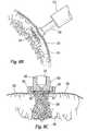
- FIG. 1Ais a schematic representation of an embodiment of a prior art injection system having an externally attached syringe or ampule.
- FIG. 1Bis a schematic representation of an embodiment of a prior art injection system having an internally housed syringe or ampule.
- FIG. 2Ais a perspective view of one embodiment of a nozzle assembly for coupling to a delivery/injection system of the present invention for use in a direct surgical application.
- FIG. 2Bis a lengthwise cross-sectional view of one configuration of a nozzle body of the present invention.
- FIG. 2Cis a perspective view of the nozzle body of FIG. 2B wherein channels located on the distal end of the nozzle body facilitate delivery of an injected solution from an ampule reservoir to dispersion orifices.
- FIG. 3shows a scaled view of the distal end configuration of an injection device of the present invention.
- FIG. 4Ais a view of the distal end of one embodiment of a dispersion fixture of the present invention having a plurality of dispersion orifices.
- FIG. 4Bis an underside view of the dispersion fixture of FIG. 4A illustrating the location and configuration of channels which facilitate delivery of an injected solution from an ampule reservoir to dispersion orifices.
- FIG. 4Cis a cross-sectional side view of the dispersion fixture of FIGS. 4A and 4B.
- FIG. 4Dis a magnified view of the cut-away portion of FIG. 4C defined by circular line D, illustrating the details of the configuration of a particular embodiment of a dispersion orifice having a jewel operatively positioned within it.
- FIG. 4Eis a magnified cut-away view similar to that of FIG. 4C, illustrating another embodiment of a dispersion orifice suitable for use with the present invention.
- FIG. 5is a magnified cross-sectional view of the nozzle body of FIG. 2A operatively coupled with another embodiment of a dispersion fixture of the present invention.
- FIG. 6Ais a view of the underside of another embodiment of a dispersion fixture of the present invention having circular shape and a plurality of dispersion orifices symmetrically aligned along the perimeter of the fixture and being equidistant from the focal point of the fixture.
- FIG. 6Bis a view of the underside of another embodiment of a dispersion fixture of the present invention also having circular shape and a plurality of dispersion orifices but with the orifices having varying distances from the focal point of the fixture.
- FIG. 6Cis a view of the underside of another embodiment of a dispersion fixture of the present invention having an oval shape and a plurality of dispersion orifices with varying distances from the focal point of the fixture.
- FIG. 6Dis a view of the underside of yet another exemplary embodiment of a dispersion fixture of the present invention having the shape of a baseball diamond.
- the plurality of dispersion orificesare equidistant from the focal point and are aligned along the perimeter but only along the length of the arched side.
- FIG. 7Ais a cross-sectional front view of another embodiment of the present invention having a dispersion fixture that provides a solution flow path transverse to the tissue surface being targeted.
- This embodimentalso features malleable tubing connecting the dispersion fixture to the ampule to provide for more flexibility and range of motion.
- FIG. 7Bis a magnified bottom view of the dispersion fixture of FIG. 7 A.
- FIG. 7Cis a view of the jewel plate of the dispersion fixture of FIG. 7 B.
- FIG. 7Dis a cross-sectional side view of the jewel plate of FIG. 7 C.
- FIG. 7Eis a top view of an alternate embodiment of a jewel plate for use with the present invention.
- FIG. 8Ais a perspective view illustrating an embodiment of a solution injection system of the present invention in use in a cardiac surgical procedure.
- FIG. 8Billustrates use of an embodiment of a solution injection system of the present invention operatively positioned on the epicardium to treat an ischemic portion of the myocardium (shown in cross-section) affected by a subendocardial infarct.
- FIG. 8Cis a cross-sectional view illustrating use of the dispersion fixture of FIG. 6A operatively positioned on the epicardium to treat an ischemic portion of the myocardium affected by a transmural infarct.
- FIG. 8Dis a cross-sectional top view of another embodiment of a solution injection system of the present invention employing the dispersion fixture of FIG. 6D operatively positioned on the epicardium to treat a ischemic portion of the myocardium affected by a transmural infarct
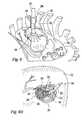
- FIG. 9is a perspective view illustrating an embodiment of a solution injection system of the present invention in use in a less invasive cardiac surgical procedure.
- FIG. 10is a perspective view illustrating another embodiment of a solution injection system of the present invention in use in a less invasive cardiac surgical procedure.
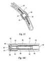
- FIG. 11Ais a longitudinal view of the general configuration of a catheter dispersion means and ampule nozzle assembly for an embodiment of a solution dispersion means for use in endovascular applications.
- FIG. 11Bis a cross-sectional view along the length of the nozzle assembly of FIG. 11 A.
- FIG. 11Cis a perspective view of the coupler of FIG. 11 B.
- FIG. 11Dis a cross-sectional view along the length of the coupler of FIG. 11 C.
- FIG. 11Eis a magnified cross-sectional view of the hypotube tip of the coupler of FIGS. 11C-D.
- FIG. 11Fis a perspective view of an embodiment of a retainer for use with the dispersion means of FIG. 11 A.
- FIG. 11Gis a perspective view of another embodiment of a retainer for use with catheter-based solution dispersion means of the present invention.
- FIG. 12is a side view of one embodiment of a side-shooting catheter tip for use with catheter-based solution dispersion means of the present invention.
- FIG. 13Ais a top view of a portion of cardiac vasculature in which another embodiment of a side-shooting catheter tip is shown in use in a transvascular application.
- FIG. 13Bis a cross-sectional view of FIG. 13A taken transverse to the longitudinal axis of the catheter and vessels.
- FIG. 14Ais a top view of a portion of a coronary artery affected by atherosclerotic stenosis having another embodiment of a side-shooting catheter tip of the present invention operatively positioned proximally of the stenotic region.
- FIG. 14Bis a top view of a portion of a coronary artery affected by atherosclerotic stenosis having the catheter tip of FIG. 14A operatively positioned distally of the stenotic region.
- FIG. 15is a top view of a portion of a coronary artery affected by atherosclerotic stenosis having another embodiment of a side-shooting catheter tip comprising angioplasty capabilities, and which is operatively positioned at a stenotic region.
- FIG. 16Ais a perspective view of an embodiment of an end-shooting catheter tip for use with a catheter-based solution dispersion means of the present invention.
- FIG. 16Bis a longitudinal cross-sectional view of the catheter tip of FIG. 16 A.
- FIG. 16Cis a longitudinal cross-sectional view of the catheter tip of FIG. 16A operatively positioned in the end of a catheter for use with a solution dispersion means of the present invention.
- FIG. 17illustrates an end-shooting catheter-based dispersion means of the present invention in use in an intra-chamber application for delivering a solution to the endocardium.
- FIG. 18Aillustrates a multi-orifice embodiment of a multi-orifice, end-shooting catheter-based dispersion means of the present invention in use in an intravascular application for delivering a solution to within a peripheral vessel.
- FIG. 18Bis a magnified cut-out view of the catheter tip of the dispersion means of FIG. 18A ejecting a solution to treat a thrombus.
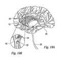
- FIG. 19Ais a cross-sectional view of a medial portion of a human brain wherein a multi-orifice, end-shooting catheter-based dispersion means has been to delivered to a site within the neurovasculature.
- FIG. 19Bis a magnified cut-out view of the catheter tip of the dispersion means of FIG. 19A ejecting a solution to treat a thrombus.
- the present inventionincludes injection systems and methods for injecting and delivering an agent or solution to a target site in the body for the treatment or diagnosis of that target site.
- the injection systemscomprise, at least in part, a propulsion device, a reservoir, often called a syringe or ampule, for receiving and holding the agent or solution, and dispersion means for transferring the agent or solution from the reservoir to the target site.
- the propulsion device of the present inventionmay have a configuration similar to current needle-free injection devices, commonly referred to as jet injectors. Some of these devices include those made by National Medical Products, Inc., BioJect, Inc., MediJect, Inc., Weston Medical Ltd, Visionary Medical Products Corp. and Equidyne Systems, Inc. that are primarily designed for hypodermic applications, such as for the delivery of insulin for the treatment of diabetes. PowderJect Pharmaceuticals PLC is another manufacturer specializing in the needle-free injection of atomized solid materials. These injection devices are capable of injection in the range from about 2000 to about 4500 psi. Examples of such injection devices are disclosed in U.S. Pat. Nos. 5,383,851; 5,399,163; 5,520,639; 5,730,723; 5,746,714; and 5,782,802, which are hereby incorporated by reference.
- FIGS. 1A and 1Bare schematic drawings of exemplary prior art injection or propulsion devices which, with certain modifications, can be used with the present invention as a propulsion device.
- propulsion device 10has a syringe or ampule 18 attached to the distal end 12 of propulsion device 10 .
- Ampule 18may be reusable (refillable) or may be disposable and replaceable with other sterilized ampules.
- FIG. 1Billustrates another embodiment of a propulsion device 20 of the present invention which has an ampule 28 (shown in phantom) housed within the distal end 22 of propulsion device 20 . With this internal ampule design, an entirely disposable injection device is feasible.
- the ampules of both embodimentsmay be supplied pre-filled with a selected volume of the injectable solution.
- Propulsion devices 10 , 20each include a housing 14 , 24 , respectively, which is preferably made of biocompatible plastic, and preferably have a general shape, size and weight so as to readily fit in a users hand.
- Housing 14 , 24houses a propulsion mechanism (not shown), typically either a spring-loaded mechanism or self-contained volume of gas, such as carbon dioxide, helium, argon or nitrogen. The gas is contained within a sealed cartridge that may be interchangeable with other cartridges.
- Other propulsion mechanismssuch as those driven by electromechanical or hydrolic power may also be used with the present invention.
- the propulsion mechanismreleases its potential force to supply an appropriate amount of pressure or force to the proximal end of a piston (also not shown).
- the distal end of the pistonis typically positioned within the proximal end of an ampule and impinges on the volume of solution within the ampule reservoir causing its contents to be forced out the reservoir.
- the propulsion devices of the present inventionmay employ any appropriate propulsion mechanism capable of providing a force having a pressure preferably in the range from about 1800 psi to about 5000 psi. With respect to some of the specific applications discussed below, acceptable pressures may be in the range from about 1800 psi to about 2300 psi.
- the most appropriate pressure for a given applicationwill primarily be dictated by the viscosity of the injectate, the desired depth of penetration, and the type and thickness of the tissue or substance being injected, i.e., muscular tissue, vascular tissue (e.g., cardiovascular, peripheral and neuro), collagen, ocular tissue, cartilage, a tumor, fibrous substances (e.g., thrombus), blood-borne substances (e.g., plaque), etc. Too low of an injection pressure will result in a lack of penetration and dispersion of the injectate while too great of an injection pressure may result in trauma to the tissue site, possibly to the point of puncturing or rupturing the tissue, and overshooting the injectate beyond the desired penetration depth.
- the propulsion mechanism of propulsion devices 10 , 20is activated by means of a trigger mechanism 16 , 26 , respectively, ergonomically located for activation by a user's finger.
- the propulsion mechanismsupplies the requisite force or pressure to ampule 18 , 28 , respectively, causing the solution within to be propelled from injection device 10 , 20 through a dispersion means or mechanism (not shown) which in turn channels the solution to the targeted site.
- the propulsion devices of the present inventionmay comprise components that allow the user, prior to activation of the propulsion mechanism, to select the desired volume of solution to be delivered to the target site and/or the desired pressure at which the solution is propelled from the reservoir.
- the dispersion means of the present inventionis the component of the injection system that directs the agent or solution from within the syringe or ampule to the target site.
- Such dispersion meansis defined by the configuration of an end effector assembled or affixed to the distal end of the propulsion device or ampule reservoir of the injection system.
- the specific configuration of the end effectorprimarily depends on the approach being used to access the targeted tissue site within the body.
- the various approachesinclude a direct surgical approach (or surgery), a less invasive surgical approach through a small incision or port, or an endovascular approach (sometimes referred to as a catheter-based approach).
- the end effector for use in a direct or less-invasive surgical approachis more likely to be in the form of a fixture having openings for dispersing the injectate.
- the fixturemay have a very low profile fixture and an may incorporate means for facilitating delivery through a tortuous and lengthy access space.
- the end effector for use in an endovascular approachis in the form of a catheter. Regardless of the approach used, none of the end effectors of the present invention is designed or intended to penetrate or pierce the target site directly. Instead, only the agent or solution being injected by the present invention is intended to penetrate the target site with minimal trauma to tissue or adjacent substances.
- the injection systems of the present inventionare capable of achieving the desired delivery and dispersion of an injectate to the target site without directly contacting the tissue, if so desired.
- the dispersion means of the present invention for use in a direct surgical approach for accessing a target site on the outer surface of an organ or bodily tissueincludes a non-penetrating end effector or fixture, such as a cap, mounted to or integral with the distal end of the propulsion device (such as with injection system 20 of FIG. 1 B).
- the dispersion meansmay be assembled with an ampule in a nozzle configuration, which in turn is functionally coupled to the distal end of the propulsion device (such as with injection system 10 of FIG. 1 A).
- FIG. 2Ais a perspective view of an embodiment of an end effector integral with a nozzle assembly 30 for attachment to a propulsion device such as that of FIG. 1 A.
- Nozzle assembly 30includes an ampule body 32 and end effector 40 .
- Ampule body 32has a generally cylindrical configuration, and preferably has a length in the range from about 3 cm to about 4 cm and an outer diameter in the range from about 1.2 cm to about 1.5 cm. Of course, these dimensions may vary greatly depending on the clinical application, the amount of solution to be delivered and possibly the distance from the surgical incision to the targeted tissue.
- Nozzle assembly 30 and its componentsare preferably comprised of a biocompatible material, preferably a plastic such as polycarbonate.
- Nozzle assembly 30may be integral with or releasably coupled to the propulsion device.
- FIG. 2Billustrates one configuration of the nozzle assembly 30 of FIG. 2 A.
- Ampule body 32defines an ampule reservoir 34 therein.
- Reservoir 34preferably has a volume sufficient to hold at least one dose of an agent or solution, but may have any size volume to accommodate any number of appropriate doses for a given application.
- the distal end portion 35 of reservoir 34(approximately the most distal of reservoir 34 ) has a distally tapered configuration that terminates in a single reservoir orifice 36 .
- the diameter of reservoir orifice 36is within the range from about 1.1 mm to about 1.3 mm.
- Proximal to distal end portion 35 , reservoir 34has a diameter in the range from about 0.75 cm to about 1 cm.
- the proximal end 60 of ampule body 32has a flanged configuration having mounting flanges 62 for mating with corresponding flange recesses of the distal end of an injection system (not shown) of the kinds described with reference to FIGS. 1A and 1B.
- FIG. 3illustrates a corresponding mating configuration with flange recesses 72 at the distal end 74 of an injection system 70 having a general design similar to that of the external ampule embodiment of FIG. 1 A.
- This mating configurationis some times referred to as a bayonet mount configuration.
- an end effector 40in the form of a dispersion fixture or cap, having a generally circular shaped distal portion 44 and an annular wall portion 46 .
- Distal portion 44has a smooth, generally planar, distal target-facing surface 45 .
- Distal portion 44may also have a constant, downward grade (not shown) of approximately 3% from its perimeter to its center. This provides a slightly concave surface to match that of the tissue surface in order to ensure equidistance between each of the dispersion orifices (discussed below) and the tissue surface, and if so desired, to maximize contact between target-facing surface 45 and the tissue surface.
- a suction mechanism associated with ampule body 32may be employed to apply a negative pressure to the surface of the tissue in order to help position end effector 40 .
- the perimeter 48 of the outer surface of distal portion 44is beveled so as to be atraumatic to the tissue if target-facing surface 45 comes into contact with tissue.
- Dispersion fixture 40has an external diameter in the range from about 1.75 cm to about 1.9 cm, and an internal diameter in the range from about 1.3 cm to about 1.6 cm.
- Distal portion 44also has a plurality of spaced-apart dispersion orifices 37 bored through the entire thickness of distal portion 44 .
- dispersion orifices 37have a slightly distally tapered configuration at their distal end to facilitate delivery of solution there through.
- four dispersion orifices 37are shown (see FIG. 2A) but any number of dispersion orifices may be employed with the present invention.
- Dispersion orifices 37are oriented in a quadrangle configuration to evenly disperse the injectate over or within a relatively broad area of the targeted site; however, any appropriate arrangement of the dispersion orifices, whether symmetrical or asymmetrical, and any appropriate spacing between the orifices may be employed with the present invention. Other possible orifice configurations are discussed below with reference to FIGS. 6A-D.
- At least one reservoir orifice and at least one dispersion orificeare necessary for the proper functioning of the injection systems of the present invention.
- an end effector employing one or more dispersion orificesmay be used with only a single corresponding reservoir orifice.
- a one-to-one correspondence between dispersion and reservoir orificesmay be employed.
- any suitable number of dispersion orificesmay be used with any suitable number of reservoir orifices.
- the present inventionmay also include the use of fluid pathways or channels between the dispersion and reservoir orifices. These pathways are preferably integral with either the ampule or the end effector of the present invention.
- channels 52are milled or machined within the distal surface 54 of ampule body 32 .
- Dispersion orifices 37terminate proximally at channels 52 , respectively (discussed more thoroughly below with respect to FIG. 5 .
- Channels 52define the delivery pathways through which a solution is caused to travel as it is ejected or expelled from reservoir orifice 36 . The solution is then caused to flow through and be ejected from respective dispersion orifices 37 .
- FIG. 5there is shown a cross-sectional view of ampule body 32 of FIG. 2A which more clearly illustrate the location and configuration of channels 52 within distal surface 54 .
- ampule body 32is coupled to another embodiment of a dispersion fixture 96 .
- Juxtaposed between and in sealing engagement with the annular wall 95 of dispersion fixture 96 and ampule body 32is an annular sleeve 50 for providing a fluid-tight seal to prevent against leakage of the solution held within ampule reservoir 34 .
- Annular sleeve 50has a wall height equivalent to that of annular wall 95 , and external and internal diameters suitable for annular sleeve 50 to be fit snuggly between annular wall 95 and ampule body 32 .
- Fixture 96has dispersion orifices 98 having a configuration different from that of the dispersion fixture 40 of FIG. 2B, and which will be more thoroughly discussed below with respect to FIGS. 4C and D.
- FIGS. 4A-Dthe details of another embodiment of a dispersion fixture 43 are illustrated.
- FIG. 4Ashows the distal portion 58 of dispersion fixture 43 having four dispersion orifices 42 bored through the entire thickness of distal portion 58 .
- the cross-sectional cutaway view of FIG. 4Dshows each orifice 42 having a proximal portion 42 a , a central portion 42 b and a distal portion 42 c .
- Proximal portion 42 ahas a cylindrical configuration having a diameter in the range from about 1.0 mm to about 1.3 mm.
- Central portion 42 balso has a cylindrical configuration having a diameter in the range of about 0.1 mm to about 0.6 mm, and more preferably in the range of about 0.1 mm to about 0.3 mm.
- Distal portion 42 chas a cone-like configuration with the narrow end adjacent to and contiguous with central portion 42 b , and flaring to a diameter that is approximately twice that of central portion 42 b . This orifice configuration provides a wider range of dispersion, preferable when targeting larger areas of tissue.
- dispersion fixture 49has a dispersion orifice 80 bored through the entire thickness of dispersion fixture 49 .
- Orifice 80has a funnel shape cross-section, ending in a tubular distal portion 80 a having a diameter in preferably in the range from about 0.1 mm to about 0.3 mm.
- the length of tubular distal portion 80 ais approximately 2 to 5 times greater than the diameter. This design is more suitable when dispersing solution in a smaller area of tissue.
- FIG. 4BAnother embodiment of the solution channels of the present invention is seen in FIG. 4B, illustrating the underside 51 of distal portion 44 of dispersion fixture 43 .
- the channels 57are cut or milled within the dispersion fixture itself. Milled to a depth of about 0.5 mm, channels 57 intersect at a central focal point 56 that is concentrically aligned with the reservoir orifice of an ampule body (not shown). Channels 57 extend radially outward and terminate, respectively, at a corresponding dispersion orifice 42 .
- a jewel or crystal 66having a disk configuration with a central bore 67 .
- Jewel 66is preferably made of a hard material that can be precisely cut to form a uniform exit path for an ejected solution. Suitable materials include stainless steel or precious stones, such as sapphire or ruby.
- a jewelis preferably used to ensure an accurate and precise vector path of an ejected solution.
- Each jewelhas a diameter sufficiently sized to allow jewel 66 to be press-fit into jewel chamber during the assembly process.
- Central bore 67preferably has a diameter from about 10% to about 15% of the diameter of jewel 66 .
- any suitable dispersion orifice, reservoir orifice, and channel configuration and patternare contemplated for use with the present invention.
- the particular dispersion orifice (and reservoir orifice) configuration to be usedmay depend on several factors including the medical condition being treated, the gross morphology of the tissue area or other target site being treated, the type of access provided for delivery of the device and the viscosity and dispersion characteristics of the injectate. For example, from what is currently known about angiogenesis, a better angiogenic outcome is more likely where the angiogenic solution has at least some healthy tissue in which to initiate the grown of new vessels.
- the angiogenic solutionis preferably injected, at least in part, into some healthy tissue immediately adjacent the infarcted area.
- the particular orifice configurationwill likely depend on whether the infarct is a subendocardial infarct or a transmural infarct.
- Subendocardial inifarctsare characterized by multifocal areas of necrosis within the myocardium and are typically confined to the inner surface of the myocardial wall, whereas a transmural infarct involves the entire thickness of the myocardial wall from endocardium to epicardium.
- the quadrangle configuration of the dispersion orifices illustrated in FIG. 4Amay be more suitable for a subendocardial infarct than for transmural ischemia.
- the quadrangle configurationwill likely create a contiguous, relatively expansive dispersion area in the myocardium, allowing the injected angiogenic solution to disperse within the outer layers of healthy tissue confining the subtransmural ischemia.
- a more suitable dispersion fixture for this applicationis, for example, one having a single orifice, a linear array of orifices having an annular configuration (e.g., any shape ring or loop, or an arch configuration) or a straight row(s) of orifices which can be selectively aligned with or immediately proximal to the perimeter of the ischemic area wherein at least some of the angiogenic solution is dispersed within healthy tissue.
- FIGS. 6A-Eillustrate a few exemplary dispersion fixtures of the present invention having various shapes, sizes, orifice patterns and corresponding channel configurations.
- certain dimensionssuch as diameter and angle of curvature
- certain dimensionsshould be assumed to be appropriately analogous to those of previous embodiments, keeping in mind the obvious variances attributable to the specific shape and necessary surface area of the various dispersion fixtures.
- FIG. 6Aillustrates the underside of a dispersion fixture 104 of the kind discussed above with respect to FIGS. 2A-C.
- the orifice configurationincludes twelve ( 12 ) orifices 106 aligned in a ring close to the perimeter of dispersion fixture 104 .
- the spacing between adjacent orifices 106is the same throughout the ring.
- Corresponding to each orifice 106is a channel 108 extending radially from the center 110 of dispersion fixture 104 .
- This particular designis advantageous for injecting an angiogenic solution to treat a transmural infarct, for example.
- dispersion fixture 104attached to an injection device
- dispersion fixture 104attached to an injection device
- dispersion fixtures 104having any number of orifices arranged in any suitable pattern.
- FIG. 6Billustrates the underside of another embodiment of a dispersion fixture 112 having a circular shape and having a plurality of dispersion orifices 114 in a staggered configuration which defines a channel pattern of two sets of symmetrical channels, channel set 116 a (the more proximal, set) and channel set 116 b (the more distal set) having different lengths, i.e., the channel length of channel set 116 a is shorter than that of channel set 116 b .
- This embodimentprovides a more even distribution of injected solution in a defined area, and would be useful, for example, in delivering angiogenic solution to an area of myocardium affected by a subtransmural infarct.
- the pressure and velocity of the injectate through the dispersion orifices 114 of channel set 116 awill likely be slightly greater than that being delivered through the dispersion orifices 114 of channel set 116 b .
- the size and path length (e.g., by means of curving) of one channel setmay be increased or decreased to compensate for the slight deviation.
- FIG. 6Cthere is shown the underside of a dispersion fixture 118 having an oval profile.
- the dispersion orifices 120are similarly aligned close to the perimeter of dispersion fixture 118 ; however, the resulting oval pattern of orifices 120 results in varying lengths of channels 122 . Similar to the embodiment of FIG. 6B, the varying channel lengths will result in correspondingly varying pressures, velocities and volumes of solution exiting each orifice 120 .
- dispersion fixture 118is more suitable for infarcted areas that have a shape and size corresponding to that of fixture 118 .
- the distal end of a nozzle body to be used with dispersion fixture 118necessarily has a design and structure different from that of the previously discussed embodiments. Those skilled in the art will understand these necessary design modifications.
- FIG. 6Dillustrates the underside of yet another possible embodiment of a dispersion fixture 124 of the present invention.
- dispersion fixture 124has a shape in the form of a diamond or of an arched cone.
- Five dispersion orifices 126are aligned in a single, linear array proximate the perimeter of and matching the angle of curvature of annular or arched side 128 of dispersion fixture 124 .
- the included angle 125 at the vertex 123 of dispersion fixture 124may range from a minimum value, defined by the space necessary to accommodate a single dispersion orifice, preferably greater than about 5°, to a maximum value of 360°, such as in the embodiments of FIGS. 6A-C.
- angle 125will ranged from about 20° to about 180°, and even more typically, between about 45° and about 90°, such as with the embodiment of FIG. 6 D.
- dispersion orifices 126are equidistant from the focal point of dispersion, and thus, result in corresponding channels 130 which extend radially outward from the focal point and which have identical lengths.
- the pressure, velocity and volume of solution exiting each dispersion orifice 126will be the same for each.
- the requisite nozzle body design to be used with dispersion fixture 124will differ from those previously discussed. Those skilled in the art will understand the necessary design features required for a compatible nozzle body.
- FIG. 7Ashows a cross-section front view of another embodiment of a dispersion fixture 132 .
- target-facing surface 138 of dispersion fixture 132has an atraumatic, elliptical profile having a length preferably in the range of about 7 mm to about 10 cm and a width in the range of about 2.5 mm to about 4 cm but will vary depending on the target organ or tissue and the size of the tissue area being treated.
- Target-facing surface 138provides a linear array of dispersion orifices 134 in fluid communication with their respective channels 136 which, except for the center orifice, are at varying acute angles to tissue surface 133 when operatively positioned.
- a dispersion fixture configurationis useful, for example, for delivering an angiogenic solution to the epicardium along or lateral to a portion of a coronary artery 135 affected by atherosclerotic plaque 143 .
- an angiogenic solutionsuch as BFGF
- This embodimentis also suitable for delivering a solution (such as ethanol) to the epicardial tissue, such as on the atria, for creating a linear lesion to treat atrial fibrillation.
- target-facing surface 138has a shallow arch configuration so as to maximize contact with the tissue surface 133 . Due to the slightly varying lengths of channels 136 , the pressure, velocity and volume of solution exiting each dispersion orifice 134 will be slightly different. More specifically, the value of these variables will be the greatest for solution exiting the center orifice and the lowest for solution exiting the two outermost orifices. The value of these variables for solution exiting the two orifices positioned in between the central and outermost orifices fall somewhere in between the other two sets of values.
- a nozzle body 140 compatible with dispersion fixture 132 of FIG. 7Ais generally the same as that discussed with respect to the nozzle body embodiment of FIG. 2B; however, the means for functionally attaching dispersion fixture 132 to nozzle body 140 , and thereby functionally connecting reservoir orifice 142 to channels 136 , is different.
- Such a meansis generally referenced as 144 and includes a length of malleable tubing 145 extending from the very distal end 147 of nozzle body 140 to the proximal end 137 of dispersion fixture 132 .
- Tubing 145transports a pressurized solution from within ampule reservoir 141 to channels 136 , respectively, while providing a free range of motion and positioning of dispersion fixture 132 relative to nozzle body 140 .
- Tubing 145is preferably comprised of material(s) that allows it to be malleable.
- One suitable materialis coated wire mesh, which is flexible enough to be contorted and bent but rigid enough to provide stability and to reliably maintain the position of dispersion fixture 132 while solution is being injected into tissue.
- Tubing 145may either define its own lumen 146 or encase a catheter (not shown) co-axially running at least the length of tubing 145 .
- Such a catheteris coupled to reservoir orifice 142 at its proximal end and to channel entrance 139 at its distal end.
- Tubing 145 and/or a co-axial catheterare comprised of material(s) which provide a wall strength sufficient to maintain the pressure and velocity of an injectate being delivered through it.
- the attachment and connecting means 144 just describedis not limited to this embodiment but may be employed with any embodiment of the present invention.
- jeweled substrate or plate 148may be used in lieu of multiple jewels, one for each dispersion orifice as described for the previous embodiments.
- Jeweled plate 148is comprised of any suitable stone or crystal that would be used for the multiple jewel embodiments.
- FIG. 7B(the bottom view of target-facing surface 138 ), FIG. 7C (the magnified top (or bottom) view of jeweled plate 148 ), and FIG. 7D (the cross-sectional side view of jeweled plate 148 ), jeweled plate 148 has a plurality of bores 150 (FIG. 7D) corresponding to the number of and aligned with dispersion orifices 134 .
- a single substrate or platehas the advantage of being easier to fabricate and easier to handle and position within dispersion fixture 132 during the manufacturing process.
- FIG. 7Eillustrates an alternative configuration of a jeweled substrate 152 .
- Jeweled substrate 152has a narrow stem portion 154 having a plurality of outposts 155 along one side of stem portion 154 .
- Each outpost 155has a jewel 156 attached to its distal end.
- Substrate 152 and outposts 155may be made of the jewel material being used or another rigid material.
- One skilled in the artwill recognize that other suitable embodiments of the jewel piece(s) may be used with the present invention.
- dispersion fixtureshave been described for use in surgical applications, one skilled in the art can appreciate that other shapes and sizes of dispersion fixtures and any number and configuration of orifices may be employed with the present invention.
- a dispersion fixture of the present inventionhaving a relatively small target-facing surface and only a single dispersion orifice may be useful for accurately and precisely delivering solution to small, discrete areas of tissue, such as an area of infarcted myocardium having diffuse locations of ischemia.
- An embodiment having a dispersion fixture that is comprised of a relatively flat, thin, malleable sheathmay be useful to treat oddly shaped or difficult to reach tissue, say for example, the back side of the liver or a tumor within the intestinal area whose dimensions and shape are not readily known until exposed.
- FIGS. 8A-Dillustrate various embodiments of injection systems of the present being used in a thoracic or cardiothoracic surgical application, for example, to deliver and inject angiogenic growth factor for initiating angiogenesis within the myocardium or within a coronary vessel.
- the solution delivery procedure in the context of an open cardiac surgical procedurewill be adjunct to a CABG or valve replacement or repair procedure.
- the solution delivery proceduremay be performed prior to or after the other surgical procedure and may be done on or off-pump.
- Solution injection system 200has an injection portion 202 , having a general structure in the form of a gun, and an ampule 204 distally attached to injection portion 202 .
- Ampule 204holds the angiogenic solution to be delivered.
- Attached distally to ampule 204is a dispersion fixture 206 in the form of cap similar to the embodiment of FIGS. 2A-C.
- dispersion fixture 206is shown being held against and in direct contact with the epicardium in an area of infarcted tissue 216 (outlined in phantom); however, direct contact is not required for performing the methods of the present invention with any of the devices of the present invention.
- a robotic mechanismmay be used.
- the dispersion fixture 206is positioned adjacent or proximate to the target tissue area.
- the propulsion mechanism(such as the ones discussed above with respect to FIGS. 1A and 1B) internal to injection portion 202 is activated by means of a trigger mechanism (not shown) to provide the requisite force to drive the solution out of ampule reservoir 204 , into and through dispersion fixture 206 having a suitable size and shape for the application at hand.
- the internal configuration of dispersion fixture 206channels the solution flow through a defined path or paths which optimize the volume and pressure of solution being injected at the desired point(s) within the target area.
- the highly pressurized injectateis then dispersed throughout the selected area. This procedure may be repeated as necessary for treating one or more targeted sites.
- FIG. 8Billustrates use of solution injection system 215 of the present invention to treat a portion of myocardium 214 affected by subendocardial ischemia.
- the dispersion fixture 218 of solution injection system 215is preferably of the type illustrated in FIGS. 2A-C and 4 A-E. Operatively positioned on epicardium 213 , this configuration allows for the jet delivery of angiogenic solution into the healthy layer of tissue directly over ischemic area 212 . This allows for the angiogenic growth factors to initiate the creation of new vessels within the healthy area.
- FIG. 8Cillustrates use of another injection system 220 of the present invention for the treatment of a portion of myocardium 222 affected by a transmural ischemic area 224 , wherein the affected area 224 spans the thickness of myocardium 222 from endocardium 226 to epicardium 228 .
- Solution injection system 220has an ampule body 221 housing reservoir 223 with a dispersion fixture 230 mounted thereto.
- dispersion fixture 230is of the type illustrated, for example, in FIG. 6A, wherein a plurality of dispersion orifices 232 arranged annularly and proximate to the perimeter of dispersion fixture 230 .
- the diameter of the annular configuration formed by dispersion orifices 232is preferably slightly greater than the diameter of infarcted area 224 (assuming the infarct has a generally annular shape itself; otherwise, a more appropriate shaped dispersion fixture should be used).
- the angiogenic solutionis injected into or dispersed to at least some of the healthy tissue proximate the perimeter 225 of ischemic area 224 so as to further ensure the genesis of new blood vessels.
- FIG. 8Dillustrates use of yet another injection system of the present invention.
- This embodimenthas a dispersion fixture 234 having the configuration of the type illustrated in FIG. 6D, which is also suitable for use in treating an ischemic area 250 of a heart wall 252 created by a transmural infarct.
- FIG. 8Dprovides a cross-sectional top view of dispersion fixture 234 illustrating an annular array of dispersion orifices 236 aligned along and proximate to the perimeter of arched portion 235 of fixture 234 .
- dispersion fixture 234is coupled to a rigid shaft 242 that extends from an ampule body (not shown).
- Fixture 234 and shaft 242are preferably coupled by a hinged-type joint mechanism 243 (not shown in detail) that allows dispersion fixture 234 to be selectively pivoted and locked in place with respect to shaft 242 .
- Dispersion fixture 234has a range of motion preferably from about 30° to about 110° with respect to the longitudinal axis of shaft 242 . This range of motion allows a user more flexibility to treat difficult to reach tissue areas, such as on the posterior side of the heart.
- Various configurations of such a joint mechanismare commonly known by those skilled in the art.
- tubing 240Running coaxially with the lumen of shaft 242 is flexible tubing 240 that provides a conduit for transporting a pressurized solution between an ampule reservoir (not shown) and dispersion fixture 234 .
- Tubing 240is flexible enough and has sufficient slack along its length to allow for the variable positioning of dispersion fixture 234 with respect to shaft 242 .
- Tubing 240is preferably comprised of high tensile strength plastic or silicone reinforced with stainless steel ribs or wound wire in order to maintain a desired solution pressure and velocity throughout the injection cycle.
- Distal end 244 of tubing 240terminates at an opening to the entrance of solution channels 238 each of which extend radially to a respective dispersion orifice 236 .
- the physician or other userprior to each injection, will have the option to adjust the position of the dispersion fixture with respect to the injection device to optimize the delivery and dispersion of a solution.
- Thisincludes either adjusting (e.g., bending, angling, etc. as appropriate) the dispersion fixture, or the means for coupling the dispersion fixture to the ampule, or both.
- dispersion fixture configurationfor a particular clinical application will depend on several factors, including but not limited to, accurately assessing the condition to be treated (e.g., subendocardial ischemia vs. transmural ischemia), the size, shape and thickness of the tissue area being treated, the depth of the area from the tissues surface, the location of the treatment area (i.e., the organ being targeted), and the ease of access or lack thereof to the targeted locations.
- dispersion orifice configurationincluding the number of orifices, the size of the orifice(s) and the arrangement of orifices, will depend on several factors, including but not limited to, the pressure profile of the propulsion device being used, the viscosity of the injectate, and the size of the surface area of the target site.
- the present inventioncan also be configured for delivering a solution to a targeted site within the body in the context of a less invasive surgical procedure.
- the means of access for less invasive surgeries, particularly for a minimally invasive cardiac surgeryis typically accomplished by means of a very small incision or a positioned through the skin.
- the portis created within the patients chest cavity or through a mini-thoracotomy or other minimally invasive incision in the chest area.
- a port access approachmay require the use of a trocar, an elongated tubular device that provides a conduit from outside the body to the target area within the body.
- a larger but still less invasive incisionmay not require use of a trocar but may still require the use of smaller and preferably flexible or malleable tools to access the more difficult to reach areas. Still other less invasive procedures involve the use of an endoscope to facilitate visualization while performing the surgery.
- the injection devices described above for use in the injection systems of the present invention for direct surgical applicationsare also suitable for use in injection systems for less invasive surgical applications. It is the configuration of the dispersion means of the less invasive systems, as defined by the particular end effector being used, which necessarily has a slimmer or lower profile than those of the systems for surgical applications.
- the specific design of the end effector for a less invasive surgical approachwill primarily depend on such factors as, including but not limited to, the location of the treatment area (i.e., the organ being targeted) and the ease of access or lack thereof to the treatment area.
- the configuration of the dispersion meansmay also depend on whether the solution delivery procedure is adjunct to another procedure, such as a CABG or a valve repair or replacement procedure, or is the sole procedure being performed.
- the pericardiumwill have been incised to access the heart, possibly requiring only minor modifications to the dispersion means of the present invention, some of which are described below.
- a solutione.g., such as an antibiotic for the treatment of pericarditis or myocarditis
- a solutionmay be injected with the present invention directly through the pericardium so as to fill the pericardial space (i.e., intrapericardial injection) for prolonged exposure to the pericardium or the myocardium.
- a solutione.g., such as an angiogenic solution for treating ischemic myocardial tissue
- FIG. 9is a view of a heart from within the thoracic cavity and an embodiment of a dispersion means 260 operatively positioned to treat an area of the myocardium 254 .
- Dispersion means 260includes a cylindrical shaft 261 coaxially positioned within a trocar port 265 operatively positioned between two adjacent ribs 256 .
- Dispersion means 260further includes a dispersion fixture 262 attached to the distal end of shaft 261 shown here to be in operative contact with a targeted area 258 of the hearts epicardium.
- Dispersion fixture 262has a configuration generally similar to those illustrated in FIGS. 8A-C. However, here, dispersion fixture 262 has a diameter (or other transverse dimension depending on the shape of the fixture) small enough to fit through trocar port 265 and may have any suitable shape and dispersion orifice configuration (similar to those discussed above with respect to embodiments for surgical applications) for the application at hand.
- Shaft 261defines an internal space comprising either an ampule reservoir (not shown), similar to those described above for surgical applications, or a lumen (not shown) for transporting solution from an ampule reservoir (located either proximally within shaft 261 or within the injection device itself) to dispersion fixture 262 .
- the reservoirhas length and diameter dimensions suitable for being housed in shaft 261 and for defining a volume sufficient to hold at least a single dose of solution.
- FIG. 9A method of using the embodiment of FIG. 9 will now be discussed in the context of a minimally invasive cardiac procedure in which a solution is being delivered to a target area 253 on the epicardium.
- a small incisionis made at the desired location (e.g., between adjacent ribs 256 )
- trocar 265is positioned within the incision.
- Dispersion means 260is then inserted into the proximal end of trocar 265 and moved coaxially within trocar 265 until dispersion fixture 262 is delivered to a desired distance from or in contact with the target tissue.
- the systemWith the ampule reservoir filled with the desired amount of solution and the injection mechanism of the injection system properly set for fuing, the system is actuated, causing the solution to be ejected from the ampule reservoir and delivered through shaft 261 to dispersion fixture 262 .
- the dispersion orifices(not shown) then directed the solution to various sites within the target area.
- Dispersion means 270in use in a less invasive cardiac procedure in which access to the heart is accomplished through an opening made, for example, in the region just below the patient's xyphoid 280 (i.e., subxyphoid).
- Dispersion means 270comprises a malleable catheter or tubing 274 which, at its proximal end, is in sealing engagement with the orifice of an ampule reservoir (not shown), and extends distally to dispersion fixture or catheter tip 275 .
- Tip 275has at least one dispersion orifice.
- tubing 274is preferably comprised of a strong yet flexible medical grade material, such as nitinol, nylon, or polyimide reinforced with stainless steel or Kevlar, and may have any suitable length for the application at hand.
- Tubing 274has outer and inner diameters suitable for connection to an ampule reservoir orifice and for coaxial alignment within a cannula or tubing 278 .
- a port 272has been positioned within a subxyphoid incision, for example, to provide access to within the thoracic cavity of the patient.
- This port configurationis more suitable for penetration through the diaphragm 282 rather than between the ribs such as trocar 235 of FIG. 9.
- a flexible, steerable cannula or tubing 278extends proximally from and is in sealing engagement with port 272 .
- Tubing 278is preferably comprised of material mentioned above with respect to tubing 274 of FIG. 10, and may have any suitable length for the application at hand.
- FIG. 10A method of using the embodiment of FIG. 10 will now be discussed in the context of a minimally invasive cardiac procedure in which a solution is being delivered to a target area 284 on the epicardium.
- port 272 and the attached cannula 278are positioned within the incision.
- Tubing 274is shaped into a desirable configuration and then inserted into the proximal end of cannula 278 .
- the malleability of catheter 274allows it to be shaped in a configuration that will more readily facilitate navigation of catheter tip 275 to the target area(s).
- cannula 278allows it to comply with the shape of the catheter being inserted into it and further increases ease of access to the target area(s).
- Catheter 274is then steered distally through cannula 278 until catheter tip 275 is delivered to a desired distance from or in contact with the target tissue 284 .
- the systemWith the ampule reservoir filled with the desired amount of solution and the injection mechanism of the injection system properly set for firing, the system is actuated, causing the solution to be ejected from the ampule reservoir and delivered through catheter 274 to the dispersion orifice at tip 275 , which precisely directs the solution to a selected site within the target area 284 .
- an endoscope and a light sourcemay be used with the process just described in order to facilitate visualization by the surgeon of the surgical area.
- this embodimentallows solution to be delivered to areas that are very difficult to reach, particularly through a less invasive incision.
- the deviceis capable of delivering solution to a target area of tissue on the posterior side of the heart.
- this configurationmay also be suitable for injecting a solution directly through the pericardial sac.
- the dispersion means of the present invention for use in endovascular applicationsincludes a catheter assembly having an end effector in the form of a catheter tip to access a target site within an organ, a tumor, a body or vessel lumen, or an artificial graft lumen.
- Some applicationsinclude, for example, accessing a target area on the inside surface of the heart (i.e., the endocardium), within the cardiac vasculature (such as the aorta, or a coronary artery or vein), within the peripheral vasculature (such as the iliac, femoral, popiteal and infrarenal), within the neurovascular systems (such as the carotid artery) or to a tumor via the vasculature from which it receives its blood supply.
- a target area on the inside surface of the hearti.e., the endocardium
- the cardiac vasculaturesuch as the aorta, or a coronary artery or vein
- peripheral vasculaturesuch as the iliac, femoral, popiteal and infrarenal
- the neurovascular systemssuch as the carotid artery
- the endovascular approachesinvolve inserting a catheter of the present invention through a percutaneous incision made within a vessel, such as the femoral artery, subclavian artery, the carotid artery or other suitable vessel, and delivering the catheter tip to a target site by means of a guide wire (e.g. over-the-wire, rapid exchange or monorail catheterguide wire configuration) or a guiding catheter, many of which are commonly used in the art.
- a guide wiree.g. over-the-wire, rapid exchange or monorail catheterguide wire configuration
- a guiding cathetere.g. over-the-wire, rapid exchange or monorail catheterguide wire configuration
- Such a catheteris configured for attachment to the distal end of an ampule (such as the embodiment of FIG. 1A) or directly to the distal end of an injection device (such as the embodiment of FIG. 1 B).
- FIG. 11Aillustrates an embodiment of a dispersion means 300 of the present invention for use in endovascular applications.
- Dispersion means 300includes catheter assembly 304 integrally coupled to an ampule body 308 defining a reservoir 310 by means of a retainer 311 threaded over the distal end 309 of ampule body 308 .
- Proximal end 307 of ampule body 308defines a bayonet mount for coupling to the distal end of an injection system (such as injection system 10 of FIG. 1 A).
- Retainer 311generally has a similar shape and size as the dispersion fixtures discussed above with respect to the intraoperative devices illustrated; however, retainer 311 does not provide a solution dispersion function but, instead, provides a means for securely retaining the attachment of catheter assembly 304 to ampule body 308 , particularly during an injection cycle. Juxtaposed between and in engagement with retainer wall 303 of retainer 311 and ampule body 308 is an annular sleeve 305 , which further ensure retention of catheter assembly 304 to ampule body 308 when under the high pressures of an injection cycle.
- distal portion 309 of ampule body 308terminates in an annular wall 312 and a reservoir nozzle 313 extending from reservoir orifice 316 .
- Reservoir nozzle 313is centrally and coaxially positioned within annular wall 312 , and both extend about 7.5 mm proximally of ampule body 308 , and collectively define a toroidal shaped space 315 between them.
- Reservoir nozzle 313has a centrally disposed, narrow lumen 314 in fluid communication with reservoir orifice 316 .
- Narrow lumen 314as well as reservoir orifice 316 , has diameters in the range from about 0.4 mm to about 0.8 mm.
- Catheter assembly 304includes a catheter 318 attached proximally to a coupler 320 .
- Catheter 318is comprised of material(s) having columnar and wall strengths sufficient to maintain the desired pressure and velocity of an injected solution throughout the injection cycle.
- catheter 318is preferably comprised of two layers, an internal conduit 321 preferably made of a braided polyimide for strength, and an outer sheath 322 preferably comprised of thermoplastic polyether-based polyamide (PEBAX) which provides a soft atraumatic feel.
- PEBAXthermoplastic polyether-based polyamide
- the length and diameter (or size in French units) of catheter 318will depend on the diameter of the vessel providing the delivery path and the distance between the percutaneous entry site and the target site(s) (e.g., coronary artery, carotid artery, iliac artery, femoral vein, subclavian artery, cerebral artery, renal artery, etc.).
- a catheter delivered through a percutaneous site in the femoral artery at the patients groin to a location within the heartpreferably has a length within the range from about 1.3 meters to about 1.7 meters, and more preferably a length of about 1.5 meters.
- a catheter to be delivered to within a coronary arteryfor example, likely has an outer diameter that is smaller than that which is delivered to a heart chamber such as the left ventricle, and is preferably is in the range from about 1.4 mm to about 1.8 mm, or a French size of about 4 to about 6.
- a catheter having a shorter length and possibly a larger outer diametermay be used.
- catheter assembly 304further comprises a coupler 320 , such as a luer subassembly, for coupling catheter 304 into reservoir nozzle 313 .
- a coupler 320such as a luer subassembly
- FIGS. 11C and Dmore clearly illustrate the configuration of luer subassembly 320 , which generally includes a luer fitting 324 and hypotube 326 extending coaxially from the distal end 328 of luer fitting 324 .
- Luer fitting 324is preferably comprised of stainless steel.
- Luer fitting 324preferably has a length within the range from about 20 mm to about 24 mm, and an outer diameter at the widest portion of the luer wall 323 is in the range from about 6 cm to about 8 mm.
- the cylindrical lumen 325has a slightly distally tapered configuration within which it matingly receives and engages the distal end of reservoir nozzle 313 .
- the profile of distal end 328 of luer fittingtapers somewhat and defines a luer shoulder 338 .
- hypotube 326Centrally disposed within distal end 328 of luer fitting 324 , hypotube 326 is in fluid communication with luer lumen 325 . Hypotube 326 extends distally from its proximal end 330 , flush with the distal end 329 of luer lumen 325 , to a flared distal tip 332 . Like catheter 318 , hypotube 326 is comprised of material(s) that can maintain the desired pressure and velocity of an injected solution throughout the injection cycle, and is preferably made of stainless steel.
- Hypotube 326has a length preferably in the range from about 1.0 cm to about 1.3 cm, an outer diameter preferably in the range from about 0.5 mm to about 0.7 mm, and an inner diameter preferably in the range from about 0.35 mm to about 0.5 mm.
- distal tip 332 of hypotube 326flares outward at a slight angle 334 in the range of about 6% to about 9% from the axis defined by the inside of the tubing wall.
- the flared portion of distal tip 332comprises about 3% to about 5% of the entire length of hypotube 326 .
- the outer diameter at burnished edge 336 of flared tip 332is approximately about 0.01 to about 0.2 mm greater than that of the remainder of the hypotube 326 .
- This tip configurationhelps ensures a tightly sealed fit between hypotube 326 and the proximal end of catheter 318 . More specifically, flared tip 332 and the distal portion of hypotube 326 are inserted into the lumen 321 at the proximal end of catheter 318 , and then sealed to it by means of an epoxy.
- a short metal ferrule 340(having a length just shy of the portion of hypotube 326 which extends from distal end 328 ) is then fit over and crimped around the distal end of hypotube 326 .
- the outer layer or sheath 322 of catheter 318is then slid over and sealed to the entire length of the lumen 321 , including ferrule 340 .
- retainer 311is preferably made of a polycarbonate material and has a centrally positioned bore through its closed end 344 beveled at its perimeter 346 .
- Retainer 311is assembled with nozzle assembly 302 and catheter assembly 304 by passing the distal tip 350 of catheter 318 through the underside of retainer 311 and through bore 342 .
- Retainer 311is then slid over catheter 318 and distal end 328 of luer fitting 324 until closed end 344 buttresses against luer shoulder 338 .
- Bore 342allows retainer 311 to rotate around catheter assembly 304 while it is being manually screwed onto annular sleeve 305 .
- catheter assembly 304 and nozzle assembly 302are now securely engaged with each other.
- FIG. 11Gshows a perspective view of another embodiment of a retainer 352 for use with the present invention.
- the configuration of retainer 352is generally similar to that of retainer 311 of FIG. 11F; however, closed end 355 of retainer 352 has a keyhole shaped slot 354 that runs the height of annular sidewall 356 . With the slotted configuration, retainer 352 can be seated in place without having to slide retainer 352 over the entire length of catheter 318 .
- Slot 354is aligned along catheter assembly 304 just above distal end 328 of luer fitting 324 . After proper alignment, retainer 352 is screwed onto annular sleeve 305 .
- Retainer 352is preferably comprised of aluminum or of another lightweight, rigid metal, rather than of a plastic material as the slotted configuration of retainer 352 makes it more susceptible to failure under the injection pressure if made of plastic.
- catheter tipsfor use with the endovascular devices of the present invention will now be described and discussed.
- the particular design of a catheter tip and its target-facing surface for use with the present inventionwill depend in part on the type of treatment involved. Some applications include, for example, accessing a target area in a chamber or lumen within an organ, within the cardiac vasculature, the peripheral vasculature and the neurovascular systems, or on or in a tumor via the vasculature from which it receives its blood supply. It is also intended that the various catheter tip embodiments be interchangeable with each for attachment to the same catheter.
- the catheter tip designand more specifically the design of the target-facing surface of the tip, will also depend upon the location of the targeted site and the type of tissue or substance being treated. For example, when treating a coronary artery affected by artherosclerotic plaque, such as with an angiogenic solution to promote collateral vessel growth or with another solution such as inducible nitrous oxide synthase (iNOS) to reduce plaque or minimize the likelihood of restenosis, it is preferable to use a catheter tip that is able to inject the solution directly into or through the artery wall.
- iNOSinducible nitrous oxide synthase
- a suitable catheter tip for this applicationis preferably one that is capable of directing the ejected solution along a path that is lateral to the catheter wall and preferably somewhat transverse to, and possibly directly perpendicular to, the artery lumen.
- the target-facing surfacei.e., the portion of the tip comprising the dispersion orifices, comprise at least a portion of the wall of the catheter tip.
- catheter tip 406is simply a distal extension of its catheter body sealed at its distal end 407 , which facilitates atraumatic delivery of the catheter through the vasculature. Additionally, catheter tip 406 has a linear array of six dispersion orifices 408 (formed by means of an excimer laser process) aligned in a single path along one side of catheter wall 404 (i.e., the target-facing surface) and parallel to the longitudinal axis of catheter tip 406 .
- each dispersion orifice 408is in the range from about 0.1 mm to about 0.3 mm.
- the length of the orifice array path and the distance between the orifices 408will depend on the application at hand and the surface area of the tissue site being treated.
- dispersion orifices 408are preferably spaced apart in the range from about 3 mm to about 5 mm.
- catheter tip 406is configured, for example, to treat a site within a vessel affected by atherosclerotic plaque wherein the plaque-covered area (i.e., the target site) is situated to the orifice side of catheter tip 406 .
- This embodimentis also useful to deliver a thrombolytic agent to an area of thrombus within a vessel that extends along a length of the vessel.
- FIGS. 13A-Billustrate such a side-shooting catheter in a transvascular approach to treating a stenotic area within a cardiac vessel.
- transvascularit is meant that the target tissue or substance site is adjacent to or otherwise outside the vessel through which the catheter is being delivered.
- catheter tip 410having a dispersion orifice configuration 412 similar to that of catheter tip 406 of FIG. 12, has been delivered endovascularly to within a vessel 415 embedded within the myocardium, such as the cardiac vein, which is substantially parallel with and lateral to coronary artery 417 having a stenotic area 419 .
- a solution 414 ejected from orifices 412 by means of a solution injection device of the present inventionwould define an injectate vector path substantially perpendicular to the axis of catheter tip 410 and to the lumen wall of vein 415 and artery 417 , thereby targeting stenotic area 419 .
- FIGS. 14A-Bthere is shown another embodiment of a side-shooting catheter tip 420 of the present invention in use in an intracoronary application.
- Catheter tip 420has a plurality of dispersion orifices 422 arranged in a dense, circumferential pattern throughout tip 420 .
- catheter tip 420has been delivered directly to within coronary artery 425 and positioned just proximal to stenotic area 423 , allowing a solution, such as an angiogenic solution to be injected into the artery wall proximal of stenotic area 423 .
- collateral vessel growthis initiated in the myocardial bed surrounding artery 425 to allow for enhanced blood flow to the tissues.
- catheter tip 420may be delivered to the distal side of stenotic area 423 , provided that the diameter of the vessel lumen at stenotic area 419 is large enough for catheter tip 420 to pass through without the risk of embolizing the plaque.
- collateral vessel growthis initiated on both sides of stenotic region 423 to further enhance blood supply to the myocardium and to reduce the risk of ischemia in case vessel 425 becomes significantly occluded.
- a physicianmay choose to widen the passage by means of a PTCA procedure prior to the step of delivering catheter tip 420 distal of stenotic area 423 .
- the same or a different solutionsuch as a thrombolitic agent (such as tissue plasminogen activator (tPA)) or a gene therapy drug (such as inducible nitrous oxide synthase (iNOS)) may be injected directly into stenotic area 423 itself.
- a thrombolitic agentsuch as tissue plasminogen activator (tPA)
- a gene therapy drugsuch as inducible nitrous oxide synthase (iNOS)
- iNOSinducible nitrous oxide synthase
- FIG. 15illustrates another embodiment of a side-shooting catheter dispersion means of the present invention having angioplasty capabilities integrated therein.
- a dilation means in the form of an inflatable balloon 430has been incorporated into the catheter tip 426 for performing angioplasty at stenotic site 429 in a vessel 4 .
- Balloon 430is situated between proximal and distal dispersion sections 431 , 432 .
- Dispersion sections 431 , 432have dispersion orifice configurations similar to that of catheter tip 420 of FIGS. 12A-B but which extend over a length about twice that of catheter 420 .
- This embodimentallows simultaneous dispersion of the treatment solution proximally and distally of stenotic area 429 while eliminating the step of using a separate angioplasty catheter.
- Those skilled in the artwill recognize ways in which the necessary angioplasty components may be incorporated into the catheter dispersion means of the present invention.
- the present inventionincludes another type of catheter tip that is more suitable for injecting a solution into a targeted site located either within or on an organ, a tumor or some other non-tubular tissue structure, or within a vessel lumen but not necessarily within the wall of the vessel itself. More specifically, such a catheter tip design is capable of ejecting a solution in a path distally of the catheter tip and substantially coaxial or parallel to the longitudinal axis of the catheter.
- the dispersion orifice(s) for such a tip designis preferably located at the distally-facing end of the catheter tip rather than through its sidewalls. Simply stated, such a tip design ejects the solution from the end of the catheter.
- Catheter tip assembly 440includes a section of hypotube 442 and a dispersion fixture or cap 446 coupled to the distal end of hypotube 442 .
- Hypotube 442has a flared proximal end. 444 to ensure a tightly sealed fit between it and the distal end of catheter 461 of catheter assembly 460 (see FIG. 16 C).
- Hypotube 442has the same configuration and dimensions and is comprised of the same material as hypotube section 326 of FIG. 11D-E except that the flared end of hypotube section 326 is its distal end rather than its proximal end.
- Dispersion fixture or cap 446has a cylindrical configuration preferably having a wall height in the range from about 1.8 mm to about 2.0 mm, an outer diameter in the range from about 1.5 mm to about 1.7 mm, an inner diameter in the range from about 1.0 mm to about 1.2 mm.
- the distal end of dispersion cap 446defines a distal surface 445 , which in this embodiment is flat but may have any appropriate shape (e.g., concave, rounded) for the application at hand.
- Distal surface 445has a dispersion orifice 447 centrally bored there through and having a diameter in the range from about 0.1 mm to about 0.6 mm, and more preferably from about 0.1 mm to about 0.3 mm.
- Dispersion orifice 447may have any suitable size and shape such as a circular bore, a slot, a diamond shape, etc. Additionally, any suitable number of orifices may be used.
- Dispersion cap 446Seated flush within dispersion cap 446 is jewel or crystal 448 having a disk configuration with a diameter sufficiently sized to allow jewel 448 to be slip-fit into dispersion cap 446 .
- jewel 448has a central bore 449 having a diameter in the range from about 0.1 mm to about 0.3 mm (about 30 to about 35 the diameter of dispersion orifice 447 ), which is centrally aligned with dispersion orifice 447 and the lumen of hypotube 442 when jewel 448 is operatively seated.
- jewel 448although not necessary, is preferably used to ensure an accurate and precise vector path of an ejected solution.
- annular sleeve 450Coaxially disposed between dispersion cap 446 and the distal end of hypotube 442 , and abutting the proximal side of jewel 448 , is an annular sleeve 450 .
- Annular sleeve 450is preferably laser welded at points of contact between it and dispersion cap 446 and hypotube 442 , respectively, to provide a fluid-tight seal to prevent against leakage of a solution as it is being ejected and to retain jewel 448 .
- FIG. 16Cshows catheter tip assembly 440 operatively coupled within the distal end of a catheter assembly 460 , which preferably has the same two-ply configuration as catheter 318 described above with respect to FIG. 11 A.
- internal conduit and outer sheathare referenced as 462 and 464 , respectively.
- hypotube 442is inserted into the distal end of internal conduit 462 over which a ferrule 468 is coaxially positioned and crimped.
- Outer sheath 464is then sealed with epoxy around this composite structure.
- Endovascular methods of using such an end-shooting catheter of FIGS. 16A-Cinclude intrachamber and intravascular approaches.
- the intrachamber approachinvolves delivering the catheter tip to within a chamber or lumen in an organ.
- An intravascular approachinvolves delivering of the catheter tip to within a selected portion of an artery or vein, such as a coronary artery, a peripheral vessel, or the neurovasculature.
- Specific cardiac applications of the intrachamber approachinclude but are not limited to the delivery of an angiogenic solution to the endocardium, such as within the left or right ventricle, for treatment of an ischemic area of myocardium; the delivery of an anti-angiogenic solution to treat a tumor located within a heart chamber (i.e., a myxoma); the delivery of a biochemical, such as ethanol, to within the atria for treating atrial fibrillation; and the delivery of a thrombolytic solution, such as tPA, to break up a thrombus within the atria.
- FIG. 17illustrates use of an endovascular dispersion means of the present invention having a catheter assembly 500 including a catheter 502 and catheter tip 504 , of the construction just described with respect to FIGS. 16A-C.
- Catheter assembly 500has been delivered endovascularly to within a chamber of the heart, such as the left ventricle, to treat an ischemic region 507 of the myocardium 505 .
- catheter tip 504is shown operatively contacting endocardium 509 for delivery of an angiogenic solution to the targeted tissue area 507 .
- catheter tip 504may be delivered to within any distance from the surface of the endocardium which will allow the delivery of a sufficient volume of solution at a desired pressure.
- FIGS. 18A-Billustrate an intravascular approach of the present invention for treating deep vein thrombosis such as within the saphenous or iliac vein 512 of a patients leg 510 .
- an embodiment of a catheter 520 having a multi-orifice, end-shooting catheter tip configuration 522has been delivered through a percutaneous incision 514 proximate the patients groin to a location just proximal of the target site or thrombus 516 anchored to the inner wall of vessel 512 .
- the end-shooting catheter tip 522is designed to direct an throbolitic solution at the thrombus 516 , but not directly into the tissue wall to which the thrombus is anchored, thereby avoiding injuring to the vessel wall.
- FIGS. 19A-Billustrate another example of an intravascular approach of the present invention in a neurovascular application.
- FIG. 19Ais a cross-sectional view of a medial portion of a human brain 540 .
- an end-shooting catheter 530has been delivered through a percutaneous incision (not shown) into the carotid artery of the patient and into the cerebral artery 542 to reach thrombus 544 .
- Multi-orifice catheter tip 532has been positioned just proximal of thrombus 544 where it is ideally positioned to deliver the thrombolytic solution to the thrombus 544 .
- Another application of the endovascular embodiments of the present inventionis the treatment of AV access grafts that have plaque and/or thrombus formations within the graft lumen.
- the injectateis a thrombolytic drug or a lysing agent.
- the treatment of AV access graftsinvolves inserting the catheter through a percutaneous opening and delivering the catheter tip proximate the target site, e.g., an area of plaque or thrombus formation.
- the percutaneous openingis most typically the external opening of the graft, but the opening may be a percutaneous incision through the skin at a location near the graft.
- Either a side-shooting or an end shooting cathetermay be used, depending on the specific location and positioning of the formation being targeted.
- the therapeutic agentis then injected at the target site.
- the targeted formationmay be dissolved or broken up sufficiently to be released systemically within the patient, or may otherwise be filtered or vacuumed and then removed from the graft by the physician.
- a diagnostic application of the present inventioninvolves first using the catheter to inject contrast solution (prior to injecting a therapeutic solution) into the general target site while examining the site under fluoroscopy.
- the purpose of this diagnostic stepis to determine the landscape of microvasculature in the target tissue site in order to avoid rupturing the healthy microvasculature. Rupturing the microvasculature is clearly damaging to the tissue and can also cause the injectate to enter the blood stream for systemic distribution that may be harmful to the patient. From this diagnostic step, the practitioner may determine the appropriate injection penetration depth, and the appropriate size and number of dispersion orifices.
- dispersion patternwe mean the depth and breadth of dispersion.
- Factors that may affect dispersion patternsinclude the type of tissue being treated, the volume of blood flow through the targeted tissue, the kinematics and viscosity of the injectate, the volume of and the injection pressure of the injectate, and the distance between the target site and the dispersion orifice(s).
- the pressure of the injectateis one of the most important factors. It will significantly affect the depth of penetration into a target site. The depth of penetration may be crucial for certain applications. For example, when using a side-shooting catheter-based injection device of the present invention in an intravascular application, a physician may want to limit penetration of the injectate to only the endothelial lining of the vessel. On the other hand, he may want to penetrate through the adventitial layer of the vessel wall and into the surrounding tissue bed. Accordingly, the proper injection pressure should be carefully selected for the application at hand.
- tissuee.g., myocardial, vascular, cartilage, malignancies, etc
- substancese.g., atherosclerotic plaque, thrombus, etc.
- tissue planesi.e., parallel planes of tissue defined by seams running between the planes.
- the point or line of contact between a vessel and its adjacent tissuealso define and interstitial tissue plane.
- Exposure of the injected solution to a blood supplycan also effect dispersion and the intended medical outcome of the procedure. For example, in the case of infarcted myocardium, it is important for the injected angiogenic growth factor to be exposed to at least some blood supply by which it is nourished in order proliferate. Additionally, due to the individual cellular and chemical composition of each solution, each solution is likely to have a different kinematic response while dispersing through tissue. The viscosity, cell size, valence bonding, and other chemical and biological characteristics of the solution may also affect its kinematic behavior.
- the devices and methods of the present inventionhave been described primarily for use in cardiac and vascular applications, and more specifically for the treatment of ischemia, atherosclerosis and thrombosis; however, other applications of the present invention are contemplated. These include but are not limited to the treatment of tumors, rheumatoid arthritis, chronic inflammatory diseases, genital-ureteral conditions and various retinopathies. Also, although only specific examples of injectable solutions were mentioned in the description, any suitable biologic, pharmaceuticals, biopharmaceuticals, or other agents which are not necessarily categorized as a drug (e.g., alcohol) may be delivered and injected by the devices and methods of the present invention.
- a druge.g., alcohol
- Each of the various components of the solution delivery/injection systems of the present invention, the injection device, the solution ampule and the solution dispersion means,may be supplied integrally assembled and packaged, or may be individually packaged, or otherwise packaged in any combination of the components.
- the ampulesmay be supplied with a pre-filled, selected volume (one or more doses) of solution directly from the supplier, or may be filled by the user at the time of the procedure and then refilled with additional doses, either within the same procedure, or in a later procedure.
- any or all of the componentsmay be reusable, or disposable, single-use (or procedure) units.
- the end effector of the dispersion meansis designed for optimally delivering and dispersing a solution through the surface of the target organ or tissue or substance without using the end effector itself or another implement to first penetrate and create a working space within the tissue.
Landscapes
- Health & Medical Sciences (AREA)
- Vascular Medicine (AREA)
- Engineering & Computer Science (AREA)
- Anesthesiology (AREA)
- Biomedical Technology (AREA)
- Heart & Thoracic Surgery (AREA)
- Hematology (AREA)
- Life Sciences & Earth Sciences (AREA)
- Animal Behavior & Ethology (AREA)
- General Health & Medical Sciences (AREA)
- Public Health (AREA)
- Veterinary Medicine (AREA)
- Infusion, Injection, And Reservoir Apparatuses (AREA)
- Media Introduction/Drainage Providing Device (AREA)
Abstract
Description
| Route/Target Site | Commonly Administered Agents |
| Intravenous | Antibiotics, anti-inflammatory agents, |
| (Within vessel) | analgesics, antineoplastics, vasoactive agents, |
| electrolyte solutions, corticosteroid solutions, | |
| thrombolytics, anticoagulants, anticoagulant | |
| antagonists, antiarrythmics, beta blockers, | |
| vasodilators, etc. | |
| Intra-arterial | Antineoplastic agents, antithrombolytics, gene |
| (Arteries; commonly | therapy agents (clinical testing) |
| the coronary arteries) | |
| Intra-articular | Corticosteroid suspensions |
| (Joint: ankle, elbow, | |
| knee, shoulder, hip, | |
| digits) | |
| Intracardiac (Heart: | Vasoconstricors, calcium, gene therapy agents |
| myocardium, ventricle, | (clinical testing), antibiotics |
| pericardial sac) | |
| Intradermal | Antibiotics, tuberculin, allergens |
| (Dermal layer of skin: | |
| forearm, back, scapula) | |
| Intraspinal or epidural | Anesthetics, analgesics |
| (Spinal column) | |
| Intrathecal | Anesthetics, analgesics |
| (Spinal fluid) | |
| Intramuscular | Sedatives, vitamins, vaccines, narcotics, |
| (Muscle: deltoid, | antitoxins |
| gluteous medius, | |
| gluteous minimus) | |
| Subcutaneous | Insulin, narcotics, vaccines, vitamins |
| (Beneath the skin) | |
Claims (9)
Priority Applications (2)
| Application Number | Priority Date | Filing Date | Title |
|---|---|---|---|
| US09/552,401US6716190B1 (en) | 2000-04-19 | 2000-04-19 | Device and methods for the delivery and injection of therapeutic and diagnostic agents to a target site within a body |
| US10/742,280US20040210188A1 (en) | 2000-04-19 | 2003-12-18 | Devices and methods for the delivery and injection of therapeutic and diagnostic agents to a target site within a body |
Applications Claiming Priority (1)
| Application Number | Priority Date | Filing Date | Title |
|---|---|---|---|
| US09/552,401US6716190B1 (en) | 2000-04-19 | 2000-04-19 | Device and methods for the delivery and injection of therapeutic and diagnostic agents to a target site within a body |
Related Child Applications (1)
| Application Number | Title | Priority Date | Filing Date |
|---|---|---|---|
| US10/742,280DivisionUS20040210188A1 (en) | 2000-04-19 | 2003-12-18 | Devices and methods for the delivery and injection of therapeutic and diagnostic agents to a target site within a body |
Publications (1)
| Publication Number | Publication Date |
|---|---|
| US6716190B1true US6716190B1 (en) | 2004-04-06 |
Family
ID=32031090
Family Applications (2)
| Application Number | Title | Priority Date | Filing Date |
|---|---|---|---|
| US09/552,401Expired - Fee RelatedUS6716190B1 (en) | 2000-04-19 | 2000-04-19 | Device and methods for the delivery and injection of therapeutic and diagnostic agents to a target site within a body |
| US10/742,280AbandonedUS20040210188A1 (en) | 2000-04-19 | 2003-12-18 | Devices and methods for the delivery and injection of therapeutic and diagnostic agents to a target site within a body |
Family Applications After (1)
| Application Number | Title | Priority Date | Filing Date |
|---|---|---|---|
| US10/742,280AbandonedUS20040210188A1 (en) | 2000-04-19 | 2003-12-18 | Devices and methods for the delivery and injection of therapeutic and diagnostic agents to a target site within a body |
Country Status (1)
| Country | Link |
|---|---|
| US (2) | US6716190B1 (en) |
Cited By (132)
| Publication number | Priority date | Publication date | Assignee | Title |
|---|---|---|---|---|
| US20030163111A1 (en)* | 2002-02-26 | 2003-08-28 | Daellenbach Keith K. | End effector for needle-free injection system |
| US20030181917A1 (en)* | 2002-01-24 | 2003-09-25 | The Regents Of The University Of California | Aerosol device to deliver bioactive agent |
| US20040006380A1 (en)* | 2002-07-05 | 2004-01-08 | Buck Jerrick C. | Stent delivery system |
| US20040097582A1 (en)* | 2001-08-02 | 2004-05-20 | Stamler Jonathan S. | Use of a blood-flow decrease preventing agent in conjunction with insufflating gas |
| US20040138521A1 (en)* | 2003-01-10 | 2004-07-15 | Grabek James R. | Myocardial constraint |
| US20040260234A1 (en)* | 2003-04-21 | 2004-12-23 | Ravi Srinivasan | Apparatus and methods for repetitive microjet durg delivery priority statement |
| US20050039739A1 (en)* | 1999-09-29 | 2005-02-24 | Heska Corporation | Equine intranasal delivery system |
| US20050273151A1 (en)* | 2004-06-04 | 2005-12-08 | John Fulkerson | Stent delivery system |
| US20060015096A1 (en)* | 2004-05-28 | 2006-01-19 | Hauck John A | Radio frequency ablation servo catheter and method |
| US20060129125A1 (en)* | 2004-12-09 | 2006-06-15 | Ams Research Corporation | Needleless delivery systems |
| US20060184101A1 (en)* | 2003-04-21 | 2006-08-17 | Ravi Srinivasan | Microjet devices and methods for drug delivery |
| US20060190022A1 (en)* | 2004-07-14 | 2006-08-24 | By-Pass, Inc. | Material delivery system |
| EP1752174A1 (en) | 2005-08-10 | 2007-02-14 | Alza Corporation | Needle-free jet injection drug delivery device |
| US20070060999A1 (en)* | 2005-08-17 | 2007-03-15 | Michael Randall | Variable speed stent delivery system |
| US20070066935A1 (en)* | 2003-05-09 | 2007-03-22 | Ryuichi Morishita | Needleless syringe having medical agent accomodated therein |
| US20070168014A1 (en)* | 2006-01-13 | 2007-07-19 | Jimenez Teodoro S | Stent Delivery System |
| US20070185404A1 (en)* | 2004-05-28 | 2007-08-09 | Hauck John A | Robotic surgical system and method for diagnostic data mapping |
| US20070181139A1 (en)* | 2004-05-28 | 2007-08-09 | Hauck John A | Robotic surgical system with contact sensing feature |
| US20070185486A1 (en)* | 2004-05-28 | 2007-08-09 | Hauck John A | Robotic surgical system |
| US20070185485A1 (en)* | 2004-05-28 | 2007-08-09 | Hauck John A | Robotic surgical system and method for automated creation of ablation lesions |
| US20070198008A1 (en)* | 2004-05-28 | 2007-08-23 | Hauck John A | Robotic surgical system and method for automated therapy delivery |
| US20070225558A1 (en)* | 2004-05-28 | 2007-09-27 | Hauck John A | Robotic surgical system and method for surface modeling |
| US20080033284A1 (en)* | 2005-05-27 | 2008-02-07 | Hauck John A | Robotically controlled catheter and method of its calibration |
| US20080071211A1 (en)* | 2006-09-19 | 2008-03-20 | Bioject Inc. | Needle-free injector and process for providing serial injections |
| WO2008050287A1 (en)* | 2006-10-25 | 2008-05-02 | Koninklijke Philips Electronics N.V. | Nozzle for high-speed jetting devices |
| US20080109029A1 (en)* | 2006-11-06 | 2008-05-08 | The Regents Of The University Of Michigan | Angioplasty Balloon with Therapeutic/Aspiration Channel |
| US20080119823A1 (en)* | 2006-11-21 | 2008-05-22 | Crank Justin M | Injection Tube for Jet Injection Device |
| US20080140001A1 (en)* | 2006-12-12 | 2008-06-12 | By-Pass Inc. | Fluid Delivery Apparatus And Methods |
| WO2008131070A1 (en)* | 2007-04-19 | 2008-10-30 | Ladizinsky Daniel A | Method for supplying oxygenated water to promote internal healing |
| US7530968B2 (en) | 2003-04-23 | 2009-05-12 | Valeritas, Inc. | Hydraulically actuated pump for long duration medicament administration |
| US20090312696A1 (en)* | 2005-12-28 | 2009-12-17 | Copa Vincent G | Devices, Systems, and Related Methods for Delivery of Fluid to Tissue |
| US20100025503A1 (en)* | 2007-11-26 | 2010-02-04 | Bioject Inc. | Needle-free injection device with nozzle auto-disable |
| WO2008152639A3 (en)* | 2007-06-12 | 2010-02-25 | Bypass, Inc. | Pressure pulse actuating device for delivery systems |
| US20100076374A1 (en)* | 2007-11-26 | 2010-03-25 | Bioject Inc. | Injection device plunger auto-disable |
| US20100094399A1 (en)* | 2001-04-30 | 2010-04-15 | C. R. Bard, Inc. | Variable speed self-expanding stent delivery system and luer locking connector |
| US20100160897A1 (en)* | 2008-12-23 | 2010-06-24 | Ducharme Richard W | Apparatus and Methods for Containing and Delivering Therapeutic Agents |
| US20100168756A1 (en)* | 2006-08-07 | 2010-07-01 | Dorn Juergen | Hand-held actuator device |
| US20100174290A1 (en)* | 2007-07-11 | 2010-07-08 | C.R. Bard, Inc. | Device for catheter sheath retraction |
| US20100226903A1 (en)* | 2009-03-09 | 2010-09-09 | Medtronic, Inc. | Method of delivering cell therapy to a target site |
| US20110046556A1 (en)* | 2009-08-22 | 2011-02-24 | Joseph Wayne Kraft | Rapid Local Anesthesia Injection Cone |
| US7914499B2 (en) | 2006-03-30 | 2011-03-29 | Valeritas, Inc. | Multi-cartridge fluid delivery device |
| US20110201677A1 (en)* | 2000-11-17 | 2011-08-18 | Vascular Biogenics Ltd. | Promoters exhibiting endothelial cell specificity and methods of using same |
| US20110207985A1 (en)* | 2000-11-17 | 2011-08-25 | Vascular Biogenics Ltd. | Promoters exhibiting endothelial cell specificity and methods of using same for regulation of angiogenesis |
| US8118777B2 (en) | 2009-05-29 | 2012-02-21 | Cook Medical Technologies Llc | Systems and methods for delivering therapeutic agents |
| US20120053515A1 (en)* | 2009-07-20 | 2012-03-01 | Crank Justin M | Devices, systems, and methods for delivering fluid to tissue |
| US20120116409A1 (en)* | 2007-04-25 | 2012-05-10 | Biomet Sports Medicine, Llc | Localized Cartilage Defect Therapy |
| US8287495B2 (en) | 2009-07-30 | 2012-10-16 | Tandem Diabetes Care, Inc. | Infusion pump system with disposable cartridge having pressure venting and pressure feedback |
| US20120277721A1 (en)* | 2001-10-12 | 2012-11-01 | Hauschild Sidney F | Surgical instrument for injecting a drug into prostate tissue |
| WO2013039121A1 (en)* | 2011-09-12 | 2013-03-21 | 株式会社ダイセル | Needleless syringe |
| US8408421B2 (en) | 2008-09-16 | 2013-04-02 | Tandem Diabetes Care, Inc. | Flow regulating stopcocks and related methods |
| US8415318B2 (en) | 2001-10-19 | 2013-04-09 | Vascular Biogenics Ltd. | Polynucleotide constructs, pharmaceutical compositions and methods for targeted downregulation of angiogenesis and anticancer therapy |
| KR101280841B1 (en)* | 2005-08-10 | 2013-07-02 | 알자 코포레이션 | Drug delivery device for buccal and aural applications and other areas of the body difficult to access |
| USD690416S1 (en) | 2012-12-12 | 2013-09-24 | Pharmajet, Inc. | Needle-free syringe |
| US8568354B2 (en) | 2010-02-16 | 2013-10-29 | Cardiovascular Systems, Inc. | Devices and methods for low shearing local delivery of therapeutic agents to the wall of a bodily lumen |
| USD695892S1 (en) | 2012-07-23 | 2013-12-17 | Pharmajet, Inc. | Needle-free syringe |
| US8650937B2 (en) | 2008-09-19 | 2014-02-18 | Tandem Diabetes Care, Inc. | Solute concentration measurement device and related methods |
| US8986253B2 (en) | 2008-01-25 | 2015-03-24 | Tandem Diabetes Care, Inc. | Two chamber pumps and related methods |
| US9050414B2 (en) | 2010-02-19 | 2015-06-09 | Cardiovascular Systems, Inc. | Systems and methods for mixing therapeutic agents before and/or during administration |
| US9089636B2 (en) | 2004-07-02 | 2015-07-28 | Valeritas, Inc. | Methods and devices for delivering GLP-1 and uses thereof |
| US9101744B2 (en) | 2009-05-29 | 2015-08-11 | Cook Medical Technologies Llc | Systems and methods for delivering therapeutic agents |
| JP2015231579A (en)* | 2015-09-28 | 2015-12-24 | 株式会社ダイセル | Syringe |
| JP2016019924A (en)* | 2015-11-05 | 2016-02-04 | 株式会社ダイセル | Needleless syringe |
| US9402621B2 (en) | 2006-02-03 | 2016-08-02 | Biomet Sports Medicine, LLC. | Method for tissue fixation |
| US9414833B2 (en) | 2006-02-03 | 2016-08-16 | Biomet Sports Medicine, Llc | Soft tissue repair assembly and associated method |
| US9414925B2 (en) | 2006-09-29 | 2016-08-16 | Biomet Manufacturing, Llc | Method of implanting a knee prosthesis assembly with a ligament link |
| US20160263358A1 (en)* | 2015-03-10 | 2016-09-15 | Jacob G. Unger | Multiple needle injector |
| US9468433B2 (en) | 2006-02-03 | 2016-10-18 | Biomet Sports Medicine, Llc | Method and apparatus for forming a self-locking adjustable loop |
| US9492158B2 (en) | 2006-02-03 | 2016-11-15 | Biomet Sports Medicine, Llc | Method and apparatus for coupling soft tissue to a bone |
| US9510821B2 (en) | 2006-02-03 | 2016-12-06 | Biomet Sports Medicine, Llc | Method and apparatus for coupling anatomical features |
| US9532777B2 (en) | 2006-02-03 | 2017-01-03 | Biomet Sports Medicine, Llc | Method and apparatus for coupling soft tissue to a bone |
| US9538998B2 (en) | 2006-02-03 | 2017-01-10 | Biomet Sports Medicine, Llc | Method and apparatus for fracture fixation |
| US9642661B2 (en) | 2006-02-03 | 2017-05-09 | Biomet Sports Medicine, Llc | Method and Apparatus for Sternal Closure |
| US9757119B2 (en) | 2013-03-08 | 2017-09-12 | Biomet Sports Medicine, Llc | Visual aid for identifying suture limbs arthroscopically |
| US9801708B2 (en) | 2004-11-05 | 2017-10-31 | Biomet Sports Medicine, Llc | Method and apparatus for coupling soft tissue to a bone |
| US9801745B2 (en) | 2010-10-21 | 2017-10-31 | C.R. Bard, Inc. | System to deliver a bodily implant |
| US9839772B2 (en) | 2008-05-06 | 2017-12-12 | Cook Medical Technologies Llc | Apparatus and methods for delivering therapeutic agents |
| US9867931B2 (en) | 2013-10-02 | 2018-01-16 | Cook Medical Technologies Llc | Therapeutic agents for delivery using a catheter and pressure source |
| US9962486B2 (en) | 2013-03-14 | 2018-05-08 | Tandem Diabetes Care, Inc. | System and method for detecting occlusions in an infusion pump |
| US10004493B2 (en) | 2006-09-29 | 2018-06-26 | Biomet Sports Medicine, Llc | Method for implanting soft tissue |
| US10022118B2 (en) | 2006-02-03 | 2018-07-17 | Biomet Sports Medicine, Llc | Method and apparatus for coupling soft tissue to a bone |
| US10092288B2 (en) | 2006-02-03 | 2018-10-09 | Biomet Sports Medicine, Llc | Method and apparatus for coupling soft tissue to a bone |
| US10251637B2 (en) | 2006-02-03 | 2019-04-09 | Biomet Sports Medicine, Llc | Soft tissue repair device and associated methods |
| US10258736B2 (en) | 2012-05-17 | 2019-04-16 | Tandem Diabetes Care, Inc. | Systems including vial adapter for fluid transfer |
| US10265159B2 (en) | 2011-11-03 | 2019-04-23 | Biomet Sports Medicine, Llc | Method and apparatus for stitching tendons |
| US10265064B2 (en) | 2004-11-05 | 2019-04-23 | Biomet Sports Medicine, Llc | Soft tissue repair device and method |
| CN109803700A (en)* | 2016-10-11 | 2019-05-24 | 克鲁斯杰克特公司 | Injection nozzle for Needleless injection device |
| US10349931B2 (en) | 2006-09-29 | 2019-07-16 | Biomet Sports Medicine, Llc | Fracture fixation device |
| US10363028B2 (en) | 2011-11-10 | 2019-07-30 | Biomet Sports Medicine, Llc | Method for coupling soft tissue to a bone |
| US10368856B2 (en) | 2011-11-10 | 2019-08-06 | Biomet Sports Medicine, Llc | Apparatus for coupling soft tissue to a bone |
| US10517587B2 (en) | 2006-02-03 | 2019-12-31 | Biomet Sports Medicine, Llc | Method and apparatus for forming a self-locking adjustable loop |
| US10517714B2 (en) | 2006-09-29 | 2019-12-31 | Biomet Sports Medicine, Llc | Ligament system for knee joint |
| US10543006B2 (en) | 2016-06-09 | 2020-01-28 | Boston Scientific Scimed, Inc. | Infusion catheter |
| US10603029B2 (en) | 2006-02-03 | 2020-03-31 | Biomet Sports Medicine, Llc | Method and apparatus for coupling soft tissue to bone |
| US10610217B2 (en) | 2006-09-29 | 2020-04-07 | Biomet Sports Medicine, Llc | Method and apparatus for forming a self-locking adjustable loop |
| US10695045B2 (en) | 2006-09-29 | 2020-06-30 | Biomet Sports Medicine, Llc | Method and apparatus for attaching soft tissue to bone |
| US10729421B2 (en) | 2006-02-03 | 2020-08-04 | Biomet Sports Medicine, Llc | Method and apparatus for soft tissue fixation |
| US10729423B2 (en) | 2007-04-10 | 2020-08-04 | Biomet Sports Medicine, Llc | Adjustable knotless loops |
| US10743925B2 (en) | 2006-09-29 | 2020-08-18 | Biomet Sports Medicine, Llc | Fracture fixation device |
| US10758221B2 (en) | 2013-03-14 | 2020-09-01 | Biomet Sports Medicine, Llc | Scaffold for spring ligament repair |
| US11026822B2 (en) | 2006-01-13 | 2021-06-08 | C. R. Bard, Inc. | Stent delivery system |
| US11065103B2 (en) | 2006-02-03 | 2021-07-20 | Biomet Sports Medicine, Llc | Method and apparatus for fixation of an ACL graft |
| CN113440722A (en)* | 2017-05-31 | 2021-09-28 | 柯惠有限合伙公司 | Systems and methods for navigating a bronchoscope and selective drug delivery |
| US11259794B2 (en) | 2006-09-29 | 2022-03-01 | Biomet Sports Medicine, Llc | Method for implanting soft tissue |
| US11259792B2 (en) | 2006-02-03 | 2022-03-01 | Biomet Sports Medicine, Llc | Method and apparatus for coupling anatomical features |
| US11311287B2 (en) | 2006-02-03 | 2022-04-26 | Biomet Sports Medicine, Llc | Method for tissue fixation |
| US11331140B2 (en) | 2016-05-19 | 2022-05-17 | Aqua Heart, Inc. | Heated vapor ablation systems and methods for treating cardiac conditions |
| US11406771B2 (en) | 2017-01-10 | 2022-08-09 | Boston Scientific Scimed, Inc. | Apparatuses and methods for delivering powdered agents |
| US11433223B2 (en) | 2016-07-01 | 2022-09-06 | Boston Scientific Scimed, Inc. | Delivery devices and methods |
| US20230029546A1 (en)* | 2020-01-08 | 2023-02-02 | Giorgio Mezzoli | Dispenser |
| US11589920B2 (en) | 2008-10-06 | 2023-02-28 | Santa Anna Tech Llc | Catheter with a double balloon structure to generate and apply an ablative zone to tissue |
| US11612391B2 (en) | 2007-01-16 | 2023-03-28 | Biomet Sports Medicine, Llc | Soft tissue repair device and associated methods |
| US11642281B2 (en) | 2018-10-02 | 2023-05-09 | Boston Scientific Scimed, Inc. | Endoscopic medical device for dispensing materials and method of use |
| US11701448B2 (en) | 2018-01-12 | 2023-07-18 | Boston Scientific Scimed, Inc. | Powder for achieving hemostasis |
| US11766546B2 (en) | 2018-01-31 | 2023-09-26 | Boston Scientific Scimed, Inc. | Apparatuses and methods for delivering powdered agents |
| US11833539B2 (en) | 2018-10-02 | 2023-12-05 | Boston Scientific Scimed, Inc. | Fluidization devices and methods of use |
| US11918780B2 (en) | 2019-12-03 | 2024-03-05 | Boston Scientific Scimed, Inc. | Agent administering medical device |
| US11931227B2 (en) | 2013-03-15 | 2024-03-19 | Cook Medical Technologies Llc | Bimodal treatment methods and compositions for gastrointestinal lesions with active bleeding |
| US11931003B2 (en) | 2019-12-03 | 2024-03-19 | Boston Scientific Scimed, Inc. | Medical devices for agent delivery and related methods of use |
| US12053169B2 (en) | 2019-12-03 | 2024-08-06 | Boston Scientific Scimed, Inc. | Devices and methods for delivering powdered agents |
| US12083216B2 (en) | 2020-02-18 | 2024-09-10 | Boston Scientific Scimed, Inc. | Hemostatic compositions and related methods |
| US12096928B2 (en) | 2009-05-29 | 2024-09-24 | Biomet Sports Medicine, Llc | Method and apparatus for coupling soft tissue to a bone |
| US12102749B2 (en) | 2020-01-06 | 2024-10-01 | Boston Scientific Scimed, Inc. | Agent delivery systems and methods of using the same |
| US12226568B2 (en) | 2020-06-05 | 2025-02-18 | Cook Medical Technologies Llc | Medical scopes for delivering therapeutic agents |
| US12245759B2 (en) | 2008-08-22 | 2025-03-11 | Biomet Sports Medicine, Llc | Method and apparatus for coupling soft tissue to bone |
| US12285539B2 (en) | 2020-04-17 | 2025-04-29 | Boston Scientific Scimed, Inc. | Hemostatic compositions and related methods |
| US12290250B2 (en) | 2020-03-06 | 2025-05-06 | Boston Scientific Scimed, Inc. | Devices and methods for delivering powdered agents |
| US12290628B2 (en) | 2020-03-24 | 2025-05-06 | Boston Scientific Scimed, Inc. | Agent delivery systems and methods of using the same |
| US12329373B2 (en) | 2011-05-02 | 2025-06-17 | Biomet Sports Medicine, Llc | Method and apparatus for soft tissue fixation |
| US12337139B2 (en) | 2019-12-03 | 2025-06-24 | Boston Scientific Scimed, Inc. | Medical devices for agent delivery and related methods of use |
| US12364537B2 (en) | 2016-05-02 | 2025-07-22 | Santa Anna Tech Llc | Catheter with a double balloon structure to generate and apply a heated ablative zone to tissue |
| US12370353B2 (en) | 2019-12-20 | 2025-07-29 | Boston Scientific Scimed, Inc. | Agent delivery device |
| US12419632B2 (en) | 2008-08-22 | 2025-09-23 | Biomet Sports Medicine, Llc | Method and apparatus for coupling anatomical features |
Families Citing this family (13)
| Publication number | Priority date | Publication date | Assignee | Title |
|---|---|---|---|---|
| US7955371B2 (en)* | 2004-05-12 | 2011-06-07 | Medtronic Vascular, Inc. | System and method for stent deployment and infusion of a therapeutic agent into tissue adjacent to the stent ends |
| US7717874B2 (en)* | 2004-05-28 | 2010-05-18 | Bioject, Inc. | Needle-free injection system |
| US8182444B2 (en)* | 2005-11-04 | 2012-05-22 | Medrad, Inc. | Delivery of agents such as cells to tissue |
| US7713232B2 (en) | 2005-11-04 | 2010-05-11 | Medrad, Inc. | System for washing and processing of cells for delivery thereof to tissue |
| US7547293B2 (en)* | 2006-10-06 | 2009-06-16 | Bioject, Inc. | Triggering mechanism for needle-free injector |
| US20080086111A1 (en)* | 2006-10-09 | 2008-04-10 | Medrad, Inc. | Fluid delivery systems and volume metering in cell delivery |
| US7744563B2 (en) | 2007-02-23 | 2010-06-29 | Bioject, Inc. | Needle-free injection devices and drug delivery systems therefor |
| JP6246995B2 (en)* | 2012-02-24 | 2017-12-13 | 株式会社ダイセル | Needleless syringe |
| CN103463708A (en)* | 2013-08-29 | 2013-12-25 | 苏州大学 | Multi-point needle-free injection ampoule device |
| JP2017136415A (en)* | 2017-03-30 | 2017-08-10 | 株式会社ダイセル | Syringe |
| US10441449B1 (en) | 2018-05-30 | 2019-10-15 | Vesper Medical, Inc. | Rotary handle stent delivery system and method |
| US10449073B1 (en) | 2018-09-18 | 2019-10-22 | Vesper Medical, Inc. | Rotary handle stent delivery system and method |
| US11219541B2 (en) | 2020-05-21 | 2022-01-11 | Vesper Medical, Inc. | Wheel lock for thumbwheel actuated device |
Citations (32)
| Publication number | Priority date | Publication date | Assignee | Title |
|---|---|---|---|---|
| US3595231A (en)* | 1968-02-20 | 1971-07-27 | A Guerin Soc | Device for simultaneously injecting a liquid at a plurality of injection points |
| US4767416A (en) | 1986-12-01 | 1988-08-30 | Johnson & Johnson Patient Care, Inc. | Spray nozzle for syringe |
| US5049125A (en)* | 1987-05-26 | 1991-09-17 | Claude Accaries | Needleless injection apparatus of a liquid, notably for dental care |
| EP0489496A1 (en) | 1990-11-08 | 1992-06-10 | Possis Medical, Inc. | Water jet atherectomy device |
| US5250034A (en) | 1990-09-17 | 1993-10-05 | E-Z-Em, Inc. | Pressure responsive valve catheter |
| US5383851A (en)* | 1992-07-24 | 1995-01-24 | Bioject Inc. | Needleless hypodermic injection device |
| US5464395A (en) | 1994-04-05 | 1995-11-07 | Faxon; David P. | Catheter for delivering therapeutic and/or diagnostic agents to the tissue surrounding a bodily passageway |
| US5540657A (en) | 1994-07-15 | 1996-07-30 | Collagen Corporation | Delivery device for injectable materials |
| US5584807A (en) | 1994-01-21 | 1996-12-17 | Agracetus, Inc. | Gas driven gene delivery instrument |
| US5588962A (en) | 1994-03-29 | 1996-12-31 | Boston Scientific Corporation | Drug treatment of diseased sites deep within the body |
| US5630796A (en) | 1993-04-08 | 1997-05-20 | Oxford Biosciences Limited | Method of delivering powder transdermally with needless injector |
| US5702384A (en) | 1992-02-28 | 1997-12-30 | Olympus Optical Co., Ltd. | Apparatus for gene therapy |
| US5792453A (en) | 1995-02-28 | 1998-08-11 | The Regents Of The University Of California | Gene transfer-mediated angiogenesis therapy |
| US5836905A (en) | 1994-06-20 | 1998-11-17 | Lemelson; Jerome H. | Apparatus and methods for gene therapy |
| US5845646A (en) | 1996-11-05 | 1998-12-08 | Lemelson; Jerome | System and method for treating select tissue in a living being |
| US5846225A (en) | 1997-02-19 | 1998-12-08 | Cornell Research Foundation, Inc. | Gene transfer therapy delivery device and method |
| US5865744A (en) | 1996-09-16 | 1999-02-02 | Lemelson; Jerome H. | Method and system for delivering therapeutic agents |
| US5876201A (en)* | 1997-08-28 | 1999-03-02 | Wilson; Audrey J. | Dental device and methods |
| US5875782A (en) | 1996-11-14 | 1999-03-02 | Cardiothoracic Systems, Inc. | Methods and devices for minimally invasive coronary artery revascularization on a beating heart without cardiopulmonary bypass |
| US5882332A (en) | 1997-06-06 | 1999-03-16 | Wijay; Bandula | Drug infusion catheter and method |
| US5891086A (en)* | 1993-07-31 | 1999-04-06 | Weston Medical Limited | Needle-less injector |
| US5931865A (en) | 1997-11-24 | 1999-08-03 | Gore Enterprise Holdings, Inc. | Multiple-layered leak resistant tube |
| US5941868A (en) | 1995-12-22 | 1999-08-24 | Localmed, Inc. | Localized intravascular delivery of growth factors for promotion of angiogenesis |
| WO1999059663A1 (en) | 1998-05-16 | 1999-11-25 | Microheart, Inc. | Drug delivery module |
| US5997509A (en) | 1998-03-06 | 1999-12-07 | Cornell Research Foundation, Inc. | Minimally invasive gene therapy delivery device and method |
| US5998382A (en) | 1992-05-21 | 1999-12-07 | The United States Of America As Represented By The Department Of Health And Human Services | Targeting gene expression to living tissue using jet injection |
| US6004295A (en) | 1997-06-26 | 1999-12-21 | An-Go-Gen Inc. | Catheters |
| WO2000015285A1 (en) | 1998-09-14 | 2000-03-23 | Mirus Corporation | A process for delivering nucleic acids to cardiac tissue |
| US6083197A (en)* | 1995-12-19 | 2000-07-04 | Umbaugh; Jerald C. | Spring-actuated needleless injector |
| US6258062B1 (en)* | 1999-02-25 | 2001-07-10 | Joseph M. Thielen | Enclosed container power supply for a needleless injector |
| US6328727B1 (en) | 1999-09-20 | 2001-12-11 | Appriva Medical, Inc. | Transluminal anastomosis method and apparatus |
| US6344027B1 (en) | 1999-12-08 | 2002-02-05 | Scimed Life Systems, Inc. | Needle-less injection apparatus and method |
Family Cites Families (14)
| Publication number | Priority date | Publication date | Assignee | Title |
|---|---|---|---|---|
| US3788315A (en)* | 1971-04-20 | 1974-01-29 | S Laurens | Disposable cutaneous transjector |
| US5599296A (en)* | 1991-02-14 | 1997-02-04 | Wayne State University | Apparatus and method of delivery of gas-supersaturated liquids |
| US5087244A (en)* | 1989-01-31 | 1992-02-11 | C. R. Bard, Inc. | Catheter and method for locally applying medication to the wall of a blood vessel or other body lumen |
| US5439446A (en)* | 1994-06-30 | 1995-08-08 | Boston Scientific Corporation | Stent and therapeutic delivery system |
| US5496267A (en)* | 1990-11-08 | 1996-03-05 | Possis Medical, Inc. | Asymmetric water jet atherectomy |
| DE4220701C2 (en)* | 1991-08-02 | 2001-02-08 | Olympus Optical Co | Endoscope cleaning device |
| US5464394A (en)* | 1993-06-08 | 1995-11-07 | American Biomed, Inc. | Multilumen percutaneous angioscopy catheter |
| US6176842B1 (en)* | 1995-03-08 | 2001-01-23 | Ekos Corporation | Ultrasound assembly for use with light activated drugs |
| US6149620A (en)* | 1995-11-22 | 2000-11-21 | Arthrocare Corporation | System and methods for electrosurgical tissue treatment in the presence of electrically conductive fluid |
| US5779673A (en)* | 1995-06-26 | 1998-07-14 | Focal, Inc. | Devices and methods for application of intraluminal photopolymerized gels |
| US5951517A (en)* | 1997-10-14 | 1999-09-14 | Merit Medical Systems, Inc. | One-hand pulse pump |
| US5928181A (en)* | 1997-11-21 | 1999-07-27 | Advanced International Technologies, Inc. | Cardiac bypass catheter system and method of use |
| DE60031272T2 (en)* | 1999-06-02 | 2007-05-31 | Boston Scientific Ltd., St. Michael | Drug delivery device |
| US6210359B1 (en)* | 2000-01-21 | 2001-04-03 | Jet Medica, L.L.C. | Needleless syringe |
- 2000
- 2000-04-19USUS09/552,401patent/US6716190B1/ennot_activeExpired - Fee Related
- 2003
- 2003-12-18USUS10/742,280patent/US20040210188A1/ennot_activeAbandoned
Patent Citations (35)
| Publication number | Priority date | Publication date | Assignee | Title |
|---|---|---|---|---|
| US3595231A (en)* | 1968-02-20 | 1971-07-27 | A Guerin Soc | Device for simultaneously injecting a liquid at a plurality of injection points |
| US4767416A (en) | 1986-12-01 | 1988-08-30 | Johnson & Johnson Patient Care, Inc. | Spray nozzle for syringe |
| US5049125A (en)* | 1987-05-26 | 1991-09-17 | Claude Accaries | Needleless injection apparatus of a liquid, notably for dental care |
| US5250034A (en) | 1990-09-17 | 1993-10-05 | E-Z-Em, Inc. | Pressure responsive valve catheter |
| EP0489496A1 (en) | 1990-11-08 | 1992-06-10 | Possis Medical, Inc. | Water jet atherectomy device |
| EP0489496B1 (en) | 1990-11-08 | 1996-08-14 | Possis Medical, Inc. | Water jet atherectomy device |
| US5702384A (en) | 1992-02-28 | 1997-12-30 | Olympus Optical Co., Ltd. | Apparatus for gene therapy |
| US5998382A (en) | 1992-05-21 | 1999-12-07 | The United States Of America As Represented By The Department Of Health And Human Services | Targeting gene expression to living tissue using jet injection |
| US5520639A (en)* | 1992-07-24 | 1996-05-28 | Bioject, Inc. | Needleless hypodermic injection methods and device |
| US5399163A (en) | 1992-07-24 | 1995-03-21 | Bioject Inc. | Needleless hypodermic injection methods and device |
| US5383851A (en)* | 1992-07-24 | 1995-01-24 | Bioject Inc. | Needleless hypodermic injection device |
| US5630796A (en) | 1993-04-08 | 1997-05-20 | Oxford Biosciences Limited | Method of delivering powder transdermally with needless injector |
| US5891086A (en)* | 1993-07-31 | 1999-04-06 | Weston Medical Limited | Needle-less injector |
| US5584807A (en) | 1994-01-21 | 1996-12-17 | Agracetus, Inc. | Gas driven gene delivery instrument |
| US5588962A (en) | 1994-03-29 | 1996-12-31 | Boston Scientific Corporation | Drug treatment of diseased sites deep within the body |
| US5464395A (en) | 1994-04-05 | 1995-11-07 | Faxon; David P. | Catheter for delivering therapeutic and/or diagnostic agents to the tissue surrounding a bodily passageway |
| US5836905A (en) | 1994-06-20 | 1998-11-17 | Lemelson; Jerome H. | Apparatus and methods for gene therapy |
| US5540657A (en) | 1994-07-15 | 1996-07-30 | Collagen Corporation | Delivery device for injectable materials |
| US5792453A (en) | 1995-02-28 | 1998-08-11 | The Regents Of The University Of California | Gene transfer-mediated angiogenesis therapy |
| US6083197A (en)* | 1995-12-19 | 2000-07-04 | Umbaugh; Jerald C. | Spring-actuated needleless injector |
| US5941868A (en) | 1995-12-22 | 1999-08-24 | Localmed, Inc. | Localized intravascular delivery of growth factors for promotion of angiogenesis |
| US5865744A (en) | 1996-09-16 | 1999-02-02 | Lemelson; Jerome H. | Method and system for delivering therapeutic agents |
| US5845646A (en) | 1996-11-05 | 1998-12-08 | Lemelson; Jerome | System and method for treating select tissue in a living being |
| US5875782A (en) | 1996-11-14 | 1999-03-02 | Cardiothoracic Systems, Inc. | Methods and devices for minimally invasive coronary artery revascularization on a beating heart without cardiopulmonary bypass |
| US5846225A (en) | 1997-02-19 | 1998-12-08 | Cornell Research Foundation, Inc. | Gene transfer therapy delivery device and method |
| US5882332A (en) | 1997-06-06 | 1999-03-16 | Wijay; Bandula | Drug infusion catheter and method |
| US6004295A (en) | 1997-06-26 | 1999-12-21 | An-Go-Gen Inc. | Catheters |
| US5876201A (en)* | 1997-08-28 | 1999-03-02 | Wilson; Audrey J. | Dental device and methods |
| US5931865A (en) | 1997-11-24 | 1999-08-03 | Gore Enterprise Holdings, Inc. | Multiple-layered leak resistant tube |
| US5997509A (en) | 1998-03-06 | 1999-12-07 | Cornell Research Foundation, Inc. | Minimally invasive gene therapy delivery device and method |
| WO1999059663A1 (en) | 1998-05-16 | 1999-11-25 | Microheart, Inc. | Drug delivery module |
| WO2000015285A1 (en) | 1998-09-14 | 2000-03-23 | Mirus Corporation | A process for delivering nucleic acids to cardiac tissue |
| US6258062B1 (en)* | 1999-02-25 | 2001-07-10 | Joseph M. Thielen | Enclosed container power supply for a needleless injector |
| US6328727B1 (en) | 1999-09-20 | 2001-12-11 | Appriva Medical, Inc. | Transluminal anastomosis method and apparatus |
| US6344027B1 (en) | 1999-12-08 | 2002-02-05 | Scimed Life Systems, Inc. | Needle-less injection apparatus and method |
Cited By (281)
| Publication number | Priority date | Publication date | Assignee | Title |
|---|---|---|---|---|
| US20050039739A1 (en)* | 1999-09-29 | 2005-02-24 | Heska Corporation | Equine intranasal delivery system |
| US7678087B2 (en)* | 1999-09-29 | 2010-03-16 | Heska Corporation | Equine intranasal delivery system |
| US20110201677A1 (en)* | 2000-11-17 | 2011-08-18 | Vascular Biogenics Ltd. | Promoters exhibiting endothelial cell specificity and methods of using same |
| US20110207985A1 (en)* | 2000-11-17 | 2011-08-25 | Vascular Biogenics Ltd. | Promoters exhibiting endothelial cell specificity and methods of using same for regulation of angiogenesis |
| US20100094399A1 (en)* | 2001-04-30 | 2010-04-15 | C. R. Bard, Inc. | Variable speed self-expanding stent delivery system and luer locking connector |
| US8062344B2 (en) | 2001-04-30 | 2011-11-22 | Angiomed Gmbh & Co. Medizintechnik Kg | Variable speed self-expanding stent delivery system and luer locking connector |
| US20100087547A1 (en)* | 2001-08-02 | 2010-04-08 | Stamler Jonathan S | Use of a Blood-Flow Decrease Preventing Agent in Conjunction With Insufflating Gas |
| US20040097582A1 (en)* | 2001-08-02 | 2004-05-20 | Stamler Jonathan S. | Use of a blood-flow decrease preventing agent in conjunction with insufflating gas |
| US20080139669A1 (en)* | 2001-08-02 | 2008-06-12 | Stamler Jonathan S | Use of a blood-flow decrease preventing agent in conjunction with insufflating gas |
| US20120277721A1 (en)* | 2001-10-12 | 2012-11-01 | Hauschild Sidney F | Surgical instrument for injecting a drug into prostate tissue |
| US8992465B2 (en)* | 2001-10-12 | 2015-03-31 | Ams Research Corporation | Surgical instrument for injecting a drug into prostate tissue |
| US9782547B2 (en) | 2001-10-12 | 2017-10-10 | Boston Scientific Scimed, Inc. | Methods for injecting a drug into prostate tissue |
| US8415318B2 (en) | 2001-10-19 | 2013-04-09 | Vascular Biogenics Ltd. | Polynucleotide constructs, pharmaceutical compositions and methods for targeted downregulation of angiogenesis and anticancer therapy |
| US7544177B2 (en)* | 2002-01-24 | 2009-06-09 | The Regents Of The University Of California | Aerosol device to deliver bioactive agent |
| US20030181917A1 (en)* | 2002-01-24 | 2003-09-25 | The Regents Of The University Of California | Aerosol device to deliver bioactive agent |
| US20040111055A1 (en)* | 2002-02-26 | 2004-06-10 | Daellenbach Keith K. | End effector for needle-free injection system |
| US20030163111A1 (en)* | 2002-02-26 | 2003-08-28 | Daellenbach Keith K. | End effector for needle-free injection system |
| US20040006380A1 (en)* | 2002-07-05 | 2004-01-08 | Buck Jerrick C. | Stent delivery system |
| US20040138521A1 (en)* | 2003-01-10 | 2004-07-15 | Grabek James R. | Myocardial constraint |
| US20090137926A1 (en)* | 2003-04-21 | 2009-05-28 | Corium International, Inc. | Apparatus and Methods for Repetitive Microjet Drug Delivery |
| US20040260234A1 (en)* | 2003-04-21 | 2004-12-23 | Ravi Srinivasan | Apparatus and methods for repetitive microjet durg delivery priority statement |
| WO2004093818A3 (en)* | 2003-04-21 | 2005-01-27 | Stratagent Life Sciences | Apparatus and methods for repetitive microjet drug delivery |
| US20060184101A1 (en)* | 2003-04-21 | 2006-08-17 | Ravi Srinivasan | Microjet devices and methods for drug delivery |
| US9072828B2 (en) | 2003-04-23 | 2015-07-07 | Valeritas, Inc. | Hydraulically actuated pump for long duration medicament administration |
| US9511187B2 (en) | 2003-04-23 | 2016-12-06 | Valeritas, Inc. | Hydraulically actuated pump for fluid administration |
| US9125983B2 (en) | 2003-04-23 | 2015-09-08 | Valeritas, Inc. | Hydraulically actuated pump for fluid administration |
| US7530968B2 (en) | 2003-04-23 | 2009-05-12 | Valeritas, Inc. | Hydraulically actuated pump for long duration medicament administration |
| US10525194B2 (en) | 2003-04-23 | 2020-01-07 | Valeritas, Inc. | Hydraulically actuated pump for fluid administration |
| US8070726B2 (en) | 2003-04-23 | 2011-12-06 | Valeritas, Inc. | Hydraulically actuated pump for long duration medicament administration |
| US11642456B2 (en) | 2003-04-23 | 2023-05-09 | Mannkind Corporation | Hydraulically actuated pump for fluid administration |
| US20070066935A1 (en)* | 2003-05-09 | 2007-03-22 | Ryuichi Morishita | Needleless syringe having medical agent accomodated therein |
| US20070185404A1 (en)* | 2004-05-28 | 2007-08-09 | Hauck John A | Robotic surgical system and method for diagnostic data mapping |
| US10258285B2 (en) | 2004-05-28 | 2019-04-16 | St. Jude Medical, Atrial Fibrillation Division, Inc. | Robotic surgical system and method for automated creation of ablation lesions |
| US8528565B2 (en) | 2004-05-28 | 2013-09-10 | St. Jude Medical, Atrial Fibrillation Division, Inc. | Robotic surgical system and method for automated therapy delivery |
| US10863945B2 (en) | 2004-05-28 | 2020-12-15 | St. Jude Medical, Atrial Fibrillation Division, Inc. | Robotic surgical system with contact sensing feature |
| US8551084B2 (en) | 2004-05-28 | 2013-10-08 | St. Jude Medical, Atrial Fibrillation Division, Inc. | Radio frequency ablation servo catheter and method |
| US9566119B2 (en) | 2004-05-28 | 2017-02-14 | St. Jude Medical, Atrial Fibrillation Division, Inc. | Robotic surgical system and method for automated therapy delivery |
| US20070225558A1 (en)* | 2004-05-28 | 2007-09-27 | Hauck John A | Robotic surgical system and method for surface modeling |
| US8755864B2 (en) | 2004-05-28 | 2014-06-17 | St. Jude Medical, Atrial Fibrillation Division, Inc. | Robotic surgical system and method for diagnostic data mapping |
| US20070198008A1 (en)* | 2004-05-28 | 2007-08-23 | Hauck John A | Robotic surgical system and method for automated therapy delivery |
| US20070185485A1 (en)* | 2004-05-28 | 2007-08-09 | Hauck John A | Robotic surgical system and method for automated creation of ablation lesions |
| US7632265B2 (en) | 2004-05-28 | 2009-12-15 | St. Jude Medical, Atrial Fibrillation Division, Inc. | Radio frequency ablation servo catheter and method |
| US20060015096A1 (en)* | 2004-05-28 | 2006-01-19 | Hauck John A | Radio frequency ablation servo catheter and method |
| US7974674B2 (en) | 2004-05-28 | 2011-07-05 | St. Jude Medical, Atrial Fibrillation Division, Inc. | Robotic surgical system and method for surface modeling |
| US9782130B2 (en) | 2004-05-28 | 2017-10-10 | St. Jude Medical, Atrial Fibrillation Division, Inc. | Robotic surgical system |
| US20070185486A1 (en)* | 2004-05-28 | 2007-08-09 | Hauck John A | Robotic surgical system |
| US9204935B2 (en) | 2004-05-28 | 2015-12-08 | St. Jude Medical, Atrial Fibrillation Division, Inc. | Robotic surgical system and method for diagnostic data mapping |
| US20070181139A1 (en)* | 2004-05-28 | 2007-08-09 | Hauck John A | Robotic surgical system with contact sensing feature |
| US20050273151A1 (en)* | 2004-06-04 | 2005-12-08 | John Fulkerson | Stent delivery system |
| US9089636B2 (en) | 2004-07-02 | 2015-07-28 | Valeritas, Inc. | Methods and devices for delivering GLP-1 and uses thereof |
| US8439890B2 (en) | 2004-07-14 | 2013-05-14 | By-Pass, Inc. | Material delivery system |
| US20070299392A1 (en)* | 2004-07-14 | 2007-12-27 | By-Pass, Inc. | Material Delivery System |
| US20060190022A1 (en)* | 2004-07-14 | 2006-08-24 | By-Pass, Inc. | Material delivery system |
| US11109857B2 (en) | 2004-11-05 | 2021-09-07 | Biomet Sports Medicine, Llc | Soft tissue repair device and method |
| US10265064B2 (en) | 2004-11-05 | 2019-04-23 | Biomet Sports Medicine, Llc | Soft tissue repair device and method |
| US9801708B2 (en) | 2004-11-05 | 2017-10-31 | Biomet Sports Medicine, Llc | Method and apparatus for coupling soft tissue to a bone |
| US8808232B2 (en) | 2004-12-09 | 2014-08-19 | Ams Research Corporation | Needleless delivery systems |
| US8262605B2 (en)* | 2004-12-09 | 2012-09-11 | Ams Research Corporation | Needleless delivery systems |
| US8986244B2 (en) | 2004-12-09 | 2015-03-24 | Ams Research Corporation | Needleless delivery systems |
| US20060129125A1 (en)* | 2004-12-09 | 2006-06-15 | Ams Research Corporation | Needleless delivery systems |
| WO2006096654A3 (en)* | 2005-03-04 | 2009-05-22 | Stratagent Life Sciences Inc | Microject devices and methods for drug delivery |
| US8407023B2 (en) | 2005-05-27 | 2013-03-26 | St. Jude Medical, Atrial Fibrillation Division, Inc. | Robotically controlled catheter and method of its calibration |
| US8155910B2 (en) | 2005-05-27 | 2012-04-10 | St. Jude Medical, Atrial Fibrillation Divison, Inc. | Robotically controlled catheter and method of its calibration |
| US9237930B2 (en) | 2005-05-27 | 2016-01-19 | St. Jude Medical, Atrial Fibrillation Division, Inc. | Robotically controlled catheter and method of its calibration |
| US20080033284A1 (en)* | 2005-05-27 | 2008-02-07 | Hauck John A | Robotically controlled catheter and method of its calibration |
| AU2006203228B2 (en)* | 2005-08-10 | 2012-06-14 | Alza Corporation | Method for delivering drugs to tissue under microjet propulsion |
| AU2006203230B2 (en)* | 2005-08-10 | 2012-06-14 | Alza Corporation | Method for making a needle-free jet injection drug delivery device |
| US8998881B2 (en) | 2005-08-10 | 2015-04-07 | Alza Corporation | Method for delivering drugs to tissue under microjet propulsion |
| EP1752174A1 (en) | 2005-08-10 | 2007-02-14 | Alza Corporation | Needle-free jet injection drug delivery device |
| AU2006203194B2 (en)* | 2005-08-10 | 2012-06-07 | Alza Corporation | Needle-free jet injection drug delivery device |
| AU2006203195B2 (en)* | 2005-08-10 | 2012-06-14 | Alza Corporation | Drug delivery device for buccal and aural applications and other areas of the body difficult to access |
| US20070055214A1 (en)* | 2005-08-10 | 2007-03-08 | Gilbert Scott J | Method for delivering drugs to tissue under microjet propulsion |
| US8591457B2 (en) | 2005-08-10 | 2013-11-26 | Alza Corporation | Method for making a needle-free jet injection drug delivery device |
| US20070055199A1 (en)* | 2005-08-10 | 2007-03-08 | Gilbert Scott J | Drug delivery device for buccal and aural applications and other areas of the body difficult to access |
| KR101280841B1 (en)* | 2005-08-10 | 2013-07-02 | 알자 코포레이션 | Drug delivery device for buccal and aural applications and other areas of the body difficult to access |
| US20070055200A1 (en)* | 2005-08-10 | 2007-03-08 | Gilbert Scott J | Needle-free jet injection drug delivery device |
| US20070052139A1 (en)* | 2005-08-10 | 2007-03-08 | Gilbert Scott J | Method for making a needle-free jet injection drug delivery device |
| US7935141B2 (en) | 2005-08-17 | 2011-05-03 | C. R. Bard, Inc. | Variable speed stent delivery system |
| US20070060999A1 (en)* | 2005-08-17 | 2007-03-15 | Michael Randall | Variable speed stent delivery system |
| US20090312696A1 (en)* | 2005-12-28 | 2009-12-17 | Copa Vincent G | Devices, Systems, and Related Methods for Delivery of Fluid to Tissue |
| US11026822B2 (en) | 2006-01-13 | 2021-06-08 | C. R. Bard, Inc. | Stent delivery system |
| US8808346B2 (en) | 2006-01-13 | 2014-08-19 | C. R. Bard, Inc. | Stent delivery system |
| US20070168014A1 (en)* | 2006-01-13 | 2007-07-19 | Jimenez Teodoro S | Stent Delivery System |
| US9675486B2 (en) | 2006-01-13 | 2017-06-13 | C.R. Bard, Inc. | Stent delivery system |
| US11116495B2 (en) | 2006-02-03 | 2021-09-14 | Biomet Sports Medicine, Llc | Soft tissue repair assembly and associated method |
| US10675073B2 (en) | 2006-02-03 | 2020-06-09 | Biomet Sports Medicine, Llc | Method and apparatus for sternal closure |
| US12096931B2 (en) | 2006-02-03 | 2024-09-24 | Biomet Sports Medicine, Llc | Method and apparatus for coupling soft tissue to a bone |
| US12064101B2 (en) | 2006-02-03 | 2024-08-20 | Biomet Sports Medicine, Llc | Method and apparatus for forming a self-locking adjustable loop |
| US11998185B2 (en) | 2006-02-03 | 2024-06-04 | Biomet Sports Medicine, Llc | Method and apparatus for coupling soft tissue to a bone |
| US11896210B2 (en) | 2006-02-03 | 2024-02-13 | Biomet Sports Medicine, Llc | Method and apparatus for coupling soft tissue to a bone |
| US11819205B2 (en) | 2006-02-03 | 2023-11-21 | Biomet Sports Medicine, Llc | Soft tissue repair device and associated methods |
| US11786236B2 (en) | 2006-02-03 | 2023-10-17 | Biomet Sports Medicine, Llc | Method and apparatus for coupling anatomical features |
| US11730464B2 (en) | 2006-02-03 | 2023-08-22 | Biomet Sports Medicine, Llc | Soft tissue repair assembly and associated method |
| US11723648B2 (en) | 2006-02-03 | 2023-08-15 | Biomet Sports Medicine, Llc | Method and apparatus for soft tissue fixation |
| US11617572B2 (en) | 2006-02-03 | 2023-04-04 | Biomet Sports Medicine, Llc | Soft tissue repair device and associated methods |
| US11589859B2 (en) | 2006-02-03 | 2023-02-28 | Biomet Sports Medicine, Llc | Method and apparatus for coupling soft tissue to bone |
| US11471147B2 (en) | 2006-02-03 | 2022-10-18 | Biomet Sports Medicine, Llc | Method and apparatus for coupling soft tissue to a bone |
| US11446019B2 (en) | 2006-02-03 | 2022-09-20 | Biomet Sports Medicine, Llc | Method and apparatus for coupling soft tissue to a bone |
| US11317907B2 (en) | 2006-02-03 | 2022-05-03 | Biomet Sports Medicine, Llc | Method and apparatus for forming a self-locking adjustable loop |
| US11311287B2 (en) | 2006-02-03 | 2022-04-26 | Biomet Sports Medicine, Llc | Method for tissue fixation |
| US11284884B2 (en) | 2006-02-03 | 2022-03-29 | Biomet Sports Medicine, Llc | Method and apparatus for coupling soft tissue to a bone |
| US11259792B2 (en) | 2006-02-03 | 2022-03-01 | Biomet Sports Medicine, Llc | Method and apparatus for coupling anatomical features |
| US11065103B2 (en) | 2006-02-03 | 2021-07-20 | Biomet Sports Medicine, Llc | Method and apparatus for fixation of an ACL graft |
| US11039826B2 (en) | 2006-02-03 | 2021-06-22 | Biomet Sports Medicine, Llc | Method and apparatus for forming a self-locking adjustable loop |
| US10987099B2 (en) | 2006-02-03 | 2021-04-27 | Biomet Sports Medicine, Llc | Method for tissue fixation |
| US10973507B2 (en) | 2006-02-03 | 2021-04-13 | Biomet Sports Medicine, Llc | Method and apparatus for coupling soft tissue to a bone |
| US10932770B2 (en) | 2006-02-03 | 2021-03-02 | Biomet Sports Medicine, Llc | Soft tissue repair device and associated methods |
| US10729430B2 (en) | 2006-02-03 | 2020-08-04 | Biomet Sports Medicine, Llc | Method and apparatus for coupling soft tissue to a bone |
| US10729421B2 (en) | 2006-02-03 | 2020-08-04 | Biomet Sports Medicine, Llc | Method and apparatus for soft tissue fixation |
| US10716557B2 (en) | 2006-02-03 | 2020-07-21 | Biomet Sports Medicine, Llc | Method and apparatus for coupling anatomical features |
| US10702259B2 (en) | 2006-02-03 | 2020-07-07 | Biomet Sports Medicine, Llc | Soft tissue repair assembly and associated method |
| US10695052B2 (en) | 2006-02-03 | 2020-06-30 | Biomet Sports Medicine, Llc | Method and apparatus for coupling soft tissue to a bone |
| US10687803B2 (en) | 2006-02-03 | 2020-06-23 | Biomet Sports Medicine, Llc | Method and apparatus for coupling soft tissue to a bone |
| US10603029B2 (en) | 2006-02-03 | 2020-03-31 | Biomet Sports Medicine, Llc | Method and apparatus for coupling soft tissue to bone |
| US10595851B2 (en) | 2006-02-03 | 2020-03-24 | Biomet Sports Medicine, Llc | Method and apparatus for coupling soft tissue to a bone |
| US10542967B2 (en) | 2006-02-03 | 2020-01-28 | Biomet Sports Medicine, Llc | Method and apparatus for coupling soft tissue to a bone |
| US10517587B2 (en) | 2006-02-03 | 2019-12-31 | Biomet Sports Medicine, Llc | Method and apparatus for forming a self-locking adjustable loop |
| US10441264B2 (en) | 2006-02-03 | 2019-10-15 | Biomet Sports Medicine, Llc | Soft tissue repair assembly and associated method |
| US10398428B2 (en) | 2006-02-03 | 2019-09-03 | Biomet Sports Medicine, Llc | Method and apparatus for coupling anatomical features |
| US10321906B2 (en) | 2006-02-03 | 2019-06-18 | Biomet Sports Medicine, Llc | Method for tissue fixation |
| US10251637B2 (en) | 2006-02-03 | 2019-04-09 | Biomet Sports Medicine, Llc | Soft tissue repair device and associated methods |
| US10154837B2 (en) | 2006-02-03 | 2018-12-18 | Biomet Sports Medicine, Llc | Method and apparatus for coupling soft tissue to a bone |
| US10098629B2 (en) | 2006-02-03 | 2018-10-16 | Biomet Sports Medicine, Llc | Method and apparatus for coupling soft tissue to a bone |
| US10092288B2 (en) | 2006-02-03 | 2018-10-09 | Biomet Sports Medicine, Llc | Method and apparatus for coupling soft tissue to a bone |
| US10022118B2 (en) | 2006-02-03 | 2018-07-17 | Biomet Sports Medicine, Llc | Method and apparatus for coupling soft tissue to a bone |
| US10004489B2 (en) | 2006-02-03 | 2018-06-26 | Biomet Sports Medicine, Llc | Method and apparatus for coupling soft tissue to a bone |
| US9402621B2 (en) | 2006-02-03 | 2016-08-02 | Biomet Sports Medicine, LLC. | Method for tissue fixation |
| US9414833B2 (en) | 2006-02-03 | 2016-08-16 | Biomet Sports Medicine, Llc | Soft tissue repair assembly and associated method |
| US9642661B2 (en) | 2006-02-03 | 2017-05-09 | Biomet Sports Medicine, Llc | Method and Apparatus for Sternal Closure |
| US9538998B2 (en) | 2006-02-03 | 2017-01-10 | Biomet Sports Medicine, Llc | Method and apparatus for fracture fixation |
| US9532777B2 (en) | 2006-02-03 | 2017-01-03 | Biomet Sports Medicine, Llc | Method and apparatus for coupling soft tissue to a bone |
| US9468433B2 (en) | 2006-02-03 | 2016-10-18 | Biomet Sports Medicine, Llc | Method and apparatus for forming a self-locking adjustable loop |
| US9492158B2 (en) | 2006-02-03 | 2016-11-15 | Biomet Sports Medicine, Llc | Method and apparatus for coupling soft tissue to a bone |
| US9510821B2 (en) | 2006-02-03 | 2016-12-06 | Biomet Sports Medicine, Llc | Method and apparatus for coupling anatomical features |
| US10493199B2 (en) | 2006-03-30 | 2019-12-03 | Valeritas, Inc. | Multi-cartridge fluid delivery device |
| US12246159B2 (en) | 2006-03-30 | 2025-03-11 | Mannkind Corporation | Multi-cartridge fluid delivery device |
| US8361053B2 (en) | 2006-03-30 | 2013-01-29 | Valeritas, Inc. | Multi-cartridge fluid delivery device |
| US7914499B2 (en) | 2006-03-30 | 2011-03-29 | Valeritas, Inc. | Multi-cartridge fluid delivery device |
| US9687599B2 (en) | 2006-03-30 | 2017-06-27 | Valeritas, Inc. | Multi-cartridge fluid delivery device |
| US8821443B2 (en) | 2006-03-30 | 2014-09-02 | Valeritas, Inc. | Multi-cartridge fluid delivery device |
| US10993822B2 (en) | 2006-08-07 | 2021-05-04 | C. R. Bard, Inc. | Hand-held actuator device |
| US9078779B2 (en) | 2006-08-07 | 2015-07-14 | C. R. Bard, Inc. | Hand-held actuator device |
| US20100168756A1 (en)* | 2006-08-07 | 2010-07-01 | Dorn Juergen | Hand-held actuator device |
| US7942845B2 (en) | 2006-09-19 | 2011-05-17 | Bioject, Inc. | Needle-free injector and process for providing serial injections |
| US20080071211A1 (en)* | 2006-09-19 | 2008-03-20 | Bioject Inc. | Needle-free injector and process for providing serial injections |
| US10610217B2 (en) | 2006-09-29 | 2020-04-07 | Biomet Sports Medicine, Llc | Method and apparatus for forming a self-locking adjustable loop |
| US9414925B2 (en) | 2006-09-29 | 2016-08-16 | Biomet Manufacturing, Llc | Method of implanting a knee prosthesis assembly with a ligament link |
| US10398430B2 (en) | 2006-09-29 | 2019-09-03 | Biomet Sports Medicine, Llc | Method for implanting soft tissue |
| US10517714B2 (en) | 2006-09-29 | 2019-12-31 | Biomet Sports Medicine, Llc | Ligament system for knee joint |
| US10349931B2 (en) | 2006-09-29 | 2019-07-16 | Biomet Sports Medicine, Llc | Fracture fixation device |
| US11096684B2 (en) | 2006-09-29 | 2021-08-24 | Biomet Sports Medicine, Llc | Method and apparatus for forming a self-locking adjustable loop |
| US10004493B2 (en) | 2006-09-29 | 2018-06-26 | Biomet Sports Medicine, Llc | Method for implanting soft tissue |
| US11672527B2 (en) | 2006-09-29 | 2023-06-13 | Biomet Sports Medicine, Llc | Method for implanting soft tissue |
| US10695045B2 (en) | 2006-09-29 | 2020-06-30 | Biomet Sports Medicine, Llc | Method and apparatus for attaching soft tissue to bone |
| US11259794B2 (en) | 2006-09-29 | 2022-03-01 | Biomet Sports Medicine, Llc | Method for implanting soft tissue |
| US11376115B2 (en) | 2006-09-29 | 2022-07-05 | Biomet Sports Medicine, Llc | Prosthetic ligament system for knee joint |
| US10743925B2 (en) | 2006-09-29 | 2020-08-18 | Biomet Sports Medicine, Llc | Fracture fixation device |
| US10835232B2 (en) | 2006-09-29 | 2020-11-17 | Biomet Sports Medicine, Llc | Fracture fixation device |
| WO2008050287A1 (en)* | 2006-10-25 | 2008-05-02 | Koninklijke Philips Electronics N.V. | Nozzle for high-speed jetting devices |
| US20110098798A1 (en)* | 2006-11-06 | 2011-04-28 | The Regents Of The University Of Michigan | Angioplasty Balloon with Therapeutic/Aspiration Channel |
| US8267953B2 (en) | 2006-11-06 | 2012-09-18 | The Regents Of The University Of Michigan | Angioplasty balloon with therapeutic/aspiration channel |
| US20080109029A1 (en)* | 2006-11-06 | 2008-05-08 | The Regents Of The University Of Michigan | Angioplasty Balloon with Therapeutic/Aspiration Channel |
| US7862576B2 (en) | 2006-11-06 | 2011-01-04 | The Regents Of The University Of Michigan | Angioplasty balloon with therapeutic/aspiration channel |
| US20080119823A1 (en)* | 2006-11-21 | 2008-05-22 | Crank Justin M | Injection Tube for Jet Injection Device |
| US9814837B2 (en) | 2006-11-21 | 2017-11-14 | Astora Women's Health Holdings, Llc | Injection tube for jet injection device |
| US20080140001A1 (en)* | 2006-12-12 | 2008-06-12 | By-Pass Inc. | Fluid Delivery Apparatus And Methods |
| US11612391B2 (en) | 2007-01-16 | 2023-03-28 | Biomet Sports Medicine, Llc | Soft tissue repair device and associated methods |
| US11185320B2 (en) | 2007-04-10 | 2021-11-30 | Biomet Sports Medicine, Llc | Adjustable knotless loops |
| US10729423B2 (en) | 2007-04-10 | 2020-08-04 | Biomet Sports Medicine, Llc | Adjustable knotless loops |
| US12303122B2 (en) | 2007-04-10 | 2025-05-20 | Biomet Sports Medicine, Llc | Adjustable knotless loops |
| WO2008131070A1 (en)* | 2007-04-19 | 2008-10-30 | Ladizinsky Daniel A | Method for supplying oxygenated water to promote internal healing |
| US9198673B2 (en)* | 2007-04-25 | 2015-12-01 | Biomet Biologics, Llc | Localized cartilage defect therapy |
| US20120116409A1 (en)* | 2007-04-25 | 2012-05-10 | Biomet Sports Medicine, Llc | Localized Cartilage Defect Therapy |
| WO2008152639A3 (en)* | 2007-06-12 | 2010-02-25 | Bypass, Inc. | Pressure pulse actuating device for delivery systems |
| US11026821B2 (en) | 2007-07-11 | 2021-06-08 | C. R. Bard, Inc. | Device for catheter sheath retraction |
| US20100174290A1 (en)* | 2007-07-11 | 2010-07-08 | C.R. Bard, Inc. | Device for catheter sheath retraction |
| US9421115B2 (en) | 2007-07-11 | 2016-08-23 | C. R. Bard, Inc. | Device for catheter sheath retraction |
| US10206800B2 (en) | 2007-07-11 | 2019-02-19 | C.R. Bard, Inc. | Device for catheter sheath retraction |
| US8500789B2 (en) | 2007-07-11 | 2013-08-06 | C. R. Bard, Inc. | Device for catheter sheath retraction |
| US8617099B2 (en) | 2007-11-26 | 2013-12-31 | Bioject Inc. | Injection device plunger auto-disable |
| US20100076374A1 (en)* | 2007-11-26 | 2010-03-25 | Bioject Inc. | Injection device plunger auto-disable |
| US20100025503A1 (en)* | 2007-11-26 | 2010-02-04 | Bioject Inc. | Needle-free injection device with nozzle auto-disable |
| US8986253B2 (en) | 2008-01-25 | 2015-03-24 | Tandem Diabetes Care, Inc. | Two chamber pumps and related methods |
| US9839772B2 (en) | 2008-05-06 | 2017-12-12 | Cook Medical Technologies Llc | Apparatus and methods for delivering therapeutic agents |
| US10994110B2 (en) | 2008-05-06 | 2021-05-04 | Cook Medical Technologies Llc | Apparatus and methods for delivering therapeutic agents |
| US11534159B2 (en) | 2008-08-22 | 2022-12-27 | Biomet Sports Medicine, Llc | Method and apparatus for coupling soft tissue to a bone |
| US12245759B2 (en) | 2008-08-22 | 2025-03-11 | Biomet Sports Medicine, Llc | Method and apparatus for coupling soft tissue to bone |
| US12419632B2 (en) | 2008-08-22 | 2025-09-23 | Biomet Sports Medicine, Llc | Method and apparatus for coupling anatomical features |
| US8408421B2 (en) | 2008-09-16 | 2013-04-02 | Tandem Diabetes Care, Inc. | Flow regulating stopcocks and related methods |
| US8448824B2 (en) | 2008-09-16 | 2013-05-28 | Tandem Diabetes Care, Inc. | Slideable flow metering devices and related methods |
| US8650937B2 (en) | 2008-09-19 | 2014-02-18 | Tandem Diabetes Care, Inc. | Solute concentration measurement device and related methods |
| US11589920B2 (en) | 2008-10-06 | 2023-02-28 | Santa Anna Tech Llc | Catheter with a double balloon structure to generate and apply an ablative zone to tissue |
| US20100160897A1 (en)* | 2008-12-23 | 2010-06-24 | Ducharme Richard W | Apparatus and Methods for Containing and Delivering Therapeutic Agents |
| US8361054B2 (en) | 2008-12-23 | 2013-01-29 | Cook Medical Technologies Llc | Apparatus and methods for containing and delivering therapeutic agents |
| US8784800B2 (en) | 2009-03-09 | 2014-07-22 | Medtronic, Inc. | Method of delivering cell therapy to a target site |
| US20100226903A1 (en)* | 2009-03-09 | 2010-09-09 | Medtronic, Inc. | Method of delivering cell therapy to a target site |
| US8118777B2 (en) | 2009-05-29 | 2012-02-21 | Cook Medical Technologies Llc | Systems and methods for delivering therapeutic agents |
| US8728032B2 (en) | 2009-05-29 | 2014-05-20 | Cook Medical Technologies Llc | Systems and methods for delivering therapeutic agents |
| US12096928B2 (en) | 2009-05-29 | 2024-09-24 | Biomet Sports Medicine, Llc | Method and apparatus for coupling soft tissue to a bone |
| US9101744B2 (en) | 2009-05-29 | 2015-08-11 | Cook Medical Technologies Llc | Systems and methods for delivering therapeutic agents |
| US12251093B2 (en) | 2009-05-29 | 2025-03-18 | Biomet Sports Medicine, Llc | Method and apparatus for coupling soft tissue to a bone |
| US9375533B2 (en) | 2009-05-29 | 2016-06-28 | Cook Medical Technologies Llc | Systems and methods for delivering therapeutic agents |
| AU2010276366B2 (en)* | 2009-07-20 | 2015-01-29 | Ams Research Corporation | Devices, systems, and methods for delivering fluid to tissue |
| US8628494B2 (en)* | 2009-07-20 | 2014-01-14 | Ams Research Corporation | Devices, systems, and methods for delivering fluid to tissue |
| US9675759B2 (en) | 2009-07-20 | 2017-06-13 | Astora Women's Health Holdings, Llc | Devices, systems, and methods for delivering fluid to tissue |
| US20120053515A1 (en)* | 2009-07-20 | 2012-03-01 | Crank Justin M | Devices, systems, and methods for delivering fluid to tissue |
| US9364615B2 (en) | 2009-07-20 | 2016-06-14 | Justin M. Crank | Devices, systems, and methods for delivering fluid to tissue |
| US12042627B2 (en) | 2009-07-30 | 2024-07-23 | Tandem Diabetes Care, Inc. | Infusion pump systems and methods |
| US11285263B2 (en) | 2009-07-30 | 2022-03-29 | Tandem Diabetes Care, Inc. | Infusion pump systems and methods |
| US12144964B2 (en) | 2009-07-30 | 2024-11-19 | Tandem Diabetes Care, Inc | Infusion pump system with disposable cartridge having pressure venting and pressure feedback |
| US8287495B2 (en) | 2009-07-30 | 2012-10-16 | Tandem Diabetes Care, Inc. | Infusion pump system with disposable cartridge having pressure venting and pressure feedback |
| US9211377B2 (en) | 2009-07-30 | 2015-12-15 | Tandem Diabetes Care, Inc. | Infusion pump system with disposable cartridge having pressure venting and pressure feedback |
| US11135362B2 (en) | 2009-07-30 | 2021-10-05 | Tandem Diabetes Care, Inc. | Infusion pump systems and methods |
| US8926561B2 (en) | 2009-07-30 | 2015-01-06 | Tandem Diabetes Care, Inc. | Infusion pump system with disposable cartridge having pressure venting and pressure feedback |
| US8298184B2 (en) | 2009-07-30 | 2012-10-30 | Tandem Diabetes Care, Inc. | Infusion pump system with disposable cartridge having pressure venting and pressure feedback |
| US8758323B2 (en) | 2009-07-30 | 2014-06-24 | Tandem Diabetes Care, Inc. | Infusion pump system with disposable cartridge having pressure venting and pressure feedback |
| US20110046556A1 (en)* | 2009-08-22 | 2011-02-24 | Joseph Wayne Kraft | Rapid Local Anesthesia Injection Cone |
| US8088108B2 (en)* | 2009-08-22 | 2012-01-03 | Joseph Wayne Kraft | Rapid local anesthesia injection cone |
| US8568354B2 (en) | 2010-02-16 | 2013-10-29 | Cardiovascular Systems, Inc. | Devices and methods for low shearing local delivery of therapeutic agents to the wall of a bodily lumen |
| US9050414B2 (en) | 2010-02-19 | 2015-06-09 | Cardiovascular Systems, Inc. | Systems and methods for mixing therapeutic agents before and/or during administration |
| US10952879B2 (en) | 2010-10-21 | 2021-03-23 | C. R. Bard, Inc. | System to deliver a bodily implant |
| US9801745B2 (en) | 2010-10-21 | 2017-10-31 | C.R. Bard, Inc. | System to deliver a bodily implant |
| US12336701B2 (en) | 2011-05-02 | 2025-06-24 | Biomet Sports Medicine, Llc | Method and apparatus for soft tissue fixation |
| US12329373B2 (en) | 2011-05-02 | 2025-06-17 | Biomet Sports Medicine, Llc | Method and apparatus for soft tissue fixation |
| US10413670B2 (en)* | 2011-09-12 | 2019-09-17 | Daicel Corporation | Needleless syringe |
| US20150032082A1 (en)* | 2011-09-12 | 2015-01-29 | Daicel Corporation | Needleless syringe |
| WO2013039121A1 (en)* | 2011-09-12 | 2013-03-21 | 株式会社ダイセル | Needleless syringe |
| JP2013059424A (en)* | 2011-09-12 | 2013-04-04 | Daicel Corp | Needleless syringe |
| US11241305B2 (en) | 2011-11-03 | 2022-02-08 | Biomet Sports Medicine, Llc | Method and apparatus for stitching tendons |
| US10265159B2 (en) | 2011-11-03 | 2019-04-23 | Biomet Sports Medicine, Llc | Method and apparatus for stitching tendons |
| US11534157B2 (en) | 2011-11-10 | 2022-12-27 | Biomet Sports Medicine, Llc | Method for coupling soft tissue to a bone |
| US10368856B2 (en) | 2011-11-10 | 2019-08-06 | Biomet Sports Medicine, Llc | Apparatus for coupling soft tissue to a bone |
| US10363028B2 (en) | 2011-11-10 | 2019-07-30 | Biomet Sports Medicine, Llc | Method for coupling soft tissue to a bone |
| US10258736B2 (en) | 2012-05-17 | 2019-04-16 | Tandem Diabetes Care, Inc. | Systems including vial adapter for fluid transfer |
| USD695892S1 (en) | 2012-07-23 | 2013-12-17 | Pharmajet, Inc. | Needle-free syringe |
| USD690416S1 (en) | 2012-12-12 | 2013-09-24 | Pharmajet, Inc. | Needle-free syringe |
| US9757119B2 (en) | 2013-03-08 | 2017-09-12 | Biomet Sports Medicine, Llc | Visual aid for identifying suture limbs arthroscopically |
| US10758221B2 (en) | 2013-03-14 | 2020-09-01 | Biomet Sports Medicine, Llc | Scaffold for spring ligament repair |
| US9962486B2 (en) | 2013-03-14 | 2018-05-08 | Tandem Diabetes Care, Inc. | System and method for detecting occlusions in an infusion pump |
| US12102510B2 (en) | 2013-03-15 | 2024-10-01 | Wilmington Trust, National Association, As Collateral Agent | Bimodal treatment methods and compositions for gastrointestinal lesions with active bleeding |
| US11931227B2 (en) | 2013-03-15 | 2024-03-19 | Cook Medical Technologies Llc | Bimodal treatment methods and compositions for gastrointestinal lesions with active bleeding |
| US10806853B2 (en) | 2013-10-02 | 2020-10-20 | Cook Medical Technologies Llc | Therapeutic agents for delivery using a catheter and pressure source |
| US11696984B2 (en) | 2013-10-02 | 2023-07-11 | Cook Medical Technologies Llc | Therapeutic agents for delivery using a catheter and pressure source |
| US12318573B2 (en) | 2013-10-02 | 2025-06-03 | Cook Medical Technologies Llc | Therapeutic agents for delivery using a catheter and pressure source |
| US9867931B2 (en) | 2013-10-02 | 2018-01-16 | Cook Medical Technologies Llc | Therapeutic agents for delivery using a catheter and pressure source |
| US20160263358A1 (en)* | 2015-03-10 | 2016-09-15 | Jacob G. Unger | Multiple needle injector |
| RU2715685C2 (en)* | 2015-03-10 | 2020-03-02 | Аллерган Фармасьютикалз Холдингз (Айрленд) Анлимитед Кампани | Multiple-needle injection device |
| US10433928B2 (en)* | 2015-03-10 | 2019-10-08 | Allergan Pharmaceuticals Holdings (Ireland) Unlimited Company | Multiple needle injector |
| JP2015231579A (en)* | 2015-09-28 | 2015-12-24 | 株式会社ダイセル | Syringe |
| JP2016019924A (en)* | 2015-11-05 | 2016-02-04 | 株式会社ダイセル | Needleless syringe |
| US12364537B2 (en) | 2016-05-02 | 2025-07-22 | Santa Anna Tech Llc | Catheter with a double balloon structure to generate and apply a heated ablative zone to tissue |
| US12137969B2 (en) | 2016-05-19 | 2024-11-12 | Aqua Heart, Inc. | Heated vapor ablation systems and methods for treating cardiac conditions |
| US11331140B2 (en) | 2016-05-19 | 2022-05-17 | Aqua Heart, Inc. | Heated vapor ablation systems and methods for treating cardiac conditions |
| US10543006B2 (en) | 2016-06-09 | 2020-01-28 | Boston Scientific Scimed, Inc. | Infusion catheter |
| US11446044B2 (en) | 2016-06-09 | 2022-09-20 | Boston Scientific Scimed, Inc. | Infusion catheter |
| US12048822B2 (en) | 2016-07-01 | 2024-07-30 | Boston Scientific Scimed, Inc. | Delivery devices and methods |
| US11433223B2 (en) | 2016-07-01 | 2022-09-06 | Boston Scientific Scimed, Inc. | Delivery devices and methods |
| KR20190069477A (en)* | 2016-10-11 | 2019-06-19 | 크로스젝트 | Needle-less injection nozzle for injection device |
| CN109803700B (en)* | 2016-10-11 | 2023-10-27 | 克鲁斯杰克特公司 | Injection nozzle for needleless injection device |
| US11712521B2 (en)* | 2016-10-11 | 2023-08-01 | Crossject | Injection nozzle for a needleless injection device |
| CN109803700A (en)* | 2016-10-11 | 2019-05-24 | 克鲁斯杰克特公司 | Injection nozzle for Needleless injection device |
| US11406771B2 (en) | 2017-01-10 | 2022-08-09 | Boston Scientific Scimed, Inc. | Apparatuses and methods for delivering powdered agents |
| CN113440722A (en)* | 2017-05-31 | 2021-09-28 | 柯惠有限合伙公司 | Systems and methods for navigating a bronchoscope and selective drug delivery |
| US12102396B2 (en) | 2017-05-31 | 2024-10-01 | Covidien Lp | Systems and methods for navigational bronchoscopy and selective drug delivery |
| US11701448B2 (en) | 2018-01-12 | 2023-07-18 | Boston Scientific Scimed, Inc. | Powder for achieving hemostasis |
| US11766546B2 (en) | 2018-01-31 | 2023-09-26 | Boston Scientific Scimed, Inc. | Apparatuses and methods for delivering powdered agents |
| US11642281B2 (en) | 2018-10-02 | 2023-05-09 | Boston Scientific Scimed, Inc. | Endoscopic medical device for dispensing materials and method of use |
| US12226793B2 (en) | 2018-10-02 | 2025-02-18 | Boston Scientific Scimed, Inc. | Fluidization devices and methods of use |
| US11833539B2 (en) | 2018-10-02 | 2023-12-05 | Boston Scientific Scimed, Inc. | Fluidization devices and methods of use |
| US12053169B2 (en) | 2019-12-03 | 2024-08-06 | Boston Scientific Scimed, Inc. | Devices and methods for delivering powdered agents |
| US12337139B2 (en) | 2019-12-03 | 2025-06-24 | Boston Scientific Scimed, Inc. | Medical devices for agent delivery and related methods of use |
| US11931003B2 (en) | 2019-12-03 | 2024-03-19 | Boston Scientific Scimed, Inc. | Medical devices for agent delivery and related methods of use |
| US11918780B2 (en) | 2019-12-03 | 2024-03-05 | Boston Scientific Scimed, Inc. | Agent administering medical device |
| US12370353B2 (en) | 2019-12-20 | 2025-07-29 | Boston Scientific Scimed, Inc. | Agent delivery device |
| US12102749B2 (en) | 2020-01-06 | 2024-10-01 | Boston Scientific Scimed, Inc. | Agent delivery systems and methods of using the same |
| US20230029546A1 (en)* | 2020-01-08 | 2023-02-02 | Giorgio Mezzoli | Dispenser |
| US12083216B2 (en) | 2020-02-18 | 2024-09-10 | Boston Scientific Scimed, Inc. | Hemostatic compositions and related methods |
| US12290250B2 (en) | 2020-03-06 | 2025-05-06 | Boston Scientific Scimed, Inc. | Devices and methods for delivering powdered agents |
| US12290628B2 (en) | 2020-03-24 | 2025-05-06 | Boston Scientific Scimed, Inc. | Agent delivery systems and methods of using the same |
| US12285539B2 (en) | 2020-04-17 | 2025-04-29 | Boston Scientific Scimed, Inc. | Hemostatic compositions and related methods |
| US12226568B2 (en) | 2020-06-05 | 2025-02-18 | Cook Medical Technologies Llc | Medical scopes for delivering therapeutic agents |
Also Published As
| Publication number | Publication date |
|---|---|
| US20040210188A1 (en) | 2004-10-21 |
Similar Documents
| Publication | Publication Date | Title |
|---|---|---|
| US6716190B1 (en) | Device and methods for the delivery and injection of therapeutic and diagnostic agents to a target site within a body | |
| US6969373B2 (en) | Syringe system | |
| EP2010263B1 (en) | Microcatheter devices and methods for targeted substance delivery | |
| US8808236B2 (en) | Balloon catheters having a plurality of needles for the injection of one or more therapeutic agents | |
| JP5086240B2 (en) | Dual needle feeding system | |
| US8012096B2 (en) | Surgical device and method for performing combination revascularization and therapeutic substance delivery to tissue | |
| CN113768583B (en) | System for aspiration of thrombus | |
| ES2293473T3 (en) | INTRACARDIAC ADMINISTRATION OF FARMACO. | |
| US7691086B2 (en) | Catheter for introduction of medications to the tissues of a heart or other organ | |
| US6635027B1 (en) | Method and apparatus for intramural delivery of a substance | |
| JP2004149534A (en) | Homing of embryonic stem cell to specified target zone in tissue by active therapeutic agent or substance | |
| JP2004149533A (en) | Homing of donor cell to specified target zone in tissue by active therapeutic agent or substance | |
| JP2004149532A (en) | Homing of autologous cell to specified target zone in tissue by active therapeutic method or substance | |
| JP2004505688A (en) | Depth controlled injection device and method | |
| WO1999049926A2 (en) | Delivery of an angiogenic substance | |
| CN115463321B (en) | Administration balloon catheter and administration balloon catheter device | |
| US20080147040A1 (en) | Catheters Having Linear Electrode Arrays and Their Methods of Use | |
| JP2003515383A (en) | Methods and devices for delivering drugs to tissue | |
| EP1199992A1 (en) | Gene therapy platformed needle and method of administering a therapeutic solution to a heart | |
| AU2002311816A1 (en) | Syringe system |
Legal Events
| Date | Code | Title | Description |
|---|---|---|---|
| AS | Assignment | Owner name:ANGIOSENSE, INC., CALIFORNIA Free format text:ASSIGNMENT OF ASSIGNORS INTEREST;ASSIGNORS:GLINES, ROBERT G.;WELLER, GARY B.;REEL/FRAME:010755/0404 Effective date:20000417 | |
| AS | Assignment | Owner name:BOSTON SCIENTIFIC CORPORATION, MASSACHUSETTS Free format text:ASSIGNMENT OF ASSIGNORS INTEREST;ASSIGNOR:MICROHEART, INC.;REEL/FRAME:012991/0558 Effective date:20020405 | |
| AS | Assignment | Owner name:SCIMED LIFE SYSTEMS, INC., MINNESOTA Free format text:ASSIGNMENT OF ASSIGNORS INTEREST;ASSIGNOR:BOSTON SCIENTIFIC CORPORATION, INC.;REEL/FRAME:013559/0228 Effective date:20020626 | |
| AS | Assignment | Owner name:BOSTON SCIENTIFIC SCIMED, INC., MINNESOTA Free format text:CHANGE OF NAME;ASSIGNOR:SCIMED LIFE SYSTEMS, INC.;REEL/FRAME:018505/0868 Effective date:20050101 Owner name:BOSTON SCIENTIFIC SCIMED, INC.,MINNESOTA Free format text:CHANGE OF NAME;ASSIGNOR:SCIMED LIFE SYSTEMS, INC.;REEL/FRAME:018505/0868 Effective date:20050101 | |
| FPAY | Fee payment | Year of fee payment:4 | |
| FEPP | Fee payment procedure | Free format text:PAYOR NUMBER ASSIGNED (ORIGINAL EVENT CODE: ASPN); ENTITY STATUS OF PATENT OWNER: LARGE ENTITY | |
| FPAY | Fee payment | Year of fee payment:8 | |
| REMI | Maintenance fee reminder mailed | ||
| LAPS | Lapse for failure to pay maintenance fees | ||
| STCH | Information on status: patent discontinuation | Free format text:PATENT EXPIRED DUE TO NONPAYMENT OF MAINTENANCE FEES UNDER 37 CFR 1.362 | |
| FP | Lapsed due to failure to pay maintenance fee | Effective date:20160406 |