US6715294B2 - Combined open cycle system for thermal energy conversion - Google Patents
Combined open cycle system for thermal energy conversionDownload PDFInfo
- Publication number
- US6715294B2 US6715294B2US10/055,802US5580202AUS6715294B2US 6715294 B2US6715294 B2US 6715294B2US 5580202 AUS5580202 AUS 5580202AUS 6715294 B2US6715294 B2US 6715294B2
- Authority
- US
- United States
- Prior art keywords
- exhaust
- steam
- cycle system
- heat
- gas turbine
- Prior art date
- Legal status (The legal status is an assumption and is not a legal conclusion. Google has not performed a legal analysis and makes no representation as to the accuracy of the status listed.)
- Expired - Lifetime, expires
Links
Images


Classifications
- F—MECHANICAL ENGINEERING; LIGHTING; HEATING; WEAPONS; BLASTING
- F02—COMBUSTION ENGINES; HOT-GAS OR COMBUSTION-PRODUCT ENGINE PLANTS
- F02C—GAS-TURBINE PLANTS; AIR INTAKES FOR JET-PROPULSION PLANTS; CONTROLLING FUEL SUPPLY IN AIR-BREATHING JET-PROPULSION PLANTS
- F02C1/00—Gas-turbine plants characterised by the use of hot gases or unheated pressurised gases, as the working fluid
- F02C1/04—Gas-turbine plants characterised by the use of hot gases or unheated pressurised gases, as the working fluid the working fluid being heated indirectly
- F02C1/05—Gas-turbine plants characterised by the use of hot gases or unheated pressurised gases, as the working fluid the working fluid being heated indirectly characterised by the type or source of heat, e.g. using nuclear or solar energy
- F02C1/06—Gas-turbine plants characterised by the use of hot gases or unheated pressurised gases, as the working fluid the working fluid being heated indirectly characterised by the type or source of heat, e.g. using nuclear or solar energy using reheated exhaust gas
- F—MECHANICAL ENGINEERING; LIGHTING; HEATING; WEAPONS; BLASTING
- F01—MACHINES OR ENGINES IN GENERAL; ENGINE PLANTS IN GENERAL; STEAM ENGINES
- F01K—STEAM ENGINE PLANTS; STEAM ACCUMULATORS; ENGINE PLANTS NOT OTHERWISE PROVIDED FOR; ENGINES USING SPECIAL WORKING FLUIDS OR CYCLES
- F01K23/00—Plants characterised by more than one engine delivering power external to the plant, the engines being driven by different fluids
- F01K23/02—Plants characterised by more than one engine delivering power external to the plant, the engines being driven by different fluids the engine cycles being thermally coupled
- F01K23/06—Plants characterised by more than one engine delivering power external to the plant, the engines being driven by different fluids the engine cycles being thermally coupled combustion heat from one cycle heating the fluid in another cycle
- F01K23/10—Plants characterised by more than one engine delivering power external to the plant, the engines being driven by different fluids the engine cycles being thermally coupled combustion heat from one cycle heating the fluid in another cycle with exhaust fluid of one cycle heating the fluid in another cycle
- F—MECHANICAL ENGINEERING; LIGHTING; HEATING; WEAPONS; BLASTING
- F02—COMBUSTION ENGINES; HOT-GAS OR COMBUSTION-PRODUCT ENGINE PLANTS
- F02C—GAS-TURBINE PLANTS; AIR INTAKES FOR JET-PROPULSION PLANTS; CONTROLLING FUEL SUPPLY IN AIR-BREATHING JET-PROPULSION PLANTS
- F02C1/00—Gas-turbine plants characterised by the use of hot gases or unheated pressurised gases, as the working fluid
- F02C1/007—Gas-turbine plants characterised by the use of hot gases or unheated pressurised gases, as the working fluid combination of cycles
- F—MECHANICAL ENGINEERING; LIGHTING; HEATING; WEAPONS; BLASTING
- F02—COMBUSTION ENGINES; HOT-GAS OR COMBUSTION-PRODUCT ENGINE PLANTS
- F02C—GAS-TURBINE PLANTS; AIR INTAKES FOR JET-PROPULSION PLANTS; CONTROLLING FUEL SUPPLY IN AIR-BREATHING JET-PROPULSION PLANTS
- F02C6/00—Plural gas-turbine plants; Combinations of gas-turbine plants with other apparatus; Adaptations of gas-turbine plants for special use
- F02C6/18—Plural gas-turbine plants; Combinations of gas-turbine plants with other apparatus; Adaptations of gas-turbine plants for special use using the waste heat of gas-turbine plants outside the plants themselves, e.g. gas-turbine power heat plants
- Y—GENERAL TAGGING OF NEW TECHNOLOGICAL DEVELOPMENTS; GENERAL TAGGING OF CROSS-SECTIONAL TECHNOLOGIES SPANNING OVER SEVERAL SECTIONS OF THE IPC; TECHNICAL SUBJECTS COVERED BY FORMER USPC CROSS-REFERENCE ART COLLECTIONS [XRACs] AND DIGESTS
- Y02—TECHNOLOGIES OR APPLICATIONS FOR MITIGATION OR ADAPTATION AGAINST CLIMATE CHANGE
- Y02E—REDUCTION OF GREENHOUSE GAS [GHG] EMISSIONS, RELATED TO ENERGY GENERATION, TRANSMISSION OR DISTRIBUTION
- Y02E20/00—Combustion technologies with mitigation potential
- Y02E20/16—Combined cycle power plant [CCPP], or combined cycle gas turbine [CCGT]
Definitions
- the generation of electrical poweris a complex matter which is dependent in part on the amount of power required on the grid. Therefore, the amount of power being generated varies widely depending on the time of day, day of the week, and atmospheric conditions such as cold spells and heat waves. While the amount of power varies, it is recognized that maximum efficiencies are achieved by operating power generation systems at a steady state or near steady state conditions. With this in mind, there has been an increased use of gas turbine systems that may be added online to the grid to provide additional power in that gas turbine systems typically are well suited for ease of being brought online quickly therefore being either in a standby or running mode. However, gas turbines are recognized as being not as efficient as other plant systems such as large steam plants because of the gas turbine system being an open cycle where approximately 60 to 70 percent of the energy is lost in waste heat energy.
- a gas turbinealso referred to as a topping cycle
- a closed cycle heat enginesuch as a steam turbine.
- the steam turbineoperates in a closed cycle that adds a circulating water system, a condensate water system, and a large cooling trap to reject the low energy heat.
- the inventionrelates to a combined cycle system having an open cycle system using a fuel to create power and expending an exhaust with a waste heat.
- the systemhas a heat recovery exchanger for transferring heat from the exhaust with waste heat to the heat exchange fluid.
- a second open cycle systemuses the heat exchange fluid to create power and expend the heat exchange fluid.
- the first open cycle systemis a gas turbine
- the second open cycle systemis a steam turbine.
- the heat exchange fluidis water in a fluid and gaseous state.
- a pumpmoves and pressurizes the water to the heat recovery exchanger.
- an exhaust systemcombines the exhaust from the first open cycle and the heat exchange fluid from the second open cycle.
- the heat recovery exchangeris a once-through exchanger. In another embodiment, the heat recovery exchanger is a drum boiler. A purifier cleans the water prior to entering the heat recovery exchanger to remove dissolved minerals.
- the steam turbine in the combined cycle systemproduces power in a range of between 30 to 45 percent of the power produced by the gas turbine. In one embodiment, the power produced is approximately 35 percent of the power produced by the gas turbine.
- a dual-fluid heat enginehas a gas turbine and a steam turbine.
- the gas turbinehas a compressor section, a combustion chamber section, and a hot expansion turbine section.
- the compressor sectioncompresses a first working fluid.
- the combustion chamber sectionis in fluid communication with the compressor outlet and mixes the air with the fuel to ignite and produce a hot first working fluid.
- the turbine section of the gas turbinehas an inlet in fluid communication with the combustion chamber section for performing work by expansion of the first working fluid. In addition to producing mechanical energy, the gas turbine expends an exhaust fluid.
- the steam turbineis an atmospheric exhaust expansion steam turbine.
- the steam turbineextracts energy from the heated second working fluid, steam, to drive a shaft to produce mechanical energy.
- a heat recovery exchangeris coupled to the gas turbine exhaust and has a heat recovery inlet and an outlet for heating the second working fluid, water.
- the heat recovery exchangerextracts heat from the gas turbine exhaust to heat the water to produce water in a gaseous state, steam.
- a pumpincreases the pressure of the second working fluid prior to entrance into the heat recovery exchanger.
- the steam turbinelikewise expends an exhaust in addition to producing mechanical energy.
- An exhaust chimneytakes the gas turbine exhaust and the steam turbine exhaust, steam, and combines and rejects the exhausts into the atmosphere.
- the mechanical energy produced by both the gas turbine and the steam turbinedrive electric generators.
- FIG. 1is a schematic of a combined cycle plant according to the invention
- FIG. 2is a schematic of a gas turbine
- FIG. 3is a schematic of a steam turbine
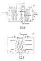
- FIG. 4is a schematic of a drum heat exchanger
- FIG. 5is a schematic of a once-through counter flow heat exchanger.
- the combined cycle plant 10in one embodiment has a gas turbine 12 that receives air 50 and fuel 14 and produces a rotation force to a shaft 16 to drive an electric generator 18 .
- the gas turbine 12creates an exhaust gas 20 .
- the exhaust gas 20is at a flow of 2,367,000 lbs/hour at a temperature of 1000° F.
- the exhaust gas 20is used to heat a heat exchange fluid 21 in a heat recovery steam generator 22 .
- the heat exchange fluid 21is water.
- the water in a liquid state 24is sent to the heat recovery steam generator 22 from a water supply 26 .
- the water in the liquid state 24 prior to the heat recovery steam generator 22is treated to remove dissolved minerals from the water, such as iron, calcium, and silicon.
- the water supply 26can include a de-mineralization system, an acid/caustic system or other systems to treat the water.
- the combined cycle plant 10has a pump 28 to move the water 24 from the water supply 26 to the heat recovery steam generator 22 .
- the pump 28in addition pressurizes the heat recovery steam generator 22 .
- the liquid water 24 , the heat exchange fluid 21 ,is converted to water in gaseous state, steam 30 , in the heat recovery steam generator 22 .
- the steam 30is sent to a steam turbine 32 .
- the energy of the pressurized steamis extracted to rotate a shaft 34 .
- the shaft 34drives a second electric generator 36 . It is recognize that both the shaft 16 of the gas turbine 12 and the shaft 34 of the steam turbine 32 can drive a single electric generator.
- the exhaust gas 20 from the gas turbine 12 after passing through the heat recovery steam generator 22 and a steam exhaust 38 from the steam turbine 32are mixed to form an exhaust gas/steam mixture 40 .
- the exhaust gas/steam mixture 40is mixed and vented to atmosphere through an exhaust stack 42 .
- the gas turbine 12 of the combined cycle planthas a compressor 48 that compresses air 50 .
- the air 50 and the fuel 14are mixed in a combustion chamber 52 of the gas turbine 12 .
- the mixtureis ignited and burned to produce a hot working fluid 54 .
- the working fluid 54pushes a series of blades in a turbine 56 of the gas turbine 12 . This produces a rotational force that spins the compressor 48 in addition to rotating the shaft 16 connected to the electric generator 18 , as seen in FIG. 1, to produce electric power.
- a product of the combustion of the fuel and the air in the gas turbine 12is the hot exhaust gas 20 .
- the hot exhaust gas 20is directed from the gas turbine 12 through the heat recovery steam generator 22 that is described in greater detail in FIGS. 4 and 5.
- the steam turbine 32 of the combined cycle plant 10is shown.
- the steam turbine 32is an open cycle system in that the exhaust steam 38 is vented to atmosphere. This is in contrast to a closed cycle in which the dynamic fluid does not enter or leave the system but is used over and over again such as in a closed cycle steam turbine.
- the exhaust steamis captured and returned to the heat recovery steam generator 22 . This increases the complexity, cost and maintainability because of the addition of steam condenser, circulating water system, condensate water system, and a large cooling tower to reject the low energy heat.
- the steam turbine 32has a turbine 60 .
- the turbinereceives the steam 30 from the heat recovery steam generator 22 and rotates the series of blades in the turbine 60 to rotate the shaft 34 connected to the electric generator 36 to produce electric power.
- the steam exhaust 38is sent to the exhaust stack 42 to mix with the exhaust gas 20 .
- the heat of the exhaust gas 20is transferred to water to produce steam.
- the water to the heat recovery steam generator 22is provided by the water supply 26 .
- the water 24is pumped to the heat recovery steam generator 22 by the pump 28 , which in a preferred embodiment is an electric driven centrifugal pump.
- the exhaust gas 20 from the gas turbine 12passes around a plurality of tubes carrying the water 24 to convert the water to steam.
- a drum heat recovery steam generator 64is shown.
- the drum generator 64has an economizer 65 that receives water in a liquid state 24 from the water supply 26 .
- the exhaust gas 20passes over the tubes of the economizer 65 .
- the water 24 that passes through the economizer 65is preheated to near the saturation temperature prior to being feed into the steam generator drum 68 .
- Water 24flows down from the steam generator drum 68 in at least one down feed tube 69 to a blow-down drum 66 and then flows up through a plurality of steam generating tubes 70 to the steam generator drum 68 by natural circulation.
- the exhaust gas 20passes over the tubes 70 to change the pressurized water 24 into a saturated steam 30 .
- the steam 30passes from the steam generator drum 68 through a plurality of superheater tubes 72 to raise the temperature of the steam 30 above the saturation temperature.
- the super heated steam 30is sent to the open cycle steam turbine 32 .
- FIG. 5shows a section of an alternative heat recovery steam generator 22 .
- the generator 22is a once-through exchanger 76 .
- the exchanger 76has a plurality of tubes 78 for the heat exchange fluid 21 , water 24 .
- the exhaust gas 20flows in one direction and the heat exchange fluid 21 flows in the other.
- the heat exchange fluid 21 , water 24changes to steam 30 as it absorbs heat energy from the exhaust gas 20 in the heat recovery steam generator 22 .
- different segments of the tubes 78act as the economizer, evaporator and superheater.
- the watergenerally needs to be of a better quality in the once-through exchanger 76 then in the drum generator 64 .
- the drum generator 64has blow-down capability to clean impurities, which is not possible in the once-through exchanger 76 .
- heat recovery steam generators 22While two styles of the heat recovery steam generators 22 are shown, it is recognized that other style heat exchangers or heat recovery steam generators can be used.
- other styles of the heat recovery steam generators 22include force circulation steam generators or kettle boilers.
- the exhaust steam 38 from the steam turbine 32is released at atmospheric pressure to the exhaust stack 42 as seen in FIG. 1 .
- the exhaust gas 20 from the gas turbine 12 after passing through the heat recovery steam generator 22 to produce the steamexits from the heat recovery steam generator 22 to the exhaust stack 42 .
- the steam turbine 32 and the heat recovery steam generator 22need to be sized relative to the gas turbine 12 of the combined cycle plant 10 in order to operate efficiently.
- the gas turbine 12typically operates at its base rating
- the plant designerknows the power rating of the turbine and its exhaust gas flow rate and temperature.
- the designercan take the exhaust gas flow temperature and rate to determine what size heat recovery steam generator 22 is needed and how much steam can be produced at a certain pressure, such as 700 PSI at a desired flow rate.
- the designer with the known flow rate and temperature and pressure of the steam generated by the heat recovery steam generator 22can size the steam turbine 32 to efficiently convert this energy into rotational energy to drive the electric generator 36 of FIG. 1 .
- this dual open cycle systemsimplifies that power plant design from the prior art and reduces maintenance and installation cost. In addition, it improves the reliability of the power plant over the previous combined cycle plants.
Landscapes
- Engineering & Computer Science (AREA)
- Chemical & Material Sciences (AREA)
- Combustion & Propulsion (AREA)
- Mechanical Engineering (AREA)
- General Engineering & Computer Science (AREA)
- Physics & Mathematics (AREA)
- Life Sciences & Earth Sciences (AREA)
- High Energy & Nuclear Physics (AREA)
- Sustainable Development (AREA)
- Sustainable Energy (AREA)
- Engine Equipment That Uses Special Cycles (AREA)
Abstract
Description
Claims (17)
Priority Applications (1)
| Application Number | Priority Date | Filing Date | Title |
|---|---|---|---|
| US10/055,802US6715294B2 (en) | 2001-01-24 | 2002-01-23 | Combined open cycle system for thermal energy conversion |
Applications Claiming Priority (2)
| Application Number | Priority Date | Filing Date | Title |
|---|---|---|---|
| US26393601P | 2001-01-24 | 2001-01-24 | |
| US10/055,802US6715294B2 (en) | 2001-01-24 | 2002-01-23 | Combined open cycle system for thermal energy conversion |
Publications (2)
| Publication Number | Publication Date |
|---|---|
| US20020116930A1 US20020116930A1 (en) | 2002-08-29 |
| US6715294B2true US6715294B2 (en) | 2004-04-06 |
Family
ID=26734634
Family Applications (1)
| Application Number | Title | Priority Date | Filing Date |
|---|---|---|---|
| US10/055,802Expired - LifetimeUS6715294B2 (en) | 2001-01-24 | 2002-01-23 | Combined open cycle system for thermal energy conversion |
Country Status (1)
| Country | Link |
|---|---|
| US (1) | US6715294B2 (en) |
Cited By (24)
| Publication number | Priority date | Publication date | Assignee | Title |
|---|---|---|---|---|
| US20030182944A1 (en)* | 2002-04-02 | 2003-10-02 | Hoffman John S. | Highly supercharged gas-turbine generating system |
| WO2010121255A1 (en)* | 2009-04-17 | 2010-10-21 | Echogen Power Systems | System and method for managing thermal issues in gas turbine engines |
| US20110185729A1 (en)* | 2009-09-17 | 2011-08-04 | Held Timothy J | Thermal energy conversion device |
| US8613195B2 (en) | 2009-09-17 | 2013-12-24 | Echogen Power Systems, Llc | Heat engine and heat to electricity systems and methods with working fluid mass management control |
| US8616001B2 (en) | 2010-11-29 | 2013-12-31 | Echogen Power Systems, Llc | Driven starter pump and start sequence |
| US8616323B1 (en) | 2009-03-11 | 2013-12-31 | Echogen Power Systems | Hybrid power systems |
| US8783034B2 (en) | 2011-11-07 | 2014-07-22 | Echogen Power Systems, Llc | Hot day cycle |
| US8813497B2 (en) | 2009-09-17 | 2014-08-26 | Echogen Power Systems, Llc | Automated mass management control |
| US8857186B2 (en) | 2010-11-29 | 2014-10-14 | Echogen Power Systems, L.L.C. | Heat engine cycles for high ambient conditions |
| US8869531B2 (en) | 2009-09-17 | 2014-10-28 | Echogen Power Systems, Llc | Heat engines with cascade cycles |
| US9062898B2 (en) | 2011-10-03 | 2015-06-23 | Echogen Power Systems, Llc | Carbon dioxide refrigeration cycle |
| US9091278B2 (en) | 2012-08-20 | 2015-07-28 | Echogen Power Systems, Llc | Supercritical working fluid circuit with a turbo pump and a start pump in series configuration |
| US9118226B2 (en) | 2012-10-12 | 2015-08-25 | Echogen Power Systems, Llc | Heat engine system with a supercritical working fluid and processes thereof |
| US9316404B2 (en) | 2009-08-04 | 2016-04-19 | Echogen Power Systems, Llc | Heat pump with integral solar collector |
| US9341084B2 (en) | 2012-10-12 | 2016-05-17 | Echogen Power Systems, Llc | Supercritical carbon dioxide power cycle for waste heat recovery |
| US9441504B2 (en) | 2009-06-22 | 2016-09-13 | Echogen Power Systems, Llc | System and method for managing thermal issues in one or more industrial processes |
| US9638065B2 (en) | 2013-01-28 | 2017-05-02 | Echogen Power Systems, Llc | Methods for reducing wear on components of a heat engine system at startup |
| US9752460B2 (en) | 2013-01-28 | 2017-09-05 | Echogen Power Systems, Llc | Process for controlling a power turbine throttle valve during a supercritical carbon dioxide rankine cycle |
| US10934895B2 (en) | 2013-03-04 | 2021-03-02 | Echogen Power Systems, Llc | Heat engine systems with high net power supercritical carbon dioxide circuits |
| US11187112B2 (en) | 2018-06-27 | 2021-11-30 | Echogen Power Systems Llc | Systems and methods for generating electricity via a pumped thermal energy storage system |
| US11293309B2 (en) | 2014-11-03 | 2022-04-05 | Echogen Power Systems, Llc | Active thrust management of a turbopump within a supercritical working fluid circuit in a heat engine system |
| US11435120B2 (en) | 2020-05-05 | 2022-09-06 | Echogen Power Systems (Delaware), Inc. | Split expansion heat pump cycle |
| US11629638B2 (en) | 2020-12-09 | 2023-04-18 | Supercritical Storage Company, Inc. | Three reservoir electric thermal energy storage system |
| US12331664B2 (en) | 2023-02-07 | 2025-06-17 | Supercritical Storage Company, Inc. | Waste heat integration into pumped thermal energy storage |
Families Citing this family (7)
| Publication number | Priority date | Publication date | Assignee | Title |
|---|---|---|---|---|
| US6931860B2 (en)* | 2002-11-18 | 2005-08-23 | Gregory B. Ryan | System and method for water pasteurization and power generation |
| US8763404B2 (en) | 2008-12-31 | 2014-07-01 | Rolls-Royce Corporation | Systems, apparatuses, and methods of harnessing thermal energy of gas turbine engines |
| US8943836B2 (en)* | 2009-07-10 | 2015-02-03 | Nrg Energy, Inc. | Combined cycle power plant |
| US9416685B2 (en)* | 2014-01-06 | 2016-08-16 | Siemens Energy, Inc. | Auxillary steam generation arrangement for a combined cycle power plant |
| GR20170100159A (en)* | 2017-04-05 | 2019-01-25 | Αργυριος Βασιλειου Μπενος | Thermal energy-recycling pump |
| US10914199B2 (en)* | 2018-06-25 | 2021-02-09 | General Electric Company | Piping layout for water steam cycle system of combined cycle power plant |
| US12320293B1 (en)* | 2023-11-21 | 2025-06-03 | General Electric Company | Turbine engine including a steam system |
Citations (29)
| Publication number | Priority date | Publication date | Assignee | Title |
|---|---|---|---|---|
| US2652034A (en)* | 1949-06-04 | 1953-09-15 | Baillot Helene | Compound steam locomotive |
| US3087304A (en) | 1958-12-22 | 1963-04-30 | Walter Hellmuth | Method and device for propelling submarine vehicles |
| US3232052A (en)* | 1962-12-28 | 1966-02-01 | Creusot Forges Ateliers | Power producing installation comprising a steam turbine and at least one gas turbine |
| US3359723A (en)* | 1965-10-29 | 1967-12-26 | Exxon Research Engineering Co | Method of combusting a residual fuel utilizing a two-stage air injection technique and an intermediate steam injection step |
| US3422800A (en)* | 1967-06-19 | 1969-01-21 | Gen Electric | Combined gas turbine and waste heat boiler control system |
| US4366674A (en)* | 1980-06-06 | 1983-01-04 | Caterpillar Tractor Co. | Internal combustion engine with Rankine bottoming cycle |
| US4479355A (en)* | 1983-02-25 | 1984-10-30 | Exxon Research & Engineering Co. | Power plant integrating coal-fired steam boiler with air turbine |
| US4660376A (en) | 1984-04-27 | 1987-04-28 | General Electric Company | Method for operating a fluid injection gas turbine engine |
| US4785621A (en) | 1987-05-28 | 1988-11-22 | General Electric Company | Air bottoming cycle for coal gasification plant |
| US4854121A (en) | 1986-10-09 | 1989-08-08 | Kabushiki Kaisha Toshiba | Combined cycle power plant capable of controlling water level in boiler drum of power plant |
| US4896499A (en)* | 1978-10-26 | 1990-01-30 | Rice Ivan G | Compression intercooled gas turbine combined cycle |
| US5170622A (en) | 1991-04-02 | 1992-12-15 | Cheng Dah Y | Advanced regenerative parallel compound dual fluid heat engine Advanced Cheng Cycle (ACC) |
| US5271215A (en) | 1991-03-18 | 1993-12-21 | Gaz De France | Natural gas stream turbine system operating with a semi-open cycle |
| US5428950A (en) | 1993-11-04 | 1995-07-04 | General Electric Co. | Steam cycle for combined cycle with steam cooled gas turbine |
| US5442908A (en) | 1993-01-25 | 1995-08-22 | Westinghouse Electric Corporation | Combined combustion and steam turbine power plant |
| US5595059A (en)* | 1995-03-02 | 1997-01-21 | Westingthouse Electric Corporation | Combined cycle power plant with thermochemical recuperation and flue gas recirculation |
| US5632143A (en)* | 1994-06-14 | 1997-05-27 | Ormat Industries Ltd. | Gas turbine system and method using temperature control of the exhaust gas entering the heat recovery cycle by mixing with ambient air |
| US5664414A (en)* | 1995-08-31 | 1997-09-09 | Ormat Industries Ltd. | Method of and apparatus for generating power |
| US5813215A (en) | 1995-02-21 | 1998-09-29 | Weisser; Arthur M. | Combined cycle waste heat recovery system |
| WO1999037901A1 (en) | 1996-07-24 | 1999-07-29 | Mitsubishi Heavy Industries, Ltd. | Combined cycle electric power plant |
| US5970714A (en)* | 1992-10-02 | 1999-10-26 | Ormat Industries Ltd. | Geothermal power plant operating on high pressure geothermal fluid |
| US6109020A (en)* | 1997-07-28 | 2000-08-29 | Asea Brown Boveri Ag | Combined cycle power plant with a once through steam generator |
| US6173679B1 (en)* | 1997-06-30 | 2001-01-16 | Siemens Aktiengesellschaft | Waste-heat steam generator |
| US6230480B1 (en)* | 1998-08-31 | 2001-05-15 | Rollins, Iii William Scott | High power density combined cycle power plant |
| US6237542B1 (en) | 1999-01-29 | 2001-05-29 | Kabushiki Kaisha Toshiba | Heat recovery boiler and hot banking releasing method thereof |
| US6279311B1 (en) | 1998-01-23 | 2001-08-28 | Mitsubishi Heavy Industries, Ltd. | Combined cycle power plant |
| US6311474B2 (en) | 1996-07-24 | 2001-11-06 | Mitsubishi Heavy Industries, Ltd. | Combined cycle electric power plant |
| US6332321B1 (en) | 1992-11-09 | 2001-12-25 | Ormat Industries Ltd. | Apparatus for augmenting power produced from gas turbines |
| US20020100271A1 (en)* | 2000-05-12 | 2002-08-01 | Fermin Viteri | Semi-closed brayton cycle gas turbine power systems |
- 2002
- 2002-01-23USUS10/055,802patent/US6715294B2/ennot_activeExpired - Lifetime
Patent Citations (31)
| Publication number | Priority date | Publication date | Assignee | Title |
|---|---|---|---|---|
| US2652034A (en)* | 1949-06-04 | 1953-09-15 | Baillot Helene | Compound steam locomotive |
| US3087304A (en) | 1958-12-22 | 1963-04-30 | Walter Hellmuth | Method and device for propelling submarine vehicles |
| US3232052A (en)* | 1962-12-28 | 1966-02-01 | Creusot Forges Ateliers | Power producing installation comprising a steam turbine and at least one gas turbine |
| US3359723A (en)* | 1965-10-29 | 1967-12-26 | Exxon Research Engineering Co | Method of combusting a residual fuel utilizing a two-stage air injection technique and an intermediate steam injection step |
| US3422800A (en)* | 1967-06-19 | 1969-01-21 | Gen Electric | Combined gas turbine and waste heat boiler control system |
| US4896499A (en)* | 1978-10-26 | 1990-01-30 | Rice Ivan G | Compression intercooled gas turbine combined cycle |
| US4896499B1 (en)* | 1978-10-26 | 1992-09-15 | G Rice Ivan | |
| US4366674A (en)* | 1980-06-06 | 1983-01-04 | Caterpillar Tractor Co. | Internal combustion engine with Rankine bottoming cycle |
| US4479355A (en)* | 1983-02-25 | 1984-10-30 | Exxon Research & Engineering Co. | Power plant integrating coal-fired steam boiler with air turbine |
| US4660376A (en) | 1984-04-27 | 1987-04-28 | General Electric Company | Method for operating a fluid injection gas turbine engine |
| US4854121A (en) | 1986-10-09 | 1989-08-08 | Kabushiki Kaisha Toshiba | Combined cycle power plant capable of controlling water level in boiler drum of power plant |
| US4785621A (en) | 1987-05-28 | 1988-11-22 | General Electric Company | Air bottoming cycle for coal gasification plant |
| US5271215A (en) | 1991-03-18 | 1993-12-21 | Gaz De France | Natural gas stream turbine system operating with a semi-open cycle |
| US5170622A (en) | 1991-04-02 | 1992-12-15 | Cheng Dah Y | Advanced regenerative parallel compound dual fluid heat engine Advanced Cheng Cycle (ACC) |
| US5970714A (en)* | 1992-10-02 | 1999-10-26 | Ormat Industries Ltd. | Geothermal power plant operating on high pressure geothermal fluid |
| US6332321B1 (en) | 1992-11-09 | 2001-12-25 | Ormat Industries Ltd. | Apparatus for augmenting power produced from gas turbines |
| US5442908A (en) | 1993-01-25 | 1995-08-22 | Westinghouse Electric Corporation | Combined combustion and steam turbine power plant |
| US5428950A (en) | 1993-11-04 | 1995-07-04 | General Electric Co. | Steam cycle for combined cycle with steam cooled gas turbine |
| US5632143A (en)* | 1994-06-14 | 1997-05-27 | Ormat Industries Ltd. | Gas turbine system and method using temperature control of the exhaust gas entering the heat recovery cycle by mixing with ambient air |
| US5813215A (en) | 1995-02-21 | 1998-09-29 | Weisser; Arthur M. | Combined cycle waste heat recovery system |
| US5595059A (en)* | 1995-03-02 | 1997-01-21 | Westingthouse Electric Corporation | Combined cycle power plant with thermochemical recuperation and flue gas recirculation |
| US5664414A (en)* | 1995-08-31 | 1997-09-09 | Ormat Industries Ltd. | Method of and apparatus for generating power |
| US6311474B2 (en) | 1996-07-24 | 2001-11-06 | Mitsubishi Heavy Industries, Ltd. | Combined cycle electric power plant |
| WO1999037901A1 (en) | 1996-07-24 | 1999-07-29 | Mitsubishi Heavy Industries, Ltd. | Combined cycle electric power plant |
| US6173679B1 (en)* | 1997-06-30 | 2001-01-16 | Siemens Aktiengesellschaft | Waste-heat steam generator |
| US6109020A (en)* | 1997-07-28 | 2000-08-29 | Asea Brown Boveri Ag | Combined cycle power plant with a once through steam generator |
| US6279311B1 (en) | 1998-01-23 | 2001-08-28 | Mitsubishi Heavy Industries, Ltd. | Combined cycle power plant |
| US20010023576A1 (en) | 1998-08-31 | 2001-09-27 | Rollins William S. | High density combined cycle power plant process |
| US6230480B1 (en)* | 1998-08-31 | 2001-05-15 | Rollins, Iii William Scott | High power density combined cycle power plant |
| US6237542B1 (en) | 1999-01-29 | 2001-05-29 | Kabushiki Kaisha Toshiba | Heat recovery boiler and hot banking releasing method thereof |
| US20020100271A1 (en)* | 2000-05-12 | 2002-08-01 | Fermin Viteri | Semi-closed brayton cycle gas turbine power systems |
Non-Patent Citations (1)
| Title |
|---|
| William & Larson, May 1988, World Bank, Princeton University, 12 pages.* |
Cited By (31)
| Publication number | Priority date | Publication date | Assignee | Title |
|---|---|---|---|---|
| US20030182944A1 (en)* | 2002-04-02 | 2003-10-02 | Hoffman John S. | Highly supercharged gas-turbine generating system |
| US8616323B1 (en) | 2009-03-11 | 2013-12-31 | Echogen Power Systems | Hybrid power systems |
| US9014791B2 (en) | 2009-04-17 | 2015-04-21 | Echogen Power Systems, Llc | System and method for managing thermal issues in gas turbine engines |
| WO2010121255A1 (en)* | 2009-04-17 | 2010-10-21 | Echogen Power Systems | System and method for managing thermal issues in gas turbine engines |
| US9441504B2 (en) | 2009-06-22 | 2016-09-13 | Echogen Power Systems, Llc | System and method for managing thermal issues in one or more industrial processes |
| US9316404B2 (en) | 2009-08-04 | 2016-04-19 | Echogen Power Systems, Llc | Heat pump with integral solar collector |
| US9458738B2 (en) | 2009-09-17 | 2016-10-04 | Echogen Power Systems, Llc | Heat engine and heat to electricity systems and methods with working fluid mass management control |
| US8813497B2 (en) | 2009-09-17 | 2014-08-26 | Echogen Power Systems, Llc | Automated mass management control |
| US8869531B2 (en) | 2009-09-17 | 2014-10-28 | Echogen Power Systems, Llc | Heat engines with cascade cycles |
| US8966901B2 (en) | 2009-09-17 | 2015-03-03 | Dresser-Rand Company | Heat engine and heat to electricity systems and methods for working fluid fill system |
| US9863282B2 (en) | 2009-09-17 | 2018-01-09 | Echogen Power System, LLC | Automated mass management control |
| US8794002B2 (en) | 2009-09-17 | 2014-08-05 | Echogen Power Systems | Thermal energy conversion method |
| US20110185729A1 (en)* | 2009-09-17 | 2011-08-04 | Held Timothy J | Thermal energy conversion device |
| US8613195B2 (en) | 2009-09-17 | 2013-12-24 | Echogen Power Systems, Llc | Heat engine and heat to electricity systems and methods with working fluid mass management control |
| US9115605B2 (en) | 2009-09-17 | 2015-08-25 | Echogen Power Systems, Llc | Thermal energy conversion device |
| US9410449B2 (en) | 2010-11-29 | 2016-08-09 | Echogen Power Systems, Llc | Driven starter pump and start sequence |
| US8857186B2 (en) | 2010-11-29 | 2014-10-14 | Echogen Power Systems, L.L.C. | Heat engine cycles for high ambient conditions |
| US8616001B2 (en) | 2010-11-29 | 2013-12-31 | Echogen Power Systems, Llc | Driven starter pump and start sequence |
| US9062898B2 (en) | 2011-10-03 | 2015-06-23 | Echogen Power Systems, Llc | Carbon dioxide refrigeration cycle |
| US8783034B2 (en) | 2011-11-07 | 2014-07-22 | Echogen Power Systems, Llc | Hot day cycle |
| US9091278B2 (en) | 2012-08-20 | 2015-07-28 | Echogen Power Systems, Llc | Supercritical working fluid circuit with a turbo pump and a start pump in series configuration |
| US9341084B2 (en) | 2012-10-12 | 2016-05-17 | Echogen Power Systems, Llc | Supercritical carbon dioxide power cycle for waste heat recovery |
| US9118226B2 (en) | 2012-10-12 | 2015-08-25 | Echogen Power Systems, Llc | Heat engine system with a supercritical working fluid and processes thereof |
| US9638065B2 (en) | 2013-01-28 | 2017-05-02 | Echogen Power Systems, Llc | Methods for reducing wear on components of a heat engine system at startup |
| US9752460B2 (en) | 2013-01-28 | 2017-09-05 | Echogen Power Systems, Llc | Process for controlling a power turbine throttle valve during a supercritical carbon dioxide rankine cycle |
| US10934895B2 (en) | 2013-03-04 | 2021-03-02 | Echogen Power Systems, Llc | Heat engine systems with high net power supercritical carbon dioxide circuits |
| US11293309B2 (en) | 2014-11-03 | 2022-04-05 | Echogen Power Systems, Llc | Active thrust management of a turbopump within a supercritical working fluid circuit in a heat engine system |
| US11187112B2 (en) | 2018-06-27 | 2021-11-30 | Echogen Power Systems Llc | Systems and methods for generating electricity via a pumped thermal energy storage system |
| US11435120B2 (en) | 2020-05-05 | 2022-09-06 | Echogen Power Systems (Delaware), Inc. | Split expansion heat pump cycle |
| US11629638B2 (en) | 2020-12-09 | 2023-04-18 | Supercritical Storage Company, Inc. | Three reservoir electric thermal energy storage system |
| US12331664B2 (en) | 2023-02-07 | 2025-06-17 | Supercritical Storage Company, Inc. | Waste heat integration into pumped thermal energy storage |
Also Published As
| Publication number | Publication date |
|---|---|
| US20020116930A1 (en) | 2002-08-29 |
Similar Documents
| Publication | Publication Date | Title |
|---|---|---|
| US6715294B2 (en) | Combined open cycle system for thermal energy conversion | |
| EP0676532B1 (en) | Steam injected gas turbine system with topping steam turbine | |
| JP3681434B2 (en) | Cogeneration system and combined cycle power generation system | |
| RU2009333C1 (en) | Combined steam-gas power plant and method of its operation | |
| KR101320593B1 (en) | Cogeneration system using heat pump | |
| CA2263036C (en) | Gas turbine combined cycle | |
| US20190323384A1 (en) | Boilor plant and method for operating the same | |
| EP1103699A3 (en) | Gas turbine combined cycle system | |
| US4702081A (en) | Combined steam and gas turbine plant | |
| EP2132415A2 (en) | Arrangement with a steam turbine and a condenser for feedwater preheating | |
| RU2335641C2 (en) | Method of enhancing efficiency and output of two-loop nuclear power station | |
| RU2230921C2 (en) | Method of operation and steam-gas plant of power station operating on combination fuel (solid and gaseous or liquid fuel) | |
| RU2001132885A (en) | The method of operation of a combined cycle gas-fired power plant (solid with gaseous or liquid, or nuclear with gaseous or liquid) and a combined-cycle plant for its implementation | |
| JP4185326B2 (en) | Gas / air combined turbine equipment | |
| RU2003102313A (en) | METHOD FOR OPERATING ATOMIC STEAM TURBINE INSTALLATION AND INSTALLATION FOR ITS IMPLEMENTATION | |
| RU2326246C1 (en) | Ccpp plant for combined heat and power production | |
| KR20190069994A (en) | Power plant sysyem combined with gas turbine | |
| RU2139430C1 (en) | Combined-cycle plant | |
| KR20220149996A (en) | Combined cycle power generation system | |
| RU94027713A (en) | Economically efficient thermal power station and its operation | |
| RU2773410C1 (en) | Combined cycle gas plant | |
| WO2002014664A1 (en) | Gas turbine engine having improved efficiency | |
| Jericha et al. | Combined cycle enhancement | |
| US20020189262A1 (en) | Method for operating a steam turbine , and a turbine system provided with a steam turbine that functions according to said method | |
| Tawney et al. | Economic and performance evaluation of combined cycle repowering options |
Legal Events
| Date | Code | Title | Description |
|---|---|---|---|
| AS | Assignment | Owner name:POWER TECHNOLOGY, INCORPORATED, MASSACHUSETTS Free format text:ASSIGNMENT OF ASSIGNORS INTEREST;ASSIGNOR:ANDERSON, RODGER O.;REEL/FRAME:013629/0151 Effective date:20021218 | |
| AS | Assignment | Owner name:WACHOVIA BANK, NATIONAL ASSOCIATION, NORTH CAROLIN Free format text:SECURITY INTEREST;ASSIGNOR:DRS POWER TECHNOLOGY, INC.;REEL/FRAME:013653/0687 Effective date:20030331 | |
| AS | Assignment | Owner name:DRS POWER TECHNOLOGY, INC., NEW JERSEY Free format text:MERGER;ASSIGNOR:POWER TECHNOLOGY INCORPORATED;REEL/FRAME:014563/0775 Effective date:20030318 | |
| FEPP | Fee payment procedure | Free format text:PAYER NUMBER DE-ASSIGNED (ORIGINAL EVENT CODE: RMPN); ENTITY STATUS OF PATENT OWNER: LARGE ENTITY Free format text:PAYOR NUMBER ASSIGNED (ORIGINAL EVENT CODE: ASPN); ENTITY STATUS OF PATENT OWNER: LARGE ENTITY | |
| STCF | Information on status: patent grant | Free format text:PATENTED CASE | |
| CC | Certificate of correction | ||
| AS | Assignment | Owner name:WACHOVIA BANK, NATIONAL ASSOCIATION, NORTH CAROLIN Free format text:PATENT SECURITY AGREEMENT;ASSIGNOR:DRS POWER TECHNOLOGY, INC.;REEL/FRAME:017286/0367 Effective date:20060131 | |
| AS | Assignment | Owner name:WACHOVIA BANK, NATIONAL ASSOCIATION, NORTH CAROLIN Free format text:PATENT SECURITY AGREEMENT;ASSIGNOR:DRS POWER TECHNOLOGY, INC.;REEL/FRAME:019573/0743 Effective date:20060615 | |
| FPAY | Fee payment | Year of fee payment:4 | |
| AS | Assignment | Owner name:DRS POWER TECHNOLOGY, INC.,NEW JERSEY Free format text:RELEASE BY SECURED PARTY;ASSIGNOR:WELLS FARGO BANK, N.A.;REEL/FRAME:024576/0273 Effective date:20100607 Owner name:DRS POWER TECHNOLOGY, INC.,NEW JERSEY Free format text:RELEASE BY SECURED PARTY;ASSIGNOR:WELLS FARGO BANK, N.A.;REEL/FRAME:024576/0324 Effective date:20100607 | |
| AS | Assignment | Owner name:DRS POWER TECHNOLOGY, INC.,MASSACHUSETTS Free format text:RELEASE BY SECURED PARTY;ASSIGNOR:WELLS FARGO BANK, N.A.;REEL/FRAME:024599/0600 Effective date:20100607 | |
| FPAY | Fee payment | Year of fee payment:8 | |
| FPAY | Fee payment | Year of fee payment:12 | |
| AS | Assignment | Owner name:DRS NAVAL POWER SYSTEMS, INC., WISCONSIN Free format text:MERGER;ASSIGNOR:DRS POWER TECHNOLOGY, INC.;REEL/FRAME:053852/0756 Effective date:20191226 |