US6715007B1 - Method of regulating a flow of data in a communication system and apparatus therefor - Google Patents
Method of regulating a flow of data in a communication system and apparatus thereforDownload PDFInfo
- Publication number
- US6715007B1 US6715007B1US09/615,303US61530300AUS6715007B1US 6715007 B1US6715007 B1US 6715007B1US 61530300 AUS61530300 AUS 61530300AUS 6715007 B1US6715007 B1US 6715007B1
- Authority
- US
- United States
- Prior art keywords
- data
- rate
- buffer
- level
- source
- Prior art date
- Legal status (The legal status is an assumption and is not a legal conclusion. Google has not performed a legal analysis and makes no representation as to the accuracy of the status listed.)
- Expired - Fee Related, expires
Links
Images


Classifications
- H—ELECTRICITY
- H04—ELECTRIC COMMUNICATION TECHNIQUE
- H04L—TRANSMISSION OF DIGITAL INFORMATION, e.g. TELEGRAPHIC COMMUNICATION
- H04L47/00—Traffic control in data switching networks
- H04L47/10—Flow control; Congestion control
- H04L47/30—Flow control; Congestion control in combination with information about buffer occupancy at either end or at transit nodes
- H—ELECTRICITY
- H04—ELECTRIC COMMUNICATION TECHNIQUE
- H04L—TRANSMISSION OF DIGITAL INFORMATION, e.g. TELEGRAPHIC COMMUNICATION
- H04L47/00—Traffic control in data switching networks
- H04L47/10—Flow control; Congestion control
- H—ELECTRICITY
- H04—ELECTRIC COMMUNICATION TECHNIQUE
- H04L—TRANSMISSION OF DIGITAL INFORMATION, e.g. TELEGRAPHIC COMMUNICATION
- H04L47/00—Traffic control in data switching networks
- H04L47/10—Flow control; Congestion control
- H04L47/26—Flow control; Congestion control using explicit feedback to the source, e.g. choke packets
- H04L47/263—Rate modification at the source after receiving feedback
- H—ELECTRICITY
- H04—ELECTRIC COMMUNICATION TECHNIQUE
- H04L—TRANSMISSION OF DIGITAL INFORMATION, e.g. TELEGRAPHIC COMMUNICATION
- H04L47/00—Traffic control in data switching networks
- H04L47/10—Flow control; Congestion control
- H04L47/33—Flow control; Congestion control using forward notification
- Y—GENERAL TAGGING OF NEW TECHNOLOGICAL DEVELOPMENTS; GENERAL TAGGING OF CROSS-SECTIONAL TECHNOLOGIES SPANNING OVER SEVERAL SECTIONS OF THE IPC; TECHNICAL SUBJECTS COVERED BY FORMER USPC CROSS-REFERENCE ART COLLECTIONS [XRACs] AND DIGESTS
- Y02—TECHNOLOGIES OR APPLICATIONS FOR MITIGATION OR ADAPTATION AGAINST CLIMATE CHANGE
- Y02D—CLIMATE CHANGE MITIGATION TECHNOLOGIES IN INFORMATION AND COMMUNICATION TECHNOLOGIES [ICT], I.E. INFORMATION AND COMMUNICATION TECHNOLOGIES AIMING AT THE REDUCTION OF THEIR OWN ENERGY USE
- Y02D30/00—Reducing energy consumption in communication networks
- Y02D30/50—Reducing energy consumption in communication networks in wire-line communication networks, e.g. low power modes or reduced link rate
Definitions
- the present inventionrelates to the field of communication systems. More specifically, the present invention relates to the field of data-flow regulation in communication systems.
- serial datais transmitted and received at identical data rates. That is, a data-rate clock in a data source would be identical to a data-rate clock in a data sink, e.g., 9600. ⁇ overscore (0000) ⁇ baud. To do so, however, would require perfectly matched oscillators in both the data source and sink. This is not practical in a real-world system. Crystal tolerances alone would prohibit such exactitude.
- data source and data sink oscillatorscan become very close in frequency. Close, however, is not exact, and this inexactitude causes problems, especially with substantially continuous data. For example, it may be seen that continuous-data rates of 9600.0001 baud and 9599.9999 baud for the source and sink, respectively, will eventually produce a data overrun. Similarly, continuous-data rates of 9599.9999 baud and 9600.0001 baud for the source and sink, respectively, will eventually produce a data underrun. Both overrun and underrun conditions produce errors in the data stream, and are therefore highly undesirable.
- a typical hardware correctionutilizes clock lines to synchronize the data rate clocks in both the data source and the data sink.
- a FIFO bufferis used to synchronize input and output data rates. This is typically done by interrupting the input data flow (when the input data rate is greater than the output data rate) or the output data flow (when the output data rate is greater than the input data rate) to compensate for rate differences. This produces discontinuous data, which itself may produce overrun or underrun conditions. Such discontinuous data also inhibits proper operation of the data source and/or data sink when continuous data is produced or expected.
- Such a methodshould be capable of compensating for mismatches between the source data rate and the sink data rate. Also, such a method should be capable of easily compensating for variations in data arrival times. Additionally, such a method should prevent data overrun and underrun conditions when the data is continuous over long periods of time.
- FIG. 1shows a block diagram depicting a communication system incorporating a data-rate regulator in accordance with a preferred embodiment of the present invention
- FIG. 2shows a schematic view depicting a data-rate regulation buffer with a diagram of buffer level over time in accordance with a preferred embodiment of the present invention
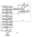
- FIG. 3shows a flow chart depicting a process to regulate a flow of data in the system depicted in FIG. 1 in accordance with a preferred embodiment of the present invention
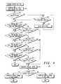
- FIG. 4shows a flow chart depicting a subprocess to control a buffer fill rate for the process of FIG. 3 in accordance with a preferred embodiment of the present invention
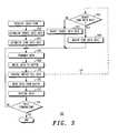
- FIG. 5shows a flow chart depicting a subprocess to establish a source data rate for the process of FIG. 3 in accordance with a preferred embodiment of the present invention.
- FIG. 6shows a flow chart depicting a subprocess to establish a sink data rate for the process of FIG. 3 in accordance with a preferred embodiment of the present invention.
- FIG. 1shows a block diagram depicting a software-defined communication system 20 incorporating a data-rate regulator 22 in accordance with a p referred embodiment of the present invention.
- system 20has a data source 24 configured to transmit data 26 at a source data rate (not shown).
- system 20has a data sink 28 configured to receive data 26 at a sink data rate (not shown). Due to the use of real-world components, the source data rate and the sink data rate are not precisely identical, e.g., 9600. ⁇ overscore (0000) ⁇ baud. Consequently, data-rate regulation and/or synchronization are performed to prevent overrun and underrun conditions.
- source and sink data ratesare derived from data-rate generators within data source 24 and data sink 28 .
- a typical data-rate generatorutilizes a crystal and a divider to obtain the desired data rate. Because of tolerances in crystals, it is not normally possible to obtain a data-source crystal and a data-sink crystal that are perfectly matched in frequency, as well as thermal, pressure, and other characteristics. Therefore, for the sake of discussion, if the source data rate of system 20 were to be exactly 9600 baud at a given instant, then the sink data rate at that instant, while within a tolerance of the data-sink crystal, is virtually guaranteed to not be exactly 9600 baud.
- data-rate regulator 22is inserted into system 20 between data source 24 and data sink 28 .
- Data 26is transmitted by data source 24 , received in data-rate regulator 22 by an input function 30 , and written into a buffer 32 at the source data rate.
- buffer 32is realized within a portion 36 of controller-readable memory.
- Input function 30 , output function 34 , and buffer memory portion 36are coupled to and under the control of a controller 38 .
- Controller 38is coupled to and under the control of a control program 40 realized within another portion 42 of controller-readable memory. It is control program 40 , acting through controller 38 , that controls and regulates the flow of data 26 between data source 24 and data sink 28 , i.e., through data-flow regulator 22 .
- FIG. 1depicts buffer memory portion 36 and/or control-program memory portion 42 as coupled to and/or a portion of a memory 44 within data sink 28 .
- This depictionrepresents a preferred embodiment where data-rate regulator 22 , while logically separate, is physically incorporated into data sink 28 , i.e., is located within a radio receiver of system 20 .
- buffer memory portion 36 and/or control-program memory portion 42may be portions of and share a common memory address space (not shown) with data sink memory 44 .
- FIG. 1depicts controller 38 as coupled to and a portion of a controller 46 within data sink 28 .
- This depictionrepresents a preferred embodiment where data-rate regulator 22 is physically incorporated into data sink 28 .
- regulator controller 38 and data-sink controller 46may be the same controller or processor, with control-program 40 serving as a routine within a greater control program (not shown) contained within data-sink memory 44 .
- FIG. 1is exemplary only. It is not a requirement of the present invention that data-rate regulator 22 be physically incorporated into data sink 28 . Under some circumstances, it may be more desirable to physically incorporate data-rate regulator 22 into data source 24 , or to physically have data-rate regulator 22 realized as an independent device.
- buffer memory portion 36 and/or control-program memory portion 42may be coupled to and/or a portion of a memory 48 within data source 24 .
- Buffer memory portion 36 and/or control-program memory portion 42may therefore be portions of and share a common memory address space (not shown) with data-source memory 48 .
- controller 38may be coupled to and a portion of a controller 50 within data source 24 .
- Regulator controller 38 and data-source controller 50may therefore be the same controller or processor, with control-program 40 serving as a routine within a greater control program (not shown) contained within data-source memory 48 .
- buffer memory portion 36 and/or control-program memory portion 42are portions of an independent memory 52 within data-rate regulator 22 .
- Buffer memory portion 36 and/or control-program memory portion 42share a common memory address space (not shown) addressable by controller 38 .
- Controller 38is an independent controller or processor within data-rate regulator 22 .
- FIG. 2shows a schematic view depicting buffer 32 with a data-flow diagram therefor in accordance with a preferred embodiment of the present invention.
- FIG. 3shows a flow chart depicting a process 100 to regulate a flow of data 26 in system 20 in accordance with a preferred embodiment of the present invention. The following discussion refers to FIGS. 1 through 3.
- a task 102establishes an initial value for the source data rate in data source 24 .
- a task 104establishes an initial value for the sink data rate.
- Tasks 102 and 104establish the source and sink data rates to a value greater than zero (the data rates always exist) and substantially equal to a predetermined data rate (not shown). For example, if the predetermined data rate is to be a theoretically perfect 9600 baud, then the source and sink data rates are set as close to this value as possible given the tolerances of the components involved.
- a transmitter (XMTR) 56(FIG.
- tasks 102 and 104are independent of each other and may be performed in either order. Likewise, it will be appreciated that, once tasks 102 and 104 establish the source and sink data rates, those data rates continue to be as established until altered by another task.
- Data 26is continuous.
- data source 24(FIG. 1) transmits data 26 at the source data rate.
- input function 30 of data-rate regulator 22receives data 26 and writes data 26 to buffer 32 , also at the source data rate. Since data 26 is continuous (after inception thereof), tasks 106 and 108 continuously transfer data 26 from data source 24 to buffer 32 at the source data rate without interruption. That is, even though the source data rate may inadvertently change due to variations in temperature, pressure, and other factors, or may intentionally be changed as discussed hereinafter, the source data rate is always substantially equal to the predetermined data rate and never nears zero.
- data 26may be packetized, i.e., as bursts of data interleaved with spaces.
- multiplexingmay be applied to allow the use of a plurality of data termini 60 (data sources 24 or data sinks 28 ), each having a terminus (source or sink) data rate (not shown).
- the data rateis typically much higher than the terminus data rate as defined herein.
- packetized datamay be considered to be continuous if the average terminus data rate of each data packet and its accompanying space is substantially equal to the terminus data rate and does not near zero.
- subprocess 116controls a buffer fill rate 54 .
- the operation of subprocess 116is discussed in detail hereinafter.
- output function 34 (FIG. 1) of data-rate regulator 22reads data 26 from buffer 32 and transmits data 26 to data sink 28 at the sink data rate.
- data sink 28receives data 26 , also at the sink data rate. Since, after inception, data 26 is continuous, tasks 110 and 112 continuously transfer data 26 from buffer 32 to data sink 28 at the sink data rate without interruption. That is, even though the sink data rate may inadvertently change due to variations in temperature, pressure, and other factors, or may intentionally be changed as discussed hereinafter, the sink data rate is always substantially equal to the predetermined data rate and never nears zero.
- a query task 114determines if an end of data 26 has been reached. If task 114 determines that a data termination condition exists, then controller 38 informs control program 40 so the next data 26 may be treated as initialization of data.
- task 114determines that data 26 is continuous, i.e. a data termination condition does not exist, then process 100 continues with tasks 106 , 108 , 116 , 110 , and 112 .
- tasks 106 , 108 , 116 , 110 , and 112are performed substantially simultaneously as long as data 26 is continuous and in a steady-state condition, i.e., between initialization and termination.
- FIG. 4shows a flow chart depicting subprocess 116 to control buffer fill rate 54 for process 100 in accordance with a preferred embodiment of the present invention. The following discussion refers to FIGS. 1 through 4.
- process 100executes subprocess 116 (FIGS. 3 and 4) to control buffer fill rate 54 .
- controller 38continuously monitors a buffer data level 62 , i.e., the amount of data 26 in buffer 32 from moment to moment, and buffer fill rate 54 , i.e., the rate at which data 26 is filling buffer 32 . Since buffer fill rate 54 is a rate of fill, buffer fill rate 54 is positive (i.e., the slope of buffer data level 62 in FIG. 2 extends from lower left to upper right) when buffer 32 is being filled. Likewise, buffer fill rate 54 is negative (i.e., the slope of buffer data level 62 in FIG.
- controller 38may monitor buffer fill rate 54 .
- controller 38may monitor buffer data level 62 by sampling, in which decreasing buffer data levels 62 indicate a negative buffer fill rate 54 .
- controller 38may monitor the source data rate and the sink data rate.
- buffer fill rate 54is changed as a consequence of changing the source data rate or the sink data rate.
- the change in buffer fill ratemay not be instantaneous.
- Those skilled in the artwill appreciate that other calculations to obtain buffer fill rate 54 may be used if appropriate care is taken to determine fill-rate polarity. The use of these or other methods of determining buffer fill rate 54 and the sign thereof does not depart from the spirit of the present invention.
- a query task 120determines if data initialization is taking place, i.e., if task 108 is writing the beginning of a stream of data 26 into buffer 32 . If initialization is taking place, then a query task 122 determines if buffer data level 62 (FIG. 2) has reached an initial data-level threshold 64 (FIG. 2 ). If buffer data level 62 has not reached initial data-level threshold 64 , then a task 124 delays or inhibits the execution of reading task 110 .
- tasks 120 , 122 , and 124serve to delay or inhibit the reading of data 26 from buffer 32 during initialization until buffer data level 62 has reached initial data-level threshold 64 .
- Initial data-level threshold 64lies between a lower limiting data-level threshold 66 (FIG. 2) and an upper limiting data-level threshold 68 (FIG. 2 ).
- Writing task 108increases buffer data level 62 while reading task 110 decreases buffer data level 62 . Since, for purposes of the present discussion, buffer fill rate 54 is the difference of the source data rate less the sink data rate inhibiting reading task 110 allows buffer 32 to fill at the source data rate, i.e., at a maximum of buffer fill rate 54 , until buffer data level 62 reaches initial data-level threshold 64 .
- the initial threshold reached query task 122may check for a set time delay rather than a buffer level. The use of these or other methods of determining that the data initialization is complete does not depart from the spirit of the present invention.
- buffer fill rate 62will be positive immediately after initialization. This is depicted in FIG. 2 by the solid line 62 representing the buffer fill rate. Conversely, if the initial source data rate is less than the initial sink data rate, then buffer fill rate 62 will be negative immediately after initialization. This is depicted in FIG. 2 by the dot-dash line 62 ′ representing the buffer fill rate.
- initial data-level threshold 64By positioning initial data-level threshold 64 between upper and lower limiting data-level thresholds 66 and 68 , potential threshold-crossing errors for buffer fill rate 62 or 62 ′ are eliminated.
- buffer fill rates 62 and 62 ′are treated identically. Only buffer fill rate 62 will be utilized in the remainder of this discussion.
- task 110reads data 26 from buffer 32 and buffer fill rate 54 is either positive (i.e., the source data rate is greater than the sink data rate) or negative (i.e., the sink data rate is greater than the source data rate).
- buffer fill rate 54is either positive (i.e., the source data rate is greater than the sink data rate) or negative (i.e., the sink data rate is greater than the source data rate).
- the transfer of data 26 through buffer 32is now continuous, and will continue so until data termination.
- buffer 32By positioning initial data-level threshold between lower and upper limiting data-level thresholds 66 and 68 , buffer 32 is prevented from becoming either empty or full (i.e., buffer data level 62 is therefore maintained between lower and upper limiting data-level thresholds 66 and 68 ) as discussed hereinafter, thus preventing either data underrun or overrun conditions from occurring.
- buffer 32In association with tasks 126 , 128 , 130 , and 132 (FIG. 4 ), buffer 32 (FIGS. 1 and 2) has two limiting data-level thresholds 66 and 68 (FIG. 2 ).
- controller 38maintains buffer data level 62 between lower and upper limiting data-level thresholds 66 and 68 by causing variations in the source or sink data rate as required.
- Lower limiting data-level threshold 66represents a lower limit for buffer data level 62 , i.e., the minimum value buffer data level 62 may attain between data initialization and data termination.
- buffer fill rate 54is negative (i.e., buffer data level 62 is decreasing) and buffer data level 62 reaches lower limiting data-level threshold 66 , then controller 38 causes buffer fill rate 54 to become positive.
- upper limiting data-level threshold 68represents an upper limit for buffer data level 62 , i.e., the maximum value buffer data level 62 may attain between data initialization and data termination.
- buffer fill rate 54is positive (i.e., buffer data level 62 is increasing) and buffer data level 62 reaches upper limiting data-level threshold 68 , then controller 38 causes buffer fill rate 54 to become negative.
- buffer 32has two additional data-level thresholds 70 and 72 .
- Five data-level thresholds64 , 66 , 68 , 70 , and 72 ) are depicted in the preferred embodiment of FIG. 2 .
- additional data-level thresholds beyond the initial and limiting data-level thresholds 64 , 66 , and 68are not a requirement for the present invention.
- the use of five, seven, nine, or any number of data-level thresholdsdoes not depart from the spirit of the present invention.
- Lower inner data-level threshold 70is located between lower and upper limiting data-level thresholds 66 and 68 , preferably below initial data-level threshold 64 .
- Upper inner data-level threshold 72is located between lower inner data-level threshold 70 and upper limiting data-level threshold 68 , preferably above initial data-level threshold 64 .
- Lower inner data-level threshold 70represents an intermediate lower limit for buffer data level 62 .
- controller 38causes buffer fill rate 54 to become less negative.
- Buffer fill rate 54may or may not become positive.
- upper inner data-level threshold 72represents an intermediate upper limit for buffer data level 62 .
- controller 38causes buffer fill rate 54 to become less positive.
- Buffer fill rate 54may or may not become negative.
- subprocess 116proceeds with query tasks 126 and 128 (FIG. 4 ).
- Tasks 126 and 128form a logical AND decision pair, as do tasks 130 and 132 , 134 and 136 , and 138 and 140 discussed hereinafter.
- task 126determines that buffer data level 62 (FIG. 2) crosses the lower limiting data-level threshold 66 (FIG. 2) AND task 128 determines that buffer fill rate 54 (FIG. 2) is negative, then subprocess 116 proceeds to task 142 .
- subprocess 116proceeds with query tasks 130 and 132 (FIG. 4 ).
- task 130determines that buffer data level 62 has crossed the upper limiting data-level threshold 68 AND task 132 determines that buffer fill rate 54 is positive, then subprocess 116 proceeds to task 142 .
- subprocess 116proceeds with query tasks 134 and 136 (FIG. 4 ).
- task 134determines that buffer data level 62 has crossed the lower inner data-level threshold 70 (FIG. 2) AND task 136 determines that buffer fill rate 54 (FIG. 2) is negative, then subprocess 116 proceeds to task 142 .
- subprocess 116proceeds with query tasks 138 and 140 (FIG. 4 ).
- task 138determines that buffer data level 62 has crossed the upper inner data-level threshold 72 AND task 140 determines that buffer fill rate 54 is positive, then subprocess 116 proceeds to task 142 .
- task 138determines that buffer data level 62 has not crossed the upper inner data-level threshold 72 , OR if task 140 determines that buffer fill rate 54 is not positive, then subprocess 116 is complete and control returns to process 100 (FIG. 3 ).
- subprocess 116proceeds to task 142 . Conversely, if the AND logic of all of the task pairs is false, then subprocess 116 is done for the current iteration of process 100 (FIG. 3 ).
- subprocess 116In task 142 , subprocess 116 generates a rate-control signal 74 (FIGS. 1 and 3 ). If task 142 immediately follows task 128 or task 132 , then rate-control signal 74 contains a first-order rate-change request (not shown). In response to a first-order rate-change request, the data terminus 60 that is the target of rate-control signal 74 (i.e., data source 24 or data sink 28 ) (FIG. 1) will alter the terminus (source or sink) data rate so as to change the polarity of buffer fill rate 54 .
- rate-control signal 74contains a second-order rate-change request (not shown).
- data terminus 60will alter the terminus data rate so as to decrease the amount of buffer fill rate 54 in the current polarity, even if that amount of decrease causes a change in the polarity of buffer fill rate 54 .
- a query task 144determines if data terminus 60 is data source 24 or data sink 28 . If data terminus 60 is data source 24 , a task 146 dispatches rate-control signal 74 to data source 24 . If data terminus 60 is data sink 28 , a task 148 dispatches rate-control signal 74 to data sink 28 . Following tasks 146 or 148 , subprocess 116 is complete and control returns to process 100 (FIG. 3 ).
- a query task 150determines if data terminus 60 is data source 24 or data sink 28 . If data terminus 60 is data source 24 , a subprocess 152 adjusts the source data rate. If data terminus 60 is data sink 28 , a subprocess 168 adjusts the sink data rate.
- data terminus 60may be either data source 24 , data sink 28 , or both.
- rate-control signal 74is always dispatched to data source 24 by task 146 (FIG. 4 ), and only the data source rate is adjusted by subprocess 152 (FIGS. 3 and 5 ).
- task 144 (FIG. 4 ), task 148 (FIG. 4 ), task 150 (FIG. 3 ), and subprocess 168 (FIGS. 3 and 6)are superfluous and may be eliminated.
- rate-control signal 74is always dispatched to data sink 28 by task 146 , and only the data sink rate is adjusted by subprocess 168 (FIGS. 3 and 6 ).
- task 144 (FIG. 4 ), task 146 (FIG. 4 ), task 150 (FIG. 3 ), and subprocess 152 (FIGS. 3 and 5)are superfluous and may be eliminated.
- the elimination of either data source 24 or data sink 28 as data terminus 60does not depart from the spirit of the present invention.
- FIG. 5shows a flow chart depicting subprocess 152 to establish the source data rate for process 100 in accordance with a preferred embodiment of the present invention. If data terminus 60 is data source 24 (FIG. 1 ), then subprocess 152 (FIGS. 3 and 5) adjusts the source data rate. Within subprocess 152 , a query task 154 (FIG. 5) determines if buffer fill rate 54 (FIG. 2) is positive or negative.
- buffer fill rate 54is positive, i.e., the source data rate is greater than the sink data rate, then a task 156 decreases the source data rate by one increment (discussed in detail hereinbelow). This adds a negative component to buffer fill rate 54 .
- a query task 158determines if rate-control signal 74 (FIGS. 1 and 3) contains the first-order rate-change request (discussed hereinbefore). If so, a query task 160 determines if buffer fill rate 54 has changed signs (i.e., is negative). If no, tasks 156 and 158 are repeated until buffer fill rate 54 changes signs.
- a task 162increases the source data rate by one increment. This adds a positive component to buffer fill rate 54 .
- a query task 164determines if rate-control signal 74 contains a first-order rate-change request. If so, a query task 166 determines if buffer fill rate 54 has changed signs (i.e., is negative). If no, tasks 162 and 164 are repeated until buffer fill rate 54 changes signs.
- step 158 or 164determines that rate-control signal 74 contains a second-order rate-change request (discussed hereinbefore), or if task 160 or 166 determines that buffer fill rate 54 has changed signs, then subprocess 152 is complete and control returns to process 100 (FIG. 3 ).
- FIG. 6shows a flow chart depicting subprocess 168 to establish the sink data rate for process 100 in accordance with a preferred embodiment of the present invention. The following discussion refers to FIGS. 1 through 4 and 6 .
- subprocess 168(FIGS. 3 and 6) adjusts the sink data rate.
- a query task 170(FIG. 6) determines if buffer fill rate 54 (FIG. 2) is negative or positive. If task 170 determines that buffer fill rate 54 is negative, i.e., that the sink data rate is greater than the source data rate, then a task 172 decreases the sink data rate by one increment (discussed hereinafter). This adds a negative component to buffer fill rate 54 .
- a query task 174determines if rate-control signal 74 (FIGS. 1 and 3) contains the first-order rate-change request (discussed hereinabove). If so, a query task 176 determines if buffer fill rate 54 has changed signs (i.e., is positive). If no, tasks 172 and 174 are repeated until buffer fill rate 54 changes signs.
- buffer fill rate 54is positive, i.e., the sink data rate is less than the source data rate, then a task 178 increases the source data rate by one increment. This adds a positive component to buffer fill rate 54 .
- a query task 180determines if rate-control signal 74 contains a first-order rate-change request. If so, a query task 182 determines if buffer fill rate 54 has changed signs (i.e., is negative). If no, tasks 178 and 180 are repeated until buffer fill rate 54 changes signs.
- subprocess 168is complete and control returns to process 100 (FIG. 3 ).
- the adjustment increments discussed hereinabove in association with tasks 156 , 162 , 172 , and 178are arbitrary. That is, any increment convenient to the specific application may be used as long as that increment does not cause the terminus data rate to near zero. Preferably, the increment is less than fifty percent of the predetermined baud rate. In the desired embodiment, for example, if the source or sink data rate is produced by a crystal oscillator and a digital divider, the increment may well be one step of the divider. The use of increments of any given size is within the spirit of the present invention.
- first order request processing associated with tasks 158 , 160 , 164 , 166 , 174 , 176 , 180 and 182is to prevent buffer underun and overflow conditions and may be accomplished by other means, e.g. sending a single large adjustment.
- sending a single large adjustmente.g. sending a single large adjustment.
- the present inventionteaches a method of regulating a flow of data in a communication system and an apparatus therefor.
- the methodis simple and straightforward process of implementing such a data-rate regulation in software.
- This processis suitable for use with conventional software-determined radios and other programmable devices.
- the processis capable of compensating for mismatches between the source data rate and the sink data rate, as well as variations in data arrival times.
- the processprevents of data overrun and underrun conditions when used to control the flow of continuous data over long periods of time.
Landscapes
- Engineering & Computer Science (AREA)
- Computer Networks & Wireless Communication (AREA)
- Signal Processing (AREA)
- Communication Control (AREA)
Abstract
Description
Claims (21)
Priority Applications (1)
| Application Number | Priority Date | Filing Date | Title |
|---|---|---|---|
| US09/615,303US6715007B1 (en) | 2000-07-13 | 2000-07-13 | Method of regulating a flow of data in a communication system and apparatus therefor |
Applications Claiming Priority (1)
| Application Number | Priority Date | Filing Date | Title |
|---|---|---|---|
| US09/615,303US6715007B1 (en) | 2000-07-13 | 2000-07-13 | Method of regulating a flow of data in a communication system and apparatus therefor |
Publications (1)
| Publication Number | Publication Date |
|---|---|
| US6715007B1true US6715007B1 (en) | 2004-03-30 |
Family
ID=31994526
Family Applications (1)
| Application Number | Title | Priority Date | Filing Date |
|---|---|---|---|
| US09/615,303Expired - Fee RelatedUS6715007B1 (en) | 2000-07-13 | 2000-07-13 | Method of regulating a flow of data in a communication system and apparatus therefor |
Country Status (1)
| Country | Link |
|---|---|
| US (1) | US6715007B1 (en) |
Cited By (72)
| Publication number | Priority date | Publication date | Assignee | Title |
|---|---|---|---|---|
| US20020016850A1 (en)* | 2000-08-03 | 2002-02-07 | International Business Machines Corporation | Method and device for parameter independent buffer underrun prevention |
| US20020034273A1 (en)* | 2000-07-24 | 2002-03-21 | Spence Steven Donald | System and method for clock synchronization for USB sink device |
| US20020083185A1 (en)* | 2000-12-22 | 2002-06-27 | Ruttenberg John C. | System and method for scheduling and executing data transfers over a network |
| US20030035373A1 (en)* | 2001-08-20 | 2003-02-20 | International Business Machines Corporation | Credit-based receiver using selected transmit rates and storage thresholds for preventing under flow and over flow-methods, apparatus and program products |
| US20030065702A1 (en)* | 2001-09-24 | 2003-04-03 | Ravinder Singh | Cache conscious load balancing |
| US20040059886A1 (en)* | 2000-08-25 | 2004-03-25 | Sami Karhulahti | Filtering of a data stream in a telecommunications network |
| US20040210418A1 (en)* | 2003-04-17 | 2004-10-21 | Yusuke Fukuda | Performance information monitoring system, method and program |
| US20040267985A1 (en)* | 2003-05-29 | 2004-12-30 | Yukio Numakami | Information processor, method therefor, program therefor, recording medium storing the program and reproducing device |
| US20050073957A1 (en)* | 2000-10-03 | 2005-04-07 | Broadcom Corporation | Switch having flow control management |
| US20050080498A1 (en)* | 2003-10-10 | 2005-04-14 | Nokia Corporation | Support of a wavetable based sound synthesis in a multiprocessor environment |
| US20050120173A1 (en)* | 2003-11-27 | 2005-06-02 | Nobuyuki Minowa | Device and method for performing information processing using plurality of processors |
| US20050180250A1 (en)* | 2004-02-13 | 2005-08-18 | International Business Machines Corporation | Data packet buffering system with automatic threshold optimization |
| US20050220020A1 (en)* | 2004-03-31 | 2005-10-06 | Alcatel | Throttling network management and element management system messaging |
| US20050273514A1 (en)* | 2000-12-22 | 2005-12-08 | Ray Milkey | System and method for automated and optimized file transfers among devices in a network |
| US20060007856A1 (en)* | 2004-06-07 | 2006-01-12 | Nokia Corporation | Backpressure method on multiplexed links |
| US20060222110A1 (en)* | 2005-03-31 | 2006-10-05 | Christian Kuhtz | Methods and systems for providing bandwidth adjustment |
| US20060222054A1 (en)* | 2005-03-31 | 2006-10-05 | Adc Telecommunications, Inc. | Dynamic frequency hopping |
| US20060222087A1 (en)* | 2005-03-31 | 2006-10-05 | Adc Telecommunications, Inc. | Methods and systems for handling underflow and overflow in a software defined radio |
| US20060223468A1 (en)* | 2005-03-31 | 2006-10-05 | Adc Telecommunications, Inc. | Dynamic digital up and down converters |
| US20060222019A1 (en)* | 2005-03-31 | 2006-10-05 | Adc Telecommunications, Inc. | Time stamp in the reverse path |
| US20060223514A1 (en)* | 2005-03-31 | 2006-10-05 | Adc Telecommunications, Inc. | Signal enhancement through diversity |
| US20060222020A1 (en)* | 2005-03-31 | 2006-10-05 | Adc Telecommunications, Inc. | Time start in the forward path |
| US20060227805A1 (en)* | 2005-03-31 | 2006-10-12 | Adc Telecommunications, Inc. | Buffers handling multiple protocols |
| US20060227737A1 (en)* | 2005-03-31 | 2006-10-12 | Adc Telecommunications, Inc. | Loss of page synchronization |
| US20060227736A1 (en)* | 2005-03-31 | 2006-10-12 | Adc Telecommunications, Inc. | Dynamic reallocation of bandwidth and modulation protocols |
| US7142508B2 (en)* | 2000-12-22 | 2006-11-28 | Radiance Technologies, Inc. | System and method for controlling data transfer rates on a network |
| US20070003211A1 (en)* | 2003-09-10 | 2007-01-04 | Lawrence Gregory | Video system |
| US20070011390A1 (en)* | 2003-03-28 | 2007-01-11 | Jiin Lai | Method and related apparatus for controlling a peripheral device to transfer data to a bus |
| US20070008984A1 (en)* | 2003-08-05 | 2007-01-11 | Koninklijke Philips Electronics N.V. | Buffer management system, digital audio receiver, headphones, loudspeaker, method of buffer management |
| US20070115815A1 (en)* | 2003-06-11 | 2007-05-24 | Nec Corporation | Receiver, transmitter and transmission/reception system for media signal |
| US20070206683A1 (en)* | 2006-03-06 | 2007-09-06 | Sunplus Technology Co., Ltd. | Method for outputting digital video broadcast data and digital video broadcast receiving box |
| US20070223599A1 (en)* | 2005-07-25 | 2007-09-27 | Sysair, Inc., A Delaware Corporation | Cellular PC modem architecture and method of operation |
| US20070233909A1 (en)* | 2006-03-30 | 2007-10-04 | Derr Michael N | Power-optimized frame synchronization for multiple USB controllers with non-uniform frame rates |
| US7298703B1 (en)* | 2001-10-16 | 2007-11-20 | Cisco Technology, Inc. | Hysteresis method for reducing control code transmission between a line card and a switching fabric |
| US20080095190A1 (en)* | 2002-06-26 | 2008-04-24 | Standard Microsystems Corp. | Communication System and Method for Sending Isochronous Streaming Data Within a Frame Segment Using a Signaling Byte |
| US20080141063A1 (en)* | 2006-12-12 | 2008-06-12 | Ridgeway Curtis A | Real time elastic FIFO latency optimization |
| US20080168199A1 (en)* | 2005-03-31 | 2008-07-10 | Adc Telecommunications, Inc. | Dynamic readjustment of power |
| US20080254784A1 (en)* | 2005-03-31 | 2008-10-16 | Adc Telecommunications, Inc. | Dynamic reconfiguration of resources through page headers |
| US20090041057A1 (en)* | 2007-08-06 | 2009-02-12 | International Business Machines Corporation | Performing a recovery action in response to a credit depletion notification |
| US20090043880A1 (en)* | 2007-08-06 | 2009-02-12 | International Business Machines Corporation | Credit depletion notification for transmitting frames between a port pair |
| US20090116503A1 (en)* | 2007-10-17 | 2009-05-07 | Viasat, Inc. | Methods and systems for performing tcp throttle |
| US20090196177A1 (en)* | 2008-02-01 | 2009-08-06 | Nokia Siemens Networks Oy | Method, apparatus and computer program for uplink scheduling in a network that employs relay nodes |
| US20090296670A1 (en)* | 2008-05-28 | 2009-12-03 | Microsoft Corporation | Pull-based data transmission approach |
| US20100103931A1 (en)* | 2008-10-28 | 2010-04-29 | Canon Kabushiki Kaisha | Communication apparatus, communication control method and computer-readable storage medium |
| US20100198889A1 (en)* | 2008-09-29 | 2010-08-05 | Brandon Patrick Byers | Client application program interface for network-attached storage system |
| US20120047297A1 (en)* | 2009-10-19 | 2012-02-23 | Research In Motion Limited | Efficient low-latency buffer |
| US8379524B1 (en) | 2001-10-16 | 2013-02-19 | Cisco Technology, Inc. | Prioritization and preemption of data frames over a switching fabric |
| US20140043974A1 (en)* | 2012-08-07 | 2014-02-13 | Broadcom Corporation | Low-latency switching |
| US20160191353A1 (en)* | 2014-12-24 | 2016-06-30 | Mediatek Inc. | Method and apparatus for controlling data transmission between client side and server side |
| US9729594B2 (en) | 2000-09-12 | 2017-08-08 | Wag Acquisition, L.L.C. | Streaming media delivery system |
| EP3149599A4 (en)* | 2014-06-02 | 2018-01-03 | Micron Technology, Inc. | Systems and methods for throttling packet transmission in a scalable memory system protocol |
| US20180063030A1 (en)* | 2016-08-29 | 2018-03-01 | Cisco Technology, Inc. | Queue protection using a shared global memory reserve |
| US10136384B1 (en)* | 2014-10-14 | 2018-11-20 | Altera Corporation | Methods and apparatus for performing buffer fill level controlled dynamic power scaling |
| US10140172B2 (en) | 2016-05-18 | 2018-11-27 | Cisco Technology, Inc. | Network-aware storage repairs |
| US10222986B2 (en) | 2015-05-15 | 2019-03-05 | Cisco Technology, Inc. | Tenant-level sharding of disks with tenant-specific storage modules to enable policies per tenant in a distributed storage system |
| US10243823B1 (en) | 2017-02-24 | 2019-03-26 | Cisco Technology, Inc. | Techniques for using frame deep loopback capabilities for extended link diagnostics in fibre channel storage area networks |
| US10243826B2 (en) | 2015-01-10 | 2019-03-26 | Cisco Technology, Inc. | Diagnosis and throughput measurement of fibre channel ports in a storage area network environment |
| US10254991B2 (en) | 2017-03-06 | 2019-04-09 | Cisco Technology, Inc. | Storage area network based extended I/O metrics computation for deep insight into application performance |
| US10303534B2 (en) | 2017-07-20 | 2019-05-28 | Cisco Technology, Inc. | System and method for self-healing of application centric infrastructure fabric memory |
| US10404596B2 (en) | 2017-10-03 | 2019-09-03 | Cisco Technology, Inc. | Dynamic route profile storage in a hardware trie routing table |
| US10545914B2 (en) | 2017-01-17 | 2020-01-28 | Cisco Technology, Inc. | Distributed object storage |
| US10585830B2 (en) | 2015-12-10 | 2020-03-10 | Cisco Technology, Inc. | Policy-driven storage in a microserver computing environment |
| US10664169B2 (en) | 2016-06-24 | 2020-05-26 | Cisco Technology, Inc. | Performance of object storage system by reconfiguring storage devices based on latency that includes identifying a number of fragments that has a particular storage device as its primary storage device and another number of fragments that has said particular storage device as its replica storage device |
| US10713203B2 (en) | 2017-02-28 | 2020-07-14 | Cisco Technology, Inc. | Dynamic partition of PCIe disk arrays based on software configuration / policy distribution |
| US10778765B2 (en) | 2015-07-15 | 2020-09-15 | Cisco Technology, Inc. | Bid/ask protocol in scale-out NVMe storage |
| US10826829B2 (en) | 2015-03-26 | 2020-11-03 | Cisco Technology, Inc. | Scalable handling of BGP route information in VXLAN with EVPN control plane |
| US10872056B2 (en) | 2016-06-06 | 2020-12-22 | Cisco Technology, Inc. | Remote memory access using memory mapped addressing among multiple compute nodes |
| US10942666B2 (en) | 2017-10-13 | 2021-03-09 | Cisco Technology, Inc. | Using network device replication in distributed storage clusters |
| US11058221B2 (en) | 2014-08-29 | 2021-07-13 | Cisco Technology, Inc. | Systems and methods for damping a storage system |
| US11588783B2 (en) | 2015-06-10 | 2023-02-21 | Cisco Technology, Inc. | Techniques for implementing IPV6-based distributed storage space |
| US20240037052A1 (en)* | 2022-07-28 | 2024-02-01 | Beijing Tenafe Electronic Technology Co., Ltd. | Credit synchronization by sending a value for a local credit in a message sender from a message receiver to the message sender in response to a synchronization trigger |
| US12216611B2 (en)* | 2020-06-22 | 2025-02-04 | Shenzhen Corerain Technologies Co., Ltd. | Artificial intelligence chip and artificial intelligence chip-based data processing method |
Citations (5)
| Publication number | Priority date | Publication date | Assignee | Title |
|---|---|---|---|---|
| US3840859A (en)* | 1972-07-03 | 1974-10-08 | Burroughs Corp | Method and apparatus for regulating input/output traffic of a data processing system |
| US5210829A (en)* | 1990-12-12 | 1993-05-11 | Digital Equipment Corporation | Adjustable threshold for buffer management |
| US6138189A (en)* | 1996-02-08 | 2000-10-24 | Advanced Micro Devices, Inc. | Network interface having adaptive transmit start point for each packet to avoid transmit underflow |
| US6170022B1 (en)* | 1998-04-03 | 2001-01-02 | International Business Machines Corporation | Method and system for monitoring and controlling data flow in a network congestion state by changing each calculated pause time by a random amount |
| US6493336B1 (en)* | 1999-03-30 | 2002-12-10 | Nortel Networks Limited | System optimized always on dynamic integrated services digital network |
- 2000
- 2000-07-13USUS09/615,303patent/US6715007B1/ennot_activeExpired - Fee Related
Patent Citations (5)
| Publication number | Priority date | Publication date | Assignee | Title |
|---|---|---|---|---|
| US3840859A (en)* | 1972-07-03 | 1974-10-08 | Burroughs Corp | Method and apparatus for regulating input/output traffic of a data processing system |
| US5210829A (en)* | 1990-12-12 | 1993-05-11 | Digital Equipment Corporation | Adjustable threshold for buffer management |
| US6138189A (en)* | 1996-02-08 | 2000-10-24 | Advanced Micro Devices, Inc. | Network interface having adaptive transmit start point for each packet to avoid transmit underflow |
| US6170022B1 (en)* | 1998-04-03 | 2001-01-02 | International Business Machines Corporation | Method and system for monitoring and controlling data flow in a network congestion state by changing each calculated pause time by a random amount |
| US6493336B1 (en)* | 1999-03-30 | 2002-12-10 | Nortel Networks Limited | System optimized always on dynamic integrated services digital network |
Cited By (129)
| Publication number | Priority date | Publication date | Assignee | Title |
|---|---|---|---|---|
| US20020034273A1 (en)* | 2000-07-24 | 2002-03-21 | Spence Steven Donald | System and method for clock synchronization for USB sink device |
| US6993102B2 (en)* | 2000-07-24 | 2006-01-31 | Nec Corporation | System and method for clock synchronization for USB sink device |
| US20020016850A1 (en)* | 2000-08-03 | 2002-02-07 | International Business Machines Corporation | Method and device for parameter independent buffer underrun prevention |
| US6952739B2 (en)* | 2000-08-03 | 2005-10-04 | International Business Machines Corporation | Method and device for parameter independent buffer underrun prevention |
| US20040059886A1 (en)* | 2000-08-25 | 2004-03-25 | Sami Karhulahti | Filtering of a data stream in a telecommunications network |
| US10298638B2 (en) | 2000-09-12 | 2019-05-21 | Wag Acquisition, L.L.C. | Streaming media delivery system |
| US9742824B2 (en) | 2000-09-12 | 2017-08-22 | Wag Acquisition, L.L.C. | Streaming media delivery system |
| US9762636B2 (en) | 2000-09-12 | 2017-09-12 | Wag Acquisition, L.L.C. | Streaming media delivery system |
| US10567453B2 (en) | 2000-09-12 | 2020-02-18 | Wag Acquisition, L.L.C. | Streaming media delivery system |
| US10298639B2 (en) | 2000-09-12 | 2019-05-21 | Wag Acquisition, L.L.C. | Streaming media delivery system |
| US9729594B2 (en) | 2000-09-12 | 2017-08-08 | Wag Acquisition, L.L.C. | Streaming media delivery system |
| US20050073957A1 (en)* | 2000-10-03 | 2005-04-07 | Broadcom Corporation | Switch having flow control management |
| US7065586B2 (en) | 2000-12-22 | 2006-06-20 | Radiance Technologies, Inc. | System and method for scheduling and executing data transfers over a network |
| US20020083185A1 (en)* | 2000-12-22 | 2002-06-27 | Ruttenberg John C. | System and method for scheduling and executing data transfers over a network |
| US20050273514A1 (en)* | 2000-12-22 | 2005-12-08 | Ray Milkey | System and method for automated and optimized file transfers among devices in a network |
| US7142508B2 (en)* | 2000-12-22 | 2006-11-28 | Radiance Technologies, Inc. | System and method for controlling data transfer rates on a network |
| US7072299B2 (en)* | 2001-08-20 | 2006-07-04 | International Business Machines Corporation | Credit-based receiver using selected transmit rates and storage thresholds for preventing under flow and over flow-methods, apparatus and program products |
| US20030035373A1 (en)* | 2001-08-20 | 2003-02-20 | International Business Machines Corporation | Credit-based receiver using selected transmit rates and storage thresholds for preventing under flow and over flow-methods, apparatus and program products |
| US20030065702A1 (en)* | 2001-09-24 | 2003-04-03 | Ravinder Singh | Cache conscious load balancing |
| US8145787B1 (en) | 2001-10-16 | 2012-03-27 | Cisco Technology, Inc. | Adaptive bandwidth utilization over fabric links |
| US8379524B1 (en) | 2001-10-16 | 2013-02-19 | Cisco Technology, Inc. | Prioritization and preemption of data frames over a switching fabric |
| US9094327B2 (en) | 2001-10-16 | 2015-07-28 | Cisco Technology, Inc. | Prioritization and preemption of data frames over a switching fabric |
| US7298703B1 (en)* | 2001-10-16 | 2007-11-20 | Cisco Technology, Inc. | Hysteresis method for reducing control code transmission between a line card and a switching fabric |
| US20080095190A1 (en)* | 2002-06-26 | 2008-04-24 | Standard Microsystems Corp. | Communication System and Method for Sending Isochronous Streaming Data Within a Frame Segment Using a Signaling Byte |
| US7809023B2 (en)* | 2002-06-26 | 2010-10-05 | Standard Microsystems Corporation | Communication system and method for sending isochronous streaming data within a frame segment using a signaling byte |
| US20070011390A1 (en)* | 2003-03-28 | 2007-01-11 | Jiin Lai | Method and related apparatus for controlling a peripheral device to transfer data to a bus |
| US20040210418A1 (en)* | 2003-04-17 | 2004-10-21 | Yusuke Fukuda | Performance information monitoring system, method and program |
| US20070192473A1 (en)* | 2003-04-17 | 2007-08-16 | Yusuke Fukuda | Performance information monitoring system, method and program |
| US7209863B2 (en) | 2003-04-17 | 2007-04-24 | Hitachi, Ltd. | Performance information monitoring system, method and program |
| US20040267985A1 (en)* | 2003-05-29 | 2004-12-30 | Yukio Numakami | Information processor, method therefor, program therefor, recording medium storing the program and reproducing device |
| US20070115815A1 (en)* | 2003-06-11 | 2007-05-24 | Nec Corporation | Receiver, transmitter and transmission/reception system for media signal |
| US20070008984A1 (en)* | 2003-08-05 | 2007-01-11 | Koninklijke Philips Electronics N.V. | Buffer management system, digital audio receiver, headphones, loudspeaker, method of buffer management |
| US7619972B2 (en)* | 2003-09-10 | 2009-11-17 | Thales Uk Plc | Video system |
| US20070003211A1 (en)* | 2003-09-10 | 2007-01-04 | Lawrence Gregory | Video system |
| US20090254958A1 (en)* | 2003-09-10 | 2009-10-08 | Thales Uk Plc | Video system |
| US7274967B2 (en)* | 2003-10-10 | 2007-09-25 | Nokia Corporation | Support of a wavetable based sound synthesis in a multiprocessor environment |
| US20050080498A1 (en)* | 2003-10-10 | 2005-04-14 | Nokia Corporation | Support of a wavetable based sound synthesis in a multiprocessor environment |
| US7111119B2 (en) | 2003-11-27 | 2006-09-19 | Hitachi, Ltd. | Device and method for performing information processing using plurality of processors |
| US20050120173A1 (en)* | 2003-11-27 | 2005-06-02 | Nobuyuki Minowa | Device and method for performing information processing using plurality of processors |
| US20050180250A1 (en)* | 2004-02-13 | 2005-08-18 | International Business Machines Corporation | Data packet buffering system with automatic threshold optimization |
| US7546400B2 (en)* | 2004-02-13 | 2009-06-09 | International Business Machines Corporation | Data packet buffering system with automatic threshold optimization |
| US7453808B2 (en)* | 2004-03-31 | 2008-11-18 | Alcatel Lucent | Throttling network management and element management system messaging |
| US20050220020A1 (en)* | 2004-03-31 | 2005-10-06 | Alcatel | Throttling network management and element management system messaging |
| US20060007856A1 (en)* | 2004-06-07 | 2006-01-12 | Nokia Corporation | Backpressure method on multiplexed links |
| US7424307B2 (en) | 2005-03-31 | 2008-09-09 | Adc Telecommunications, Inc. | Loss of page synchronization |
| US20060222019A1 (en)* | 2005-03-31 | 2006-10-05 | Adc Telecommunications, Inc. | Time stamp in the reverse path |
| US8036156B2 (en) | 2005-03-31 | 2011-10-11 | Adc Telecommunications, Inc. | Dynamic reconfiguration of resources through page headers |
| US20080254784A1 (en)* | 2005-03-31 | 2008-10-16 | Adc Telecommunications, Inc. | Dynamic reconfiguration of resources through page headers |
| US20080137575A1 (en)* | 2005-03-31 | 2008-06-12 | Adc Telecommunications, Inc. | Dynamic reallocation of bandwidth and modulation protocols |
| US7474891B2 (en) | 2005-03-31 | 2009-01-06 | Adc Telecommunications, Inc. | Dynamic digital up and down converters |
| USRE44398E1 (en) | 2005-03-31 | 2013-07-30 | Adc Telecommunications, Inc. | Dynamic reallocation of bandwidth and modulation protocols |
| US8514980B2 (en) | 2005-03-31 | 2013-08-20 | At&T Intellectual Property I, L.P. | Methods and systems for providing bandwidth adjustment |
| US20060222054A1 (en)* | 2005-03-31 | 2006-10-05 | Adc Telecommunications, Inc. | Dynamic frequency hopping |
| US20060222087A1 (en)* | 2005-03-31 | 2006-10-05 | Adc Telecommunications, Inc. | Methods and systems for handling underflow and overflow in a software defined radio |
| US7554946B2 (en) | 2005-03-31 | 2009-06-30 | Adc Telecommunications, Inc. | Dynamic reallocation of bandwidth and modulation protocols |
| US20080168199A1 (en)* | 2005-03-31 | 2008-07-10 | Adc Telecommunications, Inc. | Dynamic readjustment of power |
| US7574234B2 (en) | 2005-03-31 | 2009-08-11 | Adc Telecommunications, Inc. | Dynamic readjustment of power |
| US7583735B2 (en)* | 2005-03-31 | 2009-09-01 | Adc Telecommunications, Inc. | Methods and systems for handling underflow and overflow in a software defined radio |
| US7593450B2 (en) | 2005-03-31 | 2009-09-22 | Adc Telecommunications, Inc. | Dynamic frequency hopping |
| US20060223468A1 (en)* | 2005-03-31 | 2006-10-05 | Adc Telecommunications, Inc. | Dynamic digital up and down converters |
| US20060227736A1 (en)* | 2005-03-31 | 2006-10-12 | Adc Telecommunications, Inc. | Dynamic reallocation of bandwidth and modulation protocols |
| US8259861B2 (en)* | 2005-03-31 | 2012-09-04 | At&T Intellectual Property I, L.P. | Methods and systems for providing bandwidth adjustment |
| US7640019B2 (en) | 2005-03-31 | 2009-12-29 | Adc Telecommunications, Inc. | Dynamic reallocation of bandwidth and modulation protocols |
| US20060222110A1 (en)* | 2005-03-31 | 2006-10-05 | Christian Kuhtz | Methods and systems for providing bandwidth adjustment |
| US20060227737A1 (en)* | 2005-03-31 | 2006-10-12 | Adc Telecommunications, Inc. | Loss of page synchronization |
| US20060227805A1 (en)* | 2005-03-31 | 2006-10-12 | Adc Telecommunications, Inc. | Buffers handling multiple protocols |
| US20060222020A1 (en)* | 2005-03-31 | 2006-10-05 | Adc Telecommunications, Inc. | Time start in the forward path |
| US20060223514A1 (en)* | 2005-03-31 | 2006-10-05 | Adc Telecommunications, Inc. | Signal enhancement through diversity |
| US20070223599A1 (en)* | 2005-07-25 | 2007-09-27 | Sysair, Inc., A Delaware Corporation | Cellular PC modem architecture and method of operation |
| US20070206683A1 (en)* | 2006-03-06 | 2007-09-06 | Sunplus Technology Co., Ltd. | Method for outputting digital video broadcast data and digital video broadcast receiving box |
| US8069294B2 (en)* | 2006-03-30 | 2011-11-29 | Intel Corporation | Power-optimized frame synchronization for multiple USB controllers with non-uniform frame rates |
| US20070233909A1 (en)* | 2006-03-30 | 2007-10-04 | Derr Michael N | Power-optimized frame synchronization for multiple USB controllers with non-uniform frame rates |
| US8347015B2 (en) | 2006-03-30 | 2013-01-01 | Intel Corporation | Power-optimized frame synchronization for multiple USB controllers with non-uniform frame rates |
| US20080141063A1 (en)* | 2006-12-12 | 2008-06-12 | Ridgeway Curtis A | Real time elastic FIFO latency optimization |
| US7975027B2 (en) | 2007-08-06 | 2011-07-05 | International Business Machines Corporation | Credit depletion notification for transmitting frames between a port pair |
| US7787375B2 (en)* | 2007-08-06 | 2010-08-31 | International Business Machines Corporation | Performing a recovery action in response to a credit depletion notification |
| US20090041057A1 (en)* | 2007-08-06 | 2009-02-12 | International Business Machines Corporation | Performing a recovery action in response to a credit depletion notification |
| US20090043880A1 (en)* | 2007-08-06 | 2009-02-12 | International Business Machines Corporation | Credit depletion notification for transmitting frames between a port pair |
| US20090116503A1 (en)* | 2007-10-17 | 2009-05-07 | Viasat, Inc. | Methods and systems for performing tcp throttle |
| US7911948B2 (en)* | 2007-10-17 | 2011-03-22 | Viasat, Inc. | Methods and systems for performing TCP throttle |
| US20090196177A1 (en)* | 2008-02-01 | 2009-08-06 | Nokia Siemens Networks Oy | Method, apparatus and computer program for uplink scheduling in a network that employs relay nodes |
| US8248941B2 (en)* | 2008-02-01 | 2012-08-21 | Nokia Siemens Networks Oy | Method, apparatus and computer program for uplink scheduling in a network that employs relay nodes |
| US8305899B2 (en)* | 2008-05-28 | 2012-11-06 | Microsoft Corporation | Pull-based data transmission approach |
| US20090296670A1 (en)* | 2008-05-28 | 2009-12-03 | Microsoft Corporation | Pull-based data transmission approach |
| US20100198889A1 (en)* | 2008-09-29 | 2010-08-05 | Brandon Patrick Byers | Client application program interface for network-attached storage system |
| US9390102B2 (en)* | 2008-09-29 | 2016-07-12 | Oracle International Corporation | Client application program interface for network-attached storage system |
| US11079937B2 (en) | 2008-09-29 | 2021-08-03 | Oracle International Corporation | Client application program interface for network-attached storage system |
| US20100103931A1 (en)* | 2008-10-28 | 2010-04-29 | Canon Kabushiki Kaisha | Communication apparatus, communication control method and computer-readable storage medium |
| US8325722B2 (en)* | 2008-10-28 | 2012-12-04 | Canon Kabushiki Kaisha | Communication apparatus, communication control method and computer-readable storage medium |
| US20120047297A1 (en)* | 2009-10-19 | 2012-02-23 | Research In Motion Limited | Efficient low-latency buffer |
| US8880761B2 (en) | 2009-10-19 | 2014-11-04 | Blackberry Limited | Efficient low-latency buffer |
| US8407379B2 (en)* | 2009-10-19 | 2013-03-26 | Research In Motion Limited | Efficient low-latency buffer |
| US20140043974A1 (en)* | 2012-08-07 | 2014-02-13 | Broadcom Corporation | Low-latency switching |
| US9065755B2 (en)* | 2012-08-07 | 2015-06-23 | Broadcom Corporation | Low-latency switching |
| EP3149599A4 (en)* | 2014-06-02 | 2018-01-03 | Micron Technology, Inc. | Systems and methods for throttling packet transmission in a scalable memory system protocol |
| US11058221B2 (en) | 2014-08-29 | 2021-07-13 | Cisco Technology, Inc. | Systems and methods for damping a storage system |
| US10136384B1 (en)* | 2014-10-14 | 2018-11-20 | Altera Corporation | Methods and apparatus for performing buffer fill level controlled dynamic power scaling |
| US20160191353A1 (en)* | 2014-12-24 | 2016-06-30 | Mediatek Inc. | Method and apparatus for controlling data transmission between client side and server side |
| US10243826B2 (en) | 2015-01-10 | 2019-03-26 | Cisco Technology, Inc. | Diagnosis and throughput measurement of fibre channel ports in a storage area network environment |
| US10826829B2 (en) | 2015-03-26 | 2020-11-03 | Cisco Technology, Inc. | Scalable handling of BGP route information in VXLAN with EVPN control plane |
| US11354039B2 (en) | 2015-05-15 | 2022-06-07 | Cisco Technology, Inc. | Tenant-level sharding of disks with tenant-specific storage modules to enable policies per tenant in a distributed storage system |
| US10222986B2 (en) | 2015-05-15 | 2019-03-05 | Cisco Technology, Inc. | Tenant-level sharding of disks with tenant-specific storage modules to enable policies per tenant in a distributed storage system |
| US10671289B2 (en) | 2015-05-15 | 2020-06-02 | Cisco Technology, Inc. | Tenant-level sharding of disks with tenant-specific storage modules to enable policies per tenant in a distributed storage system |
| US11588783B2 (en) | 2015-06-10 | 2023-02-21 | Cisco Technology, Inc. | Techniques for implementing IPV6-based distributed storage space |
| US10778765B2 (en) | 2015-07-15 | 2020-09-15 | Cisco Technology, Inc. | Bid/ask protocol in scale-out NVMe storage |
| US10949370B2 (en) | 2015-12-10 | 2021-03-16 | Cisco Technology, Inc. | Policy-driven storage in a microserver computing environment |
| US10585830B2 (en) | 2015-12-10 | 2020-03-10 | Cisco Technology, Inc. | Policy-driven storage in a microserver computing environment |
| US10140172B2 (en) | 2016-05-18 | 2018-11-27 | Cisco Technology, Inc. | Network-aware storage repairs |
| US10872056B2 (en) | 2016-06-06 | 2020-12-22 | Cisco Technology, Inc. | Remote memory access using memory mapped addressing among multiple compute nodes |
| US10664169B2 (en) | 2016-06-24 | 2020-05-26 | Cisco Technology, Inc. | Performance of object storage system by reconfiguring storage devices based on latency that includes identifying a number of fragments that has a particular storage device as its primary storage device and another number of fragments that has said particular storage device as its replica storage device |
| US11563695B2 (en)* | 2016-08-29 | 2023-01-24 | Cisco Technology, Inc. | Queue protection using a shared global memory reserve |
| US12199886B2 (en) | 2016-08-29 | 2025-01-14 | Cisco Technology, Inc. | Queue protection using a shared global memory reserve |
| US12413538B2 (en) | 2016-08-29 | 2025-09-09 | Cisco Technology, Inc. | Queue protection using a shared global memory reserve |
| US20180063030A1 (en)* | 2016-08-29 | 2018-03-01 | Cisco Technology, Inc. | Queue protection using a shared global memory reserve |
| US10545914B2 (en) | 2017-01-17 | 2020-01-28 | Cisco Technology, Inc. | Distributed object storage |
| US10243823B1 (en) | 2017-02-24 | 2019-03-26 | Cisco Technology, Inc. | Techniques for using frame deep loopback capabilities for extended link diagnostics in fibre channel storage area networks |
| US11252067B2 (en) | 2017-02-24 | 2022-02-15 | Cisco Technology, Inc. | Techniques for using frame deep loopback capabilities for extended link diagnostics in fibre channel storage area networks |
| US10713203B2 (en) | 2017-02-28 | 2020-07-14 | Cisco Technology, Inc. | Dynamic partition of PCIe disk arrays based on software configuration / policy distribution |
| US10254991B2 (en) | 2017-03-06 | 2019-04-09 | Cisco Technology, Inc. | Storage area network based extended I/O metrics computation for deep insight into application performance |
| US10303534B2 (en) | 2017-07-20 | 2019-05-28 | Cisco Technology, Inc. | System and method for self-healing of application centric infrastructure fabric memory |
| US11055159B2 (en) | 2017-07-20 | 2021-07-06 | Cisco Technology, Inc. | System and method for self-healing of application centric infrastructure fabric memory |
| US10999199B2 (en) | 2017-10-03 | 2021-05-04 | Cisco Technology, Inc. | Dynamic route profile storage in a hardware trie routing table |
| US11570105B2 (en) | 2017-10-03 | 2023-01-31 | Cisco Technology, Inc. | Dynamic route profile storage in a hardware trie routing table |
| US10404596B2 (en) | 2017-10-03 | 2019-09-03 | Cisco Technology, Inc. | Dynamic route profile storage in a hardware trie routing table |
| US10942666B2 (en) | 2017-10-13 | 2021-03-09 | Cisco Technology, Inc. | Using network device replication in distributed storage clusters |
| US12216611B2 (en)* | 2020-06-22 | 2025-02-04 | Shenzhen Corerain Technologies Co., Ltd. | Artificial intelligence chip and artificial intelligence chip-based data processing method |
| US12153533B2 (en) | 2022-07-28 | 2024-11-26 | Beijing Tenafe Electronic Technology Co., Ltd. | Credit synchronization by sending a value for a local credit in a message sender from a message receiver to the message sender in response to a synchronization trigger |
| US11899601B1 (en)* | 2022-07-28 | 2024-02-13 | Beijing Tenafe Electronic Technology Co., Ltd. | Credit synchronization by sending a value for a local credit in a message sender from a message receiver to the message sender in response to a synchronization trigger |
| US20240037052A1 (en)* | 2022-07-28 | 2024-02-01 | Beijing Tenafe Electronic Technology Co., Ltd. | Credit synchronization by sending a value for a local credit in a message sender from a message receiver to the message sender in response to a synchronization trigger |
Similar Documents
| Publication | Publication Date | Title |
|---|---|---|
| US6715007B1 (en) | Method of regulating a flow of data in a communication system and apparatus therefor | |
| US7898956B2 (en) | Credit-based rate control for high-speed interfaces | |
| US11068326B2 (en) | Methods and apparatus for transmitting time sensitive data over a tunneled bus interface | |
| US5949795A (en) | Processing asynchronous data within a set-top decoder | |
| US6937568B1 (en) | Adaptive rate shaping to prevent overflow | |
| US8913618B2 (en) | Reordering packets | |
| US5751721A (en) | System for adjusting timing of output data in response to potential discontinuities in a timing signal | |
| US5905732A (en) | PCR restamper | |
| US5914962A (en) | MPEG transport mux for independently clocked transport streams | |
| US6026074A (en) | Method for synchronizing transmissions at a constant bit rate in ATM networks and circuit arrangements for carrying out the method | |
| EP0830760B1 (en) | Digital desynchronizer | |
| US7450678B2 (en) | Asynchronous signal input apparatus and sampling frequency conversion apparatus | |
| US4592050A (en) | Apparatus and method for providing a transparent interface across a satellite communications link | |
| US6172964B1 (en) | Clock synchronization | |
| EP2209239B1 (en) | Method and arrangement for adjustment of a clock signal | |
| US20090276550A1 (en) | Serial link buffer fill-level compensation using multi-purpose start of protocol data unit timing characters | |
| US6529485B1 (en) | Method for generation of accurate doppler-free local clock in satellite/wireless networks | |
| US4752940A (en) | Method and apparatus for transmission of digital data over a line | |
| US6381226B1 (en) | Guard time reducing system in data communication from earth station to static orbit communication satellite and method thereof | |
| US8867597B2 (en) | Method, device and system for clock dejitter | |
| EP1819077B1 (en) | Method of transmitting time information with fixed latency | |
| EP0862821A1 (en) | A system related to a transmission buffer | |
| JPH08186584A (en) | Cell delivery control system | |
| JP4266515B2 (en) | System and method for transmitting information | |
| WO1997005719A1 (en) | Broadcast video desynchroniser |
Legal Events
| Date | Code | Title | Description |
|---|---|---|---|
| AS | Assignment | Owner name:MOTOROLA, INC., ILLINOIS Free format text:ASSIGNMENT OF ASSIGNORS INTEREST;ASSIGNORS:WILLIAMS, BRENT ASHLEY;ABEL, JOHN;NOLAN, KEITH MATTHEW;AND OTHERS;REEL/FRAME:010993/0495 Effective date:20000712 | |
| AS | Assignment | Owner name:GENERAL DYNAMICS DECISION SYSTEMS, INC., ARIZONA Free format text:ASSIGNMENT OF ASSIGNORS INTEREST;ASSIGNOR:MOTOROLA, INC.;REEL/FRAME:012435/0219 Effective date:20010928 | |
| FEPP | Fee payment procedure | Free format text:PAYOR NUMBER ASSIGNED (ORIGINAL EVENT CODE: ASPN); ENTITY STATUS OF PATENT OWNER: LARGE ENTITY | |
| CC | Certificate of correction | ||
| AS | Assignment | Owner name:GENERAL DYNAMICS C4 SYSTEMS, INC., VIRGINIA Free format text:MERGER AND CHANGE OF NAME;ASSIGNOR:GENERAL DYNAMICS DECISION SYSTEMS, INC.;REEL/FRAME:016996/0372 Effective date:20050101 | |
| FPAY | Fee payment | Year of fee payment:4 | |
| REMI | Maintenance fee reminder mailed | ||
| REMI | Maintenance fee reminder mailed | ||
| LAPS | Lapse for failure to pay maintenance fees | ||
| STCH | Information on status: patent discontinuation | Free format text:PATENT EXPIRED DUE TO NONPAYMENT OF MAINTENANCE FEES UNDER 37 CFR 1.362 | |
| FP | Lapsed due to failure to pay maintenance fee | Effective date:20120330 |